EP1695481B1 - System and method for communicating on a virtual ring in an internet protocol network - Google Patents
System and method for communicating on a virtual ring in an internet protocol network Download PDFInfo
- Publication number
- EP1695481B1 EP1695481B1 EP04804621A EP04804621A EP1695481B1 EP 1695481 B1 EP1695481 B1 EP 1695481B1 EP 04804621 A EP04804621 A EP 04804621A EP 04804621 A EP04804621 A EP 04804621A EP 1695481 B1 EP1695481 B1 EP 1695481B1
- Authority
- EP
- European Patent Office
- Prior art keywords
- node
- virtual ring
- address
- neighbor
- token
- Prior art date
- Legal status (The legal status is an assumption and is not a legal conclusion. Google has not performed a legal analysis and makes no representation as to the accuracy of the status listed.)
- Not-in-force
Links
Images


Classifications
-
- H—ELECTRICITY
- H04—ELECTRIC COMMUNICATION TECHNIQUE
- H04L—TRANSMISSION OF DIGITAL INFORMATION, e.g. TELEGRAPHIC COMMUNICATION
- H04L12/00—Data switching networks
- H04L12/02—Details
- H04L12/16—Arrangements for providing special services to substations
- H04L12/18—Arrangements for providing special services to substations for broadcast or conference, e.g. multicast
- H04L12/1854—Arrangements for providing special services to substations for broadcast or conference, e.g. multicast with non-centralised forwarding system, e.g. chaincast
-
- H—ELECTRICITY
- H04—ELECTRIC COMMUNICATION TECHNIQUE
- H04L—TRANSMISSION OF DIGITAL INFORMATION, e.g. TELEGRAPHIC COMMUNICATION
- H04L12/00—Data switching networks
- H04L12/28—Data switching networks characterised by path configuration, e.g. LAN [Local Area Networks] or WAN [Wide Area Networks]
- H04L12/46—Interconnection of networks
- H04L12/4641—Virtual LANs, VLANs, e.g. virtual private networks [VPN]
Definitions
- the present invention relates to communication on digital networks, and more particularly to a system and a method for creating a virtual ring between nodes in a an Internet Protocol (IP) network and for multicasting datagrams to nodes part of this virtual ring.
- IP Internet Protocol
- network designates an ordinary network, based on the Internet Protocol (IP) technology.
- IP Internet Protocol
- This network can be a Local Area Network (LAN), but also an Enterprise (private) Intranet or even the (public) internet.
- Node designates the computer systems in the network routing the communications, such as routers, and, also, the computer systems exchanging information on the network, such as workstations and servers.
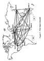
- nodes In a network, nodes must be able to exchange information with other nodes of a same group. For instance, the broadcast of a same information to multiple nodes located in different locations is called "Multicast". In a group of N nodes called a Multicast group as illustrated in Figure 1 , each node (101) needs to communicate with the (N-1) other nodes. To do this, each node establishes a session with each other node (100).
- TCP Transmission Control Protocol
- UDP User Datagram Protocol
- Nx(N-1)/2 TCP sessions are required. It is important to note that since a TCP session is bidirectional, the required number of sessions is Nx(N-1)/2 and not Nx(N-1).
- the number of sessions can be considerable in a network comprising hundreds or thousands of nodes. It can results an important overhead with a significant impact in term of bandwidth consumption in the network and resource (data processing and memory) utilisation in each node.
- the establishment the TCP sessions requires data processing resources and the maintenance of these TCP sessions requires memory in particular to store the context of the TCP sessions (TCP Control Block).
- the nodes can exchange the same piece of information on all the TCP sessions at the same time (communication any to any). This is bandwidth consuming at the network level and resource consuming at the level of each node.
- An example of this scenario is the exchange of routing information between routers. Each router broadcast routing information to the other routers either periodically or when a change occurs, depending on the routing protocol used in the network.
- Another example is the synchronisation of multiple servers in a distributed database.
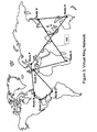
- a solution illustrated in Figure 2 is to select a "Rendezvous Point", or a central node, to which all other nodes are connected.
- the central node (200) is responsible for distributing the information to all the other nodes in the network.
- This configuration called “Star network” reduces the number of connections (N-1 sessions) but the main drawback is due to the fact that the central node is the weakest point of the network.
- the central node is duplicated by means of a backup central node (201).
- This configuration called “Dual star network” requires (N - 1) + (N -2) connections.
- the central node (200) is connected to all other nodes including the backup central node (201). The result is the establishment of N-1 TCP sessions.
- the addition of a second star configuration based on the backup central node (201) requires another N-1 TCP sessions. However, since a TCP session already exists between central node (200) and backup central node (201), this session does not need to be duplicated.
- EP A 0561381 discloses a data communications network in which multiple host processors are linked in a ring network by respective network interface processors or nodes includes circuitry in each of the nodes which aids in the implementation of a distributed resource locking scheme and a reliable multicasting system.
- the present invention is directed to a method, node and computer program as defined in independent claims, within a network comprising a transport layer protocol providing end to end data transfer, for multicasting datagrams on a virtual ring, each node on the virtual ring being logically connected according to the network transport layer protocol to two and only two neighbor nodes through virtual connections, an upstream neighbor node and a downstream neighbor node.
- the present invention discloses a network topology based on a virtual ring.
- the N nodes of the network that need to communicate together are logically/virtually connected according to a virtual ring, each node communicating with two and only two neighbor nodes: an upstream neighbor node and a downstream neighbor node.
- this invention applies to any types of nodes, this invention is particularly interesting when several nodes need to exchange a same piece of information between them.
- Each virtual ring can be implemented on a same physical network, each virtual ring allowing a subset of nodes to communicate together.
- a same node can participate to several virtual rings at the same time.
- Each virtual ring is identified by a unique identifier (named Virtual Ring Id).
- the Virtual Ring identifier is statically configured in all the nodes participating in the virtual ring. The way the virtual ring is initiated and managed will be described hereafter.
- the current invention is implemented on top of the TCP layer of the TCP/IP protocol, which is today the protocol the most largely used in the world.
- the invention only uses the transport function of TCP.
- IPX Internetwork Packet Exchange
- IP Internet Protocol
- TCP Transmission Control Protocol
- TCP has been chosen because it allows a sending of packets without risk of loss.
- TCP also informs of the loss of the remote node by maintaining a connection.
- IP and IP allows to extend the virtual ring to any part of an IP network including the Internet itself. It is possible to imagine nodes in different parts of the world, communicating together with such a virtual ring.
- the User Datagram Protocol can also be used in the current invention for instance to exchange Ring Insertion and Ring Removal messages between a specific node and the Virtual Ring Manager. Since these messages are exchanged only during the insertion or removal process, there is no need to use the TCP protocol and to establish a TCP session.
- the present invention requires a new specific piece of code in each node part of the ring network.
- This code uses a specific TCP port and a specific UDP port reserved for the invention. This code is used to establish, maintain and tear down the virtual ring topology
- token referring to the "Token Ring” architecture developed by IBM (IBM is a trademark of International Business Machines Corporation) these last decades.
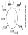
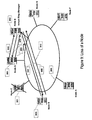
- Figure 4 describes a token (401) circulating between node A and node B on a virtual ring (400).
- the token is used as a periodic keepalive message to validate the ring topology.
- the token is periodically generated by the Virtual Ring Manager (402) and forwarded by each node to its downstream neighbor node.
- the receipt by the Virtual Ring Manager of the token indicates that the ring topology is valid and the loop is not broken. If the ring is broken for some reason (loss of one node, loss of connectivity between 2 neighbor nodes), the loss of the token will indicate that there is a problem on the ring.
- Each node monitors the reception of the token. If the token has not been received after a certain amount of time, each node will trigger the Ring Recovery process detailed here after.
- the token is forwarded from node to node, just like any other piece of information. This means that the Token uses the TCP sessions established between the nodes.
- the Sequence Number field is used to identify the current copy of the token.
- IP Header (20 bytes) TCP Header Source/Dest Port (20 bytes) Virtual Ring Header Message Code 0x0000 Virtual Ring Identifier (2 bytes) Sender IP address (4 bytes)
- Datagrams exchanged on the virtual ring have the following encapsulation: IP Header (20 bytes) TCP Header Source/Dest Port (20 bytes) Virtual Ring Header Message Code 0x0000 Virtual Ring Identifier (2 bytes) Sender IP address (4 bytes) Data
- the encapsulation of the Data inside a TCP datagram has the following advantage : the datagram is transmitted along the Virtual Ring using the reliable TCP protocol.
- the Virtual Ring Header comprises the following fields:
- the virtual ring is a list of nodes connected to form a ring. No node has the complete view of the ring. This list of nodes participating in the ring is stored nowhere in the network. Each node comprises the following information (Node Ring Record) : Virtual Ring Identifier (2 bytes) (configured) Usptream Neighbor IP address (4 bytes) Dowstream Neighbor IP address (4 bytes) Virtual Ring Manager IP address (configured) (4 bytes) Backup Virtual Ring Manager IP address (configured) (4 bytes)
- the Virtual Ring Manager is responsible for maintaining the topology of the virtual ring, more particularly the Virtual Ring Manager is responsible for the insertion and removal of the nodes.
- the Virtual Ring Manager IP address is statically configured in each node of the virtual ring. Since the Virtual Ring Manager constitutes a single point of failure, a Backup Virtual Ring Manager is generally used. The IP address of the Backup Virtual Ring Manager is also statically configured in each node. When a node wants to be inserted into the virtual ring and does not receive any response from the Virtual Ring Manager, this node will contact the Backup Virtual Ring Manager.
- Figure 6 describes the insertion of a new node G (601) into a virtual ring (600) comprising nodes A, B, C, D, E, F.
- Node G (701) is now inserted on the virtual ring (700), between the Virtual Ring Manager (702) and Node F (703).
- the solicited node removal scenario described in the present section correspond to the case where a node wants to be removed from the Virtual Ring because it does not want to participate any more in the group.
- Another node removal scenario corresponds to the case where a node has a failure and the virtual ring is broken. This unsolicited removal scenario will be described in another section.
- Figure 8 describes the Node Solicited removal process.
- the loss of a node in the virtual ring network is detected by its neighbor nodes with the loss the TCP connections.
- a node is removed from the virtual ring without informing the Virtual Ring Manager by means of a "Virtual Ring Removal Request" message (which should be the case when a node failure occurs)
- the 2 neighbor nodes (upstream and downstream) lose their TCP connection with this node a given period of time (after a TCP timeout).
- a TCP timeout As described in Figure 9 ; the following scenario occurs:
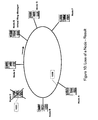
- Figure 10 shows the result of the virtual ring (1000) reconfiguration after the loss of Node C (1001).
- the Backup Virtual Ring Manager executes the same processes as the Virtual Ring Manager.
- the Backup Virtual Ring Manager receives Insertion, Removal and Recovery messages from the nodes in absence of response from the Virtual Ring Manager, and processes these messages like the Virtual Ring Manager.
- All the nodes including the Virtual Ring Manager use a timer to detect the loss of the token. When the token is lost, the ring needs to be rebuilt. The value of this timer must be larger than the TCP session timer to allow the process described in section entitled “Loss of a node” to take place before the reconfiguration of the ring.
- a node detects the loss of the token, it sends a "Virtual Ring Removal Request” message to the Virtual Ring Manager and waits for the confirmation as described in Figure 8 (refer to section entitled “Solicited Node Removal”). After a given period of time, the node will send a "Virtual Ring Insertion Request” message to the Virtual Ring Manager to participate again in the ring as described in Figure 6 (section entitled “Insertion of a Node”).
- UDP User Datagram Protocol
- the value of the Virtual Ring Identifier field is used to identify the current virtual ring.
- the Virtual Ring Identifier is statically configured in each participating node.
- Neighbor IP Message Code Virtual ring Upstream Downstream Node IP 0x0008 Identifier Neighbor IP Neighbor IP address (2 bytes) address address (4 bytes) (4 bytes) (4 bytes)
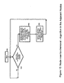
- Figure 11 describes the algorithm executed by a node when this node receives the Token.
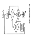
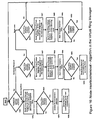
- Figure 12 describes the algorithm executed in the Virtual Ring Manager at receipt of the Token.
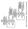
- Figure 13 describes the algorithm executed in a node in view of inserting this node into the virtual ring.
- Figure 14 describes the algorithm executed in a node in view of removing this node from the virtual ring.
- Figure 15 illustrates the algorithm executed in a node when a neighbor node has been inserted or removed.
- Figure 16 illustrates the algorithm executed in the Virtual Ring Manager when a node is inserted or removed from the virtual ring.
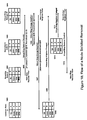
- FIG. 17 illustrates the Node Insertion process.
- FIG. 18 illustrates the Solicited Node Removal process.
- FIG. 19 illustrates the unsolicited Node Removal process.
- a session is a virtual connection between two nodes, enabling the exchange of data between these nodes and taking care of transmission problems like flow control and retransmission.
- a TCP session is an example of session between two nodes supporting the TCP/IP protocol.
- the current invention is implemented on top of the TCP (Transmission Control Protocol) layer of the TCP/IP protocol stack, and can be used by any node supported the TCP/IP protocol, which is the protocol the most widely used in the world.
- TCP Transmission Control Protocol
- each node has to establish a TCP session with each of the N-1 other nodes. This means the establishment of Nx(N-1)/2 TCP sessions.
- each node has to establish a TCP session with only 2 other nodes: the upstream neighbor node and the downstream neighbor node. This means a total of N sessions in a virtual ring of N nodes.
- the saving resulting from the present invention can be calculated as follows:
- each node receives one and only one copy of a same message, the present invention avoids multiple and unnecessary copies.
- each node communicates with all the other nodes. If each node needs to send the same piece of information to the other nodes, each node will forward this piece of information to all its neighbor nodes, and this will duplicate the number of messages exchanged in the network. This is typically the case when the nodes are routers exchanging routing information using a routing protocol like RIP (routing Information Protocol). Periodically, each router communicates, or floods, its routing table to the other routers in the network. Another example is when a distributed database needs to be synchronised, and when the servers participating in the distributed database need to exchange a same record.
- RIP routing Information Protocol
- the broadcast of information is managed by the application layer, which must take care of the way the information is distributed between the nodes.
- the present invention enable the exchange of a same piece of information between all the nodes so that each node receives one and only one copy of the information. Because nodes are virtually connected to a virtual ring, and because the information circulates along that ring and is seen by each node connected to the ring, the network is not flooded by multiple copies of messages exchanged between nodes.
- Establishing and Maintaining a TCP session requires computer resources to manage the flow control, the retransmission, and to generate acknowledgements and keepalives.
- the present invention reduces the number of TCP sessions required for nodes to communicate, and therefore reduces the utilization of data processing resources in nodes.
- the maintenance of TCP sessions requires to keep the context of these session, with information such as the sequence number of the last segment sent, or the sequence number of the next acknowledgement to send.
- the storage of this information consumes memory. Reducing the number of TCP sessions has for result to reduce the memory consumption in the nodes.
Abstract
Description
- The present invention relates to communication on digital networks, and more particularly to a system and a method for creating a virtual ring between nodes in a an Internet Protocol (IP) network and for multicasting datagrams to nodes part of this virtual ring.
- In the present description, the term "network" designates an ordinary network, based on the Internet Protocol (IP) technology. This network can be a Local Area Network (LAN), but also an Enterprise (private) Intranet or even the (public) internet. The term "Node" designates the computer systems in the network routing the communications, such as routers, and, also, the computer systems exchanging information on the network, such as workstations and servers.
- In a network, nodes must be able to exchange information with other nodes of a same group. For instance, the broadcast of a same information to multiple nodes located in different locations is called "Multicast". In a group of N nodes called a Multicast group as illustrated in
Figure 1 , each node (101) needs to communicate with the (N-1) other nodes. To do this, each node establishes a session with each other node (100). Usually in IP networks, the Transmission Control Protocol (TCP is used to communicate between nodes because this protocol allows a reliable transport of data through sessions and takes care of the flow control. This is not the case with the transport protocol called UDP (User Datagram Protocol) which is based on the best effort and which does not provide any session mechanism. - If a node, within a group of N nodes, wants to communicate information to all the other nodes of its group, it requires N-1 TCP sessions. If all the nodes need to communicate together in a full mesh configuration, Nx(N-1)/2 TCP sessions are required. It is important to note that since a TCP session is bidirectional, the required number of sessions is Nx(N-1)/2 and not Nx(N-1).
- The number of sessions can be considerable in a network comprising hundreds or thousands of nodes. It can results an important overhead with a significant impact in term of bandwidth consumption in the network and resource (data processing and memory) utilisation in each node. In each node, the establishment the TCP sessions requires data processing resources and the maintenance of these TCP sessions requires memory in particular to store the context of the TCP sessions (TCP Control Block).
- In absence of synchronisation at the application level, the nodes can exchange the same piece of information on all the TCP sessions at the same time (communication any to any). This is bandwidth consuming at the network level and resource consuming at the level of each node. An example of this scenario is the exchange of routing information between routers. Each router broadcast routing information to the other routers either periodically or when a change occurs, depending on the routing protocol used in the network. Another example is the synchronisation of multiple servers in a distributed database.
- Several solutions exist to limit the number of sessions between nodes. A solution illustrated in
Figure 2 , is to select a "Rendezvous Point", or a central node, to which all other nodes are connected. The central node (200) is responsible for distributing the information to all the other nodes in the network. This configuration called "Star network" reduces the number of connections (N-1 sessions) but the main drawback is due to the fact that the central node is the weakest point of the network. Generally, the central node is duplicated by means of a backup central node (201). This configuration called "Dual star network", requires (N - 1) + (N -2) connections. - Note: the central node (200) is connected to all other nodes including the backup central node (201). The result is the establishment of N-1 TCP sessions. The addition of a second star configuration based on the backup central node (201) requires another N-1 TCP sessions. However, since a TCP session already exists between central node (200) and backup central node (201), this session does not need to be duplicated. In conclusion, the number of sessions required in a dual star configuration is (N-1) + (N-2) = 2xN-3.
-
EP A 0561381 discloses a data communications network in which multiple host processors are linked in a ring network by respective network interface processors or nodes includes circuitry in each of the nodes which aids in the implementation of a distributed resource locking scheme and a reliable multicasting system. - It is an object of the invention to provide an improved backup virtual ring manager in an IP network comprising inter-communicating nodes.
- It is another object of the invention to reduce the resource consumption of inter-communicating nodes.
- it is a further object of the invention to define several groups of inter-communicating nodes in an IP network.
- The present invention is directed to a method, node and computer program as defined in independent claims, within a network comprising a transport layer protocol providing end to end data transfer, for multicasting datagrams on a virtual ring, each node on the virtual ring being logically connected according to the network transport layer protocol to two and only two neighbor nodes through virtual connections, an upstream neighbor node and a downstream neighbor node.
- Further embodiments of the invention are provided in the appended dependent claims.
- The foregoing, together with other objects, features, and advantages of this invention can be better appreciated with reference to the following specification, claims and drawings.
- The new and inventive features believed characteristics of the invention are set forth
FR9-2002-0038 04804621.3 -
Figure 1 shows an example of "Full mesh network". -
Figure 2 shows an example of "Star network". -
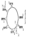
Figure 3 shows an example of "Virtual Ring network" according to the present invention. -
Figure 4 shows how a token is forwarded from node to node on a Virtual Ring according to the present invention. -
Figure 5 shows the token message according to the present invention. -
Figure 6 shows how a new node is inserted into the Virtual Ring according to the present invention. -
Figure 7 shows the result of a new node insertion according to the present invention. -
Figure 8 shows the solicited removal of a node according to the present invention. -
Figure 9 shows the loss of a node according to the present invention. -
Figure 10 shows the result of a reconfiguration after the loss of a node according to the present invention. -
Figure 11 describes the algorithm executed by a node when this node receives the token according to the present invention. -
Figure 12 describes the algorithm executed in the Virtual Ring Manager at receipt of the token according to the present invention. -
Figure 13 describes the algorithm executed in a node in view of inserting this node into the Virtual Ring according to the present invention. -
Figure 14 describes the algorithm executed in a node in view of removing this node from the Virtual Ring according to the present invention. -
Figure 15 illustrates the algorithm executed in a node when a neighbor node has been inserted or removed according to the present invention. -
Figure 16 illustrates the algorithm executed in the Virtual Ring Manager when a node is inserted or removed from the Virtual Ring according to the present invention. -
Figure 17 illustrates the Node Insertion process according to the present invention. -
Figure 18 illustrates the Solicited Node Removal process according to the present invention. -
Figure 19 illustrates the unsolicited Node Removal process according to the present invention. - The present invention discloses a network topology based on a virtual ring. The N nodes of the network that need to communicate together, are logically/virtually connected according to a virtual ring, each node communicating with two and only two neighbor nodes: an upstream neighbor node and a downstream neighbor node.
- Although the present invention applies to any types of nodes, this invention is particularly interesting when several nodes need to exchange a same piece of information between them.
- Several virtual rings can be implemented on a same physical network, each virtual ring allowing a subset of nodes to communicate together. A same node can participate to several virtual rings at the same time. Each virtual ring is identified by a unique identifier (named Virtual Ring Id). The Virtual Ring identifier is statically configured in all the nodes participating in the virtual ring. The way the virtual ring is initiated and managed will be described hereafter.
- In a preferred embodiment, the current invention is implemented on top of the TCP layer of the TCP/IP protocol, which is today the protocol the most largely used in the world. However, the invention only uses the transport function of TCP. It is also possible to implement the invention on top of any other protocol stack providing the transport function, such as IPX (Internetwork Packet Exchange). IP has been chosen in the present description because this protocol is used in most of the networks. The transport function of TCP brings some reliability because this function handles transmission problems such as packet losses. The circulation of information along the virtual ring is based on the Internet Protocol (IP) and the Transmission Control Protocol (TCP). TCP has been chosen because it allows a sending of packets without risk of loss. TCP also informs of the loss of the remote node by maintaining a connection. The use of TCP and IP allows to extend the virtual ring to any part of an IP network including the Internet itself. It is possible to imagine nodes in different parts of the world, communicating together with such a virtual ring.
- The User Datagram Protocol (UDP) can also be used in the current invention for instance to exchange Ring Insertion and Ring Removal messages between a specific node and the Virtual Ring Manager. Since these messages are exchanged only during the insertion or removal process, there is no need to use the TCP protocol and to establish a TCP session.
- The present invention requires a new specific piece of code in each node part of the ring network. This code uses a specific TCP port and a specific UDP port reserved for the invention. This code is used to establish, maintain and tear down the virtual ring topology
- In order to maintain the ring topology, some pieces of information need to be periodically exchanged between the different nodes. One of these pieces of information is called "token", referring to the "Token Ring" architecture developed by IBM (IBM is a trademark of International Business Machines Corporation) these last decades.
Figure 4 describes a token (401) circulating between node A and node B on a virtual ring (400). - The token is used as a periodic keepalive message to validate the ring topology. The token is periodically generated by the Virtual Ring Manager (402) and forwarded by each node to its downstream neighbor node. The receipt by the Virtual Ring Manager of the token (from its upstream neighbor node), indicates that the ring topology is valid and the loop is not broken. If the ring is broken for some reason (loss of one node, loss of connectivity between 2 neighbor nodes), the loss of the token will indicate that there is a problem on the ring. Each node monitors the reception of the token. If the token has not been received after a certain amount of time, each node will trigger the Ring Recovery process detailed here after. The token is forwarded from node to node, just like any other piece of information. This means that the Token uses the TCP sessions established between the nodes.
- The Sequence Number field is used to identify the current copy of the token.
-
IP Header IP header Virtual Ring Token
Message Code 0x0001
Virtual Ring Identifier (2bytes)
Sequence Number (4bytes) - The Token is described in
Figure 5 - IP header (500): source IP address of the sending node and destination IP address of the next node in the virtual ring
- TCP header (501): source and destination ports = well known port reserved for the current invention
- Virtual Ring Token (502): This message contains 3 fields:
- 1. Message code (503), set to 0x0001. Allows to identify that the type of message is a Token.
- 2. Virtual Ring Identifier (504) on 2 bytes: identify the Virtual Ring. This allows a same node to participate to multiple Virtual Rings.
- 3. Sequence Number (505) on 4 bytes: it is set and incremented by the Virtual Ring Manager. This allows the Virtual Ring Manager to detect a possible duplication of the token.
- When a node participating in the virtual ring receives a datagram from its upstream neighbor node, it processes this datagram, i.e stores the data part of the received message, and forwards it to its downstream neighbor node so that the datagram can circulate along the virtual ring. However, a node connected to the virtual ring must be able to recognize a datagram circulating along the virtual ring versus a normal IP datagram received from another node which does not participate in the virtual ring. To do so, datagrams exchanged on the virtual ring have the following encapsulation:
IP Header
(20 bytes)TCP Header
Source/Dest Port
(20 bytes)Virtual Ring Header
Message Code 0x0000
Virtual Ring Identifier (2 bytes)
Sender IP address (4 bytes)Data - The encapsulation of the Data inside a TCP datagram has the following advantage : the datagram is transmitted along the Virtual Ring using the reliable TCP protocol. The Virtual Ring Header comprises the following fields:
- 1. Message code : indicates that the received message is a datagram
- 2. Virtual Ring Identifier: indicates on which Virtual Ring the message must be forwarded. A node may belong to multiple Virtual Rings.
- 3. Sender IP address: This is the IP address of the node who has generated the data.
-
- 1/ When a node needs to send a datagram on the Virtual Ring, this node adds the Virtual Ring Header described above, and encapsulates the data inside a TCP datagram. This datagram is sent to the downstream neighbor on the Virtual Ring.
- 2/ Each node on the Virtual Ring checks the sender address to see which node has generated the datagram. Each node then reads the data, processes it, and forwards the datagram to its downstream neighbour.
- 3/ When the datagram is received back by the sender Node (the sender Node checks the Sender IP address in the Virtual Ring Header), then the Sender Node removes the datagram from the Virtual Ring. This just means that the datagram is deleted and not forwarded to the downstream neighbor node again.
- The virtual ring is a list of nodes connected to form a ring. No node has the complete view of the ring. This list of nodes participating in the ring is stored nowhere in the network. Each node comprises the following information (Node Ring Record) :
Virtual Ring Identifier (2 bytes) (configured) Usptream Neighbor IP address (4 bytes) Dowstream Neighbor IP address (4 bytes) Virtual Ring Manager IP address (configured) (4 bytes) Backup Virtual Ring Manager IP address (configured) (4 bytes) - One of the nodes participating in the virtual ring plays the role of "Virtual Ring Manager". The Virtual Ring Manager is responsible for maintaining the topology of the virtual ring, more particularly the Virtual Ring Manager is responsible for the insertion and removal of the nodes.
- It is important to note that the Virtual Ring Manager IP address is statically configured in each node of the virtual ring. Since the Virtual Ring Manager constitutes a single point of failure, a Backup Virtual Ring Manager is generally used. The IP address of the Backup Virtual Ring Manager is also statically configured in each node. When a node wants to be inserted into the virtual ring and does not receive any response from the Virtual Ring Manager, this node will contact the Backup Virtual Ring Manager.
-
Figure 6 describes the insertion of a new node G (601) into a virtual ring (600) comprising nodes A, B, C, D, E, F. When a new node G (601) wants to join the virtual ring (600), the following scenario occurs: - Note: in a preferred embodiment, all the insertion messages use the UDP protocol and the reserved UDP port defined in the current invention.
- The Node (601) to insert in the virtual ring (Node G), sends a "Virtual Ring Insertion Request" message (603) to the Virtual Ring Manager (602) using the configured IP address of the Virtual Ring Manager. The Node (601) to insert starts an "Insertion Request" timer and waits for a "Virtual Ring Insertion Confirmation" message (604).
- The Virtual Ring Manager (602) receives the "Virtual Ring Insertion Request" message and notes the source IP address of the message, which is the IP address of Node G (601).
- The Virtual Ring Manager (602) sends a "Virtual Ring Change Neighbor" message (605) to its downstream neighbor Node F (606). The Virtual Ring Manager finds the IP address of Node F in its Node Ring Record. The "Virtual Ring Change Neighbor" message comprises the IP address of Node G (601) as Upstream Neighbor IP address. The Downstream Neighbor IP address in the message is set to 0.0.0.0 because this address does not need to be changed.
- Node F (606) receives the "virtual Ring Change Neighbor" message (605). Node F tears the TCP session down with its upstream neighbor Node (the Virtual Ring Manager), by issuing a "TCP Reset" message. Node F (606) stores the IP address of Node G (601) received in the "Virtual Ring Change Neighbor" Message (605), in its Node Ring Record (Upstream Neighbor IP address).
- Node F (606) establishes a TCP session with its new upstream neighbor Node, (Node G (601)) and sends a "Virtual Ring Neighbor Changed" message (607) to the Virtual Ring Manager (602) to indicate that Node F has changed its upstream neighbor Node.
- The Virtual Ring Manager (602) receives the "TCP Reset" message from Node F (606) and tears the TCP session down. The Virtual Ring Manager establishes a new TCP session with Node G (601) and stores the IP address of Node G (601) in its Node Ring Record: Downstream Neighbor IP address.
- The Virtual Ring Manager (602) sends a "Virtual Ring Insertion Confirmation" message (604) to Node G (601). This message comprises the IP address of Node F (606).
- Node G (601) updates its Node Ring Record with :
- an Upstream Neighbor IP address equal to the Virtual Ring Manager IP address, and
- an Downstream Neighbor IP address equal to the IP address of Node F.
- If the "Insertion Request" timer expires, this means that Node G (601) has not received the "Virtual Ring Insertion Confirmation" message (604) from the Virtual Ring Manager (602). In that case, Node G (601) contacts the Backup Virtual Ring Manager (608). This process is described below in the section related to the Backup Virtual Ring Manager.
- The result of the insertion of node G is described in
Figure 7 . Node G (701) is now inserted on the virtual ring (700), between the Virtual Ring Manager (702) and Node F (703). - The solicited node removal scenario described in the present section correspond to the case where a node wants to be removed from the Virtual Ring because it does not want to participate any more in the group.
- Another node removal scenario corresponds to the case where a node has a failure and the virtual ring is broken. This unsolicited removal scenario will be described in another section.
-
Figure 8 describes the Node Solicited removal process. When Node C (801) wants to be removed from the virtual ring, the following scenario occurs: - Node C (801) sends a "Virtual Ring Removal Request" message (803) to the Virtual Ring Manager (802). This message comprises
- the IP address of Node C (801),
- the IP address of its upstream neighbor node, Node B (804), and
- the IP address of its downstream neighbor node, Node D (805).
- The Virtual Ring Manager (802) receives the "Virtual Ring Removal Request" message (803) from Node C (801) and starts the removal process. It notes the IP addresses of the upstream neighbor node and downstream neighbor node of Node C.
- The Virtual Ring Manager (802) sends a "Virtual Ring Change Neighbor" message (807) to Node B (804), upstream neighbor node of the node to remove, Node C (801). This message comprises:
- the unchanged Upstream Node IP address: 0.0.0.0;
- the Downstream Node IP address equal to the IP address of Node D (805), which is the downstream neighbor node of Node C (801)
- The Virtual Ring Manager (802) sends a "Virtual Ring Change Neighbor" message (808) to Node D (805), downstream neighbor node of the node to remove, Node C (801). This message comprises:
- the Upstream Node IP address equal to the IP address of Node B (804), which is the upstream neighbor node of Node C (801);
- the unchanged Downstream Node IP address: 0.0.0.0.
- Node B (804) receives the "Virtual Ring Change Neighbor" message (807) from the Virtual Ring Manager (802) and modifies its Node Ring Record.
The Upstream Node IP address in the message is 0.0.0.0. This means that the address does not need to be changed. Node B (804) keeps Node A (809) as its Upstream Neighbor node.
On the other hand, Node B (804) modifies its Downstream Neighbor IP address and uses the address received in the message. Node B (804) tears the TCP connection down with Node C (801) which was its previous downstream neighbor node, and establishes a new TCP connection with its new downstream neighbor node, Node D (805).
Node B (804) sends a "Virtual Ring Neighbor Changed" message (810) to the Virtual Ring Manager (802). - Node D (805) does the same as Node B (804). It updates its Node Ring Record, tears the TCP session it had with its Upstream Neighbor, Node C (801) down, and establishes a TCP session with its new Upstream Neighbor, Node B (804). Node D (805) sends a "Virtual Ring Neighbor Changed" message (811) to the Virtual Ring Manager (802)
- When the Virtual Ring Manager receives the "Virtual Ring Neighbor Changed" messages from both nodes B and C, it stops the "Change Neighbor" timer and sends a "Virtual Ring Removal Confirmation" message (806) to node C (801) to indicate that the Removal process has been successfull.
- Node C (801) stops the "Ring Removal" Timer. If the "Ring Removal" Timer expires, it means that the Virtual Ring Manager (802) has not achieved the Removal process. In this case, Node C (801) must contact the Backup Virtual Ring Manager (804).
- The loss of a node in the virtual ring network is detected by its neighbor nodes with the loss the TCP connections. When a node is removed from the virtual ring without informing the Virtual Ring Manager by means of a "Virtual Ring Removal Request" message (which should be the case when a node failure occurs), the 2 neighbor nodes (upstream and downstream) lose their TCP connection with this node a given period of time (after a TCP timeout). As described in
Figure 9 ; the following scenario occurs: - Node C (901) in the virtual ring network (900), fails or is powered off.
- Node B (903), the upstream neighbor node of Node C (901), loses its TCP connection with Node C. Node B attempts to re-establish its TCP connection without success.
- Node D (904), downstream neighbor node of Node C (901), loses its TCP connection with Node C. Node D attempts to re-establish its TCP connection without success.
- Node B (903) sends a "Virtual Ring Neighbor Loss Indication" (907) message to the Virtual Ring Manager (902). This message comprises:
- the Node B IP address, and
- the Node B Downstream Neighbor IP address, i.e. address of Node C (901).
- Node D (904) sends a "Virtual Ring Neighbor Loss Indication" (905) message to the Virtual Ring Manager (902). This message comprises:
- the Node D IP address, and
- the Node D Upstream Neighbor IP address, i.e. address of Node C (901).
- The Virtual Ring Manager (902) receives both messages from Node C upstream neighbor node and Node C downstream neighbor node. The virtual ring needs to be reconfigured.
- The Virtual Ring Manager (903) sends a "Virtual Ring Change Neighbor" message (906) to Node D (904). This message comprises:
- an Upstream Neighbor IP address equal to the Node B IP address
- an unchanged Downstream Neighbor IP address equal to 0.0.0.0 (the IP address does not need to be changed)
- Node D (904) updates the Upstream Neighbor IP address in its Node Ring Record and establishes a TCP connection with its new upstream neighbor node (Node B (903)).
- Node D (904) sends a "Virtual Ring Node Changed" (909) message back to the Virtual Ring Manager (902) to confirm the change.
- The Virtual Ring Manager (903) sends a "Virtual Ring Change Neighbor" message (908) to Node B (903) comprising:
- an unchanged Upstream Neighbor IP address equal to 0.0.0.0 (the IP address does not need to be changed)
- a Downstream Neighbor IP address equal to the Node D IP address.
- Node B (903) updates the Downstream Neighbor IP address in its Node Ring Record.
- Node B (903) sends a "virtual Ring Node Changed" message (910) back to the Virtual Ring Manager (902) to confirm the change.
-
Figure 10 shows the result of the virtual ring (1000) reconfiguration after the loss of Node C (1001). - The Backup Virtual Ring Manager executes the same processes as the Virtual Ring Manager. The Backup Virtual Ring Manager receives Insertion, Removal and Recovery messages from the nodes in absence of response from the Virtual Ring Manager, and processes these messages like the Virtual Ring Manager.
- All the nodes including the Virtual Ring Manager, use a timer to detect the loss of the token. When the token is lost, the ring needs to be rebuilt. The value of this timer must be larger than the TCP session timer to allow the process described in section entitled "Loss of a node" to take place before the reconfiguration of the ring. When a node detects the loss of the token, it sends a "Virtual Ring Removal Request" message to the Virtual Ring Manager and waits for the confirmation as described in
Figure 8 (refer to section entitled "Solicited Node Removal"). After a given period of time, the node will send a "Virtual Ring Insertion Request" message to the Virtual Ring Manager to participate again in the ring as described inFigure 6 (section entitled "Insertion of a Node"). - These messages are exchanged using the User Datagram Protocol (UDP). The value of the Virtual Ring Identifier field is used to identify the current virtual ring. The Virtual Ring Identifier is statically configured in each participating node.
-
IP Header TCP Header Virtual Ring Message Source/Dest Message Code 0x.. Port Virtual Ring Identifier (2 bytes) -
Message Code Virtual Ring Inserting Node IP address 0x0002 Identifier (2 bytes) (4 bytes) -
Message Code Virtual Ring Upstream Neighbor Downstream Neighbor 0x0003 Identifier (2 bytes) IP address (4 bytes) IP address (4 bytes) -
Message Code Virtual Ring Upstream Neighbor Downstream 0x0004 Identifier (2 bytes) IP address (4 bytes) Neighbor IP address (4 bytes) -
Message Code Virtual Ring Upstream Neighbor Downstream 0x0005 Identifier (2 bytes) IP address (4 bytes) Neighbor IP address (4 bytes) -
Message Code Virtual Ring Removing Upstream Downstream 0x0006 Identifier Node IP Neighbor IP Neighbor IP (2 bytes) address address address (4 bytes) (4 bytes) (4 bytes) -
Message Code Virtual Ring 0x0007 Identifier (2 bytes) -
Message Code Virtual ring Upstream Downstream Node IP 0x0008 Identifier Neighbor IP Neighbor IP address (2 bytes) address address (4 bytes) (4 bytes) (4 bytes) -
Figure 11 describes the algorithm executed by a node when this node receives the Token. - (1100) The Node has just been inserted into the virtual ring.
- (1101) The Node starts the Wait Token Timer (30 seconds) and waits for the receipt of the Token
- (1102) The Node checks whether the Token has been received or not.
- (1103) If no Token has been received, the Node checks whether the Token Timer has expired or not. If the Token Timer has not expired, the Node continues to wait for the Token.
- (1104) If the Token has been received, the Node checks the Token Sequence number to verify that it has been incremented since the last reception. If the Token is received for the first time (just after the node insertion), this test is not executed.
- (1105) If the Token Sequence number in the received Token is correct, the Node forwards the Token to its downstream neighbor node and waits for the Token again.
- (1106) If no Token has been received and if the Token Timer has expired, or if the received Token do not have the expected Token Sequence number (this means that a Token has been lost), then the Ring Recovery Procedure is executed.
-
Figure 12 describes the algorithm executed in the Virtual Ring Manager at receipt of the Token. - (1200) The Virtual Ring Manager has just been inserted. It sets the Token Sequence number to 1, starts a Wait Token Timer of 30 seconds and a Token Timer of 1 second. The Token Timer is used to generate a new Token every second. The Wait Token Timer is used to trigger the ring recovery.
- (1201) The Virtual Ring Manager forwards the Token to its downstream neighbor node and waits for the return of the Token.
- (1202) The Virtual Ring Manager checks whether the Token has been received or not.
- (1203) If the Token has not been received, the Virtual Ring Manager checks whether the Token Timer has expired or not.
- (1204) If the Token Timer has not expired, the Virtual Ring Manager checks whether the Wait Token Timer has expired or not. If not, the Virtual Ring Manager waits for the Token again.
- (1205) If no Token has been received and if the Wait Token Timer has expired, this means that the Token has been lost. Then the Virtual Ring Manager executes the ring recovery procedure.
- (1206) If the token is received, the Virtual Ring Manager checks the sequence number in the Token.
- (1207) The Virtual Ring Manager restarts the Wait Token Timer because the token has been received and wait for the Token timer to expire.
- (1208) When the Token Timer expires, the Virtual Ring Manager generates a new token, and increments the sequence number
- (1209) The Virtual Ring Manager forwards the Token to its downstream neighbor node and wait for the return of the Token.
-
Figure 13 describes the algorithm executed in a node in view of inserting this node into the virtual ring. - (1300) A new Node wants to be inserted into the Virtual Ring. This Node sends a "Virtual Ring Insertion Request" message to the Virtual Ring Manager.
- (1301) the Node starts the Insertion Timer and waits for an "Virtual Ring Insertion Confirmation" message from the Virtual Ring Manager.
- (1302) the Node checks whether an "Virtual Ring Insertion Confirmation" message has been received or not.
- (1303) If no "Virtual Ring Insertion Confirmation" message has been received, the Node checks if the insertion Timer has expired. If not, the Node continues to wait for the receipt of an "Virtual Ring Insertion Confirmation" message.
- (1304) If an "Virtual Ring Insertion Confirmation" message has been received, the Node stops the Insertion Timer, updates its neighbor addresses and establishes TCP sessions with its neighbor nodes.
- (1305) the new Node is now inserted into the virtual ring.
- (1306) If no "Virtual Ring Insertion confirmation" message has been received and if the Insertion Timer has expired, the Node sends an "Virtual Ring Insertion Request" message to the Backup Manager.
- (1307) the Node starts the Insertion Timer again.
- (1308) The Node checks whether an "Virtual Ring Insertion Confirmation" message has been received or not.
- (1309) If no "Virtual Ring Insertion Confirmation" message has been received, the Node checks whether the Insertion Timer has expired or not. If not, the Node continues to wait for the receipt of an "Insertion Confirmation" message.
- (1310) If an "Virtual Ring Insertion Confirmation" message has been received, the Node stops the Insertion Timer, updates its neighbor addresses and establishes TCP sessions with its neighbor nodes.
- (1311) the new Node is now inserted into the virtual ring.
- (1312) if no "Virtual Ring Insertion Confirmation" message has been received from the Backup Manager, this means that both the Virtual Ring Manager and the Backup Manager are unavailable. In this case, the process for inserting the Node in the ring has failed.
-
Figure 14 describes the algorithm executed in a node in view of removing this node from the virtual ring. - (1401) A Node wants to be removed from the virtual ring. This Node sends a "Virtual Ring Removal Request" message to the Virtual Ring Manager
- (1402) The Node to remove starts the Ring Removal Timer.
- (1403) The Node to remove waits for a "Virtual Ring Removal Confirmation" message from the Ring Manager.
- (1404) When the "Virtual Ring Removal Confirmation" message is received, the Node terminates its shutdown.
- (1405) If no "Virtual Ring Removal Confirmation" message is received, the Node to remove checks the Ring Removal Timer.
- (1406) If the Ring Removal Timer has expired, the Node to remove sends a "Virtual Ring Removal Request" message to the Backup Ring Manager
- (1407) The Node to remove starts the Ring Removal Timer.
- (1408) The Node to remove waits for the "Virtual Ring Removal Confirmation" message from the Ring Manager.
- (1409) If no "Virtual Ring Removal Confirmation" message is received, the Node to remove checks the Ring Removal Timer. If this timer expires, then the Node to remove terminates its shutdown without waiting for any response from the Ring Manager.
-
Figure 15 illustrates the algorithm executed in a node when a neighbor node has been inserted or removed. - (1501) The Adjacent Node checks if a "Virtual Ring Change Neighbor" message has been received from the Virtual Ring Manager.
- (1502) If a "Virtual Ring Change Neighbor" message has been received, the Adjacent Node updates its neighbor table using the upstream and downstream addresses received in the message.
- (1503) The Adjacent Node sends back a "Virtual Ring Neighbor Changed" message to the Virtual Ring Manager.
-
Figure 16 illustrates the algorithm executed in the Virtual Ring Manager when a node is inserted or removed from the virtual ring. - (1601) The Virtual Ring Manager checks if a "Virtual Ring Insertion Request" message has been received.
- (1602) If a "Virtual Ring Insertion Request" message has been received, the Virtual Ring Manager sends a "Virtual Ring Change Neighbor" message to its own downstream neighbor, and starts a Change Neighbor Timer.
- (1603) the Virtual Ring Manager waits for a "Virtual Ring Neighbor Changed" message. If no "Virtual Ring Neighbor Changed" message is received and the Change timer expires, then the procedure fails.
- (1604) the Virtual Ring Manager updates its downstream address with the • address of the new Node.
- (1605) The Virtual Ring Manager sends an "Virtual Ring Insertion Confirmation" message to the Node to insert.
- (1606) The Virtual Ring Manager checks if a "Virtual Ring Removal Request" message has been received.
- (1607) The Virtual Ring Manager sends a "Virtual Ring Change Neighbor" message to the downstream neighbor of the Node to remove.
- (1608) The Virtual Ring Manager sends a "Virtual Ring Change Neighbor" message to the upstream neighbor of the Node to remove.
- (1609) The Virtual Ring Manager starts the Change Neighbor Timer.
- (1610) When the "Virtual Ring Neighbor Changed" messages have been received from the upstream and the downstream neighbor nodes, the Virtual Ring Manager sends a "Virtual Ring Removal Confirmation" message to the Node to remove.
- (1611) The Virtual Ring Manager checks if a "Virtual Ring Neighbor Loss Indication" message has been received.
-
Figure 17 illustrates the Node Insertion process. - (1701) Node G is the Node to insert. Its ring table contains the Virtual Ring and Backup Ring Manager addresses.
- (1702) Node E is the Virtual Ring Manager.
- (1703) Node F is the downstream neighbor node of the Virtual Ring Manager.
- (1704) Inserting Node G sends a "Virtual Ring Insertion Request" message to the Virtual Ring Manager.
- (1705) The Virtual Ring Manager sends a "Virtual Ring Change Neighbor" message to its downstream neighbor node (node F) in order to insert the new Node G just before Node F.
- (1706) Node F updates its Virtual Ring table.
- (1707) Node F replies with a "Virtual Ring Neighbor Changed" message to the Virtual Ring Manager.
- (1708) The Virtual Ring Manager updates its Ring Table to insert the new Node G just after itself.
- (1709) The Virtual Ring Manager sends a "Virtual Ring Insertion Confirmation" message to the new inserting Node G.
- (1710) Node G updates its Virtual Ring table with the addresses of 2 adjacent nodes.
-
Figure 18 illustrates the Solicited Node Removal process. - (1801) Node B is the upstream neighbor node of Node C, the Node to remove.
- (1802) Node C is the Node to remove.
- (1803) Node D is the downstream neighbor node of Node C.
- (1804) Node E is the Virtual Ring Manager.
- (1805) Removing Node C sends a "Virtual Ring Removal Request" message to the Virtual Ring Manager.
- (1806) The Virtual Ring Manager sends a "Virtual Ring Change Neighbor" message to Node D (downstream neighbor node).
- (1807) The Virtual Ring Manager sends a "Virtual Ring Change Neighbor" to Node B (upstream neighbor node) and starts the Change Neighbor Timer.
- (1808) Node B updates its Ring Table.
- (1809) Node B sends a "Virtual Ring Neighbor Changed" message to the Virtual Ring Manager.
- (1810) Node D updates its Ring Table.
- (1811) Node D sends a "Virtual Ring Neighbor Changed" message to the Virtual Ring Manager.
- (1812) Virtual Ring Manager stops the Change Neighbor Timer and sends a "Virtual Ring Removal Confirmation" message to the Node C to remove.
-
Figure 19 illustrates the unsolicited Node Removal process. - (1901) Node B is the upstream neighbor node of Node C, the Node to remove.
- (1902) Node C is the Node to remove.
- (1903) Node D is the downstream neighbor node of Node C.
- (1904) Node E is the Virtual Ring Manager.
- (1905) The upstream neighbor node B detects the loss of the TCP connection with node C and sends a "Virtual Ring Loss Indication" message to the Virtual Ring Manager. • (1906) The downstream neighbor node D detects the loss of the TCP connection with node C and sends a "Virtual Ring Loss Indication" message to the Virtual Ring Manager.
- (1907) The Virtual Ring Manager sends a "Virtual Ring Change Neighbor" message to Node D (downstream neighbor node).
- (1908) The Virtual Ring Manager sends a "Virtual Ring Change Neighbor" message to Node B (upstream neighbor node) and starts the Change Neighbor Timer.
- (1909) Node B updates its Ring Table.
- (1910) Node B sends a "Virtual Ring Neighbor Changed" message to the Virtual Ring Manager.
- (1911) Node D updates its Ring Table.
- (1912) Node D sends a "Virtual Ring Neighbor Changed" message to the Virtual Ring Manager.
- With the present invention, only N TCP sessions are required to interconnect N nodes versus Nx(N-1)/2 sessions in a full meshed network or 2xN-3 sessions in a dual star configuration. A session is a virtual connection between two nodes, enabling the exchange of data between these nodes and taking care of transmission problems like flow control and retransmission. A TCP session is an example of session between two nodes supporting the TCP/IP protocol. The current invention is implemented on top of the TCP (Transmission Control Protocol) layer of the TCP/IP protocol stack, and can be used by any node supported the TCP/IP protocol, which is the protocol the most widely used in the world. As illustrated in
Figure 1 , in a full meshed network of N nodes, each node has to establish a TCP session with each of the N-1 other nodes. This means the establishment of Nx(N-1)/2 TCP sessions.
According to the present invention, each node has to establish a TCP session with only 2 other nodes: the upstream neighbor node and the downstream neighbor node.
This means a total of N sessions in a virtual ring of N nodes. The saving resulting from the present invention can be calculated as follows: - Nx(N-1)/2 sessions in a full meshed network versus N sessions in the virtual ring configuration. The difference is equal to Nx(N-1)/2-N = N2/2-N/2-N= N2/2-3N/2= Nx(N-3)/2. Therefore, the current invention allows to save Nx(N-3)/2 sessions in the network.
- Because each node receives one and only one copy of a same message, the present invention avoids multiple and unnecessary copies. In a full meshed topology as described in
Figure 1 , each node communicates with all the other nodes. If each node needs to send the same piece of information to the other nodes, each node will forward this piece of information to all its neighbor nodes, and this will duplicate the number of messages exchanged in the network. This is typically the case when the nodes are routers exchanging routing information using a routing protocol like RIP (routing Information Protocol). Periodically, each router communicates, or floods, its routing table to the other routers in the network. Another example is when a distributed database needs to be synchronised, and when the servers participating in the distributed database need to exchange a same record. Usually, the broadcast of information is managed by the application layer, which must take care of the way the information is distributed between the nodes.
The present invention enable the exchange of a same piece of information between all the nodes so that each node receives one and only one copy of the information. Because nodes are virtually connected to a virtual ring, and because the information circulates along that ring and is seen by each node connected to the ring, the network is not flooded by multiple copies of messages exchanged between nodes. - Establishing and Maintaining a TCP session requires computer resources to manage the flow control, the retransmission, and to generate acknowledgements and keepalives. The present invention reduces the number of TCP sessions required for nodes to communicate, and therefore reduces the utilization of data processing resources in nodes.
- In each node, the maintenance of TCP sessions requires to keep the context of these session, with information such as the sequence number of the last segment sent, or the sequence number of the next acknowledgement to send. The storage of this information consumes memory. Reducing the number of TCP sessions has for result to reduce the memory consumption in the nodes.
Claims (20)
- A method to use in a node within a network comprising a transport layer protocol providing end to end data transfer, for multicasting datagrams on a virtual ring, each node on the virtual ring being logically connected according to the network transport layer protocol to two and only two neighbor nodes through virtual connections, an upstream neighbor node and a downstream neighbor node, said method comprising the steps of:joining the virtual ring;wherein said joining the virtual ring comprises:- sending a virtual ring datagram to the downstream neighbor node on the virtual ring, said virtual ring datagram comprising: a virtual ring identifier; means for identifying the node originator of the virtual ring datagram; and data;- when a datagram is received, identifying the received datagram;- if the received datagram is a token: identifying the virtual ring; checking whether the token is valid or not; and if the token is valid, forwarding the token to the downstream neighbor node on the identified virtual ring;- if the received datagram is a virtual ring datagram: identifying the virtual ring; and checking the node originator of the received virtual ring datagram;- if the received virtual ring datagram has not been locally originated: processing data comprised in said virtual ring datagram; and forwarding said virtual ring datagram to the downstream neighbor node on the identified virtual ring;- if the received virtual ring datagram has been locally originated: removing the virtual ring datagram from the virtual ring;- sending to a virtual ring manager node previously defined on the virtual ring, an insertion request message comprising the address of the node and means for identifying the virtual ring, said step of sending an insertion request comprising starting an insertion timer;- when receiving an insertion confirmation message from the virtual ring manager node comprising the address of an upstream neighbor node and the address of a downstream neighbor node, stopping the insertion timer;and wherein, if the insertion timer expires, said joining the virtual ring further comprises:- sending an insertion request message, comprising the address of the node; and means for identifying the virtual ring, to a backup ring manager node previously defined on the virtual ring;- restarting the insertion timer;- when receiving an insertion confirmation message from the backup virtual ring manager node comprising the address of an upstream neighbor node and the address of a downstream neighbor node, stopping the insertion timer.
- The method according to claim 1 wherein:- the step of identifying the virtual ring when a token is received, comprises the further step of checking that the token has been sent by the upstream neighbor node on the identified virtual ring;- the step of identifying the virtual ring when a virtual datagram is received, comprises the further step of: checking that the virtual ring datagram has been sent by the upstream neighbor node on the identified virtual ring.
- The method according to any one of the preceding claims wherein:- a node on the virtual ring is defined as being a virtual ring manager node;- the token comprises a sequence number incremented each time the token is received by the virtual ring manager node;- the step of checking whether the token is valid or not, comprises the further step of checking whether or not the token sequence number has been incremented since the last reception.
- The method according to any one of the preceding claims wherein the step of checking whether or not the token is valid, comprises the further step of:- if the token is not valid, executing a recovery procedure.
- The method according to any one of the preceding claims wherein:- the step of forwarding the token to the downstream neighbor node on the identified virtual ring, comprises the further steps of: starting a timer and waiting for the return of the token; and executing a recovery procedure when the timer expires; the step of, receiving a token comprises the further step of stopping the timer.
- The method according to any one of the preceding claims wherein a node is a computer system routing datagrams in the network, preferably a router, or a computer system exchanging datagrams on the network, preferably a client or a server.
- The method, to use in a virtual ring manager node, according to any one of the preceding claims, comprising the preliminary steps of:- generating a token;- setting the token sequence number to an initial value;- forwarding said token to the downstream neighbor node on the virtual ring; and wherein:- the step of forwarding the token to the downstream neighbor node on the identified virtual ring, comprising the further step of incrementing the token sequence number;- the step of, executing a recovery procedure when the timer expires, comprising the further steps of: generating a new token; and forwarding said token to the downstream neighbor node on the virtual ring.
- The method according to any one of the preceding claims wherein the token is a datagram comprising:- a header comprising: a source address of the sending node; and a destination address of the next node on the virtual ring;- a header comprising: a source port; and a destination port;- means for identifying the datagram as being a token;- means for identifying the virtual ring;- a sequence number incremented each time the token is received by the virtual ring manager node.
- The method according to any one of the preceding claims wherein each virtual ring datagram circulating on the virtual ring comprises:- a header comprising: a source address of the sending node on the virtual ring, and a destination address of the next node on the virtual ring;- a header comprising: a source port; and a destination port;- a virtual ring header comprising: means for identifying the virtual ring datagram on the virtual ring; means for identifying the virtual ring; means for identifying the node originator of the virtual datagram; and data.
- The method according to any one of the preceding claims wherein comprising further the step of maintaining and updating the following information:- means for identifying the virtual ring;- the address of the upstream neighbor node;- the address of the downstream neighbor node;- the address of the virtual ring manager;- optionally, the address of a backup virtual ring manager.
- The method according to any one of the preceding claims comprising the further step of leaving the virtual ring, said step comprising the steps of:- sending to a virtual ring manager node previously defined on the virtual ring, a removal request message comprising: the address of the upstream neighbor node; the address of the downstream neighbor node; and the address of the node;- receiving a removal confirmation message from the virtual ring manager.
- The method according to claim 11, wherein the step of sending a removal request message, comprises the further step of: starting a removal timer; the step of receiving a removal confirmation message, comprises the further step of: stopping the removal timer; and wherein, if the removal timer expires, said method comprises the further steps of:- sending to a backup ring manager node previously defined on the virtual ring, a removal request message, comprising: the address of the upstream neighbor node; the address of the downstream neighbor node; and the address of the node;- restarting the removal timer;- receiving a removal confirmation message from the backup virtual ring manager;- stopping the removal timer.
- The method according to any one of the preceding claims comprising the further steps of :- receiving from a virtual ring manager node defined on the virtual ring, a change neighbor message comprising: the address of a new upstream neighbor node; or/and the address of a new downstream neighbor node;- maintaining: the address of the new upstream neighbor node; or/and the address of the new downstream neighbor node;- sending to the virtual ring manager node a neighbor changed confirmation message.
- The method, to use in a virtual ring manager node, according to any one of the preceding claims comprising the further steps of:- receiving an insertion request message comprising the IP address of a new node to insert into the virtual ring;- sending to the downstream neighbor node, a change neighbor message comprising the address of new node considered as the new upstream neighbor node of said downstream neighbor node;- receiving a neighbor changed confirmation message;- updating the address of the downstream neighbor node with the address of the new node;- sending to the new node an insertion confirmation message comprising: the address of the upstream neighbor node of the new node; the address of the downstream neighbor node of the new node.
- The method, to use in a virtual ring manager node, according to any one of the preceding claims comprising the further steps of:- receiving from a node on the virtual ring, a removal request message comprising: the address of the upstream node of the node to remove; the address of the downstream node of the node to remove; the address of the node to remove;- sending to the downstream neighbor node of the node to remove, a change neighbor message comprising: the address of the upstream neighbor node of the node to remove;- sending to the upstream neighbor node of the node to remove, a change neighbor message comprising: the address of the downstream neighbor node of the node to remove;- receiving a neighbor changed confirmation message from the upstream neighbor node and from the downstream neighbor node of the node to remove;- sending to the node to remove a removal confirmation message.
- The method, to use in a virtual ring manager node, according to any one of the preceding claims comprising the further steps of:- receiving a neighbor loss indication message indicating a loss of connection with an upstream neighbor node on the virtual ring; said neighbor loss indication message comprising: the address of the upstream neighbor node in failure; and the address of the node that has originated the neighbor loss indication message and detected the loss of connection with its upstream neighbor node;- sending to the downstream neighbor node of the node in failure a change neighbor message comprising: the address of a new upstream neighbor node;- receiving a neighbor changed message from the downstream neighbor node of the node in failure;- receiving a neighbor loss indication message indicating a loss of connection with a downstream neighbor node on the virtual ring; said neighbor loss indication message comprising: the address of the downstream neighbor node in failure; the address of the node that has originated the neighbor loss indication message and detected the loss of connection with its downstream neighbor node;- sending to the upstream neighbor node of the node in failure a change neighbor message comprising: the address of a new downstream neighbor node;- receiving a neighbor changed message from the upstream neighbor node of the node in failure.
- The method according to any one of the preceding claims wherein:- said network is a TCP/IP (Transmission Control Protocol/Internet Protocol) network;- logical connections between nodes part of the virtual ring are TCP sessions;- nodes are multicasting datagrams with their neighbor nodes, on the virtual ring, through said TCP sessions; and- addresses are IP addresses.
- The method according to any one of the preceding claims wherein messages exchanged between nodes for inserting a node or removing a node, are UDP (User Datagram Protocol) messages.
- A node being logically connectable according to a network transport layer protocol to two and only two neighbor nodes through virtual connections, an upstream neighbor node and a downstream neighbor node, comprising means adapted for carrying out the method according to any one of the preceding claims.
- A computer program comprising instructions for carrying out the method according to any one of claims 1 to 18 when said computer program is executed on a node.
Priority Applications (1)
| Application Number | Priority Date | Filing Date | Title |
|---|---|---|---|
| EP04804621A EP1695481B1 (en) | 2003-12-19 | 2004-11-30 | System and method for communicating on a virtual ring in an internet protocol network |
Applications Claiming Priority (3)
| Application Number | Priority Date | Filing Date | Title |
|---|---|---|---|
| EP03368121 | 2003-12-19 | ||
| PCT/EP2004/053185 WO2005060156A1 (en) | 2003-12-19 | 2004-11-30 | System and method for communicating on a virtual ring in an internet protocol network |
| EP04804621A EP1695481B1 (en) | 2003-12-19 | 2004-11-30 | System and method for communicating on a virtual ring in an internet protocol network |
Publications (2)
| Publication Number | Publication Date |
|---|---|
| EP1695481A1 EP1695481A1 (en) | 2006-08-30 |
| EP1695481B1 true EP1695481B1 (en) | 2011-01-12 |
Family
ID=34684636
Family Applications (1)
| Application Number | Title | Priority Date | Filing Date |
|---|---|---|---|
| EP04804621A Not-in-force EP1695481B1 (en) | 2003-12-19 | 2004-11-30 | System and method for communicating on a virtual ring in an internet protocol network |
Country Status (8)
| Country | Link |
|---|---|
| US (1) | US7733810B2 (en) |
| EP (1) | EP1695481B1 (en) |
| JP (1) | JP4678878B2 (en) |
| CN (1) | CN1894890B (en) |
| AT (1) | ATE495603T1 (en) |
| DE (1) | DE602004031048D1 (en) |
| TW (1) | TWI351852B (en) |
| WO (1) | WO2005060156A1 (en) |
Families Citing this family (25)
| Publication number | Priority date | Publication date | Assignee | Title |
|---|---|---|---|---|
| TWI351852B (en) * | 2003-12-19 | 2011-11-01 | Ibm | System and method for communicating on a virtual r |
| US7606199B2 (en) * | 2005-07-14 | 2009-10-20 | Sharp Laboratories Of America, Inc. | Central coordinator selection, handover, backup and failure recovery |
| US7715330B2 (en) | 2005-10-06 | 2010-05-11 | International Business Machines Corporation | System and method for optimizing the topology of a virtual ring based upon a TCP/IP network |
| US7483440B2 (en) | 2005-11-01 | 2009-01-27 | Ericsson Ab | Ring LSP topology for supporting VPNs over MPLS-based networks |
| US8570857B2 (en) * | 2006-04-07 | 2013-10-29 | At&T Intellectual Property I, Lp | Resilient IP ring protocol and architecture |
| EP1909436A1 (en) * | 2006-10-03 | 2008-04-09 | International Business Machines Corporation | System and method of integrating a node into a virtual ring |
| US8090256B2 (en) * | 2006-10-04 | 2012-01-03 | Arizona Board Of Regents, A Body Corporate Of The State Of Arizona, Acting For And On Behalf Of Arizona State University | Optical network architectures and optical communication schemes |
| US8295700B2 (en) * | 2007-05-14 | 2012-10-23 | Intune Technologies | Distributed packet switch for use in a network |
| US8345576B2 (en) * | 2007-06-19 | 2013-01-01 | Red Hat, Inc. | Methods and systems for dynamic subring definition within a multi-ring |
| KR101277368B1 (en) * | 2008-12-25 | 2013-06-20 | 미쓰비시덴키 가부시키가이샤 | Communication management device, communication node, communication system, and data communication method |
| KR101256767B1 (en) | 2008-12-25 | 2013-04-25 | 미쓰비시덴키 가부시키가이샤 | Communication management device, communication device, and communication method |
| CN102594592B (en) * | 2008-12-25 | 2015-03-25 | 三菱电机株式会社 | Communication management device, communication nodes, communication system and data communication method |
| GB0900667D0 (en) * | 2009-01-16 | 2009-02-25 | Univ Reading The | Processors |
| US8630837B2 (en) * | 2010-06-17 | 2014-01-14 | The Aerospace Corporation | Multicast emulation |
| JP5376066B2 (en) * | 2010-09-29 | 2013-12-25 | 富士通株式会社 | How to build a ring network |
| WO2012079651A1 (en) * | 2010-12-17 | 2012-06-21 | Telefonaktiebolaget L M Ericsson (Publ) | Ethernet ring node with improved recovery time after a link failure |
| US8509061B2 (en) * | 2011-03-23 | 2013-08-13 | Ciena Corporation | Systems and methods for scaling performance of Ethernet ring protection protocol |
| US9699021B2 (en) | 2011-11-21 | 2017-07-04 | Telefonaktiebolaget Lm Ericsson (Publ) | Ring protection state aware bandwidth adaptation |
| EP2792572B1 (en) * | 2011-12-12 | 2016-11-16 | Mitsubishi Electric Corporation | Train information management device and train information management method |
| US9559894B2 (en) * | 2012-08-22 | 2017-01-31 | Oracle International Corporation | System and method for supporting high available (HA) network communication in a middleware machine environment |
| US9350629B2 (en) | 2012-08-22 | 2016-05-24 | Oracle International Corporation | System and method for ensuring internet protocol (IP) address and node name consistency in a middleware machine environment |
| CN107276774B (en) * | 2016-04-08 | 2020-07-24 | 华为技术有限公司 | Multicast message transmission method and forwarding equipment |
| US10608840B2 (en) * | 2016-09-19 | 2020-03-31 | Simmonds Precision Products, Inc. | Automatic addressing of networked nodes |
| US11483209B2 (en) * | 2019-11-19 | 2022-10-25 | Advanced Micro Devices, Inc. | Forward progress mechanisms for a communications network having multiple nodes |
| US11463326B2 (en) * | 2021-02-24 | 2022-10-04 | Cisco Technology, Inc. | Lightweight ring manager with distributed policies |
Family Cites Families (43)
| Publication number | Priority date | Publication date | Assignee | Title |
|---|---|---|---|---|
| US4538147A (en) * | 1982-03-05 | 1985-08-27 | Burroughs Corp. | Bandwidth allocation in a token controlled loop communications network |
| US4590468A (en) * | 1983-03-10 | 1986-05-20 | Western Digital Corporation | Token access controller protocol and architecture |
| EP0192795B1 (en) * | 1985-02-28 | 1989-08-02 | International Business Machines Corporation | Communication system comprising overlayed multiple-access transmission networks |
| US5107490A (en) * | 1985-04-24 | 1992-04-21 | Artel Communications Corporation | Ring-type communication network |
| GB2175774B (en) * | 1985-05-24 | 1988-09-01 | Stc Plc | Intelligence transmission system of the local area network type |
| US4780871A (en) * | 1985-07-09 | 1988-10-25 | Canon Kabushiki Kaisha | Data Transmission system |
| US4736368A (en) * | 1985-12-16 | 1988-04-05 | Texas Instruments Incorporated | Priority token protocol circuit for a token ring local area network adaptor |
| JPS62284538A (en) * | 1986-06-03 | 1987-12-10 | Yaskawa Electric Mfg Co Ltd | Transmission system |
| US4766530A (en) * | 1986-11-24 | 1988-08-23 | Westinghouse Electric Corp. | Token passing scheme for a predetermined configuration local area network |
| US4860284A (en) * | 1988-04-20 | 1989-08-22 | American Telephone And Telegraph Company, At&T Bell Laboratories | Method and apparatus for identifying location of a lost token signal in a data communication network |
| JP2650961B2 (en) * | 1988-04-28 | 1997-09-10 | 株式会社日立製作所 | Control method for distributed control network |
| US5053946A (en) * | 1988-05-26 | 1991-10-01 | Digital Equipment Corporation | Token ring network having token request mechanism |
| US5253252A (en) * | 1989-01-10 | 1993-10-12 | The Foxboro Company | Token device for distributed time scheduling in a data processing system |
| US5243596A (en) * | 1992-03-18 | 1993-09-07 | Fischer & Porter Company | Network architecture suitable for multicasting and resource locking |
| US5289390A (en) * | 1992-05-22 | 1994-02-22 | Hewlett-Packard Company | Method for determining the electrical cable length of an active ring of a token ring local area network |
| US5383186A (en) * | 1993-05-04 | 1995-01-17 | The Regents Of The University Of Michigan | Apparatus and method for synchronous traffic bandwidth on a token ring network |
| GB2278258A (en) * | 1993-05-17 | 1994-11-23 | Ibm | Token ring network |
| US5490145A (en) * | 1993-05-25 | 1996-02-06 | Matsushita Electric Industrial Company, Ltd. | Communication system for a ring-type network |
| EP0719009B1 (en) * | 1994-12-23 | 1999-06-30 | Hewlett-Packard GmbH | Data communication network and method for the transmission of data packets in due time on a data communication network |
| US5710883A (en) * | 1995-03-10 | 1998-01-20 | Stanford University | Hypertext document transport mechanism for firewall-compatible distributed world-wide web publishing |
| US5886992A (en) * | 1995-04-14 | 1999-03-23 | Valtion Teknillinen Tutkimuskeskus | Frame synchronized ring system and method |
| US5604742A (en) * | 1995-05-31 | 1997-02-18 | International Business Machines Corporation | Communications system and method for efficient management of bandwidth in a FDDI station |
| US5802056A (en) * | 1995-07-12 | 1998-09-01 | Bay Networks, Inc. | Configuration of virtual rings in a token ring local area network |
| US5752003A (en) * | 1995-07-14 | 1998-05-12 | 3 Com Corporation | Architecture for managing traffic in a virtual LAN environment |
| EP0802655A3 (en) * | 1996-04-17 | 1999-11-24 | Matsushita Electric Industrial Co., Ltd. | Communication network |
| US6108713A (en) * | 1997-02-11 | 2000-08-22 | Xaqti Corporation | Media access control architectures and network management systems |
| US6154462A (en) * | 1997-08-21 | 2000-11-28 | Adc Telecommunications, Inc. | Circuits and methods for a ring network |
| TW419917B (en) * | 1998-03-30 | 2001-01-21 | Toshiba Corp | Communication network system |
| US6366556B1 (en) * | 1998-06-22 | 2002-04-02 | Lucent Technologies Inc. | Self-healing networks using virtual rings |
| US6563833B1 (en) * | 1999-01-05 | 2003-05-13 | Lucent Technologies Inc. | Combinatorial design method and apparatus for multi-ring networks with combined routing and flow control |
| US6460101B1 (en) * | 1999-11-09 | 2002-10-01 | International Business Machines Corporation | Token manager for execution of global operations utilizing multiple tokens |
| US6880017B1 (en) * | 2000-03-20 | 2005-04-12 | International Business Machines Corporation | System and method for providing an adaptive streaming flow control mechanism between the TCP and IP layers of the TCP/IP suite of protocols |
| JP2002009800A (en) * | 2000-06-19 | 2002-01-11 | Fujitsu Ltd | Broadcast method for ring type network system and its node device |
| US7047319B2 (en) * | 2001-02-15 | 2006-05-16 | International Business Machines Corporation | System and method for enabling a collision-free protocol over ethernet |
| US7106695B2 (en) * | 2001-05-29 | 2006-09-12 | International Business Machines Corporation | Method of allocating bandwidth to the stations of a local area network |
| US7181547B1 (en) * | 2001-06-28 | 2007-02-20 | Fortinet, Inc. | Identifying nodes in a ring network |
| US7130927B2 (en) * | 2001-07-05 | 2006-10-31 | International Business Machines Corporation | Method of bandwidth management between the stations of a local area network |
| US7248601B2 (en) * | 2001-08-09 | 2007-07-24 | International Business Machines Corporation | Method of allocating bandwidth on request to the stations of a local area network |
| US20030154285A1 (en) * | 2002-02-13 | 2003-08-14 | International Business Machines Corporation | Method and system for assigning network addreses |
| US7287170B2 (en) * | 2002-05-14 | 2007-10-23 | Ati Technologies Inc. | Method and apparatus for power management using system and request tokens |
| US7269731B2 (en) * | 2003-01-29 | 2007-09-11 | Hewlett-Packard Development Company, L.P. | Message authorization system and method |
| US7366109B2 (en) * | 2003-10-29 | 2008-04-29 | Nortel Networks Limited | Virtual private networks within a packet network having a mesh topology |
| TWI351852B (en) * | 2003-12-19 | 2011-11-01 | Ibm | System and method for communicating on a virtual r |
-
2004
- 2004-11-12 TW TW093134678A patent/TWI351852B/en not_active IP Right Cessation
- 2004-11-30 AT AT04804621T patent/ATE495603T1/en not_active IP Right Cessation
- 2004-11-30 WO PCT/EP2004/053185 patent/WO2005060156A1/en active Application Filing
- 2004-11-30 JP JP2006544412A patent/JP4678878B2/en not_active Expired - Fee Related
- 2004-11-30 US US10/596,641 patent/US7733810B2/en not_active Expired - Fee Related
- 2004-11-30 CN CN2004800374343A patent/CN1894890B/en not_active Expired - Fee Related
- 2004-11-30 EP EP04804621A patent/EP1695481B1/en not_active Not-in-force
- 2004-11-30 DE DE602004031048T patent/DE602004031048D1/en active Active
Also Published As
| Publication number | Publication date |
|---|---|
| US7733810B2 (en) | 2010-06-08 |
| CN1894890A (en) | 2007-01-10 |
| US20070268913A1 (en) | 2007-11-22 |
| JP2007515117A (en) | 2007-06-07 |
| EP1695481A1 (en) | 2006-08-30 |
| DE602004031048D1 (en) | 2011-02-24 |
| JP4678878B2 (en) | 2011-04-27 |
| TW200527856A (en) | 2005-08-16 |
| CN1894890B (en) | 2011-06-22 |
| ATE495603T1 (en) | 2011-01-15 |
| WO2005060156A1 (en) | 2005-06-30 |
| TWI351852B (en) | 2011-11-01 |
Similar Documents
| Publication | Publication Date | Title |
|---|---|---|
| EP1695481B1 (en) | System and method for communicating on a virtual ring in an internet protocol network | |
| US7065059B1 (en) | Technique for restoring adjacencies in OSPF in a non-stop forwarding intermediate node of a computer network | |
| EP1742430A1 (en) | Router redundancy in data communication networks | |
| US7715330B2 (en) | System and method for optimizing the topology of a virtual ring based upon a TCP/IP network | |
| CN105763359B (en) | Distributed bidirectional forwarding detection protocol (D-BFD) for an interleaved fabric switch cluster | |
| US6445710B1 (en) | Method and apparatus for transparently bridging traffic across wide area networks | |
| US7248579B1 (en) | System and method for providing a link state database (LSDB) snapshot for neighbor synchronization | |
| US7944811B2 (en) | Multiple multicast forwarder prevention during NSF recovery of control failures in a router | |
| US6298061B1 (en) | Port aggregation protocol | |
| US7801135B2 (en) | Transport protocol connection synchronization | |
| US7801857B2 (en) | Implicit routing in content based networks | |
| US6950427B1 (en) | Technique for resynchronizing LSDB in OSPF after a software reload in a non-stop forwarding intermediate node of a computer network | |
| US7787360B2 (en) | System and method for preserving multicast data forwarding during control failures in a router | |
| US8300646B2 (en) | Message handling in a local area network having redundant paths | |
| US20030123457A1 (en) | Apparatus and method for distributed software implementation of OSPF protocol | |
| JP2006101471A (en) | Multicast redundant path router, multicast redundant method | |
| US8442046B2 (en) | Sending routing protocol data on a multi-access network segment | |
| JP2007515117A5 (en) | ||
| US7324439B2 (en) | Application-transparent IP redundancy | |
| US10439929B2 (en) | Graceful recovery of a multicast-enabled switch | |
| US7639680B1 (en) | Out of band data base synchronization for OSPF | |
| EP1774683B1 (en) | System and method for preserving multicast data forwarding during control failures in a router | |
| WO1999048246A1 (en) | Method, apparatus, and medium for minimal time multicast graft/join restoration | |
| Ballardie et al. | Core Based Tree (CBT) Multicast | |
| JP2000049779A (en) | Multicast information distribution method by end node on digital communication network |
Legal Events
| Date | Code | Title | Description |
|---|---|---|---|
| PUAI | Public reference made under article 153(3) epc to a published international application that has entered the european phase |
Free format text: ORIGINAL CODE: 0009012 |
|
| 17P | Request for examination filed |
Effective date: 20060323 |
|
| AK | Designated contracting states |
Kind code of ref document: A1 Designated state(s): AT BE BG CH CY CZ DE DK EE ES FI FR GB GR HU IE IS IT LI LU MC NL PL PT RO SE SI SK TR |
|
| DAX | Request for extension of the european patent (deleted) | ||
| 17Q | First examination report despatched |
Effective date: 20070716 |
|
| RAP1 | Party data changed (applicant data changed or rights of an application transferred) |
Owner name: INTERNATIONAL BUSINESS MACHINES CORPORATION |
|
| GRAP | Despatch of communication of intention to grant a patent |
Free format text: ORIGINAL CODE: EPIDOSNIGR1 |
|
| GRAS | Grant fee paid |
Free format text: ORIGINAL CODE: EPIDOSNIGR3 |
|
| GRAA | (expected) grant |
Free format text: ORIGINAL CODE: 0009210 |
|
| AK | Designated contracting states |
Kind code of ref document: B1 Designated state(s): AT BE BG CH CY CZ DE DK EE ES FI FR GB GR HU IE IS IT LI LU MC NL PL PT RO SE SI SK TR |
|
| REG | Reference to a national code |
Ref country code: GB Ref legal event code: FG4D |
|
| REG | Reference to a national code |
Ref country code: CH Ref legal event code: EP |
|
| REG | Reference to a national code |
Ref country code: DE Ref legal event code: R084 Ref document number: 602004031048 Country of ref document: DE |
|
| REG | Reference to a national code |
Ref country code: IE Ref legal event code: FG4D |
|
| REF | Corresponds to: |
Ref document number: 602004031048 Country of ref document: DE Date of ref document: 20110224 Kind code of ref document: P |
|
| REG | Reference to a national code |
Ref country code: DE Ref legal event code: R096 Ref document number: 602004031048 Country of ref document: DE Effective date: 20110224 |
|
| REG | Reference to a national code |
Ref country code: GB Ref legal event code: 746 Effective date: 20110221 |
|
| REG | Reference to a national code |
Ref country code: NL Ref legal event code: VDEP Effective date: 20110112 |
|
| PG25 | Lapsed in a contracting state [announced via postgrant information from national office to epo] |
Ref country code: ES Free format text: LAPSE BECAUSE OF FAILURE TO SUBMIT A TRANSLATION OF THE DESCRIPTION OR TO PAY THE FEE WITHIN THE PRESCRIBED TIME-LIMIT Effective date: 20110423 Ref country code: SE Free format text: LAPSE BECAUSE OF FAILURE TO SUBMIT A TRANSLATION OF THE DESCRIPTION OR TO PAY THE FEE WITHIN THE PRESCRIBED TIME-LIMIT Effective date: 20110112 Ref country code: IS Free format text: LAPSE BECAUSE OF FAILURE TO SUBMIT A TRANSLATION OF THE DESCRIPTION OR TO PAY THE FEE WITHIN THE PRESCRIBED TIME-LIMIT Effective date: 20110512 Ref country code: GR Free format text: LAPSE BECAUSE OF FAILURE TO SUBMIT A TRANSLATION OF THE DESCRIPTION OR TO PAY THE FEE WITHIN THE PRESCRIBED TIME-LIMIT Effective date: 20110413 Ref country code: PT Free format text: LAPSE BECAUSE OF FAILURE TO SUBMIT A TRANSLATION OF THE DESCRIPTION OR TO PAY THE FEE WITHIN THE PRESCRIBED TIME-LIMIT Effective date: 20110512 |
|
| PG25 | Lapsed in a contracting state [announced via postgrant information from national office to epo] |
Ref country code: NL Free format text: LAPSE BECAUSE OF FAILURE TO SUBMIT A TRANSLATION OF THE DESCRIPTION OR TO PAY THE FEE WITHIN THE PRESCRIBED TIME-LIMIT Effective date: 20110112 Ref country code: CY Free format text: LAPSE BECAUSE OF FAILURE TO SUBMIT A TRANSLATION OF THE DESCRIPTION OR TO PAY THE FEE WITHIN THE PRESCRIBED TIME-LIMIT Effective date: 20110112 Ref country code: AT Free format text: LAPSE BECAUSE OF FAILURE TO SUBMIT A TRANSLATION OF THE DESCRIPTION OR TO PAY THE FEE WITHIN THE PRESCRIBED TIME-LIMIT Effective date: 20110112 Ref country code: PL Free format text: LAPSE BECAUSE OF FAILURE TO SUBMIT A TRANSLATION OF THE DESCRIPTION OR TO PAY THE FEE WITHIN THE PRESCRIBED TIME-LIMIT Effective date: 20110112 Ref country code: BG Free format text: LAPSE BECAUSE OF FAILURE TO SUBMIT A TRANSLATION OF THE DESCRIPTION OR TO PAY THE FEE WITHIN THE PRESCRIBED TIME-LIMIT Effective date: 20110412 Ref country code: BE Free format text: LAPSE BECAUSE OF FAILURE TO SUBMIT A TRANSLATION OF THE DESCRIPTION OR TO PAY THE FEE WITHIN THE PRESCRIBED TIME-LIMIT Effective date: 20110112 Ref country code: FI Free format text: LAPSE BECAUSE OF FAILURE TO SUBMIT A TRANSLATION OF THE DESCRIPTION OR TO PAY THE FEE WITHIN THE PRESCRIBED TIME-LIMIT Effective date: 20110112 Ref country code: SI Free format text: LAPSE BECAUSE OF FAILURE TO SUBMIT A TRANSLATION OF THE DESCRIPTION OR TO PAY THE FEE WITHIN THE PRESCRIBED TIME-LIMIT Effective date: 20110112 |
|
| PG25 | Lapsed in a contracting state [announced via postgrant information from national office to epo] |
Ref country code: DK Free format text: LAPSE BECAUSE OF FAILURE TO SUBMIT A TRANSLATION OF THE DESCRIPTION OR TO PAY THE FEE WITHIN THE PRESCRIBED TIME-LIMIT Effective date: 20110112 Ref country code: EE Free format text: LAPSE BECAUSE OF FAILURE TO SUBMIT A TRANSLATION OF THE DESCRIPTION OR TO PAY THE FEE WITHIN THE PRESCRIBED TIME-LIMIT Effective date: 20110112 |
|
| PLBE | No opposition filed within time limit |
Free format text: ORIGINAL CODE: 0009261 |
|
| STAA | Information on the status of an ep patent application or granted ep patent |
Free format text: STATUS: NO OPPOSITION FILED WITHIN TIME LIMIT |
|
| PG25 | Lapsed in a contracting state [announced via postgrant information from national office to epo] |
Ref country code: SK Free format text: LAPSE BECAUSE OF FAILURE TO SUBMIT A TRANSLATION OF THE DESCRIPTION OR TO PAY THE FEE WITHIN THE PRESCRIBED TIME-LIMIT Effective date: 20110112 Ref country code: CZ Free format text: LAPSE BECAUSE OF FAILURE TO SUBMIT A TRANSLATION OF THE DESCRIPTION OR TO PAY THE FEE WITHIN THE PRESCRIBED TIME-LIMIT Effective date: 20110112 Ref country code: RO Free format text: LAPSE BECAUSE OF FAILURE TO SUBMIT A TRANSLATION OF THE DESCRIPTION OR TO PAY THE FEE WITHIN THE PRESCRIBED TIME-LIMIT Effective date: 20110112 |
|
| 26N | No opposition filed |
Effective date: 20111013 |
|
| PG25 | Lapsed in a contracting state [announced via postgrant information from national office to epo] |
Ref country code: IT Free format text: LAPSE BECAUSE OF FAILURE TO SUBMIT A TRANSLATION OF THE DESCRIPTION OR TO PAY THE FEE WITHIN THE PRESCRIBED TIME-LIMIT Effective date: 20110112 |
|
| REG | Reference to a national code |
Ref country code: DE Ref legal event code: R097 Ref document number: 602004031048 Country of ref document: DE Effective date: 20111013 |
|
| PG25 | Lapsed in a contracting state [announced via postgrant information from national office to epo] |
Ref country code: MC Free format text: LAPSE BECAUSE OF NON-PAYMENT OF DUE FEES Effective date: 20111130 |
|
| REG | Reference to a national code |
Ref country code: CH Ref legal event code: PL |
|
| PG25 | Lapsed in a contracting state [announced via postgrant information from national office to epo] |
Ref country code: CH Free format text: LAPSE BECAUSE OF NON-PAYMENT OF DUE FEES Effective date: 20111130 Ref country code: LI Free format text: LAPSE BECAUSE OF NON-PAYMENT OF DUE FEES Effective date: 20111130 |
|
| REG | Reference to a national code |
Ref country code: IE Ref legal event code: MM4A |
|
| PG25 | Lapsed in a contracting state [announced via postgrant information from national office to epo] |
Ref country code: IE Free format text: LAPSE BECAUSE OF NON-PAYMENT OF DUE FEES Effective date: 20111130 |
|
| PGFP | Annual fee paid to national office [announced via postgrant information from national office to epo] |
Ref country code: FR Payment date: 20121206 Year of fee payment: 9 |
|
| PG25 | Lapsed in a contracting state [announced via postgrant information from national office to epo] |
Ref country code: LU Free format text: LAPSE BECAUSE OF NON-PAYMENT OF DUE FEES Effective date: 20111130 |
|
| PG25 | Lapsed in a contracting state [announced via postgrant information from national office to epo] |
Ref country code: TR Free format text: LAPSE BECAUSE OF FAILURE TO SUBMIT A TRANSLATION OF THE DESCRIPTION OR TO PAY THE FEE WITHIN THE PRESCRIBED TIME-LIMIT Effective date: 20110112 |
|
| PG25 | Lapsed in a contracting state [announced via postgrant information from national office to epo] |
Ref country code: HU Free format text: LAPSE BECAUSE OF FAILURE TO SUBMIT A TRANSLATION OF THE DESCRIPTION OR TO PAY THE FEE WITHIN THE PRESCRIBED TIME-LIMIT Effective date: 20110112 |
|
| REG | Reference to a national code |
Ref country code: FR Ref legal event code: ST Effective date: 20140731 |
|
| PG25 | Lapsed in a contracting state [announced via postgrant information from national office to epo] |
Ref country code: FR Free format text: LAPSE BECAUSE OF NON-PAYMENT OF DUE FEES Effective date: 20131202 |
|
| PGFP | Annual fee paid to national office [announced via postgrant information from national office to epo] |
Ref country code: DE Payment date: 20181031 Year of fee payment: 15 |
|
| PGFP | Annual fee paid to national office [announced via postgrant information from national office to epo] |
Ref country code: GB Payment date: 20181203 Year of fee payment: 15 |
|
| REG | Reference to a national code |
Ref country code: DE Ref legal event code: R119 Ref document number: 602004031048 Country of ref document: DE |
|
| GBPC | Gb: european patent ceased through non-payment of renewal fee |
Effective date: 20191130 |
|
| PG25 | Lapsed in a contracting state [announced via postgrant information from national office to epo] |
Ref country code: DE Free format text: LAPSE BECAUSE OF NON-PAYMENT OF DUE FEES Effective date: 20200603 Ref country code: GB Free format text: LAPSE BECAUSE OF NON-PAYMENT OF DUE FEES Effective date: 20191130 |