EP1688763A1 - Decision machine of detection tag using magnetic field - Google Patents
Decision machine of detection tag using magnetic field Download PDFInfo
- Publication number
- EP1688763A1 EP1688763A1 EP06100934A EP06100934A EP1688763A1 EP 1688763 A1 EP1688763 A1 EP 1688763A1 EP 06100934 A EP06100934 A EP 06100934A EP 06100934 A EP06100934 A EP 06100934A EP 1688763 A1 EP1688763 A1 EP 1688763A1
- Authority
- EP
- European Patent Office
- Prior art keywords
- detection
- coil
- magnetic field
- detection tag
- individual coils
- Prior art date
- Legal status (The legal status is an assumption and is not a legal conclusion. Google has not performed a legal analysis and makes no representation as to the accuracy of the status listed.)
- Withdrawn
Links
Images


Classifications
-
- G—PHYSICS
- G08—SIGNALLING
- G08B—SIGNALLING OR CALLING SYSTEMS; ORDER TELEGRAPHS; ALARM SYSTEMS
- G08B13/00—Burglar, theft or intruder alarms
- G08B13/22—Electrical actuation
- G08B13/24—Electrical actuation by interference with electromagnetic field distribution
- G08B13/2402—Electronic Article Surveillance [EAS], i.e. systems using tags for detecting removal of a tagged item from a secure area, e.g. tags for detecting shoplifting
- G08B13/2405—Electronic Article Surveillance [EAS], i.e. systems using tags for detecting removal of a tagged item from a secure area, e.g. tags for detecting shoplifting characterised by the tag technology used
- G08B13/2408—Electronic Article Surveillance [EAS], i.e. systems using tags for detecting removal of a tagged item from a secure area, e.g. tags for detecting shoplifting characterised by the tag technology used using ferromagnetic tags
- G08B13/2411—Tag deactivation
-
- G—PHYSICS
- G01—MEASURING; TESTING
- G01V—GEOPHYSICS; GRAVITATIONAL MEASUREMENTS; DETECTING MASSES OR OBJECTS; TAGS
- G01V15/00—Tags attached to, or associated with, an object, in order to enable detection of the object
Definitions
- the present invention relates to a decision machine of detection tag using magnetic field, used for confirmation of the deactivation of a magnetic detection tag (hereinafter referred to also as detection tag or EM tag). More particularly, the present invention relates to a decision machine of detection tag using magnetic field, which is used for confirming, after the deactivation operation of a detection tag, whether or not the detection tag has been deactivated reliably by a deactivation operation.
- Detection tags using a magnetic field as a detection means are known. They are attached to goods, etc., are carried with the goods and, when passing through particular gates, are detected by the gates; thereby, the circulation of goods is controlled and the theft of goods is prevented (Claim 1 of JP 1994-342065A). Such a detection tag using a magnetic field is also called EM (electric magnetic) tag.
- Fig. 12 shows a conventional detection tag.
- 160 is a soft magnetic substance layer containing cobalt, etc.
- On one side of the soft magnetic substance layer 160 is laminated, via a polyester-based adhesive layer 162, a hard magnetic substance layer 165 having a large number of through-holes 163 formed therein.
- the hard magnetic substance layer 165 contains a hard magnetic substance element(s) such as nickel or (and) the like.
- On the upper side of the hard magnetic substance layer 165 is laminated a protective layer 167 made of wood-free paper or a resin film.
- a release liner 169 On the other side of the soft magnetic substance layer 160 is laminated a release liner 169 via a pressure-sensitive adhesive layer 168.
- the release liner 169 is peeled and the release liner 169-removed detection tag is adhered to goods or the like to be controlled.
- Fig. 13 shows gates 170 and 172 which detect a detection tag.
- An alternating magnetic field S is formed between the gates 170 and 172.
- the gates 170 and 172 is fitted a detector (not shown) for detecting a magnetic field intensity, and the detector detects a magnetic field intensity formed between the gates 170 and 172.
- 174 is a detection tag.
- the detection tag 174 moves between the gates 170 and 172 to a direction indicated by an arrow R, in a state fitted to goods, etc. (not shown)
- the magnetic field S formed between the gates 170 and 172 is distorted by the detection tag 174.
- the passing of the detection tag 174 between the gates 170 and 172 is detected.
- Fig. 14 shows a method for specifically detecting the distortion of magnetic field.
- (a1) shows the waveform of an alternating magnetic field of particular frequency formed between the gates 170 and 172 of Fig. 13.
- this waveform of alternating magnetic field is converted into a waveform shown in (a2).
- (b1) shows the waveform of an alternating magnetic field which has been distorted by the passing of detection tag 174 between gates 170 and 172.
- a waveform shown in (b2) is obtained.
- harmonics 180 and 182 caused by the distortion of alternating magnetic field.
- the detection tag 174 adhered to the goods or the like is deactivated beforehand. Owing to this deactivation operation, there occurs no distortion of magnetic field when the detection tag 174 adhered to the goods or the like is passed between gates 170 and 172. Consequently, the detection tag adhered to the goods or the like is not detected during the passing between the gates and the goods or the like is carried outside.
- the detection tag 174 adhered thereto is in a state not deactivated. Therefore, when the goods or the like containing the detection tag 174 not deactivated is passed between gates 170 and 172, distortion of magnetic field takes place. Detection of this distortion of magnetic field can detect illegal take-out of goods or the like.
- Deactivation of detection tag can be achieved by magnetizing the hard magnetic substance layer 165 of detection tag shown in Fig. 12, using a deactivation machine.
- Fig. 11 shows a deactivation machine used conventionally.
- This deactivation machine 150 comprises a support 152 and disc-shaped permanent magnets of 12 mm in diameter, arranged at intervals of about 10 mm.
- the permanent magnets are arranged so that an N pole 154 and a S pole 156 appear alternately.
- the detection tag shown in Fig. 12 touches on the upper surface of the deactivation machine 150, the hard magnetic substance layer 165 is magnetized and thereby the detection tag is deactivated.
- a deactivation machine comprising the above-mentioned deactivation machine using permanent magnets and a means for confirmation of deactivation, fitted thereto (Japanese Patent Application 2004-322700).
- This means for confirmation of deactivation comprises total two loop coils each having a function of generating a magnetic field and a function of detecting the reflected signal from a detection tag, and a signal-detecting circuit.
- the two loop coils In the means for confirmation of deactivation, the two loop coils generate magnetic fields. Any detection tag which has not been deactivated successfully, reflects the generated magnetic fields and the reflected signals are received by the two loop coils. The reflected signals received are taken out as a differential signal of the two loop coils and thereby the deactivation or non-deactivation of detection tag is confirmed.
- the detectability of the means for confirmation of deactivation may be low depending upon the entering direction when a detection tag enters a deactivation surface (a surface at which magnets are arranged alternately).
- the detection sensitivity for a detection tag entering the periphery of the deactivation surface may be low. In such a case, deactivation state of a detection tag subjected to deactivation operation may not be decided correctly.
- the present inventors made a study in order to solve the above problem and thought of a cross coil constituted by a plurality of coils for magnetic field generation which have been wound so as to form a predetermined differential angle between the central axes of the individual coils.
- a cross coil constituted by a plurality of coils for magnetic field generation which have been wound so as to form a predetermined differential angle between the central axes of the individual coils.
- the present invention has been completed based on the above finding. Accordingly, the present invention aims at providing a decision machine of detection tag using magnetic field, which can reliably confirm the deactivation of detection tag irrespectively of the entering site of detection tag.
- the present invention which has achieved the above aim, is as described below.
- a coil for magnetic field generation a cross coil constituted by a plurality of individual coils which have been wound so as to form a predetermined differential angle between the central axes of the individual coils. Therefore, a reduction in the detection sensitivity for detection tag, which occurs depending upon the entering site of detection tag, can be eliminated with no necessity of intensifying the electric current supplied to the coils. As a result, the deactivation of detection tag can be confirmed reliably. Thus, there can be reliably avoided a mistake by which a non-deactivated detection tag is detected at gates.
- 22 is a cross coil; 24 is a magnetic power supply part; 26 is a detection tag; 28, 28a and 28b are each a signal processor part; 30 is a decision part; 42 and 62 are each a frame member; 44, 48, 64, 66 and 68 are each a coated conductor.
- 46 is a first individual coil; X, Y and Z are each an arrow; 50 is a second individual coil; ⁇ is an angle formed by the central axes of individual coils; 32 is an oscillator; 34 is a phase modulator; 910 is a cross coil; 82 is a detection coil; 83 is a substrate; 84a to 84i are each a small coil; 94a and 94b are each a circular planar coil; 95 is a magnetic power supply part; and P is a differential output.
- Fig. 2 is a conceptual view showing an example of a constitution of the decision machine of detection tag using magnetic field, of the present invention.
- 22 is a cross coil which has a characteristic structure of the present invention as described below.
- a magnetic power supply part 24 To the cross coil 22 are supplied a plurality of AC powers of different phases from a magnetic power supply part 24. Owing to this supply of powers, an alternating magnetic field is formed along the surface of the cross coil 22.
- a detection tag 26 When a detection tag 26 is moved along the surface (the upper surface in Fig. 2) of the cross coil 22, the formed alternating magnetic field is distorted. This distorted alternating magnetic field is detected by the cross coil 22, and the detected signal is sent to a signal processor part 28 and subjected to predetermined signal processing. Then, the processed signal is sent to a decision part 30, where the deactivation or non-deactivation of the detection tag 26 is ascertained.
- Fig. 1(a) is a plan view showing an example of cross coil used in the above decision machine of detection tag using magnetic field
- Fig. 1(b) is a side view thereof.
- 22 is a cross coil.
- 42 is a flat plate-shaped frame member and is formed in a rectangular shape (a square in Fig. 1) with an insulating sheet made of a resin, wood, glass, ceramic, ferrite or the like.
- a coated conductor 44 is wound round the frame member 42 along on of the opposing two sides, whereby a flat, first individual coil 46 is formed. Accordingly, the direction of the central axis of the first individual coil 46, i.e. the direction of the magnetic flux formed by the first individual coil 46 is the direction of an arrow X shown in Fig. 1(a).
- a coated conductor 48 is wound on the outer surface of the first individual coil 46 along the opposing two sides of the frame member 42 which are different from the above-mentioned two opposing sides, whereby a flat, second individual coil 50 is formed.
- the direction of the central axis of the second individual coil 50 i.e. the direction of the magnetic flux formed by the second individual coil 50 is the direction of an arrow Y shown in Fig. 1(a).
- the first individual coil 46 and the second individual coil 50 have respective central axes on the same plane and the angle ⁇ formed by the two central axes is 90°.
- the size of the cross coil 22 there is no particular restriction.
- the size may be such that, when the detection tag 26 is moved along the upper surface of the cross coil 22, the deactivation of the detection tag 26 can be ascertained magnetically.
- the movement distance of the detection tag 26, necessary for magnetic ascertainment of the deactivation of the detection tag 26 is preferred to be generally 30 mm or more and, from the standpoint of practical application, 30 to 100 mm.
- Fig. 3 is a block diagram showing a circuit constitution of the above decision machine of detection tag using magnetic field.
- a magnetic power supply part 24 is constituted by an oscillator 32 and a phase modulator 34.
- the AC power generated by the oscillator 32 is divided into two portions. One AC power portion is sent to the phase modulator 34; its phase is changed by the phase modulator 34 by 90° as compared with that of other AC power portion; the resulting AC power is supplied to a first individual coil 46.
- a second individual coil 50 is supplied the other AC power portion of the same phase generated by the oscillator 32. Therefore, the first individual coil 46 and the second individual coil 50 are supplied AC powers of different (by 90°) phases. As a result, the distribution of the magnetic field intensity above the cross coil 22 becomes highly uniform. Consequently, any non-deactivated detection tag 26 which enters above the upper surface of the cross coil 22, can be detected reliably irrespectively of the entering site of the detection tag 26.
- the Alternating magnetic field above the cross coil 22, which has been distorted by entering of the detection tag 26, is detected by the first individual coil 46 and the second individual coil 50; the detected signals are sent to signal processor parts 28a and 28b, and are subjected to processings such as Fourier transform, filtration and the like; then, the deactivation or non-deactivation of the detection tag 26 is ascertained by a decision part 30.
- Fig. 4 is other an example of cross coil 910 used in the present invention.
- this cross coil 910 three coated conductors 64, 66 and 68 are wound round a frame member 62 (which is a hexagonal flat sheet) so as to form three individual coils whose central axis directions differ by 60° between each two adjacent central axes.
- the three individual coils are supplied AC powers whose phases differ by 60° from one another.
- a cross coil constituted by any number of individual coils can be formed using a frame member of desired polygon.
- the shape of the frame member is not restricted to a regular polygon and may also be any desired shape such as rectangle, rhombus, ellipse, circle and the like.
- the frame member is not restricted to a thin flat plate and may also be a relatively thick rectangular prism or a cube.
- a cross coil obtained by forming two individual coils on a frame member of regular tetragon flat sheet. In this case, the angle formed by the central axes of the two individual coils is 90°.
- the magnetic field intensity generated by the individual coils is preferably 120 A/m or more at the detection site of detection tag and 150 to 250 A/m from the standpoint of practical application.
- Fig. 6 shows other embodiment of the present invention.
- the same cross coil performs a function of magnetic field generation and a function of detection of the magnetic field.
- a magnetic field is generated by a cross coil and the distortion of the magnetic field caused by a detection tag is detected by a detection coil which is different from the cross coil and provided separately.
- a cross coil 22 is the same as described in the first embodiment. Above this cross coil 22 is fitted a detection coil 82 adjacently to the cross coil 22. Incidentally, 26 is a detection tag.
- the same numerals are given to the same constitution for simplicity of description.
- Fig. 5 is a block diagram showing the electronic circuit of the decision machine of detection tag using magnetic field (second embodiment) shown in Fig. 6.
- This distortion of magnetic field is detected by a detection coil 82 provided above the cross coil 22; the detected signals are subjected to processings such as Fourier transform, filtration and the like at a signal processor part 28; then, the deactivation or non-deactivation of the detection tag 26 is ascertained at a decision part 30.
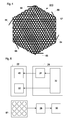
- Fig. 7 is a view showing the constitution of a detection coil 82 which can be used in the second embodiment.
- This detection coil 82 is constituted by fitting a plurality (nine in Fig. 7) of small coils 84a to 84i to one side of a substrate 83 made of resin, wood, glass, ceramic, ferrite or the like.
- These small coils 84a to 84i are connected in series in such a way that the directions of the winding of each two adjacent small coils become opposite to each other. Therefore, the magnetic flux directions of each two adjacent small coils 84a to 84i become opposite to each other.
- the magnetic flux direction of each small coil is expressed by a signal + or -, shown in the center of the small coil 84a to 84i.
- the detection coil 82 was provided above the cross coil 22. However, the detection coil 82 may be provided below the cross coil 22, as shown in Fig. 8. Further, the number of small coils is not restricted and may be one.
- Fig. 9 is a case of using, as a detection coil 82, one loop coil obtained by winding a conductor into a flat spiral shape. In this case, distorted signals are not taken out as a differential output; therefore, the accuracy of detection is a little low as compared with a case of taking out the distorted signals as a differential output.
- detection tags There were used detection tags whose detection distance had been adjusted to 10 mm. The detection distance was measured using gates for prevention of shoplifting, EG-C45 (a product of LINTEC CORPORATION).
- the above detection tag was moved parallel to the surface of detection coil at a speed of 0.5 m/sec and there was obtained decisions of the machine. From the result there was examined the detection accuracy of the decision machine of detection tag using magnetic field. The distance between the detection tag moved parallel to the surface of detection coil and that of detection coil was maintained at 15 mm.
- a first individual coil 46 was formed by winding an enamel-coated copper wire of 0.315 mm in diameter 255 times along the two opposing sides of a frame member of rectangular prism shape, made of flat wooden plate having a width of 120 mm, a depth of 120 mm and a height of 15 mm. Then, an enamel-coated copper wire of 0.315 mm in diameter was wound 255 times round the first individual coil 46 to form a second individual coil 50, in such a way that the central axes of the first individual coil 46 and the second individual coil 50 formed an angle of 90°. Thereby, a cross coil 22 was produced.
- the first individual coil 46 and the second individual coil 50 were supplied alternate currents of 306 Hz and 1.2 A, which differed in phase by 90°.
- the output signals from the two individual coils were subjected to Fourier transform at two signal processor parts 28a and 28b, as shown in Fig. 3. Of the frequency components obtained, harmonic components of 306 Hz (306 Hz x 2, 3, 4, ... ) were detected by a decision part 30. Based on the decision result, the deactivation or non-deactivation of detection tag was ascertained.
- a first individual coil 46 was formed by winding an enamel-coated copper wire of 0.5 mm in diameter 200 times along the two opposing sides of a frame member of rectangular prism shape, made of flat wooden plate having a width of 120 mm, a depth of 120 mm and a height of 30 mm. Then, an enamel-coated copper wire of 0.5 mm in diameter was wound 200 times round the first individual coil 46 to form a second individual coil 50, in such a way that the central axes of the first individual coil 46 and the second individual coil 50 formed an angle of 90°. Thereby, a cross coil 22 was produced.
- the first individual coil 46 and the second individual coil 50 were supplied alternate currents of 306 Hz and 1.2 A, which differed in phase by 90°.
- An enamel-coated copper wire of 0.2 mm in diameter was wound 60 times clockwise in a circular ring shape of 20 mm in diameter, to form nine cylindrical coils each having a height of 2 mm.
- These nine coils were arranged on a cork plate-made substrate 83 in three lengthwise rows and three crosswise rows (each row contained three coils) so that the center-to-center distance between two adjacent coils was 30 mm and the central axis directions of all the coils became parallel to one another. Further, all the coils were connected in series so that the current directions of each two adjacent coils became opposite to each other.
- the thus-produced detection coil 82 was provided in such a way that the lower side of each cylindrical coil was 10 mm apart from the upper surface of the cross coil 22, as shown in Fig. 6. In this case, the plane including the central axes of the individual coils 46 and 50 of the cross coil 22 and the substrate 83 having the detection coil 82 thereon are fitted parallel to each other.
- the detection coil 82 In the detection coil 82, the current directions of each two adjacent coils are opposite to each other; therefore, the detection coil 82 is a kind of differential circuit.
- the total current (signal) of all the nine coils was sent to a signal processor part 28 and subjected to Fourier transform for conversion into frequency components.
- the frequency components obtained included, besides the frequency component 306 Hz of the supplied AC power, harmonic components which were 2, 3, 4, ⁇ times of 306 Hz.
- the presence of such harmonic components was examined by a decision part 30. Based on the result, the deactivation or non-deactivation of detection tag was ascertained. The result is shown in Table 1.
- an enamel-coated copper wire of 0.28 mm in diameter was wound in a spiral shape 1,200 times to produce two circular planar coils 94a and 94b each of 120 mm in diameter.
- the two circular planar coils 94a and 94b were placed apart by 10 mm in a state that their central axes agreed with each other.
- the circular planar coils 94a and 94b there was constituted a decision machine of detection tag using magnetic field.
- the differential output of the currents of the two circular planar coils 94a and 94b was taken out and the signal was subjected to Fourier transform at a signal processor part 28.
- the presence in the frequency components obtained, of harmonic components (306 Hz x 2, 3, 4, ⁇ ) besides the frequency component 306 Hz of the supplied alternate current was examined at a decision part 30. Based on the result, the deactivation or non-deactivation of detection tag was ascertained. The result is shown in Table 1.
- a detection tag was allowed to enter the periphery or center of the upper side (detection surface) of a cross coil 22 or a circular planar coil, from the lengthwise direction (a direction parallel to the arrow Y of Fig. 1), the crosswise direction (a direction parallel to the arrow X of Fig. 1) or the oblique direction (a direction parallel to the arrow Z of Fig. 1). Thereby, the decision ability of the decision machine of detection tag using magnetic field was examined. The result is shown in Table 1.
Abstract
The present invention discloses a decision machine of detection tag (26) using magnetic field, comprising:
- a cross coil (22) constituted by a plurality of individual coils which have been wound round a frame member (42) so as to form a predetermined differential angle between the central axes of the individual coils,
- a magnetic power supply part (24) comprising an oscillator for generating an AC power and a phase modulator for differing each other the phase of AC power generated by the oscillator, by a predetermined differential angle, to supply powers of different phases to the individual coils,
- a signal processor part (28) connected to the plurality of individual coils, and
- a decision part (30) for deciding the output signal sent from the signal processor part.
Description
- The present invention relates to a decision machine of detection tag using magnetic field, used for confirmation of the deactivation of a magnetic detection tag (hereinafter referred to also as detection tag or EM tag). More particularly, the present invention relates to a decision machine of detection tag using magnetic field, which is used for confirming, after the deactivation operation of a detection tag, whether or not the detection tag has been deactivated reliably by a deactivation operation.
- Detection tags using a magnetic field as a detection means are known. They are attached to goods, etc., are carried with the goods and, when passing through particular gates, are detected by the gates; thereby, the circulation of goods is controlled and the theft of goods is prevented (Claim 1 of JP 1994-342065A). Such a detection tag using a magnetic field is also called EM (electric magnetic) tag.
- Fig. 12 shows a conventional detection tag. In Fig. 12, 160 is a soft magnetic substance layer containing cobalt, etc. On one side of the soft
magnetic substance layer 160 is laminated, via a polyester-basedadhesive layer 162, a hardmagnetic substance layer 165 having a large number of through-holes 163 formed therein. The hardmagnetic substance layer 165 contains a hard magnetic substance element(s) such as nickel or (and) the like. On the upper side of the hardmagnetic substance layer 165 is laminated aprotective layer 167 made of wood-free paper or a resin film. - On the other side of the soft
magnetic substance layer 160 is laminated arelease liner 169 via a pressure-sensitive adhesive layer 168. - In using this detection tag, the
release liner 169 is peeled and the release liner 169-removed detection tag is adhered to goods or the like to be controlled. - Fig. 13
shows gates gates gates gates - Incidentally, 174 is a detection tag. When the
detection tag 174 moves between thegates gates detection tag 174. By detecting this distortion of the magnetic field S using the detector (not shown), the passing of thedetection tag 174 between thegates - Fig. 14 shows a method for specifically detecting the distortion of magnetic field. In Fig. 14, (a1) shows the waveform of an alternating magnetic field of particular frequency formed between the
gates - In Fig. 14, (b1) shows the waveform of an alternating magnetic field which has been distorted by the passing of
detection tag 174 betweengates harmonics detection tag 174 betweengates - For example, when goods or the like purchased normally is in a state that it can be carried out, the
detection tag 174 adhered to the goods or the like is deactivated beforehand. Owing to this deactivation operation, there occurs no distortion of magnetic field when thedetection tag 174 adhered to the goods or the like is passed betweengates - Meanwhile, when the goods or the like is carried out illegally, the
detection tag 174 adhered thereto is in a state not deactivated. Therefore, when the goods or the like containing thedetection tag 174 not deactivated is passed betweengates - Deactivation of detection tag can be achieved by magnetizing the hard
magnetic substance layer 165 of detection tag shown in Fig. 12, using a deactivation machine. - Fig. 11 shows a deactivation machine used conventionally. This
deactivation machine 150 comprises asupport 152 and disc-shaped permanent magnets of 12 mm in diameter, arranged at intervals of about 10 mm. The permanent magnets are arranged so that anN pole 154 and aS pole 156 appear alternately. - When the detection tag shown in Fig. 12 touches on the upper surface of the
deactivation machine 150, the hardmagnetic substance layer 165 is magnetized and thereby the detection tag is deactivated. - In deactivating a detection tag by using a conventional deactivation machine, however, all the detection tags subjected to the deactivation are not always deactivated reliably and there are cases of no deactivation. In such cases, even the commodities purchased legally are detected at gates and are regarded as illegally purchased commodities, causing a big problem.
- In order to solve this problem, the present inventors proposed a deactivation machine comprising the above-mentioned deactivation machine using permanent magnets and a means for confirmation of deactivation, fitted thereto (Japanese Patent Application 2004-322700). This means for confirmation of deactivation comprises total two loop coils each having a function of generating a magnetic field and a function of detecting the reflected signal from a detection tag, and a signal-detecting circuit.
- In the means for confirmation of deactivation, the two loop coils generate magnetic fields. Any detection tag which has not been deactivated successfully, reflects the generated magnetic fields and the reflected signals are received by the two loop coils. The reflected signals received are taken out as a differential signal of the two loop coils and thereby the deactivation or non-deactivation of detection tag is confirmed.
- In the deactivation machine proposed above, it was found that the detectability of the means for confirmation of deactivation may be low depending upon the entering direction when a detection tag enters a deactivation surface (a surface at which magnets are arranged alternately). For example, the detection sensitivity for a detection tag entering the periphery of the deactivation surface may be low. In such a case, deactivation state of a detection tag subjected to deactivation operation may not be decided correctly.
- The present inventors made a study in order to solve the above problem and thought of a cross coil constituted by a plurality of coils for magnetic field generation which have been wound so as to form a predetermined differential angle between the central axes of the individual coils. By supplying AC powers of different phases to this cross coil, the magnetic field generated by the cross coil become uniform. As a result, variation of the detection sensitivity for detection tag, which occurs depending upon the entering site of detection tag, can be eliminated.
- The present invention has been completed based on the above finding. Accordingly, the present invention aims at providing a decision machine of detection tag using magnetic field, which can reliably confirm the deactivation of detection tag irrespectively of the entering site of detection tag.
- The present invention, which has achieved the above aim, is as described below.
- [1] A decision machine of detection tag using magnetic field, comprising:
- a cross coil constituted by a plurality of individual coils which have been wound round a frame member so as to form a predetermined differential angle between the central axes of the individual coils,
- a magnetic power supply part comprising an oscillator for generating an AC power and a phase modulator for differing each other the phase of AC power generated by the oscillator, by a predetermined differential angle, to supply powers of different phases to the individual coils,
- a signal processor part connected to the plurality of individual coils, and
- a decision part for deciding the output signal sent from the signal processor part.
- [2] The decision machine of detection tag using magnetic field, comprising:
- a cross coil constituted by a plurality of individual coils which have been wound round a frame member so as to form a predetermined differential angle between the central axes of the individual coils,
- a magnetic power supply part comprising an oscillator for generating an AC power and a phase modulator for differing each other the phase of AC power generated by the oscillator, by a predetermined differential angle, to supply powers of different phases to the individual coils,
- at least one detection coil provided parallel to a plane including the central axes of the individual coils,
- a signal processor part connected to the at least one detection coil, for processing the output signal of the detection coil, and
- a decision part for deciding the output signal sent from the signal processor part.
- [3] The decision machine of detection tag using magnetic field according to [2], wherein a plurality of detection coils are connected in series so that the magnetic flux directions of each adjacent detection coils become opposite to each other.
- [4] The decision machine of detection tag using magnetic field according to any of [1] to [3], wherein the cross coil is provided so that the magnetic flux directions of two adjacent individual coils differ by 90° and wherein the phases of the AC powers supplied to the individual coils are allowed to differ by 90°.
- In the decision machine of detection tag using magnetic field according to the present invention, there is used, as a coil for magnetic field generation, a cross coil constituted by a plurality of individual coils which have been wound so as to form a predetermined differential angle between the central axes of the individual coils. Therefore, a reduction in the detection sensitivity for detection tag, which occurs depending upon the entering site of detection tag, can be eliminated with no necessity of intensifying the electric current supplied to the coils. As a result, the deactivation of detection tag can be confirmed reliably. Thus, there can be reliably avoided a mistake by which a non-deactivated detection tag is detected at gates.
-
- Fig. 1 is a view showing an example of a cross coil used in the present invention. (a) is a plan view and (b) is a side view.
- Fig. 2 is a conceptual view showing an example of a constitution of the decision machine of detection tag using magnetic field, of the present invention.
- Fig. 3 is a block diagram showing an example of a circuit constitution of the decision machine of detection tag using magnetic field, of the present invention.
- Fig. 4 is a view showing other example of cross coil used in the present invention.
- Fig. 5 is a block diagram showing other example of circuit constitution of the decision machine of detection tag using magnetic field, of the present invention.
- Fig. 6 is a view showing an example of a constitution of the decision machine of detection tag using magnetic field, of Fig. 5.
- Fig. 7 is a view showing an example of a detection coil of the decision machine of detection tag using magnetic field, of Fig. 5.
- Fig. 8 is a view showing other example of the decision machine of detection tag using magnetic field, of the present invention.
- Fig. 9 is a view showing still other example of the decision machine of detection tag using magnetic field, of the present invention.
- Fig. 10 is a view showing the constitution of the decision machine of detection tag using magnetic field, of Comparative Example.
- Fig. 11 is a plan view showing a conventional deactivation machine.
- Fig. 12 is a side view showing an example of a constitution of the detection tag.
- Fig. 13 is a view showing a method for detection of detection tag.
- Fig. 14 is a view showing a principle of detection of detection tag. (a) shows the waveform of an alternating magnetic field generated between gates, and (b) show the waveform of an alternating magnetic field when a detection tag has been detected.
- In these drawings, 22 is a cross coil; 24 is a magnetic power supply part; 26 is a detection tag; 28, 28a and 28b are each a signal processor part; 30 is a decision part; 42 and 62 are each a frame member; 44, 48, 64, 66 and 68 are each a coated conductor.
- 46 is a first individual coil; X, Y and Z are each an arrow; 50 is a second individual coil; α is an angle formed by the central axes of individual coils; 32 is an oscillator; 34 is a phase modulator; 910 is a cross coil; 82 is a detection coil; 83 is a substrate; 84a to 84i are each a small coil; 94a and 94b are each a circular planar coil; 95 is a magnetic power supply part; and P is a differential output.
- Embodiments of the present invention are described in detail below with referring to the accompanying drawings.
- Fig. 2 is a conceptual view showing an example of a constitution of the decision machine of detection tag using magnetic field, of the present invention. In Fig. 2, 22 is a cross coil which has a characteristic structure of the present invention as described below.
- To the
cross coil 22 are supplied a plurality of AC powers of different phases from a magneticpower supply part 24. Owing to this supply of powers, an alternating magnetic field is formed along the surface of thecross coil 22. When adetection tag 26 is moved along the surface (the upper surface in Fig. 2) of thecross coil 22, the formed alternating magnetic field is distorted. This distorted alternating magnetic field is detected by thecross coil 22, and the detected signal is sent to asignal processor part 28 and subjected to predetermined signal processing. Then, the processed signal is sent to adecision part 30, where the deactivation or non-deactivation of thedetection tag 26 is ascertained. - Fig. 1(a) is a plan view showing an example of cross coil used in the above decision machine of detection tag using magnetic field, and Fig. 1(b) is a side view thereof. In Fig. 1, 22 is a cross coil. 42 is a flat plate-shaped frame member and is formed in a rectangular shape (a square in Fig. 1) with an insulating sheet made of a resin, wood, glass, ceramic, ferrite or the like. A
coated conductor 44 is wound round theframe member 42 along on of the opposing two sides, whereby a flat, firstindividual coil 46 is formed. Accordingly, the direction of the central axis of the firstindividual coil 46, i.e. the direction of the magnetic flux formed by the firstindividual coil 46 is the direction of an arrow X shown in Fig. 1(a). - A
coated conductor 48 is wound on the outer surface of the firstindividual coil 46 along the opposing two sides of theframe member 42 which are different from the above-mentioned two opposing sides, whereby a flat, secondindividual coil 50 is formed. Accordingly, the direction of the central axis of the secondindividual coil 50, i.e. the direction of the magnetic flux formed by the secondindividual coil 50 is the direction of an arrow Y shown in Fig. 1(a). Thus, the firstindividual coil 46 and the secondindividual coil 50 have respective central axes on the same plane and the angle α formed by the two central axes is 90°. - As to the size of the
cross coil 22, there is no particular restriction. The size may be such that, when thedetection tag 26 is moved along the upper surface of thecross coil 22, the deactivation of thedetection tag 26 can be ascertained magnetically. The movement distance of thedetection tag 26, necessary for magnetic ascertainment of the deactivation of thedetection tag 26 is preferred to be generally 30 mm or more and, from the standpoint of practical application, 30 to 100 mm. - Fig. 3 is a block diagram showing a circuit constitution of the above decision machine of detection tag using magnetic field. A magnetic
power supply part 24 is constituted by anoscillator 32 and aphase modulator 34. The AC power generated by theoscillator 32 is divided into two portions. One AC power portion is sent to thephase modulator 34; its phase is changed by thephase modulator 34 by 90° as compared with that of other AC power portion; the resulting AC power is supplied to a firstindividual coil 46. - A second
individual coil 50 is supplied the other AC power portion of the same phase generated by theoscillator 32. Therefore, the firstindividual coil 46 and the secondindividual coil 50 are supplied AC powers of different (by 90°) phases. As a result, the distribution of the magnetic field intensity above thecross coil 22 becomes highly uniform. Consequently, anynon-deactivated detection tag 26 which enters above the upper surface of thecross coil 22, can be detected reliably irrespectively of the entering site of thedetection tag 26. - The Alternating magnetic field above the
cross coil 22, which has been distorted by entering of thedetection tag 26, is detected by the firstindividual coil 46 and the secondindividual coil 50; the detected signals are sent to signalprocessor parts detection tag 26 is ascertained by adecision part 30. - Fig. 4 is other an example of
cross coil 910 used in the present invention. In thiscross coil 910, threecoated conductors - When the number of individual coils is n, the angle α formed by each two adjacent central axes of the individual coils is most preferably:

The angle α is not restricted to the above and may be:
because this angle functions with no substantial problem. - The magnetic field intensity generated by the individual coils is preferably 120 A/m or more at the detection site of detection tag and 150 to 250 A/m from the standpoint of practical application.
- Fig. 6 shows other embodiment of the present invention. In the first embodiment, the same cross coil performs a function of magnetic field generation and a function of detection of the magnetic field.
- In the second embodiment, a magnetic field is generated by a cross coil and the distortion of the magnetic field caused by a detection tag is detected by a detection coil which is different from the cross coil and provided separately.
- In Fig. 6, a
cross coil 22 is the same as described in the first embodiment. Above thiscross coil 22 is fitted adetection coil 82 adjacently to thecross coil 22. Incidentally, 26 is a detection tag. In the following drawings, the same numerals are given to the same constitution for simplicity of description. - Fig. 5 is a block diagram showing the electronic circuit of the decision machine of detection tag using magnetic field (second embodiment) shown in Fig. 6.
- In Fig. 5, AC powers of different (by 90°) phases are supplied from a magnetic
power supply part 24 to theindividual coils cross coil 22, whereby is formed a magnetic field above thecross coil 22. When, in this state, anon-deactivated detection tag 26 enters above thecross coil 22, the magnetic field is distorted. The principle up to this point is the same as in the first embodiment. - This distortion of magnetic field is detected by a
detection coil 82 provided above thecross coil 22; the detected signals are subjected to processings such as Fourier transform, filtration and the like at asignal processor part 28; then, the deactivation or non-deactivation of thedetection tag 26 is ascertained at adecision part 30. - Fig. 7 is a view showing the constitution of a
detection coil 82 which can be used in the second embodiment. Thisdetection coil 82 is constituted by fitting a plurality (nine in Fig. 7) ofsmall coils 84a to 84i to one side of asubstrate 83 made of resin, wood, glass, ceramic, ferrite or the like. Thesesmall coils 84a to 84i are connected in series in such a way that the directions of the winding of each two adjacent small coils become opposite to each other. Therefore, the magnetic flux directions of each two adjacentsmall coils 84a to 84i become opposite to each other. The magnetic flux direction of each small coil is expressed by a signal + or -, shown in the center of thesmall coil 84a to 84i. - As described above, by arranging a plurality of
small coils 84a to 84i, a large detection area is secured. Further, since the signals of distorted magnetic fields are taken as a differential output P of the individual small coils, external noises are cancelled, resulting in a higher detection accuracy. - In the above description, the
detection coil 82 was provided above thecross coil 22. However, thedetection coil 82 may be provided below thecross coil 22, as shown in Fig. 8. Further, the number of small coils is not restricted and may be one. - Fig. 9 is a case of using, as a
detection coil 82, one loop coil obtained by winding a conductor into a flat spiral shape. In this case, distorted signals are not taken out as a differential output; therefore, the accuracy of detection is a little low as compared with a case of taking out the distorted signals as a differential output. - There were produced decision machines of detection tag using magnetic field, described in the following Examples and Comparative Example, and they were examined for the decision ability of deactivation of detection tag.
- There were used detection tags whose detection distance had been adjusted to 10 mm. The detection distance was measured using gates for prevention of shoplifting, EG-C45 (a product of LINTEC CORPORATION).
- The above detection tag was moved parallel to the surface of detection coil at a speed of 0.5 m/sec and there was obtained decisions of the machine. From the result there was examined the detection accuracy of the decision machine of detection tag using magnetic field. The distance between the detection tag moved parallel to the surface of detection coil and that of detection coil was maintained at 15 mm.
- There was produced a decision machine of detection tag using magnetic field, having a constitution shown in Fig. 2. A first
individual coil 46 was formed by winding an enamel-coated copper wire of 0.315 mm in diameter 255 times along the two opposing sides of a frame member of rectangular prism shape, made of flat wooden plate having a width of 120 mm, a depth of 120 mm and a height of 15 mm. Then, an enamel-coated copper wire of 0.315 mm in diameter was wound 255 times round the firstindividual coil 46 to form a secondindividual coil 50, in such a way that the central axes of the firstindividual coil 46 and the secondindividual coil 50 formed an angle of 90°. Thereby, across coil 22 was produced. - The first
individual coil 46 and the secondindividual coil 50 were supplied alternate currents of 306 Hz and 1.2 A, which differed in phase by 90°. - The output signals from the two individual coils were subjected to Fourier transform at two
signal processor parts decision part 30. Based on the decision result, the deactivation or non-deactivation of detection tag was ascertained. - There was produced a decision machine of detection tag using magnetic field, having a constitution shown in Fig. 6.
- A first
individual coil 46 was formed by winding an enamel-coated copper wire of 0.5 mm in diameter 200 times along the two opposing sides of a frame member of rectangular prism shape, made of flat wooden plate having a width of 120 mm, a depth of 120 mm and a height of 30 mm. Then, an enamel-coated copper wire of 0.5 mm in diameter was wound 200 times round the firstindividual coil 46 to form a secondindividual coil 50, in such a way that the central axes of the firstindividual coil 46 and the secondindividual coil 50 formed an angle of 90°. Thereby, across coil 22 was produced. - The first
individual coil 46 and the secondindividual coil 50 were supplied alternate currents of 306 Hz and 1.2 A, which differed in phase by 90°. - An enamel-coated copper wire of 0.2 mm in diameter was wound 60 times clockwise in a circular ring shape of 20 mm in diameter, to form nine cylindrical coils each having a height of 2 mm. These nine coils were arranged on a cork plate-made
substrate 83 in three lengthwise rows and three crosswise rows (each row contained three coils) so that the center-to-center distance between two adjacent coils was 30 mm and the central axis directions of all the coils became parallel to one another. Further, all the coils were connected in series so that the current directions of each two adjacent coils became opposite to each other. - The thus-produced
detection coil 82 was provided in such a way that the lower side of each cylindrical coil was 10 mm apart from the upper surface of thecross coil 22, as shown in Fig. 6. In this case, the plane including the central axes of theindividual coils cross coil 22 and thesubstrate 83 having thedetection coil 82 thereon are fitted parallel to each other. - In the
detection coil 82, the current directions of each two adjacent coils are opposite to each other; therefore, thedetection coil 82 is a kind of differential circuit. The total current (signal) of all the nine coils was sent to asignal processor part 28 and subjected to Fourier transform for conversion into frequency components. The frequency components obtained included, besides the frequency component 306 Hz of the supplied AC power, harmonic components which were 2, 3, 4, ··· times of 306 Hz. The presence of such harmonic components was examined by adecision part 30. Based on the result, the deactivation or non-deactivation of detection tag was ascertained. The result is shown in Table 1. - As shown in Fig. 10, an enamel-coated copper wire of 0.28 mm in diameter was wound in a spiral shape 1,200 times to produce two circular planar coils 94a and 94b each of 120 mm in diameter. The two circular planar coils 94a and 94b were placed apart by 10 mm in a state that their central axes agreed with each other. Using the circular planar coils 94a and 94b, there was constituted a decision machine of detection tag using magnetic field.
- In this decision machine of detection tag using magnetic field, alternate currents each of 306 Hz and 0.2 A, having the same phase were sent from a magnetic
electric supply part 95 to the circular planar coils 94a and 94b, to generate an Alternating magnetic field. In this state, adetection tag 26 was allowed to enter the surface of the circular planar coil 94a horizontally with a distance of 15 mm kept between the detection tag and the surface of the circular planar coil 94a. - The differential output of the currents of the two circular planar coils 94a and 94b was taken out and the signal was subjected to Fourier transform at a
signal processor part 28. The presence in the frequency components obtained, of harmonic components (306 Hz x 2, 3, 4, ···) besides the frequency component 306 Hz of the supplied alternate current was examined at adecision part 30. Based on the result, the deactivation or non-deactivation of detection tag was ascertained. The result is shown in Table 1. - A detection tag was allowed to enter the periphery or center of the upper side (detection surface) of a
cross coil 22 or a circular planar coil, from the lengthwise direction (a direction parallel to the arrow Y of Fig. 1), the crosswise direction (a direction parallel to the arrow X of Fig. 1) or the oblique direction (a direction parallel to the arrow Z of Fig. 1). Thereby, the decision ability of the decision machine of detection tag using magnetic field was examined. The result is shown in Table 1.Table 1 Direction of tag entering Example 1 Example 2 Comparative Example Crosswise direction (X) Periphery D D N Center D D D Lengthwise direction (Y) Periphery D D N Center D D D Oblique direction (Z) Periphery D D N Center D D D D: There was detection of detection tag. N: There was no detection of detection tag.
Claims (4)
- A decision machine of detection tag using magnetic field, comprising:a cross coil constituted by a plurality of individual coils which have been wound round a frame member so as to form a predetermined differential angle between the central axes of the individual coils,a magnetic power supply part comprising an oscillator for generating an AC power and a phase modulator for differing each other the phase of AC power generated by the oscillator, by a predetermined differential angle, to supply powers of different phases to the individual coils,a signal processor part connected to the plurality of individual coils, anda decision part for deciding the output signal sent from the signal processor part.
- The decision machine of detection tag using magnetic field, comprising:a cross coil constituted by a plurality of individual coils which have been wound round a frame member so as to form a predetermined differential angle between the central axes of the individual coils,a magnetic power supply part comprising an oscillator for generating an AC power and a phase modulator for differing each other the phase of AC power generated by the oscillator, by a predetermined differential angle, to supply powers of different phases to the individual coils,at least one detection coil provided parallel to a plane including the central axes of the individual coils,a signal processor part connected to the at least one detection coil, for processing the output signal of the detection coil, anda decision part for deciding the output signal sent from the signal processor part.
- The decision machine of detection tag using magnetic field according to Claim 2, wherein a plurality of detection coils are connected in series so that the magnetic flux directions of each adjacent detection coils become opposite to each other.
- The decision machine of detection tag using magnetic field according to any of Claims 1 to 3, wherein the cross coil is provided so that the magnetic flux directions of two adjacent individual coils differ by 90° and wherein the phases of the AC powers supplied to the individual coils are allowed to differ by 90°.
Applications Claiming Priority (1)
| Application Number | Priority Date | Filing Date | Title |
|---|---|---|---|
| JP2005031266A JP2006220420A (en) | 2005-02-08 | 2005-02-08 | System for determining magnetic detection tag |
Publications (1)
| Publication Number | Publication Date |
|---|---|
| EP1688763A1 true EP1688763A1 (en) | 2006-08-09 |
Family
ID=36127298
Family Applications (1)
| Application Number | Title | Priority Date | Filing Date |
|---|---|---|---|
| EP06100934A Withdrawn EP1688763A1 (en) | 2005-02-08 | 2006-01-27 | Decision machine of detection tag using magnetic field |
Country Status (3)
| Country | Link |
|---|---|
| US (1) | US20060187054A1 (en) |
| EP (1) | EP1688763A1 (en) |
| JP (1) | JP2006220420A (en) |
Citations (7)
| Publication number | Priority date | Publication date | Assignee | Title |
|---|---|---|---|---|
| JPH06342065A (en) | 1993-03-12 | 1994-12-13 | Esselte Meto Internatl Gmbh | Electronic-article monitoring system and method |
| US5905435A (en) * | 1997-02-18 | 1999-05-18 | Sensormatic Electronics Corporation | Apparatus for deactivating magnetomechanical EAS markers affixed to magnetic recording medium products |
| WO1999039313A1 (en) * | 1998-01-30 | 1999-08-05 | Sensormatic Electronics Corporation | Eas marker deactivation device having core-wound energized coils |
| US6111507A (en) * | 1997-02-03 | 2000-08-29 | Sensormatic Electronics Corporation | Energizing circuit for EAS marker deactivation device |
| US6181249B1 (en) * | 1999-01-07 | 2001-01-30 | Sensormatic Electronics Corporation | Coil driving circuit for EAS marker deactivation device |
| JP2004322700A (en) | 2003-04-22 | 2004-11-18 | Toyota Motor Corp | Tire air pressure determination device |
| GB2415865A (en) * | 2004-07-02 | 2006-01-04 | Redcliffe Ltd | Arrangement of demagnetising coil pairs for EAS tag deactivation unit |
Family Cites Families (2)
| Publication number | Priority date | Publication date | Assignee | Title |
|---|---|---|---|---|
| US5397986A (en) * | 1991-11-01 | 1995-03-14 | Federal Labs Systems Lp | Metal detector system having multiple, adjustable transmitter and receiver antennas |
| US6011474A (en) * | 1998-04-28 | 2000-01-04 | Sensormatic Electronics Corporation | Multiple-use deactivation device for electronic article surveillance markers |
-
2005
- 2005-02-08 JP JP2005031266A patent/JP2006220420A/en active Pending
-
2006
- 2006-01-27 EP EP06100934A patent/EP1688763A1/en not_active Withdrawn
- 2006-02-06 US US11/348,083 patent/US20060187054A1/en not_active Abandoned
Patent Citations (7)
| Publication number | Priority date | Publication date | Assignee | Title |
|---|---|---|---|---|
| JPH06342065A (en) | 1993-03-12 | 1994-12-13 | Esselte Meto Internatl Gmbh | Electronic-article monitoring system and method |
| US6111507A (en) * | 1997-02-03 | 2000-08-29 | Sensormatic Electronics Corporation | Energizing circuit for EAS marker deactivation device |
| US5905435A (en) * | 1997-02-18 | 1999-05-18 | Sensormatic Electronics Corporation | Apparatus for deactivating magnetomechanical EAS markers affixed to magnetic recording medium products |
| WO1999039313A1 (en) * | 1998-01-30 | 1999-08-05 | Sensormatic Electronics Corporation | Eas marker deactivation device having core-wound energized coils |
| US6181249B1 (en) * | 1999-01-07 | 2001-01-30 | Sensormatic Electronics Corporation | Coil driving circuit for EAS marker deactivation device |
| JP2004322700A (en) | 2003-04-22 | 2004-11-18 | Toyota Motor Corp | Tire air pressure determination device |
| GB2415865A (en) * | 2004-07-02 | 2006-01-04 | Redcliffe Ltd | Arrangement of demagnetising coil pairs for EAS tag deactivation unit |
Also Published As
| Publication number | Publication date |
|---|---|
| US20060187054A1 (en) | 2006-08-24 |
| JP2006220420A (en) | 2006-08-24 |
Similar Documents
| Publication | Publication Date | Title |
|---|---|---|
| EP0354759B1 (en) | Electromagnetic identification system | |
| US5204526A (en) | Magnetic marker and reading and identifying apparatus therefor | |
| US3990065A (en) | Theft detection system | |
| CN1197310A (en) | Method and apparatus for detecting RFID tag signal | |
| EP0906583B1 (en) | Magnetic reading devices | |
| EP1064631B1 (en) | Eas marker deactivation device having core-wound energized coils | |
| JPH11509323A (en) | Improvements on magnetic tags or markers | |
| CN103258399A (en) | Marker for coding electric goods surveillance system | |
| CA2358163C (en) | Coil array for eas marker deactivation device | |
| EP1647829A1 (en) | Antenna for detecting magnetic field, and gate for detecting detection tag employing the antenna | |
| EP1688763A1 (en) | Decision machine of detection tag using magnetic field | |
| JP2002533853A (en) | Deactivated element shapes for microwave-magnetic EAS markers | |
| JP2002501235A (en) | Magnetic data tagging | |
| EP0962002B1 (en) | Apparatus for deactivating magnetomechanical eas markers affixed to magnetic recording medium products | |
| WO2004104612A1 (en) | Magnetic field generating system applicable to nuclear magnetic resonance device | |
| US20060139171A1 (en) | Method for reactivation of magnetic detection tag and machine for reactivation of magnetic detection tag | |
| GB2349050A (en) | Programmable magnetic data tag | |
| KR100484009B1 (en) | Magnetic sensing and reading device | |
| EP1437680A1 (en) | Magnetic data tagging | |
| JP2006133085A (en) | Lapse indicator | |
| JPH0311708A (en) | Magnetic material and manufacture thereof |
Legal Events
| Date | Code | Title | Description |
|---|---|---|---|
| PUAI | Public reference made under article 153(3) epc to a published international application that has entered the european phase |
Free format text: ORIGINAL CODE: 0009012 |
|
| AK | Designated contracting states |
Kind code of ref document: A1 Designated state(s): AT BE BG CH CY CZ DE DK EE ES FI FR GB GR HU IE IS IT LI LT LU LV MC NL PL PT RO SE SI SK TR |
|
| AX | Request for extension of the european patent |
Extension state: AL BA HR MK YU |
|
| AKX | Designation fees paid |
Designated state(s): DE FR GB |
|
| STAA | Information on the status of an ep patent application or granted ep patent |
Free format text: STATUS: THE APPLICATION IS DEEMED TO BE WITHDRAWN |
|
| 18D | Application deemed to be withdrawn |
Effective date: 20070210 |