EP1688114B1 - Disposable wearing article - Google Patents
Disposable wearing article Download PDFInfo
- Publication number
- EP1688114B1 EP1688114B1 EP04818525A EP04818525A EP1688114B1 EP 1688114 B1 EP1688114 B1 EP 1688114B1 EP 04818525 A EP04818525 A EP 04818525A EP 04818525 A EP04818525 A EP 04818525A EP 1688114 B1 EP1688114 B1 EP 1688114B1
- Authority
- EP
- European Patent Office
- Prior art keywords
- area
- article
- core
- leak
- portions
- Prior art date
- Legal status (The legal status is an assumption and is not a legal conclusion. Google has not performed a legal analysis and makes no representation as to the accuracy of the status listed.)
- Not-in-force
Links
Images


Classifications
-
- A—HUMAN NECESSITIES
- A61—MEDICAL OR VETERINARY SCIENCE; HYGIENE
- A61F—FILTERS IMPLANTABLE INTO BLOOD VESSELS; PROSTHESES; DEVICES PROVIDING PATENCY TO, OR PREVENTING COLLAPSING OF, TUBULAR STRUCTURES OF THE BODY, e.g. STENTS; ORTHOPAEDIC, NURSING OR CONTRACEPTIVE DEVICES; FOMENTATION; TREATMENT OR PROTECTION OF EYES OR EARS; BANDAGES, DRESSINGS OR ABSORBENT PADS; FIRST-AID KITS
- A61F13/00—Bandages or dressings; Absorbent pads
- A61F13/15—Absorbent pads, e.g. sanitary towels, swabs or tampons for external or internal application to the body; Supporting or fastening means therefor; Tampon applicators
- A61F13/45—Absorbent pads, e.g. sanitary towels, swabs or tampons for external or internal application to the body; Supporting or fastening means therefor; Tampon applicators characterised by the shape
- A61F13/49—Absorbent articles specially adapted to be worn around the waist, e.g. diapers
- A61F13/495—Absorbent articles specially adapted to be worn around the waist, e.g. diapers with faecal cavity
-
- A—HUMAN NECESSITIES
- A61—MEDICAL OR VETERINARY SCIENCE; HYGIENE
- A61F—FILTERS IMPLANTABLE INTO BLOOD VESSELS; PROSTHESES; DEVICES PROVIDING PATENCY TO, OR PREVENTING COLLAPSING OF, TUBULAR STRUCTURES OF THE BODY, e.g. STENTS; ORTHOPAEDIC, NURSING OR CONTRACEPTIVE DEVICES; FOMENTATION; TREATMENT OR PROTECTION OF EYES OR EARS; BANDAGES, DRESSINGS OR ABSORBENT PADS; FIRST-AID KITS
- A61F13/00—Bandages or dressings; Absorbent pads
- A61F13/15—Absorbent pads, e.g. sanitary towels, swabs or tampons for external or internal application to the body; Supporting or fastening means therefor; Tampon applicators
- A61F13/45—Absorbent pads, e.g. sanitary towels, swabs or tampons for external or internal application to the body; Supporting or fastening means therefor; Tampon applicators characterised by the shape
- A61F13/49—Absorbent articles specially adapted to be worn around the waist, e.g. diapers
- A61F13/494—Absorbent articles specially adapted to be worn around the waist, e.g. diapers characterised by edge leakage prevention means
Definitions
- the present invention relates to a disposable wearing article used for absorption and containment of bodily waste discharged thereon.
- the article comprises a liquid-pervious topsheet, a liquid-impervious backsheet, a pair of liquid-impervious leak-barrier sheets including stretchable elastic members extending in the longitudinal direction and contractibly attached thereto so as to bias the leak-barrier sheets to rise up above the topsheet under a contractile force of these elastic members and a liquid-absorbent core interposed between the top- and backsheets so as to extend on the front waist region and the crotch region.
- the rear waist is divided into a first area put aside toward the rear end portion and a second area put aside toward the crotch region and wherein a stiffness of the second area is lower than those of the first area and the crotch region and proximal portion of the leak-barrier sheets as well as longitudinal ends of the elastic members lie on the first area of the rear waist region (See PATENT DOCUMENT 1).
- the first area comprises the top- and backsheets and a band-like waist-surrounding elastic member interposed between these sheets.
- the proximal portions of the leak-barrier sheets are permanently bonded to the outer surface of the topsheet extending on the first area.
- a contractile force of the elastic members attached to the leak-barrier sheets pulls the first area toward the crotch region so that the first area comes above the crotch region in the thickness direction of the article.
- a difference in level appears between the crotch region and the first area and the second area forms a pocket opening toward the crotch region. Even if bodily waste spreads on the topsheet toward the rear end portion, such bodily waste is received by the pocket and thereby leak of bodily waste beyond the rear end portion can be prevented.
- the present invention is directed to a disposable wearing article comprising: front and rear end portions extending in a transverse direction; transversely opposite side portions; a front waist region; a rear waist region; a crotch region extending between said waist regions; a liquid-pervious topsheet; a liquid-impervious backsheet, a pair of liquid-impervious first leak-barrier sheets laid on said transversely opposite side portions so as to extend in a longitudinal direction wherein said first leak-barrier sheets respectively comprise proximal portions extending in the longitudinal direction between said front and rear end portions, distal portions extending in the longitudinal direction along said proximal portions and normally biased to rise up above said topsheet and fixed longitudinally opposite end portions laid on said front and rear end portions and collapsed in the transverse direction and wherein stretchable first elastic members extending in the longitudinal direction are contractibly attached to the distal portions of said first leak-barrier sheets; a liquid-absorbent core interposed between said top- and backsheets so as to extend from said crotch region
- the transversely middle zone of the second area formed with the through-hole contains no core and therefore a transverse flexural stiffness of the core lying in this second area is lower than a transverse flexural stiffness of the core lying in the crotch region and the first area.
- a basis weight, a density and a thickness dimension of the core are uniform in said crotch region, the first area and the second area.
- the second leak-barrier sheet may extend to straddle the pair of first leak-barrier sheets and the distal portion of the second leak-barrier sheet is permanently bonded along the transversely opposite side portions thereof to the distal portions of the first leak-barrier sheets.
- a transverse flexural stiffness value of the core lying in the crotch region and the first area is in a range of 9.4 to 28.2 mN as measured by the Gurley's Method and a transverse flexural stiffness value of the core lying in the second area is in a range of 5.5 to 16.5 mN as measured by the Gurley's Method.
- the distal portions of the first leak-barrier sheets respectively including the first elastic members exhibit a stretch stress in a range of 0.02 to 0.32 N at 90% stretched state.
- the second area of the rear waist region is partially bent under the contractile force of the first elastic members attached to the first leak-barrier sheets whereby the first area of the rear waist region is pulled toward the crotch region until the first area comes above the crotch region as viewed in the thickness direction of the article so that a difference in level appears between the crotch region and the first area and the second area forms at least one of the barrier extending in the thickness direction of the article and the pocket facing the crotch region.
- the second area forms the barrier, even if bodily waste discharged on the article put on the wearer's body spreads on the topsheet toward the rear end portion, the second area can function to prevent bodily waste from further spreading beyond the first area and leaking out from the article beyond the rear end portion of the article.
- the second area forms the pocket, even if bodily waste discharged on the article put on the wearer's body spreads on the topsheet toward the rear end portion, such bodily waste will be received by the pocket without further spreading beyond the first area and leaking out from the article beyond the rear end portion.
- the article according to the present invention ensures that bodily waste is absorbed by the core lying in the first and second areas without any anxiety that bodily waste might stay on the barrier and/or within the pocket and bodily waste might leak out from the pocket.
- the distal portion of this second leak-barrier sheet forms the barrier against bodily waste adapted to prevent bodily waste discharged on the article put on the wearer's body from leaking out from the article beyond the rear end portion even if bodily waste spreads beyond the barrier formed by the second area to the first area.
- the distal portion of the second leak-barrier sheet is spaced apart upward from the topsheet as the distal portions of the first leak-barrier sheets rise up above the topsheet. In this way, the distal portion of this second leak-barrier sheet reliably functions as the barrier adapted to prevent bodily waste from leaking out from the article beyond the rear end portion.
- the contractile force of the first elastic members causes the core to be bent only in the second area without being accompanied with irregular bending of the core in the first area as well as in the crotch region.
- the first area can be reliably pulled toward the crotch region and the barriers and/or the pocket can be reliably formed.
- the contractile force of the first elastic members are sufficiently exerted on the first area to pull this first area toward the crotch region so that the second area can reliably form the barriers and/or the pocket.
- Fig. 1 is a partially cutaway perspective view showing a disposable wearing article 10A and Fig. 2 is a plan view showing the article 10 of Fig. 1 as seen from the side of the topsheet 17.
- a transverse direction is indicated by an arrow L
- a longitudinal direction is indicated by an arrow M
- a thickness direction is indicated by an arrow N.
- Fig. 2 shows the article 10A as has been developed in the longitudinal direction as well as in the transverse direction against a contractile force of elastic members 36, 40, 43.
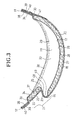
- Fig. 3 is a sectional view taken along the line 3-3 in Fig. 1
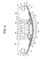
- Fig. 4 is is a sectional view taken along the line 4-4 in Fig. 1 and Fig.
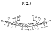
- FIG. 5 is a sectional view taken along the line 5-5 in Fig. 1 .
- expression “inner surfaces of the top- and backsheets 17, 18 and leak-barrier sheets 19” means the surfaces thereof facing a core 20 and expression “outer surfaces of these sheets 17, 18, 19” means the surfaces thereof facing away from the core 20.
- the article 10A is contoured by front and rear end portions 11, 12 extending in parallel to each other in the transverse direction and a pair of transversely opposite side portions 13 extending in the longitudinal direction. Between the front and rear end portions 11, 12, the article 10A has, as viewed in the longitudinal direction, a front waist region 14, a rear waist region 16 and a crotch region 15 extending between these waist regions 14, 16.
- the article 10A comprises a liquid-pervious topsheet 17 facing the wearer's skin, a liquid-impervious backsheet 18 facing away from the wearer's skin, a pair of liquid-impervious leak-barrier sheets 19 lying on the side portions 13 and extending in the longitudinal direction, and a liquid-absorbent core 20 interposed between the top- and backsheets 17, 18 and bonded to respective inner surfaces of these sheets17, 18.
- the core 20 extends continuously in the front and rear waist regions 14, 16 and the crotch region 15. In the crotch region 15, the transversely opposite side portions 13 curve inward as viewed in the transverse direction of the article 10A so as to describe circular arcs.
- the article 10A has a generally hourglass-like planar shape.
- An area 21 of the rear waist region 16 in which the core 20 is present is divided into a first area 22 put aside toward the rear end portion 12 and a second area 23 put aside toward the crotch region 15.
- the second area 23 is formed in its transversely middle zone 24 with a through-hole 25 extending through the core 20 in its thickness direction.
- the top- and backsheets 17, 18 are put flat together and have respective inner surfaces permanently bonded to each other.
- the topsheet 17 is formed from a hydrophilic fibrous nonwoven fabric 26.
- the backsheet 18 is formed from a composite sheet consisting of a breathable liquid-impervious plastic film 28 and a hydrophobic fibrous nonwoven fabric 27 laminated one upon another.
- the leak-barrier sheets 19 are formed from a repellent treated hydrophobic fibrous nonwoven fabric 29.
- the core 20 is contoured by longitudinally opposite ends 30 extending in the transverse direction and transversely opposite side edges 31 extending in the longitudinal direction.
- the core 20 comprises a mixture of particulate or fibrous super-absorbent polymer and fluff pulp or a mixture of particulate or fibrous super-absorbent polymers, fluff pulp fibers and thermoplastic synthetic resin fibers, in any case, compressed to a desired thickness. Therefore, the core 20 has a stiffness higher than those of top- and backsheets 17, 18 as well as of the leak-barrier sheets 19.
- the core 20 is entirely wrapped with a tissue paper (not shown) in order to prevent the core 20 from getting out of its initial shape.
- Basis weight and density as well as thickness dimension of the core 20 are uniform in the crotch region 15 and the first and second areas 22, 23.
- a transverse dimension of the core 20 in the second area 23 (inclusive of the through-hole 25) is the same as a transverse dimension of the core 20 in the crotch region 15 as well as in the first area 22.
- the core 20 preferably has a thickness dimension in a range of 1 to 10 mm.
- the core 20 has a transverse flexural stiffness lower in the second area 23 than in the crotch region 15 and the first area 22. This is because the second area 23 is formed in its transversely middle zone 24 with the through-hole 25 in which the core 20 is absent.
- the leak-barrier sheets 19 face the wearer's skin and are laid on the outer surface of the topsheet 17.
- the leak-barrier sheets 19 respectively comprise proximal portions 32 lying on the transversely opposite side portions 13 and extending in the longitudinal direction, distal portions 33 extending in the longitudinal direction along the proximal portions 32 and normally biased to rise up above the topsheet 17, and fixed longitudinally opposite end portions 34 lying on the front and rear end portions 11, 12 and collapsed inward as viewed in the transverse direction of the article 10A.
- the proximal portions 32 and the distal portions 33 extend between the front and rear end portions 11, 12 of the article 10A.
- the end portions 34 lying on the side of the rear waist region 16 are respectively laid not only on the rear end portion 12 but also on transversely opposite side portions 35 of the first area 22.
- Stretchable first elastic members 36 extending in the longitudinal direction are contractibly attached to the distal portions 33 in the vicinity of respective upper ends thereof.
- the elastic members 36 are stretched at a predetermined ratio in the longitudinal direction and permanently bonded in such a stretched state to the distal portions 33.
- Longitudinally ends 37 of the elastic members 36 extending into the rear waist region 16 extend beyond the second area 23 to the transversely opposite side portions 35 of the first area 22.
- the elastic members 36 contract as the article 10A curves in the longitudinal direction with the topsheet 17 inside.
- the distal portions 33 shrink in the longitudinal direction and rise up above the topsheet 17 under a contractile force of the elastic members 36.
- the distal portions 33 of the leak-barrier sheets 19 rise up above the topsheet 17 and form barriers against bodily waste discharged onto the article 10A.
- the front and rear end portions 11, 12 comprise respective end portions 38, 39 of the top- and backsheets 17, 18 extending outward in the longitudinal direction beyond the longitudinally opposite ends 30 of the core 20 and the end portions 34 of the respective leak-barrier sheets 19.
- the end portions 38, 39 of the top- and backsheets 17, 18 and the end portions 34 of the leak-barrier sheets 19 are put flat together wherein the respective inner surfaces of the top- and backsheets 17, 18 are permanently bonded to each other and the outer surface of the topsheet 17 is permanently bonded to the inner surfaces of the leak-barrier sheets 19.
- the end portions 34 of the leak-barrier sheets 19 have respective inner surfaces thereof are permanently bonded to the outer surface of the topsheet 17 in the vicinity of the transversely opposite side portions 35.
- Band-like waist-surrounding elastic members 40 extending in the transverse direction outside the longitudinally opposite ends 30 are contractibly attached to the front and rear end portions 11, 12.
- the waist-surrounding elastic members 40 are interposed between the end portions 38 of the topsheet 17 and the end portions 39 of the backsheet 18 and permanently bonded to the respective inner surfaces of these sheets 17, 18 while the elastic members 40 are stretched at a predetermined ratio in the transverse direction.
- the transversely opposite side portions 13 comprise the side portions 41, 42 of the top- and backsheets 17, 18 extending outward in the transverse direction beyond the side edges 31 of the core 20 and the proximal portions 32 of the respective leak-barrier sheets 19.
- the side portions 41 of the topsheet 17 extend outward in the transversely direction slightly beyond the side edges 31 of the core 20 and the side portions 42 of the backsheet 18 as well as the proximal portions 32 of the leak-barrier sheets 19 extend further outward in the transverse direction beyond the side portions 41 of the topsheet 17.
- the side portions 41, 42 of the top- and backsheets 17, 18 are put flat together with the proximal portions 32 of the leak-barrier sheets 19, and the inner surfaces of the top- and backsheets 17, 18 are permanently bonded together and the inner/outer surfaces of the top- and backsheets17, 18, respectively, and the inner surfaces of the respective leak-barrier sheets 19 are permanently bonded together.
- a plurality of leg-surrounding elastic members 43 lying outside the side edges 31 of the core 20 as viewed in the transverse direction and extending in the longitudinal direction are contractibly attached to the side portions 13. These leg-surrounding elastic members 43 are interposed between the side portions 41 of the topsheet 17 and the side portions 42 of the backsheet 18 and permanently bonded to the inner surfaces of the sheets 17, 18 while the elastic members 43 are stretched in the longitudinal direction at a predetermined ratio.
- Each of the tape fasteners 44 has a proximal end portion 45 extending in the transverse direction and a distal end portion 46.
- the proximal end portion 45 is interposed between the side portion 42 of the backsheet 18 and the proximal portion 32 of the leak-barrier sheet 19 and permanently bonded to the respective inner surfaces of the sheets 18, 19.
- the distal end portion 46 is provided with a hook member (not shown).
- the distal end portions 46 are folded inward in the transverse direction of the article 10A and temporarily fixed to the proximal portions 32 of the leak-barrier sheets 19 by means of the hook members. It is possible to replace the hook members 64 provided on the respective distal end portions 63 by pressure-sensitive adhesive protected by a release paper.
- a flexible target tape strip 47 is attached to the front waist region 14 so that the distal end portions 46 of the respective tape fasteners 44 may be detachably anchored on this target tape strip 47.
- the target tape strip 47 has a rectangular shape which is relatively long in the transverse direction, and comprises a plastic film and a loop member (not shown) attached to the film.
- the film constituting the target tape strip 47 is permanently bonded to the outer surface of the backsheet 18.
- a plastic film may be used as the target tape strip 47 provided with no loop member thereon.
- the article 10A may be put on the wearer's body by folding the side portions 13 of the rear waist region 16 onto the outer side of the side portions 13 of the front waist region 14 and then anchoring the distal end portions 46 of the respective tape fasteners 44 on the target tape strip 47 to connect the front and rear waist regions 14, 16 to each other.
- the article 10A is formed with a waist-hole and a pair of leg-holes (not shown).
- the second area 23 of the rear waist region 16 is partially folded under a contractile force of the elastic members 36 attached to the leak-barrier sheets 19 and the first area 22 is pulled toward the crotch region 15 so that the first area 22 comes above the crotch region 15 in the thickness direction of the article 10A.
- a difference in level appears between the crotch region 15 and the first area 22 in the thickness direction with interposition of the second area 23 which forms, in turn, a pocket 49 defined between a barrier 48 extending in the thickness direction of the article 10A and the crotch region 15.
- the barrier 48 forms not only the barrier 48 but also the pocket 49 so that bodily waste flowing toward the rear end portion 12 is received by the pocket 49. In this way, there is no anxiety that bodily waste might leak out beyond the rear end portion 12.
- the second area 23 of the article 10A is formed in the transversely middle zone 24 with the through-hole 25 extending through the core 20 in its thickness direction and a difference in level depending on the thickness dimension of the core 20 appears between the middle zone 24 and the side zones 50.
- the core 20 in the crotch region 15 and the first area 22 has a transverse flexural stiffness in a range of 9.4 to 28.2 mN and the core 20 which is present in the second area 23 has a transverse flexural stiffness in a range of 5.5 to 16.5 mN. If the flexural stiffness of the core 20 lying in the crotch region 15 and the first area 22 is less than 9.4 mN, the contractile force of the elastic members 36 may result in irregular bending of the crotch region 15 and the first area 22.
- Such irregular bending causes a gap to be left between the crotch region 15 and the first area 22, on one hand, and the wearer's skin, on the other hand, and makes it impossible for the core 20 lying in the crotch region 15 and first area 22 to absorb bodily waste efficiently. If the flexural stiffness of the core 20 lying in the crotch region 15 and first area 22 exceeds 28.2 mN, the flexural stiffness of these crotch region 15 and first area 22 will excessively increase and a feeling to the article 10A will be correspondingly created.
- the second area 23 may be irregularly bent under the contractile force of the elastic members 36 and it may be impossible for the second area 23 to form the barrier 48 and the pocket 49. If the flexural stiffness of the core 20 lying in the second area 23 exceeds 16.5 mN, it may be difficult for the core 20 lying in the second area 23 to be bent properly and it may be impossible for the first area 22 to be pulled toward the crotch region 15 under the contractile force of the elastic members 36. Eventually it may be impossible for the second area 23 to form the barrier 48 and the pocket 49.
- the flexural stiffness of the core 20 lying in the crotch region 15, the first area 22 and the second area 23 was measured by the Gurley Method (JIS L 1096-01-8.20.1) according to the procedures as follow:
- the flexural stiffness value of the first and third samples having been measured in this manner is in a range of 9.4 to 28.2 mN and the flexural stiffness value of the second sample having been measured in this manner is in a range of 5.5 to 16.5 mN.
- the second sample is formed in its transversely middle zone with the through-hole 25 in which the core 20 is absent and exhibited the flexural stiffness value correspondingly lower than the flexural stiffness value of the first and third samples.
- the distal portions 33 of the respective leak-barrier sheets 19 including the elastic members 36 have a stretch stress in a range of 0.02 to 32 N at 90% stretched state.
- the elastic members 36 are permanently bonded to the distal portions 33 of the leak-barrier sheets 19 and therefore the contractile force of these elastic members 36 is restrained by the stiffness of the distal portions 33.
- the stretch stress of the distal portions 33 in the above-described range allows the contractile force of the elastic members 36 to pull the first area 22 of the rear waist region 16 toward the crotch region 15.
- the stretch stress of the distal portions 33 is less than 0.02 N, the contractile force of the elastic members 36 will be too low to pull the first area 22 toward the crotch region 15 and consequently neither the barrier 48 nor the pocket 49 can be formed by the second area 23. If the stretch stress of the distal portions 33 exceeds 0.32 N, the first area 22 may be collapsed toward the crotch region 15 and the pocket 49 formed by the second area 23 may be closed.
- the stretch stress of the distal portions 33 of the respective leak-barrier sheets 19 was measured by the following method.
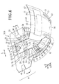
- Fig. 6 is a partially cutaway perspective view showing a disposable wearing article 10B
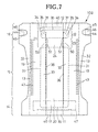
- Fig. 7 is a plan view showing the article 10B of Fig. 6 as seen from the side of the topsheet
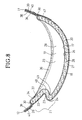
- Fig. 8 is a sectional view taken along the line 8-8 in Fig. 6
- Fig. 9 is a sectional view taken along the line 9-9 in Fig. 6
- a transverse direction is indicated by an arrow L
- a longitudinal direction is indicated by an arrow M
- a thickness direction is indicated by an arrow N.
- the article 10B is shown as has been developed in the longitudinal direction as well as in the transverse direction against a contractile force of elastic members 36, 40.
- the article 10B is contoured by front and rear end portions 11, 12 extending in parallel to each other in the transverse direction and a pair of side portions 13 extending in the longitudinal direction. Between the front and rear end portions 11, 12, the article 10B has a front waist region 14, a rear waist region 16 and a crotch region 15 extending between these waist regions 14, 16.
- the article 10B comprises a liquid-pervious topsheet 17 facing the wearer's skin, a liquid-impervious backsheet 18 facing away from the wearer's skin, a pair of liquid-impervious leak-barrier sheets 19 lying on the side portions 13 and extending in the longitudinal direction, and a liquid-absorbent core 20 interposed between the top- and backsheets 17, 18 and bonded to respective inner surfaces of these sheets17, 18.
- the core 20 extends continuously in the front and rear waist regions 14, 16 and the crotch region 15. In the crotch region 15, the side portions 13 curve inward as viewed in the transverse direction of the article 10B so as to describe circular arcs.
- the article 10B has a generally hourglass-like planar shape.
- An area 21 of the rear waist region 16 in which the core 20 is present is divided into a first area 22 put aside toward the rear end portion 12 and a second area 23 put aside toward the crotch region 15.
- the core 20 is partially cut away to form a pair of notches 51 which are concave inward as viewed in the transverse direction.
- the notches 51 are covered with the top and backsheets 17, 18 having respective inner surfaces permanently bonded to each other.
- the topsheet 17 is formed from a hydrophilic fibrous nonwoven fabric 26 and the backsheet 18 is formed from a composite sheet and the leak-barrier sheets 19 are formed from a hydrophobic fibrous nonwoven fabric 29.
- the core 20 also comprises the same mixture as that in the article 1A and extends continuously in the front waist region 14, the crotch region 15 and the rear waist region 16.
- the core 20 is contoured by longitudinally opposite ends extending in the transverse direction and transversely opposite side edges extending in the longitudinal direction.
- Basis weight and density as well as thickness dimension of the core 20 are uniform in the crotch region 15 and the first and second areas 22, 23.
- a transverse dimension of the core 20 lying in the second area 23 (inclusive of the notches 51) is the same as a transverse dimension of the core 20 lying in the crotch region 15 as well as in the first area 22.
- the core 20 has a transverse flexural stiffness lower in the second area 23 than in the crotch region 15 and the first area 22. This is because the second area 23 is formed in its transversely side zones 24 with the notches 51 in which the core 20 is absent.
- the leak-barrier sheets 19 respectively comprise proximal portions 32 lying on the side portions 13 and extending in the longitudinal direction, distal portions 33 extending in the longitudinal direction along the proximal portions 32 and normally biased to rise up above the topsheet 17, and fixed longitudinally opposite end portions 34 lying on the front and rear end portions 11, 12 and collapsed inward as viewed in the transverse direction of the article 10B.
- the end portions 34 lying on the side of the rear waist region 16 are respectively laid not only on the rear end portion 12 but also on transversely opposite side portions 35 of the first area 22.
- Stretchable first elastic members 36 extending in the longitudinal direction are contractibly attached to the distal portions 33 in the vicinity of respective upper ends thereof.
- the elastic members 36 are stretched at a predetermined ratio in the longitudinal direction and permanently bonded in such a stretched state to the distal portions 33.
- Longitudinally ends 37 of the elastic members 36 extending into the rear waist region 16 extend beyond the second area 23 to the side portions 35 of the first area 22.
- the elastic members 36 contract as the article 10B curves in the longitudinal direction with the topsheet 17 inside.
- the distal portions 33 shrink in the longitudinal direction and rise up above the topsheet 17 under a contractile force of the elastic members 36.
- the distal portions 33 of the leak-barrier sheets 19 form barriers against bodily waste discharged onto the article 10B.
- the front and rear end portions 11, 12 comprise respective end portions 38, 39 of the top- and backsheets 17, 18 extending outward in the longitudinal direction beyond the longitudinally opposite ends 30 of the core 20 and the end portions 34 of the respective leak-barrier sheets 19.
- the end portions 34, 38, 39 of the sheets 17, 18, 19 are put flat together wherein the respective inner surfaces of the top- and backsheets 17, 18 are permanently bonded to each other and the outer surface of the topsheet 17 is permanently bonded to the inner surfaces of the leak-barrier sheets 19.
- the end portions 34 of the leak-barrier sheets 19 have respective inner surfaces thereof are permanently bonded to the outer surface of the topsheet 17 in the vicinity of the side portions 35.
- Band-like waist-surrounding elastic members 40 extending in the transverse direction outside the longitudinally opposite ends 30 are contractibly attached to the front and rear end portions 11, 12.
- the transversely opposite side portions 13 comprise the side portions 41, 42 of the top- and backsheets 17, 18 extending outward in the transverse direction beyond the side edges 31 of the core 20 and the proximal portions 32 of the respective leak-barrier sheets 19.
- the side portions 41 of the topsheet 17 extend outward in the transversely direction slightly beyond the side edges 31 of the core 20 and the side portions 42 of the backsheet 18 as well as the proximal portions 32 of the leak-barrier sheets 19 extend further outward in the transverse direction beyond the side portions 41 of the topsheet 17.
- the proximal portions 32, 41, 42 of the sheets 17, 18, 19 are put flat together and the inner surfaces of the top- and backsheets 17, 18 are permanently bonded together and the inner/outer surfaces of the top- and backsheets 17, 18, respectively, and the inner surfaces of the respective leak-barrier sheets 19 are permanently bonded together.
- a plurality of leg-surrounding elastic members 43 extending in the longitudinal direction are contractibly attached to the side portions 13.
- Flexible tape fasteners 44 made of a fibrous nonwoven fabric are respectively attached to the side portions 13 of the rear waist region 16.
- the proximal end portion 45 is interposed between the side portion 42 of the backsheet 18 and the proximal portion 32 of the leak-barrier sheet 19 and permanently bonded to the respective inner surfaces of these sheets 18, 19.
- the distal end portion 46 is provided on its inner surface with a hook member (not shown) .
- the target tape strip 47 comprises a plastic film and a loop member (not shown) attached to the film. Procedures for putting the article 10B on the wearer's body is the same as in the case of the article 10A and detailed description thereof is eliminated here.
- the second area 23 is partially folded and the first area 22 is pulled toward the crotch region 15 under a contractile force of the elastic members 36 attached to the leak-barrier sheets 19 so that the first area 22 comes above the crotch region 15 in the thickness direction of the article 10B.
- a difference in level appears between the crotch region 15 and the first area 22 in the thickness direction and the second area 23 forms a pocket 49 defined between a barrier 48 extending in the thickness direction of the article 10B and the crotch region 15.
- the barrier 48 forms a pocket 49 the barrier 48 but also the pocket 49 so that bodily waste flowing toward the rear end portion 12 is received by the pocket 49. In this way, there is no anxiety that bodily waste might leak out beyond the rear end portion 12.
- the core 20 is partially cut away to form a pair of notches 51 which are concave inward as viewed in the transverse direction and a difference in level depending on the thickness dimension of the core 20 appears between the middle zone 24 and the side zones 50.
- the transversely opposite side zones 50 is prevented by the thickness of the core 20 which is present in the transversely middle zone 24 from being collapsed. This is because the transversely middle zone 24 containing the core 20 is folded upon itself before the transversely opposite middle zones 24 of the second area 23 might be folded upon each other.
- the core 20 lying in the crotch region 15 and the first area 22 has a transverse flexural stiffness in a range of 9.4 to 28.2 mN and the core 20 which is present in the second area 23 has a flexural stiffness in a range of 5.5 to 16.5 mN. If the flexural stiffness of the core 20 lying in the crotch region 15 and the first area 22 is less than 9.4 mN, the contractile force of the elastic members 36 may result in irregular bending of the crotch region 15 and the first area 22. Such irregular bending will make it impossible for the core 20 lying in the crotch region 15 and first area 22 to absorb bodily waste efficiently.
- the flexural stiffness of the core 20 lying in the crotch region 15 and first area 22 exceeds 28.2 mN, the flexural stiffness of the crotch region 15 and first area 22 will excessively increase and a feeling to wear the article 10B will be correspondingly created. If the flexural stiffness of the core 20 lying in the second area 23 is less than 5.5 mN, the second area 23 may be irregularly bent under the contractile force of the elastic members 36 and it may be impossible for the second area 23 to form the barrier 48 and the pocket 49.
- the flexural stiffness of the core 20 lying in the second area 23 exceeds 16.5 mN, it may be difficult for the core 20 lying in the second area 23 to be bent properly and it may be impossible to for the first area 22 to be pulled toward the crotch region 15 under the contractile force of the elastic members 36. Eventually it may be impossible for the second area 23 to form the barrier 48 and the pocket 49.
- the flexural stiffness value of the core 20 lying in the crotch region 15 as well as the first and second area 22, 23 was measured by the Gurley Method (in accordance with JIS L 1096-01-8.20.1). This measuring method for the flexural stiffness was the same as in the article 10A. As a sample of the core 20 lying in the second area 23 was the second sample having the core 20 partially cut off to form a pair of notches 51 and its flexural stiffness value was correspondingly lower than the flexural stiffness value of the first and second samples.
- the distal portions 33 of the respective leak-barrier sheets 19 including the elastic members 36 have a stretch stress in a range of 0.02 to 32 N at a 90% stretched state.
- the elastic members 36 are permanently bonded to the distal portions 33 of the leak-barrier sheets 19 and therefore the contractile force of the elastic members 36 is restrained by the stiffness of the distal portions 33.
- the stretch stress of the distal portions 33 in the above-described range allows the contractile force of the elastic members 36 to pull the first area 22 of the rear waist region 16 toward the crotch region 15.
- the stretch stress of the distal portions 33 is less than 0.02 N, the contractile force of the elastic members 36 will be too low to pull the first area 22 toward the crotch region 15 and consequently neither the barrier 48 nor the pocket 49 can be formed by the second area 23. If the stretch stress of the distal portions 33 exceeds 0.32 N, the first area 23 may be collapsed toward the crotch region 15 and the pocket 49 formed by the second area 23 may be closed.
- the stretch stress of the distal portions 23 of the respective leak-barrier sheets 19 was measured by the following method.
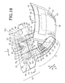
- Fig. 10 is a partially cutaway perspective view showing a disposable wearing article 10C as a preferred embodiment of the invention
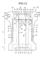
- Fig. 11 is a plan view showing the article 10C as seen from the side of the topsheet 17
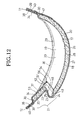
- Fig. 12 is a sectional view taken along the line 12-12 in Fig. 10
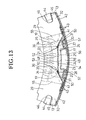
- Fig. 13 is a sectional view taken along the line 13-13 in Fig. 10
- a transverse direction is indicated by an arrow L
- a longitudinal direction is indicated by an arrow
- a thickness direction is indicated by an arrow N.
- Fig. 11 is a plan view showing the article 10C as has been developed the longitudinal direction as well as in the transverse direction against a contractile force of elastic members 36, 40, 43, 56.
- the article 10C is contoured by a pair of longitudinally opposite end portions 11, 12 extending in parallel to each other in the transverse direction and a pair of transversely opposite side portions 13 extending in the longitudinal direction. Between the front and rear end portions 11, 12, the article 10C has a front waist region 14, a rear waist region 16 and a crotch region 15 extending between these waist regions 14, 16.
- the article 10C comprises a liquid-pervious topsheet 17 facing the wearer's skin, a liquid-impervious backsheet 18 facing away from the wearer's skin, a pair of liquid-impervious leak-barrier sheets 19 lying on the side portions 13 and extending in the longitudinal direction, and a liquid-absorbent core 20 interposed between the top- and backsheets 17, 18 and bonded to respective inner surfaces of the sheets 17, 18.
- the core 20 extends continuously in the front and rear waist regions 14, 16 and the crotch region 15. In the crotch region 15, the side portions 13 curve inward as viewed in the transverse direction of the article 10C so as to describe circular arcs.
- the article 10C has a generally hourglass-like planar shape.
- An area 21 of the rear waist region 16 in which the core 20 is present is divided into a first area 22 put aside toward the rear end portion 12 and a second area 23 put aside toward the crotch region 15.
- the second area 23 is formed in its transversely middle zone 24 with a through-hole 25 extending through the core 20 in its thickness direction.
- the top- and backsheets 17, 18 are put flat together and have respective inner surfaces permanently bonded to each other.
- the topsheet 17 is formed by a hydrophilic fibrous nonwoven fabric 26 and the backsheet 18 is formed by a composite sheet and the leak-barrier sheets 19 are formed from a hydrophobic fibrous nonwoven fabric 29.
- the core 20 also comprises the same mixture as that in the article 10A and extends continuously in the front waist region 14, the crotch region 15 and the rear waist region 16.
- the core 20 is contoured by longitudinally opposite ends extending in the transverse direction and transversely opposite side edges extending in the longitudinal direction.
- Basic weight and density as well as thickness dimension of the core 20 are uniform in the crotch region 15 and the first and second areas 22, 23.
- a transverse dimension of the core 20 lying in the second area 23 (inclusive of the through-hole 25) is same as a transverse dimension of the core 20 lying in the crotch region 15 as well as in the first area 22.
- the core 20 has a transverse flexural stiffness lower in the second area 23 than in the crotch region 15 and the first region 22. This is because the second area 23 I formed in its transversely middle zone 24 with the through-hole 25 in which the core 20 is absent.
- the leak-barrier sheets 19 respectively comprise proximal portions 32 lying on the side portions 13 and extending in the longitudinal direction, distal portions 33 extending in the longitudinal direction along the proximal portions 32 and normally biased to rise up above the topsheet 17, and fixed longitudinally opposite end portions 34 lying on the front and rear end portions 11, 12 and collapsed inward as viewed in the transverse direction of the article 10C.
- the end portions 34 lying on the side of the rear waist region 16 are respectively laid not only on the rear end portion 12 but also on transversely opposite side portions 35 of the first area 22.
- Stretchable first elastic members 36 extending in the longitudinal direction are contractibly attached to the distal portions 33 in the vicinity of respective upper ends thereof.
- the elastic members 36 are stretched at a predetermined ratio in the longitudinal direction and permanently bonded in such a stretched state to the distal portions 33.
- Longitudinally ends 37 of the elastic members 36 extending into the rear waist region 16 extend beyond the second area 23 to the side portions 35 of the first area 22.
- the elastic members 36 contract as the article 10C curves in the longitudinal direction with the topsheet 17 inside.
- the distal portions 33 shrink in the longitudinal direction and rise up above the topsheet 17 under a contractile force of the elastic members 36.
- the distal portions 33 of the leak-barrier sheets 19 form barriers against bodily waste discharged onto the article 10C.
- a second leak-barrier sheet 52 is laid so as to straddle the first leak-barrier sheets 19.
- the leak-barrier sheet 52 comprises a proximal portion 53 lying in the first area 22 and extending in the transverse direction, a distal portion 54 extending in the transverse direction from the first area 22 to the second area along the proximal portion 53 and transversely opposite side proximal portions 55 lying on the side portions 13 of the article 10C and collapsed inward as viewed in the longitudinal direction.
- a stretchable second elastic member 56 extending in the transverse direction is contractibly attached to the distal portion 54 in the vicinity of its upper edge. This elastic member 56 is permanently bonded to the distal portion 54 while the elastic member 56 is stretched in the transverse direction at a predetermined ratio.
- Transversely opposite lateral zones 57 of the distal portion 54 are permanently bonded to the distal portions 33 of the first leak-barrier sheets 19.
- the proximal portions 55 are interposed between the end portions 38 of the topsheet 17 and the end portions 34 of the first leak-barrier sheets 19 and the inner/outer surfaces of the respective end portions 34, 38 of the sheets 17, 19.
- the distal portion 54 of the leak-barrier sheet 52 is spaced apart upward from the topsheet 17 as the distal portions 33 of the leak-barrier sheets 19 rise up above the topsheet 17.
- the distal portion 54 also forms a barrier adapted to prevent bodily waste from spreading in the longitudinal direction.
- the front and rear end portions 11, 12 comprise respective end portions 38, 39 of the top- and backsheets 17, 18 extending outward in the longitudinal direction beyond the longitudinally opposite ends 30 of the core 20 and the end portions 34 of the respective leak-barrier sheets 19.
- the end portions 34, 38, 39 of the sheets 17, 18, 19 are put flat together wherein the respective inner surfaces of the top- and backsheets 17, 18 are permanently bonded to each other and the outer surface of the topsheet 17 is permanently bonded to the inner surfaces of the leak-barrier sheets 19.
- the end portions 34 of the leak-barrier sheets 19 have respective inner surfaces thereof are permanently bonded to the outer surface of the topsheet 17 in the vicinity of the side portions 35.
- Band-like waist-surrounding elastic members 40 extending in the transverse direction outside the longitudinally opposite ends 30 are contractibly attached to the front and rear end portions 11, 12.
- the side portions 13 comprise the side portions 41, 42 of the top- and backsheets 17, 18 extending outward in the transverse direction beyond the side edges 31 of the core 20 and the proximal portions 32 of the respective leak-barrier sheets 19.
- the side portions 41 of the topsheet 17 extend outward in the transversely direction slightly beyond the side edges 31 of the core 20 and the side portions 42 of the backsheet 18 as well as the proximal portions 32 of the leak-barrier sheets 19 extend further outward in the transverse direction beyond the side portions 41 of the topsheet 17.
- the proximal portions 32, 41, 42 of the sheets 17, 18, 19 are put flat together and the inner surfaces of the top- and backsheets 17, 18 are permanently bonded together and the inner/outer surfaces of the top- and backsheets17, 18, respectively, and the inner surfaces of the respective leak-barrier sheets 19 are permanently bonded together.
- a plurality of leg-surrounding elastic members 43 extending in the longitudinal direction are contractibly attached to the side portions 13.
- Flexible tape fasteners 44 made of a fibrous nonwoven fabric are respectively attached to the side portions 13 of the rear waist region 16.
- the proximal end portion 45 is interposed between the side portion 42 of the backsheet 18 and the proximal portion 32 of the leak-barrier sheet 19 and permanently bonded to the respective inner surfaces of the sheets 18, 19.
- the distal end portion 46 is provided on its inner surface with a hook member (not shown).
- the target tape strip 47 comprises a plastic film and a loop member (not shown) attached to the film. Procedures for putting the article 10C on the wearer's body is the same as in the case of the article 10A and detailed description thereof is eliminated here.
- the second area 23 is partially folded and the first area 22 is pulled toward the crotch region 15 under a contractile force of the elastic members 36 attached to the leak-barrier sheets 19 so that the first area 22 comes above the crotch region 15 in the thickness direction of the article 10B,
- difference in level appears between the crotch region 15 and the first area 22 in the thickness direction and the second area 23 forms a pocket 49 defined between a barrier 48 extending in the thickness direction of the article 10B and the crotch region 15.
- the barrier 48 forms a pocket 49 the barrier 48 but also the pocket 49 so that bodily waste flowing toward the rear end portion 12 is received by the pocket 49. In this way, there is no anxiety that bodily waste might leak out beyond the rear end portion 12.
- the second area 23 of the article 10C is formed in the transversely middle zone 24 with the through-hole 25 extending through the core 20 in its thickness direction and a difference in level depending on the thickness dimension of the core 20 appears between the middle zone 24 and the side zones 50.
- the distal portion 54 of the second leak-barrier sheet 52 forms a barrier against bodily waste and, even bodily waste discharged on the article 10C put on the wearer's body flows beyond the barriers 48 to the first area 22, such bodily waste is prevented by the distal portion 54 of the leak-barrier sheet 52 from further flowing.
- the distal portion 54 of the second leak-barrier sheet 52 is permanently bonded along the transversely opposite side portions 57 thereof to the distal portions 33 of the first leak-barrier sheets 19.
- the distal portion 54 is spaced apart upward from the topsheet 17 as the distal portions 33 rise up above the topsheet 17 and therefore the distal portion 54 of the second leak-barrier sheet 52 adequately functions as the barrier adapted to prevent bodily waste from leaking out beyond the rear end portion 12.
- the core 20 lying in the crotch region 15 and the first area 22 has a transverse flexural stiffness in a range of 9.4 to 28.2 mN and the core 20 which is present in the second area 23 has a flexural stiffness in a range of 5.5 to 16.5 mN. If the flexural stiffness of the core 20 lying in the crotch region 15 and the first area 22 is less than 9.4 mN, the contractile force of the elastic members 36 may result in irregular bending of the crotch region 15 and the first area 22. Such irregular bending will make it impossible for the core 20 lying in the crotch region 15 and first area 22 to absorb bodily waste efficiently.
- the flexural stiffness of the core 20 lying in these crotch region 15 and first area 22 exceeds 28.2 mN, the flexural stiffness of these crotch region 15 and first area 22 will excessively increase and a feeling to wear the article 10C will be correspondingly created. If the flexural stiffness of the core 20 lying in the second area 23 is less than 5.5 mN, the second area 23 may be irregularly bent under the contractile force of the elastic members 36 and it may be impossible for the second area 23 to form the barrier 48 and the pocket 49.
- the flexural stiffness of the core 20 lying in the second area 23 exceeds 16.5 mN, it may be difficult for the core 20 lying in the second area 23 to be bent properly and it may be impossible for the first area 22 to be pulled toward the crotch region 15 under the contractile force of the elastic members 36. Eventually it may be impossible for the second area 23 to form the barrier 48 and the pocket 49.
- the flexural stiffness of the core 20 lying in the crotch region 15, the first area 22 and the second area 23 was measured by the Gurley Method (JIS L 1096-01-8.20.1). The method for measuring the flexural stiffness was same as the method used for the article 10A.
- the distal portions 33 of the respective leak-barrier sheets 19 including the elastic members 36 have a stretch stress in a range of 0.02 to 32 N at a 90% stretched state. If the stretch stress of the distal portions 33 is less than 0.02 N, the contractile force of the elastic members 36 will be too low to pull the first area 22 toward the crotch region 15 and consequently neither the barrier 48 nor the pocket 49 can be formed by the second area 23. If the stretch stress of the distal portions 33 exceeds 0.32 N, the first area 22 may be collapsed toward the crotch region 15 and the pocket 49 formed by the second area 23 may be closed. The stretch stress of the distal portions 33 of the respective leak-barrier sheets 19 was measured by the same method as the method used for the article 10A.
- the second area 23 forms the barrier 48 extending in the thickness direction of the article 10A, 10B, 10C and the pocket 49 facing the crotch region 15 in the article 10A, 10B, 10C described herein as specific embodiments, it may be contemplated within the scope of the invention that, depending on a stretch stress of the elastic members 36, the second area 23 can form only one of the barrier 48 and the pocket 49.
- the first area 22 is insufficiently pulled toward the crotch region 15 under a contractile force of the elastic members 36
- the second area 23 tilts toward the rear end portion 12 and formed the barrier 48 alone.
- the first area 22 is pulled beyond the second area 23 to the crotch region 15 under a contractile force of the elastic members 36, the second area 23 tilts toward the crotch region 15 and forms the pocket 49 alone.
- Stock materials for the topsheet 17 is not limited to the hydrophilic fibrous nonwoven fabric but may be also selected from the group consisting of a hydrophobic fibrous nonwoven fabric having a plurality of perforations and a plastic film having a plurality of fine apertures. Without departing from the scope of the invention, it is possible to form the backsheet 18 using any one selected from the group consisting of a hydrophobic fibrous nonwoven fabric, a breathable liquid-impervious plastic film and a composite nonwoven fabric comprising two or more layers of hydrophobic fibrous nonwoven fabric laminated one upon another.
- SM nonwoven fabric SMS nonwoven fabric or SMMS nonwoven fabric
- SM nonwoven fabric consisting of a melt blown fibrous nonwoven fabric having a high water-resistance and a spun bond fibrous nonwoven fabric being high in strength as well as in flexibility laminated on at least one side of the melt blown fibrous nonwoven fabric.
- Stock materials for the fibrous nonwoven fabric layers may be selected from the group consisting of spun lace-, needle punch-, melt blown-, thermal bond-, spun bond- and chemical bond-nonwoven fabric layers.
- Component fibers of these nonwoven fabric layers may be selected from the group consisting of polyester-, polyacrylonitril-, polyvinyl chloride-, polyethylene-, polypropylene- and polystyrene-based fibers. It is also possible without departing from the scope of the invention to use the component fibers selected from the group consisting of core-sheath conjugate fibers, side-by-side conjugate fibers, modified macaroni fibers, microporous fibers and fused type conjugate fibers.
- Permanently bonding of the top- and backsheets 17, 18 to each other, permanently bonding of the leak-barrier sheets 19, 52 to the sheets 17, 18, bonding of the core 20 to the sheets 17, 18 and permanently bonding of the elastic members 37, 41, 44, 56 to the sheets 17, 18, 19, 52 may be achieved by using adhesive or welding technique such as heat-sealing or sonic sealing.
- Adhesive may be selected from the group consisting of hot melt adhesive, acrylic adhesive and rubber-based adhesive.
- the adhesive is coated on the topsheet 17, the backsheet 18 and the leak-barrier sheets 19, 52 preferably in any one of spiral, wavy, zigzag, dotted or striped pattern.
- the sheets 17, 18, 19, 52 may be coated with adhesive in such patterns to define adhesive-coated regions and adhesive-free regions in these sheets 17, 18, 19, 52 and thereby to ensure that the sheets 17, 18, 19, 52 are intermittently and permanently bonded one to another, the core 20 is intermittently and permanently bonded to the sheets 17, 18 and the elastic members 37, 41, 44, 56 are intermittently and permanently bonded to the sheets 17, 18, 19, 52.
Abstract
Description
- The present invention relates to a disposable wearing article used for absorption and containment of bodily waste discharged thereon.
- There has already been disclosed a disposable wearing article contoured by front and rear end portions extending in a transverse direction and transversely opposite lateral portions, the front and rear end portions defining therebetween a front waist region, a rear waist region and a crotch region extending between the waist regions. The article comprises a liquid-pervious topsheet, a liquid-impervious backsheet, a pair of liquid-impervious leak-barrier sheets including stretchable elastic members extending in the longitudinal direction and contractibly attached thereto so as to bias the leak-barrier sheets to rise up above the topsheet under a contractile force of these elastic members and a liquid-absorbent core interposed between the top- and backsheets so as to extend on the front waist region and the crotch region. The rear waist is divided into a first area put aside toward the rear end portion and a second area put aside toward the crotch region and wherein a stiffness of the second area is lower than those of the first area and the crotch region and proximal portion of the leak-barrier sheets as well as longitudinal ends of the elastic members lie on the first area of the rear waist region (See PATENT DOCUMENT 1).
- The first area comprises the top- and backsheets and a band-like waist-surrounding elastic member interposed between these sheets. The proximal portions of the leak-barrier sheets are permanently bonded to the outer surface of the topsheet extending on the first area. In the known article, a contractile force of the elastic members attached to the leak-barrier sheets pulls the first area toward the crotch region so that the first area comes above the crotch region in the thickness direction of the article. Thereupon a difference in level appears between the crotch region and the first area and the second area forms a pocket opening toward the crotch region. Even if bodily waste spreads on the topsheet toward the rear end portion, such bodily waste is received by the pocket and thereby leak of bodily waste beyond the rear end portion can be prevented.
- PATENT DOCUMENT 1: Japanese Unexamined Patent Application Publication No.
2001-61888 - In the case of the article disclosed in
PATENT DOCUMENT 1, there is an anxiety that the pocket might be collapsed when a body weight of the wearer is exerted on the rear waist region of the article put on the wearer's body and, in consequence, bodily waste might leak out from the pocket and eventually might leak beyond the first area and the rear end portion from the article. The core is not present in the first and second areas, so it is impossible for the first area and the second area forming the pocket to absorb bodily waste. Bodily waste staying in the pocket will readily leak out from the pocket as the pocket is collapsed. - It is an object of the present invention to provide a disposable wearing article improved so that a collapse-resistant pocket can be formed in the rear waist region, bodily waste can be absorbed even in the barrier as well as in the pocket and leakage of bodily waste beyond the rear end portion can be reliably prevented.
- The present invention is directed to a disposable wearing article comprising: front and rear end portions extending in a transverse direction; transversely opposite side portions; a front waist region; a rear waist region; a crotch region extending between said waist regions; a liquid-pervious topsheet; a liquid-impervious backsheet, a pair of liquid-impervious first leak-barrier sheets laid on said transversely opposite side portions so as to extend in a longitudinal direction wherein said first leak-barrier sheets respectively comprise proximal portions extending in the longitudinal direction between said front and rear end portions, distal portions extending in the longitudinal direction along said proximal portions and normally biased to rise up above said topsheet and fixed longitudinally opposite end portions laid on said front and rear end portions and collapsed in the transverse direction and wherein stretchable first elastic members extending in the longitudinal direction are contractibly attached to the distal portions of said first leak-barrier sheets; a liquid-absorbent core interposed between said top- and backsheets so as to extend from said crotch region into said front and rear waist regions; and an area of said rear waist region in which said core extends is divided into a first area lying on a side of said rear end portion and a second area lying on a side of said crotch region; said article being characterized in that:said second area is formed in a transversely middle zone thereof with a through-hole extending through said core in the thickness direction so that a flexural stiffness of said core is lower than in said first area of said rear waist region; said proximal portions of said first leak-barrier sheets as well as longitudinal end portions of said first elastic members lie in said first area of said rear waist region; and said first area is pulled to said crotch region and thereby said first area comes above said crotch region as viewed in a thickness direction of said article and said second area forms at least one of a barrier extending in a thickness direction of said article and a pocket facing said crotch region; and said article further comprises a liquid-impervious second leak-barrier sheet comprising a proximal portion lying in the first area of said rear waist region and extending in the transverse direction, a distal portion extending along said proximal portion in the transverse direction from the first area to the second area of said rear waist region and fixed transversely opposite side portions lying on a side of the transversely opposite side portions of said article and collapsed inward as viewed in the longitudinal direction and wherein a stretchable second elastic member extending in the transverse direction is contractibly attached to the free portion of said second leak-barrier sheet.
- The transversely middle zone of the second area formed with the through-hole contains no core and therefore a transverse flexural stiffness of the core lying in this second area is lower than a transverse flexural stiffness of the core lying in the crotch region and the first area.
- According to a preferred embodiment of the invention, a basis weight, a density and a thickness dimension of the core are uniform in said crotch region, the first area and the second area.
The second leak-barrier sheet may extend to straddle the pair of first leak-barrier sheets and the distal portion of the second leak-barrier sheet is permanently bonded along the transversely opposite side portions thereof to the distal portions of the first leak-barrier sheets.
According to another preferred embodiment of the invention, a transverse flexural stiffness value of the core lying in the crotch region and the first area is in a range of 9.4 to 28.2 mN as measured by the Gurley's Method and a transverse flexural stiffness value of the core lying in the second area is in a range of 5.5 to 16.5 mN as measured by the Gurley's Method.
According to still another additional preferred embodiment of the invention, the distal portions of the first leak-barrier sheets respectively including the first elastic members exhibit a stretch stress in a range of 0.02 to 0.32 N at 90% stretched state. - In the article according to the present invention, the second area of the rear waist region is partially bent under the contractile force of the first elastic members attached to the first leak-barrier sheets whereby the first area of the rear waist region is pulled toward the crotch region until the first area comes above the crotch region as viewed in the thickness direction of the article so that a difference in level appears between the crotch region and the first area and the second area forms at least one of the barrier extending in the thickness direction of the article and the pocket facing the crotch region. Assumed that the second area forms the barrier, even if bodily waste discharged on the article put on the wearer's body spreads on the topsheet toward the rear end portion, the second area can function to prevent bodily waste from further spreading beyond the first area and leaking out from the article beyond the rear end portion of the article. Assumed that the second area forms the pocket, even if bodily waste discharged on the article put on the wearer's body spreads on the topsheet toward the rear end portion, such bodily waste will be received by the pocket without further spreading beyond the first area and leaking out from the article beyond the rear end portion. In this way, the article according to the present invention ensures that bodily waste is absorbed by the core lying in the first and second areas without any anxiety that bodily waste might stay on the barrier and/or within the pocket and bodily waste might leak out from the pocket.
- In the case of the article wherein the second area is formed in its transversely middle zone with a through-hole extending through the core in the thickness direction, a difference in level appears between the transversely opposite side zones and the transversely middle zone of the second area depending on a differential thickness dimension of the core. With such an arrangement, even when a body weight of the wearer is exerted on the rear waist region and thereby the second area is compressed in the thickness direction of the article, the transversely middle zone is prevented by the thickness of the core present in the transversely opposite lateral zones from being collapsed. This is because the transversely opposite side zones in which the core is present are respectively folded upon themselves before the transversely middle zone might be folded upon itself. Even if the pocket is collapsed in the transversely opposite side zones of the second area, there is no possibility that the pocket might be collapsed in the transversely middle zone. Thus the pocket can be kept in the opened state so far as the transversely middle zone is concerned, so it is unlikely that bodily waste might leak out from the pocket and further leak out from the article beyond the rear end portion even when a body weight of the wearer is exerted on the rear waist region. Bodily waste is reliably absorbed by the core lying in the first area and the transversely opposite lateral zones of the second area without staying on the barrier and/or in the pocket.
- In the case of the article wherein a basis weight, a density and a thickness dimension of the core are uniform in the crotch region, the first area and the second area and wherein the core is formed with the through-hole, it is unlikely that the core lying in the first area and the crotch region might be irregularly bent under a contractile force of the first elastic members attached to the first leak-barrier sheets. Consequently, the core lying in the second area can be reliably bent and thereby the first area can be reliably pulled toward the crotch region. In addition, there is no anxiety that the core might become locally bulky and locally increased stiffness of the core might create a feeling of discomfort against the wearer.
- In the case of the article wherein the article includes a liquid-impervious second leak-barrier sheet lying in the rear waist region and extending in the transverse direction, the distal portion of this second leak-barrier sheet forms the barrier against bodily waste adapted to prevent bodily waste discharged on the article put on the wearer's body from leaking out from the article beyond the rear end portion even if bodily waste spreads beyond the barrier formed by the second area to the first area.
- In the case of the article wherein the second leak-barrier sheet extends to straddle the pair of first leak-barrier sheets and the free portion of the second leak-barrier sheet is permanently bonded along the transversely opposite side portions thereof to the distal portions of the first leak-barrier sheets, the distal portion of the second leak-barrier sheet is spaced apart upward from the topsheet as the distal portions of the first leak-barrier sheets rise up above the topsheet. In this way, the distal portion of this second leak-barrier sheet reliably functions as the barrier adapted to prevent bodily waste from leaking out from the article beyond the rear end portion.
- In the case of the article wherein a transverse flexural stiffness value of the core lying in the crotch region and the first area is in a range of 9.4 to 28.2 mN as measured by the Gurley's Method and a transverse flexural stiffness value of the core lying in the second area is in a range of 5.5 to 16.5 mN as measured by the Gurley's Method, the contractile force of the first elastic members causes the core to be bent only in the second area without being accompanied with irregular bending of the core in the first area as well as in the crotch region. As a result, the first area can be reliably pulled toward the crotch region and the barriers and/or the pocket can be reliably formed.
- In the case of the article wherein the distal portions of the first leak-barrier sheets respectively including the first elastic members exhibit a stretch stress in a range of 0.02 to 0.32 N at 90% stretched state, the contractile force of the first elastic members are sufficiently exerted on the first area to pull this first area toward the crotch region so that the second area can reliably form the barriers and/or the pocket.
-
- [
FIG. 1] Fig. 1 is a partially cutaway perspective view showing a disposable diaper which is outside the scope of the appended claims. - [
FIG. 2] Fig. 2 is a plan view showing the article ofFig. 1 as seen from the side of the topsheet. - [
FIG. 3] Fig. 3 is a sectional view taken along the line 3-3 inFig. 1 . - [
FIG. 4] Fig. 4 is a sectional view taken along the line 4-4 inFig. 1 . - [
FIG. 5] Fig. 5 is a sectional view taken along the line 5-5 inFig. 1 . - [
FIG. 6] Fig. 6 is a partially cutaway perspective view showing a disposable wearing article which is outside the scope of the appended claims. - [
FIG. 7] Fig. 7 is a plan view showing the article ofFig. 6 as seen from the side of the topsheet. - [
FIG. 8] Fig. 8 is a sectional view taken along the line 8-8 inFig. 6 . - [
FIG. 9] Fig. 9 is a sectional view taken along the line 9-9 inFig. 6 . - [
FIG. 10] Fig. 10 is a partially cutaway perspective view showing a disposable wearing article as a preferred embodiment of the invention. - [
FIG. 11] Fig. 11 is a plan view showing the article ofFig. 10 as seen from the side of the topsheet. - [
FIG. 12] Fig. 12 is a sectional view taken along the line 12-12 inFig. 10 . - [
FIG. 13] Fig. 13 is a sectional view taken along the line 13-13 inFig. 10 . -
- 10A
- disposable wearing article
- 10B
- disposable wearing article
- 10C
- disposable wearing article
- 11
- front end portion
- 12
- rear end portion
- 13
- transversely opposite side portion
- 14
- front waist region
- 15
- crotch region
- 16
- rear waist region
- 17
- liquid-pervious topsheet
- 18
- liquid-impervious backsheet
- 19
- liquid-impervious first leak-barrier sheet
- 20
- liquid-absorbent core
- 21
- area
- 22
- first area
- 23
- second area
- 24
- transversely lateral zone
- 25
- through-hole
- 32
- proximal portion
- 33
- distal portion
- 34
- fixed longitudinally opposite end portion
- 35
- transversely opposite side portion
- 36
- stretchable first elastic member
- 37
- longitudinally end portion
- 48
- barrier
- 49
- 50
- transversely opposite side zone
- 51
- notch
- 52
- liquid-impervious second leak-barrier sheet
- 53
- proximal portion
- 54
- distal portion
- 55
- fixed transversely opposite side portion
- 56
- stretchable second elastic member
- 57
- transversely opposite lateral zone
- Details of a disposable wearing article according to the present invention will be more fully understood from the description given hereunder with reference to the accompanying drawings.
-
Fig. 1 is a partially cutaway perspective view showing a disposable wearingarticle 10A
andFig. 2 is a plan view showing the article 10 ofFig. 1 as seen from the side of thetopsheet 17. InFig. 1 , a transverse direction is indicated by an arrow L, a longitudinal direction is indicated by an arrow M and a thickness direction is indicated by an arrow N.Fig. 2 shows thearticle 10A as has been developed in the longitudinal direction as well as in the transverse direction against a contractile force ofelastic members Fig. 3 is a sectional view taken along the line 3-3 inFig. 1 ,Fig. 4 is is a sectional view taken along the line 4-4 inFig. 1 andFig. 5 is a sectional view taken along the line 5-5 inFig. 1 . As used herein, expression "inner surfaces of the top- andbacksheets barrier sheets 19" means the surfaces thereof facing acore 20 and expression "outer surfaces of thesesheets core 20. - The
article 10A is contoured by front andrear end portions opposite side portions 13 extending in the longitudinal direction. Between the front andrear end portions article 10A has, as viewed in the longitudinal direction, afront waist region 14, arear waist region 16 and acrotch region 15 extending between thesewaist regions article 10A comprises a liquid-pervious topsheet 17 facing the wearer's skin, a liquid-impervious backsheet 18 facing away from the wearer's skin, a pair of liquid-impervious leak-barrier sheets 19 lying on theside portions 13 and extending in the longitudinal direction, and a liquid-absorbent core 20 interposed between the top- andbacksheets core 20 extends continuously in the front andrear waist regions crotch region 15. In thecrotch region 15, the transverselyopposite side portions 13 curve inward as viewed in the transverse direction of thearticle 10A so as to describe circular arcs. Thus thearticle 10A has a generally hourglass-like planar shape. - An
area 21 of therear waist region 16 in which thecore 20 is present is divided into afirst area 22 put aside toward therear end portion 12 and asecond area 23 put aside toward thecrotch region 15. Thesecond area 23 is formed in itstransversely middle zone 24 with a through-hole 25 extending through the core 20 in its thickness direction. In a range defined by the through-hole 25, the top- andbacksheets - The
topsheet 17 is formed from a hydrophilic fibrousnonwoven fabric 26. Thebacksheet 18 is formed from a composite sheet consisting of a breathable liquid-impervious plastic film 28 and a hydrophobic fibrousnonwoven fabric 27 laminated one upon another. The leak-barrier sheets 19 are formed from a repellent treated hydrophobic fibrousnonwoven fabric 29. - The
core 20 is contoured by longitudinally opposite ends 30 extending in the transverse direction and transversely opposite side edges 31 extending in the longitudinal direction. Thecore 20 comprises a mixture of particulate or fibrous super-absorbent polymer and fluff pulp or a mixture of particulate or fibrous super-absorbent polymers, fluff pulp fibers and thermoplastic synthetic resin fibers, in any case, compressed to a desired thickness. Therefore, thecore 20 has a stiffness higher than those of top- andbacksheets barrier sheets 19. Preferably, thecore 20 is entirely wrapped with a tissue paper (not shown) in order to prevent the core 20 from getting out of its initial shape. - Basis weight and density as well as thickness dimension of the core 20 are uniform in the
crotch region 15 and the first andsecond areas crotch region 15 as well as in thefirst area 22. The core 20 preferably has a thickness dimension in a range of 1 to 10 mm. In spite of the fact that the basis weight and the density as well as the thickness dimension of the core 20 are uniform in thecrotch region 15 and the first andsecond areas core 20 has a transverse flexural stiffness lower in thesecond area 23 than in thecrotch region 15 and thefirst area 22. This is because thesecond area 23 is formed in itstransversely middle zone 24 with the through-hole 25 in which thecore 20 is absent. - The leak-
barrier sheets 19 face the wearer's skin and are laid on the outer surface of thetopsheet 17. The leak-barrier sheets 19 respectively compriseproximal portions 32 lying on the transverselyopposite side portions 13 and extending in the longitudinal direction,distal portions 33 extending in the longitudinal direction along theproximal portions 32 and normally biased to rise up above thetopsheet 17, and fixed longitudinallyopposite end portions 34 lying on the front andrear end portions article 10A. Theproximal portions 32 and thedistal portions 33 extend between the front andrear end portions article 10A. Theend portions 34 lying on the side of therear waist region 16 are respectively laid not only on therear end portion 12 but also on transverselyopposite side portions 35 of thefirst area 22. - Stretchable first
elastic members 36 extending in the longitudinal direction are contractibly attached to thedistal portions 33 in the vicinity of respective upper ends thereof. Theelastic members 36 are stretched at a predetermined ratio in the longitudinal direction and permanently bonded in such a stretched state to thedistal portions 33. Longitudinally ends 37 of theelastic members 36 extending into therear waist region 16 extend beyond thesecond area 23 to the transverselyopposite side portions 35 of thefirst area 22. Theelastic members 36 contract as thearticle 10A curves in the longitudinal direction with thetopsheet 17 inside. Thereupon thedistal portions 33 shrink in the longitudinal direction and rise up above thetopsheet 17 under a contractile force of theelastic members 36. As will be seen inFig. 1 , thedistal portions 33 of the leak-barrier sheets 19 rise up above thetopsheet 17 and form barriers against bodily waste discharged onto thearticle 10A. - The front and
rear end portions respective end portions backsheets core 20 and theend portions 34 of the respective leak-barrier sheets 19. Along the front andrear end portions end portions backsheets end portions 34 of the leak-barrier sheets 19 are put flat together wherein the respective inner surfaces of the top- andbacksheets topsheet 17 is permanently bonded to the inner surfaces of the leak-barrier sheets 19. In therear waist region 16, theend portions 34 of the leak-barrier sheets 19 have respective inner surfaces thereof are permanently bonded to the outer surface of thetopsheet 17 in the vicinity of the transverselyopposite side portions 35. Band-like waist-surroundingelastic members 40 extending in the transverse direction outside the longitudinally opposite ends 30 are contractibly attached to the front andrear end portions elastic members 40 are interposed between theend portions 38 of thetopsheet 17 and theend portions 39 of thebacksheet 18 and permanently bonded to the respective inner surfaces of thesesheets elastic members 40 are stretched at a predetermined ratio in the transverse direction. - The transversely
opposite side portions 13 comprise theside portions backsheets core 20 and theproximal portions 32 of the respective leak-barrier sheets 19. Along theside portions 13, theside portions 41 of thetopsheet 17 extend outward in the transversely direction slightly beyond the side edges 31 of thecore 20 and theside portions 42 of thebacksheet 18 as well as theproximal portions 32 of the leak-barrier sheets 19 extend further outward in the transverse direction beyond theside portions 41 of thetopsheet 17. Along the transverselyopposite side portions 13, theside portions backsheets proximal portions 32 of the leak-barrier sheets 19, and the inner surfaces of the top- andbacksheets barrier sheets 19 are permanently bonded together. A plurality of leg-surroundingelastic members 43 lying outside the side edges 31 of the core 20 as viewed in the transverse direction and extending in the longitudinal direction are contractibly attached to theside portions 13. These leg-surroundingelastic members 43 are interposed between theside portions 41 of thetopsheet 17 and theside portions 42 of thebacksheet 18 and permanently bonded to the inner surfaces of thesheets elastic members 43 are stretched in the longitudinal direction at a predetermined ratio. -
Flexible tape fasteners 44 made of a fibrous nonwoven fabric are respectively attached to theside portions 13 of therear waist region 16. Each of thetape fasteners 44 has aproximal end portion 45 extending in the transverse direction and adistal end portion 46. Theproximal end portion 45 is interposed between theside portion 42 of thebacksheet 18 and theproximal portion 32 of the leak-barrier sheet 19 and permanently bonded to the respective inner surfaces of thesheets distal end portion 46 is provided with a hook member (not shown). Thedistal end portions 46 are folded inward in the transverse direction of thearticle 10A and temporarily fixed to theproximal portions 32 of the leak-barrier sheets 19 by means of the hook members. It is possible to replace the hook members 64 provided on the respective distal end portions 63 by pressure-sensitive adhesive protected by a release paper. - A flexible
target tape strip 47 is attached to thefront waist region 14 so that thedistal end portions 46 of therespective tape fasteners 44 may be detachably anchored on thistarget tape strip 47. Thetarget tape strip 47 has a rectangular shape which is relatively long in the transverse direction, and comprises a plastic film and a loop member (not shown) attached to the film. The film constituting thetarget tape strip 47 is permanently bonded to the outer surface of thebacksheet 18. In the case of thetape fastener 44 having thedistal end portion 46 coated with pressure-sensitive adhesive, a plastic film may be used as thetarget tape strip 47 provided with no loop member thereon. - The
article 10A may be put on the wearer's body by folding theside portions 13 of therear waist region 16 onto the outer side of theside portions 13 of thefront waist region 14 and then anchoring thedistal end portions 46 of therespective tape fasteners 44 on thetarget tape strip 47 to connect the front andrear waist regions rear waist regions article 10A is formed with a waist-hole and a pair of leg-holes (not shown). - In the
article 10A, thesecond area 23 of therear waist region 16 is partially folded under a contractile force of theelastic members 36 attached to the leak-barrier sheets 19 and thefirst area 22 is pulled toward thecrotch region 15 so that thefirst area 22 comes above thecrotch region 15 in the thickness direction of thearticle 10A. A difference in level appears between thecrotch region 15 and thefirst area 22 in the thickness direction with interposition of thesecond area 23 which forms, in turn, apocket 49 defined between abarrier 48 extending in the thickness direction of thearticle 10A and thecrotch region 15. - In the
article 10A, even if bodily waste discharged on the article put on the wearer's body spreads on thetopsheet 17 toward therear end portion 12, further spreading of bodily waste is prevented by thebarrier 48 and it is unlikely that bodily waste might leak out from thearticle 10A beyond therear end portion 12. Thesecond area 23 forms not only thebarrier 48 but also thepocket 49 so that bodily waste flowing toward therear end portion 12 is received by thepocket 49. In this way, there is no anxiety that bodily waste might leak out beyond therear end portion 12. - The
second area 23 of thearticle 10A is formed in thetransversely middle zone 24 with the through-hole 25 extending through the core 20 in its thickness direction and a difference in level depending on the thickness dimension of thecore 20 appears between themiddle zone 24 and theside zones 50. With such an arrangement, even when a body weight of the wearer is exerted on therear waist region 16 and thereby thesecond area 23 is compressed in the thickness direction of thearticle 10A, thetransversely middle zone 24 is prevented by the thickness of the core 20 present in theside zones 50 from being collapsed. This is because theside zones 50 in which thecore 20 is present are respectively folded upon themselves before thetransversely middle zone 24 might be folded upon itself. Even if thepocket 49 is collapsed in the transverselyopposite side zones 50 of thesecond area 23, there is no possibility that thepocket 49 might be collapsed in thetransversely middle zone 24. Thus thepocket 49 can be kept in the opened state so far as thetransversely middle zone 24 is concerned, so it is unlikely that bodily waste might leak cut from thepocket 49 and further leak out from thearticle 10A beyond therear end portion 12 even when a body weight of the wearer is exerted on therear waist region 16. Bodily waste is reliably absorbed by the core 20 lying in thefirst area 22 and the transverselyopposite side zones 50 of thesecond area 23 without staying on thebarrier 48 and/or in thepocket 49. Bodily waste discharged onto thecrotch region 15 and thefront waist region 14 is absorbed by the core 20 which is present in theseregions topsheet 17. - In the
article 10A, the core 20 in thecrotch region 15 and thefirst area 22 has a transverse flexural stiffness in a range of 9.4 to 28.2 mN and the core 20 which is present in thesecond area 23 has a transverse flexural stiffness in a range of 5.5 to 16.5 mN. If the flexural stiffness of the core 20 lying in thecrotch region 15 and thefirst area 22 is less than 9.4 mN, the contractile force of theelastic members 36 may result in irregular bending of thecrotch region 15 and thefirst area 22. Such irregular bending causes a gap to be left between thecrotch region 15 and thefirst area 22, on one hand, and the wearer's skin, on the other hand, and makes it impossible for the core 20 lying in thecrotch region 15 andfirst area 22 to absorb bodily waste efficiently. If the flexural stiffness of the core 20 lying in thecrotch region 15 andfirst area 22 exceeds 28.2 mN, the flexural stiffness of thesecrotch region 15 andfirst area 22 will excessively increase and a feeling to thearticle 10A will be correspondingly created. If the flexural stiffness of the core 20 lying in thesecond area 23 is less than 5.5 mN, thesecond area 23 may be irregularly bent under the contractile force of theelastic members 36 and it may be impossible for thesecond area 23 to form thebarrier 48 and thepocket 49. If the flexural stiffness of the core 20 lying in thesecond area 23 exceeds 16.5 mN, it may be difficult for the core 20 lying in thesecond area 23 to be bent properly and it may be impossible for thefirst area 22 to be pulled toward thecrotch region 15 under the contractile force of theelastic members 36. Eventually it may be impossible for thesecond area 23 to form thebarrier 48 and thepocket 49. The flexural stiffness of the core 20 lying in thecrotch region 15, thefirst area 22 and thesecond area 23 was measured by the Gurley Method (JIS L 1096-01-8.20.1) according to the procedures as follow: - (1) The
core 20 is taken off from thearticle 10A and the core 20 lying in thefirst area 22 is cut out to obtain a first sample, the core 20 lying in thesecond area 23 is cut out to obtain a second sample and the core lying in thecrotch region 15 is cut out to obtain a third sample. These three samples are same in the size, i.e., in a dimension in the longitudinal direction as well as in a dimension in the transverse direction. For measurement of the flexural stiffness, the Gurley's Stiffness Tester was used. - (2) One of longitudinally opposite end portions of the first sample is held by a chuck of the tester and the other end portion is maintained in engagement with a pendulum of the tester and the tester is initialized by loading an auxiliary weight so that the tester scale may point a reading in a range of 3 to 6; the tester is turned on and a scale reading of the moment at which the pivot rod of the pendulum is separated from the first sample is recorded as a first stiffness value. Now the other of longitudinally opposite end portions of the first sample is held by the chuck of the tester and the one of these end portions is maintained in engagement with the pendulum of the tester. The tester is initialized by loading the auxiliary weight so that the tester scale may point a reading in a range of 3 to 6; the tester is turned on and a scale reading of the moment at which the pivot rod of the pendulum is separated from the sample is recorded as a second stiffness value. An average value of these first and second stiffness values obtained in this manner is recorded as the flexural stiffness value in the transverse direction of the core 20 lying in the
first area 22. - (3) One of longitudinally opposite end portions of the second sample is held by a chuck of the tester and the other end portion is maintained in engagement with a pendulum of the tester and the tester is initialized by loading an auxiliary weight so that the tester scale may point a reading in a range of 3 to 6; the tester is turned on and a scale reading of the moment at which the pivot rod of the pendulum is separated from the second sample is recorded as a third stiffness value. Now the other of longitudinally opposite end portions of the second sample is held by the chuck of the tester and the one of these end portions is maintained in engagement with the pendulum of the tester. The tester is initialized by loading the auxiliary weight so that the tester scale may point a reading in a range of 3 to 6; the tester is turned on and a scale reading of the moment at which the pivot rod of the pendulum is separated from the sample is recorded as a fourth stiffness value. An average value of these third and fourth stiffness values obtained in this manner is recorded as the flexural stiffness value in the transverse direction of the core 20 lying in the
second area 23. - (4) One of longitudinally opposite end portions of the third sample is held by a chuck of the tester and the other end portion is maintained in engagement with a pendulum of the tester and the tester is initialized by loading an auxiliary weight so that the tester scale may point a reading in a range of 3 to 6; the tester is turned on and a scale reading of the moment at which the pivot rod of the pendulum is separated from the third sample is recorded as a fifth stiffness value. Now the other of longitudinally opposite end portions of the third sample is held by the chuck of the tester and the one of these end portions is maintained in engagement with the pendulum of the tester. The tester is initialized by loading the auxiliary weight so that the tester scale may point a reading in a range of 3 to 6; the tester is turned on and a scale reading of the moment at which the pivot rod of the pendulum is separated from the sample is recorded as a sixth stiffness value. An average value of these fifth and sixth stiffness values obtained in this manner is recorded as the flexural stiffness value in the transverse direction of the core 20 lying in the
crotch region 15. - The flexural stiffness value of the first and third samples having been measured in this manner is in a range of 9.4 to 28.2 mN and the flexural stiffness value of the second sample having been measured in this manner is in a range of 5.5 to 16.5 mN. The second sample is formed in its transversely middle zone with the through-
hole 25 in which thecore 20 is absent and exhibited the flexural stiffness value correspondingly lower than the flexural stiffness value of the first and third samples. - In the
article 10A, thedistal portions 33 of the respective leak-barrier sheets 19 including theelastic members 36 have a stretch stress in a range of 0.02 to 32 N at 90% stretched state. Theelastic members 36 are permanently bonded to thedistal portions 33 of the leak-barrier sheets 19 and therefore the contractile force of theseelastic members 36 is restrained by the stiffness of thedistal portions 33. However, the stretch stress of thedistal portions 33 in the above-described range allows the contractile force of theelastic members 36 to pull thefirst area 22 of therear waist region 16 toward thecrotch region 15. If the stretch stress of thedistal portions 33 is less than 0.02 N, the contractile force of theelastic members 36 will be too low to pull thefirst area 22 toward thecrotch region 15 and consequently neither thebarrier 48 nor thepocket 49 can be formed by thesecond area 23. If the stretch stress of thedistal portions 33 exceeds 0.32 N, thefirst area 22 may be collapsed toward thecrotch region 15 and thepocket 49 formed by thesecond area 23 may be closed. The stretch stress of thedistal portions 33 of the respective leak-barrier sheets 19 was measured by the following method. - (1) The distal portions 33 (inclusive of the elastic members 36) of the leak-
barrier sheets 19 were cut out from thearticle 10A to obtain samples for measurement of the stretch stress having a longitudinal dimension in a range of 200 to 290 mm and a transverse dimension in a range of 10 to 25 mm. For measurement of the stretch stress of the distal portion, the Tensile Tester manufactured by SHIMADZU CORPORATION in Japan was used. - (2) Longitudinally opposite end portions of the sample contracted under the contractile force of the
elastic members 36 were clamped by respective chucks of the Tensile Tester(a dimension over which each end portion was clamped by the chuck: about 10 mm, a length dimension of the sample measured between the chucks: about 100 mm). The sample was stretched in the longitudinal direction at a rate of 100 mm/min and, after the sample had been stretched by 90%, the tension was relieved. The sample was stretched again in the longitudinal direction at a rate of 100 mm/min and a force exerted on the Tester at the moment the sample was stretched by 90% was measured as the stretch stress of the free portion of the leak-barrier sheet. The stretch stress of the sample having been measured in this manner was in a range of 0.02 to 0.32 N. As used herein "the sample was stretched by 90%" means that, for example, the sample having its longitudinal dimension of 250 mm was stretched to 250 mm x 0.9 = 225 mm. -
Fig. 6 is a partially cutaway perspective view showing a disposable wearingarticle 10B,
Fig. 7 is a plan view showing thearticle 10B ofFig. 6 as seen from the side of the topsheet,Fig. 8 is a sectional view taken along the line 8-8 inFig. 6 andFig. 9 is a sectional view taken along the line 9-9 inFig. 6 . InFig. 6 , a transverse direction is indicated by an arrow L, a longitudinal direction is indicated by an arrow M and a thickness direction is indicated by an arrow N. InFig. 7 , thearticle 10B is shown as has been developed in the longitudinal direction as well as in the transverse direction against a contractile force ofelastic members - The
article 10B is contoured by front andrear end portions side portions 13 extending in the longitudinal direction. Between the front andrear end portions article 10B has afront waist region 14, arear waist region 16 and acrotch region 15 extending between thesewaist regions article 10B comprises a liquid-pervious topsheet 17 facing the wearer's skin, a liquid-impervious backsheet 18 facing away from the wearer's skin, a pair of liquid-impervious leak-barrier sheets 19 lying on theside portions 13 and extending in the longitudinal direction, and a liquid-absorbent core 20 interposed between the top- andbacksheets core 20 extends continuously in the front andrear waist regions crotch region 15. In thecrotch region 15, theside portions 13 curve inward as viewed in the transverse direction of thearticle 10B so as to describe circular arcs. Thearticle 10B has a generally hourglass-like planar shape. - An
area 21 of therear waist region 16 in which thecore 20 is present is divided into afirst area 22 put aside toward therear end portion 12 and asecond area 23 put aside toward thecrotch region 15. Along theside zones 50 of thesecond area 23, thecore 20 is partially cut away to form a pair ofnotches 51 which are concave inward as viewed in the transverse direction. Thenotches 51 are covered with the top andbacksheets - Similarly to the case shown by the article 1A, the
topsheet 17 is formed from a hydrophilic fibrousnonwoven fabric 26 and thebacksheet 18 is formed from a composite sheet and the leak-barrier sheets 19 are formed from a hydrophobic fibrousnonwoven fabric 29. The core 20 also comprises the same mixture as that in the article 1A and extends continuously in thefront waist region 14, thecrotch region 15 and therear waist region 16. Thecore 20 is contoured by longitudinally opposite ends extending in the transverse direction and transversely opposite side edges extending in the longitudinal direction. - Basis weight and density as well as thickness dimension of the core 20 are uniform in the
crotch region 15 and the first andsecond areas crotch region 15 as well as in thefirst area 22. In spite of the fact that the basis weight and the density as well as the thickness dimension of the core 20 are uniform in thecrotch region 15 and the first andsecond areas core 20 has a transverse flexural stiffness lower in thesecond area 23 than in thecrotch region 15 and thefirst area 22. This is because thesecond area 23 is formed in itstransversely side zones 24 with thenotches 51 in which thecore 20 is absent. - The leak-
barrier sheets 19 respectively compriseproximal portions 32 lying on theside portions 13 and extending in the longitudinal direction,distal portions 33 extending in the longitudinal direction along theproximal portions 32 and normally biased to rise up above thetopsheet 17, and fixed longitudinallyopposite end portions 34 lying on the front andrear end portions article 10B. Theend portions 34 lying on the side of therear waist region 16 are respectively laid not only on therear end portion 12 but also on transverselyopposite side portions 35 of thefirst area 22. Stretchable firstelastic members 36 extending in the longitudinal direction are contractibly attached to thedistal portions 33 in the vicinity of respective upper ends thereof. Theelastic members 36 are stretched at a predetermined ratio in the longitudinal direction and permanently bonded in such a stretched state to thedistal portions 33. Longitudinally ends 37 of theelastic members 36 extending into therear waist region 16 extend beyond thesecond area 23 to theside portions 35 of thefirst area 22. Theelastic members 36 contract as thearticle 10B curves in the longitudinal direction with thetopsheet 17 inside. Thereupon thedistal portions 33 shrink in the longitudinal direction and rise up above thetopsheet 17 under a contractile force of theelastic members 36. Thus thedistal portions 33 of the leak-barrier sheets 19 form barriers against bodily waste discharged onto thearticle 10B. - The front and
rear end portions respective end portions backsheets core 20 and theend portions 34 of the respective leak-barrier sheets 19. Along the front andrear end portions end portions sheets backsheets topsheet 17 is permanently bonded to the inner surfaces of the leak-barrier sheets 19. In therear waist region 16, theend portions 34 of the leak-barrier sheets 19 have respective inner surfaces thereof are permanently bonded to the outer surface of thetopsheet 17 in the vicinity of theside portions 35. Band-like waist-surroundingelastic members 40 extending in the transverse direction outside the longitudinally opposite ends 30 are contractibly attached to the front andrear end portions - The transversely
opposite side portions 13 comprise theside portions backsheets core 20 and theproximal portions 32 of the respective leak-barrier sheets 19. Along theside portions 13, theside portions 41 of thetopsheet 17 extend outward in the transversely direction slightly beyond the side edges 31 of thecore 20 and theside portions 42 of thebacksheet 18 as well as theproximal portions 32 of the leak-barrier sheets 19 extend further outward in the transverse direction beyond theside portions 41 of thetopsheet 17. Along theside portions 13, theproximal portions sheets backsheets backsheets barrier sheets 19 are permanently bonded together. A plurality of leg-surroundingelastic members 43 extending in the longitudinal direction are contractibly attached to theside portions 13. -
Flexible tape fasteners 44 made of a fibrous nonwoven fabric are respectively attached to theside portions 13 of therear waist region 16. Theproximal end portion 45 is interposed between theside portion 42 of thebacksheet 18 and theproximal portion 32 of the leak-barrier sheet 19 and permanently bonded to the respective inner surfaces of thesesheets distal end portion 46 is provided on its inner surface with a hook member (not shown) . Thetarget tape strip 47 comprises a plastic film and a loop member (not shown) attached to the film. Procedures for putting thearticle 10B on the wearer's body is the same as in the case of thearticle 10A and detailed description thereof is eliminated here. - In the
article 10B, thesecond area 23 is partially folded and thefirst area 22 is pulled toward thecrotch region 15 under a contractile force of theelastic members 36 attached to the leak-barrier sheets 19 so that thefirst area 22 comes above thecrotch region 15 in the thickness direction of thearticle 10B. In thearticle 10B, a difference in level appears between thecrotch region 15 and thefirst area 22 in the thickness direction and thesecond area 23 forms apocket 49 defined between abarrier 48 extending in the thickness direction of thearticle 10B and thecrotch region 15. In thearticle 10B, even if bodily waste discharged on the article put on the wearer's body spreads toward therear end portion 12, further spreading of bodily waste is prevented by thebarrier 48 and it is unlikely that bodily waste might leak out from thearticle 10B beyond therear end portion 12. Thesecond area 23 forms apocket 49 thebarrier 48 but also thepocket 49 so that bodily waste flowing toward therear end portion 12 is received by thepocket 49. In this way, there is no anxiety that bodily waste might leak out beyond therear end portion 12. - Along the
transversely side zones 50 of thesecond area 23, thecore 20 is partially cut away to form a pair ofnotches 51 which are concave inward as viewed in the transverse direction and a difference in level depending on the thickness dimension of thecore 20 appears between themiddle zone 24 and theside zones 50. With such an arrangement, even when a body weight of the wearer is exerted on therear waist region 16 and thereby thesecond area 23 is compressed in the thickness direction of thearticle 10B, the transverselyopposite side zones 50 is prevented by the thickness of the core 20 which is present in thetransversely middle zone 24 from being collapsed. This is because thetransversely middle zone 24 containing the core 20 is folded upon itself before the transversely oppositemiddle zones 24 of thesecond area 23 might be folded upon each other. Even if thepocket 49 is collapsed in thetransversely middle zone 24 of thesecond area 23, there is no possibility that thepocket 49 might be collapsed in the transverselyopposite side zones 50. Thus thepocket 49 can be kept in the opened state so far as the transverselyopposite side zones 50 are concerned, so it is unlikely that bodily waste might leak out from thepocket 49 and further leak out from thearticle 10B beyond therear end portion 12 even when a body weight of the wearer is exerted on therear waist region 16. Bodily waste is reliably absorbed by the core 20 lying in thefirst area 22 and thetransversely middle zone 24 of thesecond area 23 without staying on thebarrier 48 and/or in thepocket 49. - In the
article 10B, the core 20 lying in thecrotch region 15 and thefirst area 22 has a transverse flexural stiffness in a range of 9.4 to 28.2 mN and the core 20 which is present in thesecond area 23 has a flexural stiffness in a range of 5.5 to 16.5 mN. If the flexural stiffness of the core 20 lying in thecrotch region 15 and thefirst area 22 is less than 9.4 mN, the contractile force of theelastic members 36 may result in irregular bending of thecrotch region 15 and thefirst area 22. Such irregular bending will make it impossible for the core 20 lying in thecrotch region 15 andfirst area 22 to absorb bodily waste efficiently. If the flexural stiffness of the core 20 lying in thecrotch region 15 andfirst area 22 exceeds 28.2 mN, the flexural stiffness of thecrotch region 15 andfirst area 22 will excessively increase and a feeling to wear thearticle 10B will be correspondingly created. If the flexural stiffness of the core 20 lying in thesecond area 23 is less than 5.5 mN, thesecond area 23 may be irregularly bent under the contractile force of theelastic members 36 and it may be impossible for thesecond area 23 to form thebarrier 48 and thepocket 49. If the flexural stiffness of the core 20 lying in thesecond area 23 exceeds 16.5 mN, it may be difficult for the core 20 lying in thesecond area 23 to be bent properly and it may be impossible to for thefirst area 22 to be pulled toward thecrotch region 15 under the contractile force of theelastic members 36. Eventually it may be impossible for thesecond area 23 to form thebarrier 48 and thepocket 49. - The flexural stiffness value of the core 20 lying in the
crotch region 15 as well as the first andsecond area article 10A. As a sample of the core 20 lying in thesecond area 23 was the second sample having the core 20 partially cut off to form a pair ofnotches 51 and its flexural stiffness value was correspondingly lower than the flexural stiffness value of the first and second samples. - In the
article 10B, thedistal portions 33 of the respective leak-barrier sheets 19 including theelastic members 36 have a stretch stress in a range of 0.02 to 32 N at a 90% stretched state. Theelastic members 36 are permanently bonded to thedistal portions 33 of the leak-barrier sheets 19 and therefore the contractile force of theelastic members 36 is restrained by the stiffness of thedistal portions 33. However, the stretch stress of thedistal portions 33 in the above-described range allows the contractile force of theelastic members 36 to pull thefirst area 22 of therear waist region 16 toward thecrotch region 15. If the stretch stress of thedistal portions 33 is less than 0.02 N, the contractile force of theelastic members 36 will be too low to pull thefirst area 22 toward thecrotch region 15 and consequently neither thebarrier 48 nor thepocket 49 can be formed by thesecond area 23. If the stretch stress of thedistal portions 33 exceeds 0.32 N, thefirst area 23 may be collapsed toward thecrotch region 15 and thepocket 49 formed by thesecond area 23 may be closed. The stretch stress of thedistal portions 23 of the respective leak-barrier sheets 19 was measured by the following method. -
Fig. 10 is a partially cutaway perspective view showing a disposable wearingarticle 10C as a preferred embodiment of the invention,Fig. 11 is a plan view showing thearticle 10C as seen from the side of thetopsheet 17,Fig. 12 is a sectional view taken along the line 12-12 inFig. 10 andFig. 13 is a sectional view taken along the line 13-13 inFig. 10 . InFig. 10 , a transverse direction is indicated by an arrow L, a longitudinal direction is indicated by an arrow and a thickness direction is indicated by an arrow N.Fig. 11 is a plan view showing thearticle 10C as has been developed the longitudinal direction as well as in the transverse direction against a contractile force ofelastic members - The
article 10C is contoured by a pair of longitudinallyopposite end portions opposite side portions 13 extending in the longitudinal direction. Between the front andrear end portions article 10C has afront waist region 14, arear waist region 16 and acrotch region 15 extending between thesewaist regions article 10C comprises a liquid-pervious topsheet 17 facing the wearer's skin, a liquid-impervious backsheet 18 facing away from the wearer's skin, a pair of liquid-impervious leak-barrier sheets 19 lying on theside portions 13 and extending in the longitudinal direction, and a liquid-absorbent core 20 interposed between the top- andbacksheets sheets core 20 extends continuously in the front andrear waist regions crotch region 15. In thecrotch region 15, theside portions 13 curve inward as viewed in the transverse direction of thearticle 10C so as to describe circular arcs. Thearticle 10C has a generally hourglass-like planar shape. - An
area 21 of therear waist region 16 in which thecore 20 is present is divided into afirst area 22 put aside toward therear end portion 12 and asecond area 23 put aside toward thecrotch region 15. Thesecond area 23 is formed in itstransversely middle zone 24 with a through-hole 25 extending through the core 20 in its thickness direction. In a range defined by the through-hole 25, the top- andbacksheets - Similarly to the case shown by the
article 10A, thetopsheet 17 is formed by a hydrophilic fibrousnonwoven fabric 26 and thebacksheet 18 is formed by a composite sheet and the leak-barrier sheets 19 are formed from a hydrophobic fibrousnonwoven fabric 29. The core 20 also comprises the same mixture as that in thearticle 10A and extends continuously in thefront waist region 14, thecrotch region 15 and therear waist region 16. Thecore 20 is contoured by longitudinally opposite ends extending in the transverse direction and transversely opposite side edges extending in the longitudinal direction. - Basic weight and density as well as thickness dimension of the core 20 are uniform in the
crotch region 15 and the first andsecond areas crotch region 15 as well as in thefirst area 22. In spite of the fact that the basis weight and the density as well as the thickness dimension of the core 20 are uniform in thecrotch region 15 and the first andsecond areas core 20 has a transverse flexural stiffness lower in thesecond area 23 than in thecrotch region 15 and thefirst region 22. This is because the second area 23 I formed in itstransversely middle zone 24 with the through-hole 25 in which thecore 20 is absent. - The leak-
barrier sheets 19 respectively compriseproximal portions 32 lying on theside portions 13 and extending in the longitudinal direction,distal portions 33 extending in the longitudinal direction along theproximal portions 32 and normally biased to rise up above thetopsheet 17, and fixed longitudinallyopposite end portions 34 lying on the front andrear end portions article 10C. Theend portions 34 lying on the side of therear waist region 16 are respectively laid not only on therear end portion 12 but also on transverselyopposite side portions 35 of thefirst area 22. Stretchable firstelastic members 36 extending in the longitudinal direction are contractibly attached to thedistal portions 33 in the vicinity of respective upper ends thereof. Theelastic members 36 are stretched at a predetermined ratio in the longitudinal direction and permanently bonded in such a stretched state to thedistal portions 33. Longitudinally ends 37 of theelastic members 36 extending into therear waist region 16 extend beyond thesecond area 23 to theside portions 35 of thefirst area 22. Theelastic members 36 contract as thearticle 10C curves in the longitudinal direction with thetopsheet 17 inside. Thereupon thedistal portions 33 shrink in the longitudinal direction and rise up above thetopsheet 17 under a contractile force of theelastic members 36. Thus thedistal portions 33 of the leak-barrier sheets 19 form barriers against bodily waste discharged onto thearticle 10C. - A second leak-
barrier sheet 52 is laid so as to straddle the first leak-barrier sheets 19. The leak-barrier sheet 52 comprises aproximal portion 53 lying in thefirst area 22 and extending in the transverse direction, adistal portion 54 extending in the transverse direction from thefirst area 22 to the second area along theproximal portion 53 and transversely opposite sideproximal portions 55 lying on theside portions 13 of thearticle 10C and collapsed inward as viewed in the longitudinal direction. A stretchable secondelastic member 56 extending in the transverse direction is contractibly attached to thedistal portion 54 in the vicinity of its upper edge. Thiselastic member 56 is permanently bonded to thedistal portion 54 while theelastic member 56 is stretched in the transverse direction at a predetermined ratio. Transversely oppositelateral zones 57 of thedistal portion 54 are permanently bonded to thedistal portions 33 of the first leak-barrier sheets 19. Theproximal portions 55 are interposed between theend portions 38 of thetopsheet 17 and theend portions 34 of the first leak-barrier sheets 19 and the inner/outer surfaces of therespective end portions sheets distal portion 54 of the leak-barrier sheet 52 is spaced apart upward from thetopsheet 17 as thedistal portions 33 of the leak-barrier sheets 19 rise up above thetopsheet 17. Thus thedistal portion 54 also forms a barrier adapted to prevent bodily waste from spreading in the longitudinal direction. - The front and
rear end portions respective end portions backsheets core 20 and theend portions 34 of the respective leak-barrier sheets 19. Along the front andrear end portions end portions sheets backsheets topsheet 17 is permanently bonded to the inner surfaces of the leak-barrier sheets 19. In therear waist region 16, theend portions 34 of the leak-barrier sheets 19 have respective inner surfaces thereof are permanently bonded to the outer surface of thetopsheet 17 in the vicinity of theside portions 35. Band-like waist-surroundingelastic members 40 extending in the transverse direction outside the longitudinally opposite ends 30 are contractibly attached to the front andrear end portions - The
side portions 13 comprise theside portions backsheets core 20 and theproximal portions 32 of the respective leak-barrier sheets 19. Along theside portions 13, theside portions 41 of thetopsheet 17 extend outward in the transversely direction slightly beyond the side edges 31 of thecore 20 and theside portions 42 of thebacksheet 18 as well as theproximal portions 32 of the leak-barrier sheets 19 extend further outward in the transverse direction beyond theside portions 41 of thetopsheet 17. Along theside portions 13, theproximal portions sheets backsheets barrier sheets 19 are permanently bonded together. A plurality of leg-surroundingelastic members 43 extending in the longitudinal direction are contractibly attached to theside portions 13. -
Flexible tape fasteners 44 made of a fibrous nonwoven fabric are respectively attached to theside portions 13 of therear waist region 16. Theproximal end portion 45 is interposed between theside portion 42 of thebacksheet 18 and theproximal portion 32 of the leak-barrier sheet 19 and permanently bonded to the respective inner surfaces of thesheets distal end portion 46 is provided on its inner surface with a hook member (not shown). Thetarget tape strip 47 comprises a plastic film and a loop member (not shown) attached to the film. Procedures for putting thearticle 10C on the wearer's body is the same as in the case of thearticle 10A and detailed description thereof is eliminated here. - In the
article 10C, thesecond area 23 is partially folded and thefirst area 22 is pulled toward thecrotch region 15 under a contractile force of theelastic members 36 attached to the leak-barrier sheets 19 so that thefirst area 22 comes above thecrotch region 15 in the thickness direction of thearticle 10B, In thearticle 10B, difference in level appears between thecrotch region 15 and thefirst area 22 in the thickness direction and thesecond area 23 forms apocket 49 defined between abarrier 48 extending in the thickness direction of thearticle 10B and thecrotch region 15. In thearticle 10B, even if bodily waste discharged on the article put on the wearer's body spreads toward therear end portion 12, further spreading of bodily waste is prevented by thebarrier 48 and it is unlikely that bodily waste might leak out from thearticle 10B beyond therear end portion 12. Thesecond area 23 forms apocket 49 thebarrier 48 but also thepocket 49 so that bodily waste flowing toward therear end portion 12 is received by thepocket 49. In this way, there is no anxiety that bodily waste might leak out beyond therear end portion 12. - The
second area 23 of thearticle 10C is formed in thetransversely middle zone 24 with the through-hole 25 extending through the core 20 in its thickness direction and a difference in level depending on the thickness dimension of thecore 20 appears between themiddle zone 24 and theside zones 50. With such an arrangement, even when a body weight of the wearer is exerted on therear waist region 16 and thereby thesecond area 23 is compressed in the thickness direction of thearticle 10A, thetransversely middle zone 24 is prevented by the thickness of the core 20 present in theside zones 50 from being collapsed. This is because theside zones 50 in which thecore 20 is present are respectively folded upon themselves before thetransversely middle zone 24 might be folded upon itself. Even if thepocket 49 is collapsed in the transverselyopposite side zones 50 of thesecond area 23, there is no possibility that thepocket 49 might be collapsed in thetransversely middle zone 24. Thus thepocket 49 can be kept in the opened state so far as thetransversely middle zone 24 is concerned, so it is unlikely that bodily waste might leak out from thepocket 49 and further leak out from thearticle 10C beyond therear end portion 12 even when a body weight of the wearer is exerted on therear waist region 16. Bodily waste is reliably absorbed by the core 20 lying in thefirst area 22 and the transverselyopposite side zones 50 of thesecond area 23 without staying on thebarrier 48 and/or in thepocket 49. Bodily waste discharged onto thecrotch region 15 and thefront waist region 14 is absorbed by the core 20 which is present in theseregions topsheet 17. - In the
article 10C, thedistal portion 54 of the second leak-barrier sheet 52 forms a barrier against bodily waste and, even bodily waste discharged on thearticle 10C put on the wearer's body flows beyond thebarriers 48 to thefirst area 22, such bodily waste is prevented by thedistal portion 54 of the leak-barrier sheet 52 from further flowing. In thearticle 10C, thedistal portion 54 of the second leak-barrier sheet 52 is permanently bonded along the transverselyopposite side portions 57 thereof to thedistal portions 33 of the first leak-barrier sheets 19. With such an arrangement, thedistal portion 54 is spaced apart upward from thetopsheet 17 as thedistal portions 33 rise up above thetopsheet 17 and therefore thedistal portion 54 of the second leak-barrier sheet 52 adequately functions as the barrier adapted to prevent bodily waste from leaking out beyond therear end portion 12. - In the
article 10C, the core 20 lying in thecrotch region 15 and thefirst area 22 has a transverse flexural stiffness in a range of 9.4 to 28.2 mN and the core 20 which is present in thesecond area 23 has a flexural stiffness in a range of 5.5 to 16.5 mN. If the flexural stiffness of the core 20 lying in thecrotch region 15 and thefirst area 22 is less than 9.4 mN, the contractile force of theelastic members 36 may result in irregular bending of thecrotch region 15 and thefirst area 22. Such irregular bending will make it impossible for the core 20 lying in thecrotch region 15 andfirst area 22 to absorb bodily waste efficiently. If the flexural stiffness of the core 20 lying in thesecrotch region 15 andfirst area 22 exceeds 28.2 mN, the flexural stiffness of thesecrotch region 15 andfirst area 22 will excessively increase and a feeling to wear thearticle 10C will be correspondingly created. If the flexural stiffness of the core 20 lying in thesecond area 23 is less than 5.5 mN, thesecond area 23 may be irregularly bent under the contractile force of theelastic members 36 and it may be impossible for thesecond area 23 to form thebarrier 48 and thepocket 49. If the flexural stiffness of the core 20 lying in thesecond area 23 exceeds 16.5 mN, it may be difficult for the core 20 lying in thesecond area 23 to be bent properly and it may be impossible for thefirst area 22 to be pulled toward thecrotch region 15 under the contractile force of theelastic members 36. Eventually it may be impossible for thesecond area 23 to form thebarrier 48 and thepocket 49. The flexural stiffness of the core 20 lying in thecrotch region 15, thefirst area 22 and thesecond area 23 was measured by the Gurley Method (JIS L 1096-01-8.20.1). The method for measuring the flexural stiffness was same as the method used for thearticle 10A. - In the
article 10C, thedistal portions 33 of the respective leak-barrier sheets 19 including theelastic members 36 have a stretch stress in a range of 0.02 to 32 N at a 90% stretched state. If the stretch stress of thedistal portions 33 is less than 0.02 N, the contractile force of theelastic members 36 will be too low to pull thefirst area 22 toward thecrotch region 15 and consequently neither thebarrier 48 nor thepocket 49 can be formed by thesecond area 23. If the stretch stress of thedistal portions 33 exceeds 0.32 N, thefirst area 22 may be collapsed toward thecrotch region 15 and thepocket 49 formed by thesecond area 23 may be closed. The stretch stress of thedistal portions 33 of the respective leak-barrier sheets 19 was measured by the same method as the method used for thearticle 10A. - While the
second area 23 forms thebarrier 48 extending in the thickness direction of thearticle pocket 49 facing thecrotch region 15 in thearticle elastic members 36, thesecond area 23 can form only one of thebarrier 48 and thepocket 49. For example, when thefirst area 22 is insufficiently pulled toward thecrotch region 15 under a contractile force of theelastic members 36, thesecond area 23 tilts toward therear end portion 12 and formed thebarrier 48 alone. When thefirst area 22 is pulled beyond thesecond area 23 to thecrotch region 15 under a contractile force of theelastic members 36, thesecond area 23 tilts toward thecrotch region 15 and forms thepocket 49 alone. - Stock materials for the
topsheet 17 is not limited to the hydrophilic fibrous nonwoven fabric but may be also selected from the group consisting of a hydrophobic fibrous nonwoven fabric having a plurality of perforations and a plastic film having a plurality of fine apertures. Without departing from the scope of the invention, it is possible to form thebacksheet 18 using any one selected from the group consisting of a hydrophobic fibrous nonwoven fabric, a breathable liquid-impervious plastic film and a composite nonwoven fabric comprising two or more layers of hydrophobic fibrous nonwoven fabric laminated one upon another. It is possible without departing from the scope of the invention to form thebacksheet 18 and the leak-barrier sheets - Stock materials for the fibrous nonwoven fabric layers may be selected from the group consisting of spun lace-, needle punch-, melt blown-, thermal bond-, spun bond- and chemical bond-nonwoven fabric layers. Component fibers of these nonwoven fabric layers may be selected from the group consisting of polyester-, polyacrylonitril-, polyvinyl chloride-, polyethylene-, polypropylene- and polystyrene-based fibers. It is also possible without departing from the scope of the invention to use the component fibers selected from the group consisting of core-sheath conjugate fibers, side-by-side conjugate fibers, modified macaroni fibers, microporous fibers and fused type conjugate fibers.
- Permanently bonding of the top- and
backsheets barrier sheets sheets sheets elastic members sheets - The adhesive is coated on the
topsheet 17, thebacksheet 18 and the leak-barrier sheets sheets sheets sheets core 20 is intermittently and permanently bonded to thesheets elastic members sheets
Claims (5)
- A disposable wearing article comprising:front and rear end portions (11, 12) extending in a transverse direction;transversely opposite side portions (13);a front waist region(14);a rear waist region (16);a crotch region (15) extending between said waist regions (14,16);a liquid-pervious topsheet (17);a liquid-impervious backsheet (18);a pair of liquid-impervious first leak-barrier sheets (19) laid on said transversely opposite side portions (13) so as to extend in a longitudinal direction wherein said first leak-barrier sheets (19) respectively comprise proximal portions (32) extending in the longitudinal direction between said front and rear end portions (11,12), distal portions (33) extending in the longitudinal direction along said proximal portions (32) and normally biased to rise up above said topsheet (17) and fixed longitudinally opposite end portions laid on said front and rear end portions (11, 12) and collapsed in the transverse direction and wherein stretchable first elastic members (36) extending in the longitudinal direction are contractibly attached to the distal portions (33) of said first leak-barrier sheets (19) ;a liquid-absorbent core (20) interposed between said top- and backsheets (17,18) so as to extend from said crotch region (15) into said front and rear waist regions (14,16); andan area of said rear waist region (16) in which said core (20) extends is divided into a first area (22) lying on a side of said rear end portion (12) and a second area (23) lying on a side of said crotch region (15); said article being characterized in that:said second area (23) is formed in a transversely middle zone thereof with a through-hole (25) extending through said core (20) in the thickness direction so that a flexural stiffness of said core (20) is lower than in said first area (22) of said rear waist region (16);said proximal portions (32) of said first leak-barrier sheets (19) as well as longitudinal end portions of said first elastic members (36) lie in said first area (22) of said rear waist region (16); andsaid first area (22) is pulled to said crotch region (15) and thereby said first area comes above said crotch region (15) as viewed in a thickness direction of said article and said second area (23) forms at least one of a barrier (48) extending in a thickness direction of said article and a pocket (49) facing said crotch region (15); andsaid article further comprises a liquid-impervious second leak-barrier sheet (52) comprising a proximal portion (53) lying in the first area (22) of said rear waist region (16) and extending in the transverse direction, a distal portion (54) extending along said proximal portion (53) in the transverse direction from the first area (22) to the second area (23) of said rear waist region (16) and fixed transversely opposite side portions (55) lying on a side of the transversely opposite side portions (13) of said article and collapsed inward as viewed in the longitudinal direction and wherein a stretchable second elastic member (56) extending in the transverse direction is contractibly attached to the free portion of said second leak-barrier sheet (52).
- The article set forth by Claim 1, wherein a basis weight, a density and a thickness dimension of said core (20) are uniform in said crotch region (15), said first area (22) and said second area (23).
- The article set forth by Claim 1 or 2, wherein said second leak-barrier sheet (52) extends to straddle the pair of first leak-barrier sheets (19) and the distal portion (54) of said second leak-barrier sheet (52) is permanently bonded along the transversely opposite side portions (55) thereof to the distal portions (33) of said first leak-barrier sheets (19).
- The article set forth by any one of Claims 1 through 3, wherein a transverse flexural stiffness value of said core (20) lying in said crotch region (15) and said first area (22) is in a range of 9.4 to 28.2mN as measured by Gurley's Method and a transverse flexural stiffness value of said core (20) lying in said second area (23) is in a range of 5.5 to 16.5 mM as measured by said Gurley's Method.
- The article set forth by any one of Claims 1 through 4, wherein the distal portions (33) of said first leak-barrier sheets (19) respectively including said first elastic members (36) exhibit a stretch stress in a range of 0.02 to 0.32 N at a 90% stretched state.
Priority Applications (1)
| Application Number | Priority Date | Filing Date | Title |
|---|---|---|---|
| EP11151896A EP2314265B1 (en) | 2003-11-14 | 2004-11-12 | Disposable wearing article |
Applications Claiming Priority (3)
| Application Number | Priority Date | Filing Date | Title |
|---|---|---|---|
| JP2003385161 | 2003-11-14 | ||
| JP2004029475A JP4342330B2 (en) | 2003-11-14 | 2004-02-05 | Disposable wearing items |
| PCT/JP2004/016869 WO2005046550A1 (en) | 2003-11-14 | 2004-11-12 | Disposable wearing article |
Related Child Applications (2)
| Application Number | Title | Priority Date | Filing Date |
|---|---|---|---|
| EP11151896A Division EP2314265B1 (en) | 2003-11-14 | 2004-11-12 | Disposable wearing article |
| EP11151896.5 Division-Into | 2011-01-24 |
Publications (3)
| Publication Number | Publication Date |
|---|---|
| EP1688114A1 EP1688114A1 (en) | 2006-08-09 |
| EP1688114A4 EP1688114A4 (en) | 2010-04-14 |
| EP1688114B1 true EP1688114B1 (en) | 2011-09-21 |
Family
ID=34575967
Family Applications (2)
| Application Number | Title | Priority Date | Filing Date |
|---|---|---|---|
| EP11151896A Not-in-force EP2314265B1 (en) | 2003-11-14 | 2004-11-12 | Disposable wearing article |
| EP04818525A Not-in-force EP1688114B1 (en) | 2003-11-14 | 2004-11-12 | Disposable wearing article |
Family Applications Before (1)
| Application Number | Title | Priority Date | Filing Date |
|---|---|---|---|
| EP11151896A Not-in-force EP2314265B1 (en) | 2003-11-14 | 2004-11-12 | Disposable wearing article |
Country Status (8)
| Country | Link |
|---|---|
| US (1) | US7252657B2 (en) |
| EP (2) | EP2314265B1 (en) |
| JP (1) | JP4342330B2 (en) |
| KR (1) | KR100779928B1 (en) |
| AT (1) | ATE525050T1 (en) |
| MY (1) | MY141092A (en) |
| TW (1) | TWI241183B (en) |
| WO (1) | WO2005046550A1 (en) |
Cited By (13)
| Publication number | Priority date | Publication date | Assignee | Title |
|---|---|---|---|---|
| US8979815B2 (en) | 2012-12-10 | 2015-03-17 | The Procter & Gamble Company | Absorbent articles with channels |
| US9060904B2 (en) | 2007-06-18 | 2015-06-23 | The Procter & Gamble Company | Disposable absorbent article with sealed absorbent core with substantially continuously distributed absorbent particulate polymer material |
| US9066838B2 (en) | 2011-06-10 | 2015-06-30 | The Procter & Gamble Company | Disposable diaper having reduced absorbent core to backsheet gluing |
| US9072634B2 (en) | 2007-06-18 | 2015-07-07 | The Procter & Gamble Company | Disposable absorbent article with substantially continuously distributed absorbent particulate polymer material and method |
| US9216118B2 (en) | 2012-12-10 | 2015-12-22 | The Procter & Gamble Company | Absorbent articles with channels and/or pockets |
| US9216116B2 (en) | 2012-12-10 | 2015-12-22 | The Procter & Gamble Company | Absorbent articles with channels |
| US9326896B2 (en) | 2008-04-29 | 2016-05-03 | The Procter & Gamble Company | Process for making an absorbent core with strain resistant core cover |
| US9340363B2 (en) | 2009-12-02 | 2016-05-17 | The Procter & Gamble Company | Apparatus and method for transferring particulate material |
| US9375358B2 (en) | 2012-12-10 | 2016-06-28 | The Procter & Gamble Company | Absorbent article with high absorbent material content |
| US9468566B2 (en) | 2011-06-10 | 2016-10-18 | The Procter & Gamble Company | Absorbent structure for absorbent articles |
| US9492328B2 (en) | 2011-06-10 | 2016-11-15 | The Procter & Gamble Company | Method and apparatus for making absorbent structures with absorbent material |
| US9532910B2 (en) | 2012-11-13 | 2017-01-03 | The Procter & Gamble Company | Absorbent articles with channels and signals |
| US11944526B2 (en) | 2013-09-19 | 2024-04-02 | The Procter & Gamble Company | Absorbent cores having material free areas |
Families Citing this family (51)
| Publication number | Priority date | Publication date | Assignee | Title |
|---|---|---|---|---|
| KR100480246B1 (en) * | 2002-11-07 | 2005-04-07 | 삼성전자주식회사 | Passive optical network using loop back of multi-wavelength light generated at central office |
| ES2347827T5 (en) | 2003-02-12 | 2014-10-24 | The Procter & Gamble Company | Absorbent core for an absorbent article |
| ES2314137T3 (en) | 2003-02-12 | 2009-03-16 | THE PROCTER & GAMBLE COMPANY | COMFORTABLE diaper. |
| US7066921B2 (en) * | 2003-12-22 | 2006-06-27 | Kimberly-Clark Worldwide, Inc. | Disposable undergarment with body conforming fit and containment pocket |
| US7918839B2 (en) | 2005-10-14 | 2011-04-05 | The Procter & Gamble Company | Absorbent article including barrier leg cuff structure and an elastically stretchable side panel |
| US20070225670A1 (en) * | 2006-03-14 | 2007-09-27 | Connell Thomas J | Diapers for improving male genital health and methods of using the same |
| JP5074703B2 (en) * | 2006-04-06 | 2012-11-14 | ユニ・チャーム株式会社 | Disposable diapers |
| JP4996354B2 (en) * | 2007-06-07 | 2012-08-08 | ユニ・チャーム株式会社 | Disposable diapers |
| JP5079442B2 (en) * | 2007-09-28 | 2012-11-21 | 大王製紙株式会社 | Fixed disposable diapers |
| US9044359B2 (en) | 2008-04-29 | 2015-06-02 | The Procter & Gamble Company | Disposable absorbent article with absorbent particulate polymer material distributed for improved isolation of body exudates |
| US8690851B2 (en) * | 2008-08-29 | 2014-04-08 | Kimberly-Clark Worldwide, Inc. | Disposable absorbent article having tailored leg edge |
| JP5430195B2 (en) * | 2009-03-25 | 2014-02-26 | ユニ・チャーム株式会社 | Absorbent articles |
| EP2528567B1 (en) * | 2010-01-28 | 2020-09-16 | Glatfelter Falkenhagen GmbH | Flexible, highly absorbent material |
| RU2630211C1 (en) | 2011-06-10 | 2017-09-05 | Дзе Проктер Энд Гэмбл Компани | Disposable diapers |
| JP5940655B2 (en) | 2011-06-10 | 2016-06-29 | ザ プロクター アンド ギャンブル カンパニー | Absorbent core for disposable absorbent articles |
| PL2532328T3 (en) | 2011-06-10 | 2014-07-31 | Procter & Gamble | Method and apparatus for making absorbent structures with absorbent material |
| EP3266432B1 (en) | 2011-06-10 | 2019-04-17 | The Procter & Gamble Company | Absorbent structure for absorbent articles |
| TWM451949U (en) * | 2012-11-19 | 2013-05-01 | Taiwan Paiho Ltd | Diaper |
| EP2740450A1 (en) | 2012-12-10 | 2014-06-11 | The Procter & Gamble Company | Absorbent core with high superabsorbent material content |
| PL2740452T3 (en) | 2012-12-10 | 2022-01-31 | The Procter & Gamble Company | Absorbent article with high absorbent material content |
| US10639215B2 (en) | 2012-12-10 | 2020-05-05 | The Procter & Gamble Company | Absorbent articles with channels and/or pockets |
| DE202014011107U1 (en) | 2013-06-14 | 2017-12-15 | The Procter & Gamble Company | When wet, channels forming absorbent article and absorbent core |
| JP6214955B2 (en) * | 2013-07-26 | 2017-10-18 | ユニ・チャーム株式会社 | Disposable diapers |
| US9987176B2 (en) | 2013-08-27 | 2018-06-05 | The Procter & Gamble Company | Absorbent articles with channels |
| US10335324B2 (en) | 2013-08-27 | 2019-07-02 | The Procter & Gamble Company | Absorbent articles with channels |
| US11207220B2 (en) | 2013-09-16 | 2021-12-28 | The Procter & Gamble Company | Absorbent articles with channels and signals |
| WO2015039062A1 (en) | 2013-09-16 | 2015-03-19 | The Procter & Gamble Company | Absorbent articles with channels and signals |
| US9789009B2 (en) | 2013-12-19 | 2017-10-17 | The Procter & Gamble Company | Absorbent articles having channel-forming areas and wetness indicator |
| PL2886092T3 (en) | 2013-12-19 | 2017-03-31 | The Procter And Gamble Company | Absorbent cores having channel-forming areas and c-wrap seals |
| EP2905001B1 (en) | 2014-02-11 | 2017-01-04 | The Procter and Gamble Company | Method and apparatus for making an absorbent structure comprising channels |
| EP2949300B1 (en) | 2014-05-27 | 2017-08-02 | The Procter and Gamble Company | Absorbent core with absorbent material pattern |
| EP2949302B1 (en) | 2014-05-27 | 2018-04-18 | The Procter and Gamble Company | Absorbent core with curved channel-forming areas |
| EP2949301B1 (en) | 2014-05-27 | 2018-04-18 | The Procter and Gamble Company | Absorbent core with curved and straight absorbent material areas |
| EP2949299B1 (en) | 2014-05-27 | 2017-08-02 | The Procter and Gamble Company | Absorbent core with absorbent material pattern |
| JP5859086B1 (en) * | 2014-09-30 | 2016-02-10 | ユニ・チャーム株式会社 | Disposable diapers |
| WO2016149252A1 (en) | 2015-03-16 | 2016-09-22 | The Procter & Gamble Company | Absorbent articles with improved strength |
| GB2555016B (en) | 2015-03-16 | 2021-05-12 | Procter & Gamble | Absorbent articles with improved cores |
| US10736795B2 (en) | 2015-05-12 | 2020-08-11 | The Procter & Gamble Company | Absorbent article with improved core-to-backsheet adhesive |
| EP3302387B1 (en) | 2015-05-29 | 2020-11-18 | The Procter and Gamble Company | Absorbent articles having channels and wetness indicator |
| EP3167859B1 (en) | 2015-11-16 | 2020-05-06 | The Procter and Gamble Company | Absorbent cores having material free areas |
| EP3238678B1 (en) | 2016-04-29 | 2019-02-27 | The Procter and Gamble Company | Absorbent core with transversal folding lines |
| EP3238676B1 (en) | 2016-04-29 | 2019-01-02 | The Procter and Gamble Company | Absorbent core with profiled distribution of absorbent material |
| JP6370344B2 (en) | 2016-07-28 | 2018-08-08 | 花王株式会社 | Disposable diapers |
| CN106109098A (en) * | 2016-08-22 | 2016-11-16 | 广东茵茵股份有限公司 | Layer-stepping disposable absorbent article |
| WO2018143921A1 (en) | 2017-01-31 | 2018-08-09 | Kimberly-Clark Worldwide, Inc. | Absorbent article with body side pocket |
| GB2578997B (en) | 2017-07-31 | 2021-12-29 | Kimberly Clark Co | Absorbent article with bodyside liner providing a barrier region |
| US10758430B1 (en) * | 2018-01-08 | 2020-09-01 | Quixotic Innovations, LLC | Stay wet potty training liner |
| EP3982899A4 (en) | 2019-06-11 | 2023-01-18 | Essity Hygiene and Health Aktiebolag | Absorbent article and method for manufacturing absorbent article |
| JP2021153712A (en) * | 2020-03-25 | 2021-10-07 | 大王製紙株式会社 | Connection type disposable wearing article |
| JP7455628B2 (en) | 2020-03-25 | 2024-03-26 | 大王製紙株式会社 | Interlocking disposable wearing article |
| JP7362527B2 (en) * | 2020-03-25 | 2023-10-17 | 大王製紙株式会社 | Interlocking disposable wearing article |
Family Cites Families (16)
| Publication number | Priority date | Publication date | Assignee | Title |
|---|---|---|---|---|
| US3848599A (en) * | 1973-10-12 | 1974-11-19 | Kendall & Co | Contourable diaper |
| US4501586A (en) * | 1980-11-17 | 1985-02-26 | Personal Products Company | Absorbent structure with reservoir |
| US4413996A (en) * | 1981-07-14 | 1983-11-08 | Taylor Kevin D | Diaper with liquid retaining chamber |
| US5062840B1 (en) * | 1989-05-22 | 1995-01-03 | John N Holt | Disposable diapers |
| US5026363A (en) * | 1989-12-27 | 1991-06-25 | Rmed International, Inc. | Flushable diaper device and method |
| JPH0544115A (en) | 1991-08-02 | 1993-02-23 | Kao Corp | Oiling agent for spinning |
| JPH0544115U (en) * | 1991-11-19 | 1993-06-15 | ユニ・チヤーム株式会社 | Disposable diapers |
| JP3217582B2 (en) * | 1994-03-24 | 2001-10-09 | ユニ・チャーム株式会社 | Disposable diapers |
| JP3012472B2 (en) * | 1995-01-13 | 2000-02-21 | ユニ・チャーム株式会社 | Disposable diapers |
| JP3130438B2 (en) * | 1995-01-27 | 2001-01-31 | ユニ・チャーム株式会社 | Disposable diapers |
| SE511903C2 (en) * | 1996-06-28 | 1999-12-13 | Sca Hygiene Prod Ab | Absorbent articles comprising an absorbent body with improved fluid inlet properties |
| US6152904A (en) * | 1996-11-22 | 2000-11-28 | Kimberly-Clark Worldwide, Inc. | Absorbent articles with controllable fill patterns |
| JP3375282B2 (en) * | 1998-05-08 | 2003-02-10 | ユニ・チャーム株式会社 | Disposable diapers |
| JP3592591B2 (en) | 1999-08-27 | 2004-11-24 | ユニ・チャーム株式会社 | Disposable diapers |
| TW532150U (en) * | 2001-02-15 | 2003-05-11 | Uni Charm Corp | Disposable diaper |
| JP3964666B2 (en) * | 2001-12-17 | 2007-08-22 | ユニ・チャーム株式会社 | Disposable wearing items |
-
2004
- 2004-02-05 JP JP2004029475A patent/JP4342330B2/en not_active Expired - Fee Related
- 2004-10-07 TW TW093130377A patent/TWI241183B/en active
- 2004-11-05 MY MYPI20044612A patent/MY141092A/en unknown
- 2004-11-09 US US10/983,635 patent/US7252657B2/en not_active Expired - Fee Related
- 2004-11-12 AT AT04818525T patent/ATE525050T1/en not_active IP Right Cessation
- 2004-11-12 EP EP11151896A patent/EP2314265B1/en not_active Not-in-force
- 2004-11-12 KR KR1020067011522A patent/KR100779928B1/en not_active IP Right Cessation
- 2004-11-12 EP EP04818525A patent/EP1688114B1/en not_active Not-in-force
- 2004-11-12 WO PCT/JP2004/016869 patent/WO2005046550A1/en active Application Filing
Cited By (15)
| Publication number | Priority date | Publication date | Assignee | Title |
|---|---|---|---|---|
| US9241845B2 (en) | 2007-06-18 | 2016-01-26 | The Procter & Gamble Company | Disposable absorbent article with sealed absorbent core with substantially continuously distributed absorbent particulate polymer material |
| US9060904B2 (en) | 2007-06-18 | 2015-06-23 | The Procter & Gamble Company | Disposable absorbent article with sealed absorbent core with substantially continuously distributed absorbent particulate polymer material |
| US9072634B2 (en) | 2007-06-18 | 2015-07-07 | The Procter & Gamble Company | Disposable absorbent article with substantially continuously distributed absorbent particulate polymer material and method |
| US9326896B2 (en) | 2008-04-29 | 2016-05-03 | The Procter & Gamble Company | Process for making an absorbent core with strain resistant core cover |
| US9340363B2 (en) | 2009-12-02 | 2016-05-17 | The Procter & Gamble Company | Apparatus and method for transferring particulate material |
| US9173784B2 (en) | 2011-06-10 | 2015-11-03 | The Procter & Gamble Company | Disposable diaper having reduced absorbent core to backsheet gluing |
| US9066838B2 (en) | 2011-06-10 | 2015-06-30 | The Procter & Gamble Company | Disposable diaper having reduced absorbent core to backsheet gluing |
| US9468566B2 (en) | 2011-06-10 | 2016-10-18 | The Procter & Gamble Company | Absorbent structure for absorbent articles |
| US9492328B2 (en) | 2011-06-10 | 2016-11-15 | The Procter & Gamble Company | Method and apparatus for making absorbent structures with absorbent material |
| US9532910B2 (en) | 2012-11-13 | 2017-01-03 | The Procter & Gamble Company | Absorbent articles with channels and signals |
| US9216118B2 (en) | 2012-12-10 | 2015-12-22 | The Procter & Gamble Company | Absorbent articles with channels and/or pockets |
| US9216116B2 (en) | 2012-12-10 | 2015-12-22 | The Procter & Gamble Company | Absorbent articles with channels |
| US8979815B2 (en) | 2012-12-10 | 2015-03-17 | The Procter & Gamble Company | Absorbent articles with channels |
| US9375358B2 (en) | 2012-12-10 | 2016-06-28 | The Procter & Gamble Company | Absorbent article with high absorbent material content |
| US11944526B2 (en) | 2013-09-19 | 2024-04-02 | The Procter & Gamble Company | Absorbent cores having material free areas |
Also Published As
| Publication number | Publication date |
|---|---|
| MY141092A (en) | 2010-03-15 |
| ATE525050T1 (en) | 2011-10-15 |
| TW200522921A (en) | 2005-07-16 |
| JP2005161006A (en) | 2005-06-23 |
| WO2005046550A1 (en) | 2005-05-26 |
| TWI241183B (en) | 2005-10-11 |
| EP1688114A1 (en) | 2006-08-09 |
| EP1688114A4 (en) | 2010-04-14 |
| JP4342330B2 (en) | 2009-10-14 |
| KR20060103523A (en) | 2006-10-02 |
| KR100779928B1 (en) | 2007-11-28 |
| US7252657B2 (en) | 2007-08-07 |
| EP2314265A1 (en) | 2011-04-27 |
| EP2314265B1 (en) | 2012-08-22 |
| US20050107761A1 (en) | 2005-05-19 |
Similar Documents
| Publication | Publication Date | Title |
|---|---|---|
| EP1688114B1 (en) | Disposable wearing article | |
| US7204830B2 (en) | Disposable absorbent article with standing barrier cuffs, pocket, and folding guides for separating feces from urine | |
| US7666174B2 (en) | Disposable diaper | |
| US7470264B2 (en) | Disposable absorbent article with pocket for isolating feces from urine | |
| US7150733B2 (en) | Disposable diaper | |
| US7387620B2 (en) | Wearing article with removable pad insertable through supporting sheet slit | |
| US8372053B2 (en) | Pants-type disposable wearing article | |
| AU784914B2 (en) | Pants-type disposable wearing article | |
| AU784787B2 (en) | Disposable diaper | |
| EP1754461B1 (en) | Disposable wearing article | |
| EP1652502B1 (en) | Disposable diaper | |
| EP1260204B1 (en) | Disposable liquid-absorbent pad | |
| EP1767176A1 (en) | Disposable wearing article | |
| US7578813B2 (en) | Disposable wearing article | |
| EP1829514A1 (en) | Disposable wearing article | |
| CA2347520A1 (en) | Disposable pull-on undergarment | |
| US6595973B2 (en) | Pull-on disposable wearing article | |
| EP1174103B1 (en) | Disposable pull-on undergarment | |
| EP1637104A1 (en) | Pants-type disposable wearing article | |
| CA2355810C (en) | Disposable diaper | |
| CA2353223C (en) | Disposable pull-on diaper |
Legal Events
| Date | Code | Title | Description |
|---|---|---|---|
| PUAI | Public reference made under article 153(3) epc to a published international application that has entered the european phase |
Free format text: ORIGINAL CODE: 0009012 |
|
| 17P | Request for examination filed |
Effective date: 20060602 |
|
| AK | Designated contracting states |
Kind code of ref document: A1 Designated state(s): AT BE BG CH CY CZ DE DK EE ES FI FR GB GR HU IE IS IT LI LU MC NL PL PT RO SE SI SK TR |
|
| DAX | Request for extension of the european patent (deleted) | ||
| A4 | Supplementary search report drawn up and despatched |
Effective date: 20100312 |
|
| RIC1 | Information provided on ipc code assigned before grant |
Ipc: A61F 13/15 20060101ALI20100308BHEP Ipc: A61F 13/49 20060101AFI20050603BHEP |
|
| 17Q | First examination report despatched |
Effective date: 20100713 |
|
| GRAJ | Information related to disapproval of communication of intention to grant by the applicant or resumption of examination proceedings by the epo deleted |
Free format text: ORIGINAL CODE: EPIDOSDIGR1 |
|
| GRAP | Despatch of communication of intention to grant a patent |
Free format text: ORIGINAL CODE: EPIDOSNIGR1 |
|
| GRAP | Despatch of communication of intention to grant a patent |
Free format text: ORIGINAL CODE: EPIDOSNIGR1 |
|
| RIC1 | Information provided on ipc code assigned before grant |
Ipc: A61F 13/49 20060101AFI20110329BHEP Ipc: A61F 13/15 20060101ALI20110329BHEP |
|
| GRAS | Grant fee paid |
Free format text: ORIGINAL CODE: EPIDOSNIGR3 |
|
| GRAA | (expected) grant |
Free format text: ORIGINAL CODE: 0009210 |
|
| AK | Designated contracting states |
Kind code of ref document: B1 Designated state(s): AT BE BG CH CY CZ DE DK EE ES FI FR GB GR HU IE IS IT LI LU MC NL PL PT RO SE SI SK TR |
|
| REG | Reference to a national code |
Ref country code: GB Ref legal event code: FG4D |
|
| REG | Reference to a national code |
Ref country code: CH Ref legal event code: EP |
|
| REG | Reference to a national code |
Ref country code: IE Ref legal event code: FG4D |
|
| REG | Reference to a national code |
Ref country code: DE Ref legal event code: R096 Ref document number: 602004034490 Country of ref document: DE Effective date: 20111124 |
|
| REG | Reference to a national code |
Ref country code: SE Ref legal event code: TRGR |
|
| REG | Reference to a national code |
Ref country code: NL Ref legal event code: VDEP Effective date: 20110921 |
|
| PG25 | Lapsed in a contracting state [announced via postgrant information from national office to epo] |
Ref country code: FI Free format text: LAPSE BECAUSE OF FAILURE TO SUBMIT A TRANSLATION OF THE DESCRIPTION OR TO PAY THE FEE WITHIN THE PRESCRIBED TIME-LIMIT Effective date: 20110921 |
|
| PG25 | Lapsed in a contracting state [announced via postgrant information from national office to epo] |
Ref country code: CY Free format text: LAPSE BECAUSE OF FAILURE TO SUBMIT A TRANSLATION OF THE DESCRIPTION OR TO PAY THE FEE WITHIN THE PRESCRIBED TIME-LIMIT Effective date: 20110921 Ref country code: AT Free format text: LAPSE BECAUSE OF FAILURE TO SUBMIT A TRANSLATION OF THE DESCRIPTION OR TO PAY THE FEE WITHIN THE PRESCRIBED TIME-LIMIT Effective date: 20110921 Ref country code: GR Free format text: LAPSE BECAUSE OF FAILURE TO SUBMIT A TRANSLATION OF THE DESCRIPTION OR TO PAY THE FEE WITHIN THE PRESCRIBED TIME-LIMIT Effective date: 20111222 Ref country code: SI Free format text: LAPSE BECAUSE OF FAILURE TO SUBMIT A TRANSLATION OF THE DESCRIPTION OR TO PAY THE FEE WITHIN THE PRESCRIBED TIME-LIMIT Effective date: 20110921 |
|
| REG | Reference to a national code |
Ref country code: AT Ref legal event code: MK05 Ref document number: 525050 Country of ref document: AT Kind code of ref document: T Effective date: 20110921 |
|
| PG25 | Lapsed in a contracting state [announced via postgrant information from national office to epo] |
Ref country code: BE Free format text: LAPSE BECAUSE OF FAILURE TO SUBMIT A TRANSLATION OF THE DESCRIPTION OR TO PAY THE FEE WITHIN THE PRESCRIBED TIME-LIMIT Effective date: 20110921 |
|
| PG25 | Lapsed in a contracting state [announced via postgrant information from national office to epo] |
Ref country code: SK Free format text: LAPSE BECAUSE OF FAILURE TO SUBMIT A TRANSLATION OF THE DESCRIPTION OR TO PAY THE FEE WITHIN THE PRESCRIBED TIME-LIMIT Effective date: 20110921 Ref country code: IS Free format text: LAPSE BECAUSE OF FAILURE TO SUBMIT A TRANSLATION OF THE DESCRIPTION OR TO PAY THE FEE WITHIN THE PRESCRIBED TIME-LIMIT Effective date: 20120121 Ref country code: CZ Free format text: LAPSE BECAUSE OF FAILURE TO SUBMIT A TRANSLATION OF THE DESCRIPTION OR TO PAY THE FEE WITHIN THE PRESCRIBED TIME-LIMIT Effective date: 20110921 |
|
| PG25 | Lapsed in a contracting state [announced via postgrant information from national office to epo] |
Ref country code: IT Free format text: LAPSE BECAUSE OF FAILURE TO SUBMIT A TRANSLATION OF THE DESCRIPTION OR TO PAY THE FEE WITHIN THE PRESCRIBED TIME-LIMIT Effective date: 20110921 Ref country code: RO Free format text: LAPSE BECAUSE OF FAILURE TO SUBMIT A TRANSLATION OF THE DESCRIPTION OR TO PAY THE FEE WITHIN THE PRESCRIBED TIME-LIMIT Effective date: 20110921 Ref country code: EE Free format text: LAPSE BECAUSE OF FAILURE TO SUBMIT A TRANSLATION OF THE DESCRIPTION OR TO PAY THE FEE WITHIN THE PRESCRIBED TIME-LIMIT Effective date: 20110921 Ref country code: PL Free format text: LAPSE BECAUSE OF FAILURE TO SUBMIT A TRANSLATION OF THE DESCRIPTION OR TO PAY THE FEE WITHIN THE PRESCRIBED TIME-LIMIT Effective date: 20110921 Ref country code: PT Free format text: LAPSE BECAUSE OF FAILURE TO SUBMIT A TRANSLATION OF THE DESCRIPTION OR TO PAY THE FEE WITHIN THE PRESCRIBED TIME-LIMIT Effective date: 20120123 Ref country code: NL Free format text: LAPSE BECAUSE OF FAILURE TO SUBMIT A TRANSLATION OF THE DESCRIPTION OR TO PAY THE FEE WITHIN THE PRESCRIBED TIME-LIMIT Effective date: 20110921 |
|
| PG25 | Lapsed in a contracting state [announced via postgrant information from national office to epo] |
Ref country code: MC Free format text: LAPSE BECAUSE OF NON-PAYMENT OF DUE FEES Effective date: 20111130 |
|
| REG | Reference to a national code |
Ref country code: CH Ref legal event code: PL |
|
| PLBE | No opposition filed within time limit |
Free format text: ORIGINAL CODE: 0009261 |
|
| STAA | Information on the status of an ep patent application or granted ep patent |
Free format text: STATUS: NO OPPOSITION FILED WITHIN TIME LIMIT |
|
| PG25 | Lapsed in a contracting state [announced via postgrant information from national office to epo] |
Ref country code: CH Free format text: LAPSE BECAUSE OF NON-PAYMENT OF DUE FEES Effective date: 20111130 Ref country code: DK Free format text: LAPSE BECAUSE OF FAILURE TO SUBMIT A TRANSLATION OF THE DESCRIPTION OR TO PAY THE FEE WITHIN THE PRESCRIBED TIME-LIMIT Effective date: 20110921 Ref country code: LI Free format text: LAPSE BECAUSE OF NON-PAYMENT OF DUE FEES Effective date: 20111130 |
|
| 26N | No opposition filed |
Effective date: 20120622 |
|
| REG | Reference to a national code |
Ref country code: IE Ref legal event code: MM4A |
|
| REG | Reference to a national code |
Ref country code: DE Ref legal event code: R097 Ref document number: 602004034490 Country of ref document: DE Effective date: 20120622 |
|
| PG25 | Lapsed in a contracting state [announced via postgrant information from national office to epo] |
Ref country code: IE Free format text: LAPSE BECAUSE OF NON-PAYMENT OF DUE FEES Effective date: 20111112 |
|
| PGFP | Annual fee paid to national office [announced via postgrant information from national office to epo] |
Ref country code: GB Payment date: 20121122 Year of fee payment: 9 Ref country code: SE Payment date: 20121122 Year of fee payment: 9 |
|
| PGFP | Annual fee paid to national office [announced via postgrant information from national office to epo] |
Ref country code: FR Payment date: 20121217 Year of fee payment: 9 |
|
| PG25 | Lapsed in a contracting state [announced via postgrant information from national office to epo] |
Ref country code: ES Free format text: LAPSE BECAUSE OF FAILURE TO SUBMIT A TRANSLATION OF THE DESCRIPTION OR TO PAY THE FEE WITHIN THE PRESCRIBED TIME-LIMIT Effective date: 20120101 |
|
| PGFP | Annual fee paid to national office [announced via postgrant information from national office to epo] |
Ref country code: DE Payment date: 20130122 Year of fee payment: 9 |
|
| PG25 | Lapsed in a contracting state [announced via postgrant information from national office to epo] |
Ref country code: LU Free format text: LAPSE BECAUSE OF NON-PAYMENT OF DUE FEES Effective date: 20111112 |
|
| PG25 | Lapsed in a contracting state [announced via postgrant information from national office to epo] |
Ref country code: BG Free format text: LAPSE BECAUSE OF FAILURE TO SUBMIT A TRANSLATION OF THE DESCRIPTION OR TO PAY THE FEE WITHIN THE PRESCRIBED TIME-LIMIT Effective date: 20111221 |
|
| PG25 | Lapsed in a contracting state [announced via postgrant information from national office to epo] |
Ref country code: TR Free format text: LAPSE BECAUSE OF FAILURE TO SUBMIT A TRANSLATION OF THE DESCRIPTION OR TO PAY THE FEE WITHIN THE PRESCRIBED TIME-LIMIT Effective date: 20110921 |
|
| PG25 | Lapsed in a contracting state [announced via postgrant information from national office to epo] |
Ref country code: HU Free format text: LAPSE BECAUSE OF FAILURE TO SUBMIT A TRANSLATION OF THE DESCRIPTION OR TO PAY THE FEE WITHIN THE PRESCRIBED TIME-LIMIT Effective date: 20110921 |
|
| REG | Reference to a national code |
Ref country code: SE Ref legal event code: EUG |
|
| GBPC | Gb: european patent ceased through non-payment of renewal fee |
Effective date: 20131112 |
|
| REG | Reference to a national code |
Ref country code: FR Ref legal event code: ST Effective date: 20140731 |
|
| REG | Reference to a national code |
Ref country code: DE Ref legal event code: R119 Ref document number: 602004034490 Country of ref document: DE Effective date: 20140603 |
|
| PG25 | Lapsed in a contracting state [announced via postgrant information from national office to epo] |
Ref country code: SE Free format text: LAPSE BECAUSE OF NON-PAYMENT OF DUE FEES Effective date: 20131113 Ref country code: DE Free format text: LAPSE BECAUSE OF NON-PAYMENT OF DUE FEES Effective date: 20140603 |
|
| PG25 | Lapsed in a contracting state [announced via postgrant information from national office to epo] |
Ref country code: FR Free format text: LAPSE BECAUSE OF NON-PAYMENT OF DUE FEES Effective date: 20131202 Ref country code: GB Free format text: LAPSE BECAUSE OF NON-PAYMENT OF DUE FEES Effective date: 20131112 |