EP1686026A1 - Differential capacitive rain sensor - Google Patents
Differential capacitive rain sensor Download PDFInfo
- Publication number
- EP1686026A1 EP1686026A1 EP05100637A EP05100637A EP1686026A1 EP 1686026 A1 EP1686026 A1 EP 1686026A1 EP 05100637 A EP05100637 A EP 05100637A EP 05100637 A EP05100637 A EP 05100637A EP 1686026 A1 EP1686026 A1 EP 1686026A1
- Authority
- EP
- European Patent Office
- Prior art keywords
- signal
- drive
- sense
- electrode
- rain sensor
- Prior art date
- Legal status (The legal status is an assumption and is not a legal conclusion. Google has not performed a legal analysis and makes no representation as to the accuracy of the status listed.)
- Withdrawn
Links
Images


Classifications
-
- B—PERFORMING OPERATIONS; TRANSPORTING
- B60—VEHICLES IN GENERAL
- B60S—SERVICING, CLEANING, REPAIRING, SUPPORTING, LIFTING, OR MANOEUVRING OF VEHICLES, NOT OTHERWISE PROVIDED FOR
- B60S1/00—Cleaning of vehicles
- B60S1/02—Cleaning windscreens, windows or optical devices
- B60S1/04—Wipers or the like, e.g. scrapers
- B60S1/06—Wipers or the like, e.g. scrapers characterised by the drive
- B60S1/08—Wipers or the like, e.g. scrapers characterised by the drive electrically driven
- B60S1/0818—Wipers or the like, e.g. scrapers characterised by the drive electrically driven including control systems responsive to external conditions, e.g. by detection of moisture, dirt or the like
- B60S1/0822—Wipers or the like, e.g. scrapers characterised by the drive electrically driven including control systems responsive to external conditions, e.g. by detection of moisture, dirt or the like characterized by the arrangement or type of detection means
- B60S1/0825—Capacitive rain sensor
-
- G—PHYSICS
- G01—MEASURING; TESTING
- G01N—INVESTIGATING OR ANALYSING MATERIALS BY DETERMINING THEIR CHEMICAL OR PHYSICAL PROPERTIES
- G01N27/00—Investigating or analysing materials by the use of electric, electrochemical, or magnetic means
- G01N27/02—Investigating or analysing materials by the use of electric, electrochemical, or magnetic means by investigating impedance
- G01N27/22—Investigating or analysing materials by the use of electric, electrochemical, or magnetic means by investigating impedance by investigating capacitance
- G01N27/223—Investigating or analysing materials by the use of electric, electrochemical, or magnetic means by investigating impedance by investigating capacitance for determining moisture content, e.g. humidity
-
- B—PERFORMING OPERATIONS; TRANSPORTING
- B60—VEHICLES IN GENERAL
- B60S—SERVICING, CLEANING, REPAIRING, SUPPORTING, LIFTING, OR MANOEUVRING OF VEHICLES, NOT OTHERWISE PROVIDED FOR
- B60S1/00—Cleaning of vehicles
- B60S1/02—Cleaning windscreens, windows or optical devices
- B60S1/04—Wipers or the like, e.g. scrapers
- B60S1/06—Wipers or the like, e.g. scrapers characterised by the drive
- B60S1/08—Wipers or the like, e.g. scrapers characterised by the drive electrically driven
- B60S1/0818—Wipers or the like, e.g. scrapers characterised by the drive electrically driven including control systems responsive to external conditions, e.g. by detection of moisture, dirt or the like
- B60S1/0822—Wipers or the like, e.g. scrapers characterised by the drive electrically driven including control systems responsive to external conditions, e.g. by detection of moisture, dirt or the like characterized by the arrangement or type of detection means
- B60S1/0874—Wipers or the like, e.g. scrapers characterised by the drive electrically driven including control systems responsive to external conditions, e.g. by detection of moisture, dirt or the like characterized by the arrangement or type of detection means characterized by the position of the sensor on the windshield
- B60S1/0877—Wipers or the like, e.g. scrapers characterised by the drive electrically driven including control systems responsive to external conditions, e.g. by detection of moisture, dirt or the like characterized by the arrangement or type of detection means characterized by the position of the sensor on the windshield at least part of the sensor being positioned between layers of the windshield
Definitions
- the present invention relates to a capacitive rain sensor intended especially for use as a rain detection device on the windshield of an automotive vehicle.
- a capacitive rain sensor normally allows controlling the wiper operation without intervention by the driver and thereby increases driving safety and comfort.
- Various types of single-ended capacitive rain sensors are known. In single-ended capacitive rain sensors, the presence of moisture in the region between the electrodes changes the capacitance between two sensing electrodes. Since an absolute capacitance is measured with single-ended capacitive sensors, it is difficult to distinguish between the change in capacitance due to moisture and the change in capacitance due to other effects such as varying temperature, windshield expansion or contraction, ageing, etc. Moreover with such single-ended sensors it is difficult to distinguish between a normally small moisture signal generated in the presence of moisture and unwanted variations in a normally large non-zero reference signal.
- a differential capacitor comprises at least three electrodes defining two normally identical capacitive sensing areas.
- a moisture detection signal is obtained as a function of the difference in capacitance between both capacitive sensing areas. Due to the differential nature of such a sensor, any influence that equally changes both capacitances defined by the three electrodes no longer affects the moisture detection signal. Moreover, the absolute value of both capacitances becomes practically irrelevant, whereby manufacturing and mounting requirements become less severe.
- differential capacitors in capacitive rain sensors helps to overcome drawbacks of known sensors, in particular single-ended capacitive sensors, a major difficulty remains to be overcome.
- the desire to use transparent foil type capacitors implies that the capacitors have to be mounted at least behind the first layer of glass of the windshield. In fact, such capacitors cannot be subjected to the abrasion to which the front face of the windshield is exposed. Due to the resulting distance between the capacitors and the front face of the windshield, the change in capacitance produced by average raindrops is relatively small. The occurrence of possibly large unwanted differential capacitances and the desire to detect even very small raindrops or fog adds to this difficulty. Therefore, also differential capacitive rain sensors have to be able to detect very small changes in capacitance in order to be sufficiently reliable. In other words, high sensitivity of the sensor is a major requirement.
- the object of the present invention is to provide an improved differential capacitive rain sensor.
- the present invention proposes a differential capacitive rain sensor comprising a differential sensing capacitor having at least a first drive electrode, a second drive electrode and a sense electrode.
- a driving circuit is coupled to the first and the second drive electrodes for driving the first drive electrode with a first drive signal and the second drive electrode with a second drive signal, the second drive signal being substantially opposite in phase to the first drive signal.
- the sensor comprises a detection circuit having an input coupled to the sense electrode for detecting a change in a sense signal of the sense electrode.
- the detection circuit further comprises a controller using an error signal derived from the sense signal to control the amplitude of the first and/or the second drive signal so as to reduce the amplitude of the sense signal.
- the electrodes of the sensor form two capacitive sensing areas for rain or moisture, e.g. on the front face of a vehicle windshield.
- the electrodes define two sensing capacitors that are operated differentially.
- the drive circuit feeds each drive electrode with an alternating drive signal, e.g. a sine or square wave voltage.
- the alternating drive signals are opposed in phase, i.e. the second drive signal is 180° phase shifted with respect to the first drive signal.
- the sensor operation is based on the assumption that, at a given instant in time, wetting events such as raindrops normally have a geometrically different distribution over both sensing areas, thereby causing a capacitive imbalance. This imbalance is reflected by a normally small sense signal on the sense electrode.
- capacitive imbalance can be caused by other (non-wetting) effects or be inherent to the differential sensing capacitor and such an imbalance may be large compared to an imbalance caused by a wetting event.
- the controller of the detection circuit provides an actuating quantity for driving the amplitude of the sense signal towards zero notwithstanding the presence of any capacitive imbalance.
- an error signal is derived from the sense signal by suitable signal processing, e.g. rectification and current-to-voltage conversion.
- the controller compensates for capacitive imbalance by regulating the amplitudes of the drive signals. Although adjusting both amplitudes is preferred, similar results can be obtained by adjusting the amplitude of one drive signal only.
- the sensor thus comprises a feedback control loop providing automatic imbalance compensation.
- the controller insures automatic compensation of any slowly occurring or permanent capacitive imbalance.
- the controller also insures a proper distinction between any changes in capacity that occur fast in time, e.g.
- the controller automatically masks any slow changes while allowing fast changes to be detected.
- the input amplifier of the detection circuit is normally kept out of saturation even in the presence of a large capacitive imbalance.
- the controller therefore allows to use an amplifier having high gain and small input signal range. Linearity of the amplifier is no longer a requirement. As a result, very small changes in capacity can be reliably detected by the detection circuit even in the presence of a large unwanted differential capacitance.
- the control loop also alleviates sensor manufacturing and circuit design requirements.
- the controller compensates for unavoidable small drifts in the phase relationship between the drive signals, i.e. small variations from the ideal 180 ° value of the phase shift.
- the detection circuit For further processing, e.g. by a wiper control device, the detection circuit provides an output signal.
- the error signal is made available as the output of the detection circuit.
- a fast change in differential capacity normally corresponds to a pulse in the error signal and serves as indicator of rain or moisture. In fact, information on the amount and quickness of the change is contained in the error signal, which allows improved wiper control.
- the controller comprises an integrator.
- an I-type controller is a particularly simple and effective solution.
- the driving circuit preferably comprises first multiplier means providing the first drive signal by multiplying a first periodic signal by a first control signal and second multiplier means providing the second drive signal by multiplying a second periodic signal, opposite in phase to the first periodic signal, by a second control signal.
- Analog electronic mixers may be used as multiplier means for example.
- the control signals for forming the drive signals are advantageously provided by a reference signal source and means for subtracting the controller output signal from the reference signal so as to provide the first control signal and means for adding the controller output signal to the reference signal so as to provide the second control signal.
- the periodic signals for forming the drive signals can be provided by a periodic signal source connected to a non inventing amplifier and to an inverting amplifier so as to provide the first periodic signal on the output of the non-inverting amplifier and the second periodic signal on the output of the inverting amplifier, although a driving circuit as described above is preferred, other configurations such as two synchronized voltage controlled sources are not excluded.
- the sense signal normally has an alternating waveform when a change in differential capacitance occurs. It is therefore preferable that the detection circuit comprises rectifying means for providing the error signal.
- the rectifying means may be formed by a mixer for mixing the sense signal, possibly after current-to-voltage conversion, with the first or the second periodic signal.
- the detection circuit preferably comprises a transimpedance amplifier having an input forming the input of the detection circuit and having an output connected to an input of the rectifying means.
- the sense electrode is arranged between the first and the second drive electrodes, the first drive electrode comprising a plurality of first drive branches, the second drive electrode comprising a plurality of second drive branches and the sense electrode comprising a first and a second opposed set of sense branches.
- the first drive branches are arranged to interdigitate with the first set of sense branches and the second drive branches are arranged to interdigitate with the second set of sense branches.
- the first drive electrode, the second drive electrode and the sense electrode preferably comprise an elongate trunk section.
- Each trunk section defines a first portion to which the respective branches are connected and a second portion for electrically coupling the electrodes to the detection circuit or the driving circuit respectively.
- the differential sensing capacitor comprises two guard electrodes disposed between the second portions of the trunk sections so as to define a capacitively insensitive region, e.g. in the area outside the working range of the windshield wipers.
- the guard electrodes are normally kept at a constant potential, e.g. at ground potential.
- the differential sensing capacitor may comprise a shield electrode extending essentially over the area of the differential sensing capacitor and disposed in a plane parallel to the differential sensing capacitor. This configuration allows to eliminate sense signal changes due to unwanted capacitive influences from the vehicle interior, for example caused by the hand of a vehicle occupant.
- the shield electrode is also normally kept at a constant potential, e.g. at ground potential.
- Fig. 1 shows a capacitive rain sensor generally identified by reference numeral 10.
- a differential sensing capacitor 12 is schematically represented by its electrical equivalent consisting of a first capacitor 12' and a second capacitor 12" which form a capacitive voltage divider.
- the differential sensing capacitor 12 has a first drive electrode 14, a second drive electrode 16 and a sense electrode 18.
- the first capacitor 12' is formed by the first drive electrode 14 and the sense electrode 18
- the second capacitor 12" is formed by the second drive electrode 16 and the sense electrode 18.
- the capacitive rain sensor 10 comprises a driving circuit generally identified by reference numeral 20.
- the driving circuit 20 comprises a carrier signal generator 22 for providing a periodic carrier signal S1 such as a sine wave or a square wave.
- the carrier frequency of S1 is preferably chosen in the range of 10kHz to 100kHz. Other frequencies and the use of modulated carriers signals, e.g. for EMC reasons, are however not excluded.
- the carrier signal generator 22 is connected to a first non-inverting amplifier 24 and to a first inverting amplifier 26.
- the output of the first non-inverting amplifier 24 is connected to a first input of a first mixer 28 and provides a signal S2 essentially identical to S1.
- the output of the first inverting amplifier 24 is connected to a first input of a second mixer 30 and provides a signal S3 of identical amplitude but phase shifted by 180° with respect to S1.
- the output of the first mixer 28 is connected to the first drive electrode 14 and the output of the second mixer 30 is connected to the second drive electrode 16.
- a first drive signal S4 applied to the first drive electrode 14 is opposed in phase to a second drive signal S5 applied to the second drive electrode 16.
- the capacitive rain sensor 10 comprises a detection circuit generally identified by reference numeral 40.
- the input of the detection circuit 40 is connected to the sense electrode 18 of the differential sensing capacitor 12.
- a sensing amplifier 42 which is a transimpedance amplifier converts a sense signal S6, i.e. a sense current flowing into/out of the sense electrode 18, into a sense voltage S7.
- a third mixer 44 has its first input con nected to the output of the sensing amplifier 42 and its second input connected to the output of the carrier signal generator 22.
- the third mixer 44 allows to rectify the sense voltage S7 to obtain an actual value voltage S8 which is substantially proportional to the sense voltage S7.
- the third mixer 44 preferably includes a low-pass filter to eliminate unwanted higher frequency components.
- this actual value voltage S8 is proportional to the amplitude of the sense signal S6 and the polarity of S8 corresponds to the relative polarity of S6 and S1.
- the output of the third mixer 44 is connected to an output 48 of the detection circuit 40 and to an integrator 46.
- the integrator 46 forms an I-type controller unit.
- the integrator 46 integrates the actual value voltage S8 as an error signal and outputs a raw control voltage S9.
- a second inverting amplifier 50 having a gain of ⁇ 1 for example, connects the output of the integrator 46 to a first adder 52.
- a second non-inverting amplifier 54 having a gain of +1 for example, connects the output of the integrator 46 to a second adder 56.
- a reference voltage source 58 provides a reference voltage S10 to the other inputs of the first adder 52 and the second adder 54.
- the first adder 52 provides on its output a first control voltage S12 and the second adder 56 provides on its output a second control voltage S14.
- the reference voltage S10 is chosen such that the voltages S12 and S14 are always positive, i.e. S10>max(S9), where max(S9) is the maximum absolute output value of integrator 46.
- the output of the first adder 52 is connected to the second input of the first mixer 28 and the output of the second adder 56 is connected to the second input of the second mixer 30.
- the operation mode of the capacitive rain sensor 10 described above will now be described in more detail.
- the first drive signal S4 is formed by multiplication of the signal S2 (corresponding to the periodic carrier signal S1) with the first control signal S12. Since the first control signal S12 is always positive, the first drive signal S4 is an amplified or attenuated version of the periodic carrier signal S1, depending on the amplitude of the first control signal S12. The same applies to the second drive signal S5, the only difference being that S5 is a phase inverted and amplified or attenuated version of the periodic carrier signal S1.
- the actual voltage value S8 is proportional to the sense signal S6.
- the polarity of actual voltage value S8 also depends on the phase relation between the periodic carrier signal S1 and the sense voltage S7 and therefore the sense current S6. This implies that, if the capacitance between the first drive electrode 14 and the sense electrode 18 (i.e. the capacitance C 1 of the equivalent capacitor 12') is greater than the capacitance between the second drive electrode 16 and the sense electrode 18 (i.e. the capacitance C 2 of the equivalent capacitor 12"), the actual value voltage S8 is positive and vice versa.
- the value of the sense current is represented by the sense signal S6 is zero an the circuit operates in steady state. Accordingly, the control loop comprising the integrator 46 adapts the amplitudes A and B so as to drive the sense signal S6 towards zero.
- the differences in the capacitances C 1 and C 2 e.g. due to manufacturing tolerances, are therefore automatically compensated.
- any change in either capacitance C 1 or C 2 e.g. due to dirt, temperature change or ageing
- the integrator 46 counteracts this change by adapting the amplitude A of the first control signal S12 and the amplitude B of the second control signal S14 so as to turn back to steady state. Although dual symmetric action on both amplitudes A and B is preferred, a control loop with a single feedback path acting on one amplitude only can achieve similar results.
- the integrator 46 requires a certain time (depending on its integration time constant), the positive or negative voltage persists during a certain time on the output 48.
- the occurrence of a "wetting event” for example due to a raindrop falling on the windshield above the sense area, is indicated by a positive or negative voltage pulse on the output 48 of the capacitive rain sensor 10. This pulse can then be evaluated for further processing, e.g. by a windshield wiper control device (not shown).
- the input stage of the detection circuit i.e. the sensing amplifier 42
- the control loop also allows saturation of the sensing amplifier 42 without causing malfunction.
- the control loop allows suppression of large changes in the capacitance of capacitors 12' and 12" which would otherwise overdrive the detection circuit and influence the measurements.
- the control loop significantly increases the sensitivity of the capacitive rain sensor 10.
- no reference capacitor is necessary, as only changes in capacitance are measured. Since no absolute capacitance is measured, the capacitive rain sensor 10 also allows capacitive coupling of the electrodes 14, 16 and 18 to the driving circuit 20 or the detection circuit 40 respectively, whereby mounting of a windshield comprising the differential sensing electrode 12 is significantly facilitated.
- the differential sensing capacitor 12 comprises a first drive electrode 14, a second drive electrode 16 and a sense electrode 18 disposed there between.
- the first drive electrode 14 is provided with a number of first drive branches 140 extending away from a trunk section 142 towards the sense electrode 18.
- the first second drive electrode 16 is provided with a number of second drive branches 160 extending away from a trunk section 162 towards the sense electrode 18.
- the sense electrode in turn 18 also comprises sense branches 180 disposed on either side of a trunk section 182 thereof in such manner that the drive branches 142 and 162 interdigitate with the sense branches 180.
- the electrode area of the differential sensing capacitor 12 is increased without significant increase in its size.
- two guard electrodes 200 are disposed between the trunk sections 142, 162 and 182 and connected to ground for example, so as to provide a capacitively insensitive area 210.
- the insensitive area 210 is normally placed below the windshield area that is not cleaned by the wipers so as to make the capacitive rain sensor 10 insensitive in this area.
- Fig.3 shows how the differential sensing capacitor 12 is preferably integrated into a windshield of an automotive vehicle for example.
- the windshield comprises an outer glass layer 300 defining the front face of the windshield, an intermediate plastic foil layer 302 for safety purposes and an inner glass layer 304 defining the inner face of the windshield.
- the electrodes 14, 16 and 18 are preferably made of a conductive and transparent material such as Indium Tin Oxide (ITO) and applied to the inner side of the outer glass layer or the outer side of the plastic layer 302 before the latter are laminated together.
- ITO Indium Tin Oxide
- an additional shield electrode 220 is disposed between the plastic layer 302 and the inner glass layer 304.
- the shield electrode 220 is normally connected to ground and preferably extends over the area of the differential sensing capacitor 12 in the plane perpendicular to the plane of Fig.3.
- the shield electrode 220 allows to make the capacitive rain sensor 10 insensitive towards the interior side of the windshield e.g. for suppressing the response of the sensor to a touch of a finger.
- the shield electrode 220 may be provided with cut out spaces for connection pads used for capacitively coupling the differential sensing capacitor 12 to the detection or driving circuit 20, 40.
Abstract
A differential capacitive rain sensor comprising a differential sensing capacitor having at least a first drive electrode, a second drive electrode and a sense electrode. A driving circuit is coupled to the first and the second drive electrodes for driving the first drive electrode with a first drive signal and the second drive electrode with a second drive signal, the second drive signal being substantially opposite in phase to the first drive signal. The sensor comprises a detection circuit having an input coupled to the sense electrode for detecting a change in a sense signal of the sense electrode. The detection circuit further comprises a controller using an error signal derived from the sense signal to control the amplitude of the first and/or the second drive signal so as to reduce the amplitude of the sense signal.
Description
- The present invention relates to a capacitive rain sensor intended especially for use as a rain detection device on the windshield of an automotive vehicle.
- A capacitive rain sensor normally allows controlling the wiper operation without intervention by the driver and thereby increases driving safety and comfort. Various types of single-ended capacitive rain sensors are known. In single-ended capacitive rain sensors, the presence of moisture in the region between the electrodes changes the capacitance between two sensing electrodes. Since an absolute capacitance is measured with single-ended capacitive sensors, it is difficult to distinguish between the change in capacitance due to moisture and the change in capacitance due to other effects such as varying temperature, windshield expansion or contraction, ageing, etc. Moreover with such single-ended sensors it is difficult to distinguish between a normally small moisture signal generated in the presence of moisture and unwanted variations in a normally large non-zero reference signal.
- In order to overcome the drawbacks of single-ended capacitive sensors, the use of differential capacitors in capacitive rain sensors has been proposed, e.g. in US 5 682 788. A differential capacitor comprises at least three electrodes defining two normally identical capacitive sensing areas. A moisture detection signal is obtained as a function of the difference in capacitance between both capacitive sensing areas. Due to the differential nature of such a sensor, any influence that equally changes both capacitances defined by the three electrodes no longer affects the moisture detection signal. Moreover, the absolute value of both capacitances becomes practically irrelevant, whereby manufacturing and mounting requirements become less severe.
- Although the use of differential capacitors in capacitive rain sensors helps to overcome drawbacks of known sensors, in particular single-ended capacitive sensors, a major difficulty remains to be overcome. The desire to use transparent foil type capacitors implies that the capacitors have to be mounted at least behind the first layer of glass of the windshield. In fact, such capacitors cannot be subjected to the abrasion to which the front face of the windshield is exposed. Due to the resulting distance between the capacitors and the front face of the windshield, the change in capacitance produced by average raindrops is relatively small. The occurrence of possibly large unwanted differential capacitances and the desire to detect even very small raindrops or fog adds to this difficulty. Therefore, also differential capacitive rain sensors have to be able to detect very small changes in capacitance in order to be sufficiently reliable. In other words, high sensitivity of the sensor is a major requirement.
- The object of the present invention is to provide an improved differential capacitive rain sensor.
- In order to overcome the abovementioned problems, the present invention proposes a differential capacitive rain sensor comprising a differential sensing capacitor having at least a first drive electrode, a second drive electrode and a sense electrode. A driving circuit is coupled to the first and the second drive electrodes for driving the first drive electrode with a first drive signal and the second drive electrode with a second drive signal, the second drive signal being substantially opposite in phase to the first drive signal. The sensor comprises a detection circuit having an input coupled to the sense electrode for detecting a change in a sense signal of the sense electrode. According to the invention, the detection circuit further comprises a controller using an error signal derived from the sense signal to control the amplitude of the first and/or the second drive signal so as to reduce the amplitude of the sense signal.
- The electrodes of the sensor form two capacitive sensing areas for rain or moisture, e.g. on the front face of a vehicle windshield. In other words, the electrodes define two sensing capacitors that are operated differentially. To this effect, the drive circuit feeds each drive electrode with an alternating drive signal, e.g. a sine or square wave voltage. In steady state, the alternating drive signals are opposed in phase, i.e. the second drive signal is 180° phase shifted with respect to the first drive signal. The sensor operation is based on the assumption that, at a given instant in time, wetting events such as raindrops normally have a geometrically different distribution over both sensing areas, thereby causing a capacitive imbalance. This imbalance is reflected by a normally small sense signal on the sense electrode. Obviously, capacitive imbalance can be caused by other (non-wetting) effects or be inherent to the differential sensing capacitor and such an imbalance may be large compared to an imbalance caused by a wetting event.
- The controller of the detection circuit provides an actuating quantity for driving the amplitude of the sense signal towards zero notwithstanding the presence of any capacitive imbalance. To this effect, an error signal is derived from the sense signal by suitable signal processing, e.g. rectification and current-to-voltage conversion. The controller compensates for capacitive imbalance by regulating the amplitudes of the drive signals. Although adjusting both amplitudes is preferred, similar results can be obtained by adjusting the amplitude of one drive signal only. The sensor thus comprises a feedback control loop providing automatic imbalance compensation. As will be appreciated, the controller insures automatic compensation of any slowly occurring or permanent capacitive imbalance. The controller also insures a proper distinction between any changes in capacity that occur fast in time, e.g. due to raindrops, and those that occur slow in time, e.g. due to uneven capacitor ageing or deformation. In fact, upon proper selection of its time constant, the controller automatically masks any slow changes while allowing fast changes to be detected. By keeping the amplitude of the sense signal small or essentially at zero level in steady state, the input amplifier of the detection circuit is normally kept out of saturation even in the presence of a large capacitive imbalance. The controller therefore allows to use an amplifier having high gain and small input signal range. Linearity of the amplifier is no longer a requirement. As a result, very small changes in capacity can be reliably detected by the detection circuit even in the presence of a large unwanted differential capacitance. The control loop also alleviates sensor manufacturing and circuit design requirements. For example capacitance equality of the differential sensing capacitor is no longer an issue and electrically caused imbalances, e.g. due to reference signal drifts are automatically compensated. In addition, the controller compensates for unavoidable small drifts in the phase relationship between the drive signals, i.e. small variations from the ideal 180 ° value of the phase shift.
- For further processing, e.g. by a wiper control device, the detection circuit provides an output signal. Preferably, the error signal is made available as the output of the detection circuit. A fast change in differential capacity normally corresponds to a pulse in the error signal and serves as indicator of rain or moisture. In fact, information on the amount and quickness of the change is contained in the error signal, which allows improved wiper control.
- Due to the necessity of bringing leads out of a windshield, resistive connection of the sensor electrodes to the drive and detection circuits is cumbersome. It is therefore advantageous to capacitively couple the first and second drive electrodes to the driving circuit and to capacitively couple the sense electrode to the input of the detection circuit. This allows to use capacitive coupling pads, e.g. on the inner windshield surface, and simplifies initial mounting and later replacement of a windshield equipped with the differential sensing capacitor. The control loop alleviates the requirements on capacitive coupling, since it compensates imbalance and allows to detect the (fast) changes in differential capacitance.
- In a preferred embodiment, the controller comprises an integrator. Although other types of controllers may be used, an I-type controller is a particularly simple and effective solution.
- In order to provide the controlled drive signals, the driving circuit preferably comprises first multiplier means providing the first drive signal by multiplying a first periodic signal by a first control signal and second multiplier means providing the second drive signal by multiplying a second periodic signal, opposite in phase to the first periodic signal, by a second control signal. Analog electronic mixers may be used as multiplier means for example. The above design enables control of both amplitudes whereby the dynamic range of the circuit is increased, i.e. a larger capacitive imbalance can be compensated when compared to single-sided amplitude control. The control signals for forming the drive signals are advantageously provided by a reference signal source and means for subtracting the controller output signal from the reference signal so as to provide the first control signal and means for adding the controller output signal to the reference signal so as to provide the second control signal. By a proper choice of the reference signal, it is easily insured that both control signals have a non-zero positive value. The periodic signals for forming the drive signals can be provided by a periodic signal source connected to a non inventing amplifier and to an inverting amplifier so as to provide the first periodic signal on the output of the non-inverting amplifier and the second periodic signal on the output of the inverting amplifier, Although a driving circuit as described above is preferred, other configurations such as two synchronized voltage controlled sources are not excluded.
- Due to the alternating drive signals, the sense signal normally has an alternating waveform when a change in differential capacitance occurs. It is therefore preferable that the detection circuit comprises rectifying means for providing the error signal. In a simple embodiment, the rectifying means may be formed by a mixer for mixing the sense signal, possibly after current-to-voltage conversion, with the first or the second periodic signal.
- In case the sense signal is a sense current flowing into/out of the sense electrode, the detection circuit preferably comprises a transimpedance amplifier having an input forming the input of the detection circuit and having an output connected to an input of the rectifying means. Although it is preferred to use the sense electrode current as sense signal, similar results can be achieved by voltage based detection.
- In a preferred embodiment of the differential sensing capacitor, the sense electrode is arranged between the first and the second drive electrodes, the first drive electrode comprising a plurality of first drive branches, the second drive electrode comprising a plurality of second drive branches and the sense electrode comprising a first and a second opposed set of sense branches. The first drive branches are arranged to interdigitate with the first set of sense branches and the second drive branches are arranged to interdigitate with the second set of sense branches. This design provides increased electrode surface while minimizing the overall surface of the differential sensing capacitor. As will be appreciated, a fully active differential capacitor having two differentially driven sensing areas eliminates the need for a dedicated reference capacitor mounted to the windshield for isolating capacitive changes that are not caused by a wetting event.
- In order to place the differential sensing capacitor within the working range of the windshield wipers, the first drive electrode, the second drive electrode and the sense electrode preferably comprise an elongate trunk section. Each trunk section defines a first portion to which the respective branches are connected and a second portion for electrically coupling the electrodes to the detection circuit or the driving circuit respectively. Advantageously, the differential sensing capacitor comprises two guard electrodes disposed between the second portions of the trunk sections so as to define a capacitively insensitive region, e.g. in the area outside the working range of the windshield wipers. The guard electrodes are normally kept at a constant potential, e.g. at ground potential. In order to shield the differential sensing capacitor from the vehicle interior, it may comprise a shield electrode extending essentially over the area of the differential sensing capacitor and disposed in a plane parallel to the differential sensing capacitor. This configuration allows to eliminate sense signal changes due to unwanted capacitive influences from the vehicle interior, for example caused by the hand of a vehicle occupant. The shield electrode is also normally kept at a constant potential, e.g. at ground potential.
- The present invention will be more apparent from the following description of a preferred embodiment with reference to the accompanying drawings, wherein:
- Fig. 1:
- is a block-circuit diagram of a preferred embodiment of a capacitive rain sensor;
- Fig. 2:
- is a plan view of a preferred differential sensing capacitor for use in the capacitive rain sensor of Fig.1;
- Fig. 3:
- is a cross-sectional view of the differential sensing capacitor of Fig.2 mounted in a windshield.
- Fig. 1 shows a capacitive rain sensor generally identified by
reference numeral 10. Adifferential sensing capacitor 12 is schematically represented by its electrical equivalent consisting of a first capacitor 12' and asecond capacitor 12" which form a capacitive voltage divider. Thedifferential sensing capacitor 12 has afirst drive electrode 14, asecond drive electrode 16 and asense electrode 18. As will be apparent, the first capacitor 12' is formed by thefirst drive electrode 14 and thesense electrode 18 and thesecond capacitor 12" is formed by thesecond drive electrode 16 and thesense electrode 18. - The
capacitive rain sensor 10 comprises a driving circuit generally identified byreference numeral 20. The drivingcircuit 20 comprises acarrier signal generator 22 for providing a periodic carrier signal S1 such as a sine wave or a square wave. The carrier frequency of S1 is preferably chosen in the range of 10kHz to 100kHz. Other frequencies and the use of modulated carriers signals, e.g. for EMC reasons, are however not excluded. Thecarrier signal generator 22 is connected to a firstnon-inverting amplifier 24 and to afirst inverting amplifier 26. The output of the firstnon-inverting amplifier 24 is connected to a first input of afirst mixer 28 and provides a signal S2 essentially identical to S1. The output of thefirst inverting amplifier 24 is connected to a first input of a second mixer 30 and provides a signal S3 of identical amplitude but phase shifted by 180° with respect to S1. As seen in Fig.1, the output of thefirst mixer 28 is connected to thefirst drive electrode 14 and the output of the second mixer 30 is connected to thesecond drive electrode 16. In consequence, a first drive signal S4 applied to thefirst drive electrode 14 is opposed in phase to a second drive signal S5 applied to thesecond drive electrode 16. - As further seen in Fig.1, the
capacitive rain sensor 10 comprises a detection circuit generally identified byreference numeral 40. The input of thedetection circuit 40 is connected to thesense electrode 18 of thedifferential sensing capacitor 12. Asensing amplifier 42 which is a transimpedance amplifier converts a sense signal S6, i.e. a sense current flowing into/out of thesense electrode 18, into a sense voltage S7. Athird mixer 44 has its first input con nected to the output of thesensing amplifier 42 and its second input connected to the output of thecarrier signal generator 22. Thethird mixer 44 allows to rectify the sense voltage S7 to obtain an actual value voltage S8 which is substantially proportional to the sense voltage S7. Thethird mixer 44 preferably includes a low-pass filter to eliminate unwanted higher frequency components. As will be noted, this actual value voltage S8 is proportional to the amplitude of the sense signal S6 and the polarity of S8 corresponds to the relative polarity of S6 and S1. The output of thethird mixer 44 is connected to anoutput 48 of thedetection circuit 40 and to anintegrator 46. Theintegrator 46 forms an I-type controller unit. Theintegrator 46 integrates the actual value voltage S8 as an error signal and outputs a raw control voltage S9. Asecond inverting amplifier 50, having a gain of ―1 for example, connects the output of theintegrator 46 to a first adder 52. A secondnon-inverting amplifier 54, having a gain of +1 for example, connects the output of theintegrator 46 to asecond adder 56. Areference voltage source 58 provides a reference voltage S10 to the other inputs of the first adder 52 and thesecond adder 54. The first adder 52 provides on its output a first control voltage S12 and thesecond adder 56 provides on its output a second control voltage S14. The reference voltage S10 is chosen such that the voltages S12 and S14 are always positive, i.e. S10>max(S9), where max(S9) is the maximum absolute output value ofintegrator 46. As further seen in Fig.1, the output of the first adder 52 is connected to the second input of thefirst mixer 28 and the output of thesecond adder 56 is connected to the second input of the second mixer 30. It will be appreciated from the above description that thedetection circuit 40 in combination with the drivingcircuit 20 form a dual control loop which allows to control the amplitudes of the drive signals S4 and S5 applied to thedifferential sensing capacitor 12. - The operation mode of the
capacitive rain sensor 10 described above will now be described in more detail. The first drive signal S4 is formed by multiplication of the signal S2 (corresponding to the periodic carrier signal S1) with the first control signal S12. Since the first control signal S12 is always positive, the first drive signal S4 is an amplified or attenuated version of the periodic carrier signal S1, depending on the amplitude of the first control signal S12. The same applies to the second drive signal S5, the only difference being that S5 is a phase inverted and amplified or attenuated version of the periodic carrier signal S1. - For illustration purposes it is now assumed that the
mixers 28 and 30 are ideal multipliers and that the periodic carrier signal S1 is an ideal sine wave voltage of unitary amplitude:
wherein ω: is the frequency of the periodic carrier signal. - The following equation then holds for the sense current:
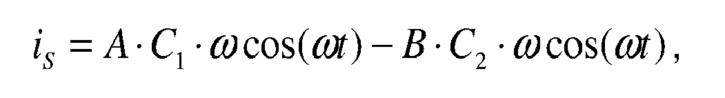
wherein: - is: is the sense current represented by the sense signal S6;
- A: is the amplitude of the first control signal S12;
- B: is the amplitude of the second control signal S14;
- C1: is the capacitance of the first capacitor 12'; and
- C2: is the capacitance of the
second capacitor 12". - It may be noted that the derivatives of the capacities have been neglected on the assumption of small and slow changes thereof in the above equation. As described above, the actual voltage value S8 is proportional to the sense signal S6. The polarity of actual voltage value S8 (i.e. the error signal) also depends on the phase relation between the periodic carrier signal S1 and the sense voltage S7 and therefore the sense current S6. This implies that, if the capacitance between the
first drive electrode 14 and the sense electrode 18 (i.e. the capacitance C1 of the equivalent capacitor 12') is greater than the capacitance between thesecond drive electrode 16 and the sense electrode 18 (i.e. the capacitance C2 of theequivalent capacitor 12"), the actual value voltage S8 is positive and vice versa. As a result, the actual value voltage S8 is a measure of the capacitive imbalance within thedifferential sense electrode 12. This imbalance is compensated by the action of theintegrator 46. In fact, by nature of the control loop, theintegrator 46 operates to drive the actual value voltage S8 (which forms the error signal) permanently towards zero. This is achieved when the output ofintegrator 46 has reached the value which makes the amplitude A of the first control signal S12 and the amplitude B of the second control signal S14 fulfil the equation:
- In this condition, the value of the sense current is represented by the sense signal S6 is zero an the circuit operates in steady state. Accordingly, the control loop comprising the
integrator 46 adapts the amplitudes A and B so as to drive the sense signal S6 towards zero. The differences in the capacitances C1 and C2, e.g. due to manufacturing tolerances, are therefore automatically compensated. In addition, any change in either capacitance C1 or C2 (e.g. due to dirt, temperature change or ageing) that is slow in time compared to the integration time constant of theintegrator 46 is automatically compensated. - If a change of imbalance between the capacitance C1 or C2 that is fast in time occurs, as is the case for a raindrop falling on the sense area above the
differential capacitor 12, the control loop is momentarily disturbed. In fact, water has a significantly higher relative permittivity (εr≈80) than air (εr≈1) such that a change in capacitance occurs in the presence of a raindrop or moisture in the sense area. The disturbance in the control loop caused by such a "wetting event" is reflected by a change in the actual value voltage S8 and appears on theoutput 48 as a positive or negative voltage, depending on whether the raindrop or moisture has fallen above the first capacitor 12' or thesecond capacitor 12". Theintegrator 46 counteracts this change by adapting the amplitude A of the first control signal S12 and the amplitude B of the second control signal S14 so as to turn back to steady state. Although dual symmetric action on both amplitudes A and B is preferred, a control loop with a single feedback path acting on one amplitude only can achieve similar results. As theintegrator 46 requires a certain time (depending on its integration time constant), the positive or negative voltage persists during a certain time on theoutput 48. As a result, the occurrence of a "wetting event", for example due to a raindrop falling on the windshield above the sense area, is indicated by a positive or negative voltage pulse on theoutput 48 of thecapacitive rain sensor 10. This pulse can then be evaluated for further processing, e.g. by a windshield wiper control device (not shown). - A number of advantages resulting from the above described sensor design may be noted. Since the sense current (signal S6) is reduced to zero after each "wetting event", the input stage of the detection circuit (i.e. the sensing amplifier 42) can have a much simpler design. It does for example not need to be linear, neither does it need to have a well defined gain nor does it need to have a large input signal range. The control loop also allows saturation of the
sensing amplifier 42 without causing malfunction. Furthermore, the control loop allows suppression of large changes in the capacitance ofcapacitors 12' and 12" which would otherwise overdrive the detection circuit and influence the measurements. Generally speaking, the control loop significantly increases the sensitivity of thecapacitive rain sensor 10. Furthermore, no reference capacitor is necessary, as only changes in capacitance are measured. Since no absolute capacitance is measured, thecapacitive rain sensor 10 also allows capacitive coupling of theelectrodes circuit 20 or thedetection circuit 40 respectively, whereby mounting of a windshield comprising thedifferential sensing electrode 12 is significantly facilitated. - Turning now to Fig.2 and Fig.3, a preferred embodiment of the
differential sensing capacitor 12 will be described. As described above, thedifferential sensing capacitor 12 comprises afirst drive electrode 14, asecond drive electrode 16 and asense electrode 18 disposed there between. As seen in Fig.2, thefirst drive electrode 14 is provided with a number offirst drive branches 140 extending away from atrunk section 142 towards thesense electrode 18. Similarly, the firstsecond drive electrode 16 is provided with a number of second drive branches 160 extending away from atrunk section 162 towards thesense electrode 18. The sense electrode inturn 18 also comprisessense branches 180 disposed on either side of a trunk section 182 thereof in such manner that thedrive branches sense branches 180. By this arrangement, the electrode area of thedifferential sensing capacitor 12 is increased without significant increase in its size. As further seen in Fig.2, twoguard electrodes 200 are disposed between thetrunk sections insensitive area 210. Theinsensitive area 210 is normally placed below the windshield area that is not cleaned by the wipers so as to make thecapacitive rain sensor 10 insensitive in this area. - Fig.3 shows how the
differential sensing capacitor 12 is preferably integrated into a windshield of an automotive vehicle for example. The windshield comprises anouter glass layer 300 defining the front face of the windshield, an intermediateplastic foil layer 302 for safety purposes and aninner glass layer 304 defining the inner face of the windshield. Theelectrodes plastic layer 302 before the latter are laminated together. As further seen in Fig.3, anadditional shield electrode 220 is disposed between theplastic layer 302 and theinner glass layer 304. Theshield electrode 220 is normally connected to ground and preferably extends over the area of thedifferential sensing capacitor 12 in the plane perpendicular to the plane of Fig.3. Theshield electrode 220 allows to make thecapacitive rain sensor 10 insensitive towards the interior side of the windshield e.g. for suppressing the response of the sensor to a touch of a finger. Additionally, theshield electrode 220 may be provided with cut out spaces for connection pads used for capacitively coupling thedifferential sensing capacitor 12 to the detection or drivingcircuit -
- capacitive rain sensor
- 10
- differential sensing capacitor
- 12
- first capacitor
- 12'
- second capacitor
- 12"
- first drive electrode
- 14
- second drive electrode
- 16
- sense electrode
- 18
- driving circuit
- 20
- carrier signal generator
- 22
- first non-inverting amplifier
- 24
- first inverting amplifier
- 26
- first mixer
- 28
- second mixer
- 30
- detection circuit
- 40
- sensing amplifier
- 42
- third mixer
- 44
- integrator
- 46
- output
- 48
- second inverting amplifier
- 50
- first adder
- 52
- second non-inverting amplifier
- 54
- second adder
- 56
- reference voltage source
- 58
- first drive branches
- 140
- trunk section
- 142, 162, 182
- second drive branches
- 160
- sense branches
- 180
- guard electrode
- 200
- insensitive area
- 210
- shield electrode
- 220
- outer glass layer
- 300
- plastic foil layer
- 302
- inner glass layer
- 304
Claims (13)
- A differential capacitive rain sensor comprising
a differential sensing capacitor having at least a first drive electrode, a second drive electrode and a sense electrode,
a driving circuit coupled to said first and said second drive electrodes for driving said first drive electrode with a first drive signal and said second drive electrode with a second drive signal, said second drive signal being substantially opposite in phase to said first drive signal, and
a detection circuit having an input coupled to said sense electrode for detecting a change in a sense signal of said sense electrode
characterized in that
said detection circuit comprises a controller using an error signal derived from said sense signal to control the amplitude of said first and/or said second drive signal so as to reduce the amplitude of said sense signal. - The capacitive rain sensor according to claim 1, wherein said error signal is available on an output of said detection circuit.
- The capacitive rain sensor according to claim 1 or 2, wherein said first and said second drive electrodes are capacitively coupled to said driving circuit and said sense electrode is capacitively coupled to said input of said detection circuit.
- The capacitive rain sensor according to any one of claims 1 to 3, wherein said controller comprises an integrator.
- The capacitive rain sensor according to any one of the preceding claims, wherein said driving circuit comprises first multiplier means providing said first drive signal by multiplying a first periodic signal by a first control signal and second multiplier means providing said second drive signal by multiplying a second periodic signal, opposite in phase to said first periodic signal, by a second control signal.
- The capacitive rain sensor according to claim 5, wherein said detection circuit comprises a reference signal source and means for subtracting the controller output signal from said reference signal so as to provide said first control signal and means for adding the controller output signal to said reference signal so as to provide said second control signal.
- The capacitive rain sensor according to claim 5 or 6, wherein said driving circuit comprises a periodic signal source connected to a non-inverting amplifier and to an inverting amplifier so as to provide said first periodic signal on the output of said non-inverting amplifier and said second periodic signal on the output of said inverting amplifier.
- The capacitive rain sensor according to any one of the preceding claims, wherein said detection circuit further comprises rectifying means for providing said error signal.
- The capacitive rain sensor according to claim 8, wherein said sense signal is a sense current flowing into/out of said sense electrode and said detection circuit further comprises a transimpedance amplifier having an input forming the input of said detection circuit and having an output connected to an input of said rectifying means.
- The capacitive rain sensor according to any of the preceding claims wherein said sense electrode is arranged between said first and said second drive electrodes, said first drive electrode comprising a plurality of first drive branches, said second drive electrode comprising a plurality of second drive branches and said sense electrode comprising a first and a second opposed set of sense branches, said first drive branches being arranged to interdigitate with said first set of sense branches and said second drive branches being arranged to interdigitate with said second set of sense branches.
- The capacitive rain sensor according to claim 10, wherein each of said first drive electrode, said second drive electrode and said sense electrode comprises an elongate trunk section, each trunk section defining a first portion to which the respective branches are connected and a second portion for coupling to said detection circuit or said driving circuit respectively.
- The capacitive rain sensor according to claim 11, further comprising two guard electrodes disposed between said second portions of said trunk sections so as to define a capacitively insensitive region.
- The capacitive rain sensor according to any of claims 10 to 12, further comprising a shield electrode extending essentially over the area of said differential sensing capacitor and disposed in a plane parallel to said differential sensing capacitor.
Priority Applications (2)
| Application Number | Priority Date | Filing Date | Title |
|---|---|---|---|
| EP05100637A EP1686026A1 (en) | 2005-01-31 | 2005-01-31 | Differential capacitive rain sensor |
| PCT/EP2006/050396 WO2006079621A1 (en) | 2005-01-31 | 2006-01-24 | Differential capacitive rain sensor |
Applications Claiming Priority (1)
| Application Number | Priority Date | Filing Date | Title |
|---|---|---|---|
| EP05100637A EP1686026A1 (en) | 2005-01-31 | 2005-01-31 | Differential capacitive rain sensor |
Publications (1)
| Publication Number | Publication Date |
|---|---|
| EP1686026A1 true EP1686026A1 (en) | 2006-08-02 |
Family
ID=34938606
Family Applications (1)
| Application Number | Title | Priority Date | Filing Date |
|---|---|---|---|
| EP05100637A Withdrawn EP1686026A1 (en) | 2005-01-31 | 2005-01-31 | Differential capacitive rain sensor |
Country Status (2)
| Country | Link |
|---|---|
| EP (1) | EP1686026A1 (en) |
| WO (1) | WO2006079621A1 (en) |
Cited By (10)
| Publication number | Priority date | Publication date | Assignee | Title |
|---|---|---|---|---|
| WO2008021809A2 (en) * | 2006-08-14 | 2008-02-21 | Ppg Industries Ohio, Inc. | Multi-layer windshield moisture detector |
| WO2008022785A2 (en) * | 2006-08-23 | 2008-02-28 | Ident Technology Ag | Arrangement for generating a signal indicative of the presence of an object within an observation region |
| WO2010012858A1 (en) * | 2008-08-01 | 2010-02-04 | Nokia Corporation | Electronic device wireless display |
| WO2014185771A3 (en) * | 2013-05-17 | 2015-04-30 | Mimos Berhad | A capacitive humidity sensor |
| WO2020048672A1 (en) * | 2018-09-03 | 2020-03-12 | Saint-Gobain Glass France | Glazing unit |
| WO2020154068A1 (en) * | 2019-01-24 | 2020-07-30 | Semiconductor Components Industries, Llc | Embedded capacitive sensor with coresponding rain detection method and rain detection system |
| US10816497B2 (en) | 2019-01-24 | 2020-10-27 | Semiconductor Components Industries, Llc | Methods and apparatus for a capacitive sensor |
| US10836354B2 (en) | 2019-01-24 | 2020-11-17 | Semiconductor Components Industries, Llc | Methods and apparatus for a capacitive sensor |
| WO2021028163A1 (en) * | 2019-08-13 | 2021-02-18 | Saint-Gobain Glass France | Composite panel with a sensor assembly on both sides |
| WO2021219507A1 (en) * | 2020-04-29 | 2021-11-04 | Robert Bosch Gmbh | Rain detection device, garden appliance having the rain detection device, and method for sensing rain drops on a surface by means of a rain detection device |
Families Citing this family (2)
| Publication number | Priority date | Publication date | Assignee | Title |
|---|---|---|---|---|
| EP4232809A1 (en) * | 2020-11-24 | 2023-08-30 | Raja Tuli | Moisture or saturation estimation of absorbent article |
| US20220249296A1 (en) * | 2021-02-11 | 2022-08-11 | Raja Singh Tuli | Moisture detection and estimation with multiple frequencies |
Citations (5)
| Publication number | Priority date | Publication date | Assignee | Title |
|---|---|---|---|---|
| US4831493A (en) * | 1987-12-28 | 1989-05-16 | Ppg Industries, Inc. | Windshield moisture sensor |
| EP0485857A2 (en) * | 1990-11-15 | 1992-05-20 | TEMIC TELEFUNKEN microelectronic GmbH | Sensor system and its application |
| US5637798A (en) * | 1994-11-03 | 1997-06-10 | Robert Bosch Gmbh | Circuit arrangement for evaluating an acceleration sensor signal |
| WO1998030922A1 (en) * | 1997-01-10 | 1998-07-16 | Netzer, Yohay | Differential windshield capacitive moisture sensors |
| DE10109873A1 (en) * | 2000-03-02 | 2001-09-13 | Denso Corp | Signal processing device |
-
2005
- 2005-01-31 EP EP05100637A patent/EP1686026A1/en not_active Withdrawn
-
2006
- 2006-01-24 WO PCT/EP2006/050396 patent/WO2006079621A1/en not_active Application Discontinuation
Patent Citations (6)
| Publication number | Priority date | Publication date | Assignee | Title |
|---|---|---|---|---|
| US4831493A (en) * | 1987-12-28 | 1989-05-16 | Ppg Industries, Inc. | Windshield moisture sensor |
| EP0485857A2 (en) * | 1990-11-15 | 1992-05-20 | TEMIC TELEFUNKEN microelectronic GmbH | Sensor system and its application |
| US5637798A (en) * | 1994-11-03 | 1997-06-10 | Robert Bosch Gmbh | Circuit arrangement for evaluating an acceleration sensor signal |
| US5801307A (en) * | 1995-07-12 | 1998-09-01 | Netzer; Yishay | Differential windshield capacitive moisture sensors |
| WO1998030922A1 (en) * | 1997-01-10 | 1998-07-16 | Netzer, Yohay | Differential windshield capacitive moisture sensors |
| DE10109873A1 (en) * | 2000-03-02 | 2001-09-13 | Denso Corp | Signal processing device |
Cited By (15)
| Publication number | Priority date | Publication date | Assignee | Title |
|---|---|---|---|---|
| WO2008021809A2 (en) * | 2006-08-14 | 2008-02-21 | Ppg Industries Ohio, Inc. | Multi-layer windshield moisture detector |
| WO2008021809A3 (en) * | 2006-08-14 | 2008-05-08 | Ppg Ind Ohio Inc | Multi-layer windshield moisture detector |
| WO2008022785A2 (en) * | 2006-08-23 | 2008-02-28 | Ident Technology Ag | Arrangement for generating a signal indicative of the presence of an object within an observation region |
| WO2008022785A3 (en) * | 2006-08-23 | 2009-03-05 | Ident Technology Ag | Arrangement for generating a signal indicative of the presence of an object within an observation region |
| WO2010012858A1 (en) * | 2008-08-01 | 2010-02-04 | Nokia Corporation | Electronic device wireless display |
| US8854296B2 (en) | 2008-08-01 | 2014-10-07 | Nokia Corporation | Electronic device wireless display |
| WO2014185771A3 (en) * | 2013-05-17 | 2015-04-30 | Mimos Berhad | A capacitive humidity sensor |
| WO2020048672A1 (en) * | 2018-09-03 | 2020-03-12 | Saint-Gobain Glass France | Glazing unit |
| CN111148667A (en) * | 2018-09-03 | 2020-05-12 | 法国圣戈班玻璃厂 | Window glass unit |
| US11803277B2 (en) | 2018-09-03 | 2023-10-31 | Saint-Gobain Glass France | Glazing unit |
| WO2020154068A1 (en) * | 2019-01-24 | 2020-07-30 | Semiconductor Components Industries, Llc | Embedded capacitive sensor with coresponding rain detection method and rain detection system |
| US10816497B2 (en) | 2019-01-24 | 2020-10-27 | Semiconductor Components Industries, Llc | Methods and apparatus for a capacitive sensor |
| US10836354B2 (en) | 2019-01-24 | 2020-11-17 | Semiconductor Components Industries, Llc | Methods and apparatus for a capacitive sensor |
| WO2021028163A1 (en) * | 2019-08-13 | 2021-02-18 | Saint-Gobain Glass France | Composite panel with a sensor assembly on both sides |
| WO2021219507A1 (en) * | 2020-04-29 | 2021-11-04 | Robert Bosch Gmbh | Rain detection device, garden appliance having the rain detection device, and method for sensing rain drops on a surface by means of a rain detection device |
Also Published As
| Publication number | Publication date |
|---|---|
| WO2006079621A1 (en) | 2006-08-03 |
Similar Documents
| Publication | Publication Date | Title |
|---|---|---|
| EP1686026A1 (en) | Differential capacitive rain sensor | |
| EP3591507B1 (en) | Capacitive detection circuit, touch detection apparatus, and terminal device | |
| KR100352794B1 (en) | Differential windshield capacitive moisture sensors | |
| US8928622B2 (en) | Demodulation method and system with low common noise and high SNR for a low-power differential sensing capacitive touch panel | |
| US8353210B2 (en) | System for measuring a physical variable | |
| US3826979A (en) | Capacitive detector device | |
| US6194903B1 (en) | Circuit for acquisition of the capacitance or capacitance change of a capacitive circuit element or component | |
| US8587329B2 (en) | Circuit arrangement for determination of a measuring capacitance | |
| US20210371000A1 (en) | Steering-wheel grip sensor and grip detection method | |
| CA2309628C (en) | Angular rate sensor | |
| US5172065A (en) | Evaluation circuit for a capacitive sensor | |
| US6486681B1 (en) | Measuring circuit for a capacitive sensor for distance measurement and/or space monitoring | |
| US9285406B2 (en) | Impedance measurement system | |
| JPH09185452A (en) | Method and device for canceling offset signal on electrostatic digitized tablet | |
| US7292021B2 (en) | Anomaly detector for vibratory angular rate sensor | |
| US10139439B2 (en) | Method of capacitive measurement between an object and an electrode plane by partial synchronous demodulation | |
| US8587553B2 (en) | Capacitance change detection circuit, touch panel and determination method | |
| EP0079955B1 (en) | Impedance measurement circuit | |
| RU2477837C2 (en) | Object detection device for mechanical transport vehicle | |
| US6184695B1 (en) | Diagnostic circuit for potentiometric sensors | |
| WO2002019524A1 (en) | Controller for a capacitive sensor | |
| JP3772044B2 (en) | Capacitance type detection device | |
| WO1998007051A1 (en) | Phase shift detection and measurement circuit for capacitive sensor | |
| EP0816805B1 (en) | Sensor circuit | |
| US20120285245A1 (en) | Sensing apparatus |
Legal Events
| Date | Code | Title | Description |
|---|---|---|---|
| PUAI | Public reference made under article 153(3) epc to a published international application that has entered the european phase |
Free format text: ORIGINAL CODE: 0009012 |
|
| AK | Designated contracting states |
Kind code of ref document: A1 Designated state(s): AT BE BG CH CY CZ DE DK EE ES FI FR GB GR HU IE IS IT LI LT LU MC NL PL PT RO SE SI SK TR |
|
| AX | Request for extension of the european patent |
Extension state: AL BA HR LV MK YU |
|
| AKX | Designation fees paid | ||
| REG | Reference to a national code |
Ref country code: DE Ref legal event code: 8566 |
|
| STAA | Information on the status of an ep patent application or granted ep patent |
Free format text: STATUS: THE APPLICATION IS DEEMED TO BE WITHDRAWN |
|
| 18D | Application deemed to be withdrawn |
Effective date: 20070203 |