EP1679290A1 - Chuck plate assembly with cooling means - Google Patents
Chuck plate assembly with cooling means Download PDFInfo
- Publication number
- EP1679290A1 EP1679290A1 EP06100099A EP06100099A EP1679290A1 EP 1679290 A1 EP1679290 A1 EP 1679290A1 EP 06100099 A EP06100099 A EP 06100099A EP 06100099 A EP06100099 A EP 06100099A EP 1679290 A1 EP1679290 A1 EP 1679290A1
- Authority
- EP
- European Patent Office
- Prior art keywords
- shadow mask
- glass substrate
- chuck plate
- cooling
- plate assembly
- Prior art date
- Legal status (The legal status is an assumption and is not a legal conclusion. Google has not performed a legal analysis and makes no representation as to the accuracy of the status listed.)
- Granted
Links
- 238000001816 cooling Methods 0.000 title claims abstract description 63
- 239000000758 substrate Substances 0.000 claims abstract description 66
- 239000011521 glass Substances 0.000 claims abstract description 59
- 238000000151 deposition Methods 0.000 claims abstract description 37
- 239000011368 organic material Substances 0.000 claims abstract description 11
- 239000003507 refrigerant Substances 0.000 claims description 42
- XAGFODPZIPBFFR-UHFFFAOYSA-N aluminium Chemical compound [Al] XAGFODPZIPBFFR-UHFFFAOYSA-N 0.000 claims description 3
- 229910052782 aluminium Inorganic materials 0.000 claims description 3
- 230000008021 deposition Effects 0.000 description 33
- 238000005137 deposition process Methods 0.000 description 11
- 238000000034 method Methods 0.000 description 7
- 239000010408 film Substances 0.000 description 6
- 239000000463 material Substances 0.000 description 6
- 230000000694 effects Effects 0.000 description 5
- 230000000630 rising effect Effects 0.000 description 3
- 239000003086 colorant Substances 0.000 description 2
- 230000007423 decrease Effects 0.000 description 2
- 239000004065 semiconductor Substances 0.000 description 2
- 239000010409 thin film Substances 0.000 description 2
- 230000015556 catabolic process Effects 0.000 description 1
- 230000002950 deficient Effects 0.000 description 1
- 238000006731 degradation reaction Methods 0.000 description 1
- 238000003618 dip coating Methods 0.000 description 1
- 238000002845 discoloration Methods 0.000 description 1
- 230000002708 enhancing effect Effects 0.000 description 1
- 238000001704 evaporation Methods 0.000 description 1
- 238000007641 inkjet printing Methods 0.000 description 1
- 229920000642 polymer Polymers 0.000 description 1
- 239000002904 solvent Substances 0.000 description 1
- 238000004528 spin coating Methods 0.000 description 1
Images


Classifications
-
- C—CHEMISTRY; METALLURGY
- C03—GLASS; MINERAL OR SLAG WOOL
- C03C—CHEMICAL COMPOSITION OF GLASSES, GLAZES OR VITREOUS ENAMELS; SURFACE TREATMENT OF GLASS; SURFACE TREATMENT OF FIBRES OR FILAMENTS MADE FROM GLASS, MINERALS OR SLAGS; JOINING GLASS TO GLASS OR OTHER MATERIALS
- C03C17/00—Surface treatment of glass, not in the form of fibres or filaments, by coating
- C03C17/28—Surface treatment of glass, not in the form of fibres or filaments, by coating with organic material
-
- C—CHEMISTRY; METALLURGY
- C03—GLASS; MINERAL OR SLAG WOOL
- C03C—CHEMICAL COMPOSITION OF GLASSES, GLAZES OR VITREOUS ENAMELS; SURFACE TREATMENT OF GLASS; SURFACE TREATMENT OF FIBRES OR FILAMENTS MADE FROM GLASS, MINERALS OR SLAGS; JOINING GLASS TO GLASS OR OTHER MATERIALS
- C03C17/00—Surface treatment of glass, not in the form of fibres or filaments, by coating
- C03C17/001—General methods for coating; Devices therefor
- C03C17/002—General methods for coating; Devices therefor for flat glass, e.g. float glass
-
- C—CHEMISTRY; METALLURGY
- C23—COATING METALLIC MATERIAL; COATING MATERIAL WITH METALLIC MATERIAL; CHEMICAL SURFACE TREATMENT; DIFFUSION TREATMENT OF METALLIC MATERIAL; COATING BY VACUUM EVAPORATION, BY SPUTTERING, BY ION IMPLANTATION OR BY CHEMICAL VAPOUR DEPOSITION, IN GENERAL; INHIBITING CORROSION OF METALLIC MATERIAL OR INCRUSTATION IN GENERAL
- C23C—COATING METALLIC MATERIAL; COATING MATERIAL WITH METALLIC MATERIAL; SURFACE TREATMENT OF METALLIC MATERIAL BY DIFFUSION INTO THE SURFACE, BY CHEMICAL CONVERSION OR SUBSTITUTION; COATING BY VACUUM EVAPORATION, BY SPUTTERING, BY ION IMPLANTATION OR BY CHEMICAL VAPOUR DEPOSITION, IN GENERAL
- C23C14/00—Coating by vacuum evaporation, by sputtering or by ion implantation of the coating forming material
- C23C14/04—Coating on selected surface areas, e.g. using masks
- C23C14/042—Coating on selected surface areas, e.g. using masks using masks
-
- C—CHEMISTRY; METALLURGY
- C23—COATING METALLIC MATERIAL; COATING MATERIAL WITH METALLIC MATERIAL; CHEMICAL SURFACE TREATMENT; DIFFUSION TREATMENT OF METALLIC MATERIAL; COATING BY VACUUM EVAPORATION, BY SPUTTERING, BY ION IMPLANTATION OR BY CHEMICAL VAPOUR DEPOSITION, IN GENERAL; INHIBITING CORROSION OF METALLIC MATERIAL OR INCRUSTATION IN GENERAL
- C23C—COATING METALLIC MATERIAL; COATING MATERIAL WITH METALLIC MATERIAL; SURFACE TREATMENT OF METALLIC MATERIAL BY DIFFUSION INTO THE SURFACE, BY CHEMICAL CONVERSION OR SUBSTITUTION; COATING BY VACUUM EVAPORATION, BY SPUTTERING, BY ION IMPLANTATION OR BY CHEMICAL VAPOUR DEPOSITION, IN GENERAL
- C23C14/00—Coating by vacuum evaporation, by sputtering or by ion implantation of the coating forming material
- C23C14/22—Coating by vacuum evaporation, by sputtering or by ion implantation of the coating forming material characterised by the process of coating
- C23C14/54—Controlling or regulating the coating process
- C23C14/541—Heating or cooling of the substrates
Definitions
- the present invention relates to a device that prevents thermal deformation of a glass substrate needed for an organic semiconductor device and more particularly, to a shadow mask frame having heat-radiating and cooling functions, and a chuck plate used in attaching a glass plate to a shadow mask and having a cooling means, in which a refrigerant is circulated in the chuck plate, thereby preventing the temperature from increasing in the glass plate due to radiant heat from a deposition source under a vacuum atmosphere or conductive heat caused by contact with a shadow mask, thereby improving precision of the alignment between the glass substrate and the shadow mask.
- an organic thin film of an organic semiconductor device such as an organic light emitting diode, for example, is formed by evaporating a low molecular organic material under a vacuum atmosphere, or by using a spin coating method, a dip coating method, a doctor blade, or an inkjet printing method after dissolving a polymer organic material in a solvent.
- a shadow mask having a predetermined pattern is needed for depositing an organic material at a proper layer.
- the shadow mask is fixed to a shadow mask frame.
- a glass substrate is provided it is aligned with and attached to the shadow mask, and then a film growth process is performed.
- a dotted-type or linear-type organic material deposition source is used to deposit the low molecular organic material on the glass substrate according to a predetermined pattern.
- FIG. 1 schematically illustrates a typical deposition process using a vertical type deposition source, which directs a low molecular organic material towards a mask having a predetermined pattern when an organic light emitting display is fabricated, for example.
- a shadow mask 20 having a predetermined pattern is mounted to a shadow mask frame 10, and then a glass substrate 30 is aligned by a chuck plate 40 and a rubber magnet 50.
- a deposition material from a vertical type deposition source 70 is deposited on the glass substrate 30 via the shadow mask 20.
- the deposition process is performed in a vacuum atmosphere.
- radiant heat R is transferred from the deposition source to the shadow mask and, thus, increasing its temperature.
- the temperature of the shadow mask rises, it thermally expands and thereby decreases the precision of a pattern position of an organic light emitting diode. This reduces the precision of the pattern position for representing red R, green G and blue B colors and results in the mixing of R, G and B colors, which is known as "discoloration defective.”
- the glass substrate is affected by not only the radiant heat from the deposition source but also conductive heat due to direct contact with the shadow mask, so that the temperature of the glass substrate continuously rises.
- the glass substrate it is difficult to radiate away the heat, which accumulates via successive deposition processes. Therefore, the difference in thermal deformation between the glass substrate and the shadow mask becomes larger when only the shadow mask frame is cooled.
- a shadow mask frame assembly which has a heat-radiating function to fundamentally prevent a radiant heat transfer from a deposition source, and a cooling function to prevent the heat from being accumulated in a shadow mask, thereby suppressing thermal expansion of the shadow mask. This improves the precision of a pattern position of an organic light emitting diode.
- the chuck plate assembly for depositing an organic material on a glass substrate according to the invention comprises:
- the temperature of the substrate is optimized so that an alignment error due to thermal deformation is minimized.
- a first embodiment of the invention provides a chuck plate assembly, wherein the cooling element is a cooling plate aligned and attached to the shadow mask and/or the shadow mask frame.
- the cooling plate is preferable mounted with an inner portion on at least a part of the shadow mask and with an exposure portion on at least a part of the shadow mask frame, wherein the inner portion extending from the exposure portion towards the shadow mask is having a tapered profile.
- a second embodiment of the invention provides a chuck plate assembly further comprising a chuck plate aligned and attached with its front surface to the back side of glass substrate, wherein
- the chuck plate is made of aluminum.
- the chuck plate assembly preferable further comprising a temperature adjuster to adjust a temperature of the refrigerant circulating through the refrigerant circulating duct based on a temperature of the shadow mask.
- An embodiment of the invention provides a chuck plate assembly that includes a shadow mask formed with a predetermined pattern; a shadow mask frame to which the shadow mask is attached; and a cooling plate mounted on a portion of the shadow mask frame exposed to a deposition source.
- a chuck plate assembly that includes a shadow mask formed with a predetermined pattern; a shadow mask frame for holding the shadow mask; a substrate aligned with the shadow mask and to which a deposition material from a deposition source is deposited; and a chuck plate attaching the substrate to the shadow mask by having a front surface facing the deposition source closely attached to a back surface of the substrate facing away from the deposition source, wherein the chuck plate includes a refrigerant circulating duct through which a refrigerant circulates.
- a chuck plate assembly further comprises an external cooling plate mounted on a back surface of the chuck plate opposite surface attached to the substrate.
- the external cooling plate rather than the chuck plate, includes the refrigerant circulating duct through which the refrigerant circulates.
- a shadow mask 120 having a predetermined pattern is mounted to a shadow mask frame 110.
- a distance from a deposition source 170 to the shadow mask 120 and a substrate 130 can be approximately 300 mm or more, and the deposition source 170 has a nozzle temperature of about 200 °C . Therefore, radiant heat R from the deposition source 170 causes the shadow mask 120 to thermally expand. At this time, the thermal expansion of the shadow mask 120 is directly affected by the temperature of the shadow mask frame 110.
- a heat radiating method or a cooling method can be used to suppress the thermal expansion of the shadow mask 120.
- the heat-radiating method intercepts the radiant heat R from the deposition source 170.
- the cooling method prevents the heat from being accumulated in the shadow mask 120.
- the glass substrate 130 is having a back and a front side.
- the shadow mask with the predetermined pattern is being aligned and attached to the front side of the glass substrate 130.
- the shadow mask frame 110 is being aligned and attached to the shadow mask.
- the chuck plate assembly for deposition of an organic material on the front side of the glass substrate 130 further comprises a cooling element being assembled on the back side and/or the front side of the glass substrate 130.
- a cooling plate 60 can be mounted to a portion of the shadow mask frame 110 facing the deposition source 170, thereby performing both the heat-radiating and cooling methods.
- the cooling plate 60 intercepts the radiant heat R from the shadow mask frame 110 and removes the heat accumulated in the shadow mask frame 110.
- the cooling element is the cooling plate 60 which is attached to the shadow mask 120 and/or the shadow mask frame 110.
- the cooling plate 60 which is mounted to the mask frame 110 that faces the vertical type deposition source 170 and is exposed to the radiant heat, prevents the temperature of the shadow mask frame 110 from rising. This prevents deformation of the shadow mask 120 due to the thermal expansion, thereby enhancing precision in a pattern position.
- cooling plate 60 may obstruct a deposition material from the vertical type deposition source 170 and thus decrease a film growth region of the substrate.
- the cooling plate 60 may include an exposure portion 60a facing the deposition source 170, and an inner portion 60b facing the film growth region as shown in FIG. 3 and FIG. 4.
- the inner portion 60b of the cooling plate 60 is tapered. Because the inner portion 60b of the cooling plate 60 has a tapered profile, the film growth region of the substrate is secured regardless of variations in the vertical position of the deposition source 170, thereby preserving the film growth region.
- the cooling plate 60 surrounds the mask frame 110 entirely so as to heighten the heat-radiating and cooling effects of the mask frame 110.
- cooling plate 60 according to an embodiment of the present invention can be made of various heat-radiating materials as known to those persons of ordinary skill in the art.
- the glass substrate 130 and the shadow mask 120 are aligned and attached by a chuck plate 140 and a rubber magnet 150, and the cooling plate 60 having the tapered profile is mounted to the shadow mask frame 110.
- the cooling plate 60 intercepts the radiant heat from the deposition source 170 and prevents the heat from being accumulated in the shadow mask 120.
- the cooling plate 60 does not completely prevent the temperature of the glass substrate 130 from being affected by the radiant heat transferred from the deposition source 170 and the conductive heat due to direct contact with the shadow mask 120. Therefore, in the case where only the shadow mask frame 110 is cooled, the difference in thermal deformation between the glass substrate 130 and the shadow mask 120 widens.
- the present invention can provide a chuck plate 140 for cooling a glass substrate 130 according to another embodiment of the present invention, as shown in FIG. 6, for example.
- a chuck plate assembly may include a shadow mask 120 having a predetermined pattern; a shadow mask frame 110 to hold the shadow mask 120; a cooling plate 60 placed in a part of the shadow mask frame 110 exposed to a deposition source that prevents thermal deformation in the shadow mask frame 110; and a chuck plate 140 making a glass substrate 130 be aligned with and attached to the shadow mask 120.
- the chuck plate 140 can be formed with a refrigerant circulating duct 41. Deposition materials are deposited from the deposition source onto the glass substrate 130, forming a predetermined pattern.
- the chuck plate 140 supports the glass substrate 130 from its back side and makes the glass substrate 130 be aligned with and attached to the shadow mask 120.
- the refrigerant circulating duct 41 is directly formed inside the chuck plate 140 so that a refrigerant is circulated through the refrigerant circulating duct 41, thereby cooling the glass substrate 130.
- the chuck plate 140 can be made of aluminum and attached to cover a back side of the glass substrate 130 in the deposition process, thereby having a good cooling effect on the glass substrate 130.
- the refrigerant circulating duct 41 can be formed inside the chuck plate 40 by various methods. The longer the refrigerant circulating duct 41 is, the better the cooling effect is given to the glass substrate 130. Thus, the refrigerant circulating duct 41 is preferably lengthened to enhance this cooling effect.
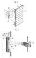
- the refrigerant circulating duct 41 can be designed in consideration of the size of the chuck plate 140 and the desired cooling effect, for example. As shown in FIG. 6 and FIG. 7, the refrigerant circulating duct 41 has an inlet 42 placed at a first edge of the chuck plate 140, and an outlet 43 placed at a second edge of the chuck plate 140. Alternatively, the inlet and the outlet of the refrigerant circulating duct 41 may be placed at the same edge of the chuck plate.
- a temperature adjuster (not shown) may be provided to adjust the temperature of the refrigerant circulating through the refrigerant circulating duct 41.
- the temperature of the refrigerant circulating through the refrigerant circulating duct 41 can be optimized in consideration of the temperature of the glass substrate 130 and the shadow mask 120.
- a thermometer (not shown) may be provided to measure the temperature of the shadow mask 120.
- the cooling plate 60 mounted to the shadow mask frame 110 suppresses the temperature of the shadow mask frame 110 from rising, and thus prevents the shadow mask 120 from thermal deformation due to thermal expansion of the shadow mask 120.
- the refrigerant circulates through the refrigerant circulating duct 41 formed inside the chuck plate 140 employed for making the shadow mask 120 be aligned with and attached to the glass substrate 130, so that the glass substrate 130 is cooled, thereby minimizing difference in the thermal deformation between the glass substrate 130 and the shadow mask 120.
- the temperature difference between the glass substrate 130 and the shadow mask 120 is minimized.
- an alignment error due to the thermal expansion of the glass substrate 130 and the shadow mask 120 is minimized, thereby improving precision in the alignment between the glass substrate 130 and the shadow mask 120.
- a chuck plate assembly may further include an external cooling plate 45 mounted on the outside of the chuck plate 140 formed with a refrigerant circulating duct 46.
- refrigerant circulating duct 41 The same considerations that apply to refrigerant circulating duct 41, described above, also apply to refrigerant circulating duct 46.
- the refrigerant circulating duct 46 has an inlet 47 placed at a first edge of the external cooling plate 45, and an outlet 48 placed at a second edge of the external cooling plate 45.
- the inlet and the outlet of the refrigerant circulating duct may be placed at the same edge of the cooling plate 45.
- a temperature adjuster (not shown) and a thermometer (not shown) may also be used to optimize the temperature of the glass substrate 130 and the shadow mask 120.
- the refrigerant circulates through the refrigerant circulating duct 46 formed inside the external cooling plate 45 that is mounted to the outside of the chuck plate 140 so that the glass substrate 130 is indirectly cooled, thereby minimizing difference in the thermal deformation between the glass substrate 130 and the shadow mask 120.
- the external cooling plate 45 may be made of various heat-radiating materials as known to persons having ordinary skill in the art.
- cooling plate 60 when the cooling plate is mounted to a portion of the shadow mask frame facing the deposition source, not only the radiant heat from the deposition source is intercepted by cooling plate 60, but also the temperature of the shadow mask itself is prevented from rising, so that deformation of the shadow mask due to thermal expansion is prevented, thereby also preventing degradation of the pattern position precision caused by the thermal expansion of the shadow mask 120.
Abstract
Description
- The present invention relates to a device that prevents thermal deformation of a glass substrate needed for an organic semiconductor device and more particularly, to a shadow mask frame having heat-radiating and cooling functions, and a chuck plate used in attaching a glass plate to a shadow mask and having a cooling means, in which a refrigerant is circulated in the chuck plate, thereby preventing the temperature from increasing in the glass plate due to radiant heat from a deposition source under a vacuum atmosphere or conductive heat caused by contact with a shadow mask, thereby improving precision of the alignment between the glass substrate and the shadow mask.
- Generally, an organic thin film of an organic semiconductor device such as an organic light emitting diode, for example, is formed by evaporating a low molecular organic material under a vacuum atmosphere, or by using a spin coating method, a dip coating method, a doctor blade, or an inkjet printing method after dissolving a polymer organic material in a solvent.
- In particular, where the thin film including the low molecular organic material is fabricated in the vacuum atmosphere, a shadow mask having a predetermined pattern is needed for depositing an organic material at a proper layer. The shadow mask is fixed to a shadow mask frame. When a glass substrate is provided it is aligned with and attached to the shadow mask, and then a film growth process is performed. During the film growth process, a dotted-type or linear-type organic material deposition source is used to deposit the low molecular organic material on the glass substrate according to a predetermined pattern.
- FIG. 1 schematically illustrates a typical deposition process using a vertical type deposition source, which directs a low molecular organic material towards a mask having a predetermined pattern when an organic light emitting display is fabricated, for example. In the deposition process, a
shadow mask 20 having a predetermined pattern is mounted to ashadow mask frame 10, and then aglass substrate 30 is aligned by achuck plate 40 and arubber magnet 50. Then, a deposition material from a verticaltype deposition source 70 is deposited on theglass substrate 30 via theshadow mask 20. Here, the deposition process is performed in a vacuum atmosphere. - In the above described deposition process, radiant heat R is transferred from the deposition source to the shadow mask and, thus, increasing its temperature. As the temperature of the shadow mask rises, it thermally expands and thereby decreases the precision of a pattern position of an organic light emitting diode. This reduces the precision of the pattern position for representing red R, green G and blue B colors and results in the mixing of R, G and B colors, which is known as "discoloration defective."
- Further, the glass substrate is affected by not only the radiant heat from the deposition source but also conductive heat due to direct contact with the shadow mask, so that the temperature of the glass substrate continuously rises. Particularly, in the case of the glass substrate, it is difficult to radiate away the heat, which accumulates via successive deposition processes. Therefore, the difference in thermal deformation between the glass substrate and the shadow mask becomes larger when only the shadow mask frame is cooled.
- Accordingly, it is an aspect of the present invention to provide a shadow mask frame assembly which has a heat-radiating function to fundamentally prevent a radiant heat transfer from a deposition source, and a cooling function to prevent the heat from being accumulated in a shadow mask, thereby suppressing thermal expansion of the shadow mask. This improves the precision of a pattern position of an organic light emitting diode.
- The underlying problem is solved by the chuck plate assembly according to claim 1. The chuck plate assembly for depositing an organic material on a glass substrate according to the invention comprises:
- the glass substrate having a back side and a front side;
- a shadow mask formed with a predetermined pattern, and being aligned and attached to the front side of the glass substrate;
- a shadow mask frame being aligned and attached to the shadow mask; and
- a cooling element being assembled on the back side and/or the front side of the glass substrate.
- The temperature of the substrate is optimized so that an alignment error due to thermal deformation is minimized.
- A first embodiment of the invention provides a chuck plate assembly, wherein the cooling element is a cooling plate aligned and attached to the shadow mask and/or the shadow mask frame. The cooling plate is preferable mounted with an inner portion on at least a part of the shadow mask and with an exposure portion on at least a part of the shadow mask frame, wherein the inner portion extending from the exposure portion towards the shadow mask is having a tapered profile.
- A second embodiment of the invention provides a chuck plate assembly further comprising a chuck plate aligned and attached with its front surface to the back side of glass substrate, wherein
- (i) the chuck plate includes a refrigerant circulating duct as the cooling element through which a refrigerant circulates and/or
- (ii) an external cooling plate is mounted on a back surface of the chuck plate opposite the front surface closely attached to the glass substrate, wherein the external cooling plate includes a refrigerant circulating duct as cooling element through which a refrigerant circulates.
- Preferable the chuck plate is made of aluminum. The chuck plate assembly preferable further comprising a temperature adjuster to adjust a temperature of the refrigerant circulating through the refrigerant circulating duct based on a temperature of the shadow mask.
- An embodiment of the invention provides a chuck plate assembly that includes a shadow mask formed with a predetermined pattern; a shadow mask frame to which the shadow mask is attached; and a cooling plate mounted on a portion of the shadow mask frame exposed to a deposition source.
- Another embodiment of the invention provides a chuck plate assembly that includes a shadow mask formed with a predetermined pattern; a shadow mask frame for holding the shadow mask; a substrate aligned with the shadow mask and to which a deposition material from a deposition source is deposited; and a chuck plate attaching the substrate to the shadow mask by having a front surface facing the deposition source closely attached to a back surface of the substrate facing away from the deposition source, wherein the chuck plate includes a refrigerant circulating duct through which a refrigerant circulates.
- In yet another embodiment of the invention, a chuck plate assembly further comprises an external cooling plate mounted on a back surface of the chuck plate opposite surface attached to the substrate. In this embodiment, the external cooling plate, rather than the chuck plate, includes the refrigerant circulating duct through which the refrigerant circulates.
- These and other aspects of the invention will become apparent and more readily appreciated from the following description of the preferred embodiments, taken in conjunction with the accompanying drawings.
- FIG. 1 is a schematic view for illustrating a general deposition process using a vertical type deposition source.
- FIG. 2 is a schematic view for illustrating a deposition process with a mask frame according to an embodiment of the present invention.
- FIG. 3 is an enlarged view of "A" in FIG. 2.
- FIG. 4 is a schematic view for illustrating a cooling plate mounted to the mask frame according to an embodiment of the present invention, wherein the cooling plate is capable of preventing a shadow phenomenon.
- FIG. 5 is a detailed and enlarged sectional view for illustrating alignment and attachment between a glass substrate and a shadow mask according to an embodiment of the present invention.
- FIG. 6 shows a schematic plan view and a schematic side view of a chuck plate for cooling a glass substrate according to another embodiment of the present invention.
- FIG. 7 is a perspective view of the chuck plate according to another embodiment of the present invention.
- FIG. 8 is a schematic view of the deposition process using the chuck plate according to another embodiment of the present invention.
- FIG. 9 shows a schematic plan view and a schematic side view of a chuck plate for cooling a glass substrate according to yet another embodiment of the present invention.
- FIG. 10 is a perspective view of the chuck plate according to yet another embodiment of the present invention.
- FIG. 11 is a detailed and enlarged sectional view for illustrating alignment and attachment between a glass substrate and a shadow mask according to yet another embodiment of the present invention.
- FIG. 12 is a schematic view of the deposition process using the chuck plate according to yet another embodiment of the present invention.
- Hereinafter, preferable embodiments according to the present invention will be described with reference to the accompanying drawings, wherein embodiments of the present invention are provided to be readily understood by those skilled in the art.
- As shown in FIG. 2, a
shadow mask 120 having a predetermined pattern is mounted to ashadow mask frame 110. In a general deposition process, a distance from adeposition source 170 to theshadow mask 120 and asubstrate 130 can be approximately 300 mm or more, and thedeposition source 170 has a nozzle temperature of about 200 °C . Therefore, radiant heat R from thedeposition source 170 causes theshadow mask 120 to thermally expand. At this time, the thermal expansion of theshadow mask 120 is directly affected by the temperature of theshadow mask frame 110. - A heat radiating method or a cooling method can be used to suppress the thermal expansion of the
shadow mask 120. The heat-radiating method intercepts the radiant heat R from thedeposition source 170. The cooling method prevents the heat from being accumulated in theshadow mask 120. - The
glass substrate 130 is having a back and a front side. The shadow mask with the predetermined pattern is being aligned and attached to the front side of theglass substrate 130. Theshadow mask frame 110 is being aligned and attached to the shadow mask. The chuck plate assembly for deposition of an organic material on the front side of theglass substrate 130 further comprises a cooling element being assembled on the back side and/or the front side of theglass substrate 130. - According to an embodiment of the present invention, a cooling
plate 60 can be mounted to a portion of theshadow mask frame 110 facing thedeposition source 170, thereby performing both the heat-radiating and cooling methods. The coolingplate 60 intercepts the radiant heat R from theshadow mask frame 110 and removes the heat accumulated in theshadow mask frame 110. In other words, the cooling element is the coolingplate 60 which is attached to theshadow mask 120 and/or theshadow mask frame 110. - The cooling
plate 60, which is mounted to themask frame 110 that faces the verticaltype deposition source 170 and is exposed to the radiant heat, prevents the temperature of theshadow mask frame 110 from rising. This prevents deformation of theshadow mask 120 due to the thermal expansion, thereby enhancing precision in a pattern position. - In the meantime, a problem may arise wherein the cooling
plate 60 may obstruct a deposition material from the verticaltype deposition source 170 and thus decrease a film growth region of the substrate. - To solve this problem, the cooling
plate 60 may include anexposure portion 60a facing thedeposition source 170, and aninner portion 60b facing the film growth region as shown in FIG. 3 and FIG. 4. Here, theinner portion 60b of the coolingplate 60 is tapered. Because theinner portion 60b of the coolingplate 60 has a tapered profile, the film growth region of the substrate is secured regardless of variations in the vertical position of thedeposition source 170, thereby preserving the film growth region. - Preferably, the cooling
plate 60 surrounds themask frame 110 entirely so as to heighten the heat-radiating and cooling effects of themask frame 110. - Further, the cooling
plate 60 according to an embodiment of the present invention can be made of various heat-radiating materials as known to those persons of ordinary skill in the art. - Looking at FIG. 5, the
glass substrate 130 and theshadow mask 120 are aligned and attached by achuck plate 140 and arubber magnet 150, and the coolingplate 60 having the tapered profile is mounted to theshadow mask frame 110. The coolingplate 60 intercepts the radiant heat from thedeposition source 170 and prevents the heat from being accumulated in theshadow mask 120. However, the coolingplate 60 does not completely prevent the temperature of theglass substrate 130 from being affected by the radiant heat transferred from thedeposition source 170 and the conductive heat due to direct contact with theshadow mask 120. Therefore, in the case where only theshadow mask frame 110 is cooled, the difference in thermal deformation between theglass substrate 130 and theshadow mask 120 widens. - To solve this problem, the present invention can provide a
chuck plate 140 for cooling aglass substrate 130 according to another embodiment of the present invention, as shown in FIG. 6, for example. - Referring to FIG. 6 and FIG. 7, a chuck plate assembly may include a
shadow mask 120 having a predetermined pattern; ashadow mask frame 110 to hold theshadow mask 120; acooling plate 60 placed in a part of theshadow mask frame 110 exposed to a deposition source that prevents thermal deformation in theshadow mask frame 110; and achuck plate 140 making aglass substrate 130 be aligned with and attached to theshadow mask 120. Thechuck plate 140 can be formed with arefrigerant circulating duct 41. Deposition materials are deposited from the deposition source onto theglass substrate 130, forming a predetermined pattern. - The
chuck plate 140 supports theglass substrate 130 from its back side and makes theglass substrate 130 be aligned with and attached to theshadow mask 120. Therefrigerant circulating duct 41 is directly formed inside thechuck plate 140 so that a refrigerant is circulated through therefrigerant circulating duct 41, thereby cooling theglass substrate 130. - The
chuck plate 140 can be made of aluminum and attached to cover a back side of theglass substrate 130 in the deposition process, thereby having a good cooling effect on theglass substrate 130. - The
refrigerant circulating duct 41 can be formed inside thechuck plate 40 by various methods. The longer therefrigerant circulating duct 41 is, the better the cooling effect is given to theglass substrate 130. Thus, therefrigerant circulating duct 41 is preferably lengthened to enhance this cooling effect. - Further, the
refrigerant circulating duct 41 can be designed in consideration of the size of thechuck plate 140 and the desired cooling effect, for example. As shown in FIG. 6 and FIG. 7, therefrigerant circulating duct 41 has aninlet 42 placed at a first edge of thechuck plate 140, and anoutlet 43 placed at a second edge of thechuck plate 140. Alternatively, the inlet and the outlet of the refrigerant circulatingduct 41 may be placed at the same edge of the chuck plate. - Additionally, a temperature adjuster (not shown) may be provided to adjust the temperature of the refrigerant circulating through the
refrigerant circulating duct 41. In this case, the temperature of the refrigerant circulating through therefrigerant circulating duct 41 can be optimized in consideration of the temperature of theglass substrate 130 and theshadow mask 120. Further, a thermometer (not shown) may be provided to measure the temperature of theshadow mask 120. - Looking at FIG. 8, when radiant heat R is transferred from the
deposition source 170 to theshadow mask 120 and theglass substrate 130, the coolingplate 60 mounted to theshadow mask frame 110 suppresses the temperature of theshadow mask frame 110 from rising, and thus prevents theshadow mask 120 from thermal deformation due to thermal expansion of theshadow mask 120. - Further, the refrigerant circulates through the
refrigerant circulating duct 41 formed inside thechuck plate 140 employed for making theshadow mask 120 be aligned with and attached to theglass substrate 130, so that theglass substrate 130 is cooled, thereby minimizing difference in the thermal deformation between theglass substrate 130 and theshadow mask 120. - As the temperature of the refrigerant circulating through the
refrigerant circulating duct 41 is optimized in consideration of the temperature of theshadow mask 120, the temperature difference between theglass substrate 130 and theshadow mask 120 is minimized. Thus, an alignment error due to the thermal expansion of theglass substrate 130 and theshadow mask 120 is minimized, thereby improving precision in the alignment between theglass substrate 130 and theshadow mask 120. - As shown in FIG. 9 through FIG. 11, a chuck plate assembly according to yet another embodiment of the present invention may further include an
external cooling plate 45 mounted on the outside of thechuck plate 140 formed with arefrigerant circulating duct 46. - The same considerations that apply to refrigerant circulating
duct 41, described above, also apply to refrigerant circulatingduct 46. - The
refrigerant circulating duct 46 has aninlet 47 placed at a first edge of theexternal cooling plate 45, and anoutlet 48 placed at a second edge of theexternal cooling plate 45. Alternatively, the inlet and the outlet of the refrigerant circulating duct may be placed at the same edge of the coolingplate 45. A temperature adjuster (not shown) and a thermometer (not shown) may also be used to optimize the temperature of theglass substrate 130 and theshadow mask 120. - Referring to FIG. 12, the refrigerant circulates through the
refrigerant circulating duct 46 formed inside theexternal cooling plate 45 that is mounted to the outside of thechuck plate 140 so that theglass substrate 130 is indirectly cooled, thereby minimizing difference in the thermal deformation between theglass substrate 130 and theshadow mask 120. Here, theexternal cooling plate 45, according to yet another embodiment of the present invention, may be made of various heat-radiating materials as known to persons having ordinary skill in the art. - As described above, when the cooling plate is mounted to a portion of the shadow mask frame facing the deposition source, not only the radiant heat from the deposition source is intercepted by cooling
plate 60, but also the temperature of the shadow mask itself is prevented from rising, so that deformation of the shadow mask due to thermal expansion is prevented, thereby also preventing degradation of the pattern position precision caused by the thermal expansion of theshadow mask 120.
Claims (6)
- A chuck plate assembly for depositing an organic material on a glass substrate (130), comprising:the glass substrate (130) having a back side and a front side;a shadow mask (120) formed with a predetermined pattern, and being aligned and attached to the front side of the glass substrate (130);a shadow mask frame (110) being aligned and attached to the shadow mask (120); anda cooling element being assembled on the back side and/or the front side of the glass substrate (130).
- The chuck plate assembly of claim 1, wherein the cooling element is a cooling plate (60) aligned and attached to the shadow mask (120) and/or the shadow mask frame (110).
- The chuck plate assembly of claim 2, wherein the cooling plate (60) is mounted with an inner portion (60a) on at least a part of the shadow mask (120) and with an exposure portion (60b) on at least a part of the shadow mask frame (110), wherein the inner portion (60a) extending from the exposure portion (60b) towards the shadow mask (120) is having a tapered profile.
- The chuck plate assembly according to any of the claims 1 to 3, the chuck plate assembly further comprising a chuck plate (140) aligned and attached with its front surface to the back side of glass substrate (130), wherein(i) the chuck plate (140) includes a refrigerant circulating duct (41) as the cooling element through which a refrigerant circulates and/or(ii) an external cooling plate (45) is mounted on a back surface of the chuck plate (140) opposite the front surface closely attached to the glass substrate (130), wherein the external cooling plate (45) includes a refrigerant circulating duct (46) as cooling element through which a refrigerant circulates.
- The chuck plate assembly of claim 4, wherein the chuck plate (140) is made of aluminum.
- The chuck plate assembly of claim 4, further comprising a temperature adjuster to adjust a temperature of the refrigerant circulating through the refrigerant circulating duct (41, 46) based on a temperature of the shadow mask (120).
Applications Claiming Priority (2)
| Application Number | Priority Date | Filing Date | Title |
|---|---|---|---|
| KR1020050000966A KR100688815B1 (en) | 2005-01-05 | 2005-01-05 | A mask frame assembly |
| KR1020050000965A KR100646942B1 (en) | 2005-01-05 | 2005-01-05 | a chuck plate assembly for cooling a substrate |
Publications (2)
| Publication Number | Publication Date |
|---|---|
| EP1679290A1 true EP1679290A1 (en) | 2006-07-12 |
| EP1679290B1 EP1679290B1 (en) | 2016-08-17 |
Family
ID=36032156
Family Applications (1)
| Application Number | Title | Priority Date | Filing Date |
|---|---|---|---|
| EP06100099.8A Active EP1679290B1 (en) | 2005-01-05 | 2006-01-05 | Chuck plate assembly with cooling means |
Country Status (3)
| Country | Link |
|---|---|
| US (1) | US7548304B2 (en) |
| EP (1) | EP1679290B1 (en) |
| JP (1) | JP4373374B2 (en) |
Families Citing this family (5)
| Publication number | Priority date | Publication date | Assignee | Title |
|---|---|---|---|---|
| CN102011088A (en) * | 2010-12-01 | 2011-04-13 | 东莞宏威数码机械有限公司 | Mask adsorption structure and method for attaching mask |
| KR101283315B1 (en) * | 2010-12-28 | 2013-07-09 | 엘지디스플레이 주식회사 | Mask |
| KR101951029B1 (en) * | 2012-06-13 | 2019-04-26 | 삼성디스플레이 주식회사 | Mask for deposition and method for manufacturing organic light emitting diode display using the same |
| CN104846346B (en) * | 2015-05-20 | 2017-11-24 | 中国科学院宁波材料技术与工程研究所 | Control method, device and the film deposition equipment of underlayer temperature |
| JP2021073373A (en) * | 2021-01-05 | 2021-05-13 | キヤノントッキ株式会社 | Substrate mounting method, substrate holding device, and method for producing electronic device |
Citations (7)
| Publication number | Priority date | Publication date | Assignee | Title |
|---|---|---|---|---|
| JP2002008859A (en) * | 2000-06-16 | 2002-01-11 | Sony Corp | Pattern forming device, pattern forming method, manufacturing device and manufacturing method of organic electroluminescent element display |
| US20020062791A1 (en) * | 2000-10-11 | 2002-05-30 | Andrey Ginovker | Table |
| WO2003020999A1 (en) * | 2001-09-04 | 2003-03-13 | The Trustees Of Princeton University | Process and apparatus for organic vapor jet deposition |
| JP2003264223A (en) * | 2002-03-08 | 2003-09-19 | Rasa Ind Ltd | Electrostatic chuck component, electrostatic chuck device, and manufacturing method for the same |
| EP1384796A2 (en) * | 2002-07-22 | 2004-01-28 | Sony Corporation | Organic film formation apparatus |
| JP2004107723A (en) * | 2002-09-18 | 2004-04-08 | Hitachi Chem Co Ltd | Thin film deposition method |
| US20040232109A1 (en) * | 2003-05-21 | 2004-11-25 | Mitsuhiro Yoshinaga | Mask unit and film deposition apparatus using the same |
Family Cites Families (2)
| Publication number | Priority date | Publication date | Assignee | Title |
|---|---|---|---|---|
| KR100648630B1 (en) | 2000-09-26 | 2006-11-23 | 삼성전자주식회사 | apparatus for cooling a plate in a semiconductor fabricating and method for producting a plate having a cooling line |
| KR20040026266A (en) | 2002-09-23 | 2004-03-31 | 주식회사 코미코 | Electrostatic Chuck having the holes for supplying and collecting cooling gas |
-
2005
- 2005-06-30 JP JP2005192829A patent/JP4373374B2/en active Active
- 2005-12-12 US US11/298,566 patent/US7548304B2/en active Active
-
2006
- 2006-01-05 EP EP06100099.8A patent/EP1679290B1/en active Active
Patent Citations (7)
| Publication number | Priority date | Publication date | Assignee | Title |
|---|---|---|---|---|
| JP2002008859A (en) * | 2000-06-16 | 2002-01-11 | Sony Corp | Pattern forming device, pattern forming method, manufacturing device and manufacturing method of organic electroluminescent element display |
| US20020062791A1 (en) * | 2000-10-11 | 2002-05-30 | Andrey Ginovker | Table |
| WO2003020999A1 (en) * | 2001-09-04 | 2003-03-13 | The Trustees Of Princeton University | Process and apparatus for organic vapor jet deposition |
| JP2003264223A (en) * | 2002-03-08 | 2003-09-19 | Rasa Ind Ltd | Electrostatic chuck component, electrostatic chuck device, and manufacturing method for the same |
| EP1384796A2 (en) * | 2002-07-22 | 2004-01-28 | Sony Corporation | Organic film formation apparatus |
| JP2004107723A (en) * | 2002-09-18 | 2004-04-08 | Hitachi Chem Co Ltd | Thin film deposition method |
| US20040232109A1 (en) * | 2003-05-21 | 2004-11-25 | Mitsuhiro Yoshinaga | Mask unit and film deposition apparatus using the same |
Non-Patent Citations (5)
| Title |
|---|
| DATABASE WPI Section Ch Week 200236, Derwent World Patents Index; Class L03, AN 2002-321484, XP002377216 * |
| DATABASE WPI Section Ch Week 200434, Derwent World Patents Index; Class L03, AN 2004-359574, XP002373752 * |
| DATABASE WPI Section EI Week 200367, Derwent World Patents Index; Class U11, AN 2003-704415, XP002377217 * |
| PATENT ABSTRACTS OF JAPAN vol. 2002, no. 05 3 May 2002 (2002-05-03) * |
| PATENT ABSTRACTS OF JAPAN vol. 2003, no. 12 5 December 2003 (2003-12-05) * |
Also Published As
| Publication number | Publication date |
|---|---|
| EP1679290B1 (en) | 2016-08-17 |
| JP4373374B2 (en) | 2009-11-25 |
| JP2006190950A (en) | 2006-07-20 |
| US7548304B2 (en) | 2009-06-16 |
| US20060154407A1 (en) | 2006-07-13 |
Similar Documents
| Publication | Publication Date | Title |
|---|---|---|
| US7239804B2 (en) | Cooling device, and apparatus and method for manufacturing image display panel using cooling device | |
| EP1679290B1 (en) | Chuck plate assembly with cooling means | |
| KR101019814B1 (en) | Heat treating apparatus, heat treating method and storage medium | |
| JP2005310953A (en) | Treatment method for substrate and treatment device for substrate | |
| US6169274B1 (en) | Heat treatment apparatus and method, detecting temperatures at plural positions each different in depth in holding plate, and estimating temperature of surface of plate corresponding to detected result | |
| CN100373541C (en) | Chuck plate assembly with cooling means | |
| KR101693788B1 (en) | Mask frame assembly and apparatus for depositing thin film having the same | |
| US20050268849A1 (en) | Film forming apparatus and film forming method | |
| JP2835890B2 (en) | Processing equipment | |
| JPH11195599A (en) | Wafer cooling apparatus and substrate cooling method | |
| JP2006173344A (en) | Substrate retaining device, substrate retaining method and substrate heating device | |
| JP2008066339A (en) | Manufacturing apparatus of semiconductor device | |
| JP3898895B2 (en) | Heat treatment apparatus and heat treatment method | |
| JP2005105328A (en) | Method for manufacturing mask structure, mask structure and vapor deposition apparatus | |
| JP4565648B2 (en) | Substrate heating device | |
| US20040157419A1 (en) | Heat processing apparatus and heat processing method | |
| JP3519664B2 (en) | Heat treatment equipment | |
| KR100670375B1 (en) | Mask for thin film evaporation, method for thin film evaporation, and method for manufacturing organic electroluminescent display device | |
| KR20220046981A (en) | Linear Deposition Source | |
| KR20190068121A (en) | Heating unit for bake process and bake apparatus having the same | |
| KR20150071445A (en) | Evaporation source and Deposition apparatus including the same | |
| JP3239653B2 (en) | LCD panel | |
| KR20060080484A (en) | A mast frame assembly | |
| JP3364055B2 (en) | Substrate cooling device | |
| JP2008166658A (en) | Heat treatment apparatus |
Legal Events
| Date | Code | Title | Description |
|---|---|---|---|
| PUAI | Public reference made under article 153(3) epc to a published international application that has entered the european phase |
Free format text: ORIGINAL CODE: 0009012 |
|
| 17P | Request for examination filed |
Effective date: 20060105 |
|
| AK | Designated contracting states |
Kind code of ref document: A1 Designated state(s): AT BE BG CH CY CZ DE DK EE ES FI FR GB GR HU IE IS IT LI LT LU LV MC NL PL PT RO SE SI SK TR |
|
| AX | Request for extension of the european patent |
Extension state: AL BA HR MK YU |
|
| RIN1 | Information on inventor provided before grant (corrected) |
Inventor name: LEE, SUNG HO Inventor name: JEONG, SEOK HEON Inventor name: SONG, KWAN SEOP Inventor name: HAN, SANG JIN Inventor name: KANG, HEE CHEOL Inventor name: HUH, MYUNG SOO |
|
| 17Q | First examination report despatched |
Effective date: 20070117 |
|
| AKX | Designation fees paid |
Designated state(s): AT BE BG CH CY CZ DE DK EE ES FI FR GB GR HU IE IS IT LI LT LU LV MC NL PL PT RO SE SI SK TR |
|
| RAP1 | Party data changed (applicant data changed or rights of an application transferred) |
Owner name: SAMSUNG MOBILE DISPLAY CO., LTD. |
|
| RAP1 | Party data changed (applicant data changed or rights of an application transferred) |
Owner name: SAMSUNG DISPLAY CO., LTD. |
|
| RAP1 | Party data changed (applicant data changed or rights of an application transferred) |
Owner name: SAMSUNG DISPLAY CO., LTD. |
|
| GRAP | Despatch of communication of intention to grant a patent |
Free format text: ORIGINAL CODE: EPIDOSNIGR1 |
|
| INTG | Intention to grant announced |
Effective date: 20160226 |
|
| GRAS | Grant fee paid |
Free format text: ORIGINAL CODE: EPIDOSNIGR3 |
|
| GRAR | Information related to intention to grant a patent recorded |
Free format text: ORIGINAL CODE: EPIDOSNIGR71 |
|
| GRAA | (expected) grant |
Free format text: ORIGINAL CODE: 0009210 |
|
| RIN1 | Information on inventor provided before grant (corrected) |
Inventor name: SONG, KWAN SEOP Inventor name: JEONG, SEOK HEON Inventor name: HAN, SANG JIN Inventor name: KANG, HEE CHEOL Inventor name: HUH, MYUNG SOO Inventor name: LEE, SUNG HO |
|
| AK | Designated contracting states |
Kind code of ref document: B1 Designated state(s): AT BE BG CH CY CZ DE DK EE ES FI FR GB GR HU IE IS IT LI LT LU LV MC NL PL PT RO SE SI SK TR |
|
| INTG | Intention to grant announced |
Effective date: 20160711 |
|
| REG | Reference to a national code |
Ref country code: GB Ref legal event code: FG4D |
|
| REG | Reference to a national code |
Ref country code: CH Ref legal event code: EP |
|
| REG | Reference to a national code |
Ref country code: IE Ref legal event code: FG4D |
|
| REG | Reference to a national code |
Ref country code: AT Ref legal event code: REF Ref document number: 820881 Country of ref document: AT Kind code of ref document: T Effective date: 20160915 |
|
| REG | Reference to a national code |
Ref country code: DE Ref legal event code: R096 Ref document number: 602006049939 Country of ref document: DE |
|
| REG | Reference to a national code |
Ref country code: NL Ref legal event code: MP Effective date: 20160817 |
|
| REG | Reference to a national code |
Ref country code: LT Ref legal event code: MG4D |
|
| REG | Reference to a national code |
Ref country code: AT Ref legal event code: MK05 Ref document number: 820881 Country of ref document: AT Kind code of ref document: T Effective date: 20160817 |
|
| REG | Reference to a national code |
Ref country code: FR Ref legal event code: PLFP Year of fee payment: 12 |
|
| PG25 | Lapsed in a contracting state [announced via postgrant information from national office to epo] |
Ref country code: FI Free format text: LAPSE BECAUSE OF FAILURE TO SUBMIT A TRANSLATION OF THE DESCRIPTION OR TO PAY THE FEE WITHIN THE PRESCRIBED TIME-LIMIT Effective date: 20160817 Ref country code: LT Free format text: LAPSE BECAUSE OF FAILURE TO SUBMIT A TRANSLATION OF THE DESCRIPTION OR TO PAY THE FEE WITHIN THE PRESCRIBED TIME-LIMIT Effective date: 20160817 Ref country code: IT Free format text: LAPSE BECAUSE OF FAILURE TO SUBMIT A TRANSLATION OF THE DESCRIPTION OR TO PAY THE FEE WITHIN THE PRESCRIBED TIME-LIMIT Effective date: 20160817 Ref country code: NL Free format text: LAPSE BECAUSE OF FAILURE TO SUBMIT A TRANSLATION OF THE DESCRIPTION OR TO PAY THE FEE WITHIN THE PRESCRIBED TIME-LIMIT Effective date: 20160817 |
|
| PG25 | Lapsed in a contracting state [announced via postgrant information from national office to epo] |
Ref country code: GR Free format text: LAPSE BECAUSE OF FAILURE TO SUBMIT A TRANSLATION OF THE DESCRIPTION OR TO PAY THE FEE WITHIN THE PRESCRIBED TIME-LIMIT Effective date: 20161118 Ref country code: LV Free format text: LAPSE BECAUSE OF FAILURE TO SUBMIT A TRANSLATION OF THE DESCRIPTION OR TO PAY THE FEE WITHIN THE PRESCRIBED TIME-LIMIT Effective date: 20160817 Ref country code: PT Free format text: LAPSE BECAUSE OF FAILURE TO SUBMIT A TRANSLATION OF THE DESCRIPTION OR TO PAY THE FEE WITHIN THE PRESCRIBED TIME-LIMIT Effective date: 20161219 Ref country code: ES Free format text: LAPSE BECAUSE OF FAILURE TO SUBMIT A TRANSLATION OF THE DESCRIPTION OR TO PAY THE FEE WITHIN THE PRESCRIBED TIME-LIMIT Effective date: 20160817 Ref country code: SE Free format text: LAPSE BECAUSE OF FAILURE TO SUBMIT A TRANSLATION OF THE DESCRIPTION OR TO PAY THE FEE WITHIN THE PRESCRIBED TIME-LIMIT Effective date: 20160817 Ref country code: PL Free format text: LAPSE BECAUSE OF FAILURE TO SUBMIT A TRANSLATION OF THE DESCRIPTION OR TO PAY THE FEE WITHIN THE PRESCRIBED TIME-LIMIT Effective date: 20160817 Ref country code: AT Free format text: LAPSE BECAUSE OF FAILURE TO SUBMIT A TRANSLATION OF THE DESCRIPTION OR TO PAY THE FEE WITHIN THE PRESCRIBED TIME-LIMIT Effective date: 20160817 |
|
| PG25 | Lapsed in a contracting state [announced via postgrant information from national office to epo] |
Ref country code: EE Free format text: LAPSE BECAUSE OF FAILURE TO SUBMIT A TRANSLATION OF THE DESCRIPTION OR TO PAY THE FEE WITHIN THE PRESCRIBED TIME-LIMIT Effective date: 20160817 Ref country code: RO Free format text: LAPSE BECAUSE OF FAILURE TO SUBMIT A TRANSLATION OF THE DESCRIPTION OR TO PAY THE FEE WITHIN THE PRESCRIBED TIME-LIMIT Effective date: 20160817 |
|
| REG | Reference to a national code |
Ref country code: DE Ref legal event code: R097 Ref document number: 602006049939 Country of ref document: DE |
|
| PG25 | Lapsed in a contracting state [announced via postgrant information from national office to epo] |
Ref country code: BG Free format text: LAPSE BECAUSE OF FAILURE TO SUBMIT A TRANSLATION OF THE DESCRIPTION OR TO PAY THE FEE WITHIN THE PRESCRIBED TIME-LIMIT Effective date: 20161117 Ref country code: CZ Free format text: LAPSE BECAUSE OF FAILURE TO SUBMIT A TRANSLATION OF THE DESCRIPTION OR TO PAY THE FEE WITHIN THE PRESCRIBED TIME-LIMIT Effective date: 20160817 Ref country code: SK Free format text: LAPSE BECAUSE OF FAILURE TO SUBMIT A TRANSLATION OF THE DESCRIPTION OR TO PAY THE FEE WITHIN THE PRESCRIBED TIME-LIMIT Effective date: 20160817 Ref country code: DK Free format text: LAPSE BECAUSE OF FAILURE TO SUBMIT A TRANSLATION OF THE DESCRIPTION OR TO PAY THE FEE WITHIN THE PRESCRIBED TIME-LIMIT Effective date: 20160817 Ref country code: BE Free format text: LAPSE BECAUSE OF FAILURE TO SUBMIT A TRANSLATION OF THE DESCRIPTION OR TO PAY THE FEE WITHIN THE PRESCRIBED TIME-LIMIT Effective date: 20160817 |
|
| PLBE | No opposition filed within time limit |
Free format text: ORIGINAL CODE: 0009261 |
|
| STAA | Information on the status of an ep patent application or granted ep patent |
Free format text: STATUS: NO OPPOSITION FILED WITHIN TIME LIMIT |
|
| 26N | No opposition filed |
Effective date: 20170518 |
|
| PG25 | Lapsed in a contracting state [announced via postgrant information from national office to epo] |
Ref country code: SI Free format text: LAPSE BECAUSE OF FAILURE TO SUBMIT A TRANSLATION OF THE DESCRIPTION OR TO PAY THE FEE WITHIN THE PRESCRIBED TIME-LIMIT Effective date: 20160817 |
|
| REG | Reference to a national code |
Ref country code: CH Ref legal event code: PL |
|
| PG25 | Lapsed in a contracting state [announced via postgrant information from national office to epo] |
Ref country code: MC Free format text: LAPSE BECAUSE OF FAILURE TO SUBMIT A TRANSLATION OF THE DESCRIPTION OR TO PAY THE FEE WITHIN THE PRESCRIBED TIME-LIMIT Effective date: 20160817 |
|
| PG25 | Lapsed in a contracting state [announced via postgrant information from national office to epo] |
Ref country code: CH Free format text: LAPSE BECAUSE OF NON-PAYMENT OF DUE FEES Effective date: 20170131 Ref country code: LI Free format text: LAPSE BECAUSE OF NON-PAYMENT OF DUE FEES Effective date: 20170131 |
|
| REG | Reference to a national code |
Ref country code: IE Ref legal event code: MM4A |
|
| PG25 | Lapsed in a contracting state [announced via postgrant information from national office to epo] |
Ref country code: LU Free format text: LAPSE BECAUSE OF NON-PAYMENT OF DUE FEES Effective date: 20170105 |
|
| REG | Reference to a national code |
Ref country code: FR Ref legal event code: PLFP Year of fee payment: 13 |
|
| PG25 | Lapsed in a contracting state [announced via postgrant information from national office to epo] |
Ref country code: IE Free format text: LAPSE BECAUSE OF NON-PAYMENT OF DUE FEES Effective date: 20170105 |
|
| PG25 | Lapsed in a contracting state [announced via postgrant information from national office to epo] |
Ref country code: HU Free format text: LAPSE BECAUSE OF FAILURE TO SUBMIT A TRANSLATION OF THE DESCRIPTION OR TO PAY THE FEE WITHIN THE PRESCRIBED TIME-LIMIT; INVALID AB INITIO Effective date: 20060105 |
|
| PG25 | Lapsed in a contracting state [announced via postgrant information from national office to epo] |
Ref country code: CY Free format text: LAPSE BECAUSE OF NON-PAYMENT OF DUE FEES Effective date: 20160817 |
|
| PG25 | Lapsed in a contracting state [announced via postgrant information from national office to epo] |
Ref country code: TR Free format text: LAPSE BECAUSE OF FAILURE TO SUBMIT A TRANSLATION OF THE DESCRIPTION OR TO PAY THE FEE WITHIN THE PRESCRIBED TIME-LIMIT Effective date: 20160817 |
|
| PG25 | Lapsed in a contracting state [announced via postgrant information from national office to epo] |
Ref country code: IS Free format text: LAPSE BECAUSE OF FAILURE TO SUBMIT A TRANSLATION OF THE DESCRIPTION OR TO PAY THE FEE WITHIN THE PRESCRIBED TIME-LIMIT Effective date: 20161217 |
|
| PGFP | Annual fee paid to national office [announced via postgrant information from national office to epo] |
Ref country code: DE Payment date: 20221220 Year of fee payment: 18 |
|
| P01 | Opt-out of the competence of the unified patent court (upc) registered |
Effective date: 20230515 |
|
| PGFP | Annual fee paid to national office [announced via postgrant information from national office to epo] |
Ref country code: GB Payment date: 20231220 Year of fee payment: 19 |
|
| PGFP | Annual fee paid to national office [announced via postgrant information from national office to epo] |
Ref country code: FR Payment date: 20231222 Year of fee payment: 19 |