EP1677116A1 - Analyzer-supplying device - Google Patents
Analyzer-supplying device Download PDFInfo
- Publication number
- EP1677116A1 EP1677116A1 EP04792583A EP04792583A EP1677116A1 EP 1677116 A1 EP1677116 A1 EP 1677116A1 EP 04792583 A EP04792583 A EP 04792583A EP 04792583 A EP04792583 A EP 04792583A EP 1677116 A1 EP1677116 A1 EP 1677116A1
- Authority
- EP
- European Patent Office
- Prior art keywords
- test piece
- recess
- container
- supplying device
- test
- Prior art date
- Legal status (The legal status is an assumption and is not a legal conclusion. Google has not performed a legal analysis and makes no representation as to the accuracy of the status listed.)
- Granted
Links
Images


Classifications
-
- G—PHYSICS
- G01—MEASURING; TESTING
- G01N—INVESTIGATING OR ANALYSING MATERIALS BY DETERMINING THEIR CHEMICAL OR PHYSICAL PROPERTIES
- G01N33/00—Investigating or analysing materials by specific methods not covered by groups G01N1/00 - G01N31/00
- G01N33/48—Biological material, e.g. blood, urine; Haemocytometers
- G01N33/483—Physical analysis of biological material
- G01N33/487—Physical analysis of biological material of liquid biological material
- G01N33/4875—Details of handling test elements, e.g. dispensing or storage, not specific to a particular test method
- G01N33/48778—Containers specially adapted therefor, e.g. for dry storage
-
- G—PHYSICS
- G01—MEASURING; TESTING
- G01N—INVESTIGATING OR ANALYSING MATERIALS BY DETERMINING THEIR CHEMICAL OR PHYSICAL PROPERTIES
- G01N35/00—Automatic analysis not limited to methods or materials provided for in any single one of groups G01N1/00 - G01N33/00; Handling materials therefor
- G01N35/02—Automatic analysis not limited to methods or materials provided for in any single one of groups G01N1/00 - G01N33/00; Handling materials therefor using a plurality of sample containers moved by a conveyor system past one or more treatment or analysis stations
- G01N35/04—Details of the conveyor system
-
- G—PHYSICS
- G01—MEASURING; TESTING
- G01N—INVESTIGATING OR ANALYSING MATERIALS BY DETERMINING THEIR CHEMICAL OR PHYSICAL PROPERTIES
- G01N35/00—Automatic analysis not limited to methods or materials provided for in any single one of groups G01N1/00 - G01N33/00; Handling materials therefor
- G01N35/00029—Automatic analysis not limited to methods or materials provided for in any single one of groups G01N1/00 - G01N33/00; Handling materials therefor provided with flat sample substrates, e.g. slides
- G01N2035/00039—Transport arrangements specific to flat sample substrates, e.g. pusher blade
-
- G—PHYSICS
- G01—MEASURING; TESTING
- G01N—INVESTIGATING OR ANALYSING MATERIALS BY DETERMINING THEIR CHEMICAL OR PHYSICAL PROPERTIES
- G01N35/00—Automatic analysis not limited to methods or materials provided for in any single one of groups G01N1/00 - G01N33/00; Handling materials therefor
- G01N35/00029—Automatic analysis not limited to methods or materials provided for in any single one of groups G01N1/00 - G01N33/00; Handling materials therefor provided with flat sample substrates, e.g. slides
- G01N2035/00099—Characterised by type of test elements
- G01N2035/00108—Test strips, e.g. paper
- G01N2035/00118—Test strips, e.g. paper for multiple tests
Definitions
- the present invention relates to a test piece supplying device provided with a container that accommodates a plurality of test pieces, where the device is configured to pick an individual test piece from the container and transfer it to the desired site.
- Urine analysis is performed by utilizing an optical method, for example, whereby the reagent pad of a test piece is impregnated with urine, and then the color change of the pad is observed. Specifically, to check the coloring at the reagent pad, the test piece is first transferred to a portion where urine is dropped onto the reagent pad, and then transferred to an optical checking position. The test piece can be transferred to the urine application portion by utilizing a test piece supplying device (refer to Patent documents 1 and 2 listed below).
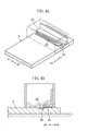
- the illustrated test piece supplying device 9 includes a container 91 containing a plurality of test pieces 90A, 90B, and also includes a movable body 92 for taking one test piece 90A at a time out of the container.
- the container 91 is provided with a blade 93 for preventing more than one test piece 90A, 90B from being simultaneously taken out of the container 91.
- the movable body 92 is formed with a groove 92a for accommodating one test piece 90A.
- the movable body 92 is moved to position the groove 92a at a site corresponding to the container 91, so that the test piece 90A is accommodated in the groove 92a. Then, as shown in Figs. 22B and 22C, the movable body 92 is moved in the direction A, and the test piece 90A is taken out of the container 91.
- the blade 93 sweeps away the test pieces 90B above the test piece 90A accommodated in the groove 92a, so that only the test piece 90A in the groove 92a is taken out of the container 91. In this way, the test piece 90A is taken out of the container and then is moved by the movable body 92 further in the direction A, to be supplied to a destination such as an optical checking position.
- test pieces 90A, 90B are stored together in a bottle. If the storing condition is not good, some of the test pieces 90A, 90B may undergo plastic deformation and may be warped (see 90A' in Fig. 23). As shown in Fig. 23, when placing such warped test piece 90A' into the groove 92a of the movable body 92, the test piece 90A' is not fully accommodated within the groove 92a, and a part of the test piece 90A' may protrude from the groove 92a.
- the blade 93 interferes with the portion of the test piece 90A' protruding out of the groove 92a, and scrapes the test piece 90A' off the groove 92a.
- the warped test piece 90A' cannot be taken out of the container 9 of the test piece supplying device 9.
- the probability of taking out the test pieces 90A, 90A', 90B is reduced, and thus the number of the test pieces 90A, 90A' , 90B to be taken out per unit time is reduced.
- An object of the present invention is to provide a test piece supplying device for taking test pieces out of a container containing a plurality of test pieces one by one, and for transferring it to a destination, so that the number of test pieces taken out of the container per unit time is increased, and that the probability of taking the test pieces out of the container is reduced as less as possible, even if a warped test piece is contained in the container.
- a test piece supplying device comprises a container for containing a plurality of test pieces and a movable body formed with a recess for accommodating one of the test pieces contained in the container.
- the container includes sweeping means for interfering with the test pieces located above the test piece accommodated in the recess, so that only one test piece is selectively accommodated in the recess when the movable body moves relative to the container.
- the sweeping means flattens the test strip to be accommodated in the recess so that the test piece is easily taken out of the container.
- the interfering or sweeping means includes a plate extending in a direction (e.g. a horizontal direction) intersecting with the vertical direction, and interfering with the test pieces above the test piece accommodated in the recess.
- the recess is elongated in a direction perpendicular to the transfer direction of the test piece.
- the plate includes an interference surface for interfering with the test pieces above the test piece accommodated in the recess, and the interference surface has a portion non-parallel to the elongated recess.
- the interference surface includes a linear portion inclined to the elongated recess, or a curved portion.
- the interfering means may include a plurality of interference portions projecting in a direction (e.g. a horizontal direction) intersecting with the vertical direction, and interfering with the test pieces above the test piece accommodated in the recess.
- At least a part of the plurality of interference portions project by different distances.
- the recess is elongated in a direction perpendicular to the transfer direction of the test piece, and at least a part of the plurality of interference portions are arranged so that shortest distances between tip ends of the interference portions and the recess are different from each other.
- the part of the plurality of interference portions are arranged in a straight or substantially straight line inclined relative to the elongated recess, or in a curve or a substantially curved line.
- the interfering means includes a plate extending in a direction perpendicular to the transfer direction, and the plurality of interference portions are provided by forming a plurality of cutouts at the plate.
- the plurality of interference portions may also be provided by fixing a plurality of pins to the interfering means .
- the interfering means may be provided with a plurality of pins projecting downward.
- the recess when the recess is elongated in the direction perpendicular to the transfer direction of the test piece, at least a part of the plurality of pins are arranged, so that the shortest distances between tip ends of the pins and the recess are different from each other, in a straight line or a substantially straight line inclined relative to the elongated recess, or in a curve or a substantially curved line.
- the movable body moves horizontally or rotates to take the test piece out of the container.
- Fig. 1 illustrates a test piece supplying device 1 which may be incorporated in or attached to an analyzing device in use, and the device transfers test pieces 2A, 2A', 2B in the A1 direction, as shown in Figs. 2A-2C and 3A, to supply these test pieces to e.g. an optical checking position.
- the test piece supplying device 1, including a movable body 3 and a container 4, is configured to supply the test pieces 2A, 2A', 2B each including a strip-shaped base 20 provided with a plurality of reagent pads 21.
- the movable body 3 includes a recess 30 for accommodating the test pieces 2A, 2B, and is movable relative to the container 4 in the directions A1, A2.
- the recess 30 is formed into dimensions corresponding to the outer configuration of the test pieces 2A, 2B, and is elongated in the directions B1, B2 perpendicular to the directions A1, A2.
- the recess 30 is moved between two positions, one of which is within the container 4 as shown in Fig. 2A, and the other is exposed out of the container 4 as shown in Fig. 2C.
- the movable body 3 is moved by a drive source such as a non-illustrated motor.
- the container 4 contains a plurality of test pieces 2A, 2B, and includes a body 40 serving as side surfaces of the container 4.
- the container 4 further includes sweeping means 41 and a bottom opening 42.
- the sweeping means 41 works so that more than one of the test pieces 2A, 2B are not taken out simultaneously.
- the sweeping means 41 includes an attaching portion 43 attached to the body 40 and a sweep function portion 44 extending in the direction A2.
- the sweep function portion 44 is a plate whose dimension measured in the direction A1 or A2 is reduced as proceeding in the direction B2.
- the sweep function portion 44 includes an interference surface 44a that is non-parallel to the elongated recess 30 of the movable body 3.
- the interference surface 44a interferes with the test piece 2B above the test piece 2A accommodated in the recess 30, and removes the test piece 2B therefrom.
- the test piece supplying device 1 can take the test piece 2A out of the container 4 by accommodating the test piece 2A in the recess 30 so that only this test piece 2A is allowed to pass below the sweep function portion 44.
- test pieces 2A, 2B contained in the container 4 contact the movable body 3 through the bottom opening 42 that is closed by the movable body 3.
- the interference surface 44a substantially defines an end of the bottom opening 42 at the side of the direction A1.
- the recess 30 of the movable body 3 is brought to a position within the container 4, and the test piece 2A is accommodated in the recess 30.
- the interference surface 44a of the sweep function portion 44 interferes with and sweeps away the test pieces 2B above the test piece 2A accommodated in the recess 30.
- the test piece 2A accommodated in the recess 30 does not come into contact with the interference surface 44a, but passes below the sweep function portion 44 as the movable body A1 moves in the direction A1, and is taken out of the container
- the test pieces 2A, 2B may be warped while stored in e.g. a bottle, and thus a warped test piece 2A' may be contained in the container 4.
- the warped test piece 2A' may be caught in the recess 30.
- the test piece supplying device 1 even such a warped test piece 2A' , once caught in the recess 30, is taken out of the container 4 as the movable body 3 is moved in the direction A1, as shown in Figs. 3-5, to be transferred to the optical checking position or any other destination.
- the sweep function portion 44 exerts a downward pressing force to the test piece 2A', and thus the part of the test piece 2A' protruding out of the recess 30 is flattened to be accommodated within the recess 30, whereby the test piece 2A' as a whole can pass below the sweep function portion 44. In this manner, in the test piece supplying device 1, even the warped test piece 2A' can be taken out of the container 4.
- the warped test piece 2A' is partly accommodated in the recess 30 at one end at the side of the direction B1, while partly protruding above the recess 30 at the other end at the side of the direction B2.
- the sweep function portion 44 scrapes the test piece 2A' out of the recess 30.
- the test piece 2A' is finally reversed and the test piece 2A' is partly accommodated in the recess 30 at the end on the side of the direction B1.
- the test piece 2A' can be taken out of the container by repeatedly moving the movable body, regardless of how the test piece 2A' is warped or oriented in the recess 30. Further, the test piece 2A' can be reliably reversed with a high probability when the sweep function portion 44 strikes the test strip 2A' off the recess 30. Thus, in the test piece supplying device 1, the warped test piece 2A' can be taken out of the container by a smaller number of movements.
- test piece supplying device 1 even the warped test piece 2A' is reliably taken out of the container 4. Thus, even if some warped test pieces 2A' are contained in the container 4, the test pieces 2A, 2A', 2B can still be taken out properly, thereby improving the efficiency in taking out the test pieces 2A, 2A', 2B from the container 4.
- the interference surface or edge 44a of the sweeping means 41 is inclined, though this may be variously modified.
- the sweeping means can be formed as illustrated in Figs. 6-13.
- the sweeping means 5A shown in Fig. 6 includes an interference surface 50 that is a combination of a flat surface 50a and an inclined surface 50b.
- the sweeping means 5B shown in Fig. 7 includes an interference surface 51 that is a combination of two inclined surfaces 51a forming a bending surface having an intermediate convex portion protruding in the direction A2.
- the sweeping means 5C shown in Fig. 8 includes an interference surface 52 that is a combination of two inclined surfaces 52a forming a bending surface having an intermediate concave portion retracting in the direction A1.
- the sweeping means 5D shown in Fig. 9 includes an interference surface 53 that is a combination of a plurality of inclined surfaces 53a forming corrugations each pointing sharply.
- the sweeping means 5F shown in Fig. 11 includes an interference surface 55 that is a convex surface protruding in the direction A2 and having an intermediate vertex.
- the sweeping means 5G shown in Fig. 12 includes an interference surface 56 that is a concave surface having an intermediate bottom retracting in the direction A1.
- the sweeping means 5H shown in Fig. 13 includes an interference surface 57 that is rippled.
- the sweeping means of the container may be formed as shown in Figs. 14A-14E, 15A-15D, 16A-16E, and 17-19.
- Each of sweeping means 6A-6I shown in Figs. 14A-14E, 15A-15D includes a respective one of the sweep function portions 60A-60I, respectively formed with a plurality of cutouts 61A-61I each elongated in the directions A1, A2 and arranged at intervals in the directions B1, B2.
- the sweeping means 6A-6I are respectively formed with a plurality of interference portions 62A-62I each projecting in the direction A2.
- the sweeping means 6A-6E shown in Figs. 14A-14E are made of the sweep function portions shown in Fig. 6-9, by forming the plurality of cutouts 61A-61E respectively.
- the sweeping means 6F-6I shown in Figs. 15A-15D are made of the sweep function portions shown in Fig. 10-13, by forming the plurality of cutouts 61F-61I respectively.
- the position, the number, and the dimension of the cutouts, and also the original form of the sweep function portions to be formed with the cutouts are not limited to the above-described examples, and these may be variously modified as long as the object of the present invention is attained.
- Each of sweeping means 7A-7E shown in Figs. 16A-16E includes a plurality of pins 70A-70E attached to a respective one of attaching portions 71A-71E in a manner such that the pins project in the direction A2 and are aligned in the directions B1, B2.
- Each of the pins 70A-70E includes a hemispheric tip end.
- the pins 70A-70E have tip ends differently positioned in the directions A1, A2.
- the positions of the pins 70A-70E generally correspond to the positions of the interference portions 62A-62E shown in Figs. 14A-14E.
- the pins may be positioned the same as or similarly to the positions of the interference portions 62F-62I shown in Figs. 15A-15D, or may be positioned otherwise as long as the object of the present invention is attained.
- the sweeping means 8 shown in Figs. 17-19 includes an attaching portion 81 provided with a plurality of pins 80 projecting downward therefrom.
- the pins 80 interferes with and removes the test piece brought right above the test piece accommodated in the recess 30 of the movable body 3.
- the attaching portion 81 fixes the pins 80 to the body 40 of the container 4, and includes a vertical portion 82 fixed to a wall 45 of the body 4 of the container 4, and also includes a horizontal portion 83 to which the pins 80 are fixed.
- the horizontal portion 83 is a plate whose dimension in the directions A1, A2 is reduced as proceeding in the direction B2, similarly to the sweep function portion 44 of the sweeping means 41 shown in Fig. 1.
- the pins 80 are fixed to the horizontal portion 83 along the end at the side of the direction A2. In other words, as well shown in Fig. 19, the pins 80 are positioned on a line inclined relative to the directions B1, B2.
- the pins may be fixed to the sweeping means 5A-5H shown in Figs. 6-13 along the ends at the side of the direction A2, or may be positioned otherwise as long as the object of the present invention is attained.
- the present invention may also be applied to a test piece supplying device 1' including a rotating body 3' rotating for taking a test piece out of the container 4.
- the interference surface of the sweeping means is formed as an inclined surface, though may be formed as the sweeping means described above with reference to Figs. 6-13.
- the sweeping means of the test piece supplying device 1' may be formed as the sweeping means described above with reference to Figs. 14-19, or may be formed otherwise as long as the object of the present invention is attained.
Abstract
Description
- The present invention relates to a test piece supplying device provided with a container that accommodates a plurality of test pieces, where the device is configured to pick an individual test piece from the container and transfer it to the desired site.
- Urine analysis is performed by utilizing an optical method, for example, whereby the reagent pad of a test piece is impregnated with urine, and then the color change of the pad is observed. Specifically, to check the coloring at the reagent pad, the test piece is first transferred to a portion where urine is dropped onto the reagent pad, and then transferred to an optical checking position. The test piece can be transferred to the urine application portion by utilizing a test piece supplying device (refer to
Patent documents - An example of such test piece supplying device is illustrated in Figs. 21 and 22A. The illustrated test
piece supplying device 9 includes acontainer 91 containing a plurality oftest pieces movable body 92 for taking onetest piece 90A at a time out of the container. Thecontainer 91 is provided with ablade 93 for preventing more than onetest piece container 91. Themovable body 92 is formed with agroove 92a for accommodating onetest piece 90A. - As shown in Fig. 22A, in the test
piece supplying device 9, themovable body 92 is moved to position thegroove 92a at a site corresponding to thecontainer 91, so that thetest piece 90A is accommodated in thegroove 92a. Then, as shown in Figs. 22B and 22C, themovable body 92 is moved in the direction A, and thetest piece 90A is taken out of thecontainer 91. Here, in thecontainer 91, theblade 93 sweeps away thetest pieces 90B above thetest piece 90A accommodated in thegroove 92a, so that only thetest piece 90A in thegroove 92a is taken out of thecontainer 91. In this way, thetest piece 90A is taken out of the container and then is moved by themovable body 92 further in the direction A, to be supplied to a destination such as an optical checking position. - Generally, the
test pieces test pieces test piece 90A' into thegroove 92a of themovable body 92, thetest piece 90A' is not fully accommodated within thegroove 92a, and a part of thetest piece 90A' may protrude from thegroove 92a. In this state, when themovable body 92 moves in the direction A, theblade 93 interferes with the portion of thetest piece 90A' protruding out of thegroove 92a, and scrapes thetest piece 90A' off thegroove 92a. In other words, the warpedtest piece 90A' cannot be taken out of thecontainer 9 of the testpiece supplying device 9. As seen from this, in the testpiece supplying device 9, when a warpedtest piece 90A' is contained in thecontainer 9, the probability of taking out thetest pieces test pieces - Patent Document: JP-A-11-118808
- Patent Document: JP-A-2000-35433
- An object of the present invention is to provide a test piece supplying device for taking test pieces out of a container containing a plurality of test pieces one by one, and for transferring it to a destination, so that the number of test pieces taken out of the container per unit time is increased, and that the probability of taking the test pieces out of the container is reduced as less as possible, even if a warped test piece is contained in the container.
- A test piece supplying device according to the present invention comprises a container for containing a plurality of test pieces and a movable body formed with a recess for accommodating one of the test pieces contained in the container. When the test piece is accommodated in the recess, the movable body moves relative to the container so that the test piece is taken out of the container one by one, the container includes sweeping means for interfering with the test pieces located above the test piece accommodated in the recess, so that only one test piece is selectively accommodated in the recess when the movable body moves relative to the container. When the movable body moves relative to the container with a warped test piece accommodated in the recess, the sweeping means flattens the test strip to be accommodated in the recess so that the test piece is easily taken out of the container.
- For example, the interfering or sweeping means includes a plate extending in a direction (e.g. a horizontal direction) intersecting with the vertical direction, and interfering with the test pieces above the test piece accommodated in the recess.
- For example, the recess is elongated in a direction perpendicular to the transfer direction of the test piece. In this case, the plate includes an interference surface for interfering with the test pieces above the test piece accommodated in the recess, and the interference surface has a portion non-parallel to the elongated recess. Preferably, the interference surface includes a linear portion inclined to the elongated recess, or a curved portion.
- The interfering means may include a plurality of interference portions projecting in a direction (e.g. a horizontal direction) intersecting with the vertical direction, and interfering with the test pieces above the test piece accommodated in the recess.
- At least a part of the plurality of interference portions project by different distances. For example, the recess is elongated in a direction perpendicular to the transfer direction of the test piece, and at least a part of the plurality of interference portions are arranged so that shortest distances between tip ends of the interference portions and the recess are different from each other. Preferably, the part of the plurality of interference portions are arranged in a straight or substantially straight line inclined relative to the elongated recess, or in a curve or a substantially curved line.
- For example, the interfering means includes a plate extending in a direction perpendicular to the transfer direction, and the plurality of interference portions are provided by forming a plurality of cutouts at the plate.
- The plurality of interference portions may also be provided by fixing a plurality of pins to the interfering means .
- The interfering means may be provided with a plurality of pins projecting downward. In this case, when the recess is elongated in the direction perpendicular to the transfer direction of the test piece, at least a part of the plurality of pins are arranged, so that the shortest distances between tip ends of the pins and the recess are different from each other, in a straight line or a substantially straight line inclined relative to the elongated recess, or in a curve or a substantially curved line.
- The movable body moves horizontally or rotates to take the test piece out of the container.
-
- Fig. 1 is an overall perspective view illustrating, partly transparently, an example of a test piece supplying device according to the present invention.
- Fig. 2 is a sectional view of a principal part of the test piece supplying device for illustrating its function.
- Fig. 3A is a perspective view of a principal part of the test piece supplying device of Fig. 1 for illustrating its function, and Fig. 3B is a sectional view of a principal part of the test piece supplying device of Fig. 1 for illustrating its function.
- Fig. 4A is a perspective view of a principal part of the test piece supplying device of Fig. 1 for illustrating its function, and Fig. 4B is a sectional view of a principal part of the test piece supplying device of Fig. 1 for illustrating its function.
- Fig. 5A is a perspective view of a principal part of the test piece supplying device of Fig. 1 for illustrating its function, and Fig. 5B is a sectional view of a principal part of the test piece supplying device of Fig. 1 for illustrating its function.
- Fig. 6 is a perspective view illustrating another example of sweeping means.
- Fig. 7 is a perspective view illustrating another example of the sweeping means.
- Fig. 8 is a perspective view illustrating another example of the sweeping means.
- Fig. 9 is a perspective view illustrating another example of the sweeping means.
- Fig. 10 is a perspective view illustrating another example of the sweeping means.
- Fig. 11 is a perspective view illustrating another example of the sweeping means.
- Fig. 12 is a perspective view illustrating another example of the sweeping means.
- Fig. 13 is a perspective view illustrating another example of the sweeping means.
- Fig. 14 is a perspective view illustrating another example of the sweeping means.
- Fig. 15 is a perspective view illustrating another example of the sweeping means.
- Fig. 16 is a perspective view illustrating another example of the sweeping means.
- Fig. 17 is a perspective view illustrating another example of the sweeping means.
- Fig. 18 is a sectional view taken along lines XVIII-XVIII in Fig. 17.
- Fig. 19 is a plan view illustrating the sweeping means of Figs. 17 and 18.
- Fig. 20 is a perspective view illustrating another example of the test piece supplying device.
- Fig. 21 is a perspective view illustrating an example of a conventional test piece supplying device.
- Fig. 22 is a sectional view illustrating the function of the test piece supplying device shown in Fig. 21.
- Fig. 23 is a perspective view illustrating the problem of the test piece supplying device shown in Fig. 21.
- Fig. 1 illustrates a test
piece supplying device 1 which may be incorporated in or attached to an analyzing device in use, and the device transferstest pieces piece supplying device 1, including amovable body 3 and acontainer 4, is configured to supply thetest pieces base 20 provided with a plurality ofreagent pads 21. - As shown in Fig. 1, the
movable body 3 includes arecess 30 for accommodating thetest pieces container 4 in the directions A1, A2. Therecess 30 is formed into dimensions corresponding to the outer configuration of thetest pieces movable body 3 in the directions A1, A2, therecess 30 is moved between two positions, one of which is within thecontainer 4 as shown in Fig. 2A, and the other is exposed out of thecontainer 4 as shown in Fig. 2C. Themovable body 3 is moved by a drive source such as a non-illustrated motor. - As shown in Figs. 1 and 2A, the
container 4 contains a plurality oftest pieces body 40 serving as side surfaces of thecontainer 4. Thecontainer 4 further includessweeping means 41 and abottom opening 42. - In taking the
test pieces container 4, the sweeping means 41 works so that more than one of thetest pieces portion 43 attached to thebody 40 and asweep function portion 44 extending in the direction A2. Thesweep function portion 44 is a plate whose dimension measured in the direction A1 or A2 is reduced as proceeding in the direction B2. In other words, thesweep function portion 44 includes aninterference surface 44a that is non-parallel to theelongated recess 30 of themovable body 3. When moving themovable body 3 in the direction A1 to position therecess 30 out of thecontainer 4, theinterference surface 44a interferes with thetest piece 2B above thetest piece 2A accommodated in therecess 30, and removes thetest piece 2B therefrom. In this way, the testpiece supplying device 1 can take thetest piece 2A out of thecontainer 4 by accommodating thetest piece 2A in therecess 30 so that only thistest piece 2A is allowed to pass below thesweep function portion 44. - The
test pieces container 4 contact themovable body 3 through thebottom opening 42 that is closed by themovable body 3. Theinterference surface 44a substantially defines an end of thebottom opening 42 at the side of the direction A1. - Next, the operation of taking out and transferring the test piece in the test
piece supplying device 1 is described with reference to Figs. 2A-2C. - As shown in Fig. 2A, in the test
piece supplying device 1, therecess 30 of themovable body 3 is brought to a position within thecontainer 4, and thetest piece 2A is accommodated in therecess 30. When themovable body 3 is moved in the direction A1 from the above-mentioned position, theinterference surface 44a of thesweep function portion 44 interferes with and sweeps away thetest pieces 2B above thetest piece 2A accommodated in therecess 30. At this stage, thetest piece 2A accommodated in therecess 30 does not come into contact with theinterference surface 44a, but passes below thesweep function portion 44 as the movable body A1 moves in the direction A1, and is taken out of the container - 4. By further moving the
movable body 3 in the direction A1, thetest piece 2A taken out of the container is next supplied to the desired site such as an optical checking position. - As described above, the
test pieces warped test piece 2A' may be contained in thecontainer 4. In this case, as shown in Figs. 3A and 3B, thewarped test piece 2A' may be caught in therecess 30. With the testpiece supplying device 1, even such awarped test piece 2A' , once caught in therecess 30, is taken out of thecontainer 4 as themovable body 3 is moved in the direction A1, as shown in Figs. 3-5, to be transferred to the optical checking position or any other destination. - More specifically, as shown in Figs. 3A and 3B, when the
test piece 2A' is accommodated in therecess 30, thetest piece 2A' partly protrudes above therecess 30. In this state, when themovable body 3 is moved in the direction A1, the part of thetest piece 2A' accommodated within therecess 30 is positioned below thesweep function portion 44, as shown in Figs. 4A and 4B. When themovable body 3 is further moved in the direction A1, thesweep function portion 44 exerts a downward pressing force to thetest piece 2A', and thus the part of thetest piece 2A' protruding out of therecess 30 is flattened to be accommodated within therecess 30, whereby thetest piece 2A' as a whole can pass below thesweep function portion 44. In this manner, in the testpiece supplying device 1, even thewarped test piece 2A' can be taken out of thecontainer 4. - In the illustrated example, the
warped test piece 2A' is partly accommodated in therecess 30 at one end at the side of the direction B1, while partly protruding above therecess 30 at the other end at the side of the direction B2. On the other hand, when thewarped test piece 2A' is partly accommodated in therecess 30 at one end at the side of the direction B2, while partly protruding above therecess 30 at the other end at the side of the direction B1, thesweep function portion 44 scrapes thetest piece 2A' out of therecess 30. However, after repeatedly moving the movable body, thetest piece 2A' is finally reversed and thetest piece 2A' is partly accommodated in therecess 30 at the end on the side of the direction B1. Thus, in the testpiece supplying device 1, thetest piece 2A' can be taken out of the container by repeatedly moving the movable body, regardless of how thetest piece 2A' is warped or oriented in therecess 30. Further, thetest piece 2A' can be reliably reversed with a high probability when thesweep function portion 44 strikes thetest strip 2A' off therecess 30. Thus, in the testpiece supplying device 1, thewarped test piece 2A' can be taken out of the container by a smaller number of movements. - As described above, in the test
piece supplying device 1, even thewarped test piece 2A' is reliably taken out of thecontainer 4. Thus, even if somewarped test pieces 2A' are contained in thecontainer 4, thetest pieces test pieces container 4. - In the above-described test
piece supplying device 1, the interference surface oredge 44a of the sweeping means 41 is inclined, though this may be variously modified. For example, the sweeping means can be formed as illustrated in Figs. 6-13. - The sweeping means 5A shown in Fig. 6 includes an
interference surface 50 that is a combination of aflat surface 50a and aninclined surface 50b. The sweeping means 5B shown in Fig. 7 includes aninterference surface 51 that is a combination of twoinclined surfaces 51a forming a bending surface having an intermediate convex portion protruding in the direction A2. The sweeping means 5C shown in Fig. 8 includes aninterference surface 52 that is a combination of twoinclined surfaces 52a forming a bending surface having an intermediate concave portion retracting in the direction A1. The sweeping means 5D shown in Fig. 9 includes aninterference surface 53 that is a combination of a plurality ofinclined surfaces 53a forming corrugations each pointing sharply. The sweeping means 5E shown in Fig. 10 includes aninterference surface 54 that is a smoothly curved surface bulging in the direction A2 at an end on the side of the direction B1. The sweeping means 5F shown in Fig. 11 includes aninterference surface 55 that is a convex surface protruding in the direction A2 and having an intermediate vertex. The sweeping means 5G shown in Fig. 12 includes aninterference surface 56 that is a concave surface having an intermediate bottom retracting in the direction A1. The sweeping means 5H shown in Fig. 13 includes aninterference surface 57 that is rippled. - Further, the sweeping means of the container may be formed as shown in Figs. 14A-14E, 15A-15D, 16A-16E, and 17-19.
- Each of
sweeping means 6A-6I shown in Figs. 14A-14E, 15A-15D includes a respective one of thesweep function portions 60A-60I, respectively formed with a plurality ofcutouts 61A-61I each elongated in the directions A1, A2 and arranged at intervals in the directions B1, B2. In other words, the sweeping means 6A-6I are respectively formed with a plurality ofinterference portions 62A-62I each projecting in the direction A2. - The sweeping means 6A-6E shown in Figs. 14A-14E are made of the sweep function portions shown in Fig. 6-9, by forming the plurality of
cutouts 61A-61E respectively. The sweeping means 6F-6I shown in Figs. 15A-15D are made of the sweep function portions shown in Fig. 10-13, by forming the plurality ofcutouts 61F-61I respectively. - Of course, the position, the number, and the dimension of the cutouts, and also the original form of the sweep function portions to be formed with the cutouts are not limited to the above-described examples, and these may be variously modified as long as the object of the present invention is attained.
- Each of
sweeping means 7A-7E shown in Figs. 16A-16E includes a plurality ofpins 70A-70E attached to a respective one of attachingportions 71A-71E in a manner such that the pins project in the direction A2 and are aligned in the directions B1, B2. Each of thepins 70A-70E includes a hemispheric tip end. - In the illustrated
sweeping means 7A-7E, at least a part of thepins 70A-70E have tip ends differently positioned in the directions A1, A2. The positions of thepins 70A-70E generally correspond to the positions of theinterference portions 62A-62E shown in Figs. 14A-14E. - Of course, the pins may be positioned the same as or similarly to the positions of the
interference portions 62F-62I shown in Figs. 15A-15D, or may be positioned otherwise as long as the object of the present invention is attained. - The sweeping means 8 shown in Figs. 17-19 includes an attaching
portion 81 provided with a plurality ofpins 80 projecting downward therefrom. - The
pins 80 interferes with and removes the test piece brought right above the test piece accommodated in therecess 30 of themovable body 3. The attachingportion 81 fixes thepins 80 to thebody 40 of thecontainer 4, and includes avertical portion 82 fixed to awall 45 of thebody 4 of thecontainer 4, and also includes ahorizontal portion 83 to which thepins 80 are fixed. - The
horizontal portion 83 is a plate whose dimension in the directions A1, A2 is reduced as proceeding in the direction B2, similarly to thesweep function portion 44 of the sweeping means 41 shown in Fig. 1. Thepins 80 are fixed to thehorizontal portion 83 along the end at the side of the direction A2. In other words, as well shown in Fig. 19, thepins 80 are positioned on a line inclined relative to the directions B1, B2. - Of course, the pins may be fixed to the sweeping means 5A-5H shown in Figs. 6-13 along the ends at the side of the direction A2, or may be positioned otherwise as long as the object of the present invention is attained.
- As shown in Fig. 20, the present invention may also be applied to a test piece supplying device 1' including a rotating body 3' rotating for taking a test piece out of the
container 4. In the test piece supplying device 1' shown Fig. 20, the interference surface of the sweeping means is formed as an inclined surface, though may be formed as the sweeping means described above with reference to Figs. 6-13. Further, the sweeping means of the test piece supplying device 1' may be formed as the sweeping means described above with reference to Figs. 14-19, or may be formed otherwise as long as the object of the present invention is attained.
Claims (16)
- A test piece supplying device comprising: a container for containing a plurality of test pieces; and a movable body formed with a recess for accommodating one of the test pieces contained in the container; the movable body being moved relative to the container with one test piece accommodated in the recess, so that the test pieces, one at a time, are taken out of the container,
wherein the container is provided with interfering means that interferes with test pieces above the test piece in the recess when the movable body moves relative to the container, so that one test piece is selectively accommodated in the recess,
wherein when the movable body moves relative to the container with a warped test piece accommodated in the recess, the interfering means causes the test piece to be accommodated in the recess with the warp amended, so that the test piece is taken out of the container. - The test piece supplying device according to claim 1, wherein the interfering means includes a plate that extends in a direction intersecting a vertical direction and interferes with test pieces above the test piece accommodated in the recess.
- The test piece supplying device according to claim 2, wherein the plate extends in a horizontal direction.
- The test piece supplying device according to claim2, wherein the recess is elongated in a direction perpendicular to a transfer direction of the test piece,
wherein the plate includes an interference surface for interfering with the test pieces above the test piece accommodated in the recess, the interference surface having a portion non-parallel to the elongated recess. - The test piece supplying device according to claim 4, wherein the interference surface includes a linear portion inclined to the elongated recess or a curved portion.
- The test piece supplying device according to claim 1, wherein the interfering means includes a plurality of interference portions projecting in a direction intersecting a vertical direction, the interference portions interfering with the test pieces above the test piece accommodated in the recess.
- The test piece supplying device according to claim 6, wherein at least a part of the plurality of interference portions project by different distances.
- The test piece supplying device according to claim 6, wherein the recess is elongated in a direction perpendicular to the transfer direction of the test piece,
wherein at least a part of the plurality of interference portions are arranged so that shortest distances between tip ends of the interference portions and the recess are different from each other. - The test piece supplying device according to claim 8, wherein the part of the plurality of interference portions are arranged in a straight line or a substantially straight line inclined relative to the elongated recess, or in a curve or a substantially curved line.
- The test piece supplying device according to claim 6, wherein the interfering means includes a plate extending in a direction perpendicular to the transfer direction,
wherein the plurality of interference portions are provided by forming a plurality of cutouts in the plate. - The test piece supplying device according to claim 10, wherein the plate extends in a horizontal direction.
- The test piece supplying device according to claim 6, wherein the plurality of interference portions are provided by fixing a plurality of pins to the interfering means.
- The test piece supplying device according to claim 1, wherein the recess is elongated in the direction perpendicular to the transfer direction of the test piece,
wherein the interfering means are provided with a plurality of pins projecting downward,
wherein at least a part of the plurality of pins are arranged so that the shortest distances between tip ends of the pins and the recess are different from each other. - The test piece supplying device according to claim 13, wherein the part of the plurality of pins are arranged in a straight or substantially straight line inclined relative to the elongated recess, or in a curve or substantially curved line.
- The test piece supplying device according to claim 1, wherein the movable body moves horizontally to take the test piece out of the container.
- The test piece supplying device according to claim 1, wherein the movable body rotates to take the test piece out of the container.
Applications Claiming Priority (2)
| Application Number | Priority Date | Filing Date | Title |
|---|---|---|---|
| JP2003362420 | 2003-10-22 | ||
| PCT/JP2004/015414 WO2005040834A1 (en) | 2003-10-22 | 2004-10-19 | Analyzer-supplying device |
Publications (3)
| Publication Number | Publication Date |
|---|---|
| EP1677116A1 true EP1677116A1 (en) | 2006-07-05 |
| EP1677116A4 EP1677116A4 (en) | 2011-12-14 |
| EP1677116B1 EP1677116B1 (en) | 2014-06-11 |
Family
ID=34509983
Family Applications (1)
| Application Number | Title | Priority Date | Filing Date |
|---|---|---|---|
| EP04792583.9A Not-in-force EP1677116B1 (en) | 2003-10-22 | 2004-10-19 | Analyzer-supplying device |
Country Status (4)
| Country | Link |
|---|---|
| EP (1) | EP1677116B1 (en) |
| JP (1) | JP4660687B2 (en) |
| CN (1) | CN1871520B (en) |
| WO (1) | WO2005040834A1 (en) |
Families Citing this family (2)
| Publication number | Priority date | Publication date | Assignee | Title |
|---|---|---|---|---|
| JP6349992B2 (en) * | 2014-06-13 | 2018-07-04 | 日本精工株式会社 | A workpiece removal device and a method of manufacturing a linear guide device using the workpiece removal device. |
| JP6544465B2 (en) * | 2018-05-11 | 2019-07-17 | 日本精工株式会社 | Patent application title: Workpiece pick-up device, and method of manufacturing linear guide device using work pick-up device |
Citations (4)
| Publication number | Priority date | Publication date | Assignee | Title |
|---|---|---|---|---|
| US4796744A (en) * | 1986-07-30 | 1989-01-10 | Hoechst Aktiengesellschaft | Apparatus for separating test strips |
| US4876204A (en) * | 1984-10-11 | 1989-10-24 | Kabushiki Kaisha Kyoto Daiichi Kagaku | Method and apparatus of automatic continuous analysis using analytical implement |
| JPH0558527A (en) * | 1991-09-02 | 1993-03-09 | Canon Inc | Sheet discharging device |
| US5298425A (en) * | 1992-02-13 | 1994-03-29 | Boehringer Mannheim Gmbh | Device for the positionally correct feeding of test strips to an analysis unit |
Family Cites Families (13)
| Publication number | Priority date | Publication date | Assignee | Title |
|---|---|---|---|---|
| JPH0665990B2 (en) * | 1984-11-05 | 1994-08-24 | 株式会社京都第一科学 | Method and apparatus for automatically supplying strip-shaped test strips for automatic analysis in body fluid component analysis |
| JPH0724852B2 (en) * | 1985-11-01 | 1995-03-22 | 日本鋼管株式会社 | Rolled material warpage control device |
| JPS63150955A (en) * | 1986-12-15 | 1988-06-23 | Hitachi Medical Corp | Measuring circuit for x-ray ct apparatus |
| JPH05264540A (en) * | 1992-03-18 | 1993-10-12 | Hitachi Ltd | Drum container for automatic urine analyzer |
| JP2954436B2 (en) * | 1992-11-11 | 1999-09-27 | 株式会社日立製作所 | Test piece supply device and analyzer using the same |
| JP3065197B2 (en) * | 1993-05-17 | 2000-07-12 | 富士写真フイルム株式会社 | Cartridge for storing dry analytical film pieces |
| JP3036353B2 (en) * | 1994-05-11 | 2000-04-24 | 株式会社日立製作所 | Test piece supply device |
| JPH1012332A (en) * | 1996-06-25 | 1998-01-16 | Fujitsu Takamizawa Component Kk | Manufacture of card connector and the card |
| JPH11118808A (en) | 1997-10-17 | 1999-04-30 | Kdk Corp | Analyzer |
| JP3393403B2 (en) * | 1998-07-17 | 2003-04-07 | アークレイ株式会社 | Test piece supply device |
| GB0021219D0 (en) * | 2000-08-30 | 2000-10-18 | Hypoguard Ltd | Test device |
| JP3920015B2 (en) * | 2000-09-14 | 2007-05-30 | 東京エレクトロン株式会社 | Si substrate processing method |
| CN107073528B (en) * | 2014-10-28 | 2019-09-10 | 杰富意钢铁株式会社 | Washer fluid spraying apparatus and cleaning solution injection method |
-
2004
- 2004-10-19 WO PCT/JP2004/015414 patent/WO2005040834A1/en active Application Filing
- 2004-10-19 JP JP2005514946A patent/JP4660687B2/en not_active Expired - Fee Related
- 2004-10-19 CN CN2004800311715A patent/CN1871520B/en not_active Expired - Fee Related
- 2004-10-19 EP EP04792583.9A patent/EP1677116B1/en not_active Not-in-force
Patent Citations (4)
| Publication number | Priority date | Publication date | Assignee | Title |
|---|---|---|---|---|
| US4876204A (en) * | 1984-10-11 | 1989-10-24 | Kabushiki Kaisha Kyoto Daiichi Kagaku | Method and apparatus of automatic continuous analysis using analytical implement |
| US4796744A (en) * | 1986-07-30 | 1989-01-10 | Hoechst Aktiengesellschaft | Apparatus for separating test strips |
| JPH0558527A (en) * | 1991-09-02 | 1993-03-09 | Canon Inc | Sheet discharging device |
| US5298425A (en) * | 1992-02-13 | 1994-03-29 | Boehringer Mannheim Gmbh | Device for the positionally correct feeding of test strips to an analysis unit |
Non-Patent Citations (1)
| Title |
|---|
| See also references of WO2005040834A1 * |
Also Published As
| Publication number | Publication date |
|---|---|
| JPWO2005040834A1 (en) | 2007-04-19 |
| WO2005040834A1 (en) | 2005-05-06 |
| CN1871520B (en) | 2012-06-06 |
| EP1677116A4 (en) | 2011-12-14 |
| JP4660687B2 (en) | 2011-03-30 |
| EP1677116B1 (en) | 2014-06-11 |
| CN1871520A (en) | 2006-11-29 |
Similar Documents
| Publication | Publication Date | Title |
|---|---|---|
| CN1275196C (en) | Memory card | |
| CN104385289A (en) | Robot gripping device | |
| EP2269774A3 (en) | Fastener tool | |
| EP1677116A1 (en) | Analyzer-supplying device | |
| US7862772B2 (en) | Analyzer-supplying device | |
| JP5206027B2 (en) | Medical equipment | |
| EP1477226A1 (en) | Test tube for storing fluid | |
| WO2000005595A1 (en) | Grinding chip | |
| US5026526A (en) | Automated capping means for analyzer pipette | |
| EP2098295B1 (en) | Cap for microtube for pharmaceutical development | |
| US20210239720A1 (en) | Assay reaction controller magazine | |
| JP4576549B2 (en) | Analysis tool orientation selection mechanism and analyzer | |
| US20020153421A1 (en) | Hybrid card contact actuator system and method | |
| JP4704843B2 (en) | probe | |
| JPH08138812A (en) | Ic socket | |
| JP5155950B2 (en) | Control board case | |
| US6590779B2 (en) | Pop-up mechanism and a PC card having it | |
| JP2003007415A (en) | Socket for semiconductor package | |
| JP2019117071A (en) | Dispensing method | |
| JPH0750366A (en) | Socket | |
| EP0895179A3 (en) | Connector device for ic card | |
| CN107860908B (en) | Biochemical detection kit for detection and analysis | |
| CN108382899A (en) | A kind of storage card automatic propelling device | |
| US7080952B2 (en) | Pen | |
| US6968605B2 (en) | Tagging apparatus and method |
Legal Events
| Date | Code | Title | Description |
|---|---|---|---|
| PUAI | Public reference made under article 153(3) epc to a published international application that has entered the european phase |
Free format text: ORIGINAL CODE: 0009012 |
|
| 17P | Request for examination filed |
Effective date: 20060424 |
|
| AK | Designated contracting states |
Kind code of ref document: A1 Designated state(s): AT BE BG CH CY CZ DE DK EE ES FI FR GB GR HU IE IT LI LU MC NL PL PT RO SE SI SK TR |
|
| DAX | Request for extension of the european patent (deleted) | ||
| A4 | Supplementary search report drawn up and despatched |
Effective date: 20111116 |
|
| RIC1 | Information provided on ipc code assigned before grant |
Ipc: G01N 33/487 20060101ALI20111110BHEP Ipc: G01N 1/00 20060101ALI20111110BHEP Ipc: G01N 35/04 20060101AFI20111110BHEP |
|
| 17Q | First examination report despatched |
Effective date: 20120920 |
|
| REG | Reference to a national code |
Ref country code: DE Ref legal event code: R079 Ref document number: 602004045259 Country of ref document: DE Free format text: PREVIOUS MAIN CLASS: G01N0035040000 Ipc: G01N0035000000 |
|
| RIC1 | Information provided on ipc code assigned before grant |
Ipc: G01N 1/00 20060101ALI20130906BHEP Ipc: G01N 35/00 20060101AFI20130906BHEP Ipc: G01N 35/04 20060101ALI20130906BHEP Ipc: G01N 33/487 20060101ALI20130906BHEP |
|
| GRAP | Despatch of communication of intention to grant a patent |
Free format text: ORIGINAL CODE: EPIDOSNIGR1 |
|
| INTG | Intention to grant announced |
Effective date: 20140109 |
|
| GRAS | Grant fee paid |
Free format text: ORIGINAL CODE: EPIDOSNIGR3 |
|
| GRAA | (expected) grant |
Free format text: ORIGINAL CODE: 0009210 |
|
| AK | Designated contracting states |
Kind code of ref document: B1 Designated state(s): AT BE BG CH CY CZ DE DK EE ES FI FR GB GR HU IE IT LI LU MC NL PL PT RO SE SI SK TR |
|
| REG | Reference to a national code |
Ref country code: GB Ref legal event code: FG4D |
|
| REG | Reference to a national code |
Ref country code: CH Ref legal event code: EP |
|
| REG | Reference to a national code |
Ref country code: IE Ref legal event code: FG4D |
|
| REG | Reference to a national code |
Ref country code: AT Ref legal event code: REF Ref document number: 672503 Country of ref document: AT Kind code of ref document: T Effective date: 20140715 |
|
| REG | Reference to a national code |
Ref country code: DE Ref legal event code: R096 Ref document number: 602004045259 Country of ref document: DE Effective date: 20140724 |
|
| PG25 | Lapsed in a contracting state [announced via postgrant information from national office to epo] |
Ref country code: FI Free format text: LAPSE BECAUSE OF FAILURE TO SUBMIT A TRANSLATION OF THE DESCRIPTION OR TO PAY THE FEE WITHIN THE PRESCRIBED TIME-LIMIT Effective date: 20140611 Ref country code: GR Free format text: LAPSE BECAUSE OF FAILURE TO SUBMIT A TRANSLATION OF THE DESCRIPTION OR TO PAY THE FEE WITHIN THE PRESCRIBED TIME-LIMIT Effective date: 20140912 |
|
| REG | Reference to a national code |
Ref country code: NL Ref legal event code: VDEP Effective date: 20140611 |
|
| REG | Reference to a national code |
Ref country code: AT Ref legal event code: MK05 Ref document number: 672503 Country of ref document: AT Kind code of ref document: T Effective date: 20140611 |
|
| PG25 | Lapsed in a contracting state [announced via postgrant information from national office to epo] |
Ref country code: SE Free format text: LAPSE BECAUSE OF FAILURE TO SUBMIT A TRANSLATION OF THE DESCRIPTION OR TO PAY THE FEE WITHIN THE PRESCRIBED TIME-LIMIT Effective date: 20140611 |
|
| PG25 | Lapsed in a contracting state [announced via postgrant information from national office to epo] |
Ref country code: EE Free format text: LAPSE BECAUSE OF FAILURE TO SUBMIT A TRANSLATION OF THE DESCRIPTION OR TO PAY THE FEE WITHIN THE PRESCRIBED TIME-LIMIT Effective date: 20140611 Ref country code: PT Free format text: LAPSE BECAUSE OF FAILURE TO SUBMIT A TRANSLATION OF THE DESCRIPTION OR TO PAY THE FEE WITHIN THE PRESCRIBED TIME-LIMIT Effective date: 20141013 Ref country code: CZ Free format text: LAPSE BECAUSE OF FAILURE TO SUBMIT A TRANSLATION OF THE DESCRIPTION OR TO PAY THE FEE WITHIN THE PRESCRIBED TIME-LIMIT Effective date: 20140611 Ref country code: ES Free format text: LAPSE BECAUSE OF FAILURE TO SUBMIT A TRANSLATION OF THE DESCRIPTION OR TO PAY THE FEE WITHIN THE PRESCRIBED TIME-LIMIT Effective date: 20140611 Ref country code: SK Free format text: LAPSE BECAUSE OF FAILURE TO SUBMIT A TRANSLATION OF THE DESCRIPTION OR TO PAY THE FEE WITHIN THE PRESCRIBED TIME-LIMIT Effective date: 20140611 Ref country code: RO Free format text: LAPSE BECAUSE OF FAILURE TO SUBMIT A TRANSLATION OF THE DESCRIPTION OR TO PAY THE FEE WITHIN THE PRESCRIBED TIME-LIMIT Effective date: 20140611 |
|
| PG25 | Lapsed in a contracting state [announced via postgrant information from national office to epo] |
Ref country code: PL Free format text: LAPSE BECAUSE OF FAILURE TO SUBMIT A TRANSLATION OF THE DESCRIPTION OR TO PAY THE FEE WITHIN THE PRESCRIBED TIME-LIMIT Effective date: 20140611 Ref country code: AT Free format text: LAPSE BECAUSE OF FAILURE TO SUBMIT A TRANSLATION OF THE DESCRIPTION OR TO PAY THE FEE WITHIN THE PRESCRIBED TIME-LIMIT Effective date: 20140611 Ref country code: NL Free format text: LAPSE BECAUSE OF FAILURE TO SUBMIT A TRANSLATION OF THE DESCRIPTION OR TO PAY THE FEE WITHIN THE PRESCRIBED TIME-LIMIT Effective date: 20140611 |
|
| REG | Reference to a national code |
Ref country code: DE Ref legal event code: R097 Ref document number: 602004045259 Country of ref document: DE |
|
| PLBE | No opposition filed within time limit |
Free format text: ORIGINAL CODE: 0009261 |
|
| STAA | Information on the status of an ep patent application or granted ep patent |
Free format text: STATUS: NO OPPOSITION FILED WITHIN TIME LIMIT |
|
| PG25 | Lapsed in a contracting state [announced via postgrant information from national office to epo] |
Ref country code: DK Free format text: LAPSE BECAUSE OF FAILURE TO SUBMIT A TRANSLATION OF THE DESCRIPTION OR TO PAY THE FEE WITHIN THE PRESCRIBED TIME-LIMIT Effective date: 20140611 |
|
| 26N | No opposition filed |
Effective date: 20150312 |
|
| PG25 | Lapsed in a contracting state [announced via postgrant information from national office to epo] |
Ref country code: MC Free format text: LAPSE BECAUSE OF FAILURE TO SUBMIT A TRANSLATION OF THE DESCRIPTION OR TO PAY THE FEE WITHIN THE PRESCRIBED TIME-LIMIT Effective date: 20140611 Ref country code: LU Free format text: LAPSE BECAUSE OF FAILURE TO SUBMIT A TRANSLATION OF THE DESCRIPTION OR TO PAY THE FEE WITHIN THE PRESCRIBED TIME-LIMIT Effective date: 20141019 |
|
| REG | Reference to a national code |
Ref country code: CH Ref legal event code: PL |
|
| REG | Reference to a national code |
Ref country code: DE Ref legal event code: R097 Ref document number: 602004045259 Country of ref document: DE Effective date: 20150312 |
|
| REG | Reference to a national code |
Ref country code: IE Ref legal event code: MM4A |
|
| PG25 | Lapsed in a contracting state [announced via postgrant information from national office to epo] |
Ref country code: CH Free format text: LAPSE BECAUSE OF NON-PAYMENT OF DUE FEES Effective date: 20141031 Ref country code: LI Free format text: LAPSE BECAUSE OF NON-PAYMENT OF DUE FEES Effective date: 20141031 Ref country code: SI Free format text: LAPSE BECAUSE OF FAILURE TO SUBMIT A TRANSLATION OF THE DESCRIPTION OR TO PAY THE FEE WITHIN THE PRESCRIBED TIME-LIMIT Effective date: 20140611 |
|
| REG | Reference to a national code |
Ref country code: FR Ref legal event code: PLFP Year of fee payment: 12 |
|
| PG25 | Lapsed in a contracting state [announced via postgrant information from national office to epo] |
Ref country code: IE Free format text: LAPSE BECAUSE OF NON-PAYMENT OF DUE FEES Effective date: 20141019 |
|
| PGFP | Annual fee paid to national office [announced via postgrant information from national office to epo] |
Ref country code: GB Payment date: 20151021 Year of fee payment: 12 Ref country code: IT Payment date: 20151028 Year of fee payment: 12 Ref country code: DE Payment date: 20151022 Year of fee payment: 12 |
|
| PGFP | Annual fee paid to national office [announced via postgrant information from national office to epo] |
Ref country code: FR Payment date: 20151023 Year of fee payment: 12 |
|
| PG25 | Lapsed in a contracting state [announced via postgrant information from national office to epo] |
Ref country code: BG Free format text: LAPSE BECAUSE OF FAILURE TO SUBMIT A TRANSLATION OF THE DESCRIPTION OR TO PAY THE FEE WITHIN THE PRESCRIBED TIME-LIMIT Effective date: 20140611 |
|
| PG25 | Lapsed in a contracting state [announced via postgrant information from national office to epo] |
Ref country code: CY Free format text: LAPSE BECAUSE OF FAILURE TO SUBMIT A TRANSLATION OF THE DESCRIPTION OR TO PAY THE FEE WITHIN THE PRESCRIBED TIME-LIMIT Effective date: 20140611 |
|
| PG25 | Lapsed in a contracting state [announced via postgrant information from national office to epo] |
Ref country code: HU Free format text: LAPSE BECAUSE OF FAILURE TO SUBMIT A TRANSLATION OF THE DESCRIPTION OR TO PAY THE FEE WITHIN THE PRESCRIBED TIME-LIMIT; INVALID AB INITIO Effective date: 20041019 Ref country code: TR Free format text: LAPSE BECAUSE OF FAILURE TO SUBMIT A TRANSLATION OF THE DESCRIPTION OR TO PAY THE FEE WITHIN THE PRESCRIBED TIME-LIMIT Effective date: 20140611 Ref country code: BE Free format text: LAPSE BECAUSE OF FAILURE TO SUBMIT A TRANSLATION OF THE DESCRIPTION OR TO PAY THE FEE WITHIN THE PRESCRIBED TIME-LIMIT Effective date: 20140611 |
|
| REG | Reference to a national code |
Ref country code: DE Ref legal event code: R119 Ref document number: 602004045259 Country of ref document: DE |
|
| GBPC | Gb: european patent ceased through non-payment of renewal fee |
Effective date: 20161019 |
|
| REG | Reference to a national code |
Ref country code: FR Ref legal event code: ST Effective date: 20170630 |
|
| PG25 | Lapsed in a contracting state [announced via postgrant information from national office to epo] |
Ref country code: FR Free format text: LAPSE BECAUSE OF NON-PAYMENT OF DUE FEES Effective date: 20161102 Ref country code: DE Free format text: LAPSE BECAUSE OF NON-PAYMENT OF DUE FEES Effective date: 20170503 Ref country code: GB Free format text: LAPSE BECAUSE OF NON-PAYMENT OF DUE FEES Effective date: 20161019 |
|
| PG25 | Lapsed in a contracting state [announced via postgrant information from national office to epo] |
Ref country code: IT Free format text: LAPSE BECAUSE OF NON-PAYMENT OF DUE FEES Effective date: 20161019 |