EP1673024B1 - Multi-axial orthopedic device and system, e.g. for spinal surgery - Google Patents
Multi-axial orthopedic device and system, e.g. for spinal surgery Download PDFInfo
- Publication number
- EP1673024B1 EP1673024B1 EP04781811.7A EP04781811A EP1673024B1 EP 1673024 B1 EP1673024 B1 EP 1673024B1 EP 04781811 A EP04781811 A EP 04781811A EP 1673024 B1 EP1673024 B1 EP 1673024B1
- Authority
- EP
- European Patent Office
- Prior art keywords
- base member
- receiver
- receiver member
- bone anchoring
- opening
- Prior art date
- Legal status (The legal status is an assumption and is not a legal conclusion. Google has not performed a legal analysis and makes no representation as to the accuracy of the status listed.)
- Active
Links
- 230000000399 orthopedic effect Effects 0.000 title claims description 21
- 238000001356 surgical procedure Methods 0.000 title description 7
- 210000000988 bone and bone Anatomy 0.000 claims description 88
- 238000004873 anchoring Methods 0.000 claims description 57
- 239000007943 implant Substances 0.000 claims description 36
- 238000003780 insertion Methods 0.000 claims description 7
- 230000037431 insertion Effects 0.000 claims description 7
- 229910001285 shape-memory alloy Inorganic materials 0.000 claims description 3
- 230000006835 compression Effects 0.000 description 12
- 238000007906 compression Methods 0.000 description 12
- 230000008859 change Effects 0.000 description 4
- 238000012937 correction Methods 0.000 description 4
- 229910001000 nickel titanium Inorganic materials 0.000 description 4
- 208000027418 Wounds and injury Diseases 0.000 description 3
- 230000006378 damage Effects 0.000 description 3
- 230000035876 healing Effects 0.000 description 3
- 208000014674 injury Diseases 0.000 description 3
- 210000001519 tissue Anatomy 0.000 description 3
- 102100033337 PDZ and LIM domain protein 7 Human genes 0.000 description 2
- 101710121660 PDZ and LIM domain protein 7 Proteins 0.000 description 2
- 238000004891 communication Methods 0.000 description 2
- 238000005553 drilling Methods 0.000 description 2
- 230000006870 function Effects 0.000 description 2
- 230000001976 improved effect Effects 0.000 description 2
- 230000036244 malformation Effects 0.000 description 2
- 238000012986 modification Methods 0.000 description 2
- 230000004048 modification Effects 0.000 description 2
- 230000000921 morphogenic effect Effects 0.000 description 2
- HLXZNVUGXRDIFK-UHFFFAOYSA-N nickel titanium Chemical compound [Ti].[Ti].[Ti].[Ti].[Ti].[Ti].[Ti].[Ti].[Ti].[Ti].[Ti].[Ni].[Ni].[Ni].[Ni].[Ni].[Ni].[Ni].[Ni].[Ni].[Ni].[Ni].[Ni].[Ni].[Ni] HLXZNVUGXRDIFK-UHFFFAOYSA-N 0.000 description 2
- 230000001737 promoting effect Effects 0.000 description 2
- 102000004169 proteins and genes Human genes 0.000 description 2
- 108090000623 proteins and genes Proteins 0.000 description 2
- 238000010079 rubber tapping Methods 0.000 description 2
- 239000000126 substance Substances 0.000 description 2
- 230000008093 supporting effect Effects 0.000 description 2
- 230000001225 therapeutic effect Effects 0.000 description 2
- 208000010392 Bone Fractures Diseases 0.000 description 1
- RTAQQCXQSZGOHL-UHFFFAOYSA-N Titanium Chemical compound [Ti] RTAQQCXQSZGOHL-UHFFFAOYSA-N 0.000 description 1
- HZEWFHLRYVTOIW-UHFFFAOYSA-N [Ti].[Ni] Chemical compound [Ti].[Ni] HZEWFHLRYVTOIW-UHFFFAOYSA-N 0.000 description 1
- 230000002159 abnormal effect Effects 0.000 description 1
- 229910045601 alloy Inorganic materials 0.000 description 1
- 239000000956 alloy Substances 0.000 description 1
- 230000004075 alteration Effects 0.000 description 1
- 238000013459 approach Methods 0.000 description 1
- 239000000560 biocompatible material Substances 0.000 description 1
- 230000008468 bone growth Effects 0.000 description 1
- 210000002805 bone matrix Anatomy 0.000 description 1
- 239000000969 carrier Substances 0.000 description 1
- 238000010276 construction Methods 0.000 description 1
- 238000002513 implantation Methods 0.000 description 1
- 238000007373 indentation Methods 0.000 description 1
- 230000001939 inductive effect Effects 0.000 description 1
- 230000002452 interceptive effect Effects 0.000 description 1
- 230000013011 mating Effects 0.000 description 1
- 210000002901 mesenchymal stem cell Anatomy 0.000 description 1
- 238000000034 method Methods 0.000 description 1
- 239000000203 mixture Substances 0.000 description 1
- 229920003023 plastic Polymers 0.000 description 1
- 239000004033 plastic Substances 0.000 description 1
- 230000008569 process Effects 0.000 description 1
- 230000009467 reduction Effects 0.000 description 1
- 125000006850 spacer group Chemical group 0.000 description 1
- 230000006641 stabilisation Effects 0.000 description 1
- 238000011105 stabilization Methods 0.000 description 1
- 230000000087 stabilizing effect Effects 0.000 description 1
- 229910001220 stainless steel Inorganic materials 0.000 description 1
- 239000010935 stainless steel Substances 0.000 description 1
- 229920002994 synthetic fiber Polymers 0.000 description 1
- 238000002560 therapeutic procedure Methods 0.000 description 1
- 210000000115 thoracic cavity Anatomy 0.000 description 1
- 229910052719 titanium Inorganic materials 0.000 description 1
- 239000010936 titanium Substances 0.000 description 1
Images


Classifications
-
- A—HUMAN NECESSITIES
- A61—MEDICAL OR VETERINARY SCIENCE; HYGIENE
- A61B—DIAGNOSIS; SURGERY; IDENTIFICATION
- A61B17/00—Surgical instruments, devices or methods, e.g. tourniquets
- A61B17/56—Surgical instruments or methods for treatment of bones or joints; Devices specially adapted therefor
- A61B17/58—Surgical instruments or methods for treatment of bones or joints; Devices specially adapted therefor for osteosynthesis, e.g. bone plates, screws, setting implements or the like
- A61B17/68—Internal fixation devices, including fasteners and spinal fixators, even if a part thereof projects from the skin
- A61B17/70—Spinal positioners or stabilisers ; Bone stabilisers comprising fluid filler in an implant
- A61B17/7001—Screws or hooks combined with longitudinal elements which do not contact vertebrae
- A61B17/7035—Screws or hooks, wherein a rod-clamping part and a bone-anchoring part can pivot relative to each other
- A61B17/7037—Screws or hooks, wherein a rod-clamping part and a bone-anchoring part can pivot relative to each other wherein pivoting is blocked when the rod is clamped
-
- A—HUMAN NECESSITIES
- A61—MEDICAL OR VETERINARY SCIENCE; HYGIENE
- A61B—DIAGNOSIS; SURGERY; IDENTIFICATION
- A61B17/00—Surgical instruments, devices or methods, e.g. tourniquets
- A61B17/56—Surgical instruments or methods for treatment of bones or joints; Devices specially adapted therefor
- A61B17/58—Surgical instruments or methods for treatment of bones or joints; Devices specially adapted therefor for osteosynthesis, e.g. bone plates, screws, setting implements or the like
- A61B17/68—Internal fixation devices, including fasteners and spinal fixators, even if a part thereof projects from the skin
- A61B17/70—Spinal positioners or stabilisers ; Bone stabilisers comprising fluid filler in an implant
- A61B17/7001—Screws or hooks combined with longitudinal elements which do not contact vertebrae
- A61B17/7035—Screws or hooks, wherein a rod-clamping part and a bone-anchoring part can pivot relative to each other
- A61B17/7038—Screws or hooks, wherein a rod-clamping part and a bone-anchoring part can pivot relative to each other to a different extent in different directions, e.g. within one plane only
-
- A—HUMAN NECESSITIES
- A61—MEDICAL OR VETERINARY SCIENCE; HYGIENE
- A61B—DIAGNOSIS; SURGERY; IDENTIFICATION
- A61B17/00—Surgical instruments, devices or methods, e.g. tourniquets
- A61B17/56—Surgical instruments or methods for treatment of bones or joints; Devices specially adapted therefor
- A61B17/58—Surgical instruments or methods for treatment of bones or joints; Devices specially adapted therefor for osteosynthesis, e.g. bone plates, screws, setting implements or the like
- A61B17/68—Internal fixation devices, including fasteners and spinal fixators, even if a part thereof projects from the skin
- A61B17/70—Spinal positioners or stabilisers ; Bone stabilisers comprising fluid filler in an implant
- A61B17/7001—Screws or hooks combined with longitudinal elements which do not contact vertebrae
- A61B17/7041—Screws or hooks combined with longitudinal elements which do not contact vertebrae with single longitudinal rod offset laterally from single row of screws or hooks
-
- A—HUMAN NECESSITIES
- A61—MEDICAL OR VETERINARY SCIENCE; HYGIENE
- A61B—DIAGNOSIS; SURGERY; IDENTIFICATION
- A61B17/00—Surgical instruments, devices or methods, e.g. tourniquets
- A61B17/56—Surgical instruments or methods for treatment of bones or joints; Devices specially adapted therefor
- A61B17/58—Surgical instruments or methods for treatment of bones or joints; Devices specially adapted therefor for osteosynthesis, e.g. bone plates, screws, setting implements or the like
- A61B17/68—Internal fixation devices, including fasteners and spinal fixators, even if a part thereof projects from the skin
- A61B17/70—Spinal positioners or stabilisers ; Bone stabilisers comprising fluid filler in an implant
- A61B17/7001—Screws or hooks combined with longitudinal elements which do not contact vertebrae
- A61B17/7002—Longitudinal elements, e.g. rods
- A61B17/7011—Longitudinal element being non-straight, e.g. curved, angled or branched
-
- A—HUMAN NECESSITIES
- A61—MEDICAL OR VETERINARY SCIENCE; HYGIENE
- A61B—DIAGNOSIS; SURGERY; IDENTIFICATION
- A61B17/00—Surgical instruments, devices or methods, e.g. tourniquets
- A61B17/56—Surgical instruments or methods for treatment of bones or joints; Devices specially adapted therefor
- A61B17/58—Surgical instruments or methods for treatment of bones or joints; Devices specially adapted therefor for osteosynthesis, e.g. bone plates, screws, setting implements or the like
- A61B17/68—Internal fixation devices, including fasteners and spinal fixators, even if a part thereof projects from the skin
- A61B17/70—Spinal positioners or stabilisers ; Bone stabilisers comprising fluid filler in an implant
- A61B17/7001—Screws or hooks combined with longitudinal elements which do not contact vertebrae
- A61B17/7032—Screws or hooks with U-shaped head or back through which longitudinal rods pass
-
- A—HUMAN NECESSITIES
- A61—MEDICAL OR VETERINARY SCIENCE; HYGIENE
- A61B—DIAGNOSIS; SURGERY; IDENTIFICATION
- A61B17/00—Surgical instruments, devices or methods, e.g. tourniquets
- A61B17/56—Surgical instruments or methods for treatment of bones or joints; Devices specially adapted therefor
- A61B17/58—Surgical instruments or methods for treatment of bones or joints; Devices specially adapted therefor for osteosynthesis, e.g. bone plates, screws, setting implements or the like
- A61B17/68—Internal fixation devices, including fasteners and spinal fixators, even if a part thereof projects from the skin
- A61B17/70—Spinal positioners or stabilisers ; Bone stabilisers comprising fluid filler in an implant
- A61B17/7049—Connectors, not bearing on the vertebrae, for linking longitudinal elements together
-
- A—HUMAN NECESSITIES
- A61—MEDICAL OR VETERINARY SCIENCE; HYGIENE
- A61B—DIAGNOSIS; SURGERY; IDENTIFICATION
- A61B17/00—Surgical instruments, devices or methods, e.g. tourniquets
- A61B2017/00831—Material properties
- A61B2017/00867—Material properties shape memory effect
-
- A—HUMAN NECESSITIES
- A61—MEDICAL OR VETERINARY SCIENCE; HYGIENE
- A61B—DIAGNOSIS; SURGERY; IDENTIFICATION
- A61B90/00—Instruments, implements or accessories specially adapted for surgery or diagnosis and not covered by any of the groups A61B1/00 - A61B50/00, e.g. for luxation treatment or for protecting wound edges
- A61B90/03—Automatic limiting or abutting means, e.g. for safety
- A61B2090/033—Abutting means, stops, e.g. abutting on tissue or skin
- A61B2090/034—Abutting means, stops, e.g. abutting on tissue or skin abutting on parts of the device itself
- A61B2090/035—Abutting means, stops, e.g. abutting on tissue or skin abutting on parts of the device itself preventing further rotation
Definitions
- the disclosed subject matter generally relates to implants used for correction of orthopedic injuries or deformities, and more specifically, but not exclusively, concerns apparatuses for fixing a portion of the spine to allow correction or healing thereof.
- Typical implant systems include several pieces, which may be associated or useful with only specific other pieces.
- Such pieces are screws, hooks rods, plates and similar longitudinal members for supporting, holding and/or correcting one or more bones.
- Such longitudinal members can be fastened to bones via direct or indirect connection to hooks, screws, bolts or other fasteners, and can be linked to each other by a variety of connectors.
- screws or other fasteners can be attached to two or more vertebrae, the vertebrae can be adjusted into their normal or a therapeutically better position, and longitudinal members are connected to the fasteners so that the vertebrae are held in the normal ortherapeutically improved position.
- Interbody devices such as intervertebral cages or spacers to maintain the space and positioning of two adjacent vertebrae with respect to each other are also known.
- known bone screws, hooks, clamps and other bone fasteners or fixation devices can be connected or adjoined to a particular bone or bones as a connection between the remainder of the implant and the bone(s).
- a spinal plate is implanted along one or more vertebrae by driving a bone screw through the plate and into each of two vertebrae.
- the vertebrae are thus supported and kept in a particular -position by the plate, so as to promote correction or healing.
- a rod is used as a support and stabilizing member, commonly a series of two or more screws are inserted into two or more vertebrae to be instrumented. A rod is then placed within or coupled to the heads of the screws, or is placed within a connecting device that links the rod and a screw head, and the connections are tightened. In this way, a rigid supporting structure is fixed to the vertebrae, with the rod providing the support that maintains and/or promotes correction of the vertebral malformation or injury.
- bone fixation devices e.g. screws and hooks
- Many varieties of bone fixation devices are monoaxial in construction. That is, such devices are connected to the rod or plate such that a longitudinal axis through the rod or plate and a longitudinal axis through the fixation device are capable of only a single position with respect to each other. While useful in certain circumstances, in some therapeutic situations such an inflexible device is impractical, or can lead to a longer duration of surgery.
- bone fixation devices having multi-axial capability have been introduced. Examples of such constructs are shown in U.S. Pat. Nos. 5,797,911 , 5,954,725 , and 6,280,445 . These devices allow one or more degrees of freedom between a fastening portion or fastening member and a receiving portion or member, reducing the required precision of placement of the fixation device, since a head portion of the fixation device is multi-axially positionable around the bone-threaded or hook portion. The head can thus be positioned so as to easily receive the rod, limiting or removing much of the positioning difficulty inherent in prior device. However, such devices provide a single maximum angle between the fastening portion and the receiving portion for every relative orientation of those parts.
- the disclosure includes a bone fixation system including a receiver member having a longitudinal axis, a bone anchoring member having a head portion and a bone-engaging portion, the bone anchoring member having at least a first maximum angular position and a second maximum angular position relative to the axis, wherein the second maximum angular position includes a greater angle relative to the axis than the first maximum angular position, and a base member rotatably connected to the receiver member, the base member having at least one wall defining an opening that limits the bone anchoring member to occupy either of the first maximum angular position and the second maximum angular position.
- the system may also include an elongated member connected to the receiver member.
- FIGS. 1-2 embodiments of a system 15 for orthopedic implantation are shown.
- longitudinal members such as rods 16, 17, bone attachment members such as screws 22, 23, 24, connectors such as cross connectors 25, 26, longitudinal connector 27, lateral connector 28, hooks 29, and other devices.
- fasteners or connectors e.g. clamps
- longitudinal members can also be used, such as the plates or rods disclosed in U.S. Patent No. 6,485,491 , or the rods disclosed in U.S. Patent No. 5,217,461 .
- system 15 can be implanted via an open, minimally-invasive or other surgical approach.
- fasteners are inserted into one or more bones, longitudinal members are contoured, if necessary, and surgically inserted and connected to the fasteners.
- the relative angles of fasteners with respect to the longitudinal member can be adjusted as necessary for ease of connection of the longitudinal member to the fasteners.
- Connectors are fitted to longitudinal members and/or fasteners as necessary or desired, and all elements are locked against movement with respect to other parts.
- Fastener 22 includes a receiver member 30, a bone anchoring member 31, a base or retaining member 32, a crown assembly 33, and a compression member 34.
- Receiver member 30 has a channel 35 therethrough adapted to accommodate rod 16 or other longitudinal member.
- An aperture 36 which may be cylindrical, extends from a lower portion 38 of receiver member 30 transversely to and in communication with channel 35.
- aperture 36 extends from the lower portion 38 to a top portion 40 of receiver member 30, and aperture 36 has a threaded portion 42 at or near top portion 40 for use when compression member 34 is or includes a set screw or other element with external threads.
- Threaded portion 42 could be outside of receiver member 30 if an external compression member is used. Alternatiavely, receiver member 30 could be externally and/or internally configured for compression members using snapping, twisting or other types of closures.
- the lower portion 38 of receiver member 30 has a groove 44. In the illustrated embodiment, groove 44 extends around the entire circumference of aperture 36.
- receiver member 30 of fastener 22 is an "open backed” variety. That is, channel 35 is open through the top of receiver member 30, making receiver member 30 generally U-shaped and defining two branches 18, 19. It will be understood that the principles of this disclosure apply to "closed backed” fasteners, i.e., those in which a longitudinal member receiving channel is not open through the top of its receiver member, but is essentially a hole through the receiver member. Examples of such "closed backed” fasteners are hown in U.S. Patent No. 5,005,562 .
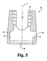
- a stop surface 45 may be included in receiver member 30 in communication with aperture 36. Stop surface 45 is provided to act as a stop for crown assembly 33 (described below). With stop surface 45, crown assembly 33 cannot move upward in aperture 36 beyond a certain position. Further, referring generally to FIG. 5 , a side opening 46 in the side of a specific embodiment of receiver member 49 may be provided to allow insertion of base member 32. Side opening 46 is provided in addition to channel 35, aperture 36 and groove 44, and may be to the side of and transverse to aperture 36 and channel 35. It will be appreciated that side opening 46 could be placed in any part of receiver member 30, such as directly below channel 35. The compressibility or non-compressibility of the base or retaining member-32-to be used may determine the minimum width of side opening 46, as side opening 46 need not be as wide if the base member is compressible.
- Bone anchoring member 31 in one embodiment, is a screw element having a head portion 47 and a shank portion 48.
- Shank portion 48 includes a bone engaging portion 50, which in one particular embodiment has threads, such as for engaging bone tissue, and may also include a non-threaded portion 52.
- At least part of head portion 47 is preferably, but not necessarily, spherical, rounded, conical, or otherwise configured for rotation or angulation with respect to receiver member 30 and base member 32.
- a top part of head portion 47 includes an opening 54 for accepting a tool, e.g. a hexagonal opening, for inserting bone anchoring member 31. It will be understood that an alternative bone anchoring member in the form of a hook element is also contemplated.
- Such a hook includes a head portion identical or similar to head portion 47 of bone anchoring member 31, and a shank portion similar to shank portion 48 of bone anchoring member 31.
- the shank portion of such a hook would include or extend into a curved portion for engaging or connecting to a bone.
- Base or retaining member 32, 132, 232 in the embodiments shown in FIGS. 3 , 4 and 6-9 are similar. Referring generally to base member 32, it is substantially circular in one embodiment with a flange 56 and a center opening 58. Center opening 58 is bounded by walls 60, 61. As examples, walls 60, 61 may be a portion of a cone or sphere, or may form a sharp edge.
- the embodiments of base members 32 and 132 generally form a C-shaped element ( FIGS. 3-4 , 6-7 and 9 ), and the embodiment of base member 232 generally forms the entirety of a circle ( FIG. 8 ).
- Base member 32 includes a gap 62 in its circumference along with a center opening 58.
- Opening 58 is shown in one embodiment as substantially circular, but could also have a conical, spherical, stepped, recessed, and/or other configuration. Opening-58 allows head portion 47 of bone anchoring member 31 to rotate with respect to base member 32, allowing positioning of bone anchoring member 31 at any of a variety of angles with respect to longitudinal axis L ( FIG. 4 ) of receiver member 30.
- the interference of base member 32 and shank portion 48 of bone anchoring member 31 determines a first maximum angle a between bone anchoring member 31 and axis L for at least a portion of the relative positions of bone anchoring member 31 and base member 32.
- Gap 62 acts as a slot or elongation of center opening 58, so that when bone anchoring member 31 is oriented so that shank portion 48 is substantially aligned with gap 62, a second, larger maximum angle 0 between bone anchoring member 31 and axis L is available because interference between shank 48 and base member 32 is either eliminated or moved outward.
- gap 62 provides space in which at least a part of shank portion 48 can extend to provide a greater maximum angle P.
- a wider gap 62 for example a gap 62 that is larger than the diameter of shank portion 48 of bone anchoring member 31, allows shank portion 48 to extend through gap 62, and the maximum angle R in that instance is limited only by interference between shank portion 48 and receiver member 30.
- a narrower gap 62 allows only a part of shank portion 48 into gap 62, and thus the maximum angle (3 is limited by the points of interference between shank portion 48 and the edges of base member 32 adjacent gap 62.
- the magnitude of maximum angle 0 is therefore a function of the width of gap 62.
- center opening 258 also has a circular portion 258a and an elongated or slot portion 258b.
- first maximum angle between bone anchoring member 31 and axis L when bone anchoring member 31 is not substantially aligned with slot portion 258b.
- a second larger maximum angle is available when-bone anchoring member 31 is substantially aligned with at least part of slot portion 258b. Similar to the discussion above with respect to gap 62, it will be seen that the magnitude of that second larger maximum angle is a function of the width and length of slot portion 258b.
- the embodiment of base member 232 in FIG. 8 is shown without one or more flanges. It will be understood that such flange(s) as flange 52 could be provided for this embodiment as well.
- the embodiment of base member 132 ( FIG. 9 ) combines features of base members 32 and 232.
- Base member 132 is essentially the same as base member 232, with the exception that a gap 162 is provided. Gap 162 can further allow base member 132 to be radially compressed, e.g. for insertion into groove 44 of receiver member 30, or to be radially expanded. In embodiments that are to be radially compressed or expanded, e.g. base member 32, 132, one or more notches or indentations 163 ( FIG. 9 ) may be provided around the outer side surface of base member 132.
- three such notches 163 may be provided, one placed substantially diametrically opposite gap 162, and the remaining two notches 163 placed approximately about 90 degrees from either side of the first notch 163, or approximately about equidistant between the first notch 163 and gap 162.
- Such notch(es) 163 provide stress relief for base member 132, reducing or eliminating the risk that base member 132 will not return to its original shape after radial compression or expansion.
- one or more notches similar or identical to notches 163 can be incorporated into other C-shaped embodiments such as base member 32.
- Base members 32, 132, 232 may also be configured with one or more undulating or wavy portions.
- An example of such an undulating ring is seen in FIG. 17 a of U.S. Patent No. 6,485,491 .
- Such undulating portions are preferably sufficiently thin to enable embodiments of base members 32, 132, 232 that include them to elastically flatten. These embodiments can act as a type of spring, exerting a force on the head portion 47 of bone anchoring member 31. Such force may hold head portion 47 against crown assembly 33 (if present), or another part of receiver member 30. Looseness or "slack" in the fastener 22 can thus be reduced or substantially eliminated, without preventing all movement of head portion 47. When fastener 22 is locked as described below, the opposing force on head portion 47 may flatten any undulating portions of a base member 32, 132, 232 partially or completely.
- Crown assembly 33 in the embodiment shown in FIG. 3 , includes at least a crown element 64, which is preferably substantially cylindrical with an internal opening 66 and an undersurface 68. Crown element 64 is sized to fit within aperture 36 of receiver member 30, so that crown element 64 has some freedom of axial movement within aperture 36.
- Internal opening 66 is provided to allow access to tool opening 54 in bone anchoring member 31 when crown element 64 is above or atop bone anchoring member 31.
- Undersurface 68 is preferably configured to accommodate at least a part of head portion 47 of bone anchoring member 31.
- undersurface 68 may be shaped (e.g. spherical, rounded, conical, or otherwise) to allow relative movement between crown element 64 and part or all of head portion 47 of bone anchoring member 31.
- undersurface 68 may have substantially the same diameter as head portion 47.
- crown element 64 may include an external groove 70
- crown assembly 33 may also include a C-shaped snap-ring 72 adapted to fit at least partially within groove 70. Snap-ring 72 assists in base crown element 64 within receiver member 30 by interfering with stop surface 45 in receiving member 30.
- Snap-ring 72 may also be configured with one or more undulating or wavy portions. Such undulating portions are preferably sufficiently thin to enable embodiments of snap-ring 72 that include them to elastically flatten. These embodiments can act as a type of spring between receiver member 30 (e.g. stop surface 45) and crown element 64, exerting a force on the crown element 64. Such force may hold crown element 64 against head portion 47 of bone anchoring member 31 or against a part of receiver member 30 (if bone anchoring member 31 is not yet within receiver member 31). Looseness or "slack" in the fastener 22 can thus be reduced or substantially eliminated, without preventing all movement of crown element 64. When fastener 22 is locked as described below, the forces on crown element 64 may flatten any undulating portions of snap-ring 72 partially or completely.
- Compression member 34 is shown in one embodiment as an externally threaded element.
- Compression member 34 may be a standard set screw or a break-off set screw such as those disclosed in U.S. Patent Nos. 6,478,795 .
- Compression member 34 may also include reverse angle threads as disclosed in U.S. Patent No. 6,296,642 .
- compression member 34 is configured to thread into threaded portion 42 of receiver member 30 and against rod 16, to compress crown element 64 and lock fastener 22 with respect to rod 16.
- compression member 34 can include an external element such as a nut or cap, which may have threads or other features for holding the external element to receiver member 30. If an external element is used, receiver member 30 may be provided with compatible threads or other features for mating with the external element.
- receiver member 330 and base member 332 can be used with the elements described above in a multi-axial fastener similar to fastener 22, or in other orthopedic implants.
- Receiver member 330 is shown with channel 335 and aperture 336. It will be appreciated that in one embodiment receiver member 330 can include structure similar or identical in form and purpose to threaded portion 42 and stop surface 45 described above with respect to receiver member 30.
- Receiver member 330 and base member 332 are rotatably connected, and such rotatable connection can be achieved in a number of ways.
- receiver member 330 includes a groove 344 or thread (not shown). Groove 344 is shown as external of receiver member 330, but it will be understood that such a groove 344 or thread could also be placed inside receiver member 330.
- Base member 332 in this embodiment includes a circumferential flange 352 or threads (not shown) for rotatable connection to receiver member 330. Base member 332 attaches to receiver member 330 by placing flange 352 into groove 344, preferably in a snap- or press-fit.
- flange 352 will extend outwardly from base member 332, or be otherwise configured to fit with groove 344.
- base member 332 depicted in FIG. 10 includes an opening 358 as defined in claim 1 for allowing multi-axial positioning of a bone anchoring member 31.
- This embodiment of base member 332 allows loading of crown element 64 (and snap-ring 72, if used) through lower portion 338 into aperture 336 of receiver member 330.
- Base member 432 includes an opening that permits a larger maximum angle in at least one orientation of the fastener with respect to base member 432 than in other orientations. As shown in FIG. 11 , elongated portion 458b can extend through the side of base member 432, creating a notch 455. Base member 432 can be rotated with respect to receiver member 430 so that elongated portion 458b can be oriented at any of a number of orientations with respect to channel 435 of receiver member 430.
- opening 558 is non-perpendicular to axis L of aperture 536 of receiver member 530.
- first part 574 of opening 558 that is relatively close to receiver member 530 and a diametrically opposed second part 576 of opening 558 that is relatively distant from receiver member 530.
- fastener 31 is oriented so that shank portion 52 is substantially adjacent to first part 574 of opening 558, then the maximum angle of fastener 31 with respect to axis L is greater than a maximum angle afforded by another part of opening 558.
- receiver member 630 and base member 632 could be rotatably connected via a C-shaped snap-ring 637 ( FIG. 13 ).
- receiver member 630 includes a groove 644 in a lower portion
- base member 632 includes a groove 680 in an upper portion.
- Snap-ring 637 is sized to fit at least partially within grooves 644 and 680, so that a portion of snap-ring 637 extends outside of grooves 644 and 680. To assemble, snap-ring 637 may be placed in one of grooves 644 and 680.
- Snap-ring 637 may be expanded or contracted as necessary to allow it and the part to which it is connected (receiver member 630 or base member 632) to be connected to the other part so that snap-ring 637 fits at least partially within the other of grooves 644 and 680. When assembled, snap-ring 637 is within at least a part of each groove 644 and 680, thereby holding receiver member 630 and base member 632 together.
- Base member 632 includes an opening as defined in claim 1.
- receiver member e.g. receiver member 630
- base member e.g. base member 632
- snap-ring e.g. snap-ring 637
- shape-memory alloy such as the nickel-titanium alloy know as Nitinol®.
- receiver member 630 and base member 632 may be rotatable until implanted, when the change in temperature of the alloy causes a press or interference fit between them, or snap-ring 637 could expand or contract with a change in temperature to hold receiver member 630 and base member 632 together and/or non-rotatable.
- a device such as multi-axial fastener 22 may be implanted as follows.
- One or more surgical openings are made proximate to an area of the spine or other bones to be instrumented.
- the surgical openings may be open, minimally-invasive, or of other types that may be known in surgical practice.
- the vertebrae or other surgical site is prepared, for example by abrading tissue, drilling holes, adjusting bony or other tissue, or other steps to prepare and fixate a bone or bones.
- receiver member 30 is multi-axially positionable with respect to bone anchoring member 31, and base member 32 or 232 is rotatable with respect to receiver member 30 so that the elongated or slot portion of opening 58 can point in any direction with respect to receiver member 30.
- Base member 32 or 232 can be intentionally pre-oriented with respect to receiver member 30 by the assembler prior to surgery, or can simply be placed in groove 44 of receiver member 30 in any orientation.
- the surgeon is able to change the relative orientation of receiver member 30 with respect to base member 32 or 232 and/or bone anchoring member 31 immediately prior to surgery by rotating bone anchoring member 31 with respect to receiver member 30 and/or base member 32, or by rotating receiver member 30 with respect to base member 32, or both.
- the surgeon is also able to change those relative orientations during surgery, as further described below.
- Crown assembly 33 (if present) is held within receiver member 30 between head 47 of fastening member 31 and stop surface 45. It will be appreciated that assembly of these parts can take place at any time prior to insertion, by the surgeon or other person, and that kits including one or more of each type of part described above, in one or more sizes can be provided for the user's convenience.
- bone anchoring member 31 is a screw
- threaded shank portion 50 may be inserted into a prepared hole in a vertebra.
- bone anchoring member 31 includes a self-drilling screw or a self-tapping screw
- a previously-drilled hole in the bone, or tapping of the hole with a separate tool may not be necessary.
- An appropriate tool may be inserted through aperture 36 of receiver member 30 and opening 66 of crown member 64 into tool opening 54 of bone anchoring member 31, and then such tool may be used to turn bone anchoring member 31 to insert it in the bone.
- bone anchoring member 31 When bone anchoring member 31 is inserted into the bone to the desired depth, the tool is removed, and the surgeon can make adjustments to the orientation of receiver member 30 with respect to bone anchoring member 31 or to the orientation of base member 32 with respect to receiver member 30. For example, the surgeon can turn or angle receiver member 30 with respect to bone anchoring member 31. The surgeon can also turn base member 32 in groove 44 with respect to receiver member 30, for instance by maneuvering receiver member 30 and base member 32 together until a part of bone anchoring member 31 is within an elongated opening in base member 32 such as gap 62, and then turning receiving member 30 with respect to bone anchoring member. Bone anchoring member 31 interferes with base member 32 at gap 62 so that base member 32 cannot turn with receiver member 30.
- the orientation of the elongated part of center opening 58 of base member 32 rotates or pivots, so that the direction in which bone anchoring member 31 can attain the largest maximum angulation with respect to receiver member 30 is pivotable and independent of the orientation of receiver member 30.
- Other implant devices such as additional fasteners 22, multi-axial screws 23, 24, and/or monoaxial hooks 29, can similarly be inserted into the same or other bones.
- a longitudinal member, such as spinal rod 16 or 17, can be bent or otherwise contoured and then inserted into the surgical site. The longitudinal member is connected to receiver member 30 by insertion of a portion of it into channel 35 of receiver member 30.
- the longitudinal member is inserted (or “reduced") at least to a point so that compression member 34 can be connected to receiver member 30 and hold the longitudinal member within channel 35. Similar longitudinal member reduction can be done with respect to other screws, hooks, connectors, clamps or other devices.
- the surgeon can then manipulate the spine and the implanted devices so that the spine is corrected or placed in a therapeutically improved position.
- the longitudinal member is locked within receiver member 30 by tightening compression member 34 against the longitudinal member, which presses against crown assembly 33 (if present), fastener member head portion 47, and base member 32.
- Receiver member 30, particularly channel 35 and its adjoining surfaces, as well as rod 16 or 17 and/or bone anchoring member 31 can be configured so that crown element 64 or crown assembly 33 is not necessary.
- Other implant devices are similarly tightened to hold the longitudinal member, and the spine, in the desired position.
- one or more spacing devices can be inserted between adjacent vertebrae.
- intervertebral implant devices are disclosed in U.S. Patent Nos. 5,984,967 and 6,113,637 .
- "Cage"-type intervertebral implants may also be packed or otherwise provided with one or more substances for inducing or promoting bone growth, such as a bone morphogenic protein, as disclosed in U.S. Patent No. 5,984,967 .
- FIG. 14 there is shown a possible embodiment of a fastener 22 connected to a rod 16 as part of a system (such as one of the embodiments of system 15 shown in FIGS.
- FIG. 14 shows the implants placed anteriorly on the spinal column, it is understood that they can be placed posteriorly or in any other appropriate or necessary position.
- an implant system 715 featuring implants such as those disclosed herein Bone growth-promoting substance 720, such as BMP (bone morphogenic protein), LMP (LIM mineralization protein), bone chips or marrow or other natural tissue, DBM (demineralized bone matrix), or mesenchymal stem cells, along with any necessary or appropriate carriers or other therapeutic composition, is packed in and/or around the implants and vertebrae.
- BMP bone morphogenic protein
- LMP LIM mineralization protein
- DBM demineralized bone matrix
- mesenchymal stem cells along with any necessary or appropriate carriers or other therapeutic composition
- a system 15 can include a set of two rods 16, 17 attached to separate parts of a bone or spinal column.
- one rod 16 can be attached to a set of vertebrae on one side, and a second rod 16 can be attached to another side of the same vertebrae.
- These rods can then be connected, for example with cross connector 25.
- additional smaller rods 17 can be connected via longitudinal connectors 27 to rods 16, and can be fixed to vertebrae (e.g. cervical vertebrae) above the level of the vertebrae to which rods 16 are fixed. It will be appreciated that such longitudinal connection of rods can be accomplished along any contiguous segments of the spinal column, whether cervical, thoracic, lumbar or sacral.
- the structures described above are preferably made of biocompatible materials such as stainless steel, titanium, nickel-titanium (e.g. Nitinol®) or other shape-memory alloys, certain hard plastics or other synthetic materials, and the like.
- biocompatible materials such as stainless steel, titanium, nickel-titanium (e.g. Nitinol®) or other shape-memory alloys, certain hard plastics or other synthetic materials, and the like.
Description
- The disclosed subject matter generally relates to implants used for correction of orthopedic injuries or deformities, and more specifically, but not exclusively, concerns apparatuses for fixing a portion of the spine to allow correction or healing thereof.
- In the realm of neurologic, orthopedic and spinal surgery, it is well known to use implants to fix the position of bones. In this way, the healing of a broken bone can be promoted, and malformations or other injuries can be corrected. For example, in the field of spinal surgery, it is well known to place such implants into vertebrae for a number of reasons, including (a) to correct an abnormal curvature of the spine, including a scoliotic curvature, (b) to maintain appropriate spacing and provide support to broken or otherwise injured vertebrae, and (c) to perform other therapies on the spinal column.
- Typical implant systems include several pieces, which may be associated or useful with only specific other pieces. Among such pieces are screws, hooks rods, plates and similar longitudinal members for supporting, holding and/or correcting one or more bones. Such longitudinal members can be fastened to bones via direct or indirect connection to hooks, screws, bolts or other fasteners, and can be linked to each other by a variety of connectors. In the spinal field, for example, screws or other fasteners can be attached to two or more vertebrae, the vertebrae can be adjusted into their normal or a therapeutically better position, and longitudinal members are connected to the fasteners so that the vertebrae are held in the normal ortherapeutically improved position. Interbody devices, such as intervertebral cages or spacers to maintain the space and positioning of two adjacent vertebrae with respect to each other are also known.
- Accordingly, known bone screws, hooks, clamps and other bone fasteners or fixation devices can be connected or adjoined to a particular bone or bones as a connection between the remainder of the implant and the bone(s).
- Specially formed plates or rods are commonly used as stabilization and support members. Thus, in a common spinal implant system, a spinal plate is implanted along one or more vertebrae by driving a bone screw through the plate and into each of two vertebrae. The vertebrae are thus supported and kept in a particular -position by the plate, so as to promote correction or healing.
- Where a rod is used as a support and stabilizing member, commonly a series of two or more screws are inserted into two or more vertebrae to be instrumented. A rod is then placed within or coupled to the heads of the screws, or is placed within a connecting device that links the rod and a screw head, and the connections are tightened. In this way, a rigid supporting structure is fixed to the vertebrae, with the rod providing the support that maintains and/or promotes correction of the vertebral malformation or injury.
- Many varieties of bone fixation devices (e.g. screws and hooks) are monoaxial in construction. That is, such devices are connected to the rod or plate such that a longitudinal axis through the rod or plate and a longitudinal axis through the fixation device are capable of only a single position with respect to each other. While useful in certain circumstances, in some therapeutic situations such an inflexible device is impractical, or can lead to a longer duration of surgery.
- More recently, bone fixation devices having multi-axial capability have been introduced. Examples of such constructs are shown in
U.S. Pat. Nos. 5,797,911 ,5,954,725 , and6,280,445 . These devices allow one or more degrees of freedom between a fastening portion or fastening member and a receiving portion or member, reducing the required precision of placement of the fixation device, since a head portion of the fixation device is multi-axially positionable around the bone-threaded or hook portion. The head can thus be positioned so as to easily receive the rod, limiting or removing much of the positioning difficulty inherent in prior device. However, such devices provide a single maximum angle between the fastening portion and the receiving portion for every relative orientation of those parts. Other devices have made possible a larger maximum angle between the fastening portion and the receiving portion when the fastening portion occupies one position with respect to the receiving portion, but allow only a smaller maximum angle when the fastening portion occupies any other position with respect to the fastening portion. -
US2002/0058942 andUS 2003/0055426 describe bone fixation systems according to the preamble ofclaim 1. - The invention is defined in the appended claims.
- The disclosure includes a bone fixation system including a receiver member having a longitudinal axis, a bone anchoring member having a head portion and a bone-engaging portion, the bone anchoring member having at least a first maximum angular position and a second maximum angular position relative to the axis, wherein the second maximum angular position includes a greater angle relative to the axis than the first maximum angular position, and a base member rotatably connected to the receiver member, the base member having at least one wall defining an opening that limits the bone anchoring member to occupy either of the first maximum angular position and the second maximum angular position. The system may also include an elongated member connected to the receiver member.
-
-
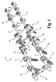
FIG. 1 is a perspective view of an orthopedic implant system according to one embodiment of the present invention. -
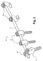
FIG. 2 is a perspective view of a portion of an orthopedic implant system similar to the embodiment ofFIG. 1 . -
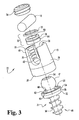
FIG. 3 is an exploded view of an orthopedic implant according to one embodiment of the present invention. -
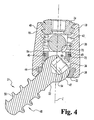
FIG. 4 is a side cross-sectional view of the assembled embodiment of the orthopedic implant shown inFIG. 3 . -
FIG. 5 is a side cross-sectional view of another embodiment of -a receiver member useful with the embodiment of the orthopedic implant shown inFIG. 3 . -
FIG. 6 is a top view of aspects of the embodiment of the orthopedic implant shown inFIG. 3 . -
FIG. 7 is a side view of the aspects of the embodiment of the orthopedic implant shown inFIG. 6A . -
FIG. 8 is a perspective view of an embodiment of a base or retaining member useable with the embodiment of an orthopedic implant shown inFIG. 3 . -
FIG. 9 is a perspective view of another embodiment of a base or retaining member useable with the embodiment of an orthopedic implant shown inFIG. 3 . -
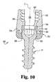
FIG. 10 is a side cross-sectional, view of an orthopedic implant according to another embodiment of the present invention. -
FIG. 11 is a side cross-sectional view of an orthopedic implant according to yet another embodiment of the present invention. -
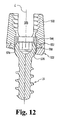
FIG. 12 is a side cross-sectional view of an orthopedic implant according to still another embodiment of the present invention. -
FIG. 13 is a side cross-sectional view of an orthopedic implant according to still another embodiment of the present invention. -
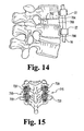
FIG. 14 is a side view of a portion of an orthopedic implant system attached to a part of a spinal column. -
FIG. 15 is a front view of a portion of an orthopedic implant system attached to a part of a spinal column. - For the purpose of promoting an understanding of the principles of the invention, reference will now be made to the embodiments illustrated in the drawings and specific language will be used to describe the same. It will nevertheless be understood that no limitation of the scope of the invention is thereby intended, such alterations and further modifications in the illustrated device, and such further applications of the principles of the invention as illustrated therein, being contemplated as would normally occur to one skilled in the art to which the invention relates.
- Referring generally to
FIGS. 1-2 , embodiments of asystem 15 for orthopedic implantation are shown. Among the possible implants that can be a part ofsystem 15 are longitudinal members such asrods screws cross connectors 25, 26,longitudinal connector 27,lateral connector 28,hooks 29, and other devices. It will be understood that other types of fasteners or connectors (e.g. clamps) can be used in connection withsystem 15 or other aspects of the present disclosure. Further additional or alternative longitudinal members can also be used, such as the plates or rods disclosed inU.S. Patent No. 6,485,491 , or the rods disclosed inU.S. Patent No. 5,217,461 . - As will be described further below, the illustrated embodiments of
system 15 can be implanted via an open, minimally-invasive or other surgical approach. Generally, fasteners are inserted into one or more bones, longitudinal members are contoured, if necessary, and surgically inserted and connected to the fasteners. The relative angles of fasteners with respect to the longitudinal member can be adjusted as necessary for ease of connection of the longitudinal member to the fasteners. Connectors are fitted to longitudinal members and/or fasteners as necessary or desired, and all elements are locked against movement with respect to other parts. - Referring now generally to
FIGS. 3-4 , there is shown an embodiment ofmulti-axial fastener 22. Fastener 22 includes areceiver member 30, abone anchoring member 31, a base or retainingmember 32, a crown assembly 33, and acompression member 34.Receiver member 30 has achannel 35 therethrough adapted to accommodaterod 16 or other longitudinal member. Anaperture 36, which may be cylindrical, extends from alower portion 38 ofreceiver member 30 transversely to and in communication withchannel 35. In a specific embodiment,aperture 36 extends from thelower portion 38 to atop portion 40 ofreceiver member 30, andaperture 36 has a threadedportion 42 at or neartop portion 40 for use whencompression member 34 is or includes a set screw or other element with external threads. Threadedportion 42 could be outside ofreceiver member 30 if an external compression member is used. Alternatiavely,receiver member 30 could be externally and/or internally configured for compression members using snapping, twisting or other types of closures. Thelower portion 38 ofreceiver member 30 has agroove 44. In the illustrated embodiment,groove 44 extends around the entire circumference ofaperture 36. - The illustrated embodiment of
receiver member 30 offastener 22 is an "open backed" variety. That is,channel 35 is open through the top ofreceiver member 30, makingreceiver member 30 generally U-shaped and defining twobranches U.S. Patent No. 5,005,562 . - A
stop surface 45 may be included inreceiver member 30 in communication withaperture 36. Stopsurface 45 is provided to act as a stop for crown assembly 33 (described below). Withstop surface 45, crown assembly 33 cannot move upward inaperture 36 beyond a certain position. Further, referring generally toFIG. 5 , aside opening 46 in the side of a specific embodiment ofreceiver member 49 may be provided to allow insertion ofbase member 32.Side opening 46 is provided in addition tochannel 35,aperture 36 andgroove 44, and may be to the side of and transverse toaperture 36 andchannel 35. It will be appreciated thatside opening 46 could be placed in any part ofreceiver member 30, such as directly belowchannel 35. The compressibility or non-compressibility of the base or retaining member-32-to be used may determine the minimum width ofside opening 46, as side opening 46 need not be as wide if the base member is compressible. -
Bone anchoring member 31, in one embodiment, is a screw element having ahead portion 47 and ashank portion 48.Shank portion 48 includes abone engaging portion 50, which in one particular embodiment has threads, such as for engaging bone tissue, and may also include anon-threaded portion 52. At least part ofhead portion 47 is preferably, but not necessarily, spherical, rounded, conical, or otherwise configured for rotation or angulation with respect toreceiver member 30 andbase member 32. A top part ofhead portion 47 includes anopening 54 for accepting a tool, e.g. a hexagonal opening, for insertingbone anchoring member 31. It will be understood that an alternative bone anchoring member in the form of a hook element is also contemplated. Such a hook includes a head portion identical or similar tohead portion 47 ofbone anchoring member 31, and a shank portion similar toshank portion 48 ofbone anchoring member 31. The shank portion of such a hook would include or extend into a curved portion for engaging or connecting to a bone. - Base or retaining
member FIGS. 3 ,4 and6-9 are similar. Referring generally tobase member 32, it is substantially circular in one embodiment with aflange 56 and acenter opening 58.Center opening 58 is bounded bywalls walls base members FIGS. 3-4 ,6-7 and9 ), and the embodiment ofbase member 232 generally forms the entirety of a circle (FIG. 8 ).Base member 32 includes agap 62 in its circumference along with acenter opening 58.Opening 58 is shown in one embodiment as substantially circular, but could also have a conical, spherical, stepped, recessed, and/or other configuration. Opening-58 allowshead portion 47 ofbone anchoring member 31 to rotate with respect tobase member 32, allowing positioning ofbone anchoring member 31 at any of a variety of angles with respect to longitudinal axis L (FIG. 4 ) ofreceiver member 30. - Referring to
FIG. 7 , it will be noted that the interference ofbase member 32 andshank portion 48 ofbone anchoring member 31 determines a first maximum angle a betweenbone anchoring member 31 and axis L for at least a portion of the relative positions ofbone anchoring member 31 andbase member 32.Gap 62 acts as a slot or elongation ofcenter opening 58, so that whenbone anchoring member 31 is oriented so thatshank portion 48 is substantially aligned withgap 62, a second, larger maximum angle 0 betweenbone anchoring member 31 and axis L is available because interference betweenshank 48 andbase member 32 is either eliminated or moved outward. In other words,gap 62 provides space in which at least a part ofshank portion 48 can extend to provide a greater maximum angle P. Awider gap 62, for example agap 62 that is larger than the diameter ofshank portion 48 ofbone anchoring member 31, allowsshank portion 48 to extend throughgap 62, and the maximum angle R in that instance is limited only by interference betweenshank portion 48 andreceiver member 30. Anarrower gap 62 allows only a part ofshank portion 48 intogap 62, and thus the maximum angle (3 is limited by the points of interference betweenshank portion 48 and the edges ofbase member 32adjacent gap 62. The magnitude of maximum angle 0 is therefore a function of the width ofgap 62. - In the solid-circumference embodiment of base member 232 (
FIG. 8 ), center opening 258 also has acircular portion 258a and an elongated orslot portion 258b. Whenbone anchoring member 31 is used withbase member 232, there is a first maximum angle betweenbone anchoring member 31 and axis L whenbone anchoring member 31 is not substantially aligned withslot portion 258b. A second larger maximum angle is available when-bone anchoring member 31 is substantially aligned with at least part ofslot portion 258b. Similar to the discussion above with respect togap 62, it will be seen that the magnitude of that second larger maximum angle is a function of the width and length ofslot portion 258b. The embodiment ofbase member 232 inFIG. 8 is shown without one or more flanges. It will be understood that such flange(s) asflange 52 could be provided for this embodiment as well. The embodiment of base member 132 (FIG. 9 ) combines features ofbase members -
Base member 132 is essentially the same asbase member 232, with the exception that a gap 162 is provided. Gap 162 can further allowbase member 132 to be radially compressed, e.g. for insertion intogroove 44 ofreceiver member 30, or to be radially expanded. In embodiments that are to be radially compressed or expanded,e.g. base member FIG. 9 ) may be provided around the outer side surface ofbase member 132. In a particular embodiment, threesuch notches 163 may be provided, one placed substantially diametrically opposite gap 162, and the remaining twonotches 163 placed approximately about 90 degrees from either side of thefirst notch 163, or approximately about equidistant between thefirst notch 163 and gap 162. Such notch(es) 163 provide stress relief forbase member 132, reducing or eliminating the risk thatbase member 132 will not return to its original shape after radial compression or expansion. It will be noted that one or more notches similar or identical tonotches 163 can be incorporated into other C-shaped embodiments such asbase member 32. -
Base members U.S. Patent No. 6,485,491 . Such undulating portions are preferably sufficiently thin to enable embodiments ofbase members head portion 47 ofbone anchoring member 31. Such force may holdhead portion 47 against crown assembly 33 (if present), or another part ofreceiver member 30. Looseness or "slack" in thefastener 22 can thus be reduced or substantially eliminated, without preventing all movement ofhead portion 47. Whenfastener 22 is locked as described below, the opposing force onhead portion 47 may flatten any undulating portions of abase member - Crown assembly 33, in the embodiment shown in
FIG. 3 , includes at least acrown element 64, which is preferably substantially cylindrical with aninternal opening 66 and anundersurface 68.Crown element 64 is sized to fit withinaperture 36 ofreceiver member 30, so thatcrown element 64 has some freedom of axial movement withinaperture 36.Internal opening 66 is provided to allow access totool opening 54 inbone anchoring member 31 whencrown element 64 is above or atopbone anchoring member 31.Undersurface 68 is preferably configured to accommodate at least a part ofhead portion 47 ofbone anchoring member 31. For example,undersurface 68 may be shaped (e.g. spherical, rounded, conical, or otherwise) to allow relative movement betweencrown element 64 and part or all ofhead portion 47 ofbone anchoring member 31. In the embodiment in which both undersurface 68 andhead portion 47 have a rounded or spherical portion,undersurface 68 may have substantially the same diameter ashead portion 47. Further,crown element 64 may include anexternal groove 70, and crown assembly 33 may also include a C-shaped snap-ring 72 adapted to fit at least partially withingroove 70. Snap-ring 72 assists inbase crown element 64 withinreceiver member 30 by interfering withstop surface 45 in receivingmember 30. - Snap-
ring 72 may also be configured with one or more undulating or wavy portions. Such undulating portions are preferably sufficiently thin to enable embodiments of snap-ring 72 that include them to elastically flatten. These embodiments can act as a type of spring between receiver member 30 (e.g. stop surface 45) andcrown element 64, exerting a force on thecrown element 64. Such force may holdcrown element 64 againsthead portion 47 ofbone anchoring member 31 or against a part of receiver member 30 (ifbone anchoring member 31 is not yet within receiver member 31). Looseness or "slack" in thefastener 22 can thus be reduced or substantially eliminated, without preventing all movement ofcrown element 64. Whenfastener 22 is locked as described below, the forces oncrown element 64 may flatten any undulating portions of snap-ring 72 partially or completely. -
Compression member 34 is shown in one embodiment as an externally threaded element.Compression member 34 may be a standard set screw or a break-off set screw such as those disclosed inU.S. Patent Nos. 6,478,795 .Compression member 34 may also include reverse angle threads as disclosed inU.S. Patent No. 6,296,642 . In the threaded embodiment,compression member 34 is configured to thread into threadedportion 42 ofreceiver member 30 and againstrod 16, to compresscrown element 64 andlock fastener 22 with respect torod 16. Alternatively or additionally,compression member 34 can include an external element such as a nut or cap, which may have threads or other features for holding the external element toreceiver member 30. If an external element is used,receiver member 30 may be provided with compatible threads or other features for mating with the external element. - Alternative embodiments of a receiver member and a base member are depicted in
FIGS. 10-12 . Throughout this disclosure, related features are indicated by replacing or adding a new first digit to the numbers identified above. Referring toFIG. 10 ,receiver member 330 andbase member 332 can be used with the elements described above in a multi-axial fastener similar tofastener 22, or in other orthopedic implants.Receiver member 330 is shown withchannel 335 andaperture 336. It will be appreciated that in oneembodiment receiver member 330 can include structure similar or identical in form and purpose to threadedportion 42 and stopsurface 45 described above with respect toreceiver member 30. -
Receiver member 330 andbase member 332 are rotatably connected, and such rotatable connection can be achieved in a number of ways. In one embodiment,receiver member 330 includes a groove 344 or thread (not shown). Groove 344 is shown as external ofreceiver member 330, but it will be understood that such a groove 344 or thread could also be placed insidereceiver member 330.Base member 332 in this embodiment includes acircumferential flange 352 or threads (not shown) for rotatable connection toreceiver member 330.Base member 332 attaches toreceiver member 330 by placingflange 352 into groove 344, preferably in a snap- or press-fit. Where threads are provided onbase member 332 andreceiver member 330, those threads are engaged to rotatably connectbase member 332 andreceiver member 330. In the embodiment in which groove 344 is insidereceiver member 330,flange 352 will extend outwardly frombase member 332, or be otherwise configured to fit with groove 344. - The embodiment of
base member 332 depicted inFIG. 10 includes anopening 358 as defined inclaim 1 for allowing multi-axial positioning of abone anchoring member 31. This embodiment ofbase member 332 allows loading of crown element 64 (and snap-ring 72, if used) throughlower portion 338 intoaperture 336 ofreceiver member 330. -
Base member 432 includes an opening that permits a larger maximum angle in at least one orientation of the fastener with respect tobase member 432 than in other orientations. As shown inFIG. 11 ,elongated portion 458b can extend through the side ofbase member 432, creating anotch 455.Base member 432 can be rotated with respect toreceiver member 430 so thatelongated portion 458b can be oriented at any of a number of orientations with respect to channel 435 ofreceiver member 430. - In another embodiment (
FIG. 12 ), opening 558 is non-perpendicular to axis L of aperture 536 ofreceiver member 530. In this case, there will be afirst part 574 of opening 558 that is relatively close toreceiver member 530 and a diametrically opposedsecond part 576 of opening 558 that is relatively distant fromreceiver member 530. Whenfastener 31 is oriented so thatshank portion 52 is substantially adjacent tofirst part 574 ofopening 558, then the maximum angle offastener 31 with respect to axis L is greater than a maximum angle afforded by another part ofopening 558. - Alternatively, the rotatable connection of a receiver member and a base member could be achieved by different structure. For example,
receiver member 630 andbase member 632 could be rotatably connected via a C-shaped snap-ring 637 (FIG. 13 ). In this embodiment,receiver member 630 includes agroove 644 in a lower portion, andbase member 632 includes agroove 680 in an upper portion. Snap-ring 637 is sized to fit at least partially withingrooves ring 637 extends outside ofgrooves ring 637 may be placed in one ofgrooves ring 637 may be expanded or contracted as necessary to allow it and the part to which it is connected (receiver member 630 or base member 632) to be connected to the other part so that snap-ring 637 fits at least partially within the other ofgrooves ring 637 is within at least a part of eachgroove receiver member 630 andbase member 632 together.Base member 632 includes an opening as defined inclaim 1. - Any embodiment of receiver member (e.g. receiver member 630), base member (e.g. base member 632), and/or snap-ring (e.g. snap-ring 637) could be at least partially formed of a shape-memory alloy, such as the nickel-titanium alloy know as Nitinol®. In the embodiment shown in
FIG. 13 , for example,receiver member 630 andbase member 632 may be rotatable until implanted, when the change in temperature of the alloy causes a press or interference fit between them, or snap-ring 637 could expand or contract with a change in temperature to holdreceiver member 630 andbase member 632 together and/or non-rotatable. - In use, a device such as
multi-axial fastener 22 may be implanted as follows. One or more surgical openings are made proximate to an area of the spine or other bones to be instrumented. The surgical openings may be open, minimally-invasive, or of other types that may be known in surgical practice. The vertebrae or other surgical site is prepared, for example by abrading tissue, drilling holes, adjusting bony or other tissue, or other steps to prepare and fixate a bone or bones. - Preferably, prior to insertion of
fastener 22,receiver member 30,bone anchoring member 31,base member receiver member 30 is multi-axially positionable with respect tobone anchoring member 31, andbase member receiver member 30 so that the elongated or slot portion of opening 58 can point in any direction with respect toreceiver member 30.Base member receiver member 30 by the assembler prior to surgery, or can simply be placed ingroove 44 ofreceiver member 30 in any orientation. The surgeon is able to change the relative orientation ofreceiver member 30 with respect tobase member bone anchoring member 31 immediately prior to surgery by rotatingbone anchoring member 31 with respect toreceiver member 30 and/orbase member 32, or by rotatingreceiver member 30 with respect tobase member 32, or both. The surgeon is also able to change those relative orientations during surgery, as further described below. Crown assembly 33 (if present) is held withinreceiver member 30 betweenhead 47 of fasteningmember 31 and stopsurface 45. It will be appreciated that assembly of these parts can take place at any time prior to insertion, by the surgeon or other person, and that kits including one or more of each type of part described above, in one or more sizes can be provided for the user's convenience. - Once the surgical site is prepared, the assembled implant is inserted into the site and placed. In the embodiment in which
bone anchoring member 31 is a screw, threadedshank portion 50 may be inserted into a prepared hole in a vertebra. Wherebone anchoring member 31 includes a self-drilling screw or a self-tapping screw, a previously-drilled hole in the bone, or tapping of the hole with a separate tool, may not be necessary. An appropriate tool may be inserted throughaperture 36 ofreceiver member 30 andopening 66 ofcrown member 64 into tool opening 54 ofbone anchoring member 31, and then such tool may be used to turnbone anchoring member 31 to insert it in the bone. - When
bone anchoring member 31 is inserted into the bone to the desired depth, the tool is removed, and the surgeon can make adjustments to the orientation ofreceiver member 30 with respect tobone anchoring member 31 or to the orientation ofbase member 32 with respect toreceiver member 30. For example, the surgeon can turn orangle receiver member 30 with respect tobone anchoring member 31. The surgeon can also turnbase member 32 ingroove 44 with respect toreceiver member 30, for instance by maneuveringreceiver member 30 andbase member 32 together until a part ofbone anchoring member 31 is within an elongated opening inbase member 32 such asgap 62, and then turning receivingmember 30 with respect to bone anchoring member.Bone anchoring member 31 interferes withbase member 32 atgap 62 so thatbase member 32 cannot turn withreceiver member 30. By turningbase member 32 with respect toreceiver member 30, the orientation of the elongated part of center opening 58 of base member 32 (e.g. gap 62 orslot 158b) rotates or pivots, so that the direction in whichbone anchoring member 31 can attain the largest maximum angulation with respect toreceiver member 30 is pivotable and independent of the orientation ofreceiver member 30. Other implant devices, such asadditional fasteners 22,multi-axial screws spinal rod receiver member 30 by insertion of a portion of it intochannel 35 ofreceiver member 30. The longitudinal member is inserted (or "reduced") at least to a point so thatcompression member 34 can be connected toreceiver member 30 and hold the longitudinal member withinchannel 35. Similar longitudinal member reduction can be done with respect to other screws, hooks, connectors, clamps or other devices. The surgeon can then manipulate the spine and the implanted devices so that the spine is corrected or placed in a therapeutically improved position. When the spine and implants are positioned as the surgeon desires, the longitudinal member is locked withinreceiver member 30 by tighteningcompression member 34 against the longitudinal member, which presses against crown assembly 33 (if present), fastenermember head portion 47, andbase member 32.Receiver member 30, particularlychannel 35 and its adjoining surfaces, as well asrod bone anchoring member 31 can be configured so thatcrown element 64 or crown assembly 33 is not necessary. Other implant devices are similarly tightened to hold the longitudinal member, and the spine, in the desired position. - As a part of the process of adjusting the position of the spinal column, one or more spacing devices can be inserted between adjacent vertebrae. Examples of such intervertebral implant devices are disclosed in
U.S. Patent Nos. 5,984,967 and6,113,637 . "Cage"-type intervertebral implants may also be packed or otherwise provided with one or more substances for inducing or promoting bone growth, such as a bone morphogenic protein, as disclosed inU.S. Patent No. 5,984,967 . Referring toFIG. 14 , there is shown a possible embodiment of afastener 22 connected to arod 16 as part of a system (such as one of the embodiments ofsystem 15 shown inFIGS. 1 or2 ), as well as aintervertebral implant 700 placed in theintervertebral disk space 702 between twovertebrae 704, 706. AlthoughFIG. 14 shows the implants placed anteriorly on the spinal column, it is understood that they can be placed posteriorly or in any other appropriate or necessary position. Referring toFIG. 15 , there is shown animplant system 715 featuring implants such as those disclosed herein Bone growth-promotingsubstance 720, such as BMP (bone morphogenic protein), LMP (LIM mineralization protein), bone chips or marrow or other natural tissue, DBM (demineralized bone matrix), or mesenchymal stem cells, along with any necessary or appropriate carriers or other therapeutic composition, is packed in and/or around the implants and vertebrae. - As seen in
FIG. 1 , asystem 15 can include a set of tworods rod 16 can be attached to a set of vertebrae on one side, and asecond rod 16 can be attached to another side of the same vertebrae. These rods can then be connected, for example with cross connector 25. Further, additionalsmaller rods 17 can be connected vialongitudinal connectors 27 torods 16, and can be fixed to vertebrae (e.g. cervical vertebrae) above the level of the vertebrae to whichrods 16 are fixed. It will be appreciated that such longitudinal connection of rods can be accomplished along any contiguous segments of the spinal column, whether cervical, thoracic, lumbar or sacral. It will further be appreciated that, in place of such longitudinal connection of larger and smaller rods, a single rod having a portion with a smaller diameter and a portion with a larger diameter can be used. Such a rod is disclosed inU.S. Patent No. 5,217,461 . - The structures described above are preferably made of biocompatible materials such as stainless steel, titanium, nickel-titanium (e.g. Nitinol®) or other shape-memory alloys, certain hard plastics or other synthetic materials, and the like.
- While the invention has been illustrated and described in detail in the drawings and foregoing description, the same is to be considered as illustrative and not restrictive in character. It should be understood that only the preferred embodiments have been shown and described and that all changes and modifications that come within the scope of the invention as defined in the appended claims are desired to be protected.
Claims (26)
- A bone fixation system, comprising:a receiver member (330) having a longitudinal axis;a bone anchoring member (31) having a head portion (47) and a bone-engaging portion (50), said bone anchoring member having at least a first maximum angular position and a second maximum angular position relative to said axis, wherein said second maximum angular position includes a greater angle relative to said axis than said first maximum angular position; anda base member (332) rotatably connected to said receiver member (330) about said longitudinal axis to said bone anchoring member (31), said base member having at least one wall defining an opening (358) characterised in that
said opening (358) limits said bone anchoring member (31) to occupy either of said first maximum angular position and said second maximum angular position. - The system of claim 1, wherein at least one of said receiver member (330) and said base member (332) is at least partially made of a shape-memory alloy.
- The system of claim 1 wherein
said receiver member has at least one wall defining a channel (335) for receiving at least a portion of an elongated body. - The system of claim 1 or claim 3, wherein said base member opening has at least a first sized portion corresponding to the first maximum angular position and a second sized portion corresponding to the second maximum angular position.
- The system of claim 1 or claim 3, wherein said base member connects to said receiver member so that at least part of said base member is within said receiver member.
- The system of claim 4, wherein said first sized portion of said base member opening includes a first opening or a substantially circular portion, and said second sized portion of said base member opening includes an elongated portion.
- The system of claim 6, wherein said base member is substantially in the form of a C-shaped member defining a gap, and said gap forms at least part of said elongated portion of said second sized portion of said base member opening.
- The system of claim 6, wherein said base member is substantially in the form of a continuous circumference washer member.
- The system of claim 5, wherein said receiver member includes a bottom surface having an aperture, and said base member is insertable into said receiver member through said aperture.
- The system of claim 9, wherein said receiver member includes at least one groove communicating with said aperture, and said base member includes at least one flange, and wherein said base member and said receiver member are rotatably connected by inserting said at least one flange into said at least one groove.
- The system of claim 5, wherein said receiver member includes a side surface having an aperture, and said base member is insertable into said receiver member through said aperture.
- The system of claim 11, wherein said receiver member includes at least one groove communicating with said aperture, and said base member includes at least one flange, and wherein said base member and said receiver member are rotatably connected by inserting said at least one flange into said at least one groove.
- The system of claim 1 or claim 3, wherein said base member connects to said receiver member so that at least part of said base member is external of said receiver member.
- The system of claim 13, wherein said receiver member has at least one exterior portion with a first groove, and said base member has at least one interior portion with a second groove, and further comprising a ring member adapted to occupy at least a portion of said first and second grooves.
- The system of claim 13, wherein said receiver member has at least one exterior portion with a groove, and said base member has at least one flange, and wherein said base member and said receiver member are rotatably connected by inserting said at least one flange into said at least one groove.
- The system of claim 13, wherein said receiver member has at least one exterior portion with a thread, and said base member has a threaded portion, and wherein said base member and said receiver member are rotatably connected by connecting their respective threaded portions.
- The system of claim 4, wherein said base member has a side surface, and said second sized portion of said base member opening extends to said side surface and forms a notch in said side surface.
- The system of claim 3, wherein said receiver member has a longitudinal axis, and said base member opening is in a plane that is non-perpendicular to said axis so that different parts of said base member opening are different distances from said channel.
- The system of claim 1 or claim 3 further comprising one or more implants from the group consisting of cross connectors, lateral connectors, monoaxial bone anchoring members, multi-axial bone anchoring members, plate members, and occipital fixators.
- The system of claim 3, wherein said elongated body is a spinal rod.
- The system of claim 20, wherein said elongated body is a spinal rod having a substantially constant diameter.
- The system of claim 20, wherein said elongated body is a spinal rod having a first portion with a first substantially constant diameter and a second portion with a second substantially constant diameter that is larger than said first diameter.
- An orthopedic implant apparatus comprising the bone fixation system of claim 3 wherein
said base member permits multi-axial positioning of said bone anchoring member with respect to said receiver member,
said base member and said bone anchoring member having a first relative position wherein the maximum angle between said bone anchoring member and said axis is a first value, and wherein other relative positions of said base member and said bone anchoring member allow a maximum angle between said bone anchoring member and said axis that is less than said first value,
and said first relative position is independent of the orientation of said channel of said receiver member. - The apparatus of claim 23, wherein said receiver member (330) has a side wall with an opening adapted to enable insertion of said base member therethrough.
- The apparatus of claim 23, wherein said base member (332) has a-lower surface that is non-perpendicular to said axis when said base member is connected to said receiver member.
- The apparatus of claim 23, wherein said base member (332) has a side wall with a notch, and wherein in said first relative position at least a portion of said bone anchoring member is substantially aligned with at least a portion of said notch.
Applications Claiming Priority (2)
| Application Number | Priority Date | Filing Date | Title |
|---|---|---|---|
| US49653603P | 2003-08-20 | 2003-08-20 | |
| PCT/US2004/027201 WO2005018471A1 (en) | 2003-08-20 | 2004-08-20 | Multi-axial orthopedic device and system, e.g. for spinal surgery |
Publications (2)
| Publication Number | Publication Date |
|---|---|
| EP1673024A1 EP1673024A1 (en) | 2006-06-28 |
| EP1673024B1 true EP1673024B1 (en) | 2014-04-09 |
Family
ID=34216016
Family Applications (1)
| Application Number | Title | Priority Date | Filing Date |
|---|---|---|---|
| EP04781811.7A Active EP1673024B1 (en) | 2003-08-20 | 2004-08-20 | Multi-axial orthopedic device and system, e.g. for spinal surgery |
Country Status (8)
| Country | Link |
|---|---|
| US (2) | US8021397B2 (en) |
| EP (1) | EP1673024B1 (en) |
| JP (1) | JP2007502677A (en) |
| KR (1) | KR101079022B1 (en) |
| CN (1) | CN100430029C (en) |
| AU (1) | AU2004266737B2 (en) |
| CA (1) | CA2536336C (en) |
| WO (1) | WO2005018471A1 (en) |
Families Citing this family (197)
| Publication number | Priority date | Publication date | Assignee | Title |
|---|---|---|---|---|
| US7833250B2 (en) | 2004-11-10 | 2010-11-16 | Jackson Roger P | Polyaxial bone screw with helically wound capture connection |
| DE10055888C1 (en) | 2000-11-10 | 2002-04-25 | Biedermann Motech Gmbh | Bone screw, has connector rod receiving part with unsymmetrically arranged end bores |
| US6969610B2 (en) * | 2001-01-12 | 2005-11-29 | University Of Rochester | Methods of modifying cell structure and remodeling tissue |
| US8353932B2 (en) | 2005-09-30 | 2013-01-15 | Jackson Roger P | Polyaxial bone anchor assembly with one-piece closure, pressure insert and plastic elongate member |
| US6974460B2 (en) | 2001-09-14 | 2005-12-13 | Stryker Spine | Biased angulation bone fixation assembly |
| FR2842093B1 (en) | 2002-07-12 | 2005-04-15 | Scient X | BONE ANCHORING DEVICE WITH SPHERICAL JOINT |
| US8876868B2 (en) | 2002-09-06 | 2014-11-04 | Roger P. Jackson | Helical guide and advancement flange with radially loaded lip |
| US7621918B2 (en) * | 2004-11-23 | 2009-11-24 | Jackson Roger P | Spinal fixation tool set and method |
| US6716214B1 (en) | 2003-06-18 | 2004-04-06 | Roger P. Jackson | Polyaxial bone screw with spline capture connection |
| US7377923B2 (en) * | 2003-05-22 | 2008-05-27 | Alphatec Spine, Inc. | Variable angle spinal screw assembly |
| US7967850B2 (en) | 2003-06-18 | 2011-06-28 | Jackson Roger P | Polyaxial bone anchor with helical capture connection, insert and dual locking assembly |
| US8366753B2 (en) | 2003-06-18 | 2013-02-05 | Jackson Roger P | Polyaxial bone screw assembly with fixed retaining structure |
| US8936623B2 (en) | 2003-06-18 | 2015-01-20 | Roger P. Jackson | Polyaxial bone screw assembly |
| US7766915B2 (en) | 2004-02-27 | 2010-08-03 | Jackson Roger P | Dynamic fixation assemblies with inner core and outer coil-like member |
| US7776067B2 (en) | 2005-05-27 | 2010-08-17 | Jackson Roger P | Polyaxial bone screw with shank articulation pressure insert and method |
| US8105367B2 (en) | 2003-09-29 | 2012-01-31 | Smith & Nephew, Inc. | Bone plate and bone plate assemblies including polyaxial fasteners |
| US7905907B2 (en) | 2003-10-21 | 2011-03-15 | Theken Spine, Llc | Internal structure stabilization system for spanning three or more structures |
| AU2004311463A1 (en) * | 2003-12-30 | 2005-07-21 | Depuy Spine Sarl | Bone anchor assemblies and methods of manufacturing bone anchor assemblies |
| US20050154391A1 (en) * | 2003-12-30 | 2005-07-14 | Thomas Doherty | Bone anchor assemblies |
| US7214227B2 (en) * | 2004-03-22 | 2007-05-08 | Innovative Spinal Technologies | Closure member for a medical implant device |
| WO2005094707A2 (en) | 2004-03-26 | 2005-10-13 | Smith & Nephew, Inc. | Methods for treating fractures of the femur and femoral fracture devices |
| US7503924B2 (en) | 2004-04-08 | 2009-03-17 | Globus Medical, Inc. | Polyaxial screw |
| US8475495B2 (en) | 2004-04-08 | 2013-07-02 | Globus Medical | Polyaxial screw |
| US7857834B2 (en) * | 2004-06-14 | 2010-12-28 | Zimmer Spine, Inc. | Spinal implant fixation assembly |
| US7264621B2 (en) * | 2004-06-17 | 2007-09-04 | Sdgi Holdings, Inc. | Multi-axial bone attachment assembly |
| US8114158B2 (en) | 2004-08-03 | 2012-02-14 | Kspine, Inc. | Facet device and method |
| WO2006017641A2 (en) * | 2004-08-03 | 2006-02-16 | Vertech Innovations, L.L.C. | Spinous process reinforcement device and method |
| US20060036259A1 (en) * | 2004-08-03 | 2006-02-16 | Carl Allen L | Spine treatment devices and methods |
| US20060036324A1 (en) * | 2004-08-03 | 2006-02-16 | Dan Sachs | Adjustable spinal implant device and method |
| US8267969B2 (en) | 2004-10-20 | 2012-09-18 | Exactech, Inc. | Screw systems and methods for use in stabilization of bone structures |
| US8226690B2 (en) | 2005-07-22 | 2012-07-24 | The Board Of Trustees Of The Leland Stanford Junior University | Systems and methods for stabilization of bone structures |
| KR20070084138A (en) * | 2004-10-25 | 2007-08-24 | 알파스파인, 아이엔씨. | Pedicle screw systems and methods of assembling/installing the same |
| US8926672B2 (en) | 2004-11-10 | 2015-01-06 | Roger P. Jackson | Splay control closure for open bone anchor |
| US9168069B2 (en) | 2009-06-15 | 2015-10-27 | Roger P. Jackson | Polyaxial bone anchor with pop-on shank and winged insert with lower skirt for engaging a friction fit retainer |
| US9980753B2 (en) | 2009-06-15 | 2018-05-29 | Roger P Jackson | pivotal anchor with snap-in-place insert having rotation blocking extensions |
| US8444681B2 (en) | 2009-06-15 | 2013-05-21 | Roger P. Jackson | Polyaxial bone anchor with pop-on shank, friction fit retainer and winged insert |
| US7294129B2 (en) * | 2005-02-18 | 2007-11-13 | Ebi, L.P. | Spinal fixation device and associated method |
| US7901437B2 (en) | 2007-01-26 | 2011-03-08 | Jackson Roger P | Dynamic stabilization member with molded connection |
| CA2609219A1 (en) * | 2005-05-25 | 2006-11-30 | Warsaw Orthopedic, Inc. | Dual anchor spinal implant apparatus |
| US8523865B2 (en) | 2005-07-22 | 2013-09-03 | Exactech, Inc. | Tissue splitter |
| US8382807B2 (en) | 2005-07-25 | 2013-02-26 | Smith & Nephew, Inc. | Systems and methods for using polyaxial plates |
| CN101272743B (en) | 2005-07-25 | 2011-01-26 | 史密夫和内修有限公司 | Polyaxial fastener systems |
| US7717943B2 (en) | 2005-07-29 | 2010-05-18 | X-Spine Systems, Inc. | Capless multiaxial screw and spinal fixation assembly and method |
| US7955358B2 (en) | 2005-09-19 | 2011-06-07 | Albert Todd J | Bone screw apparatus, system and method |
| EP1774919B1 (en) * | 2005-10-12 | 2008-08-20 | BIEDERMANN MOTECH GmbH | Poly-axial screw pivotable in a single plane |
| US20070118117A1 (en) | 2005-10-20 | 2007-05-24 | Ebi, L.P. | Bone fixation assembly |
| US8002806B2 (en) | 2005-10-20 | 2011-08-23 | Warsaw Orthopedic, Inc. | Bottom loading multi-axial screw assembly |
| US8100946B2 (en) | 2005-11-21 | 2012-01-24 | Synthes Usa, Llc | Polyaxial bone anchors with increased angulation |
| DE602005012980D1 (en) | 2005-12-23 | 2009-04-09 | Biedermann Motech Gmbh | Device for the dynamic stabilization of bones or vertebrae |
| EP1857064A1 (en) * | 2006-05-15 | 2007-11-21 | Biomet Spain Orthopaedics S.L. | Surgical screw system |
| JP2010505541A (en) * | 2006-10-05 | 2010-02-25 | ジャヴィン・ピアス | Anchor assembly for spinal implant system |
| US8096996B2 (en) | 2007-03-20 | 2012-01-17 | Exactech, Inc. | Rod reducer |
| US7699876B2 (en) * | 2006-11-08 | 2010-04-20 | Ebi, Llc | Multi-axial bone fixation apparatus |
| US8409256B2 (en) * | 2006-12-28 | 2013-04-02 | Depuy Spine, Inc. | Spinal anchoring screw |
| US8636783B2 (en) * | 2006-12-29 | 2014-01-28 | Zimmer Spine, Inc. | Spinal stabilization systems and methods |
| EP2117451A1 (en) * | 2006-12-29 | 2009-11-18 | Zimmer Spine Austin, Inc. | Spinal stabilization systems and methods |
| US8961568B2 (en) * | 2007-01-12 | 2015-02-24 | Lanx, Inc. | Bone fastener assembly |
| US8034081B2 (en) | 2007-02-06 | 2011-10-11 | CollabComl, LLC | Interspinous dynamic stabilization implant and method of implanting |
| US7967849B2 (en) | 2007-04-06 | 2011-06-28 | Warsaw Orthopedic, Inc. | Adjustable multi-axial spinal coupling assemblies |
| US8197517B1 (en) | 2007-05-08 | 2012-06-12 | Theken Spine, Llc | Frictional polyaxial screw assembly |
| US7951173B2 (en) * | 2007-05-16 | 2011-05-31 | Ortho Innovations, Llc | Pedicle screw implant system |
| US8353937B2 (en) * | 2007-05-22 | 2013-01-15 | Warsaw Orthopedic, Inc. | Spinal stabilization systems and methods |
| EP2155086B1 (en) | 2007-06-06 | 2016-05-04 | K2M, Inc. | Medical device to correct deformity |
| US8083777B2 (en) * | 2007-06-15 | 2011-12-27 | Robert Reid, Inc. | System and method for polyaxially adjustable bone anchorage |
| US9439681B2 (en) | 2007-07-20 | 2016-09-13 | DePuy Synthes Products, Inc. | Polyaxial bone fixation element |
| EP2022423B1 (en) | 2007-07-31 | 2010-07-14 | BIEDERMANN MOTECH GmbH | Bone anchoring device |
| US20090069852A1 (en) * | 2007-09-06 | 2009-03-12 | Warsaw Orthopedic, Inc. | Multi-Axial Bone Anchor Assembly |
| US20110087288A1 (en) * | 2007-10-24 | 2011-04-14 | Tara Stevenson | Surgical Fixation System and Related Methods |
| US20090182384A1 (en) * | 2008-01-14 | 2009-07-16 | Warsaw Orthopedic, Inc. | Material combinations for medical device implants |
| US8007522B2 (en) | 2008-02-04 | 2011-08-30 | Depuy Spine, Inc. | Methods for correction of spinal deformities |
| JP2009207877A (en) * | 2008-02-07 | 2009-09-17 | Showa Ika Kohgyo Co Ltd | Rod connector |
| US9060813B1 (en) | 2008-02-29 | 2015-06-23 | Nuvasive, Inc. | Surgical fixation system and related methods |
| US7909857B2 (en) * | 2008-03-26 | 2011-03-22 | Warsaw Orthopedic, Inc. | Devices and methods for correcting spinal deformities |
| JP2012529969A (en) | 2008-08-01 | 2012-11-29 | ロジャー・ピー・ジャクソン | Longitudinal connecting member with tensioning cord with sleeve |
| PL2337512T3 (en) | 2008-09-12 | 2012-09-28 | Synthes Gmbh | Spinal stabilizing and guiding fixation system |
| JP2012504029A (en) | 2008-09-29 | 2012-02-16 | ジンテス ゲゼルシャフト ミット ベシュレンクテル ハフツング | Multi-axis bottom loading screw and rod assembly |
| US20100087873A1 (en) * | 2008-10-06 | 2010-04-08 | Warsaw Orthopedics, Inc. | Surgical Connectors for Attaching an Elongated Member to a Bone |
| US8951289B2 (en) * | 2008-10-09 | 2015-02-10 | Total Connect Spine, Llc | Spinal connection assembly |
| KR20110081875A (en) | 2008-11-03 | 2011-07-14 | 신세스 게엠바하 | Uni-planar bone fixation assembly |
| US8828058B2 (en) | 2008-11-11 | 2014-09-09 | Kspine, Inc. | Growth directed vertebral fixation system with distractible connector(s) and apical control |
| EP2201902B1 (en) * | 2008-12-23 | 2011-10-19 | Biedermann Motech GmbH | Receiving part for receiving a rod for coupling the rod to a bone anchoring element and a bone anchoring device with such a receiving part |
| US20100174322A1 (en) * | 2009-01-03 | 2010-07-08 | Custom Spine, Inc. | Biased Bumper Mechanism and Method |
| US8636778B2 (en) * | 2009-02-11 | 2014-01-28 | Pioneer Surgical Technology, Inc. | Wide angulation coupling members for bone fixation system |
| US8998961B1 (en) * | 2009-02-26 | 2015-04-07 | Lanx, Inc. | Spinal rod connector and methods |
| US8357182B2 (en) | 2009-03-26 | 2013-01-22 | Kspine, Inc. | Alignment system with longitudinal support features |
| CA2758590A1 (en) * | 2009-04-15 | 2010-10-21 | Synthes Usa, Llc | Revision connector for spinal constructs |
| EP2757988A4 (en) | 2009-06-15 | 2015-08-19 | Jackson Roger P | Polyaxial bone anchor with pop-on shank and winged insert with friction fit compressive collet |
| US11464549B2 (en) | 2009-06-15 | 2022-10-11 | Roger P. Jackson | Pivotal bone anchor assembly with horizontal tool engagement grooves and insert with upright arms having flared outer portions |
| US9668771B2 (en) | 2009-06-15 | 2017-06-06 | Roger P Jackson | Soft stabilization assemblies with off-set connector |
| CN103917181A (en) | 2009-06-15 | 2014-07-09 | 罗杰.P.杰克逊 | Polyaxial bone anchor with pop-on shank and friction fit retainer with low profile edge lock |
| US11229457B2 (en) | 2009-06-15 | 2022-01-25 | Roger P. Jackson | Pivotal bone anchor assembly with insert tool deployment |
| US8998959B2 (en) | 2009-06-15 | 2015-04-07 | Roger P Jackson | Polyaxial bone anchors with pop-on shank, fully constrained friction fit retainer and lock and release insert |
| CN102458279B (en) * | 2009-06-17 | 2014-10-15 | 斯恩蒂斯有限公司 | Revision connector for spinal constructs |
| EP2609883B1 (en) * | 2009-08-12 | 2016-11-02 | Biedermann Technologies GmbH & Co. KG | A receiving part for receiving a rod for coupling the rod to a bone anchoring element |
| EP2286748B1 (en) * | 2009-08-20 | 2014-05-28 | Biedermann Technologies GmbH & Co. KG | Bone anchoring device |
| US9168071B2 (en) | 2009-09-15 | 2015-10-27 | K2M, Inc. | Growth modulation system |
| EP2301458B1 (en) | 2009-09-25 | 2013-04-03 | Biedermann Technologies GmbH & Co. KG | Bone anchoring device |
| WO2011043805A1 (en) | 2009-10-05 | 2011-04-14 | Roger Jackson P | Polyaxial bone anchor with non-pivotable retainer and pop-on shank, some with friction fit |
| US8795337B2 (en) * | 2009-10-30 | 2014-08-05 | Warsaw Orthopedic, Inc. | Apparatus for implementing a spinal fixation system with supplemental fixation |
| US8449578B2 (en) | 2009-11-09 | 2013-05-28 | Ebi, Llc | Multiplanar bone anchor system |
| US9044272B2 (en) | 2009-11-09 | 2015-06-02 | Ebi, Llc | Multiplanar bone anchor system |
| EP2503947B1 (en) * | 2009-11-25 | 2016-10-26 | Spine21 Ltd. | Spinal rod having a post-operative adjustable dimension |
| US8419778B2 (en) * | 2010-01-15 | 2013-04-16 | Ebi, Llc | Uniplanar bone anchor system |
| US8647370B2 (en) | 2010-01-15 | 2014-02-11 | Ebi, Llc | Uniplanar bone anchor system |
| US8641717B2 (en) | 2010-07-01 | 2014-02-04 | DePuy Synthes Products, LLC | Guidewire insertion methods and devices |
| US10603083B1 (en) | 2010-07-09 | 2020-03-31 | Theken Spine, Llc | Apparatus and method for limiting a range of angular positions of a screw |
| US9084634B1 (en) | 2010-07-09 | 2015-07-21 | Theken Spine, Llc | Uniplanar screw |
| WO2012030712A1 (en) | 2010-08-30 | 2012-03-08 | Zimmer Spine, Inc. | Polyaxial pedicle screw |
| GB2483531A (en) * | 2010-09-13 | 2012-03-14 | Facetmed Ltd | Spinal fixation system |
| US9232969B2 (en) * | 2010-10-29 | 2016-01-12 | Warsaw Orthopedic, Inc. | Directional control for a multi-axial screw assembly |
| DE112011103644T5 (en) | 2010-11-02 | 2013-12-24 | Roger P. Jackson | Polyaxial bone anchor with quick-release shaft and rotatable holder |
| ES2436067T3 (en) * | 2010-12-13 | 2013-12-26 | Biedermann Technologies Gmbh & Co. Kg | Bone anchoring device |
| US8920475B1 (en) | 2011-01-07 | 2014-12-30 | Lanx, Inc. | Vertebral fixation system including torque mitigation |
| US8579949B2 (en) * | 2011-01-28 | 2013-11-12 | Warsaw Orthopedic, Inc. | Provisional fixation for a multi-axial screw assembly |
| US9387013B1 (en) | 2011-03-01 | 2016-07-12 | Nuvasive, Inc. | Posterior cervical fixation system |
| US8337530B2 (en) | 2011-03-09 | 2012-12-25 | Zimmer Spine, Inc. | Polyaxial pedicle screw with increased angulation |
| WO2012128825A1 (en) | 2011-03-24 | 2012-09-27 | Jackson Roger P | Polyaxial bone anchor with compound articulation and pop-on shank |
| US9603630B2 (en) * | 2011-04-29 | 2017-03-28 | Warsaw Orthopedic, Inc. | Rotatable base multi-axial screw assembly |
| CA2838047A1 (en) | 2011-06-03 | 2012-12-06 | Kspine, Inc. | Spinal correction system actuators |
| WO2012174385A2 (en) | 2011-06-15 | 2012-12-20 | Smith & Nephew, Inc. | Variable angle locking implant |
| US8888827B2 (en) | 2011-07-15 | 2014-11-18 | Globus Medical, Inc. | Orthopedic fixation devices and methods of installation thereof |
| US11076887B2 (en) * | 2011-07-15 | 2021-08-03 | Globus Medical, Inc. | Orthopedic fixation devices and methods of installation thereof |
| US9186187B2 (en) | 2011-07-15 | 2015-11-17 | Globus Medical, Inc. | Orthopedic fixation devices and methods of installation thereof |
| US9993269B2 (en) | 2011-07-15 | 2018-06-12 | Globus Medical, Inc. | Orthopedic fixation devices and methods of installation thereof |
| US9198694B2 (en) | 2011-07-15 | 2015-12-01 | Globus Medical, Inc. | Orthopedic fixation devices and methods of installation thereof |
| US9358047B2 (en) | 2011-07-15 | 2016-06-07 | Globus Medical, Inc. | Orthopedic fixation devices and methods of installation thereof |
| EP2570090B1 (en) * | 2011-09-15 | 2015-04-01 | Biedermann Technologies GmbH & Co. KG | Polyaxial bone anchoring device with enlarged pivot angle |
| US20130085534A1 (en) * | 2011-09-30 | 2013-04-04 | Nicolas Hainard | Connectors for a secondary bone anchor |
| EP2939623A1 (en) | 2011-10-27 | 2015-11-04 | Biedermann Technologies GmbH & Co. KG | High angulation polyaxial bone anchoring device |
| US8663291B2 (en) | 2011-10-28 | 2014-03-04 | Ortho Innovations, Llc | Top loading polyaxial ball and socket fastener |
| US9468469B2 (en) | 2011-11-16 | 2016-10-18 | K2M, Inc. | Transverse coupler adjuster spinal correction systems and methods |
| WO2014172632A2 (en) | 2011-11-16 | 2014-10-23 | Kspine, Inc. | Spinal correction and secondary stabilization |
| US9451987B2 (en) | 2011-11-16 | 2016-09-27 | K2M, Inc. | System and method for spinal correction |
| US9468468B2 (en) | 2011-11-16 | 2016-10-18 | K2M, Inc. | Transverse connector for spinal stabilization system |
| US8920472B2 (en) | 2011-11-16 | 2014-12-30 | Kspine, Inc. | Spinal correction and secondary stabilization |
| US8911479B2 (en) * | 2012-01-10 | 2014-12-16 | Roger P. Jackson | Multi-start closures for open implants |
| EP2620112B1 (en) * | 2012-01-30 | 2014-11-12 | Biedermann Technologies GmbH & Co. KG | Bone anchoring device |
| EP2687171B1 (en) | 2012-07-18 | 2015-04-22 | Biedermann Technologies GmbH & Co. KG | Polyaxial bone anchoring device |
| US20140025120A1 (en) * | 2012-07-18 | 2014-01-23 | Warsaw Orthopedic, Inc. | Multi-axial bone fastener and system |
| US9572598B2 (en) | 2012-08-09 | 2017-02-21 | Spine Craft, LLC | Uniplanar surgical screw assembly |
| US9295488B2 (en) | 2012-08-09 | 2016-03-29 | Wilson T. Asfora | Joint fusion |
| US9179957B2 (en) | 2012-08-09 | 2015-11-10 | Spinecraft, LLC | Systems, assemblies and methods for spinal derotation |
| US9510866B2 (en) * | 2012-08-15 | 2016-12-06 | Blackstone Medical, Inc. | Pivoting spinal fixation devices |
| US9782204B2 (en) | 2012-09-28 | 2017-10-10 | Medos International Sarl | Bone anchor assemblies |
| US9763702B2 (en) | 2012-11-16 | 2017-09-19 | DePuy Synthes Products, Inc. | Bone fixation assembly |
| US8911478B2 (en) | 2012-11-21 | 2014-12-16 | Roger P. Jackson | Splay control closure for open bone anchor |
| US10058354B2 (en) | 2013-01-28 | 2018-08-28 | Roger P. Jackson | Pivotal bone anchor assembly with frictional shank head seating surfaces |
| US8852239B2 (en) | 2013-02-15 | 2014-10-07 | Roger P Jackson | Sagittal angle screw with integral shank and receiver |
| US9433445B2 (en) | 2013-03-14 | 2016-09-06 | DePuy Synthes Products, Inc. | Bone anchors and surgical instruments with integrated guide tips |
| US20140277159A1 (en) | 2013-03-14 | 2014-09-18 | DePuy Synthes Products, LLC | Bottom-loading bone anchor assemblies |
| US10342582B2 (en) | 2013-03-14 | 2019-07-09 | DePuy Synthes Products, Inc. | Bone anchor assemblies and methods with improved locking |
| US20140277153A1 (en) | 2013-03-14 | 2014-09-18 | DePuy Synthes Products, LLC | Bone Anchor Assemblies and Methods With Improved Locking |
| US9259247B2 (en) | 2013-03-14 | 2016-02-16 | Medos International Sarl | Locking compression members for use with bone anchor assemblies and methods |
| US9775660B2 (en) | 2013-03-14 | 2017-10-03 | DePuy Synthes Products, Inc. | Bottom-loading bone anchor assemblies and methods |
| US9724145B2 (en) | 2013-03-14 | 2017-08-08 | Medos International Sarl | Bone anchor assemblies with multiple component bottom loading bone anchors |
| US9468471B2 (en) | 2013-09-17 | 2016-10-18 | K2M, Inc. | Transverse coupler adjuster spinal correction systems and methods |
| US9987047B2 (en) | 2013-10-07 | 2018-06-05 | Spine Wave, Inc. | Translating polyaxial screw |
| US9566092B2 (en) | 2013-10-29 | 2017-02-14 | Roger P. Jackson | Cervical bone anchor with collet retainer and outer locking sleeve |
| EP3348216A1 (en) * | 2013-11-22 | 2018-07-18 | Spinal Balance, Inc. | Poly-axial pedicle screw assembly and packaging therefor |
| US9649135B2 (en) | 2013-11-27 | 2017-05-16 | Spinal Llc | Bottom loading low profile fixation system |
| US9717533B2 (en) | 2013-12-12 | 2017-08-01 | Roger P. Jackson | Bone anchor closure pivot-splay control flange form guide and advancement structure |
| US9451993B2 (en) | 2014-01-09 | 2016-09-27 | Roger P. Jackson | Bi-radial pop-on cervical bone anchor |
| WO2016065033A1 (en) * | 2014-10-21 | 2016-04-28 | Jackson Roger P | Snap-on multi-planar and mono-planar receiver assemblies having integral and multi-part multipurpose positioners for pivoting and non-pivoting retainers |
| US10064658B2 (en) | 2014-06-04 | 2018-09-04 | Roger P. Jackson | Polyaxial bone anchor with insert guides |
| US9597119B2 (en) | 2014-06-04 | 2017-03-21 | Roger P. Jackson | Polyaxial bone anchor with polymer sleeve |
| EP3154462B1 (en) * | 2014-06-13 | 2022-11-23 | OrthoPediatrics Corp. | Bottom loaded pedicle screw |
| US11219471B2 (en) | 2014-10-21 | 2022-01-11 | Roger P. Jackson | Pivotal bone anchor receiver having an insert with post-placement tool deployment |
| US9924975B2 (en) | 2014-10-21 | 2018-03-27 | Roger P. Jackson | Bone anchor having a snap-fit assembly |
| US10543021B2 (en) | 2014-10-21 | 2020-01-28 | Roger P. Jackson | Pivotal bone anchor assembly having an open ring positioner for a retainer |
| US9655656B2 (en) * | 2015-01-20 | 2017-05-23 | Amendia, Inc. | Modular pedicle screw assembly with a snap tulip |
| US9974569B2 (en) * | 2015-08-10 | 2018-05-22 | Warsaw Orthopedic, Inc. | Spinal implant system and methods of use |
| US10993750B2 (en) | 2015-09-18 | 2021-05-04 | Smith & Nephew, Inc. | Bone plate |
| US10034691B1 (en) | 2015-12-03 | 2018-07-31 | Nuvasive, Inc. | Bone anchor |
| EP3973898A1 (en) | 2016-02-26 | 2022-03-30 | Medos International Sarl | Polyaxial bone fixation element |
| US11109895B2 (en) * | 2016-10-26 | 2021-09-07 | Warsaw Orthopedic, Inc. | Spinal construct |
| US9763700B1 (en) | 2016-12-14 | 2017-09-19 | Spine Wave, Inc. | Polyaxial bone screw |
| US11026730B2 (en) * | 2017-05-10 | 2021-06-08 | Medos International Sarl | Bone anchors with drag features and related methods |
| US10258386B2 (en) * | 2017-06-15 | 2019-04-16 | Warsaw Orthopedic, Inc. | Spinal construct and method |
| US10456174B2 (en) * | 2017-07-31 | 2019-10-29 | Medos International Sarl | Connectors for use in systems and methods for reducing the risk of proximal junctional kyphosis |
| US10610265B1 (en) | 2017-07-31 | 2020-04-07 | K2M, Inc. | Polyaxial bone screw with increased angulation |
| US10463403B2 (en) * | 2017-07-31 | 2019-11-05 | Medos International Sarl | Systems and methods for reducing the risk of proximal junctional kyphosis using a bone anchor or other attachment point |
| JP2019039542A (en) * | 2017-08-29 | 2019-03-14 | 日本電産トーソク株式会社 | Hydraulic control device |
| AU2018330957B9 (en) * | 2017-09-27 | 2019-09-12 | Shanghai Sanyou Medical Co., Ltd. | Adjustable double-slot internal spinal fixation apparatus and bone screw |
| US10070897B1 (en) | 2017-10-10 | 2018-09-11 | Spine Wave, Inc. | Translational posterior cervical polyaxial screw |
| US10507043B1 (en) | 2017-10-11 | 2019-12-17 | Seaspine Orthopedics Corporation | Collet for a polyaxial screw assembly |
| EP3482703A1 (en) * | 2017-11-10 | 2019-05-15 | Biedermann Technologies GmbH & Co. KG | Distraction and compression assembly, in particular for bone surgery |
| WO2021106900A1 (en) * | 2019-11-29 | 2021-06-03 | 京セラ株式会社 | Internal fixation member set and internal fixation member |
| WO2021127251A1 (en) * | 2019-12-17 | 2021-06-24 | Jackson Roger P | Bone anchor assembly with closed ring retainer and internal snap ring |
| EP3878386B1 (en) * | 2020-03-12 | 2023-08-30 | Biedermann Technologies GmbH & Co. KG | Coupling device for use with a bone anchoring element and bone anchoring device with such a coupling device |
| KR200494043Y1 (en) | 2020-03-21 | 2021-07-20 | 주식회사 아인이엔시 | The protective wall for the stray bullet and firing noise cut off |
| JP7030354B1 (en) * | 2020-11-16 | 2022-03-07 | デザインパーツ株式会社 | Fastener, slope protector, fastening method of fastener and mounting method of slope protector |
| US11547452B2 (en) | 2020-12-17 | 2023-01-10 | Institute for Spine & Scollosis, P.A. | Method for improved spinal correction surgery implementing non-fusion anterior scoliosis correction techniques with vertebrae de-rotation |
| US11376046B1 (en) * | 2021-02-01 | 2022-07-05 | Warsaw Orthopedic, Inc. | Spinal implant system and method |
| US11439437B1 (en) | 2021-06-09 | 2022-09-13 | Medos International Sarl | Bottom loading bone anchor assemblies with drag retaining ring and related methods |
| US11751915B2 (en) | 2021-07-09 | 2023-09-12 | Roger P. Jackson | Modular spinal fixation system with bottom-loaded universal shank heads |
| EP4129220A1 (en) * | 2021-08-04 | 2023-02-08 | Biedermann Technologies GmbH & Co. KG | Coupling device for coupling a rod to a bone anchoring element and method of manufacturing the same |
| US11801074B1 (en) * | 2022-05-16 | 2023-10-31 | Warsaw Orthopedic, Inc. | Spinal implant system and method |
Family Cites Families (107)
| Publication number | Priority date | Publication date | Assignee | Title |
|---|---|---|---|---|
| US611360A (en) * | 1898-09-27 | Apparatus for conveying lint-cotton from gins | ||
| US4085744A (en) * | 1977-01-31 | 1978-04-25 | David Warren Lewis | Spinal column prostheses orthoses |
| PL131829B1 (en) * | 1982-01-18 | 1985-01-31 | Wyzsza Szkola Inzynierska Gagari | Surgical strut for treating spine anomalies |
| US4611582A (en) * | 1983-12-27 | 1986-09-16 | Wisconsin Alumni Research Foundation | Vertebral clamp |
| GB2173104B (en) | 1984-02-28 | 1987-11-25 | Peter John Webb | Spinal fixation apparatus |
| PL147580B1 (en) * | 1986-04-14 | 1989-06-30 | Plate for uniting epiphysis and diaphysis of broken bone | |
| DE3614101C1 (en) * | 1986-04-25 | 1987-10-22 | Juergen Prof Dr Med Harms | Pedicle screw |
| US4805602A (en) * | 1986-11-03 | 1989-02-21 | Danninger Medical Technology | Transpedicular screw and rod system |
| US4887595A (en) | 1987-07-29 | 1989-12-19 | Acromed Corporation | Surgically implantable device for spinal columns |
| GB8721661D0 (en) * | 1987-09-15 | 1987-10-21 | Showell A W Sugicraft Ltd | Spinal/skull fixation device |
| FR2633177B1 (en) * | 1988-06-24 | 1991-03-08 | Fabrication Materiel Orthopedi | IMPLANT FOR A SPINAL OSTEOSYNTHESIS DEVICE, ESPECIALLY IN TRAUMATOLOGY |
| GB2254394B (en) * | 1988-12-21 | 1993-03-17 | Bristol Myers Squibb Co | Coupler assembly |
| US5024213A (en) * | 1989-02-08 | 1991-06-18 | Acromed Corporation | Connector for a corrective device |
| US5084049A (en) * | 1989-02-08 | 1992-01-28 | Acromed Corporation | Transverse connector for spinal column corrective devices |
| DE3923996A1 (en) * | 1989-07-20 | 1991-01-31 | Lutz Biedermann | RECORDING PART FOR JOINTLY CONNECTING TO A SCREW FOR MAKING A PEDICLE SCREW |
| GB8919893D0 (en) * | 1989-09-04 | 1989-10-18 | Guay Lise | Adjustable and reusable diaper |
| FR2651992B1 (en) * | 1989-09-18 | 1991-12-13 | Sofamor | IMPLANT FOR ANTERIOR DORSO-LUMBAR SPINE OSTEOSYNTHESIS FOR CORRECTION OF CYPHOSIS. |
| FR2658413B1 (en) * | 1990-02-19 | 1997-01-03 | Sofamor | OSTEOSYNTHESIS DEVICE FOR THE CORRECTION OF SPINAL DEVIATIONS. |
| FR2659225B1 (en) * | 1990-03-08 | 1995-09-08 | Sofamor | TRANSVERSE FIXING DEVICE FOR PROVIDING A RIGID CROSS-LINK BETWEEN TWO RODS OF A SPINAL OSTEOSYNTHESIS SYSTEM. |
| US5360431A (en) * | 1990-04-26 | 1994-11-01 | Cross Medical Products | Transpedicular screw system and method of use |
| US5129900B1 (en) * | 1990-07-24 | 1998-12-29 | Acromed Corp | Spinal column retaining method and apparatus |
| US5092893A (en) * | 1990-09-04 | 1992-03-03 | Smith Thomas E | Human orthopedic vertebra implant |
| US5133716A (en) * | 1990-11-07 | 1992-07-28 | Codespi Corporation | Device for correction of spinal deformities |
| US5085660A (en) * | 1990-11-19 | 1992-02-04 | Lin Kwan C | Innovative locking plate system |
| US5176678A (en) * | 1991-03-14 | 1993-01-05 | Tsou Paul M | Orthopaedic device with angularly adjustable anchor attachments to the vertebrae |
| FR2676354B1 (en) | 1991-05-17 | 1997-11-07 | Vignaud Jean Louis | LOCKABLE CONNECTION DEVICE OF SPINAL OSTEOSYNTHESIS ANCHORING ELEMENTS. |
| FR2681776A1 (en) * | 1991-09-30 | 1993-04-02 | Fixano Sa | VERTEBRAL OSTEOSYNTHESIS DEVICE. |
| US5330477A (en) * | 1992-01-28 | 1994-07-19 | Amei Technologies Inc. | Apparatus and method for bone fixation and fusion stimulation |
| US5261909A (en) * | 1992-02-18 | 1993-11-16 | Danek Medical, Inc. | Variable angle screw for spinal implant system |
| US5217461A (en) * | 1992-02-20 | 1993-06-08 | Acromed Corporation | Apparatus for maintaining vertebrae in a desired spatial relationship |
| AU659912B2 (en) * | 1992-03-10 | 1995-06-01 | Bristol-Myers Squibb Company | Perpendicular rod connector for spinal fixation device |
| DE59208301D1 (en) * | 1992-06-25 | 1997-05-07 | Synthes Ag | OSTEOSYNTHETIC FIXATION DEVICE |
| US5312405A (en) * | 1992-07-06 | 1994-05-17 | Zimmer, Inc. | Spinal rod coupler |
| DE4231443C1 (en) * | 1992-09-19 | 1993-10-14 | Pennig Dietmar | Osteosynthesis tools |
| FR2697743B1 (en) * | 1992-11-09 | 1995-01-27 | Fabrication Mat Orthopedique S | Spinal osteosynthesis device applicable in particular to degenerative vertebrae. |
| US5545164A (en) * | 1992-12-28 | 1996-08-13 | Advanced Spine Fixation Systems, Incorporated | Occipital clamp assembly for cervical spine rod fixation |
| US5498262A (en) | 1992-12-31 | 1996-03-12 | Bryan; Donald W. | Spinal fixation apparatus and method |
| US5527314A (en) * | 1993-01-04 | 1996-06-18 | Danek Medical, Inc. | Spinal fixation system |
| US5364399A (en) * | 1993-02-05 | 1994-11-15 | Danek Medical, Inc. | Anterior cervical plating system |
| US5549607A (en) * | 1993-02-19 | 1996-08-27 | Alphatec Manufacturing, Inc, | Apparatus for spinal fixation system |
| DE9302700U1 (en) | 1993-02-25 | 1993-04-08 | Howmedica Gmbh, 2314 Schoenkirchen, De | |
| DE4307576C1 (en) * | 1993-03-10 | 1994-04-21 | Biedermann Motech Gmbh | Bone screw esp. for spinal column correction - has U=shaped holder section for receiving straight or bent rod |
| US5470333A (en) * | 1993-03-11 | 1995-11-28 | Danek Medical, Inc. | System for stabilizing the cervical and the lumbar region of the spine |
| US5439463A (en) * | 1993-11-12 | 1995-08-08 | Lin; Chih-I | Spinal clamping device |
| US5466237A (en) * | 1993-11-19 | 1995-11-14 | Cross Medical Products, Inc. | Variable locking stabilizer anchor seat and screw |
| US5601552A (en) * | 1994-03-18 | 1997-02-11 | Sofamor, S.N.C. | Fixing device for a rigid transverse connection device between rods of a spinal osteosynthesis system |
| AU4089697A (en) * | 1994-05-25 | 1998-03-19 | Roger P Jackson | Apparatus and method for spinal fixation and correction of spinal deformities |
| US5498263A (en) * | 1994-06-28 | 1996-03-12 | Acromed Corporation | Transverse connector for spinal column corrective devices |
| US5601553A (en) * | 1994-10-03 | 1997-02-11 | Synthes (U.S.A.) | Locking plate and bone screw |
| US5593408A (en) * | 1994-11-30 | 1997-01-14 | Sofamor S.N.C | Vertebral instrumentation rod |
| DE19509332C1 (en) * | 1995-03-15 | 1996-08-14 | Harms Juergen | Anchoring element |
| US5562661A (en) * | 1995-03-16 | 1996-10-08 | Alphatec Manufacturing Incorporated | Top tightening bone fixation apparatus |
| US5591166A (en) * | 1995-03-27 | 1997-01-07 | Smith & Nephew Richards, Inc. | Multi angle bone bolt |
| US5688272A (en) * | 1995-03-30 | 1997-11-18 | Danek Medical, Inc. | Top-tightening transverse connector for a spinal fixation system |
| US5716355A (en) * | 1995-04-10 | 1998-02-10 | Sofamor Danek Group, Inc. | Transverse connection for spinal rods |
| US5669911A (en) * | 1995-04-13 | 1997-09-23 | Fastenetix, L.L.C. | Polyaxial pedicle screw |
| US5520690A (en) * | 1995-04-13 | 1996-05-28 | Errico; Joseph P. | Anterior spinal polyaxial locking screw plate assembly |
| US5882350A (en) * | 1995-04-13 | 1999-03-16 | Fastenetix, Llc | Polyaxial pedicle screw having a threaded and tapered compression locking mechanism |
| AU5935196A (en) * | 1995-06-06 | 1996-12-24 | Sdgi Holdings, Inc. | Device for linking adjacent rods in spinal instrumentation |
| US5947966A (en) * | 1995-06-06 | 1999-09-07 | Sdgi Holdings, Inc. | Device for linking adjacent rods in spinal instrumentation |
| US5578034A (en) * | 1995-06-07 | 1996-11-26 | Danek Medical, Inc. | Apparatus for preventing screw backout in a bone plate fixation system |
| US5584834A (en) | 1995-07-13 | 1996-12-17 | Fastenetix, L.L.C. | Polyaxial locking screw and coupling element assembly for use with side loading rod fixation apparatus |
| US5578033A (en) * | 1995-07-13 | 1996-11-26 | Fastenetix, L.L.C. | Advanced polyaxial locking hook and coupling element device for use with side loading rod fixation devices |
| US5609594A (en) * | 1995-07-13 | 1997-03-11 | Fastenetix Llc | Extending hook and polyaxial coupling element device for use with side loading road fixation devices |
| US5609593A (en) * | 1995-07-13 | 1997-03-11 | Fastenetix, Llc | Advanced polyaxial locking hook and coupling element device for use with top loading rod fixation devices |
| US5554157A (en) * | 1995-07-13 | 1996-09-10 | Fastenetix, L.L.C. | Rod securing polyaxial locking screw and coupling element assembly |
| US5549608A (en) * | 1995-07-13 | 1996-08-27 | Fastenetix, L.L.C. | Advanced polyaxial locking screw and coupling element device for use with rod fixation apparatus |
| US5586984A (en) | 1995-07-13 | 1996-12-24 | Fastenetix, L.L.C. | Polyaxial locking screw and coupling element assembly for use with rod fixation apparatus |
| US5575792A (en) * | 1995-07-14 | 1996-11-19 | Fastenetix, L.L.C. | Extending hook and polyaxial coupling element device for use with top loading rod fixation devices |
| US5810818A (en) * | 1995-10-23 | 1998-09-22 | Fastenetix, Llc | Spinal hook implant having a low blade and S swivel hook |
| US5688273A (en) * | 1995-10-23 | 1997-11-18 | Fastenetix, Llc. | Spinal implant apparatus having a single central rod and plow hooks |
| US5752955A (en) * | 1995-10-30 | 1998-05-19 | Fastenetix, L.L.C. | Sliding shaft variable length cross-link device for use with dual rod apparatus |
| US5709684A (en) * | 1995-12-04 | 1998-01-20 | Fastenetix, Llc | Advanced compression locking variable length cross-link device |
| US5667507A (en) * | 1995-12-04 | 1997-09-16 | Fastenetix, Llc | Compression locking variable length cross-link device for use with dual rod apparatus |
| FR2742040B1 (en) | 1995-12-07 | 1998-01-23 | Groupe Lepine | ASSEMBLY DEVICE FOR EXTENDED PARTS OF OSTEOSYNTHESIS MATERIAL, ESPECIALLY SPINAL |
| US5669910A (en) * | 1996-01-02 | 1997-09-23 | Pioneer Laboratories, Inc. | Crosslink for implantable rods |
| AU2655397A (en) * | 1996-04-18 | 1997-11-07 | Jan-Erik Nilsson | Device and method for correcting and stabilising a deviating curvature of a spinal column |
| US5707372A (en) * | 1996-07-11 | 1998-01-13 | Third Millennium Engineering, Llc. | Multiple node variable length cross-link device |
| US5885284A (en) * | 1996-07-11 | 1999-03-23 | Third Millennium Engineering, L.L.C. | Hinged variable length cross-link device |
| US5885286A (en) * | 1996-09-24 | 1999-03-23 | Sdgi Holdings, Inc. | Multi-axial bone screw assembly |
| US5964760A (en) * | 1996-10-18 | 1999-10-12 | Spinal Innovations | Spinal implant fixation assembly |
| US6485494B1 (en) * | 1996-12-20 | 2002-11-26 | Thomas T. Haider | Pedicle screw system for osteosynthesis |
| US5733286A (en) * | 1997-02-12 | 1998-03-31 | Third Millennium Engineering, Llc | Rod securing polyaxial locking screw and coupling element assembly |
| DE19720782B4 (en) | 1997-05-17 | 2004-12-09 | Synthes Ag Chur, Chur | Device for connecting a side member to a pedicle screw |
| FR2767263B1 (en) * | 1997-08-13 | 1999-10-01 | Aesculap Jbs | CLAMPS FOR VERTEBRAL OSTEOSYNTHESIS SYSTEM |
| US5980523A (en) * | 1998-01-08 | 1999-11-09 | Jackson; Roger | Transverse connectors for spinal rods |
| FR2776915B1 (en) * | 1998-04-03 | 2000-06-30 | Eurosurgical | SPINAL OSTEOSYNTHESIS DEVICE ADAPTABLE TO DIFFERENCES IN ALIGNMENT, ANGULATION AND DRIVING OF PEDICULAR SCREWS |
| US6113601A (en) * | 1998-06-12 | 2000-09-05 | Bones Consulting, Llc | Polyaxial pedicle screw having a loosely coupled locking cap |
| US6283967B1 (en) | 1999-12-17 | 2001-09-04 | Synthes (U.S.A.) | Transconnector for coupling spinal rods |
| FR2794637B1 (en) | 1999-06-14 | 2001-12-28 | Scient X | IMPLANT FOR OSTEOSYNTHESIS DEVICE, ESPECIALLY OF THE RACHIS |
| US6280442B1 (en) * | 1999-09-01 | 2001-08-28 | Sdgi Holdings, Inc. | Multi-axial bone screw assembly |
| WO2001022893A1 (en) * | 1999-09-27 | 2001-04-05 | Blackstone Medical, Inc. | A surgical screw system and related methods |
| US6217578B1 (en) * | 1999-10-19 | 2001-04-17 | Stryker Spine S.A. | Spinal cross connector |
| US7485132B1 (en) | 2000-10-06 | 2009-02-03 | Abbott Spine Inc. | Transverse connector with cam activated engagers |
| DE10055888C1 (en) * | 2000-11-10 | 2002-04-25 | Biedermann Motech Gmbh | Bone screw, has connector rod receiving part with unsymmetrically arranged end bores |
| US6520963B1 (en) * | 2001-08-13 | 2003-02-18 | Mckinley Lawrence M. | Vertebral alignment and fixation assembly |
| US6974460B2 (en) * | 2001-09-14 | 2005-12-13 | Stryker Spine | Biased angulation bone fixation assembly |
| US6837889B2 (en) * | 2002-03-01 | 2005-01-04 | Endius Incorporated | Apparatus for connecting a longitudinal member to a bone portion |
| US7066937B2 (en) * | 2002-02-13 | 2006-06-27 | Endius Incorporated | Apparatus for connecting a longitudinal member to a bone portion |
| JP4414889B2 (en) * | 2002-10-28 | 2010-02-10 | ウォーソー・オーソペディック・インコーポレーテッド | Cross connector assembly for interconnecting a pair of orthopedic rods |
| US7250052B2 (en) * | 2002-10-30 | 2007-07-31 | Abbott Spine Inc. | Spinal stabilization systems and methods |
| US7377923B2 (en) * | 2003-05-22 | 2008-05-27 | Alphatec Spine, Inc. | Variable angle spinal screw assembly |
| US8257398B2 (en) * | 2003-06-18 | 2012-09-04 | Jackson Roger P | Polyaxial bone screw with cam capture |
| US8366753B2 (en) * | 2003-06-18 | 2013-02-05 | Jackson Roger P | Polyaxial bone screw assembly with fixed retaining structure |
| US7087057B2 (en) * | 2003-06-27 | 2006-08-08 | Depuy Acromed, Inc. | Polyaxial bone screw |
| JP4244757B2 (en) | 2003-09-11 | 2009-03-25 | コニカミノルタエムジー株式会社 | On-press development type printing plate material distributed in the market in the form of a roll. |
| US7163539B2 (en) * | 2004-02-27 | 2007-01-16 | Custom Spine, Inc. | Biased angle polyaxial pedicle screw assembly |
-
2004
- 2004-08-20 KR KR1020067003460A patent/KR101079022B1/en active IP Right Grant
- 2004-08-20 US US10/922,640 patent/US8021397B2/en active Active
- 2004-08-20 AU AU2004266737A patent/AU2004266737B2/en not_active Ceased
- 2004-08-20 WO PCT/US2004/027201 patent/WO2005018471A1/en active Application Filing
- 2004-08-20 CA CA2536336A patent/CA2536336C/en not_active Expired - Fee Related
- 2004-08-20 JP JP2006524094A patent/JP2007502677A/en active Pending
- 2004-08-20 EP EP04781811.7A patent/EP1673024B1/en active Active
- 2004-08-20 CN CNB2004800277856A patent/CN100430029C/en active Active
-
2011
- 2011-09-19 US US13/236,383 patent/US9610105B2/en active Active
Also Published As
| Publication number | Publication date |
|---|---|
| AU2004266737A1 (en) | 2005-03-03 |
| AU2004266737B2 (en) | 2010-05-13 |
| CA2536336C (en) | 2012-04-10 |
| WO2005018471A1 (en) | 2005-03-03 |
| EP1673024A1 (en) | 2006-06-28 |
| US9610105B2 (en) | 2017-04-04 |
| US8021397B2 (en) | 2011-09-20 |
| CN100430029C (en) | 2008-11-05 |
| KR101079022B1 (en) | 2011-11-01 |
| US20050080420A1 (en) | 2005-04-14 |
| KR20060114682A (en) | 2006-11-07 |
| JP2007502677A (en) | 2007-02-15 |
| US20120010661A1 (en) | 2012-01-12 |
| CN1856278A (en) | 2006-11-01 |
| CA2536336A1 (en) | 2005-03-03 |
Similar Documents
| Publication | Publication Date | Title |
|---|---|---|
| EP1673024B1 (en) | Multi-axial orthopedic device and system, e.g. for spinal surgery | |
| US9226775B2 (en) | Locking bone screw and spinal plate system | |
| US5520690A (en) | Anterior spinal polyaxial locking screw plate assembly | |
| US6402756B1 (en) | Longitudinal plate assembly having an adjustable length | |
| US7942911B2 (en) | Polyaxial bone screw | |
| US8740941B2 (en) | Pedicle based spinal stabilization with adjacent vertebral body support | |
| US8097022B2 (en) | Flexible coupling members for spinal stabilization members | |
| EP0949887B1 (en) | A modular polyaxial locking pedicle screw | |
| US8075599B2 (en) | Adjustable bone anchor assembly | |
| US7942910B2 (en) | Polyaxial bone screw | |
| US8092494B2 (en) | Pedicle screw constructs for spine fixation systems | |
| US20020111630A1 (en) | Longitudinal plate assembly having an adjustable length | |
| US20140005723A1 (en) | Intra spinous process and method of bone graft placement | |
| WO2018186887A1 (en) | Spinal fixation element and stabilization system |
Legal Events
| Date | Code | Title | Description |
|---|---|---|---|
| PUAI | Public reference made under article 153(3) epc to a published international application that has entered the european phase |
Free format text: ORIGINAL CODE: 0009012 |
|
| 17P | Request for examination filed |
Effective date: 20060315 |
|
| AK | Designated contracting states |
Kind code of ref document: A1 Designated state(s): CH DE ES FR LI NL |
|
| RAP1 | Party data changed (applicant data changed or rights of an application transferred) |
Owner name: WARSAW ORTHOPEDIC, INC. |
|
| DAX | Request for extension of the european patent (deleted) | ||
| RBV | Designated contracting states (corrected) |
Designated state(s): CH DE ES FR LI NL |
|
| 17Q | First examination report despatched |
Effective date: 20091130 |
|
| GRAP | Despatch of communication of intention to grant a patent |
Free format text: ORIGINAL CODE: EPIDOSNIGR1 |
|
| INTG | Intention to grant announced |
Effective date: 20131023 |
|
| GRAS | Grant fee paid |
Free format text: ORIGINAL CODE: EPIDOSNIGR3 |
|
| GRAA | (expected) grant |
Free format text: ORIGINAL CODE: 0009210 |
|
| AK | Designated contracting states |
Kind code of ref document: B1 Designated state(s): CH DE ES FR LI NL |
|
| REG | Reference to a national code |
Ref country code: CH Ref legal event code: EP |
|
| REG | Reference to a national code |
Ref country code: DE Ref legal event code: R096 Ref document number: 602004044799 Country of ref document: DE Effective date: 20140522 |
|
| REG | Reference to a national code |
Ref country code: NL Ref legal event code: VDEP Effective date: 20140409 |
|
| PG25 | Lapsed in a contracting state [announced via postgrant information from national office to epo] |
Ref country code: NL Free format text: LAPSE BECAUSE OF FAILURE TO SUBMIT A TRANSLATION OF THE DESCRIPTION OR TO PAY THE FEE WITHIN THE PRESCRIBED TIME-LIMIT Effective date: 20140409 |
|
| PG25 | Lapsed in a contracting state [announced via postgrant information from national office to epo] |
Ref country code: ES Free format text: LAPSE BECAUSE OF FAILURE TO SUBMIT A TRANSLATION OF THE DESCRIPTION OR TO PAY THE FEE WITHIN THE PRESCRIBED TIME-LIMIT Effective date: 20140409 |
|
| REG | Reference to a national code |
Ref country code: DE Ref legal event code: R097 Ref document number: 602004044799 Country of ref document: DE |
|
| PLBE | No opposition filed within time limit |
Free format text: ORIGINAL CODE: 0009261 |
|
| STAA | Information on the status of an ep patent application or granted ep patent |
Free format text: STATUS: NO OPPOSITION FILED WITHIN TIME LIMIT |
|
| 26N | No opposition filed |
Effective date: 20150112 |
|
| REG | Reference to a national code |
Ref country code: CH Ref legal event code: PL |
|
| REG | Reference to a national code |
Ref country code: DE Ref legal event code: R097 Ref document number: 602004044799 Country of ref document: DE Effective date: 20150112 |
|
| PG25 | Lapsed in a contracting state [announced via postgrant information from national office to epo] |
Ref country code: CH Free format text: LAPSE BECAUSE OF NON-PAYMENT OF DUE FEES Effective date: 20140831 Ref country code: LI Free format text: LAPSE BECAUSE OF NON-PAYMENT OF DUE FEES Effective date: 20140831 |
|
| REG | Reference to a national code |
Ref country code: FR Ref legal event code: PLFP Year of fee payment: 13 |
|
| REG | Reference to a national code |
Ref country code: FR Ref legal event code: PLFP Year of fee payment: 14 |
|
| REG | Reference to a national code |
Ref country code: FR Ref legal event code: PLFP Year of fee payment: 15 |
|
| PGFP | Annual fee paid to national office [announced via postgrant information from national office to epo] |
Ref country code: DE Payment date: 20220720 Year of fee payment: 19 |
|
| PGFP | Annual fee paid to national office [announced via postgrant information from national office to epo] |
Ref country code: FR Payment date: 20220721 Year of fee payment: 19 |
|
| REG | Reference to a national code |
Ref country code: DE Ref legal event code: R119 Ref document number: 602004044799 Country of ref document: DE |