EP1670290A1 - Cooking appartus with microwave generation unit - Google Patents
Cooking appartus with microwave generation unit Download PDFInfo
- Publication number
- EP1670290A1 EP1670290A1 EP05026912A EP05026912A EP1670290A1 EP 1670290 A1 EP1670290 A1 EP 1670290A1 EP 05026912 A EP05026912 A EP 05026912A EP 05026912 A EP05026912 A EP 05026912A EP 1670290 A1 EP1670290 A1 EP 1670290A1
- Authority
- EP
- European Patent Office
- Prior art keywords
- cooking appliance
- cooking
- coaxial
- appliance according
- cooking chamber
- Prior art date
- Legal status (The legal status is an assumption and is not a legal conclusion. Google has not performed a legal analysis and makes no representation as to the accuracy of the status listed.)
- Granted
Links
Images


Classifications
-
- H—ELECTRICITY
- H05—ELECTRIC TECHNIQUES NOT OTHERWISE PROVIDED FOR
- H05B—ELECTRIC HEATING; ELECTRIC LIGHT SOURCES NOT OTHERWISE PROVIDED FOR; CIRCUIT ARRANGEMENTS FOR ELECTRIC LIGHT SOURCES, IN GENERAL
- H05B6/00—Heating by electric, magnetic or electromagnetic fields
- H05B6/64—Heating using microwaves
- H05B6/6402—Aspects relating to the microwave cavity
-
- H—ELECTRICITY
- H05—ELECTRIC TECHNIQUES NOT OTHERWISE PROVIDED FOR
- H05B—ELECTRIC HEATING; ELECTRIC LIGHT SOURCES NOT OTHERWISE PROVIDED FOR; CIRCUIT ARRANGEMENTS FOR ELECTRIC LIGHT SOURCES, IN GENERAL
- H05B6/00—Heating by electric, magnetic or electromagnetic fields
- H05B6/64—Heating using microwaves
- H05B6/6408—Supports or covers specially adapted for use in microwave heating apparatus
-
- H—ELECTRICITY
- H05—ELECTRIC TECHNIQUES NOT OTHERWISE PROVIDED FOR
- H05B—ELECTRIC HEATING; ELECTRIC LIGHT SOURCES NOT OTHERWISE PROVIDED FOR; CIRCUIT ARRANGEMENTS FOR ELECTRIC LIGHT SOURCES, IN GENERAL
- H05B6/00—Heating by electric, magnetic or electromagnetic fields
- H05B6/64—Heating using microwaves
- H05B6/66—Circuits
- H05B6/68—Circuits for monitoring or control
- H05B6/688—Circuits for monitoring or control for thawing
-
- H—ELECTRICITY
- H05—ELECTRIC TECHNIQUES NOT OTHERWISE PROVIDED FOR
- H05B—ELECTRIC HEATING; ELECTRIC LIGHT SOURCES NOT OTHERWISE PROVIDED FOR; CIRCUIT ARRANGEMENTS FOR ELECTRIC LIGHT SOURCES, IN GENERAL
- H05B6/00—Heating by electric, magnetic or electromagnetic fields
- H05B6/64—Heating using microwaves
- H05B6/70—Feed lines
- H05B6/702—Feed lines using coaxial cables
-
- H—ELECTRICITY
- H05—ELECTRIC TECHNIQUES NOT OTHERWISE PROVIDED FOR
- H05B—ELECTRIC HEATING; ELECTRIC LIGHT SOURCES NOT OTHERWISE PROVIDED FOR; CIRCUIT ARRANGEMENTS FOR ELECTRIC LIGHT SOURCES, IN GENERAL
- H05B6/00—Heating by electric, magnetic or electromagnetic fields
- H05B6/64—Heating using microwaves
- H05B6/70—Feed lines
- H05B6/705—Feed lines using microwave tuning
-
- Y—GENERAL TAGGING OF NEW TECHNOLOGICAL DEVELOPMENTS; GENERAL TAGGING OF CROSS-SECTIONAL TECHNOLOGIES SPANNING OVER SEVERAL SECTIONS OF THE IPC; TECHNICAL SUBJECTS COVERED BY FORMER USPC CROSS-REFERENCE ART COLLECTIONS [XRACs] AND DIGESTS
- Y02—TECHNOLOGIES OR APPLICATIONS FOR MITIGATION OR ADAPTATION AGAINST CLIMATE CHANGE
- Y02B—CLIMATE CHANGE MITIGATION TECHNOLOGIES RELATED TO BUILDINGS, e.g. HOUSING, HOUSE APPLIANCES OR RELATED END-USER APPLICATIONS
- Y02B40/00—Technologies aiming at improving the efficiency of home appliances, e.g. induction cooking or efficient technologies for refrigerators, freezers or dish washers
Definitions
- the present invention relates to a cooking appliance having a cooking chamber, a microwave generating device and at least one coaxial or strip conductor within the cooking chamber, which is connected to the microwave generating device and can be coupled out via the microwave radiation generated by the microwave generating device within the cooking chamber.
- microwave generating devices may be integrated in a conventional circulating air cooking appliance, or cooking appliances are known with which only cooking based on microwave radiation is possible.
- a particular problem for Mikrowellengarella is the uniform energy input over several treatment or insertion levels for food. Often it is only possible to use only one or two insertion levels for heating the food with the aid of microwave energy, usually for each usable shelf level own microwave generating device (for example, comprising a magnetron) is used. Conventionally, the microwave radiation is transported from the microwave generating device to the cooking chamber via waveguides, which require a relatively large amount of space. In particular, when several insertion levels are to be applied in a cooking chamber of a cooking appliance with microwave power, the required space for these waveguide is disadvantageous.
- WO 01/82653 A1 discloses a microwave cooking appliance having a plurality of levels, each of which can be irradiated with microwaves.
- the Mikrowellengar réelle on each level on a waveguide with a plurality of openings, the microwave radiation radiate horizontally on introduced into the levels of food.
- Each level has a separate microwave generator.
- US 4,329,557 describes a microwave cooking appliance which may have multiple levels. Microwave radiation enters via an opening in a cooking chamber, is deflected by a metal sheet and can be passed via laterally arranged waveguide from an upper portion of the cooking chamber to a lower portion of the cooking chamber.
- the waveguides may have slots into which a board for receiving a food can be inserted. Through the waveguide is to be achieved, that even in the lower portion of the microwave cooking appliance introduced food can be heated evenly.
- a Mikrowellengarêt with a cooking chamber in which microwave radiation can be introduced via a plurality of openings.
- waveguides can be closed by a microwave source to the openings by means of closure means.
- a Mikrowellengarêt is known in which a food can be detected in a cooking chamber characterized in that over a small opening of the cooking chamber reflected microwave radiation can be directed to the outside and detected by a sensor. About the energy of the exiting microwave radiation can be concluded whether and what is a food inside the cooking chamber.
- US Pat. No. 4,507,531 discloses a microwave cooking appliance with a cooking chamber in which an output power of a magnetron is regulated via an anode current as a controlled variable so that a cooking process can always be carried out in the same way since the power of the magnetron can be precisely controlled.
- a cooking appliance with a microwave generating device is also known from US 2004/0004074 A1, wherein this Mikrowellengarmeld a special microwave decoupling for Homogenization of the energy input in food to be cooked in the cooking uses. More precisely, the cooking chamber of this cooking appliance is equipped with a plurality of microwave discharge openings, wherein, for example, a first discharge opening forwards electromagnetic radiation via reflection to a second discharge opening in the cooking space. Reflected electromagnetic radiation can also be forwarded via the second emission opening to a third emission opening. Finally, electromagnetic radiation reflected via the third emission opening can be forwarded to a load whose temperature can be measured.
- the various radiation openings of the microwave cooking appliance are in operative connection with a strip conductor which is arranged outside the cooking chamber. The decoupling of the radiation takes place at the cooking chamber walls.
- a generic cooking appliance is known for example from US 4,600,822, although a microstrip line for microwave heating, but without details of the arrangement thereof are disclosed in the cooking appliance.
- a generic cooking appliance is also known from US 2004/0188429 A1, but only the transport of microwaves to the cooking space via a coaxial cable is disclosed.
- US 5,334,403 relates to an apparatus for thawing, reheating and drying products in a sealed treatment room by moving a microwave source above a product layer.
- No. 6,323,471 B1 relates inter alia to microwave heating under reduced pressure of an object to be dried, to be concentrated, to be defrosted, to be roasted or sterilized using reflector plates for uniform heating.
- U1 relates to a microwave oven with a multi-storey and rotatably designed tray rack for receiving food to be treated with the microwaves.
- the present invention has for its object to further develop the generic cooking appliance such that microwave radiation can be passed in a space-saving manner from the microwave generating device to be irradiated food. Also, the positioning of the microwave generating device should be as flexible as possible without causing leaks or stability problems. Furthermore, the decoupling of the microwave radiation in the oven should be as close as possible to the food.
- the at least one coaxial or strip conductor is integrated in at least one member of the cooking appliance in the form of a support or a solid support within the cooking chamber or in at least one insertable into the cooking accessory, the carrier for carrying retractable Gar variouser, plates, sheets and / or trays is used and / or the accessory includes a Einitatigestell, a cellar trolley or a Tellerregeneriergestell.
- At least one contact and / or coupling device for connecting the coaxial or strip conductor, directly or indirectly, with the microwave generating device in the region of a cooking chamber wall.
- connection between the contact and / or coupling device and the coaxial or strip conductor in particular automatically, can be produced by introducing the Zuber Anlagenteils in the oven.
- the contact and / or coupling device comprises a passage through the cooking chamber wall, preferably in the region of the bottom surface of the cooking appliance, and / or a splitter.
- the invention also proposes that the contact and / or coupling device for coupling at least one coaxial conductor, in particular a first coaxial cable, in the cooking chamber with a coaxial conductor of a second coaxial cable outside the cooking chamber is designed via a plug connection.
- a connecting element preferably in conjunction with the coaxial conductor of the first coaxial cable
- a Koaxialpin preferably in conjunction with the coaxial conductor of the second coaxial cable, at least partially guided by an insulating material and a cooking chamber wall.
- connection element can be connected or connected to the accessory.
- the invention also proposes that the coaxial pin runs at least partially in the connecting element, which preferably has the shape of a bolt.
- the insulating material has a recess into which the connecting element can be inserted.
- the invention proposes that in the bottom region of the insulating material of Koaxialpin is arranged.
- the insulation material comprises a ceramic, such as steatite or glass.
- Preferred cooking devices according to the invention are characterized in that the coaxial conductor in the cooking chamber is at least partially provided by a conductor, preferably in the form of a circular conductor, in a part of the member representing a mass, preferably in the form of a U-shaped profile.
- the microwave generating device comprising at least one magnetron, at least one high-voltage transformer, at least one heating transformer, at least one capacitor, at least one diode, at least one switched-mode power supply and / or a cooling device outside the cooking chamber, in particular outside the appliance body of the cooking appliance, preferably in a lower cabinet, at least partially arranged.
- embodiments are also proposed, which are characterized by at least one antenna in operative connection with the coaxial or strip conductor, in particular welded to the circular conductor, for the radiation of microwaves in the cooking chamber.
- the member, in particular the accessory, with at least one insertion strip for at least one food support and at least one decoupling point on the microwave radiation from the coaxial or strip conductor in the cooking chamber, in particular via an antenna, is decoupled, is in operative connection, wherein preferably a plurality of coupling-out points and a plurality of insertion strips are arranged within the cooking chamber, and aligned with each other.
- the extraction points are aligned for coupling out of microwave radiation substantially parallel to treatment levels for food and / or food supports.
- each insertion strip between two carriers in particular in the form of Horwerkgestell GmbH runs, which are connectable to at least one contact and / or coupling device, preferably with the interposition of a splitter.
- the member, in particular the accessory is disposed adjacent to a provided inside the cooking fan impeller, is detachable and / or movable.
- the invention is therefore based on the surprising finding that it is possible with the cooking appliance according to the invention to reduce the space requirements for directing microwave radiation into a cooking space in that coaxial or strip conductors are used within the cooking chamber, which is used to decouple microwave radiation in the oven are integrated in a solid support within the cooking chamber or in an insertable into a cooking accessory. It is particularly advantageous if the coaxial conductors are formed by round conductors which run in grounded U-shaped profiles of the carrier or accessory, in particular in the form of a tray rack. The use of such coaxial or strip conductors within the cooking chamber allows flexible adaptation to the cooking product introduced into the cooking chamber, in particular its placement, so that the coupling of the microwave radiation can be as close as possible to the food.
- the carrier or the accessory may preferably have one or more extraction points which can be arranged at different heights within the cooking chamber in order to optimize the extraction of microwave radiation with respect to treatment levels for food to be cooked.
- an antenna can be directly welded to a round conductor, which antenna can pass through an opening in a profile of the oven rack.
- coaxial or strip conductors are integrated in several carriers or accessories, the individual outcoupling points can be adjusted so that they face each other, for example diagonally.
- Coaxial or strip conductors may also be integrated in all carriers or supports of accessories. Will the beam direction of the microwave rays turn off led out of the extraction point parallel to the treatment levels, a particularly good energy input can be achieved in the food to be heated.
- a contact and / or coupling device is provided, via which the accessory is connected to a microwave generating device arranged outside the cooking chamber.
- a contact and / or coupling device is preferably arranged in the region of a housing wall of the cooking chamber, which is followed by the coaxial or strip conductor within the cooking chamber. Outside the cooking chamber can be used as a connecting line between the microwave generating device and the contact and / or coupling a coaxial cable.
- the contact and / or coupling device can advantageously electrically and / or magnetically shielded, vapor-tight and / or up to a temperature of at least 250 ° C, preferably 300 ° C, temperature stable. It is also preferred that the coaxial or strip conductor is temperature-resistant up to a temperature of at least 250 ° C., preferably 300 ° C., and / or transports a power of about 1KW.
- microwave energy from a microwave generating device to a housing wall of a cooking chamber, for example via coaxial cable can be passed, which have not been used in cooking appliances and at powers of about 1 kW.
- Coaxial cable routing allows for flexible design and positioning of the microwave generating components which, in addition to a magnetron, may also include a high voltage transformer, a heating transformer, capacitors, diodes, and a switched mode power supply. Also, the use of coaxial cables allows flexible cooling of these components, e.g. also outside of the actual Garellakorpus in a dedicated cabinet or the like.
- the coupling and / or coupling device can be used to couple a coaxial pin of a coaxial cable with a coaxial conductor, for example, also interchangeable, arranged in the cooking chamber through a housing wall.
- the coaxial conductor within the cooking chamber is used for this purpose via a connecting element in insulating material and can at any time by any other coaxial conductor with corresponding connection elements be replaced. Due to this interchangeability, the cooking appliance can be used more flexibly.
- the contact and / or coupling device according to the invention also makes it possible to check the microwave compatibility of, for example, an accessory of the cooking appliance. Is a plugged into the recess of the insulating material connecting element of the accessory is not microwave compatible, can be switched off via a control or regulating device, which is in operative connection with a verification device, the microwave generating device. This can prevent damage to the cooking appliance and accessories. In other words, the cooking appliance according to the invention is also safe to operate with standard accessories, ie without coupling of microwaves.
- the number of carriers or accessories in which coaxial or strip conductors are integrated can be adjusted depending on the size of the cooking appliance or the size of drawer containers in which food is to be heated.
- a cooking appliance according to the invention can be provided with a load recognition device, wherein the load recognition device can preferably carry out an evaluation of absorbed and / or reflected microwave radiation, an anode current measurement at the microwave generation device or a measurement of an electromagnetic interference, in particular using the Bluetooth technology.
- the load recognition device can preferably carry out an evaluation of absorbed and / or reflected microwave radiation, an anode current measurement at the microwave generation device or a measurement of an electromagnetic interference, in particular using the Bluetooth technology.
- the different areas of the cooking chamber eg. The different treatment levels for food to be controlled separately.
- the power control device for particularly individual regulation of the power of microwave radiation at each output point thereof in the cooking chamber increases the cooking precision.
- the power control device may comprise at least one closure means for the extraction points for partially or completely closing the same.
- the coaxial or strip conductor can even be arranged in a space-saving manner, similar to or around a gas heat exchanger, on a fan wheel.
- a control or regulating device in operative connection with the microwave generating device, the load detection device, the contact and / or coupling device, the checking device, the power control device, at least one extraction point, at least one closure means and / or at least one sensor, preferably for determining the temperature within the cooking chamber, be provided at a cooking appliance according to the invention.
- FIG. 1 shows a cooking chamber 1 of a cooking appliance 2 according to the invention, which is bounded by a bottom surface 3, side walls 4 and a cover 5, wherein an opening 6 is defined, which can be closed for example by a cooking appliance door, not shown.
- an opening 6 is defined, which can be closed for example by a cooking appliance door, not shown.
- Within the cooking chamber 1 four carriers 7 are arranged, of which three can be recognized in FIG.
- On the straps 7 slide-8 are arranged in the example, sheets for supporting Gar organizationsern (not shown) or the like inserted and thus can be placed in the oven.
- At least one carrier 7 is designed with a coaxial conductor, ie, a coaxial conductor is integrated in the carrier 7.
- the executed as a coaxial conductor carrier 7 has a plurality of extraction points 9, which pass into antennas, can be discharged via the microwave radiation from the coaxial into the cooking chamber 1.
- the arrangement of each extraction point 9 or antenna corresponds to an insertion strip 8, so that at least one extraction point 9 is present along the support 7 for each cooking container inserted on an insertion strip 8.
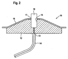
- FIG. 2 shows a contact and / or coupling device 10 for connecting the carrier 7 together with its coaxial conductor, in the region of the bottom surface 3 of the cooking device 2 of Figure 1, with a microwave generating device, not shown, by a coaxial pin 13 of a coaxial cable in an insulating material 2 14 is inserted.
- the coaxial cable 14 may be attached to the insulating material 12 via any attachment device (not shown).
- a recess 15 is provided, in the bottom region of which the tip of the coaxial pin 13 rests.
- the insulating material 12, which may be, for example, a ceramic, such as steatite or glass, is arranged in a bulge of the cooking chamber wall 16 of the bottom surface 3 of the cooking appliance shown in FIG.
- This cooking chamber wall 16 has an opening 17 which lies over the recess 15 of the insulating material 12.
- the connecting element can be a bolt 18. If the bolt 18 is inserted into the recess 15 of the insulating material 12, a contact connection between the tip of the coaxial pin 13 and the connecting element 18 of the coaxial conductor of the carrier 7 is made possible.
- the supplied via the coaxial cable 14 microwave radiation can be transmitted through the contact and / or coupling device to the connection element 18 of the coaxial conductor to be finally decoupled within the cooking chamber 1 to the extraction point 9 via antennas.
- the decoupling can take place regulated via a power control device, not shown.
- coaxial conductors may be attached to the contact and / or coupling means with respective terminal members to enable coupling via the coaxial pin 13 and coaxial cable 14 to the microwave generating means.
- the coupling interchangeable coaxial conductor (accessories) to the microwave generating device and on the other hand a flexible connection between two conductors (coaxial pin and coaxial conductor) provided in the interior of the insulating material 2.
- a coaxial conductor for transporting microwaves into a cooking space can also be integrated into a tray rack, which in turn has two carriers 7'a, 7'b running substantially vertically in the cooking space and a plurality of substantially horizontally extending insert bars 8 ', only one of which is shown. Both the carriers 7'a, 7'b and the insertion strips 8 'are formed substantially U-shaped for this purpose, accommodate in their interior round conductors 103'a, 103'b, 103'c and are grounded.
- coaxial conductors are provided by the tray rack 7'a, 7'b, 8 'together with the round conductors 103'a, 103'b, 103'c, in a particularly cost-saving and space-saving manner.
- the U-configuration of the tray rack profile also allows drainage of liquid.
- microwave energy can be fed via a microwave generating device, not shown, into a contact and / or coupling device 100 'which is arranged in the bottom of a cooking appliance (not shown) and in turn not only a feedthrough 101'. for microwave but also a T-shaped splitter 102 'to microwave energy to the round conductor 103'a, 103'b in the two carriers 7'a, 7'b of the oven rack to come, so that the tray rack to the contact and / Coupling 100 'rotatably installed in a cooking chamber.
- the feedthroughs 101 'as well as the splitter 102' must be conducted in isolation through the cooking chamber bottom, without a corresponding insulation being shown in detail in FIG.
- antennas 103'a, 103'b, 103'c antennas not shown are attachable, in particular weldable.
- the antennas can be provided either in the region of the two carriers 7'a and 7'b or the insertion strips 8 '.
Abstract
Description
Die vorliegende Erfindung betrifft ein Gargerät mit einem Garraum, einer Mikrowellenerzeugungseinrichtung und zumindest einem Koaxial- oder Streifenleiter innerhalb des Garraums, der mit der Mikrowellenerzeugungseinrichtung verbunden ist und über den von der Mikrowellenerzeugungseinrichtung erzeugte Mikrowellenstrahlung innerhalb des Garraums auskoppelbar ist.The present invention relates to a cooking appliance having a cooking chamber, a microwave generating device and at least one coaxial or strip conductor within the cooking chamber, which is connected to the microwave generating device and can be coupled out via the microwave radiation generated by the microwave generating device within the cooking chamber.
Gargeräte mit einer Mikrowellenerzeugungseinrichtung sind aus dem Stand der Technik vielfältig bekannt. So können beispielsweise Mikrowellenerzeugungseinrichtungen in einem herkömmlichen Umluftgargerät integriert sein, oder es sind Gargeräte bekannt, mit denen lediglich ein Garen auf Basis von Mikrowellenstrahlung möglich ist.Cooking appliances with a microwave generating device are widely known from the prior art. For example, microwave generating devices may be integrated in a conventional circulating air cooking appliance, or cooking appliances are known with which only cooking based on microwave radiation is possible.
Ein besonderes Problem für Mikrowellengargeräte ist der gleichmäßige Energieeintrag über mehrere Behandlungs- bzw. Einschubebenen für Gargut. Häufig ist es lediglich möglich, nur ein bis zwei Einschubebenen zur Erwärmung des Garguts unter Zuhilfenahme von Mikrowellenenergie zu nutzen, wobei in der Regel für jede nutzbare Einschubebene eine eigene Mikrowellenerzeugungseinrichtung (beispielsweise umfassend ein Magnetron) verwendet wird. Herkömmlicherweise wird die Mikrowellenstrahlung von der Mikrowellenerzeugungseinrichtung zum Garraum über Hohlleiter transportiert, die verhältnismäßig viel Bauraum benötigen. Insbesondere wenn mehrere Einschubebenen in einem Garraum eines Gargeräts mit Mikrowellenleistung beaufschlagt werden sollen, ist der erforderliche Platzbedarf für diese Hohlleiter nachteilig.A particular problem for Mikrowellengargeräte is the uniform energy input over several treatment or insertion levels for food. Often it is only possible to use only one or two insertion levels for heating the food with the aid of microwave energy, usually for each usable shelf level own microwave generating device (for example, comprising a magnetron) is used. Conventionally, the microwave radiation is transported from the microwave generating device to the cooking chamber via waveguides, which require a relatively large amount of space. In particular, when several insertion levels are to be applied in a cooking chamber of a cooking appliance with microwave power, the required space for these waveguide is disadvantageous.
Die WO 01/82653 A1 offenbart ein Mikrowellengargerät mit einer Vielzahl von Ebenen, die jeweils mit Mikrowellen bestrahlt werden können. Dabei weist das Mikrowellengargerät auf jeder Ebene einen Hohlleiter mit einer Vielzahl von Öffnungen auf, die Mikrowellenstrahlung auf in die Ebenen eingebrachtes Gargut horizontal abstrahlen. Jede Ebene weist einen separaten Mikrowellenerzeuger auf.WO 01/82653 A1 discloses a microwave cooking appliance having a plurality of levels, each of which can be irradiated with microwaves. In this case, the Mikrowellengargerät on each level on a waveguide with a plurality of openings, the microwave radiation radiate horizontally on introduced into the levels of food. Each level has a separate microwave generator.
Die US 4,329,557 beschreibt ein Mikrowellengargerät, das über mehrere Ebenen verfügen kann. Mikrowellenstrahlung tritt über eine Öffnung in einen Garraum ein, wird von einem Blech umgelenkt und kann über seitlich angeordnete Hohlleiter von einem oberen Bereich des Garraums zu einem unteren Bereich des Garraums geleitet werden. Die Hohlleiter können Schlitze aufweisen, in die ein Brett zur Aufnahme eines Garguts eingeschoben werden kann. Durch die Hohlleiter soll erreicht werden, daß auch ein in dem unteren Bereich des Mikrowellengargeräts eingebrachtes Gargut gleichmäßig erwärmt werden kann.US 4,329,557 describes a microwave cooking appliance which may have multiple levels. Microwave radiation enters via an opening in a cooking chamber, is deflected by a metal sheet and can be passed via laterally arranged waveguide from an upper portion of the cooking chamber to a lower portion of the cooking chamber. The waveguides may have slots into which a board for receiving a food can be inserted. Through the waveguide is to be achieved, that even in the lower portion of the microwave cooking appliance introduced food can be heated evenly.
Aus der WO 97/19576 A1 ist ein Mikrowellengargerät mit einem Garraum bekannt, in den über mehrere Öffnungen Mikrowellenstrahlung eingebracht werden kann. Um das Garen besser steuern zu können, können Hohlleiter von einer Mikrowellenquelle zu den Öffnungen mittels Verschlußmitteln verschlossen werden.From WO 97/19576 A1 a Mikrowellengargerät with a cooking chamber is known, in which microwave radiation can be introduced via a plurality of openings. In order to better control the cooking, waveguides can be closed by a microwave source to the openings by means of closure means.
Aus der WO 03/079729 A2 ist ein Mikrowellengargerät bekannt, bei dem ein Gargut in einem Garraum dadurch erkannt werden kann, daß über eine kleine Öffnung des Garraums reflektierte Mikrowellenstrahlung nach außen geleitet und von einem Sensor detektiert werden kann. Über die Energie der austretenden Mikrowellenstrahlung kann geschlossen werden, ob und was für ein Gargut sich im Inneren des Garraums befindet.From WO 03/079729 A2 a Mikrowellengargerät is known in which a food can be detected in a cooking chamber characterized in that over a small opening of the cooking chamber reflected microwave radiation can be directed to the outside and detected by a sensor. About the energy of the exiting microwave radiation can be concluded whether and what is a food inside the cooking chamber.
Die US 4,507,531 offenbart ein Mikrowellengargerät mit einem Garraum, bei dem eine Ausgangsleistung eines Magnetrons über einen Anodenstrom als Regelgröße geregelt wird, damit ein Garprozeß immer gleich ausführbar ist, da die Leistung des Magnetrons genau kontrolliert werden kann.US Pat. No. 4,507,531 discloses a microwave cooking appliance with a cooking chamber in which an output power of a magnetron is regulated via an anode current as a controlled variable so that a cooking process can always be carried out in the same way since the power of the magnetron can be precisely controlled.
Ein Gargerät mit einer Mikrowellenerzeugungseinrichtung ist auch aus der US 2004/0004074 A1 bekannt, wobei dieses Mikrowellengargerät eine spezielle Mikrowellenauskopplung zur Vergleichmäßigung des Energieeintrags in Gargut im Garraum nutzt. Genauer gesagt ist der Garraum dieses Gargeräts mit mehreren Ausstrahlöffnungen für Mikrowellen ausgerüstet, wobei bspw. eine erste Ausstrahlöffnung elektromagnetische Strahlung über Reflexion zu einer zweiten Ausstrahlöffnung im Garraum weiterleitet. Reflektierte elektromagnetische Strahlung kann über die zweite Ausstrahlöffnung auch zu einer dritten Ausstrahlöffnung weitergeleitet werden. Schließlich kann über die dritte Ausstrahlöffnung reflektierte elektromagnetische Strahlung zu einer Last weitergeleitet werden, deren Temperatur gemessen werden kann. Die verschiedenen Ausstrahlöffnungen des Mikrowellengargeräts stehen mit einem Streifenleiter in Wirkverbindung, der außerhalb des Garraums angeordnet ist. Die Auskopplung der Strahlung erfolgt an den Garraumwänden.A cooking appliance with a microwave generating device is also known from US 2004/0004074 A1, wherein this Mikrowellengargerät a special microwave decoupling for Homogenization of the energy input in food to be cooked in the cooking uses. More precisely, the cooking chamber of this cooking appliance is equipped with a plurality of microwave discharge openings, wherein, for example, a first discharge opening forwards electromagnetic radiation via reflection to a second discharge opening in the cooking space. Reflected electromagnetic radiation can also be forwarded via the second emission opening to a third emission opening. Finally, electromagnetic radiation reflected via the third emission opening can be forwarded to a load whose temperature can be measured. The various radiation openings of the microwave cooking appliance are in operative connection with a strip conductor which is arranged outside the cooking chamber. The decoupling of the radiation takes place at the cooking chamber walls.
In der US 5,170,142 ist ein hermetischer Anschluß eines Koaxialkabelpins an einen inneren Stromkreis in einer Radiofrequenzvorrichtung offenbart, wobei der Koaxialkabelpin von einem Glasmaterial und einem dielektrischen Material umgeben ist. Das Glasmaterial wird auf seine Schmelztemperatur erwärmt und anschließend in ein Gehäuse eingeführt, um nach Abkühlung durch eine dichte Verbindung mit dem Gehäuse eine hermetische Abdichtung zu bilden. Der Koaxialkabelpin wird somit fest über das Glasmaterial mit dem Gehäuse verbunden.In US 5,170,142 a hermetic connection of a coaxial cable pin to an internal circuit in a radio frequency device is disclosed wherein the coaxial cable pin is surrounded by a glass material and a dielectric material. The glass material is heated to its melting temperature and then introduced into a housing to form a hermetic seal upon cooling by a sealed connection with the housing. The Koaxialkabelpin is thus firmly connected via the glass material to the housing.
Ein gattungsgemäßes Gargerät ist beispielsweise aus der US 4,600,822 bekannt, die zwar eine Mikrostreifenleitung zur Mikrowellenheizung betrifft, ohne daß jedoch Details der Anordnung derselben in dem Gargerät offenbart sind.A generic cooking appliance is known for example from US 4,600,822, although a microstrip line for microwave heating, but without details of the arrangement thereof are disclosed in the cooking appliance.
Auch aus der US 2004/0188429 A1 ist ein gattungsgemäßes Gargerät bekannt, wobei jedoch lediglich der Transport von Mikrowellen zum Garraum über ein Koaxialkabel offenbart ist.A generic cooking appliance is also known from US 2004/0188429 A1, but only the transport of microwaves to the cooking space via a coaxial cable is disclosed.
Die US 5,334,403 betrifft eine Vorrichtung zum Auftauen, Wiederaufwärmen und Trocknen von Produkten in einem abgeschlossenen Behandlungsraum durch Bewegen einer Mikrowellenquelle oberhalb einer Produktlage.US 5,334,403 relates to an apparatus for thawing, reheating and drying products in a sealed treatment room by moving a microwave source above a product layer.
Die US 6,323,471 B1 betrifft unter anderem eine Mikrowellenaufheizung unter reduziertem Druck eines zu trocknenden, zu konzentrierenden, zu entfrostenden, zu röstenden oder zu sterilisierenden Objekts unter Einsatz von Reflektorplatten zur uniformen Aufheizung.No. 6,323,471 B1 relates inter alia to microwave heating under reduced pressure of an object to be dried, to be concentrated, to be defrosted, to be roasted or sterilized using reflector plates for uniform heating.
Die DE 1 937 470 U1 betrifft einen Mikrowellenherd mit einem mehrstöckigen und drehbar ausgebildeten Hordengestell zur Aufnahme von mit den Mikrowellen zu behandelnden Gargut.DE 1 937 470 U1 relates to a microwave oven with a multi-storey and rotatably designed tray rack for receiving food to be treated with the microwaves.
Der vorliegenden Erfindung liegt die Aufgabe zugrunde, das gattungsgemäße Gargerät derart weiterzuentwickeln, daß Mikrowellenstrahlen auf platzsparende Weise von der Mikrowellenerzeugungseinrichtung zum zu bestrahlenden Gargut geleitet werden können. Auch soll die Positionierung der Mikrowellenerzeugungseinrichtung möglichst flexibel sein, ohne Dichtigkeits- oder Stabilitätsprobleme hervorzurufen. Ferner soll die Auskopplung der Mikrowellenstrahlung in den Garraum möglichst nahe am Gargut erfolgt.The present invention has for its object to further develop the generic cooking appliance such that microwave radiation can be passed in a space-saving manner from the microwave generating device to be irradiated food. Also, the positioning of the microwave generating device should be as flexible as possible without causing leaks or stability problems. Furthermore, the decoupling of the microwave radiation in the oven should be as close as possible to the food.
Diese Aufgabe wird erfindungsgemäß dadurch gelöst, daß der zumindest eine Koaxial- oder Streifenleiter in mindestens einem Glied des Gargeräts in Form einer Stütze oder eines festen Trägers innerhalb des Garraums oder in zumindest einem in den Garraum einbringbaren Zubehörteil integriert ist, wobei der Träger zum Tragen einschiebbarer Garbehälter, Platten, Bleche und/oder Wannen dient und/oder das Zubehörteil ein Einhängegestell, einen Hordengestellwagen oder ein Tellerregeneriergestell umfaßt.This object is achieved in that the at least one coaxial or strip conductor is integrated in at least one member of the cooking appliance in the form of a support or a solid support within the cooking chamber or in at least one insertable into the cooking accessory, the carrier for carrying retractable Garbehälter, plates, sheets and / or trays is used and / or the accessory includes a Einhängegestell, a cellar trolley or a Tellerregeneriergestell.
Dabei kann vorgesehen sein, daß zumindest eine Kontakt- und/oder Kopplungseinrichtung zum Verbinden des Koaxial- oder Streifenleiters, direkt oder indirekt, mit der Mikrowellenerzeugungseinrichtung im Bereich einer Garraumwand.It can be provided that at least one contact and / or coupling device for connecting the coaxial or strip conductor, directly or indirectly, with the microwave generating device in the region of a cooking chamber wall.
Ferner wird mit der Erfindung vorgeschlagen, daß eine Verbindung zwischen der Kontakt- und/oder Kopplungseinrichtung und dem Koaxial- oder Streifenleiter, insbesondere automatisch, durch Einbringen des Zuberhörteils in den Garraum herstellbar ist.It is also proposed with the invention that a connection between the contact and / or coupling device and the coaxial or strip conductor, in particular automatically, can be produced by introducing the Zuberhörteils in the oven.
Bevorzugt kann vorgesehen sein, daß die Kontakt- und/oder Kopplungseinrichtung eine Durchführung durch die Garraumwand, vorzugsweise im Bereich der Bodenfläche des Gargeräts, und/oder einen Splitter umfaßt.Preferably, it can be provided that the contact and / or coupling device comprises a passage through the cooking chamber wall, preferably in the region of the bottom surface of the cooking appliance, and / or a splitter.
Mit der Erfindung wird auch vorgeschlagen, daß die Kontakt- und/oder Kopplungseinrichtung zum Koppeln zumindest eines Koaxialleiters, insbesondere eines ersten Koaxialkabels, im Garraum mit einem Koaxialleiter eines zweiten Koaxialkabels außerhalb des Garraums über eine Steckverbindung ausgeführt ist.The invention also proposes that the contact and / or coupling device for coupling at least one coaxial conductor, in particular a first coaxial cable, in the cooking chamber with a coaxial conductor of a second coaxial cable outside the cooking chamber is designed via a plug connection.
Dabei kann vorgesehen sein, daß ein Anschlußelement, vorzugsweise in Verbindung mit dem Koaxialleiter des ersten Koaxialkabels, und ein Koaxialpin, vorzugsweise in Verbindung mit dem Koaxialleiter des zweiten Koaxialkabels, zumindest bereichsweise durch ein Isolationsmaterial und eine Garraumwand geführt sind.It can be provided that a connecting element, preferably in conjunction with the coaxial conductor of the first coaxial cable, and a Koaxialpin, preferably in conjunction with the coaxial conductor of the second coaxial cable, at least partially guided by an insulating material and a cooking chamber wall.
Gemäß der Erfindung kann dabei wiederum vorgesehen sein, daß das Anschlußelement mit dem Zubehörteil verbindbar oder verbunden ist.According to the invention it can be provided in turn that the connection element can be connected or connected to the accessory.
Mit der Erfindung wird auch vorgeschlagen, daß der Koaxialpin zumindest teilweise in dem Anschlußelement, das vorzugsweise die Form eines Bolzens aufweist, verläuft.The invention also proposes that the coaxial pin runs at least partially in the connecting element, which preferably has the shape of a bolt.
Auch kann vorgesehen sein, daß das Isolationsmaterial eine Ausnehmung aufweist, in die das Anschlußelement einsteckbar ist.It can also be provided that the insulating material has a recess into which the connecting element can be inserted.
Ferner wird erfindungsgemäß vorgeschlagen, daß in dem Bodenbereich des Isolationsmaterials der Koaxialpin angeordnet ist.Further, the invention proposes that in the bottom region of the insulating material of Koaxialpin is arranged.
Weiterhin kann vorgesehen sein, daß das Isolationsmaterial eine Keramik, wie Steatith oder Glas, umfaßt.Furthermore, it can be provided that the insulation material comprises a ceramic, such as steatite or glass.
Bevorzugte erfindungsgemäße Gargeräte sind dadurch gekennzeichnet, daß der Koaxialleiter im Garraum zumindest teilweise durch einen Leiter, vorzugsweise in Form eines Rundleiters, in einem eine Masse darstellenden Teil des Glieds, vorzugsweise in Form eines U-förmigen Profils, bereitgestellt ist.Preferred cooking devices according to the invention are characterized in that the coaxial conductor in the cooking chamber is at least partially provided by a conductor, preferably in the form of a circular conductor, in a part of the member representing a mass, preferably in the form of a U-shaped profile.
Ferner kann vorgesehen sein, daß die Mikrowellenerzeugungseinrichtung, umfassend zumindest ein Magnetron, zumindest einen Hochspannungstrafo, zumindest einen Heizungstrafo, zumindest einen Kondensator, zumindest eine Diode, zumindest ein Schaltnetzteil und/oder eine Kühleinrichtung, außerhalb des Garraums, insbesondere außerhalb des Gerätekörpers des Gargeräts, vorzugsweise in einem Unterschrank, zumindest teilweise angeordnet ist.Furthermore, it can be provided that the microwave generating device, comprising at least one magnetron, at least one high-voltage transformer, at least one heating transformer, at least one capacitor, at least one diode, at least one switched-mode power supply and / or a cooling device outside the cooking chamber, in particular outside the appliance body of the cooking appliance, preferably in a lower cabinet, at least partially arranged.
Mit der Erfindung werden auch Ausführungsformen vorgeschlagen, die gekennzeichnet sind durch zumindest eine Antenne in Wirkverbindung mit dem Koaxial- oder Streifenleiter, insbesondere angeschweißt an den Rundleiter, zur Abstrahlung von Mikrowellen in den Garraum.With the invention, embodiments are also proposed, which are characterized by at least one antenna in operative connection with the coaxial or strip conductor, in particular welded to the circular conductor, for the radiation of microwaves in the cooking chamber.
Weiterhin kann vorgesehen sein, daß das Glied, insbesondere das Zubehörteil, mit mindestens einer Einschubleiste für zumindest einen Gargutträger und zumindest einer Auskopplungsstelle, an der Mikrowellenstrahlung vom Koaxial- oder Streifenleiter in den Garraum, insbesondere über eine Antenne, auskoppelbar ist, in Wirkverbindung steht, wobei bevorzugt mehrere Auskopplungsstellen und mehrere Einschubleisten innerhalb des Garraums angeordnet sind, und zwar zueinander ausgerichtet.Furthermore, it can be provided that the member, in particular the accessory, with at least one insertion strip for at least one food support and at least one decoupling point on the microwave radiation from the coaxial or strip conductor in the cooking chamber, in particular via an antenna, is decoupled, is in operative connection, wherein preferably a plurality of coupling-out points and a plurality of insertion strips are arranged within the cooking chamber, and aligned with each other.
Dabei kann vorgesehen sein, die Auskopplungsstellen zum Auskoppeln von Mikrowellenstrahlung im wesentlichen parallel zu Behandlungsebenen für Gargut und/oder Gargutträgern ausgerichtet sind.It can be provided that the extraction points are aligned for coupling out of microwave radiation substantially parallel to treatment levels for food and / or food supports.
Mit der Erfindung wird auch vorgeschlagen, daß sich in einer Behandlungsebene, die durch zwei nahe an sich gegenüberliegenden Garraumwänden angeordneten Einschubleisten bestimmt ist, Auskopplungsstellen, diametral oder direkt, gegenüberstehen.With the invention it is also proposed that in a treatment level, which is determined by two arranged close to opposite Garraumwänden Einschubleisten, coupling points, diametrically or directly opposed.
Erfindungsgemäß kann weiterhin vorgesehen sein, daß jede Einschubleiste zwischen zwei Trägern, insbesondere in Form von Hordengestellsäulen, verläuft, die mit zumindest einer Kontakt- und/oder Kopplungseinrichtung, vorzugsweise unter Zwischenschaltung eines Splitters, verbindbar sind.According to the invention may further be provided that each insertion strip between two carriers, in particular in the form of Horwerkgestellsäulen runs, which are connectable to at least one contact and / or coupling device, preferably with the interposition of a splitter.
Gemäß der Erfindung kann ferner vorgesehen sein, daß das Glied, insbesondere das Zubehörteil, benachbart zu einem innerhalb des Gargeräts vorgesehenen Lüfterrad angeordnet ist, lösbar und/oder bewegbar ist.According to the invention can also be provided that the member, in particular the accessory, is disposed adjacent to a provided inside the cooking fan impeller, is detachable and / or movable.
Schließlich wird mit der Erfindung vorgeschlagen, daß dasselbe mit Heißluft und/oder Dampf betreibbar ist.Finally, it is proposed with the invention that the same with hot air and / or steam is operable.
Der Erfindung liegt somit die überraschende Erkenntnis zugrunde, daß es mit dem erfindungsgemäßen Gargerät möglich ist, die Raumerfordernisse zur Leitung von Mikrowellenstrahlung in einen Garraum dadurch zu verringern, daß Koaxial- oder Streifenleiter innerhalb des Garraums eingesetzt werden, die zur Auskopplung von Mikrowellenstrahlung in den Garraum in einem festen Träger innerhalb des Garraums oder in einem in einen Garraum einbringbaren Zubehörteil integriert sind. Besonders vorteilhaft ist es dabei, wenn die Koaxialleiter gebildet werden durch Rundleiter, die in geerdeten U-förmigen Profilen des Trägers oder Zubehörteils, insbesondere in Form eines Hordengestells, verlaufen. Der Einsatz solcher Koaxial- oder Streifenleiter innerhalb des Garraums ermöglicht eine flexible Anpassung an das in den Garraum eingebrachte Gargut, insbesondere dessen Plazierung, damit die Auskopplung der Mikrowellenstrahlung möglichst nahe am Gargut erfolgen kann. Zu diesem Zwecke können der Träger oder das Zubehörteil bevorzugt eine oder mehrere Auskopplungsstelle(n) aufweisen, die in unterschiedlichen Höhen innerhalb des Garraums angeordnet werden können, um die Auskopplung von Mikrowellenstrahlen in Bezug auf Behandlungsebenen für Gargut zu optimieren. Beispielsweise kann an einen Rundleiter eine Antenne direkt angeschweißt sein, die durch eine Öffnung in einem Profil des Hordengestells hindurchtreten kann. Sind in mehreren Trägern oder Zubehörteilen Koaxial- oder Streifenleiter integriert, können die einzelnen Auskopplungsstellen so eingestellt werden, daß sie sich, beispielsweise diagonal, gegenüberliegen. Ebenfalls können Koaxial- oder Streifenleiter in sämtlichen Trägern oder Stützen von Zubehörteilen integriert sein. Wird die Strahlrichtung der Mikrowellenstrahlen aus der Auskopplungsstelle parallel zu den Behandlungsebenen geführt, kann ein besonders guter Energieeintrag in das zu erwärmende Gargut erzielt werden.The invention is therefore based on the surprising finding that it is possible with the cooking appliance according to the invention to reduce the space requirements for directing microwave radiation into a cooking space in that coaxial or strip conductors are used within the cooking chamber, which is used to decouple microwave radiation in the oven are integrated in a solid support within the cooking chamber or in an insertable into a cooking accessory. It is particularly advantageous if the coaxial conductors are formed by round conductors which run in grounded U-shaped profiles of the carrier or accessory, in particular in the form of a tray rack. The use of such coaxial or strip conductors within the cooking chamber allows flexible adaptation to the cooking product introduced into the cooking chamber, in particular its placement, so that the coupling of the microwave radiation can be as close as possible to the food. For this purpose, the carrier or the accessory may preferably have one or more extraction points which can be arranged at different heights within the cooking chamber in order to optimize the extraction of microwave radiation with respect to treatment levels for food to be cooked. For example, an antenna can be directly welded to a round conductor, which antenna can pass through an opening in a profile of the oven rack. If coaxial or strip conductors are integrated in several carriers or accessories, the individual outcoupling points can be adjusted so that they face each other, for example diagonally. Coaxial or strip conductors may also be integrated in all carriers or supports of accessories. Will the beam direction of the microwave rays turn off led out of the extraction point parallel to the treatment levels, a particularly good energy input can be achieved in the food to be heated.
Ist ein Koaxial- oder Streifenleiter in einem Zubehörteil integriert, so ist es vorteilhaft, wenn eine Kontakt- und/oder Kopplungseinrichtung vorgesehen ist, über die das Zubehörteil mit einer außerhalb des Garraums angeordneten Mikrowellenerzeugungseinrichtung verbunden ist. Eine solche Kontakt- und/oder Kopplungseinrichtung ist bevorzugt im Bereich einer Gehäusewand des Garraums angeordnet, an welche sich innerhalb des Garraums der Koaxial- oder Streifenleiter anschließt. Außerhalb des Garraums kann als Verbindungsleitung zwischen der Mikrowellenerzeugungseinrichtung und der Kontakt- und/oder Kopplungseinrichtung ein Koaxialkabel verwendet werden. Die Kontakt- und/oder Kopplungseinrichtung kann dabei vorteilhafterweise elektrisch und/oder magnetisch abgeschirmt, dampfdicht und/oder bis zu einer Temperatur von zumindest 250°C, vorzugsweise 300°C, temperaturstabil. Ebenfalls bevorzugt ist, daß der Koaxial- oder Streifenleiter bis zu einer Temperatur von zumindest 250°C, bevorzugt 300°C, temperaturbeständig ist und/oder eine Leistung von etwa 1KW transportiert.If a coaxial or strip conductor is integrated in an accessory, then it is advantageous if a contact and / or coupling device is provided, via which the accessory is connected to a microwave generating device arranged outside the cooking chamber. Such a contact and / or coupling device is preferably arranged in the region of a housing wall of the cooking chamber, which is followed by the coaxial or strip conductor within the cooking chamber. Outside the cooking chamber can be used as a connecting line between the microwave generating device and the contact and / or coupling a coaxial cable. The contact and / or coupling device can advantageously electrically and / or magnetically shielded, vapor-tight and / or up to a temperature of at least 250 ° C, preferably 300 ° C, temperature stable. It is also preferred that the coaxial or strip conductor is temperature-resistant up to a temperature of at least 250 ° C., preferably 300 ° C., and / or transports a power of about 1KW.
Vorteilhaft für die Erfindung ist daher, daß Mikrowellenenergie von einer Mikrowellenerzeugungseinrichtung zu einer Gehäusewand eines Garraums beispielsweise über Koaxialkabel, geleitet werden kann, die bislang in Gargeräten und bei Leistungen von etwa 1 kW nicht eingesetzt wurden. Die Leitung über Koaxialkabel ermöglicht eine flexible Gestaltung und Positionierung der mikrowellenerzeugenden Komponenten, die neben einem Magnetron auch ein Hochspannungstrafo, ein Heizungstrafo, Kondensatoren, Dioden und ein Schaltnetzteil umfassen können. Ebenfalls ermöglicht der Einsatz von Koaxialkabeln eine flexible Kühlung dieser Komponenten, z.B. auch außerhalb des eigentlichen Gargerätekorpus in einem dafür ausgestatteten Unterschrank oder ähnlichem.Advantageous for the invention is therefore that microwave energy from a microwave generating device to a housing wall of a cooking chamber, for example via coaxial cable, can be passed, which have not been used in cooking appliances and at powers of about 1 kW. Coaxial cable routing allows for flexible design and positioning of the microwave generating components which, in addition to a magnetron, may also include a high voltage transformer, a heating transformer, capacitors, diodes, and a switched mode power supply. Also, the use of coaxial cables allows flexible cooling of these components, e.g. also outside of the actual Gargerätekorpus in a dedicated cabinet or the like.
Durch die Kontakt- und/oder Kopplungseinrichtung kann zudem eine Kopplung eines Koaxialpins eines Koaxialkabels mit einem, beispielsweise auch austauschbaren, im Garraum angeordneten Koaxialleiter durch eine Gehäusewand erfolgen. Der Koaxialleiter innerhalb des Garraums wird zu diesem Zweck über ein Anschlußelement in Isolationsmaterial eingesetzt und kann jederzeit durch beliebige andere Koaxialleiter mit entsprechenden Anschlußelementen ausgetauscht werden. Durch diese Austauschbarkeit kann das Gargerät flexibler genutzt werden.In addition, the coupling and / or coupling device can be used to couple a coaxial pin of a coaxial cable with a coaxial conductor, for example, also interchangeable, arranged in the cooking chamber through a housing wall. The coaxial conductor within the cooking chamber is used for this purpose via a connecting element in insulating material and can at any time by any other coaxial conductor with corresponding connection elements be replaced. Due to this interchangeability, the cooking appliance can be used more flexibly.
Die erfindungsgemäße Kontakt- und/oder Kopplungseinrichtung ermöglicht ferner die Überprüfung der Mikrowellenkompatibilität bspw. eines Zubehörteils des Gargeräts. Ist ein in die Ausnehmung des Isolationsmaterials eingestecktes Anschlußelement des Zubehörteils nicht mikrowellenkompatibel, kann über eine Steuer- oder Regeleinrichtung, die mit einer Überprüfungsvorrichtung in Wirkverbindung steht, die Mikrowellenerzeugungseinrichtung ausgeschaltet werden. Dadurch kann eine Beschädigung des Gargeräts und der Zubehörteile verhindert werden. Mit anderen Worten ist das erfindungsgemäße Gargerät auch gefahrlos mit Standardzubehör betreibbar, also ohne Einkopplung von Mikrowellen.The contact and / or coupling device according to the invention also makes it possible to check the microwave compatibility of, for example, an accessory of the cooking appliance. Is a plugged into the recess of the insulating material connecting element of the accessory is not microwave compatible, can be switched off via a control or regulating device, which is in operative connection with a verification device, the microwave generating device. This can prevent damage to the cooking appliance and accessories. In other words, the cooking appliance according to the invention is also safe to operate with standard accessories, ie without coupling of microwaves.
Die Anzahl an Trägern oder Zubehörteilen, in denen Koaxial- oder Streifenleiter integriert sind, kann je nach Gargerätgröße bzw. Größe von Einschubbehälter, in denen Gargut erwärmt werden soll, eingestellt werden.The number of carriers or accessories in which coaxial or strip conductors are integrated can be adjusted depending on the size of the cooking appliance or the size of drawer containers in which food is to be heated.
Desweiteren kann ein erfindungsgemäßes Gargerät mit einer Lasterkennungseinrichtung vorgesehen sein, wobei über die Lasterkennungseinrichtung vorzugsweise eine Auswertung absorbierter und/oder reflektierter Mikrowellenstrahlung, eine Anodenstrommessung an der Mikrowellenerzeugungseinrichtung oder eine Messung einer elektromagnetischen Störung, insbesondere unter Ausnutzung der Bluetooth-Technologie, durchführbar ist. Mit dieser Lasterkennung der absorbierten oder reflektierten Mikrowellenstrahlung kann eine intelligente Steuerung der benötigten Mikrowellenleistung bezogen auf unterschiedliche Behandlungsebenen oder gar Gargutbehälter ermöglicht werden. Somit kann die Zeitdauer, die Intensität und der Ort der Mikrowellenleistung durch Art und Umfang der Beschickung des Gargeräts über entsprechende Garprogramme gesteuert werden. Bevorzugt erfolgt die Lasterkennung automatisch.Furthermore, a cooking appliance according to the invention can be provided with a load recognition device, wherein the load recognition device can preferably carry out an evaluation of absorbed and / or reflected microwave radiation, an anode current measurement at the microwave generation device or a measurement of an electromagnetic interference, in particular using the Bluetooth technology. With this load detection of the absorbed or reflected microwave radiation, an intelligent control of the required microwave power based on different treatment levels or even food containers can be made possible. Thus, the duration, the intensity and the location of the microwave power can be controlled by the type and extent of the feed of the cooking appliance via appropriate cooking programs. Preferably, the load detection is done automatically.
Über eine Leistungsregelungseinrichtung können die verschiedenen Bereiche des Garraums, bspw. die unterschiedlichen Behandlungsebenen für Gargut, separat geregelt werden. Die Leistungsregelungseinrichtung zum insbesondere individuellen Regeln der Leistung von Mikrowellenstrahlung an jeder Auskopplungsstelle derselben im Garraum erhöht die Garpräzision. Dabei kann die Leistungsregelungseinrichtung zumindest ein Verschlußmittel für die Auskopplungsstellen zum teilweisen oder vollständigen Verschließen derselben umfassen.About a power control device, the different areas of the cooking chamber, eg. The different treatment levels for food to be controlled separately. The power control device for particularly individual regulation of the power of microwave radiation at each output point thereof in the cooking chamber increases the cooking precision. In this case, the power control device may comprise at least one closure means for the extraction points for partially or completely closing the same.
Der Koaxial- oder Streifenleiter kann selbst platzsparend, ähnlich einem bzw. um ein Gaswärmetauscher, an einem Lüfterrad angeordnet werden.The coaxial or strip conductor can even be arranged in a space-saving manner, similar to or around a gas heat exchanger, on a fan wheel.
Weiterhin kann eine Steuer- oder Regeleinrichtung in Wirkverbindung mit der Mikrowellenerzeugungseinrichtung, der Lasterkennungseinrichtung, der Kontakt- und/oder Kopplungseinrichtung, der Überprüfungseinrichtung, der Leistungsregelungseinrichtung, mindestens einer Auskopplungsstelle, mindestens einem Verschlußmittel und/oder mindestens einem Sensor, vorzugsweise zum Bestimmen der Temperatur innerhalb des Garraums, bei einem erfindungsgemäßen Gargerät vorgesehen sein.Furthermore, a control or regulating device in operative connection with the microwave generating device, the load detection device, the contact and / or coupling device, the checking device, the power control device, at least one extraction point, at least one closure means and / or at least one sensor, preferably for determining the temperature within the cooking chamber, be provided at a cooking appliance according to the invention.
Weitere Merkmale und Vorteile der Erfindung ergeben sich beispielhaft aus der nachfolgenden detaillierten Beschreibung zweier bevorzugter Ausführungsformen der Erfindung anhand einer schematischen Zeichnung. Dabei zeigt
Figur 1- eine perspektivische Ansicht eines erfindungsgemäßen Gargeräts;
- Figur 2
- einen Querschnitt durch eine Kontakt- und/oder Kopplungseinrichtung in dem
Gargerät von Figur 1; und Figur 3- eine perspektivische Teilansicht eines Hordengestells eines weiteren erfindungsgemäßen Gargeräts.
- FIG. 1
- a perspective view of a cooking appliance according to the invention;
- FIG. 2
- a cross-section through a contact and / or coupling device in the cooking appliance of Figure 1; and
- FIG. 3
- a partial perspective view of a tray rack of another cooking appliance according to the invention.
Die Figur 1 zeigt einen Garraum 1 eines erfindungsgemäßen Gargeräts 2, der von einer Bodenfläche 3, Seitenwänden 4 und einer Abdeckung 5 umgrenzt wird, wobei eine Öffnung 6 definiert wird, die beispielsweise durch eine nicht gezeigte Gargerätetür verschlossen werden kann. Innerhalb des Garraums 1 sind vier Träger 7 angeordnet, von denen in Figur 1 drei erkannt werden können. An den Trägern 7 sind Einschubleisten 8 angeordnet, in die beispielsweise Bleche zum Abstützen von Garbehältern (nicht gezeigt) oder dergleichen eingeschoben und somit im Garraum plaziert werden können. Zumindest ein Träger 7 ist mit einem Koaxialleiter ausgeführt, d.h. in dem Träger 7 ist ein Koaxialleiter integriert. Der als Koaxialleiter ausgeführte Träger 7 weist mehrere Auskopplungsstellen 9 auf, die in Antennen übergehen, über die Mikrowellenstrahlung vom Koaxialleiter in den Garraum 1 abgegeben werden kann. Wie aus Figur 1 erkannt werden kann, korrespondiert die Anordnung jeder Auskopplungsstelle 9 bzw. Antenne mit einer Einschubleiste 8, so daß für jeden auf einer Einschubleiste 8 eingeschobenen Garbehälter zumindest eine Auskopplungsstelle 9 entlang des Trägers 7 vorliegt.1 shows a
Figur 2 zeigt eine Kontakt- und/oder Kopplungseinrichtung 10 zur Verbindung des Trägers 7 samt seinem Koaxialleiter, und zwar im Bereich der Bodenfläche 3 des Gargeräts 2 von Figur 1, mit einer nicht gezeigten Mikrowellenerzeugungseinrichtung, indem in einem Isolationsmaterial 2 ein Koaxialpin 13 eines Koaxialkabels 14 eingesteckt ist. Das Koaxialkabel 14 kann über eine beliebige Befestigungsvorrichtung (nicht gezeigt) an dem Isolationsmaterial 12 befestigt sein. In dem Isolationsmaterial 12 ist eine Ausnehmung 15 vorgesehen, in deren Bodenbereich die Spitze des Koaxialpins 13 anliegt. Das Isolationsmaterial 12, das beispielsweise eine Keramik, wie Steatith oder Glas, sein kann, ist in einer Ausbauchung der Garraumwand 16 der Bodenfläche 3 des in Figur 1 gezeigten Gargeräts angeordnet. Diese Garraumwand 16 weist eine Öffnung 17 auf, die über der Ausnehmung 15 des Isolationsmaterials 12 liegt. Durch die Öffnung 17 und in die Ausnehmung 15 ist ein Anschlußelement des Koaxialleiters des Trägers 7 des in Figur 1 gezeigten Gargeräts 2 einsetzbar. Das Anschlußelement kann dabei ein Bolzen 18 sein. Ist der Bolzen 18 in die Ausnehmung 15 des Isolationsmaterials 12 eingesetzt, so wird eine Kontaktverbindung zwischen der Spitze des Koaxialpins 13 und dem Anschlußelement 18 des Koaxialleiters des Trägers 7 ermöglicht. Somit kann die über das Koaxialkabel 14 gelieferte Mikrowellenstrahlung durch die Kontakt- und/oder Kopplungseinrichtung an das Anschlußelement 18 des Koaxialleiters übermittelt werden, um schließlich innerhalb des Garraums 1 an den Auskopplungsstelle 9 über Antennen ausgekoppelt zu werden. Die Auskopplung kann über eine nicht gezeigte Leistungsreglungseinrichtung geregelt stattfinden.2 shows a contact and / or
Wie ohne weiteres ersichtlich ist, können die unterschiedlichsten Koaxialleiter mit entsprechenden Anschlußelementen an die Kontakt- und/oder Kopplungseinrichtung angefügt werden, um eine Kopplung über den Koaxialpin 13 und das Koaxialkabel 14 an die Mikrowellenerzeugungseinrichtung zu ermöglichen. Erfindungsgemäß wird somit zum einen die Ankopplung austauschbarer Koaxialleiter (Zubehörteile) an die Mikrowellenerzeugungseinrichtung ermöglicht und zum anderen eine flexible Verbindung zwischen zwei Leitern (Koaxialpin und Koaxialleiter) im Inneren des Isolationsmaterials 2 bereitgestellt.As will be readily apparent, a variety of coaxial conductors may be attached to the contact and / or coupling means with respective terminal members to enable coupling via the
Wie aus Figur 3 ersichtlich, kann auch erfindungsgemäß ein Koaxialleiter zum Transport von Mikrowellen in einen Garraum in ein Hordengestell integriert sein, das seinerseits zwei im wesentlichen vertikal im Garraum verlaufende Träger 7'a, 7'b und eine Vielzahl dazwischen im wesentlichen horizontal verlaufender Einschubleisten 8', von denen nur eine dargestellt ist, aufweist. Sowohl die Träger 7'a, 7'b als auch die Einschubleisten 8' sind zu diesem Zwecke im wesentlichen U-förmig ausgebildet, beherbergen in ihrem Inneren Rundleiter 103'a, 103'b, 103'c und liegen auf Masse. Somit werden durch das Hordengestell 7'a, 7'b, 8' samt der Rundleiter 103'a, 103'b, 103'c Koaxialleiter bereitgestellt, und zwar auf besonders kosten- und platzsparende Weise. Die U-Konfiguration des Hordengestellprofils ermöglicht zudem einen Abfluß von Flüssigkeit.As can be seen from FIG. 3, according to the invention, a coaxial conductor for transporting microwaves into a cooking space can also be integrated into a tray rack, which in turn has two carriers 7'a, 7'b running substantially vertically in the cooking space and a plurality of substantially horizontally extending insert bars 8 ', only one of which is shown. Both the carriers 7'a, 7'b and the insertion strips 8 'are formed substantially U-shaped for this purpose, accommodate in their interior round conductors 103'a, 103'b, 103'c and are grounded. Thus, coaxial conductors are provided by the tray rack 7'a, 7'b, 8 'together with the round conductors 103'a, 103'b, 103'c, in a particularly cost-saving and space-saving manner. The U-configuration of the tray rack profile also allows drainage of liquid.
Besonders vorteilhaft ist bei der Ausführungsform gemäß Figur 3 auch, daß Mikrowellenenergie über eine nicht gezeigte Mikrowellenerzeugungseinrichtung in eine Kontakt- und/oder Kopplungseinrichtung 100' eingespeist werden kann, die in dem Boden eines nicht gezeigten Gargeräts angeordnet ist und ihrerseits nicht nur eine Durchführung 101' für Mikrowellen sondern auch einen T-förmigen Splitter 102' aufweist, um Mikrowellenenergie den Rundleiter 103'a, 103'b in den beiden Trägern 7'a, 7'b des Hordengestells zuführen zu kommen, so daß das Hordengestell um die Kontakt- und/oder Kopplungseinrichtung 100' drehbeweglich in einem Garraum installierbar ist. Selbstverständlich müssen die Durchführen 101' sowie der Splitter 102' isoliert durch den Garraumboden geführt werden, ohne daß eine entsprechende Isolation im Detail in Figur 3 dargestellt ist.It is also particularly advantageous in the embodiment according to FIG. 3 that microwave energy can be fed via a microwave generating device, not shown, into a contact and / or coupling device 100 'which is arranged in the bottom of a cooking appliance (not shown) and in turn not only a
An die Rundleiter 103'a, 103'b, 103'c sind nicht gezeigte Antennen anbringbar, insbesondere anschweißbar. Die Antennen können dabei entweder im Bereich der beiden Trägern 7'a und 7'b oder der Einschubleisten 8' bereitgestellt werden.To the round conductors 103'a, 103'b, 103'c antennas not shown are attachable, in particular weldable. The antennas can be provided either in the region of the two carriers 7'a and 7'b or the insertion strips 8 '.
In der Einbausituation sind zwei Hordengestelle gemäß Figur 3 an zwei sich gegenüberliegenden Seiten in einem Garraum eines Gargerätes angeordnet, so daß durch zwei sich auf einer Höhe befindende Einschubleisten 8' eine Behandlungsebene für Gargut definiert wird, das über die Antennen gezielt mit Mikrowellen zu beaufschlagen ist.In the installation situation two rack racks are arranged according to Figure 3 on two opposite sides in a cooking chamber of a cooking appliance, so that by two on a height level Einschubleisten 8 'is defined a treatment level for food to be acted upon by the antennas targeted with microwaves.
Die in der vorstehenden Beschreibung, in der Zeichnung sowie in den Ansprüchen offenbarten Merkmale der Erfindung können sowohl einzeln als auch in jeder beliebigen Kombination für die Verwirklichung der Erfindung in ihren verschiedenen Ausführungsformen wesentlich sein.The features of the invention disclosed in the foregoing description, in the drawing and in the claims may be essential both individually and in any combination for the realization of the invention in its various embodiments.
- 11
- Garraumoven
- 22
- GargerätCooking appliance
- 33
- Bodenflächefloor area
- 44
- SeitenwandSide wall
- 55
- Abdeckungcover
- 66
- Öffnungopening
- 7, 7'a, 7'b7, 7'a, 7'b
- Trägercarrier
- 8, 8'8, 8 '
- Einschubleisteinsertion strip
- 99
- Auskopplungsstelledecoupling point
- 1010
- Kopplungseinrichtungcoupling device
- 1212
- Isolationsmaterialinsulation material
- 1313
- Koaxialpincoaxial pin
- 1414
- Koaxialkabelcoaxial
- 1515
- Ausnehmungrecess
- 1616
- Garraumwandcooking chamber
- 1717
- Öffnungopening
- 1818
- Bolzenbolt
- 100'100 '
- Kontakt- und/oder KopplungseinrichtungContact and / or coupling device
- 101'101 '
- Durchführungexecution
- 102'102 '
- Splittersplinter
- 103'a, 103'b, 103'c103'a, 103'b, 103'c
- Rundleiterround conductor
Claims (20)
der zumindest eine Koaxial- oder Streifenleiter (7'a, 103'a; 7'b, 103'b; 8', 103'c) in mindestens einem Glied des Gargeräts (2) in Form einer Stütze oder eines festen Trägers (7, 7'a, 7'b) innerhalb des Garraums (1) oder in zumindest einem in den Garraum einbringbaren Zubehörteil (7, 7'a, 7'b, 8') integriert ist, wobei der Träger (7, 7'a, 7'b) zum Tragen einschiebbarer Garbehälter, Platten, Bleche und/oder Wannen dient und/oder das Zubehörteil (7, 7'a, 7'b, 8, 8') ein Einhängegestell, einen Hordengestellwagen oder ein Tellerregeneriergestell umfaßt.Cooking appliance (2) with a cooking chamber (1), a microwave generating device and at least one coaxial or strip conductor (7'a, 103'a;7'b,103'b; 8 ', 103'c) within the cooking chamber (1) , which is connected to the microwave generating device and can be coupled out via the microwave radiation generated by the microwave generating means within the cooking chamber (1), characterized in that
the at least one coaxial or strip conductor (7'a, 103'a, 7'b, 103'b, 8', 103'c) in at least one member of the cooking appliance (2) in the form of a support or a solid support (7 , 7'a, 7'b) is integrated within the cooking chamber (1) or in at least one accessory (7, 7'a, 7'b, 8 ') which can be introduced into the cooking chamber, wherein the carrier (7, 7'a 7'b) for carrying retractable cooking containers, plates, sheets and / or trays and / or the accessory (7, 7'a, 7'b, 8, 8 ') comprises a hanging rack, a rack trolley or a Tellerregeneriergestell.
zumindest eine Kontakt- und/oder Kopplungseinrichtung (13, 18, 100') zum Verbinden des Koaxial- oder Streifenleiters (7'a, 103'a; 7'b, 103'b; 8', 103'c), direkt oder indirekt, mit der Mikrowellenerzeugungseinrichtung im Bereich einer Garraumwand (16).Cooking appliance according to claim 1, characterized by
at least one contact and / or coupling device (13, 18, 100 ') for connecting the coaxial or strip conductor (7'a, 103'a;7'b,103'b;8',103'c), directly or indirectly, with the microwave generating device in the region of a cooking chamber wall (16).
eine Verbindung zwischen der Kontakt- und/oder Kopplungseinrichtung (13, 18, 100') und dem Koaxial- oder Streifenleiter (7'a, 103'a; 7'b, 103'b; 8', 103'c), insbesondere automatisch, durch Einbringen des Zuberhörteils (7, 7'a, 7'b, 8, 8') in den Garraum (1) herstellbar ist.Cooking appliance according to claim 2, characterized in that
a connection between the contact and / or coupling device (13, 18, 100 ') and the coaxial or strip conductor (7'a, 103'a;7'b,103'b;8',103'c), in particular automatically, by introducing the Zuberhörteils (7, 7'a, 7'b, 8, 8 ') in the cooking chamber (1) can be produced.
die Kontakt- und/oder Kopplungseinrichtung (100') eine Durchführung (101') durch die Garraumwand (16), vorzugsweise im Bereich der Bodenfläche (3) des Gargeräts (2), und/oder einen Splitter (102') umfaßt.Cooking appliance according to claim 2 or 3, characterized in that
the contact and / or coupling device (100 ') comprises a passage (101') through the cooking chamber wall (16), preferably in the region of the bottom surface (3) of the cooking appliance (2), and / or a splitter (102 ').
die Kontakt- und/oder Kopplungseinrichtung (13, 18) zum Koppeln zumindest eines Koaxialleiters, insbesondere eines ersten Koaxialkabels, im Garraum (1) mit einem Koaxialleiter eines zweiten Koaxialkabels (14) außerhalb des Garraums (1) über eine Steckverbindung ausgeführt ist.Cooking appliance according to one of claims 2 to 4, characterized in that
the contact and / or coupling device (13, 18) for coupling at least one coaxial conductor, in particular a first coaxial cable, in the cooking chamber (1) with a coaxial conductor of a second coaxial cable (14) outside the cooking chamber (1) is designed via a plug connection.
ein Anschlußelement (18), vorzugsweise in Verbindung mit dem Koaxialleiter des ersten Koaxialkabels, und ein Koaxialpin (13), vorzugsweise in Verbindung mit dem Koaxialleiter des zweiten Koaxialkabels (14), zumindest bereichsweise durch ein Isolationsmaterial (12) und eine Garraumwand (16) geführt sind.Cooking appliance according to claim 5, characterized in that
a connection element (18), preferably in conjunction with the coaxial conductor of the first coaxial cable, and a coaxial pin (13), preferably in conjunction with the coaxial conductor of the second coaxial cable (14), at least in regions by an insulating material (12) and a cooking chamber wall (16) are guided.
das Anschlußelement (18) mit dem Zubehörteil (7) verbindbar oder verbunden ist.Cooking appliance according to claim 6, characterized in that
the connection element (18) can be connected or connected to the accessory (7).
der Koaxialpin (13) zumindest teilweise in dem Anschlußelement (18), das vorzugsweise die Form eines Bolzens (18) aufweist, verläuft.Cooking appliance according to claim 6 or 7, characterized in that
the coaxial pin (13) extends at least partially in the connecting element (18), which preferably has the shape of a bolt (18).
das Isolationsmaterial (12) eine Ausnehmung (15) aufweist, in die das Anschlußelement (18) einsteckbar ist.Cooking appliance according to one of claims 6 to 8, characterized in that
the insulation material (12) has a recess (15) into which the connection element (18) can be inserted.
in dem Bodenbereich des Isolationsmaterials (12) der Koaxialpin (13) angeordnet ist.Cooking appliance according to one of claims 6 to 9, characterized in that
in the bottom region of the insulating material (12) of the Koaxialpin (13) is arranged.
das Isolationsmaterial (12) eine Keramik, wie Steatith oder Glas, umfaßt.Cooking appliance according to one of claims 6 to 10, characterized in that
the insulating material (12) comprises a ceramic such as steatite or glass.
der Koaxialleiter im Garraum (1) zumindest teilweise durch einen Leiter, vorzugsweise in Form eines Rundleiters (103'a, 103'b, 103'c), in einem eine Masse darstellenden Teil des Glieds (7'a, 7'b, 8'), vorzugsweise in Form eines U-förmigen Profils, bereitgestellt ist.Cooking appliance according to one of the preceding claims, characterized in that
the coaxial conductor in the cooking chamber (1) at least partially by a conductor, preferably in the form of a circular conductor (103'a, 103'b, 103'c), in a part of the member (7'a, 7'b, 8 '), preferably in the form of a U-shaped profile is provided.
die Mikrowellenerzeugungseinrichtung, umfassend zumindest ein Magnetron, zumindest einen Hochspannungstrafo, zumindest einen Heizungstrafo, zumindest einen Kondensator, zumindest eine Diode, zumindest ein Schaltnetzteil und/oder eine Kühleinrichtung, außerhalb des Garraums, insbesondere außerhalb des Gerätekörpers des Gargeräts, vorzugsweise in einem Unterschrank, zumindest teilweise angeordnet ist.Cooking appliance according to one of the preceding claims, characterized in that
the microwave generating device, comprising at least one magnetron, at least one Hochspannungsstrafo, at least one Heizerstrafo, at least one capacitor, at least one diode, at least one switching power supply and / or a cooling device outside the cooking chamber, in particular outside the device body of the cooking appliance, preferably in a cabinet, at least partially arranged.
zumindest eine Antenne in Wirkverbindung mit dem Koaxial- oder Streifenleiter, insbesondere angeschweißt an den Rundleiter, zur Abstrahlung von Mikrowellen in den Garraum.Cooking appliance according to one of the preceding claims, characterized by
at least one antenna in operative connection with the coaxial or strip conductor, in particular welded to the circular conductor, for the radiation of microwaves in the cooking chamber.
das Glied (7, 7'a, 7'b, 8, 8'), insbesondere das Zubehörteil (7, 7'a, 7'b, 8'), mit mindestens einer Einschubleiste (8, 8') für zumindest einen Gargutträger und zumindest einer Auskopplungsstelle (9), an der Mikrowellenstrahlung vom Koaxial- oder Streifenleiter (7'a, 103'a; 7'b, 103'b; 8', 103'c) in den Garraum (1), insbesondere über eine Antenne, auskoppelbar ist, in Wirkverbindung steht, wobei bevorzugt mehrere Auskopplungsstellen (9) und mehrere Einschubleisten (8, 8') innerhalb des Garraums (1) angeordnet sind, und zwar zueinander ausgerichtet.Cooking appliance according to one of the preceding claims, characterized in that
the member (7, 7'a, 7'b, 8, 8 '), in particular the accessory (7, 7'a, 7'b, 8'), with at least one insertion strip (8, 8 ') for at least one Gargutträger and at least one coupling-out point (9), at the microwave radiation from the coaxial or strip conductor (7'a, 103'a, 7'b, 103'b, 8 ', 103'c) in the cooking chamber (1), in particular via an antenna, can be coupled out, is in operative connection, wherein preferably a plurality of coupling-out points (9) and a plurality of insertion strips (8, 8 ') are arranged within the cooking chamber (1), namely aligned with each other.
die Auskopplungsstellen (9) zum Auskoppeln von Mikrowellenstrahlung im wesentlichen parallel zu Behandlungsebenen für Gargut und/oder Gargutträgern ausgerichtet sind.Cooking appliance according to claim 15, characterized in that
the decoupling points (9) are aligned for decoupling of microwave radiation substantially parallel to treatment levels for food and / or food supports.
sich in einer Behandlungsebene, die durch zwei nahe an sich gegenüberliegenden Garraumwänden angeordneten Einschubleisten (8, 8') bestimmt ist, Auskopplungsstellen (9), diametral oder direkt, gegenüberstehen.Cooking appliance according to claim 15 or 16, characterized in that
in a treatment level, which is determined by two arranged close to opposite Garraumwänden Einschubleisten (8, 8 ') is determined, Auskopplungsstellen (9), diametrically or directly opposite.
jede Einschubleiste (8, 8') zwischen zwei Trägern (7, 7'a, 7'b), insbesondere in Form von Hordengestellsäulen, verläuft, die mit zumindest einer Kontakt- und/oder Kopplungseinrichtung (13, 18, 100'), vorzugsweise unter Zwischenschaltung eines Splitters (102'), verbindbar sind.Cooking appliance according to claim 16 or 17, characterized in that
each insertion strip (8, 8 ') between two carriers (7, 7'a, 7'b), in particular in the form of Horden rack columns, runs, which are connectable with at least one contact and / or coupling device (13, 18, 100 '), preferably with the interposition of a splitter (102').
das Glied (7, 7'a, 7'b, 8, 8'), insbesondere das Zubehörteil (7, 7'a, 7'b, 8, 8'), benachbart zu einem innerhalb des Gargeräts (2) vorgesehenen Lüfterrad angeordnet ist, lösbar und/oder bewegbar ist.Cooking appliance according to one of the preceding claims, characterized in that
the member (7, 7'a, 7'b, 8, 8 '), in particular the accessory (7, 7'a, 7'b, 8, 8'), adjacent to a provided within the cooking appliance (2) fan is arranged, detachable and / or movable.
Applications Claiming Priority (1)
| Application Number | Priority Date | Filing Date | Title |
|---|---|---|---|
| DE102004059900A DE102004059900B3 (en) | 2004-12-13 | 2004-12-13 | Cooking appliance with microwave generating device |
Publications (2)
| Publication Number | Publication Date |
|---|---|
| EP1670290A1 true EP1670290A1 (en) | 2006-06-14 |
| EP1670290B1 EP1670290B1 (en) | 2007-11-21 |
Family
ID=35976616
Family Applications (1)
| Application Number | Title | Priority Date | Filing Date |
|---|---|---|---|
| EP05026912A Not-in-force EP1670290B1 (en) | 2004-12-13 | 2005-12-09 | Cooking appartus with microwave generation unit |
Country Status (3)
| Country | Link |
|---|---|
| EP (1) | EP1670290B1 (en) |
| JP (1) | JP4237178B2 (en) |
| DE (2) | DE102004059900B3 (en) |
Cited By (5)
| Publication number | Priority date | Publication date | Assignee | Title |
|---|---|---|---|---|
| DE102007035357A1 (en) | 2007-07-27 | 2009-02-05 | Rational Ag | Antenna structure for cooking device, has antennas coupled with one another such that lengths of lines and conductors are co-ordinated to antennas, where structure is attached to wall of cooking chamber |
| DE102007035359A1 (en) | 2007-07-27 | 2009-02-05 | Rational Ag | Coupling device for microwave transmission in food treatment device, has emission unit and receiver unit, which are arranged relative to each other, that microwaves emitted from emission unit are delivered into treatment chamber |
| EP3177109A1 (en) * | 2015-12-04 | 2017-06-07 | Electrolux Appliances Aktiebolag | Microwave oven |
| DE102017127172A1 (en) | 2017-11-17 | 2019-05-23 | Fricke Und Mallah Microwave Technology Gmbh | Heating homogeneous Kombigarofen |
| WO2020001967A1 (en) * | 2018-06-28 | 2020-01-02 | BSH Hausgeräte GmbH | Domestic microwave device and method for producing a microwave line |
Families Citing this family (6)
| Publication number | Priority date | Publication date | Assignee | Title |
|---|---|---|---|---|
| DE102006012041A1 (en) * | 2006-03-16 | 2007-09-20 | Fraunhofer-Gesellschaft zur Förderung der angewandten Forschung e.V. | microwave oven |
| DE102006046422B4 (en) * | 2006-09-22 | 2021-01-14 | Wiesheu Gmbh | Oven for heat treatment of food |
| DE102007051638B8 (en) | 2007-10-26 | 2010-06-10 | Rational Ag | Method for detecting the loading state of a cooking appliance with microwave cooking and cooking appliance for carrying out such a method |
| DE502008002740D1 (en) | 2008-07-21 | 2011-04-14 | Topinox Sarl | Method and device for microwave leakage monitoring in a cooking appliance |
| EP2152047A1 (en) | 2008-08-04 | 2010-02-10 | Topinox Sarl | Safety device for detecting leak radiation |
| DE102013114066A1 (en) * | 2013-12-16 | 2015-06-18 | Topinox Sarl. | Blower wheel, cooking appliance and cooking process |
Citations (5)
| Publication number | Priority date | Publication date | Assignee | Title |
|---|---|---|---|---|
| FR1545143A (en) * | 1966-11-21 | 1968-11-08 | Technology Instr Corp Of Calif | Microwave heater |
| US4329557A (en) * | 1979-12-07 | 1982-05-11 | General Electric Company | Microwave oven with improved energy distribution |
| EP0373608A2 (en) * | 1988-12-14 | 1990-06-20 | Mitsubishi Denki Kabushiki Kaisha | Microwave heating apparatus |
| EP0429822A1 (en) * | 1989-11-29 | 1991-06-05 | ZANUSSI GRANDI IMPIANTI S.p.A. | Combined microwave and forced convection oven |
| US6002120A (en) * | 1995-08-25 | 1999-12-14 | Moulinex S.A. | Electric microwave oven with improved energy distribution |
Family Cites Families (10)
| Publication number | Priority date | Publication date | Assignee | Title |
|---|---|---|---|---|
| DE1937470U (en) * | 1965-12-10 | 1966-04-28 | Fritz Hellige & Co G M B H Fab | MICROWAVE STOVE WITH ROTATING HORDE. |
| US4507531A (en) * | 1981-10-30 | 1985-03-26 | Raytheon Company | Regulated microwave oven and method, using uniformly spaced, integral cycle control |
| JPS6023990A (en) * | 1983-07-19 | 1985-02-06 | 三洋電機株式会社 | Heating microstrip line |
| US5170142A (en) * | 1991-09-09 | 1992-12-08 | Watkins-Johnson Company | Radio frequency feedthrough seal and method |
| FR2682848B1 (en) * | 1991-10-16 | 1993-12-24 | Maillard Etienne De | METHOD AND APPARATUS FOR APPLYING MICROWAVE TO PRODUCTS FOR PARTICULARLY DEFROSTING, HEATING, DRYING. |
| GB9523568D0 (en) * | 1995-11-17 | 1996-01-17 | Andrews Gordon T | Microwave cooking apparatus |
| ATE370638T1 (en) * | 2000-04-19 | 2007-09-15 | Enersyst Dev Ct L L C | MICROWAVE OVEN |
| SE0003873L (en) * | 2000-10-25 | 2001-10-29 | Whirlpool Co | Procedure for feeding microwaves and microwave |
| FR2837658B1 (en) * | 2002-03-20 | 2004-08-06 | Rimm Technologies Corp N V | METHOD FOR DETECTING THE PRESENCE OR NATURE OF A PRODUCT IN A MICROWAVE OVEN |
| EP1458219A3 (en) * | 2003-03-11 | 2004-11-24 | Whirlpool Corporation | Distributed microwave system |
-
2004
- 2004-12-13 DE DE102004059900A patent/DE102004059900B3/en not_active Expired - Fee Related
-
2005
- 2005-12-09 DE DE502005002037T patent/DE502005002037D1/en active Active
- 2005-12-09 EP EP05026912A patent/EP1670290B1/en not_active Not-in-force
- 2005-12-13 JP JP2005359004A patent/JP4237178B2/en not_active Expired - Fee Related
Patent Citations (5)
| Publication number | Priority date | Publication date | Assignee | Title |
|---|---|---|---|---|
| FR1545143A (en) * | 1966-11-21 | 1968-11-08 | Technology Instr Corp Of Calif | Microwave heater |
| US4329557A (en) * | 1979-12-07 | 1982-05-11 | General Electric Company | Microwave oven with improved energy distribution |
| EP0373608A2 (en) * | 1988-12-14 | 1990-06-20 | Mitsubishi Denki Kabushiki Kaisha | Microwave heating apparatus |
| EP0429822A1 (en) * | 1989-11-29 | 1991-06-05 | ZANUSSI GRANDI IMPIANTI S.p.A. | Combined microwave and forced convection oven |
| US6002120A (en) * | 1995-08-25 | 1999-12-14 | Moulinex S.A. | Electric microwave oven with improved energy distribution |
Cited By (9)
| Publication number | Priority date | Publication date | Assignee | Title |
|---|---|---|---|---|
| DE102007035357A1 (en) | 2007-07-27 | 2009-02-05 | Rational Ag | Antenna structure for cooking device, has antennas coupled with one another such that lengths of lines and conductors are co-ordinated to antennas, where structure is attached to wall of cooking chamber |
| DE102007035359A1 (en) | 2007-07-27 | 2009-02-05 | Rational Ag | Coupling device for microwave transmission in food treatment device, has emission unit and receiver unit, which are arranged relative to each other, that microwaves emitted from emission unit are delivered into treatment chamber |
| DE102007035357B4 (en) * | 2007-07-27 | 2012-08-30 | Rational Ag | Antenna structure for a cooking appliance and cooking appliance with such an antenna structure |
| DE102007035359B4 (en) * | 2007-07-27 | 2012-09-20 | Rational Ag | Coupling device for microwave transmission in a food processing device |
| EP3177109A1 (en) * | 2015-12-04 | 2017-06-07 | Electrolux Appliances Aktiebolag | Microwave oven |
| WO2017093154A1 (en) * | 2015-12-04 | 2017-06-08 | Electrolux Appliances Aktiebolag | Microwave oven |
| US10841986B2 (en) | 2015-12-04 | 2020-11-17 | Electrolux Appliances Aktiebolag | Microwave oven |
| DE102017127172A1 (en) | 2017-11-17 | 2019-05-23 | Fricke Und Mallah Microwave Technology Gmbh | Heating homogeneous Kombigarofen |
| WO2020001967A1 (en) * | 2018-06-28 | 2020-01-02 | BSH Hausgeräte GmbH | Domestic microwave device and method for producing a microwave line |
Also Published As
| Publication number | Publication date |
|---|---|
| DE502005002037D1 (en) | 2008-01-03 |
| JP4237178B2 (en) | 2009-03-11 |
| EP1670290B1 (en) | 2007-11-21 |
| JP2006173116A (en) | 2006-06-29 |
| DE102004059900B3 (en) | 2006-08-03 |
Similar Documents
| Publication | Publication Date | Title |
|---|---|---|
| EP1670290B1 (en) | Cooking appartus with microwave generation unit | |
| DE69730571T2 (en) | DIELECTRIC HEATING DEVICE | |
| DE2650681C3 (en) | Microwave oven | |
| DE4006290C2 (en) | ||
| DE3333957C2 (en) | Microwave oven with solid-state oscillating unit | |
| DE102014226280B4 (en) | Microwave generator and microwave oven | |
| DE102007035357A1 (en) | Antenna structure for cooking device, has antennas coupled with one another such that lengths of lines and conductors are co-ordinated to antennas, where structure is attached to wall of cooking chamber | |
| DE2504860A1 (en) | MICROWAVE OVEN | |
| DE2443173A1 (en) | MICROWAVE DEVICE | |
| DE102007035359B4 (en) | Coupling device for microwave transmission in a food processing device | |
| DE2616015B2 (en) | Oven with convection heating and microwave generator | |
| DE3050813C2 (en) | ||
| EP1853094B1 (en) | Microwave antennas configuration, accessory with such a microwave antennas configuration and equipment with at least such an accessory | |
| DE7830898U1 (en) | MICROWAVE OVEN | |
| DE3308732A1 (en) | HIGH FREQUENCY HEATING UNIT WITH A ROTATING ANTENNA | |
| DE102006007734B3 (en) | Microwave antenna structure for a cooking appliance and cooking appliance with such a microwave antenna structure | |
| EP2621246A1 (en) | Arrangement and method for heating a medium by microwave radiation | |
| DE2921990C3 (en) | Microwave oven | |
| US20060157482A1 (en) | Cooking appliance with a microwave generator device | |
| DE69933944T2 (en) | DEFROSTING PROCEDURE FOR A MICROWAVE OVEN | |
| WO2021233597A1 (en) | Microwave treatment device | |
| DE102006046422B4 (en) | Oven for heat treatment of food | |
| DE1615463C3 (en) | Oven with radiation of microwave energy and with a resistance heated metal element | |
| DE102017127172A1 (en) | Heating homogeneous Kombigarofen | |
| EP1835787A2 (en) | Microwave oven |
Legal Events
| Date | Code | Title | Description |
|---|---|---|---|
| PUAI | Public reference made under article 153(3) epc to a published international application that has entered the european phase |
Free format text: ORIGINAL CODE: 0009012 |
|
| AK | Designated contracting states |
Kind code of ref document: A1 Designated state(s): AT BE BG CH CY CZ DE DK EE ES FI FR GB GR HU IE IS IT LI LT LU LV MC NL PL PT RO SE SI SK TR |
|
| AX | Request for extension of the european patent |
Extension state: AL BA HR MK YU |
|
| 17P | Request for examination filed |
Effective date: 20060519 |
|
| 17Q | First examination report despatched |
Effective date: 20060724 |
|
| AKX | Designation fees paid |
Designated state(s): AT BE BG CH CY CZ DE DK EE ES FI FR GB GR HU IE IS IT LI LT LU LV MC NL PL PT RO SE SI SK TR |
|
| GRAP | Despatch of communication of intention to grant a patent |
Free format text: ORIGINAL CODE: EPIDOSNIGR1 |
|
| GRAS | Grant fee paid |
Free format text: ORIGINAL CODE: EPIDOSNIGR3 |
|
| GRAA | (expected) grant |
Free format text: ORIGINAL CODE: 0009210 |
|
| AK | Designated contracting states |
Kind code of ref document: B1 Designated state(s): AT BE BG CH CY CZ DE DK EE ES FI FR GB GR HU IE IS IT LI LT LU LV MC NL PL PT RO SE SI SK TR |
|
| REG | Reference to a national code |
Ref country code: GB Ref legal event code: FG4D Free format text: NOT ENGLISH |
|
| REG | Reference to a national code |
Ref country code: IE Ref legal event code: FG4D Free format text: LANGUAGE OF EP DOCUMENT: GERMAN |
|
| REG | Reference to a national code |
Ref country code: CH Ref legal event code: EP |
|
| REF | Corresponds to: |
Ref document number: 502005002037 Country of ref document: DE Date of ref document: 20080103 Kind code of ref document: P |
|
| RAP2 | Party data changed (patent owner data changed or rights of a patent transferred) |
Owner name: TOPINOX SARL |
|
| PG25 | Lapsed in a contracting state [announced via postgrant information from national office to epo] |
Ref country code: SE Free format text: LAPSE BECAUSE OF FAILURE TO SUBMIT A TRANSLATION OF THE DESCRIPTION OR TO PAY THE FEE WITHIN THE PRESCRIBED TIME-LIMIT Effective date: 20080221 Ref country code: ES Free format text: LAPSE BECAUSE OF FAILURE TO SUBMIT A TRANSLATION OF THE DESCRIPTION OR TO PAY THE FEE WITHIN THE PRESCRIBED TIME-LIMIT Effective date: 20080304 Ref country code: NL Free format text: LAPSE BECAUSE OF FAILURE TO SUBMIT A TRANSLATION OF THE DESCRIPTION OR TO PAY THE FEE WITHIN THE PRESCRIBED TIME-LIMIT Effective date: 20071121 |
|
| NLV1 | Nl: lapsed or annulled due to failure to fulfill the requirements of art. 29p and 29m of the patents act | ||
| PG25 | Lapsed in a contracting state [announced via postgrant information from national office to epo] |
Ref country code: SI Free format text: LAPSE BECAUSE OF FAILURE TO SUBMIT A TRANSLATION OF THE DESCRIPTION OR TO PAY THE FEE WITHIN THE PRESCRIBED TIME-LIMIT Effective date: 20071121 Ref country code: PL Free format text: LAPSE BECAUSE OF FAILURE TO SUBMIT A TRANSLATION OF THE DESCRIPTION OR TO PAY THE FEE WITHIN THE PRESCRIBED TIME-LIMIT Effective date: 20071121 Ref country code: LT Free format text: LAPSE BECAUSE OF FAILURE TO SUBMIT A TRANSLATION OF THE DESCRIPTION OR TO PAY THE FEE WITHIN THE PRESCRIBED TIME-LIMIT Effective date: 20071121 Ref country code: FI Free format text: LAPSE BECAUSE OF FAILURE TO SUBMIT A TRANSLATION OF THE DESCRIPTION OR TO PAY THE FEE WITHIN THE PRESCRIBED TIME-LIMIT Effective date: 20071121 Ref country code: IS Free format text: LAPSE BECAUSE OF FAILURE TO SUBMIT A TRANSLATION OF THE DESCRIPTION OR TO PAY THE FEE WITHIN THE PRESCRIBED TIME-LIMIT Effective date: 20080321 Ref country code: BG Free format text: LAPSE BECAUSE OF FAILURE TO SUBMIT A TRANSLATION OF THE DESCRIPTION OR TO PAY THE FEE WITHIN THE PRESCRIBED TIME-LIMIT Effective date: 20080221 Ref country code: LV Free format text: LAPSE BECAUSE OF FAILURE TO SUBMIT A TRANSLATION OF THE DESCRIPTION OR TO PAY THE FEE WITHIN THE PRESCRIBED TIME-LIMIT Effective date: 20071121 |
|
| BERE | Be: lapsed |
Owner name: OPINOX SARL Effective date: 20071231 |
|
| PG25 | Lapsed in a contracting state [announced via postgrant information from national office to epo] |
Ref country code: DK Free format text: LAPSE BECAUSE OF FAILURE TO SUBMIT A TRANSLATION OF THE DESCRIPTION OR TO PAY THE FEE WITHIN THE PRESCRIBED TIME-LIMIT Effective date: 20071121 Ref country code: MC Free format text: LAPSE BECAUSE OF NON-PAYMENT OF DUE FEES Effective date: 20071231 |
|
| ET | Fr: translation filed | ||
| PG25 | Lapsed in a contracting state [announced via postgrant information from national office to epo] |
Ref country code: RO Free format text: LAPSE BECAUSE OF FAILURE TO SUBMIT A TRANSLATION OF THE DESCRIPTION OR TO PAY THE FEE WITHIN THE PRESCRIBED TIME-LIMIT Effective date: 20071121 Ref country code: SK Free format text: LAPSE BECAUSE OF FAILURE TO SUBMIT A TRANSLATION OF THE DESCRIPTION OR TO PAY THE FEE WITHIN THE PRESCRIBED TIME-LIMIT Effective date: 20071121 |
|
| PLBE | No opposition filed within time limit |
Free format text: ORIGINAL CODE: 0009261 |
|
| STAA | Information on the status of an ep patent application or granted ep patent |
Free format text: STATUS: NO OPPOSITION FILED WITHIN TIME LIMIT |
|
| PG25 | Lapsed in a contracting state [announced via postgrant information from national office to epo] |
Ref country code: BE Free format text: LAPSE BECAUSE OF NON-PAYMENT OF DUE FEES Effective date: 20071231 |
|
| 26N | No opposition filed |
Effective date: 20080822 |
|
| PG25 | Lapsed in a contracting state [announced via postgrant information from national office to epo] |
Ref country code: IE Free format text: LAPSE BECAUSE OF NON-PAYMENT OF DUE FEES Effective date: 20071210 |
|
| PG25 | Lapsed in a contracting state [announced via postgrant information from national office to epo] |
Ref country code: EE Free format text: LAPSE BECAUSE OF FAILURE TO SUBMIT A TRANSLATION OF THE DESCRIPTION OR TO PAY THE FEE WITHIN THE PRESCRIBED TIME-LIMIT Effective date: 20071121 |
|
| PG25 | Lapsed in a contracting state [announced via postgrant information from national office to epo] |
Ref country code: AT Free format text: LAPSE BECAUSE OF NON-PAYMENT OF DUE FEES Effective date: 20071209 |
|
| PG25 | Lapsed in a contracting state [announced via postgrant information from national office to epo] |
Ref country code: CY Free format text: LAPSE BECAUSE OF FAILURE TO SUBMIT A TRANSLATION OF THE DESCRIPTION OR TO PAY THE FEE WITHIN THE PRESCRIBED TIME-LIMIT Effective date: 20071121 |
|
| PG25 | Lapsed in a contracting state [announced via postgrant information from national office to epo] |
Ref country code: LU Free format text: LAPSE BECAUSE OF NON-PAYMENT OF DUE FEES Effective date: 20071209 |
|
| PG25 | Lapsed in a contracting state [announced via postgrant information from national office to epo] |
Ref country code: HU Free format text: LAPSE BECAUSE OF FAILURE TO SUBMIT A TRANSLATION OF THE DESCRIPTION OR TO PAY THE FEE WITHIN THE PRESCRIBED TIME-LIMIT Effective date: 20080522 Ref country code: TR Free format text: LAPSE BECAUSE OF FAILURE TO SUBMIT A TRANSLATION OF THE DESCRIPTION OR TO PAY THE FEE WITHIN THE PRESCRIBED TIME-LIMIT Effective date: 20071121 |
|
| PG25 | Lapsed in a contracting state [announced via postgrant information from national office to epo] |
Ref country code: FR Free format text: LAPSE BECAUSE OF NON-PAYMENT OF DUE FEES Effective date: 20091231 |
|
| REG | Reference to a national code |
Ref country code: CH Ref legal event code: PL |
|
| PG25 | Lapsed in a contracting state [announced via postgrant information from national office to epo] |
Ref country code: CH Free format text: LAPSE BECAUSE OF NON-PAYMENT OF DUE FEES Effective date: 20091231 Ref country code: LI Free format text: LAPSE BECAUSE OF NON-PAYMENT OF DUE FEES Effective date: 20091231 |
|
| PG25 | Lapsed in a contracting state [announced via postgrant information from national office to epo] |
Ref country code: GR Free format text: LAPSE BECAUSE OF NON-PAYMENT OF DUE FEES Effective date: 20071231 |
|
| PG25 | Lapsed in a contracting state [announced via postgrant information from national office to epo] |
Ref country code: PT Free format text: LAPSE BECAUSE OF FAILURE TO SUBMIT A TRANSLATION OF THE DESCRIPTION OR TO PAY THE FEE WITHIN THE PRESCRIBED TIME-LIMIT Effective date: 20071121 |
|
| PGFP | Annual fee paid to national office [announced via postgrant information from national office to epo] |
Ref country code: CZ Payment date: 20131127 Year of fee payment: 9 Ref country code: GB Payment date: 20131217 Year of fee payment: 9 |
|
| PGFP | Annual fee paid to national office [announced via postgrant information from national office to epo] |
Ref country code: FR Payment date: 20131213 Year of fee payment: 9 Ref country code: IT Payment date: 20131218 Year of fee payment: 9 |
|
| PG25 | Lapsed in a contracting state [announced via postgrant information from national office to epo] |
Ref country code: CZ Free format text: LAPSE BECAUSE OF NON-PAYMENT OF DUE FEES Effective date: 20141209 |
|
| GBPC | Gb: european patent ceased through non-payment of renewal fee |
Effective date: 20141209 |
|
| REG | Reference to a national code |
Ref country code: FR Ref legal event code: ST Effective date: 20150831 |
|
| PG25 | Lapsed in a contracting state [announced via postgrant information from national office to epo] |
Ref country code: GB Free format text: LAPSE BECAUSE OF NON-PAYMENT OF DUE FEES Effective date: 20141209 |
|
| PG25 | Lapsed in a contracting state [announced via postgrant information from national office to epo] |
Ref country code: FR Free format text: LAPSE BECAUSE OF NON-PAYMENT OF DUE FEES Effective date: 20141231 |
|
| PG25 | Lapsed in a contracting state [announced via postgrant information from national office to epo] |
Ref country code: IT Free format text: LAPSE BECAUSE OF NON-PAYMENT OF DUE FEES Effective date: 20141209 |
|
| PGFP | Annual fee paid to national office [announced via postgrant information from national office to epo] |
Ref country code: DE Payment date: 20171219 Year of fee payment: 13 |
|
| REG | Reference to a national code |
Ref country code: DE Ref legal event code: R119 Ref document number: 502005002037 Country of ref document: DE |
|
| PG25 | Lapsed in a contracting state [announced via postgrant information from national office to epo] |
Ref country code: DE Free format text: LAPSE BECAUSE OF NON-PAYMENT OF DUE FEES Effective date: 20190702 |