EP1669143A1 - Method of controlled cooling of a laser sintered powder object and apparatus therefore - Google Patents
Method of controlled cooling of a laser sintered powder object and apparatus therefore Download PDFInfo
- Publication number
- EP1669143A1 EP1669143A1 EP05257444A EP05257444A EP1669143A1 EP 1669143 A1 EP1669143 A1 EP 1669143A1 EP 05257444 A EP05257444 A EP 05257444A EP 05257444 A EP05257444 A EP 05257444A EP 1669143 A1 EP1669143 A1 EP 1669143A1
- Authority
- EP
- European Patent Office
- Prior art keywords
- cake
- ducts
- powder
- duct
- cooling media
- Prior art date
- Legal status (The legal status is an assumption and is not a legal conclusion. Google has not performed a legal analysis and makes no representation as to the accuracy of the status listed.)
- Granted
Links
Images


Classifications
-
- B—PERFORMING OPERATIONS; TRANSPORTING
- B22—CASTING; POWDER METALLURGY
- B22F—WORKING METALLIC POWDER; MANUFACTURE OF ARTICLES FROM METALLIC POWDER; MAKING METALLIC POWDER; APPARATUS OR DEVICES SPECIALLY ADAPTED FOR METALLIC POWDER
- B22F3/00—Manufacture of workpieces or articles from metallic powder characterised by the manner of compacting or sintering; Apparatus specially adapted therefor ; Presses and furnaces
- B22F3/10—Sintering only
- B22F3/1017—Multiple heating or additional steps
- B22F3/1028—Controlled cooling
-
- B—PERFORMING OPERATIONS; TRANSPORTING
- B22—CASTING; POWDER METALLURGY
- B22F—WORKING METALLIC POWDER; MANUFACTURE OF ARTICLES FROM METALLIC POWDER; MAKING METALLIC POWDER; APPARATUS OR DEVICES SPECIALLY ADAPTED FOR METALLIC POWDER
- B22F10/00—Additive manufacturing of workpieces or articles from metallic powder
- B22F10/20—Direct sintering or melting
- B22F10/28—Powder bed fusion, e.g. selective laser melting [SLM] or electron beam melting [EBM]
-
- B—PERFORMING OPERATIONS; TRANSPORTING
- B22—CASTING; POWDER METALLURGY
- B22F—WORKING METALLIC POWDER; MANUFACTURE OF ARTICLES FROM METALLIC POWDER; MAKING METALLIC POWDER; APPARATUS OR DEVICES SPECIALLY ADAPTED FOR METALLIC POWDER
- B22F10/00—Additive manufacturing of workpieces or articles from metallic powder
- B22F10/70—Recycling
- B22F10/73—Recycling of powder
-
- B—PERFORMING OPERATIONS; TRANSPORTING
- B22—CASTING; POWDER METALLURGY
- B22F—WORKING METALLIC POWDER; MANUFACTURE OF ARTICLES FROM METALLIC POWDER; MAKING METALLIC POWDER; APPARATUS OR DEVICES SPECIALLY ADAPTED FOR METALLIC POWDER
- B22F12/00—Apparatus or devices specially adapted for additive manufacturing; Auxiliary means for additive manufacturing; Combinations of additive manufacturing apparatus or devices with other processing apparatus or devices
- B22F12/20—Cooling means
-
- B—PERFORMING OPERATIONS; TRANSPORTING
- B29—WORKING OF PLASTICS; WORKING OF SUBSTANCES IN A PLASTIC STATE IN GENERAL
- B29C—SHAPING OR JOINING OF PLASTICS; SHAPING OF MATERIAL IN A PLASTIC STATE, NOT OTHERWISE PROVIDED FOR; AFTER-TREATMENT OF THE SHAPED PRODUCTS, e.g. REPAIRING
- B29C35/00—Heating, cooling or curing, e.g. crosslinking or vulcanising; Apparatus therefor
- B29C35/16—Cooling
-
- B—PERFORMING OPERATIONS; TRANSPORTING
- B29—WORKING OF PLASTICS; WORKING OF SUBSTANCES IN A PLASTIC STATE IN GENERAL
- B29C—SHAPING OR JOINING OF PLASTICS; SHAPING OF MATERIAL IN A PLASTIC STATE, NOT OTHERWISE PROVIDED FOR; AFTER-TREATMENT OF THE SHAPED PRODUCTS, e.g. REPAIRING
- B29C64/00—Additive manufacturing, i.e. manufacturing of three-dimensional [3D] objects by additive deposition, additive agglomeration or additive layering, e.g. by 3D printing, stereolithography or selective laser sintering
- B29C64/10—Processes of additive manufacturing
- B29C64/141—Processes of additive manufacturing using only solid materials
- B29C64/153—Processes of additive manufacturing using only solid materials using layers of powder being selectively joined, e.g. by selective laser sintering or melting
-
- B—PERFORMING OPERATIONS; TRANSPORTING
- B33—ADDITIVE MANUFACTURING TECHNOLOGY
- B33Y—ADDITIVE MANUFACTURING, i.e. MANUFACTURING OF THREE-DIMENSIONAL [3-D] OBJECTS BY ADDITIVE DEPOSITION, ADDITIVE AGGLOMERATION OR ADDITIVE LAYERING, e.g. BY 3-D PRINTING, STEREOLITHOGRAPHY OR SELECTIVE LASER SINTERING
- B33Y40/00—Auxiliary operations or equipment, e.g. for material handling
-
- B—PERFORMING OPERATIONS; TRANSPORTING
- B22—CASTING; POWDER METALLURGY
- B22F—WORKING METALLIC POWDER; MANUFACTURE OF ARTICLES FROM METALLIC POWDER; MAKING METALLIC POWDER; APPARATUS OR DEVICES SPECIALLY ADAPTED FOR METALLIC POWDER
- B22F12/00—Apparatus or devices specially adapted for additive manufacturing; Auxiliary means for additive manufacturing; Combinations of additive manufacturing apparatus or devices with other processing apparatus or devices
- B22F12/40—Radiation means
- B22F12/49—Scanners
-
- B—PERFORMING OPERATIONS; TRANSPORTING
- B22—CASTING; POWDER METALLURGY
- B22F—WORKING METALLIC POWDER; MANUFACTURE OF ARTICLES FROM METALLIC POWDER; MAKING METALLIC POWDER; APPARATUS OR DEVICES SPECIALLY ADAPTED FOR METALLIC POWDER
- B22F5/00—Manufacture of workpieces or articles from metallic powder characterised by the special shape of the product
- B22F5/10—Manufacture of workpieces or articles from metallic powder characterised by the special shape of the product of articles with cavities or holes, not otherwise provided for in the preceding subgroups
- B22F2005/103—Cavity made by removal of insert
-
- B—PERFORMING OPERATIONS; TRANSPORTING
- B22—CASTING; POWDER METALLURGY
- B22F—WORKING METALLIC POWDER; MANUFACTURE OF ARTICLES FROM METALLIC POWDER; MAKING METALLIC POWDER; APPARATUS OR DEVICES SPECIALLY ADAPTED FOR METALLIC POWDER
- B22F2999/00—Aspects linked to processes or compositions used in powder metallurgy
-
- B—PERFORMING OPERATIONS; TRANSPORTING
- B29—WORKING OF PLASTICS; WORKING OF SUBSTANCES IN A PLASTIC STATE IN GENERAL
- B29C—SHAPING OR JOINING OF PLASTICS; SHAPING OF MATERIAL IN A PLASTIC STATE, NOT OTHERWISE PROVIDED FOR; AFTER-TREATMENT OF THE SHAPED PRODUCTS, e.g. REPAIRING
- B29C35/00—Heating, cooling or curing, e.g. crosslinking or vulcanising; Apparatus therefor
- B29C35/02—Heating or curing, e.g. crosslinking or vulcanizing during moulding, e.g. in a mould
- B29C35/08—Heating or curing, e.g. crosslinking or vulcanizing during moulding, e.g. in a mould by wave energy or particle radiation
- B29C35/0805—Heating or curing, e.g. crosslinking or vulcanizing during moulding, e.g. in a mould by wave energy or particle radiation using electromagnetic radiation
- B29C2035/0838—Heating or curing, e.g. crosslinking or vulcanizing during moulding, e.g. in a mould by wave energy or particle radiation using electromagnetic radiation using laser
-
- B—PERFORMING OPERATIONS; TRANSPORTING
- B29—WORKING OF PLASTICS; WORKING OF SUBSTANCES IN A PLASTIC STATE IN GENERAL
- B29C—SHAPING OR JOINING OF PLASTICS; SHAPING OF MATERIAL IN A PLASTIC STATE, NOT OTHERWISE PROVIDED FOR; AFTER-TREATMENT OF THE SHAPED PRODUCTS, e.g. REPAIRING
- B29C35/00—Heating, cooling or curing, e.g. crosslinking or vulcanising; Apparatus therefor
- B29C35/16—Cooling
- B29C2035/1616—Cooling using liquids
-
- B—PERFORMING OPERATIONS; TRANSPORTING
- B29—WORKING OF PLASTICS; WORKING OF SUBSTANCES IN A PLASTIC STATE IN GENERAL
- B29C—SHAPING OR JOINING OF PLASTICS; SHAPING OF MATERIAL IN A PLASTIC STATE, NOT OTHERWISE PROVIDED FOR; AFTER-TREATMENT OF THE SHAPED PRODUCTS, e.g. REPAIRING
- B29C35/00—Heating, cooling or curing, e.g. crosslinking or vulcanising; Apparatus therefor
- B29C35/16—Cooling
- B29C2035/1658—Cooling using gas
-
- Y—GENERAL TAGGING OF NEW TECHNOLOGICAL DEVELOPMENTS; GENERAL TAGGING OF CROSS-SECTIONAL TECHNOLOGIES SPANNING OVER SEVERAL SECTIONS OF THE IPC; TECHNICAL SUBJECTS COVERED BY FORMER USPC CROSS-REFERENCE ART COLLECTIONS [XRACs] AND DIGESTS
- Y02—TECHNOLOGIES OR APPLICATIONS FOR MITIGATION OR ADAPTATION AGAINST CLIMATE CHANGE
- Y02P—CLIMATE CHANGE MITIGATION TECHNOLOGIES IN THE PRODUCTION OR PROCESSING OF GOODS
- Y02P10/00—Technologies related to metal processing
- Y02P10/25—Process efficiency
Definitions
- the invention is directed to a method and apparatus for controlling the cooling rate of a part-cake in a laser sintering apparatus, the part-cake containing unfused powder and built parts of fused powder.
- Solid freeform fabrication processes are increasingly used for producing freeform, complex geometry components.
- selective laser sintering is useful for creating three dimensional objects directly from digital data (e.g., computer-aided-design (CAD) databases, medical scan imaging files, etc.) in an automated fashion.
- An object is created through a sequential fusion buildup of cross sections of the finished part from a starting powder.
- the powder is fused with a scanning laser beam one layer at a time, and each scanned layer corresponds to a cross section of the final object's mathematically sectioned digital data model.
- Laser sintering is a thermally based process.
- the sources of thermal energy are typically heaters for the part bed, cylinder, and heaters to preheat the powder in powder feed cylinders, and the laser.
- the laser is typically a CO 2 laser that scans the fresh powder layer to selectively fuse powder particles in the desired areas.
- the powder is normally kept near the fusion temperature of the particular powder so that the added heat required by the laser to fuse the part is minimized and thermal gradients during building are minimized.
- the part-cake (essentially comprising a block of fused and unfused powder) remaining after the completed layerwise build process is hot.
- the part-cake Before the laser sintering process can be restarted to build a new part or series of parts, the part-cake is cooled down to a handling temperature safe for the personnel handling the apparatus and acceptable for removing the built parts without damage to the parts. Powder materials commonly used in laser sintering have comparatively poor thermal conductivity and so can take a long time to cool down to workable temperatures, particularly at the interior portions of the part-cake.
- the time required for cool down of the part-cake is further increased as larger build areas are used ( i . e ., one or more of the X, Y, or Z dimensions of the part cake is increased).
- the increased cool-down time reduces efficiency of the laser sintering process by increasing the residence time for each part build session, thereby decreasing throughput of the laser sintering system.
- the cool down portion of the laser sintering process can be detrimental to the built parts if the cooling is non-uniform throughout the part-cake, causing uncontrolled thermal gradients therein. Non-uniform cooling can lead to unacceptable geometric distortions of the built parts in the part-cake, as well as inconsistent mechanical properties of the built parts.
- a method for controlling the cooling rate of at least a portion of a part-cake in a laser sintering system the part-cake including unfused powder and one or more built parts of fused powder.
- the method comprises selectively forming one or more thermal transfer channels in at least a portion of the part-cake.
- the thermal transfer channels can comprise solid-walled ducts.
- the ducts can be formed by laser sintering during a layerwise build process. Alternately, the ducts can be inserted after the build process through tunneling methods. The ducts also can be formed after the build process at the time of insertion of a solid cooling media.
- the channels could be formed by inserting a solid thermally conductive probe into the unfused powder in the part-cake.
- the thermal transfer channels can also comprise materials that are essentially solid throughout.
- the thermal transfer channels comprise solid cooling fins of fused powder, the fins being formed by laser sintering during the layerwise build process.
- the method of the invention comprises forming, by laser sintering, one or more ducts in at least a portion of the part-cake during a layerwise build process.
- the method further comprises removing unfused powder from the ducts, and introducing cooling media into the ducts.
- the ducts can be single-walled or multi-walled, with each duct preferably having two terminal portions at the open, top surface of the part-cake.
- a powder removal tool is formed within the ducts by laser sintering during the layerwise build process. The powder removal tool can take on various forms beneficial for aiding in removal of unfused powder from the ducts to facilitate cooling.
- the method comprises forming one or more multi-walled ducts in at least a portion of the part-cake by laser sintering during a layerwise build process.
- the multi-walled ducts comprise an inner wall and one or more outer walls, wherein the inner wall defines a core of unfused powder within the outer walls.
- the method further comprises removing the core of unfused powder and introducing cooling media into the remaining ducts formed by the outer walls.
- two ducts are formed, each being open at the top surface of the part-cake and extending diagonally downward into the part-cake, the two ducts meeting at a point within the part-cake. According to this embodiment, removal of the cores formed in each of the two ducts results in formation of a single continuous duct that is substantially V-shaped.
- the method comprises forming one or more ducts in at least a portion of a part-cake by laser sintering during a layerwise build process, wherein the ducts have open terminal portions at the top portion of the part-cake and closed terminal portions within the part-cake.
- the method further comprises removing unfused powder from the ducts and introducing cooling media into the ducts.
- the cooling media is a gaseous media.
- the formed ducts are preferentially at least semi gas-permeable. Further, preferentially, the open terminal portions are sealed after formation or installation of gas supply fittings.
- the gaseous cooling media can then be introduced into the duct under pressure sufficient to facilitate migration of the gaseous cooling media out of the ducts, through the unfused powder and around the built parts in the part-cake, and out to the atmosphere through the portion of the part-cake open to the atmosphere.
- the cooling media is a liquid cooling media.
- the ducts are essentially reservoirs, preferentially liquid tight, for the cooling liquid.
- the liquid can be re-circulated in the reservoir through use of an external re-circulating apparatus, which preferably also functions as a heat exchange apparatus, removing warmed liquid from the reservoir and returning cooled liquid to be circulated therein. It is beneficial, according to this embodiment, for the formed ducts to be multi-walled, the unfused powder being removed from the space defined by an inner wall, but the unfused powder being left in the annular space between the inner wall and one or more outer walls.
- a method for controlling the cooling rate of at least a portion of a part-cake having therein unfused powder and one or more built parts comprising selectively forming one or more cooling fins comprising fused powder in at least a portion of the part-cake.
- the cooling fins are at least partially conformal with the built parts within the part-cake, being selectively positioned for effectively transferring heat away from the parts to the top surface of the part-cake.
- the ends of the cooling fins at the top surface of the part-cake are attached to an external heat exchange apparatus for further heat removal.
- a method for controlling the cooling rate of at least a portion of a part-cake having therein unfused powder and one or more built parts comprising forming one or more thermal transfer channels in at least a portion of the part-cake by inserting at least a portion of one or more solid cooling media into the part-cake.
- the solid cooling media can include any solid material generally known to be thermally conductive, such as thermally conductive probes.
- the ends of the solid cooling media at the top surface of the part-cake are attached to an external heat exchange apparatus for further heat removal.
- the cylinder apparatus comprises a part-cake containing cylinder having sidewalls, an open top, and a bottom defined by a piston.
- the cylinder comprises one or more fittings for receiving the terminal portion of a cooling duct formed in the part-cake during a layerwise building process.
- the fittings are in the sidewalls of the cylinder.
- the fittings are in the piston.
- a part-cake from a laser sintering process wherein the part-cake comprises one or more thermal cooling channels.
- the thermal cooling channels include ducts, which can be single-walled or multi-walled.
- the thermal cooling channels include cooling fins. Preferentially, the cooling fins are at least partially conformal to one or more built parts within the part-cake.
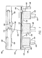
- FIG. 1 illustrates a conventional selective laser sintering system currently sold by 3D Systems, Inc. (Valencia, CA).
- a front view of the apparatus is provided with the outer covering of the apparatus cut away to show the working parts of the system.
- a carbon dioxide laser and its associated optics is shown mounted in a unit above a process chamber that includes a powder bed, two feed powder cylinders; and a leveling roller.
- the process chamber maintains the appropriate temperature and atmospheric composition for the fabrication of the built parts.
- the atmosphere is typically an inert atmosphere, such as nitrogen. It is also possible to use a vacuum in the process chamber.
- a laser beam 104 is generated by laser 108 and aimed at target surface or area 110 by way of a scanning system 114 that generally includes galvanometer-driven mirrors that deflect the laser beam 104.
- the laser and galvanometer systems are isolated from the hot process chamber 102 by a laser window 116.
- the laser window 116 is situated within radiant heater elements 120 that heat the target area 110 of the part bed below.
- the deflection and focal length of the laser beam is controlled, in combination with the modulation of the laser, to direct laser energy to those locations of the fusible powder layer corresponding to the cross-section of the article to be formed in that layer.
- Two feed systems feed powder into the system by means of push up piston systems.
- a part bed 132 receives powder from the two feed pistons (125 and 127) as described immediately hereafter.
- Feed system 126 first pushes up a measured amount of powder from the powder in feed cylinder 123 and a counter-rotating leveling roller 130 picks up and spreads the powder over the part bed 132 in a uniform manner.
- the leveling roller 130 passes completely over the target area 110 and part bed 132. Any residual powder is deposited into an overflow receptacle 136.
- Positioned nearer the top of the process chamber 102 are radiant heater elements 122 that pre-heat the feed powder.
- the laser After a traversal of the leveling roller 130 across the part bed 132, the laser selectively fuses the layer just dispensed.
- the leveling roller then returns from the area of the overflow receptacle 136, after which the feed system 124 pushes up a prescribed amount of powder from the powder in feed cylinder 129.
- the leveling roller 130 then dispenses powder over the target 110 in the opposite direction and proceeds to the other overflow receptacle 138 to deposit any residual powder.
- the center part bed piston 128 drops by the desired layer thickness to make room for additional powder.
- the feed cylinders (123 and 129) are filled with unfused powder for supply to the part-cake 106, which is formed during the build process and includes unfused powder and built parts of fused powder.
- the cylinders can take on any shape useful for powder delivery.
- the powder delivery mechanism in system 100 includes feed pistons 125 and 127, which are controlled by motors (not shown) to move upwardly and lift, when indexed, a volume of powder into chamber 102.
- Part-cake piston 128 is controlled by a motor (not shown) to move downwardly below the floor of process chamber 102 by a small amount, for example 0.125 mm, to define the thickness of each layer of powder to be processed.
- Target surface 110 refers to the top surface of heat-fusible powder (including portions previously fused, if present) disposed above part-cake piston 128; the fused and unfused powder disposed on part-cake piston 128 is shown in Figure 1 as part-cake 106.
- Radiant heaters 122 over the feed pistons pre-heat the powder to minimize any thermal shock as fresh powder is spread over the recently sintered and hot target area 110.
- This type of dual piston feed system providing fresh powder from below the target area, with heating elements for both feed beds and the part bed is implemented commercially in the VanguardTM selective laser sintering system sold by 3D Systems, Inc. (Valencia, CA).
- the above system generally describes a layerwise build process, wherein built parts are formed in the part-cake a layer at a time by laser sintering (i . e ., fusion) of the loose powder.
- the part-cake includes unfused powder and one or more built parts of fused powder.
- the built parts can be at various positions within the part-cake.
- the part-cake, at the end of the build process is in a heated state throughout, with the temperature generally being greater within the part-cake, particularly near the built parts.
- the part-cake must be allowed to cool to near ambient temperature before the built parts can be removed from the part-cake. This cooling time reduces the throughput of the system ( i .
- the external portions of the part-cake tend to cool at a quicker rate than the internal portions of the part-cake, causing undesirable thermal gradients to form within the part-cake.
- the top surface of the part-cake and the external portion of the part-cake in contact with the cylinder walls tend to cool quickly.
- the invention is not limited by the type of powder used in the laser sintering process. Any powder commonly used in laser sintering can be used according to the invention, including but not limited: plastics (such as nylons); glass-filled plastics; elastomers; polycarbonates; ceramics; metals; polystyrene; and composite materials, such as polymer metals and polymer ceramics.
- the invention provides methods for controlling the cooling rate of the part-cake by forming thermal transfer channels within the part-cake.
- the thermal transfer channels facilitate the movement of heat away from the interior portions of the part-cake.
- the channels can be, according to various embodiments, hollow ducts having substantially solid walls or substantially solid throughout. When the channels are hollow, the movement of heat can be further controlled through introducing various cooling media into the hollow channels, or ducts.
- the channels can be formed during the layerwise build process or can be formed after the build process.
- the channels can be formed prior to introduction of cooling media or can be formed simultaneously with the introduction of cooling media, particularly solid cooling media.
- the thermal transfer channels are formed in the part-cake during the laser sintering process, and the formed channels themselves are also formed by the laser sintering process.
- the thermal transfer channels are also being formed by laser sintering.
- Such channel formation is achieved through modification of the build file generation software used to direct the laser in the formation of the built parts.
- the software can be modified to include the thermal transfer channels in the same build file as the desired parts.
- the channels formed in the part-cake comprise hollow, solid-walled ducts.
- the ducts can be single-walled or multi-walled and can take on various conformations within the part-cake.
- the ducts can be angular, linear, or curvilinear.
- the dimensions of the ducts can vary, even within the same part-cake.
- the ducts can be tapered, having a wider dimension at one point in the part-cake and gradually narrowing to a narrower dimension at another point in the part-cake.
- the ducts can take on various geometries.
- the ducts can be round, oval, rectangular, triangular, or any other such geometry that can be beneficial according to the invention.
- Figure 2 provides a cross-section through a vertical plane of a part-cake after completion of a layerwise build process.
- Part-cake 106 is illustrated with built parts 210 shown distributed throughout the part-cake 106 among the unfused powder 195.
- duct 200 has been formed.
- duct 200 is formed during the layerwise building process by laser sintering. While only one duct is shown in Figure 2, it is understood that multiple ducts could be formed throughout the part-cake as beneficial for controlled cooling of the part-cake. Further, the ducts can be arranged in various, different planes throughout the part-cake.
- the duct 200 has two terminal portions (202 and 204).
- the terminal portions of the duct 200 are formed to be located at the top portion of the part-cake 106. It is beneficial for at least one terminal portion of the ducts formed within the part-cake to be located at the top portion of the part-cake for ease of removal of the unfused powder inside the ducts.
- the ducts can have one or more terminal portions within the part-cake.
- the ducts also can have one or more terminal portions at or near the walls of the cylinder 175 containing the part-cake or at or near the part-cake piston 128.
- the unfused powder has already been removed from duct 200.
- the unfused powder can be removed by vacuum suction at one terminal portion of the duct.
- at least one terminal portion of the duct can be formed to be a fitting suitable for such attachment.
- terminal portion 202 of the duct 200 is formed to be a threaded fitting 207 for attachment of a powder removal device.
- Other fitting types can be formed for use in powder removal or for other purposes, such as introducing cooling media into the ducts.
- a powder removal tool can be formed within the ducts for further removal of the unfused powder from the ducts.
- the powder removal tool is formed separate from the ducts but is formed within the ducts, by laser sintering, during the layerwise building process.
- a preferred embodiment of such a powder removal tool is illustrated in Figure 3 as a pull chain assembly 230.
- Figure 3 shows a cross-section through a vertical plane of a part-cake 106 having therein unfused powder 195, built parts 210, a duct 200, and the pull chain assembly 230 within the duct.
- the duct 200 still contains unfused powder 195 that is preferentially removed prior to introducing cooling media.
- the pull chain assembly 230 can be likened to a "beaded chain” such as can commonly be found as an on/off pull chain on hanging light fixtures or ceiling fans or as was customarily found in times past for attaching to a drain plug for a bathroom tub or sink.
- the pull chain assembly 230 can be pulled from the duct 200, breaking up the unfused powder 195 and facilitating the removal of the unfused powder 195 from the duct 200.
- the pull chain assembly 230 is illustrated in Figure 3 as a single, continuous chain or a pull line with a stripping plate or scraper attached at its terminus or a plurality of stripping plates or scrapers at spaced locations along the pull line; however other embodiments are also envisioned, such as two separate chains, each being pulled from separate terminal portions of the duct 200.
- the pull chain or pull line embodiment is also useful to remove unfused powder from any hollow channeled structure formed by laser sintering such as air ducts. They may also be used in combination with any of the embodiments shown herein in conjunction with means to facilitate cooling the part cake.
- a detailed view of the pull chain assembly 230 in the duct 200 is shown in Figure 4.
- any remaining unfused powder can be easily removed from the duct through additional means, such as by vacuum.
- the powder removal tool can be formed such that it is capable of removing substantially all of the unfused powder in the duct.
- the pull chain assembly 230 can be further formed to include scrapers 235, which are essentially disks having outer dimensions that are approximately equivalent, but slightly less than, the inner dimensions of the duct 200. As pull chain assembly 230 is removed from the duct 200, the pull chain assembly 230 breaks up the unfused powder 195, and the scrapers 235 help convey the loosened unfused powder from the duct 200.
- the powder removal tool can take on other embodiments in addition to the pull chain assembly described above, such additional embodiments also being encompassed by the invention.
- the powder removal tool can be a flexible auger.
- the auger is sufficiently flexible in bending but rigid in torsion such that rotating the shaft of the auger causes the auger to break up the powder in the duct and help to convey the loose powder out of the duct.
- the auger as with the pull chain or pull line embodiment, can be formed during the layerwise building process by laser sintering within, but separate from, the ducts.
- the auger-could be a separate tool that is introduced into the ducts after the build process. As such, the advancement of the auger through the ducts would break up the powder and assist in conveying the powder mechanically out of the ducts.
- vacuum suction could be used in conjunction with the auger, or with further mechanical powder removal embodiments.
- cooling media can be introduced into the duct for controllably cooling the part-cake 106.
- the cooling media can be gaseous media or liquid media.
- the duct 200 has two terminal portions (202 and 204), both being at the top portion of the part-cake 106. In such an embodiment, a "cooling loop" is created within the part-cake 106.
- the cooling media can be liquid or gas cooling media, being introduced at one terminal portion of the duct 200 and removed at the other terminal portion of the duct 200.
- the cooling media When a liquid is used as the cooling media, any liquid generally known as useful in thermal transfer can be used so long as the liquid is non-reactive with the duct walls (i.e., the fused powder). Further, the liquid should not be capable of solubilizing the duct walls.
- the liquid cooling media is water. According to this embodiment, various additives, such as salts, can be added to the water as would be beneficial for improving the thermal transfer action of the water.
- the liquid cooling media can be any other liquids having known heat transfer ability, including industrial coolants. Additionally, mixtures or solutions can be used as the liquid cooling media.
- the liquid cooling media can be introduced through one of terminal portions 202 and 204 of duct 200.
- the cooling media can be circulated through the duct and removed from the other terminal portion of the duct 200.
- at least one of the terminal portions (202 and 204) of the duct 200 can be formed to be a fitting 207 for attaching useful devices, such as a coolant delivery or uptake device.
- an external coolant supply and/or uptake line can be attached to the fitting 207, or other similar fitting formed on at least one of the terminal portions (202 and 204).
- the terminal portions (202 and 204) are attached to an external heat exchanger (not shown) such that temperature-controlled liquid is introduced to the duct 200 at one of the terminal portions 202 and 204, and warmed liquid is removed from the other terminal portions.
- the warmed liquid is returned to the heat exchange device where it is again cooled to a controlled temperature for return to the duct 200 for cooling the part-cake 106.
- heat transfer control at the exterior surfaces of the cylinder 175 containing the part-cake 106 can be useful for minimizing the thermal gradients that naturally occur by conduction through the cylinder to ambient surroundings and by natural or forced convection from the exterior walls of the cylinder to ambient surroundings.
- the method for controlling the cooling rate of the part-cake comprises applying heat to at least a portion of the cylinder containing the part-cake.
- the external heat is applied as one or more heater bands that can be wrapped around the cylinder at one or more locations on the cylinder.
- the heat could be supplied as a thermal blanket covering at least a portion of the cylinder, the blanket acting at an insulator alone or being capable of supplying added heat.
- the heat could be supplied from external heaters not in physical contact with the cylinder, wherein the cylinder exterior is heated through convection or radiation.
- Other methods for supplying heat to the exterior of the part-cake containing cylinder would be recognized by one of skill in the art and are also encompassed herein.
- Application of the external heat source is beneficial for coordinating the cooling rate of the external portions of the part-cake with the cooling rate of the internal portions of the part-cake.
- the heat applied can be adjusted during the cooling time such that the applied heat is slowly reduced at a controlled rate.
- the cooling rate is computer controlled such that the applied external heat is automatically reduced to correspond to the cooling rate of the internal portions of the part-cake.
- the ducts formed within the part-cake by laser sintering during the layerwise build process can be single-walled ducts, such as illustrated in Figure 2.
- the ducts can also be multi-walled (i.e., one or more ducts within a duct).
- a cross section of the ducts when the ducts have a round geometry) would appear as concentric circles.
- the formation of multi-walled ducts can be useful in various embodiments.
- the duct walls are solid, being formed of fused powder, the duct walls can be somewhat porous.
- the cooling media is a liquid media
- the unfused powder from a normal laser sintering process can be recycled and used again in further build processes: It is generally undesirable for the liquid cooling media to contact the unfused powder, as powder that has been wetted with the cooling media must either be discarded or further processed prior to further use. In one embodiment, it is useful to form multi-walled ducts to further protect against migration of liquid cooling media through the duct walls and into the unfused powder.
- Formation of multi-walled ducts can be useful in further embodiments for facilitating removal of the unfused powder from the ducts.
- Figure 5 shows a cross-section through a vertical plane of a part-cake after completion of a layerwise build process.
- a duct 200 has been formed by laser sintering during the build process.
- the duct 200 is selectively formed to be positionally related to the built parts 210 in the part-cake 106.
- the duct 200 is multi-walled, having an inner wall 221 and an outer wall 222.
- the duct 200 remains filled with unfused powder 195, the powder filling the space defined by the inner wall 221 and the space between the inner wall 221 and the outer wall 222.
- the outer wall 222 of the duct 200 is continuous throughout the part-cake 106 having a V-shape and having two terminal portions 202 and 204 at the top portion of the part-cake 106.
- the inner wall 221 of the duct 200 is sealed and forms a closed terminal point for the inner wall 221 near the bottom most point of the duct 200 in the part-cake 106.
- This arrangement of the inner wall 221 can be seen more clearly in Figure 6, which provides an enlarged view of the lower portion of the duct 200 in the part-cake 106.
- the multi-walled duct shown in Figures 5 and 6 can generally be viewed as a "core and cavity" type arrangement.
- the inner wall 221 forms a "core" 225 of unfused powder encased in a solid wall 221 formed of fused powder.
- the core 225 can be pulled from the part-cake 106 as a single unit leaving an open "cavity" 226 defined by the outer wall 222 of the duct 200. Again, this is more easily seen in Figure 6, wherein the core 225 on the right side of the part-cake 106 has been partially removed leaving behind the cavity 226, which is open and ready for introduction of cooling media. Likewise, the core 225 on the left side of the part-cake 106 is also removed.
- the duct 200 is tapered, being narrowed near the bottom portion of the part-cake 106 and becoming widened toward the top portion of the part-cake 106. Such tapering of the duct 200 is particularly beneficial for aiding in removal of the core 225 as a single unit.
- the duct is formed as a multi-wall duct (i.e., a duct within a duct)
- removal of the core leaves a final duct that is single-walled.
- the original multi-walled duct can be formed of three or more concentric ducts with the inner wall still defining a core for later removal. The subsequent removal of the core would leave behind a cavity as described above, but the final duct would remain a multi-wall duct throughout the part-cake.
- inner wall 221 and outer wall 222 are formed to be in close relation to one another but not physically connected. Forming the walls close together leaves less unfused powder 195 between the walls. After removal of the core 225, a small amount of unfused powder 195 can remain in the cavity 226. Such powder may be small enough in volume that leaving the powder in the cavity 226 will not interfere with the introduction of the cooling media. Alternately, if desired, the remaining unfused powder 195 can be removed from the cavity, such as through vacuum suction, and recycled for later use. Similarly, the unfused powder 195 in the core 225 can be recycled.
- the inner wall 221 is formed to be as thin as functionally possible to reduce the amount of powder used in forming the wall and minimize the amount of waste in the process.
- the walls of the ducts according to the invention have a thickness of about 0.1 mm to about 10 mm, more preferably about 0.25 mm to about 5 mm, most preferably about 0.5 mm to about 1 mm.
- the cooling media introduced into the ducts can be gaseous or liquid.
- the ducts are formed as shown in Figures 5 and 6 and liquid cooling media is introduced into the ducts.
- the liquid can be circulated through the ducts, being introduced at one terminal portion of the duct and removed at a second terminal portion of the duct.
- the ducts of the invention have sufficient structure to resist the compressive forces of the surrounding part-cake and remain open. This is generally not a great concern when liquid cooling media is used, as the duct walls are of sufficient thickness to prevent migration of liquid through the walls.
- the ducts When the ducts are filled with liquid, the ducts have the additional structural support provided by the liquid.
- ducts are formed in the part-cake, and pressurized gas is pumped through the ducts, the gas migrating out of the duct, through the part-cake, and back to the atmosphere at the top portion of the part-cake.
- the duct walls must still have sufficient structure to resist the compressive forces of the surrounding part-cake and remain open, the walls must be porous enough to allow air, or other temperature-controlled gas, to be pumped at slight pressure through the ducts and into the part-cake.
- porosity can be inherent to the duct walls formed of fused powder.
- the duct walls could be purposely formed with openings in the walls sufficient for allowing pressurized gas to migrate out of the duct into the part-cake while disallowing unfused powder from the part-cake to move into the duct.
- FIG. 7 provides a cross-section through a vertical plane of a part-cake 106 within a cylinder 175 after a completed build process.
- the part-cake 106 includes unfused powder 195 and built parts 210 formed during a layerwise build process.
- ducts 200 are formed during the layerwise build process.
- the duct 200 on the left side of the part-cake 106 is shown as formed, with unfused powder 195 remaining in the duct area defined by the duct walls.
- the duct 200 on the right side of the part-cake 106 has had the unfused powder removed from the duct, preferably using a method as described herein.
- the ducts 200 shown in Figure 7 are vertical and straight, each duct having one open terminal portion at the top portion of the part-cake 106 and one closed terminal portion within the part-cake 106.
- Other duct geometries and orientations are also encompassed by the invention.
- the ducts could be formed diagonally or could be angular or substantially curvilinear.
- straight ducts are preferred for ease of removal of the unfused powder within the ducts.
- a powder removal tool could be formed within the duct to aid in removal of the unfused powder.
- the tops of the ducts 200 are preferentially formed for easy attachment to a gas delivery source.
- the tops of the ducts are sealed ( i . e ., air-tight) disallowing escape of temperature controlled gas introduced into the ducts. Accordingly, the only exit for the gas from the ducts is through the porous walls and into the part-cake.
- the tops of the ducts could be formed to be threaded or formed to have a "quick-connect" type structure.
- the duct 200 on the right side of the part-cake 106 is shown with the unfused powder removed from the top portion of the duct 200 and a gas delivery attachment 250 connected thereto.
- the gas delivery attachment 250 seals the originally open top of the duct 200 against the pressure of the gaseous cooling media later introduced.
- a return portal for the introduced gas is unnecessary as the return path for the pressurized gas is to flow through the porous walls of the duct 200, through the unfused powder 195 in the part-cake 106, and to the atmosphere at the open, top portion of the part-cake 106.
- Such flow is exemplified in Figure 7 by the wavy arrows.
- the gaseous media migrating through the unfused powder 195 and around the built parts 210, aids in the transference of heat away from the interior of the part-cake 106 to the atmosphere.
- the gaseous cooling media is at ambient temperature.
- the gaseous cooling media is cooled in a temperature controlled fashion below ambient temperature prior to introduction to the ducts 200.
- Such embodiments are particularly useful when the built parts 210 in the part-cake are robust (i.e., are of substantial structure, such as being solid throughout or having all parts being of substantial thickness).
- the built parts 210 are less robust (i.e., particularly small, intricate, or thin-walled parts)
- gaseous media such as atmospheric air
- the gaseous media comprises an inert gas, such as nitrogen gas.
- an inert gas as the gaseous cooling media is particularly preferred as oxidation, or other similar chemical reactions, might occur with the introduction of a more reactive gas, such as oxygen-containing atmospheric air, into the warm part-cake.
- the gaseous media introduced into the ducts in the embodiments of the invention as illustrated in Figure 7 is preferentially pressurized.
- the pressure is generally kept low enough so as to allow for slow movement of the gaseous media through the unfused powder in the part-cake without over-fluidizing the powder. Using a pressure that is too great can lead to cooling of the part-cake that is too rapid, which can also lead to unfavorable thermal gradients within the part-cake.
- the pressure is also kept low to avoid disrupting the integrity of the part-cake, blowing unfused powder up out of the part-cake and into the atmosphere. Such extreme pressure could also lead to damage to the built parts.
- the pressure of the gaseous media introduced into the ducts is any positive pressure sufficient to force migration of the gas from the duct into the part-cake yet remaining within the above-noted limitations.
- the ducts used in cooling the part-cake can be straight, as illustrated in Figure 7, but be formed for introduction of liquid cooling media.
- Figure 8 One such embodiment is illustrated in Figure 8, wherein there is shown a cross-section through a vertical plane of a part-cake having a cooling duct formed therein.
- the part-cake 106 is contained in cylinder 175 and includes built parts 210 and unfused powder 195. Also included is duct 200, which is preferentially formed during the layerwise build process.
- the duct 200 is straight and, preferentially, tapered.
- the duct 200 is multi-walled, having an inner wall 221, and an outer wall 222. While such construction is preferred, particularly when introducing liquid cooling media, the duct 200 could also be of single-wall construction.
- the outer wall 222 can comprise two or more walls.
- the duct 200 has an open, upper terminal portion at the upper portion of the part-cake 106 and a closed, lower terminal portion within the part-cake 106.
- the unfused powder has been removed from the area of the duct defined by the inner wall 221.
- This area defined by the inner wall 221 essentially forms a reservoir 270 within the duct 200.
- an annular space 275 exists between the inner wall 221 and the outer wall 222.
- the liquid cooling media can be introduced into the reservoir 270 for drawing heat away from the part-cake 106 and into the cooling media.
- a temperature-controlled liquid is introduced into the reservoir 270, and the fluid is circulated within the reservoir 270. While only a single reservoir is illustrated in Figure 8 and described herein, it is understood that the invention further encompasses methods wherein multiple reservoirs are formed in the part-cake 106.
- the temperature-controlled liquid can be circulated within the reservoir 270 with the aid of an external heat exchange device (not shown), such as a refrigerated pump system.
- the temperature-controlled liquid media could be pumped into the reservoir 270 through a supply line 260 and pumped out of the reservoir 270 through a return line 262.
- the supply line 260 is situated near the bottom of the reservoir 270 and the return line 262 is situated near the top of the reservoir 270.
- the reservoir 270 can be initially filled with the liquid cooling media, with the external circulation system delivering a constant flow of temperature-controlled liquid to the bottom the reservoir 270 and removing fluid from the top of the reservoir that has been warmed through heat exchange with the inner wall 221 of the duct 200, drawing heat from the part-cake 106.
- Such circulation of the liquid cooling media is illustrated in Figure 8 with the arrows showing movement of the liquid in the reservoir 270.
- the supply line 260 and the return line 262 could be placed at varying depths in the reservoir 270 as would be recognized by one of skill in the art as being beneficial for efficiently removing heat from the part-cake in a useful, controlled manner.
- the duct 200 with the reservoir 270 formed therein essentially spans the part-cake 106 vertically from top to bottom, thereby removing heat from a greater proportion of the part-cake 106.
- the reservoirs formed in the part-cake could terminate at varying depths within the part-cake depending upon the thermal environment desired to be produced at different locations throughout the part-cake.
- the reservoirs can take on varying shapes and orientations and need not necessarily be straight or strictly vertical.
- the reservoirs can be of any shape and orientation within the part-cake.
- the ducts formed for use as reservoirs for liquid cooling media can be single-wall ducts, as this reduces the volume of unfused powder used in the cooling method that must be discarded as waste.
- the duct walls may not have sufficient integrity to completely prevent migration of liquid cooling media through the duct walls. If such migration occurs, the unfused powder around the duct walls could be wetted by the liquid, require disposal of the powder or further processing of the powder prior to reuse. Accordingly, in some embodiments, it can be beneficial to form multi-wall ducts, such as the dual-wall duct illustrated in Figure 8. As shown in Figure 8, while the unfused powder is removed from the area defined by the inner wall to leave a reservoir therein, unfused powder remains in the annular space(s) between the inner wall and the one or more outer walls.
- Figure 9 provides a detailed view of a portion of the duct and part-cake from Figure 8.
- the annular space 275 between the inner wall 221 and the outer wall 222 remains filled with unfused powder 195.
- Any liquid cooling media migrating from the reservoir 270 through the inner wall 221 becomes trapped in the annular space 275 and does not proceed to migrate through the outer wall 222 and into the remaining unfused powder 195 in the part-cake 106.
- the liquid is absorbed by the unfused powder in the annular space 275, wicking through the dry powder and evaporating to the atmosphere out the top portion of the annular space 275 at the top portion of the part-cake 106.
- This multi-wall/powder-filled annular space combination provides protection to the unfused powder 195 in the remaining portion of the part-cake 106 and also provides an additional cooling effect through the wicking and evaporation action.
- Figure 10 illustrates additional embodiments of the invention using ducts/reservoirs to contain liquid cooling media.
- Figure 10 is similar to Figure 9 in providing a cross-section through a vertical plane of a part-cake 106 and the contents thereof following a layerwise build process.
- the duct 200 formed in the layerwise build process can be a single-wall duct having an open top terminal portion and a closed bottom terminal portion, the walls thereof forming a reservoir 270 for containing liquid cooling media.
- the reservoir 270 illustrates one of the additional various shapes possible with the formed ducts of the invention.
- a tray or catch basin 290 can be formed.
- the catch basin 290 seals off the top layer of unfused powder 195 in the part-cake 106 and is integrally connected to the top of the duct 200.
- the catch basin 290 can cover only a portion of the top of the part-cake 106 in the area around the top of the duct 200, leaving open to the atmosphere at least part of the top portion of the part-cake 106. If desired, the catch basin 290 can cover the entire top surface of the part-cake 106.
- the catch basin 290 protects the underlying unfused powder 195 from any liquid cooling media escaping from the reservoir 270 due to splashing or due to the flow/pumping action associated with the use of an external pumping device as described above.
- the ducts comprising the thermal transfer channels can be formed by laser sintering during the layerwise build process. Such formation is particularly beneficial in that the ducts can be formed to any shape, size, conformation, or position useful for controllably cooling the part-cake and the components contained therein.
- the ducts are formed during the layerwise build process, and after the build process is complete, the unfused powder is removed from the ducts and the cooling media is introduced.
- the ducts have only one opening (generally at the top portion of the part-cake) for introducing and removing the cooling media.
- the ducts have two or more openings at the top portion of the part-cake, wherein cooling media can be introduced at one opening and removed at another opening (providing a flow-through system).
- the ducts can have two or more openings forming a flow-through system, wherein at least one opening is within the part cake, preferentially being at or near the sidewalls of the cylinder containing the part-cake or the piston forming the bottom of the cylinder.
- Figure 11 provides a cross-section through a vertical plane of a part-cake 106 contained within a cylinder 175 defined by cylinder sidewalls 177 and piston 128. Contained within the part-cake 106 are unfused powder 195 and built parts 210.
- the part cake cylinder apparatus used in the layerwise build process is particularly characterized by the presence of permanent fittings 350 in the cylinder sidewalls 177 and the piston 128.
- Such fittings can be strategically placed at various locations in the sidewalls, 177, the piston 128, or both, preferentially being at spatial positions identified in the build software used to form the ducts.
- the fittings 350 are preferably standardized for being easily connected to tubing or other attachments useful for removing unfused powder 195 from the ducts 200 or introducing cooling media into the ducts 200.
- the fittings 350 can take on various types, shapes, and structures, all of which are encompassed by the invention.
- the ducts 200 can be formed during the layerwise build process to have at least one terminal portion in alignment with a permanent fitting 350.
- the ducts 200 are formed to have one terminal portion in alignment with a fitting 350 and one terminal portion at the top portion of the part-cake 106.
- the fitting 350 could be in the cylinder sidewall 177 or the piston 128.
- the ducts 200 are formed to have one terminal portion in alignment with one fitting 350 and one terminal portion in alignment with another fitting 350.
- the ducts 200 can take on multiple conformations being, for example, straight and vertical or curvilinear.
- the ducts 200 are formed to be at least partially conformal with the built parts 210.
- the ducts 200 also could be straight and horizontal being formed between two fittings 350 in the cylinder sidewalls 177 on opposite sides of the cylinder 175.
- the ducts can be cleared of unfused powder 195 to prepare for introduction of cooling media.
- the fittings 350 can comprise caps or other means for preventing unfused powder from entering the fitting 350 prematurely.
- the ducts 200 also can be formed to have a solidified portion immediately adjacent the fitting 350. Once the build process is complete, the cap can be removed or the solidified portion at the end of the duct 200 can be broken away to allow access to the unfused powder 195 in the ducts 200. The unfused powder 195 can then be removed, such as through vacuum suction.
- the unfused powder 195 can be removed through application of vacuum suction at one fitting 350 and application of pressurized gas at the other fitting 350.
- Methods of powder removal as described in relation to additional embodiments herein also can be used according to the embodiment.
- a powder removal tool can be formed within the ducts to aid in breaking up the powder and removing it from the ducts.
- the cooling media introduced can vary depending upon the desired cooling rate and the structure of the ducts formed in the part-cake.
- the temperature-controlled cooling media is preferentially gaseous media or liquid media.
- the thermal transfer channels can be formed after completion of the layerwise build process used to form the built parts in the part-cake.
- the thermal transfer channels are formed simultaneously with the introduction of the solid cooling media.
- Figure 12 shows a cross-section through a vertical plane of a part-cake 106 having therein unfused powder 195 and built parts 210.
- the figure further shows solid cooling media (305 and 307) introduced to the part-cake 106.
- the solid cooling media ( 305 and 307 ) are pushed into the unfused powder - 195 in the part-cake 106, with care given to avoid direct contact with the built parts 210.
- the mechanical force used to introduce the solid cooling media ( 305 and 307 ) into the part-cake 106 forms the channels for containing the solid cooling media (305 and 307) by displacing the unfused powder 195.
- Figure 12 illustrates an embodiment wherein thermal transfer channels have been formed in the part-cake 106 simultaneously with the introduction of solid cooling media (305 and 307).
- the solid cooling media (305 and 307), and the thermal transfer channels formed by the introduction of the solid cooling media (305 and 307) into the part-cake 106 can be of varying depths, so long as at least a portion of the solid cooling media (305 and 307) is introduced into the part-cake 106. It is not necessary for the solid cooling media and the thermal transfer channels to be vertically disposed.
- the solid cooling media comprises a heat pipe 305.
- a heat pipe is a generic term used to describe devices that can quickly transfer heat from one point to another.
- Heat pipes generally consist of a sealed container, a working fluid within the container, and a wick or capillary structure within the container. Heat pipes can effectively transport heat against gravity by an evaporation-condensation cycle with the help of porous capillaries that form the wick.
- the wick provides the capillary driving force to return condensate to an evaporator. The quality and type of wick usually determines the performance of the heat pipe.
- the solid cooling media comprises a thermally conductive probe 307.
- a thermally conductive probe is generally simpler in construction than a heat pipe, often simply comprising a metal tube or rod.
- the metal has a high thermal conductance, such as copper or aluminum.
- the thermally conductive probe 307 can be connected to an external heat exchange device, such as a temperature-controlled active cooling system.
- thermal energy is conducted from the warmer portions of the part-cake 106 to the cooler thermally conductive probe 307 or heat pipe 305.
- the heat is then conducted from the thermally conductive probe 307 to the atmosphere or dissipated in the internal heat exchange system of the heat pipe 305.
- the thermally conductive - probe 307 is connected to a temperature-controlled active cooling system, the heat is conducted from the probe 307 to the cooling system.
- the thermal transfer channels can themselves be at least partially solid.
- the introduction of cooling media is not required, as the solid thermal transfer channels function to facilitate the movement of heat out of the part-cake, generally out to the atmosphere.
- Figure 13 wherein there is shown a cross-section through a vertical plane of a part-cake 106 contained in a cylinder 175 and having therein unfused powder 195 and built parts 210 formed during a layerwise build process.
- the thermal transfer channels are present as cooling fins 325.
- the cooling fins comprise fused powder and are formed by laser sintering in the layerwise build process.
- Cooling fins 325 can be generated automatically by software, or manually added to the build file, at desired locations in the part-cake 106 relative to the built parts 210. During the building process, the cooling fins 325 can be built in close relation to specific areas of the part-cake 106, such as around the built parts 210, where increased cool down is desired. The cooling fins 325 provide paths of increased thermal conduction and can be formed to continue from the areas where increased cool down is desired up to the surface of the part-cake.
- the cooling fins 325 are at least partially conformal in nature, being shaped to at least partially conform to the shape of one or more of the built parts 210 in the part-cake 106.
- the terminal portions of the cooling fins at the top portion of the part-cake 106 can be physically connected to relatively cooler thermal sinks (not shown), which draw thermal energy out of the part-cake 106, in particular from the desired specific areas in need of increased cool down.
- the cooling fins 325 can take on various forms.
- the cooling fin can comprise a single continuous piece of fused powder in taking on various combinations of angled, linear, and curvilinear formations.
- the cooling fin can comprise a branched structure with a main body with one or more branches extending therefrom throughout the part-cake.
- Other advantageous conformations could be envisioned by one of skill in the art and are also encompassed by the invention.
- the thermal transfer channels comprise ducts that are formed in the part-cake after the layerwise build process is completed.
- the ducts can advantageously be formed during the layerwise build process through laser sintering.
- the ducts can be formed by digging paths through the unfused powder in the part-cake and inserting pre-made components, such as flexible tubing, into the dug paths.
- a "directional drilling" system can be used to steer a boring head, or drill bit, through the part-cake.
- a boring head or drill bit
- unfused powder is removed leaving an open path through the part-cake.
- a solid, flexible tube (or other duct-like apparatus) can be inserted in the path.
- the boring head while boring out the path, simultaneously pulls the tubing behind, immediately filling the bored out path with the tube, thereby forming a duct-like thermal transfer channel throughout the part-cake.
- the boring system is computer controlled through programming capable of monitoring the bore head's position in three-dimensional space within the part-cake and steering the bore head through the part-cake to form the ducts near and around the built parts without damaging the parts.
- cooling media can be introduced into the ducts for facilitating cooling of the part-cake.
- thermal transfer channels within the part-cake is beneficially performed under computer control.
- the thermal transfer channels are ducts formed of fused powder
- the placement of the ducts can be mapped in relation to the built parts to be formed in the build process.
- the ducts are made part of the build file and are generated automatically during the build process.
- the thermal transfer channels are cooling fins
- the placement of the fins can be mapped in relation to the build parts and made part of the build file to be formed automatically during the build process.
- a computer is beneficially used to interpret the build file to map the location of the built parts within the part-cake.
- the computer can guide the bore head through the part-cake avoiding the built parts while forming the thermal transfer channels in advantageous proximity to the built parts for controlling the cooling of the part-cake.
- placement of thermal transfer channels throughout the part-cake can be automatically generated by a combination of the normal build-file generation software with additional analytical software, such as thermal analysis software or computational fluid dynamics software.
- additional analytical software such as thermal analysis software or computational fluid dynamics software.
- Such combination can advantageously place the thermal transfer channels in optimized positions and routings throughout the part-cake.
- the optimized positions and routings are particularly beneficial for minimizing geometric distortions of the built parts and maximizing the cooling rate of the part-cake.
- the laser sintering system according to the invention exhibits reduced process time and increased throughput without having adversely affected built part geometry or accuracy.
Landscapes
- Engineering & Computer Science (AREA)
- Chemical & Material Sciences (AREA)
- Manufacturing & Machinery (AREA)
- Materials Engineering (AREA)
- Physics & Mathematics (AREA)
- Mechanical Engineering (AREA)
- Optics & Photonics (AREA)
- Oral & Maxillofacial Surgery (AREA)
- Thermal Sciences (AREA)
- Life Sciences & Earth Sciences (AREA)
- Sustainable Development (AREA)
- Health & Medical Sciences (AREA)
- Plasma & Fusion (AREA)
- Powder Metallurgy (AREA)
Abstract
Description
- The invention is directed to a method and apparatus for controlling the cooling rate of a part-cake in a laser sintering apparatus, the part-cake containing unfused powder and built parts of fused powder.
- Solid freeform fabrication processes are increasingly used for producing freeform, complex geometry components. In particular, selective laser sintering is useful for creating three dimensional objects directly from digital data (e.g., computer-aided-design (CAD) databases, medical scan imaging files, etc.) in an automated fashion. An object is created through a sequential fusion buildup of cross sections of the finished part from a starting powder. The powder is fused with a scanning laser beam one layer at a time, and each scanned layer corresponds to a cross section of the final object's mathematically sectioned digital data model.
- Detailed descriptions of selective laser sintering technology are provided in U.S. Patent Nos. 4,863,538; 4,944,817; and 5,132,143, all assigned to the Board of Regents, The University of Texas System, and in U.S. Patent No. 4,247,508 to Housholder.
- Laser sintering is a thermally based process. The sources of thermal energy are typically heaters for the part bed, cylinder, and heaters to preheat the powder in powder feed cylinders, and the laser. The laser is typically a CO2 laser that scans the fresh powder layer to selectively fuse powder particles in the desired areas. The powder is normally kept near the fusion temperature of the particular powder so that the added heat required by the laser to fuse the part is minimized and thermal gradients during building are minimized. The part-cake (essentially comprising a block of fused and unfused powder) remaining after the completed layerwise build process is hot.
- Before the laser sintering process can be restarted to build a new part or series of parts, the part-cake is cooled down to a handling temperature safe for the personnel handling the apparatus and acceptable for removing the built parts without damage to the parts. Powder materials commonly used in laser sintering have comparatively poor thermal conductivity and so can take a long time to cool down to workable temperatures, particularly at the interior portions of the part-cake. The time required for cool down of the part-cake is further increased as larger build areas are used (i.e., one or more of the X, Y, or Z dimensions of the part cake is increased). The increased cool-down time reduces efficiency of the laser sintering process by increasing the residence time for each part build session, thereby decreasing throughput of the laser sintering system.
- The cool down portion of the laser sintering process can be detrimental to the built parts if the cooling is non-uniform throughout the part-cake, causing uncontrolled thermal gradients therein. Non-uniform cooling can lead to unacceptable geometric distortions of the built parts in the part-cake, as well as inconsistent mechanical properties of the built parts.
- In one aspect of the invention, there is provided a method for controlling the cooling rate of at least a portion of a part-cake in a laser sintering system, the part-cake including unfused powder and one or more built parts of fused powder. In one embodiment of this aspect of the invention, the method comprises selectively forming one or more thermal transfer channels in at least a portion of the part-cake. The thermal transfer channels can comprise solid-walled ducts. The ducts can be formed by laser sintering during a layerwise build process. Alternately, the ducts can be inserted after the build process through tunneling methods. The ducts also can be formed after the build process at the time of insertion of a solid cooling media. For example, the channels could be formed by inserting a solid thermally conductive probe into the unfused powder in the part-cake. The thermal transfer channels can also comprise materials that are essentially solid throughout. In one preferred embodiment, the thermal transfer channels comprise solid cooling fins of fused powder, the fins being formed by laser sintering during the layerwise build process.
- In another embodiment, the method of the invention comprises forming, by laser sintering, one or more ducts in at least a portion of the part-cake during a layerwise build process. The method further comprises removing unfused powder from the ducts, and introducing cooling media into the ducts. The ducts can be single-walled or multi-walled, with each duct preferably having two terminal portions at the open, top surface of the part-cake. In a particularly preferred embodiment, a powder removal tool is formed within the ducts by laser sintering during the layerwise build process. The powder removal tool can take on various forms beneficial for aiding in removal of unfused powder from the ducts to facilitate cooling.
- According to another embodiment of the invention, the method comprises forming one or more multi-walled ducts in at least a portion of the part-cake by laser sintering during a layerwise build process. Preferentially, the multi-walled ducts comprise an inner wall and one or more outer walls, wherein the inner wall defines a core of unfused powder within the outer walls. The method further comprises removing the core of unfused powder and introducing cooling media into the remaining ducts formed by the outer walls. In a particularly preferred embodiment, two ducts are formed, each being open at the top surface of the part-cake and extending diagonally downward into the part-cake, the two ducts meeting at a point within the part-cake. According to this embodiment, removal of the cores formed in each of the two ducts results in formation of a single continuous duct that is substantially V-shaped.
- In still another embodiment of the invention, the method comprises forming one or more ducts in at least a portion of a part-cake by laser sintering during a layerwise build process, wherein the ducts have open terminal portions at the top portion of the part-cake and closed terminal portions within the part-cake. The method further comprises removing unfused powder from the ducts and introducing cooling media into the ducts. In one particular embodiment, the cooling media is a gaseous media. According to this embodiment, the formed ducts are preferentially at least semi gas-permeable. Further, preferentially, the open terminal portions are sealed after formation or installation of gas supply fittings. The gaseous cooling media can then be introduced into the duct under pressure sufficient to facilitate migration of the gaseous cooling media out of the ducts, through the unfused powder and around the built parts in the part-cake, and out to the atmosphere through the portion of the part-cake open to the atmosphere. In another particular embodiment, the cooling media is a liquid cooling media. According to this embodiment, the ducts are essentially reservoirs, preferentially liquid tight, for the cooling liquid. The liquid can be re-circulated in the reservoir through use of an external re-circulating apparatus, which preferably also functions as a heat exchange apparatus, removing warmed liquid from the reservoir and returning cooled liquid to be circulated therein. It is beneficial, according to this embodiment, for the formed ducts to be multi-walled, the unfused powder being removed from the space defined by an inner wall, but the unfused powder being left in the annular space between the inner wall and one or more outer walls.
- According to another embodiment of the invention, there is provided a method for controlling the cooling rate of at least a portion of a part-cake having therein unfused powder and one or more built parts, the method comprising selectively forming one or more cooling fins comprising fused powder in at least a portion of the part-cake. Preferentially, the cooling fins are at least partially conformal with the built parts within the part-cake, being selectively positioned for effectively transferring heat away from the parts to the top surface of the part-cake. In one particular embodiment, the ends of the cooling fins at the top surface of the part-cake are attached to an external heat exchange apparatus for further heat removal.
- According to still another embodiment of the invention, there is provided a method for controlling the cooling rate of at least a portion of a part-cake having therein unfused powder and one or more built parts, the method comprising forming one or more thermal transfer channels in at least a portion of the part-cake by inserting at least a portion of one or more solid cooling media into the part-cake. The solid cooling media can include any solid material generally known to be thermally conductive, such as thermally conductive probes. In one particular embodiment, the ends of the solid cooling media at the top surface of the part-cake are attached to an external heat exchange apparatus for further heat removal.
- According to another aspect of the invention, there is provided a part cake cylinder that may be positioned in the laser sintering system or removable therefrom. In one embodiment, the cylinder apparatus comprises a part-cake containing cylinder having sidewalls, an open top, and a bottom defined by a piston. The cylinder comprises one or more fittings for receiving the terminal portion of a cooling duct formed in the part-cake during a layerwise building process. In one particular embodiment, the fittings are in the sidewalls of the cylinder. In another particular embodiment, the fittings are in the piston.
- According to yet another aspect of the invention, there is provided a part-cake from a laser sintering process, wherein the part-cake comprises one or more thermal cooling channels. In one preferred embodiment, the thermal cooling channels include ducts, which can be single-walled or multi-walled. In another preferred embodiment, the thermal cooling channels include cooling fins. Preferentially, the cooling fins are at least partially conformal to one or more built parts within the part-cake.
- Having thus described the invention in general terms, reference will now be made to the accompanying drawings, wherein:
- FIGURE 1 is a diagrammatic front elevational view of a conventional selective laser sintering machine showing some of the mechanisms of the system;
- FIGURE 2 is cross-section through a vertical plane of a part-cake after a completed layerwise build process illustrating one embodiment of the invention wherein ducts have been formed in the part-cake and have been evacuated of unfused powder;
- FIGURE 3 is a cross-section through a vertical plane of a part-cake wherein the ducts remain filled with unfused powder and where the ducts have formed therein a powder removal device;
- FIGURE 4 is a detailed view of a portion of the duct from Figure 3;
- FIGURE 5 is a cross-section through a vertical plane of a further embodiment of the invention wherein multi-walled ducts have been formed in the part-cake in a "core and cavity" system;
- FIGURE 6 is a detailed view of the bottom portion of the multi-wall ducts illustrated in Figure 5 with the right-hand "core" shown partially removed;
- FIGURE 7 is a cross-section through a vertical plane of an embodiment of the invention wherein gaseous cooling media is used to cool the part-cake by being pumped into the part-cake through a porous duct;
- FIGURE 8 is a cross-section through a vertical plane of another embodiment of the invention wherein a multi-walled duct has been formed as a liquid cooling media reservoir;
- FIGURE 9 is a detailed view of a portion of the multi-wall duct of Figure 8 particularly illustrating the annular space between the walls;
- FIGURE 10 is a cross-section through a vertical plane of a part-cake with a cooling system of another embodiment of the invention, particularly illustrating the use of alternate duct/reservoir formations and the use of a catch basin for protecting the unfused powder from liquid cooling media;
- FIGURE 11 is a cross-section through a vertical plane of a part-cake in a containing cylinder with permanent fittings in the cylinder sidewall and piston for connecting to the ducts formed within the part-cake;
- FIGURE 12 is a cross-section through a vertical plane of a part-cake wherein the thermal transfer channels are formed by the introduction of solid cooling media into the part-cake; and
- FIGURE 13 is a cross-section through a vertical plane of a part-cake wherein the thermal transfer channels are conformal cooling fins formed during the layerwise build process.
- The invention now will be described more fully hereinafter with reference to the accompanying drawings, in which preferred embodiments of the invention are shown. These embodiments are provided so that this disclosure will be thorough and complete, and will fully convey the scope of the invention to those skilled in the art.
- The invention is directed to methods and apparatus for selectively controlling the cooling rate of a part-cake in a laser sintering process. Figure 1 illustrates a conventional selective laser sintering system currently sold by 3D Systems, Inc. (Valencia, CA). In Figure 1, a front view of the apparatus is provided with the outer covering of the apparatus cut away to show the working parts of the system. Generally, a carbon dioxide laser and its associated optics is shown mounted in a unit above a process chamber that includes a powder bed, two feed powder cylinders; and a leveling roller. The process chamber maintains the appropriate temperature and atmospheric composition for the fabrication of the built parts. The atmosphere is typically an inert atmosphere, such as nitrogen. It is also possible to use a vacuum in the process chamber.
- More specifically, in
laser sintering system 100, alaser beam 104 is generated bylaser 108 and aimed at target surface orarea 110 by way of ascanning system 114 that generally includes galvanometer-driven mirrors that deflect thelaser beam 104. The laser and galvanometer systems are isolated from thehot process chamber 102 by alaser window 116. Thelaser window 116 is situated withinradiant heater elements 120 that heat thetarget area 110 of the part bed below. The deflection and focal length of the laser beam is controlled, in combination with the modulation of the laser, to direct laser energy to those locations of the fusible powder layer corresponding to the cross-section of the article to be formed in that layer. - Two feed systems (124 and 126) feed powder into the system by means of push up piston systems. A
part bed 132 receives powder from the two feed pistons (125 and 127) as described immediately hereafter.Feed system 126 first pushes up a measured amount of powder from the powder infeed cylinder 123 and acounter-rotating leveling roller 130 picks up and spreads the powder over thepart bed 132 in a uniform manner. The levelingroller 130 passes completely over thetarget area 110 andpart bed 132. Any residual powder is deposited into anoverflow receptacle 136. Positioned nearer the top of theprocess chamber 102 areradiant heater elements 122 that pre-heat the feed powder. After a traversal of the levelingroller 130 across thepart bed 132, the laser selectively fuses the layer just dispensed. The leveling roller then returns from the area of theoverflow receptacle 136, after which thefeed system 124 pushes up a prescribed amount of powder from the powder infeed cylinder 129. The levelingroller 130 then dispenses powder over thetarget 110 in the opposite direction and proceeds to theother overflow receptacle 138 to deposit any residual powder. Before the levelingroller 130 begins each traverse of the system the centerpart bed piston 128 drops by the desired layer thickness to make room for additional powder. When the build process begins, the feed cylinders (123 and 129) are filled with unfused powder for supply to the part-cake 106, which is formed during the build process and includes unfused powder and built parts of fused powder. The cylinders can take on any shape useful for powder delivery. - The powder delivery mechanism in
system 100 includesfeed pistons chamber 102. Part-cake piston 128 is controlled by a motor (not shown) to move downwardly below the floor ofprocess chamber 102 by a small amount, for example 0.125 mm, to define the thickness of each layer of powder to be processed.Target surface 110 refers to the top surface of heat-fusible powder (including portions previously fused, if present) disposed above part-cake piston 128; the fused and unfused powder disposed on part-cake piston 128 is shown in Figure 1 as part-cake 106.Radiant heaters 122 over the feed pistons pre-heat the powder to minimize any thermal shock as fresh powder is spread over the recently sintered andhot target area 110. This type of dual piston feed system, providing fresh powder from below the target area, with heating elements for both feed beds and the part bed is implemented commercially in the Vanguard™ selective laser sintering system sold by 3D Systems, Inc. (Valencia, CA). - The above system generally describes a layerwise build process, wherein built parts are formed in the part-cake a layer at a time by laser sintering (i.e., fusion) of the loose powder. Upon completion of the build process, the part-cake includes unfused powder and one or more built parts of fused powder. The built parts can be at various positions within the part-cake. As previously noted, the part-cake, at the end of the build process, is in a heated state throughout, with the temperature generally being greater within the part-cake, particularly near the built parts. The part-cake must be allowed to cool to near ambient temperature before the built parts can be removed from the part-cake. This cooling time reduces the throughput of the system (i.e., reduces the net number of build processes that can be performed in a given time). The external portions of the part-cake tend to cool at a quicker rate than the internal portions of the part-cake, causing undesirable thermal gradients to form within the part-cake. For example, the top surface of the part-cake and the external portion of the part-cake in contact with the cylinder walls tend to cool quickly. These thermal gradients can lead to geometric distortions and inconsistent material properties in the built parts.
- The invention is not limited by the type of powder used in the laser sintering process. Any powder commonly used in laser sintering can be used according to the invention, including but not limited: plastics (such as nylons); glass-filled plastics; elastomers; polycarbonates; ceramics; metals; polystyrene; and composite materials, such as polymer metals and polymer ceramics.
- The invention provides methods for controlling the cooling rate of the part-cake by forming thermal transfer channels within the part-cake. The thermal transfer channels facilitate the movement of heat away from the interior portions of the part-cake. The channels can be, according to various embodiments, hollow ducts having substantially solid walls or substantially solid throughout. When the channels are hollow, the movement of heat can be further controlled through introducing various cooling media into the hollow channels, or ducts. The channels can be formed during the layerwise build process or can be formed after the build process. The channels can be formed prior to introduction of cooling media or can be formed simultaneously with the introduction of cooling media, particularly solid cooling media.
- In one embodiment of the invention, the thermal transfer channels are formed in the part-cake during the laser sintering process, and the formed channels themselves are also formed by the laser sintering process. In other words, while the built parts are being formed in the layerwise build process through laser sintering, the thermal transfer channels are also being formed by laser sintering. Such channel formation is achieved through modification of the build file generation software used to direct the laser in the formation of the built parts. The software can be modified to include the thermal transfer channels in the same build file as the desired parts.
- In one embodiment of the invention, the channels formed in the part-cake comprise hollow, solid-walled ducts. The ducts can be single-walled or multi-walled and can take on various conformations within the part-cake. For example, the ducts can be angular, linear, or curvilinear. Further, the dimensions of the ducts can vary, even within the same part-cake. For example, the ducts can be tapered, having a wider dimension at one point in the part-cake and gradually narrowing to a narrower dimension at another point in the part-cake. Additionally, the ducts can take on various geometries. For example, in cross-section, the ducts can be round, oval, rectangular, triangular, or any other such geometry that can be beneficial according to the invention.
- One embodiment of the invention is provided in Figure 2, which provides a cross-section through a vertical plane of a part-cake after completion of a layerwise build process. Part-
cake 106 is illustrated with builtparts 210 shown distributed throughout the part-cake 106 among theunfused powder 195. In areas of the part-cake 106 not occupied by the builtparts 210,duct 200 has been formed. As previously stated,duct 200 is formed during the layerwise building process by laser sintering. While only one duct is shown in Figure 2, it is understood that multiple ducts could be formed throughout the part-cake as beneficial for controlled cooling of the part-cake. Further, the ducts can be arranged in various, different planes throughout the part-cake. - Referring still to Figure 2, the
duct 200 has two terminal portions (202 and 204). According to one embodiment of the invention, the terminal portions of theduct 200 are formed to be located at the top portion of the part-cake 106. It is beneficial for at least one terminal portion of the ducts formed within the part-cake to be located at the top portion of the part-cake for ease of removal of the unfused powder inside the ducts. In further embodiments, discussed in greater detail below, the ducts can have one or more terminal portions within the part-cake. The ducts also can have one or more terminal portions at or near the walls of thecylinder 175 containing the part-cake or at or near the part-cake piston 128. - Upon completion of the layerwise build process, ducts formed within the part-cake remain filled with unfused powder. It is therefore beneficial to remove the unfused powder from the ducts prior to introducing cooling media into the ducts. In the embodiment shown in Figure 2, the unfused powder has already been removed from
duct 200. Various methods can be used for removing the unfused powder from the ducts and are encompassed herein by the invention. In one embodiment, the unfused powder can be removed by vacuum suction at one terminal portion of the duct. To accommodate ready attachment of a device, such as a vacuum, useful for removing unfused powder, at least one terminal portion of the duct can be formed to be a fitting suitable for such attachment. As seen in Figure 2,terminal portion 202 of theduct 200 is formed to be a threadedfitting 207 for attachment of a powder removal device. Other fitting types can be formed for use in powder removal or for other purposes, such as introducing cooling media into the ducts. - Other methods for removing unfused powder from the ducts are also envisioned by the invention, including, but not limited to, forced air evacuation (which can be used alone or in combination with vacuum suction) and digging.
- In one particular embodiment, a powder removal tool can be formed within the ducts for further removal of the unfused powder from the ducts. The powder removal tool is formed separate from the ducts but is formed within the ducts, by laser sintering, during the layerwise building process. A preferred embodiment of such a powder removal tool is illustrated in Figure 3 as a
pull chain assembly 230. Figure 3 shows a cross-section through a vertical plane of a part-cake 106 having thereinunfused powder 195, builtparts 210, aduct 200, and thepull chain assembly 230 within the duct. As shown in Figure 3, in addition to containing thepull chain assembly 230, theduct 200 still containsunfused powder 195 that is preferentially removed prior to introducing cooling media. For the sake of illustration, thepull chain assembly 230 can be likened to a "beaded chain" such as can commonly be found as an on/off pull chain on hanging light fixtures or ceiling fans or as was customarily found in times past for attaching to a drain plug for a bathroom tub or sink. In the embodiment illustrated in Figure 3, thepull chain assembly 230 can be pulled from theduct 200, breaking up theunfused powder 195 and facilitating the removal of theunfused powder 195 from theduct 200. Thepull chain assembly 230 is illustrated in Figure 3 as a single, continuous chain or a pull line with a stripping plate or scraper attached at its terminus or a plurality of stripping plates or scrapers at spaced locations along the pull line; however other embodiments are also envisioned, such as two separate chains, each being pulled from separate terminal portions of theduct 200. The pull chain or pull line embodiment is also useful to remove unfused powder from any hollow channeled structure formed by laser sintering such as air ducts. They may also be used in combination with any of the embodiments shown herein in conjunction with means to facilitate cooling the part cake. A detailed view of thepull chain assembly 230 in theduct 200 is shown in Figure 4. - After removal of the
pull chain assembly 230 from theduct 200, any remaining unfused powder can be easily removed from the duct through additional means, such as by vacuum. Further, the powder removal tool can be formed such that it is capable of removing substantially all of the unfused powder in the duct. For example, as shown in Figure 4, thepull chain assembly 230 can be further formed to includescrapers 235, which are essentially disks having outer dimensions that are approximately equivalent, but slightly less than, the inner dimensions of theduct 200. Aspull chain assembly 230 is removed from theduct 200, thepull chain assembly 230 breaks up theunfused powder 195, and thescrapers 235 help convey the loosened unfused powder from theduct 200. - The powder removal tool can take on other embodiments in addition to the pull chain assembly described above, such additional embodiments also being encompassed by the invention. For example, in another embodiment, the powder removal tool can be a flexible auger. Preferentially, the auger is sufficiently flexible in bending but rigid in torsion such that rotating the shaft of the auger causes the auger to break up the powder in the duct and help to convey the loose powder out of the duct. The auger, as with the pull chain or pull line embodiment, can be formed during the layerwise building process by laser sintering within, but separate from, the ducts. Alternately, the auger-could be a separate tool that is introduced into the ducts after the build process. As such, the advancement of the auger through the ducts would break up the powder and assist in conveying the powder mechanically out of the ducts. Further, vacuum suction could be used in conjunction with the auger, or with further mechanical powder removal embodiments.
- Referring again to Figure 2, after the unfused powder has been removed from the
duct 200, cooling media can be introduced into the duct for controllably cooling the part-cake 106. The cooling media can be gaseous media or liquid media. In the embodiment shown in Figure 2, theduct 200 has two terminal portions (202 and 204), both being at the top portion of the part-cake 106. In such an embodiment, a "cooling loop" is created within the part-cake 106. In the embodiment of Figure 2, the cooling media can be liquid or gas cooling media, being introduced at one terminal portion of theduct 200 and removed at the other terminal portion of theduct 200. - When a liquid is used as the cooling media, any liquid generally known as useful in thermal transfer can be used so long as the liquid is non-reactive with the duct walls (i.e., the fused powder). Further, the liquid should not be capable of solubilizing the duct walls. In one preferred embodiment, the liquid cooling media is water. According to this embodiment, various additives, such as salts, can be added to the water as would be beneficial for improving the thermal transfer action of the water. In another embodiment, the liquid cooling media can be any other liquids having known heat transfer ability, including industrial coolants. Additionally, mixtures or solutions can be used as the liquid cooling media.
- The liquid cooling media can be introduced through one of
terminal portions duct 200. The cooling media can be circulated through the duct and removed from the other terminal portion of theduct 200. As previously noted, at least one of the terminal portions (202 and 204) of theduct 200 can be formed to be a fitting 207 for attaching useful devices, such as a coolant delivery or uptake device. Accordingly, in one embodiment of the invention, an external coolant supply and/or uptake line can be attached to the fitting 207, or other similar fitting formed on at least one of the terminal portions (202 and 204). In one particularly preferred embodiment, the terminal portions (202 and 204) are attached to an external heat exchanger (not shown) such that temperature-controlled liquid is introduced to theduct 200 at one of theterminal portions duct 200 for cooling the part-cake 106. - In addition to introducing cooling media into the warmer interior of the part-cake, it is also advantageous, according to some embodiments of the invention, to control heat transfer at the exterior surfaces of the
cylinder 175 containing the part-cake 106. Such heat transfer control at the exterior surfaces of thecylinder 175 can be useful for minimizing the thermal gradients that naturally occur by conduction through the cylinder to ambient surroundings and by natural or forced convection from the exterior walls of the cylinder to ambient surroundings. By applying uniform heat to the exterior walls of the part-cake containing cylinder 175, in addition to facilitating heat transfer in the interior of the part-cake with the thermal transfer channels, such as the ducts described above, it is possible to accurately control the thermal gradients throughout the part-cake, while simultaneously reducing the time required for cool down of the part-cake as compared to the non-assisted methods for cool down. In one embodiment of the invention, the method for controlling the cooling rate of the part-cake comprises applying heat to at least a portion of the cylinder containing the part-cake. In one particular embodiment, the external heat is applied as one or more heater bands that can be wrapped around the cylinder at one or more locations on the cylinder. In another embodiment, the heat could be supplied as a thermal blanket covering at least a portion of the cylinder, the blanket acting at an insulator alone or being capable of supplying added heat. In yet another embodiment, the heat could be supplied from external heaters not in physical contact with the cylinder, wherein the cylinder exterior is heated through convection or radiation. Other methods for supplying heat to the exterior of the part-cake containing cylinder would be recognized by one of skill in the art and are also encompassed herein. Application of the external heat source is beneficial for coordinating the cooling rate of the external portions of the part-cake with the cooling rate of the internal portions of the part-cake. The heat applied can be adjusted during the cooling time such that the applied heat is slowly reduced at a controlled rate. In one embodiment, the cooling rate is computer controlled such that the applied external heat is automatically reduced to correspond to the cooling rate of the internal portions of the part-cake. - The ducts formed within the part-cake by laser sintering during the layerwise build process can be single-walled ducts, such as illustrated in Figure 2. Alternately, the ducts can also be multi-walled (i.e., one or more ducts within a duct). In such multi-walled embodiments, a cross section of the ducts (when the ducts have a round geometry) would appear as concentric circles. The formation of multi-walled ducts can be useful in various embodiments. For example, while the duct walls are solid, being formed of fused powder, the duct walls can be somewhat porous. Preferably, when the cooling media is a liquid media, it is beneficial for the duct walls to be non-porous, substantially preventing migration of the liquid cooling media from the ducts into the unfused powder.
- The unfused powder from a normal laser sintering process can be recycled and used again in further build processes: It is generally undesirable for the liquid cooling media to contact the unfused powder, as powder that has been wetted with the cooling media must either be discarded or further processed prior to further use. In one embodiment, it is useful to form multi-walled ducts to further protect against migration of liquid cooling media through the duct walls and into the unfused powder.
- Formation of multi-walled ducts can be useful in further embodiments for facilitating removal of the unfused powder from the ducts. One such embodiment is illustrated in Figure 5, which shows a cross-section through a vertical plane of a part-cake after completion of a layerwise build process. In the embodiment of Figure 5, a
duct 200 has been formed by laser sintering during the build process. Theduct 200 is selectively formed to be positionally related to the builtparts 210 in the part-cake 106. Theduct 200 is multi-walled, having aninner wall 221 and anouter wall 222. Theduct 200 remains filled withunfused powder 195, the powder filling the space defined by theinner wall 221 and the space between theinner wall 221 and theouter wall 222. - In one particular embodiment, as shown in Figure 5, the
outer wall 222 of theduct 200 is continuous throughout the part-cake 106 having a V-shape and having twoterminal portions cake 106. Theinner wall 221 of theduct 200 is sealed and forms a closed terminal point for theinner wall 221 near the bottom most point of theduct 200 in the part-cake 106. This arrangement of theinner wall 221 can be seen more clearly in Figure 6, which provides an enlarged view of the lower portion of theduct 200 in the part-cake 106. - The multi-walled duct shown in Figures 5 and 6 can generally be viewed as a "core and cavity" type arrangement. The
inner wall 221 forms a "core" 225 of unfused powder encased in asolid wall 221 formed of fused powder. Thecore 225 can be pulled from the part-cake 106 as a single unit leaving an open "cavity" 226 defined by theouter wall 222 of theduct 200. Again, this is more easily seen in Figure 6, wherein thecore 225 on the right side of the part-cake 106 has been partially removed leaving behind thecavity 226, which is open and ready for introduction of cooling media. Likewise, thecore 225 on the left side of the part-cake 106 is also removed. In one embodiment, theduct 200 is tapered, being narrowed near the bottom portion of the part-cake 106 and becoming widened toward the top portion of the part-cake 106. Such tapering of theduct 200 is particularly beneficial for aiding in removal of the core 225 as a single unit. - While the duct is formed as a multi-wall duct (i.e., a duct within a duct), removal of the core leaves a final duct that is single-walled. In further embodiments, the original multi-walled duct can be formed of three or more concentric ducts with the inner wall still defining a core for later removal. The subsequent removal of the core would leave behind a cavity as described above, but the final duct would remain a multi-wall duct throughout the part-cake.
- Preferably,
inner wall 221 andouter wall 222 are formed to be in close relation to one another but not physically connected. Forming the walls close together leaves lessunfused powder 195 between the walls. After removal of thecore 225, a small amount ofunfused powder 195 can remain in thecavity 226. Such powder may be small enough in volume that leaving the powder in thecavity 226 will not interfere with the introduction of the cooling media. Alternately, if desired, the remainingunfused powder 195 can be removed from the cavity, such as through vacuum suction, and recycled for later use. Similarly, theunfused powder 195 in thecore 225 can be recycled. Preferentially, theinner wall 221 is formed to be as thin as functionally possible to reduce the amount of powder used in forming the wall and minimize the amount of waste in the process. In this regard, it can also be beneficial to minimize the thickness of theouter wall 222; however, consideration must be made for keeping theouter wall 222 to a thickness useful for containing the cooling media and for preventing migration of liquid cooling media through theouter wall 222 and into the surroundingunfused powder 195. Preferably, the walls of the ducts according to the invention have a thickness of about 0.1 mm to about 10 mm, more preferably about 0.25 mm to about 5 mm, most preferably about 0.5 mm to about 1 mm. - As previously described, the cooling media introduced into the ducts can be gaseous or liquid. In one embodiment, the ducts are formed as shown in Figures 5 and 6 and liquid cooling media is introduced into the ducts. The liquid can be circulated through the ducts, being introduced at one terminal portion of the duct and removed at a second terminal portion of the duct.
- Preferably, the ducts of the invention have sufficient structure to resist the compressive forces of the surrounding part-cake and remain open. This is generally not a great concern when liquid cooling media is used, as the duct walls are of sufficient thickness to prevent migration of liquid through the walls. When the ducts are filled with liquid, the ducts have the additional structural support provided by the liquid.
- According to another embodiment of the invention, ducts are formed in the part-cake, and pressurized gas is pumped through the ducts, the gas migrating out of the duct, through the part-cake, and back to the atmosphere at the top portion of the part-cake. While the duct walls must still have sufficient structure to resist the compressive forces of the surrounding part-cake and remain open, the walls must be porous enough to allow air, or other temperature-controlled gas, to be pumped at slight pressure through the ducts and into the part-cake. Such porosity can be inherent to the duct walls formed of fused powder. Further, the duct walls could be purposely formed with openings in the walls sufficient for allowing pressurized gas to migrate out of the duct into the part-cake while disallowing unfused powder from the part-cake to move into the duct.
- One particular embodiment of the method for controllably cooling the part-cake using gaseous cooling media and gas-permeable ducts is shown in Figure 7, which provides a cross-section through a vertical plane of a part-
cake 106 within acylinder 175 after a completed build process. The part-cake 106 includesunfused powder 195 and builtparts 210 formed during a layerwise build process. Also shown areducts 200. In one preferred embodiment, theducts 200 are formed during the layerwise build process. Theduct 200 on the left side of the part-cake 106 is shown as formed, withunfused powder 195 remaining in the duct area defined by the duct walls. Theduct 200 on the right side of the part-cake 106 has had the unfused powder removed from the duct, preferably using a method as described herein. - The
ducts 200 shown in Figure 7 are vertical and straight, each duct having one open terminal portion at the top portion of the part-cake 106 and one closed terminal portion within the part-cake 106. Other duct geometries and orientations are also encompassed by the invention. For example, the ducts could be formed diagonally or could be angular or substantially curvilinear. In the closed end form, however, straight ducts are preferred for ease of removal of the unfused powder within the ducts. As previously described; when the ducts are formed by laser sintering during the layerwise build process, a powder removal tool could be formed within the duct to aid in removal of the unfused powder. - Referring again to Figure 7, the tops of the
ducts 200 are preferentially formed for easy attachment to a gas delivery source. Preferably, after attachment to the gas delivery source, the tops of the ducts are sealed (i.e., air-tight) disallowing escape of temperature controlled gas introduced into the ducts. Accordingly, the only exit for the gas from the ducts is through the porous walls and into the part-cake. The tops of the ducts could be formed to be threaded or formed to have a "quick-connect" type structure. Theduct 200 on the right side of the part-cake 106 is shown with the unfused powder removed from the top portion of theduct 200 and agas delivery attachment 250 connected thereto. Beneficially, thegas delivery attachment 250 seals the originally open top of theduct 200 against the pressure of the gaseous cooling media later introduced. A return portal for the introduced gas is unnecessary as the return path for the pressurized gas is to flow through the porous walls of theduct 200, through theunfused powder 195 in the part-cake 106, and to the atmosphere at the open, top portion of the part-cake 106. Such flow is exemplified in Figure 7 by the wavy arrows. The gaseous media, migrating through theunfused powder 195 and around the builtparts 210, aids in the transference of heat away from the interior of the part-cake 106 to the atmosphere. In one embodiment, the gaseous cooling media is at ambient temperature. In another embodiment, the gaseous cooling media is cooled in a temperature controlled fashion below ambient temperature prior to introduction to theducts 200. Such embodiments are particularly useful when the builtparts 210 in the part-cake are robust (i.e., are of substantial structure, such as being solid throughout or having all parts being of substantial thickness). In embodiments wherein the builtparts 210 are less robust (i.e., particularly small, intricate, or thin-walled parts), it is preferred to control the temperature of the gaseous media such that when the gas is introduced to the part-cake, the gas temperature is close to the temperature of the part-cake 106. Thereafter, the temperature of the gaseous media can be controllably reduced, such as in a step-wise fashion, to ambient temperature, or below. - Any gaseous media, such as atmospheric air, could be used in the invention as a coolant so long as the gaseous media did not adversely react with the unfused powder or the built parts. In one embodiment, the gaseous media comprises an inert gas, such as nitrogen gas. Use of an inert gas as the gaseous cooling media is particularly preferred as oxidation, or other similar chemical reactions, might occur with the introduction of a more reactive gas, such as oxygen-containing atmospheric air, into the warm part-cake.
- As noted above, the gaseous media introduced into the ducts in the embodiments of the invention as illustrated in Figure 7 is preferentially pressurized. The pressure is generally kept low enough so as to allow for slow movement of the gaseous media through the unfused powder in the part-cake without over-fluidizing the powder. Using a pressure that is too great can lead to cooling of the part-cake that is too rapid, which can also lead to unfavorable thermal gradients within the part-cake. The pressure is also kept low to avoid disrupting the integrity of the part-cake, blowing unfused powder up out of the part-cake and into the atmosphere. Such extreme pressure could also lead to damage to the built parts. Preferentially, the pressure of the gaseous media introduced into the ducts is any positive pressure sufficient to force migration of the gas from the duct into the part-cake yet remaining within the above-noted limitations.
- In yet another embodiment of the invention, the ducts used in cooling the part-cake can be straight, as illustrated in Figure 7, but be formed for introduction of liquid cooling media. One such embodiment is illustrated in Figure 8, wherein there is shown a cross-section through a vertical plane of a part-cake having a cooling duct formed therein.
- As shown in Figure 8, the part-
cake 106 is contained incylinder 175 and includes builtparts 210 andunfused powder 195. Also included isduct 200, which is preferentially formed during the layerwise build process. Theduct 200 is straight and, preferentially, tapered. As shown in Figure 8, theduct 200 is multi-walled, having aninner wall 221, and anouter wall 222. While such construction is preferred, particularly when introducing liquid cooling media, theduct 200 could also be of single-wall construction. In multi-wall embodiments, theouter wall 222 can comprise two or more walls. - The
duct 200 has an open, upper terminal portion at the upper portion of the part-cake 106 and a closed, lower terminal portion within the part-cake 106. The unfused powder has been removed from the area of the duct defined by theinner wall 221. This area defined by theinner wall 221 essentially forms areservoir 270 within theduct 200. As theinner wall 221 and theouter wall 222 are formed parallel to one another, anannular space 275 exists between theinner wall 221 and theouter wall 222. The liquid cooling media can be introduced into thereservoir 270 for drawing heat away from the part-cake 106 and into the cooling media. - In one particular embodiment, a temperature-controlled liquid is introduced into the
reservoir 270, and the fluid is circulated within thereservoir 270. While only a single reservoir is illustrated in Figure 8 and described herein, it is understood that the invention further encompasses methods wherein multiple reservoirs are formed in the part-cake 106. The temperature-controlled liquid can be circulated within thereservoir 270 with the aid of an external heat exchange device (not shown), such as a refrigerated pump system. The temperature-controlled liquid media could be pumped into thereservoir 270 through asupply line 260 and pumped out of thereservoir 270 through areturn line 262. Preferentially, thesupply line 260 is situated near the bottom of thereservoir 270 and thereturn line 262 is situated near the top of thereservoir 270. Thereservoir 270 can be initially filled with the liquid cooling media, with the external circulation system delivering a constant flow of temperature-controlled liquid to the bottom thereservoir 270 and removing fluid from the top of the reservoir that has been warmed through heat exchange with theinner wall 221 of theduct 200, drawing heat from the part-cake 106. Such circulation of the liquid cooling media is illustrated in Figure 8 with the arrows showing movement of the liquid in thereservoir 270. In other embodiments, thesupply line 260 and thereturn line 262 could be placed at varying depths in thereservoir 270 as would be recognized by one of skill in the art as being beneficial for efficiently removing heat from the part-cake in a useful, controlled manner. - In the embodiment illustrated in Figure 8, the
duct 200 with thereservoir 270 formed therein essentially spans the part-cake 106 vertically from top to bottom, thereby removing heat from a greater proportion of the part-cake 106. In other embodiments, the reservoirs formed in the part-cake could terminate at varying depths within the part-cake depending upon the thermal environment desired to be produced at different locations throughout the part-cake. The reservoirs can take on varying shapes and orientations and need not necessarily be straight or strictly vertical. Rather, so long as the unfused powder can be removed from the reservoir and the top of the reservoir is formed to be level with the top of the part-cake, above the part-cake, or sealed against escape of the cooling media into the part-cake, the reservoirs can be of any shape and orientation within the part-cake. - The ducts formed for use as reservoirs for liquid cooling media can be single-wall ducts, as this reduces the volume of unfused powder used in the cooling method that must be discarded as waste. However, even when the ducts are formed such that the walls are non-porous, under some process conditions, the duct walls may not have sufficient integrity to completely prevent migration of liquid cooling media through the duct walls. If such migration occurs, the unfused powder around the duct walls could be wetted by the liquid, require disposal of the powder or further processing of the powder prior to reuse. Accordingly, in some embodiments, it can be beneficial to form multi-wall ducts, such as the dual-wall duct illustrated in Figure 8. As shown in Figure 8, while the unfused powder is removed from the area defined by the inner wall to leave a reservoir therein, unfused powder remains in the annular space(s) between the inner wall and the one or more outer walls.
- Figure 9 provides a detailed view of a portion of the duct and part-cake from Figure 8. As shown in Figure 9, the
annular space 275 between theinner wall 221 and theouter wall 222 remains filled withunfused powder 195. Any liquid cooling media migrating from thereservoir 270 through theinner wall 221 becomes trapped in theannular space 275 and does not proceed to migrate through theouter wall 222 and into the remainingunfused powder 195 in the part-cake 106. The liquid is absorbed by the unfused powder in theannular space 275, wicking through the dry powder and evaporating to the atmosphere out the top portion of theannular space 275 at the top portion of the part-cake 106. This multi-wall/powder-filled annular space combination provides protection to theunfused powder 195 in the remaining portion of the part-cake 106 and also provides an additional cooling effect through the wicking and evaporation action. - Figure 10 illustrates additional embodiments of the invention using ducts/reservoirs to contain liquid cooling media. Figure 10 is similar to Figure 9 in providing a cross-section through a vertical plane of a part-
cake 106 and the contents thereof following a layerwise build process. As seen in Figure 10, theduct 200 formed in the layerwise build process can be a single-wall duct having an open top terminal portion and a closed bottom terminal portion, the walls thereof forming areservoir 270 for containing liquid cooling media. Thereservoir 270 illustrates one of the additional various shapes possible with the formed ducts of the invention. - As further illustrated in Figure 10, in one embodiment, during the build process, a tray or
catch basin 290 can be formed. Preferably, thecatch basin 290 seals off the top layer ofunfused powder 195 in the part-cake 106 and is integrally connected to the top of theduct 200. Thecatch basin 290 can cover only a portion of the top of the part-cake 106 in the area around the top of theduct 200, leaving open to the atmosphere at least part of the top portion of the part-cake 106. If desired, thecatch basin 290 can cover the entire top surface of the part-cake 106. Thecatch basin 290 protects the underlyingunfused powder 195 from any liquid cooling media escaping from thereservoir 270 due to splashing or due to the flow/pumping action associated with the use of an external pumping device as described above. - In the various embodiments described above, the ducts comprising the thermal transfer channels can be formed by laser sintering during the layerwise build process. Such formation is particularly beneficial in that the ducts can be formed to any shape, size, conformation, or position useful for controllably cooling the part-cake and the components contained therein. Generally, as described above, the ducts are formed during the layerwise build process, and after the build process is complete, the unfused powder is removed from the ducts and the cooling media is introduced. In particular embodiments of the invention, the ducts have only one opening (generally at the top portion of the part-cake) for introducing and removing the cooling media. In other embodiments, the ducts have two or more openings at the top portion of the part-cake, wherein cooling media can be introduced at one opening and removed at another opening (providing a flow-through system).
- According to another embodiment of the invention, the ducts can have two or more openings forming a flow-through system, wherein at least one opening is within the part cake, preferentially being at or near the sidewalls of the cylinder containing the part-cake or the piston forming the bottom of the cylinder. One particular embodiment having such a structure is provided in Figure 11, which provides a cross-section through a vertical plane of a part-
cake 106 contained within acylinder 175 defined bycylinder sidewalls 177 andpiston 128. Contained within the part-cake 106 areunfused powder 195 and builtparts 210. - As can be seen in Figure 11, the part cake cylinder apparatus used in the layerwise build process is particularly characterized by the presence of
permanent fittings 350 in thecylinder sidewalls 177 and thepiston 128. Such fittings can be strategically placed at various locations in the sidewalls, 177, thepiston 128, or both, preferentially being at spatial positions identified in the build software used to form the ducts.. Thefittings 350 are preferably standardized for being easily connected to tubing or other attachments useful for removingunfused powder 195 from theducts 200 or introducing cooling media into theducts 200. Thefittings 350 can take on various types, shapes, and structures, all of which are encompassed by the invention. - With the
fittings 350 permanently placed in thecylinder sidewalls 177 andpiston 128, theducts 200 can be formed during the layerwise build process to have at least one terminal portion in alignment with apermanent fitting 350. In one embodiment, theducts 200 are formed to have one terminal portion in alignment with a fitting 350 and one terminal portion at the top portion of the part-cake 106. According to this embodiment, the fitting 350 could be in thecylinder sidewall 177 or thepiston 128. In another embodiment, theducts 200 are formed to have one terminal portion in alignment with onefitting 350 and one terminal portion in alignment with another fitting 350. As illustrated in Figure 11, theducts 200 can take on multiple conformations being, for example, straight and vertical or curvilinear. In one embodiment, theducts 200 are formed to be at least partially conformal with the builtparts 210. Theducts 200 also could be straight and horizontal being formed between twofittings 350 in the cylinder sidewalls 177 on opposite sides of thecylinder 175. - Once the build process is complete and the
ducts 200 have been formed in the part-cake 106, the ducts can be cleared ofunfused powder 195 to prepare for introduction of cooling media. Thefittings 350 can comprise caps or other means for preventing unfused powder from entering the fitting 350 prematurely. Theducts 200 also can be formed to have a solidified portion immediately adjacent the fitting 350. Once the build process is complete, the cap can be removed or the solidified portion at the end of theduct 200 can be broken away to allow access to theunfused powder 195 in theducts 200. Theunfused powder 195 can then be removed, such as through vacuum suction. Where both terminal portions of theduct 200 are at a fitting 350, theunfused powder 195 can be removed through application of vacuum suction at onefitting 350 and application of pressurized gas at theother fitting 350. Methods of powder removal as described in relation to additional embodiments herein also can be used according to the embodiment. For example, a powder removal tool can be formed within the ducts to aid in breaking up the powder and removing it from the ducts. - Preferentially, when fittings are present in the cylinder sidewalls, the fittings at the interior portion of the sidewall are flush with the sidewall, as shown in Figure 11. Such conformation avoids interference of the fittings with the movement of the piston within the cylinder, the outer edges of the piston being in sealable contact with the cylinder sidewalls to prevent loss of powder around the piston.
- As with the additional embodiments described herein wherein the thermal transfer channels are formed as ducts, the cooling media introduced can vary depending upon the desired cooling rate and the structure of the ducts formed in the part-cake. The temperature-controlled cooling media is preferentially gaseous media or liquid media.
- According to further embodiments of the invention, the thermal transfer channels can be formed after completion of the layerwise build process used to form the built parts in the part-cake. In one particular embodiment, where solid cooling media are used, the thermal transfer channels are formed simultaneously with the introduction of the solid cooling media. Such embodiments are illustrated in Figure 12, which shows a cross-section through a vertical plane of a part-
cake 106 having thereinunfused powder 195 and builtparts 210. For controllably cooling the part-cake, the figure further shows solid cooling media (305 and 307) introduced to the part-cake 106. According to this embodiment, the solid cooling media (305 and 307) are pushed into the unfused powder - 195 in the part-cake 106, with care given to avoid direct contact with the builtparts 210. The mechanical force used to introduce the solid cooling media (305 and 307) into the part-cake 106 forms the channels for containing the solid cooling media (305 and 307) by displacing theunfused powder 195. - Figure 12 illustrates an embodiment wherein thermal transfer channels have been formed in the part-
cake 106 simultaneously with the introduction of solid cooling media (305 and 307). As further illustrated in Figure 12, the solid cooling media (305 and 307), and the thermal transfer channels formed by the introduction of the solid cooling media (305 and 307) into the part-cake 106, can be of varying depths, so long as at least a portion of the solid cooling media (305 and 307) is introduced into the part-cake 106. It is not necessary for the solid cooling media and the thermal transfer channels to be vertically disposed. - Any suitable solid cooling media can be used according to the invention. In one particular embodiment, the solid cooling media comprises a
heat pipe 305. A heat pipe is a generic term used to describe devices that can quickly transfer heat from one point to another. Heat pipes generally consist of a sealed container, a working fluid within the container, and a wick or capillary structure within the container. Heat pipes can effectively transport heat against gravity by an evaporation-condensation cycle with the help of porous capillaries that form the wick. The wick provides the capillary driving force to return condensate to an evaporator. The quality and type of wick usually determines the performance of the heat pipe. - According to another preferred embodiment, the solid cooling media comprises a thermally
conductive probe 307. A thermally conductive probe is generally simpler in construction than a heat pipe, often simply comprising a metal tube or rod. Preferentially, the metal has a high thermal conductance, such as copper or aluminum. In a further preferred embodiment, the thermallyconductive probe 307 can be connected to an external heat exchange device, such as a temperature-controlled active cooling system. In this embodiment, thermal energy is conducted from the warmer portions of the part-cake 106 to the cooler thermallyconductive probe 307 orheat pipe 305. The heat is then conducted from the thermallyconductive probe 307 to the atmosphere or dissipated in the internal heat exchange system of theheat pipe 305. Where the thermally conductive -probe 307 is connected to a temperature-controlled active cooling system, the heat is conducted from theprobe 307 to the cooling system. - In another embodiment of the invention, the thermal transfer channels can themselves be at least partially solid. In such embodiments, the introduction of cooling media is not required, as the solid thermal transfer channels function to facilitate the movement of heat out of the part-cake, generally out to the atmosphere. One such embodiment is illustrated in Figure 13, wherein there is shown a cross-section through a vertical plane of a part-
cake 106 contained in acylinder 175 and having thereinunfused powder 195 and builtparts 210 formed during a layerwise build process. In the embodiment illustrated in Figure 13, the thermal transfer channels are present as coolingfins 325. In this embodiment, the cooling fins comprise fused powder and are formed by laser sintering in the layerwise build process. - It is known that the solidified materials formed in the laser sintering process are generally significantly more thermally conductive than the
unfused powder 195. Coolingfins 325 can be generated automatically by software, or manually added to the build file, at desired locations in the part-cake 106 relative to the builtparts 210. During the building process, the coolingfins 325 can be built in close relation to specific areas of the part-cake 106, such as around the builtparts 210, where increased cool down is desired. The coolingfins 325 provide paths of increased thermal conduction and can be formed to continue from the areas where increased cool down is desired up to the surface of the part-cake. In a particular embodiment, the coolingfins 325 are at least partially conformal in nature, being shaped to at least partially conform to the shape of one or more of the builtparts 210 in the part-cake 106. In another embodiment, the terminal portions of the cooling fins at the top portion of the part-cake 106 can be physically connected to relatively cooler thermal sinks (not shown), which draw thermal energy out of the part-cake 106, in particular from the desired specific areas in need of increased cool down. - As shown in Figure 13, the cooling
fins 325 can take on various forms. For example, the cooling fin can comprise a single continuous piece of fused powder in taking on various combinations of angled, linear, and curvilinear formations. The cooling fin can comprise a branched structure with a main body with one or more branches extending therefrom throughout the part-cake. To even further control the cool down rate of the part-cake, it may be advantageous to form multiple individual cooling fins throughout the part-cake, each extending up to the surface of the part-cake. Other advantageous conformations could be envisioned by one of skill in the art and are also encompassed by the invention. - According to another embodiment of the invention, the thermal transfer channels comprise ducts that are formed in the part-cake after the layerwise build process is completed. As previously described in relation to other embodiments of the invention, when the thermal transfer channels comprise ducts, the ducts can advantageously be formed during the layerwise build process through laser sintering. In this embodiment, the ducts can be formed by digging paths through the unfused powder in the part-cake and inserting pre-made components, such as flexible tubing, into the dug paths.
- In one particular embodiment, a "directional drilling" system can be used to steer a boring head, or drill bit, through the part-cake. As the boring head moves through the part-cake, unfused powder is removed leaving an open path through the part-cake. Afterward, a solid, flexible tube (or other duct-like apparatus) can be inserted in the path. In a particularly preferred embodiment, the boring head, while boring out the path, simultaneously pulls the tubing behind, immediately filling the bored out path with the tube, thereby forming a duct-like thermal transfer channel throughout the part-cake. Advantageously, the boring system is computer controlled through programming capable of monitoring the bore head's position in three-dimensional space within the part-cake and steering the bore head through the part-cake to form the ducts near and around the built parts without damaging the parts. Once the ducts have been formed by boring out the paths and placing the tubing therein, cooling media can be introduced into the ducts for facilitating cooling of the part-cake.
- The formation of thermal transfer channels within the part-cake is beneficially performed under computer control. For example, when the thermal transfer channels are ducts formed of fused powder, the placement of the ducts can be mapped in relation to the built parts to be formed in the build process. The ducts are made part of the build file and are generated automatically during the build process. Similarly, when the thermal transfer channels are cooling fins, the placement of the fins can be mapped in relation to the build parts and made part of the build file to be formed automatically during the build process. When the thermal transfer channel are formed after the build process, such as through the use of a boring head to dig tunnels and place tubing therein, a computer is beneficially used to interpret the build file to map the location of the built parts within the part-cake. The computer can guide the bore head through the part-cake avoiding the built parts while forming the thermal transfer channels in advantageous proximity to the built parts for controlling the cooling of the part-cake.
- In addition to the above, in particularly preferred embodiments, placement of thermal transfer channels throughout the part-cake can be automatically generated by a combination of the normal build-file generation software with additional analytical software, such as thermal analysis software or computational fluid dynamics software. Such combination can advantageously place the thermal transfer channels in optimized positions and routings throughout the part-cake. The optimized positions and routings are particularly beneficial for minimizing geometric distortions of the built parts and maximizing the cooling rate of the part-cake. The laser sintering system according to the invention exhibits reduced process time and increased throughput without having adversely affected built part geometry or accuracy.
- Many modifications and other embodiments of the invention will come to mind to one skilled in the art to which this invention pertains having the benefit of the teachings presented in the foregoing descriptions and associated drawings. Therefore, it is to be understood that the invention is not to be limited to the specific embodiments disclosed and that modifications and other embodiments are intended to be included within the scope of the appended claims. Although specific terms are employed herein, they are used in a generic and descriptive sense only and not for purposes of limitation.
Claims (32)
- A method for controllably cooling at least a portion of a part-cake having therein unfused powder and one or more built parts formed during a layerwise building process, the method comprising selectively forming one or more thermal transfer channels in at least a portion of the part-cake.
- The method of claim 1, wherein the one or more thermal transfer channels are formed by laser sintering during the layerwise building process.
- The method of claim 2, wherein the one or more channels are formed automatically through combination of build-file generation software with thermal analysis software.
- The method of claim 2 or claim 3, wherein the one or more channels comprise solid cooling fins formed of fused powder.
- The method of the preceding claims, wherein the one or more channels comprise hollow, solid-walled ducts.
- The method of claim 5, wherein the ducts include one or more terminal portions at an exterior surface of the part-cake.
- The method of claim 6, wherein the one or more ducts are open at a top surface of the part-cake and extend downward into the part-cake.
- The method of any one of claims 5 to 7, further comprising removing unfused powder from the ducts.
- The method of claim 8, wherein the step of removing unfused powder comprises applying vacuum suction to the ducts, or digging the unfused powder out of the ducts.
- The method of any one of claims 5 to 9, further comprising introducing cooling media into the ducts.
- The method of claim 10, wherein the cooling media includes a gas or a liquid.
- The method of claim 10 or claim 11, wherein the one or more ducts are formed to have an open terminal portion for attachment to a cooling media supply to introduce cooling media thereinto.
- The method of any one of claims 5 to 12, wherein the one or more ducts are selected from the group consisting of single-wall ducts and multi-wall ducts.
- The method of any one of claims 5 to 12, wherein the part-cake is within a cylinder, and the one or more ducts include at least one terminal portion formed for attachment to a permanent fitting built into the cylinder.
- The method of any one of claims 5 to 13, further comprising forming a powder removal tool by laser sintering within the one or more ducts during the layerwise build process.
- The method of claim 15, wherein the step of removing unfused powder from the one or more ducts includes removing the powder removal tool from the one or more ducts.
- The method of any one of claims 5 to 16, wherein the one or more ducts comprise an inner wall and one or more outer walls, and the unfused powder is removed from the space of the one of more ducts formed of the inner wall.
- The method of any one of claims 5 to 17, wherein the one or more ducts are multi-wall ducts comprising an inner wall defining a reservoir and one or more outer walls defining one or more annular spaces between the inner wall and the one or more outer walls.
- The method of claim 18, wherein the unfused powder is removed from at least the reservoir and left in at least one of the one or more annular spaces between the walls.
- The method of claim 19, wherein the liquid cooling media is circulated within the reservoir.
- The method of claim 20, wherein the liquid cooling media is further circulated through an external heat exchange device.
- The method of claim 1, wherein said step of forming one or more thermal transfer channels comprises inserting solid cooling media into the part-cake.
- The method of claim 1, wherein the one or more channels are formed by digging one or more tunnels within the part-cake and placing tubing within the tunnels.
- The method of any one of the preceding claims, wherein the part-cake is contained within a cylinder, and the method further comprises applying heat to at least a portion of the cylinder.
- The method of claim 24, wherein the step of applying heat comprises applying heater bands to at least a portion of an exterior surface of the cylinder.
- The method of claim 25, wherein the applied heat is slowly reduced.
- A laser sintering apparatus comprising a part-cake containing cylinder having sidewalls, an open top, and a bottom defined by a piston, wherein the cylinder comprises one or more fittings for receiving the terminal portion of a thermal transfer duct formed in the part-cake during a layerwise building process.
- The apparatus of claim 27, wherein at least one of the one or more fittings is in the sidewall of the cylinder.
- The apparatus of claim 27 or claim 28, where at least one of the one or more fittings is in the piston.
- The apparatus of any one of claims 27 to 29, wherein the one or more fittings are arranged for external attachment to a powder removal apparatus or a cooling media supply apparatus.
- The apparatus of any one of claims 27 to 30, wherein the cylinder includes a part-cake formed therewithin, the park-cake comprising one or more thermal transfer channels formed during the layerwise build process.
- The apparatus of claim 31, wherein the one or more thermal transfer channels include structure selected from the group consisting of one or more single-wall ducts, one or more multi-wall ducts, and one or more cooling fins.
Applications Claiming Priority (1)
| Application Number | Priority Date | Filing Date | Title |
|---|---|---|---|
| US11/005,740 US7521652B2 (en) | 2004-12-07 | 2004-12-07 | Controlled cooling methods and apparatus for laser sintering part-cake |
Publications (2)
| Publication Number | Publication Date |
|---|---|
| EP1669143A1 true EP1669143A1 (en) | 2006-06-14 |
| EP1669143B1 EP1669143B1 (en) | 2008-09-10 |
Family
ID=35840703
Family Applications (1)
| Application Number | Title | Priority Date | Filing Date |
|---|---|---|---|
| EP05257444A Expired - Fee Related EP1669143B1 (en) | 2004-12-07 | 2005-12-02 | Method of controlled cooling of a laser sintered powder object and apparatus therefore |
Country Status (4)
| Country | Link |
|---|---|
| US (1) | US7521652B2 (en) |
| EP (1) | EP1669143B1 (en) |
| JP (1) | JP2006183146A (en) |
| DE (1) | DE602005009638D1 (en) |
Cited By (59)
| Publication number | Priority date | Publication date | Assignee | Title |
|---|---|---|---|---|
| DE102007009273B4 (en) * | 2007-02-26 | 2008-04-03 | Daimler Ag | Method and device for producing a three-dimensional article from a solidifiable material |
| EP2708348A1 (en) * | 2012-09-17 | 2014-03-19 | Evonik Industries AG | Method and apparatus for the layered production of low-distortion three-dimensional objects by means of cooling elements |
| CN103949636A (en) * | 2014-05-05 | 2014-07-30 | 湖南华曙高科技有限责任公司 | Rapid laser forming device and method thereof |
| CN104439242A (en) * | 2014-12-10 | 2015-03-25 | 华中科技大学 | Quick forming and powder auto-spreading mechanism and powder auto-spreading and sintering method |
| CN104722759A (en) * | 2015-04-10 | 2015-06-24 | 张百成 | Selective laser melting\sintering powder separating and recycling device and method |
| EP2910362A1 (en) * | 2014-02-25 | 2015-08-26 | Siemens Aktiengesellschaft | Powder bed based additive manufacturing method, in which a support structure is used to produce the component |
| WO2016053303A1 (en) | 2014-09-30 | 2016-04-07 | Hewlett-Packard Development Company, L.P. | Cooling times for three-dimensional objects |
| WO2016071096A1 (en) * | 2014-11-06 | 2016-05-12 | Arcam Ab | Method for improved powder layer quality in additive manufacturing |
| EP3038774A1 (en) * | 2013-08-28 | 2016-07-06 | Elwha LLC | Systems and methods for additive manufacturing of three dimensional structures |
| EP3050650A1 (en) * | 2015-02-02 | 2016-08-03 | United Technologies Corporation | Method and system for providing contact free thermal support in an additive manufacturing process |
| EP3053676A1 (en) * | 2015-02-09 | 2016-08-10 | Rolls-Royce plc | A method for the production on a three-dimensional product |
| US9664504B2 (en) | 2014-08-20 | 2017-05-30 | Arcam Ab | Energy beam size verification |
| US9676033B2 (en) | 2013-09-20 | 2017-06-13 | Arcam Ab | Method for additive manufacturing |
| US9676031B2 (en) | 2013-04-23 | 2017-06-13 | Arcam Ab | Method and apparatus for forming a three-dimensional article |
| US9713844B2 (en) | 2013-04-18 | 2017-07-25 | Arcam Ab | Method and apparatus for additive manufacturing |
| US9721755B2 (en) | 2015-01-21 | 2017-08-01 | Arcam Ab | Method and device for characterizing an electron beam |
| US9718129B2 (en) | 2012-12-17 | 2017-08-01 | Arcam Ab | Additive manufacturing method and apparatus |
| EP3222373A1 (en) * | 2016-03-21 | 2017-09-27 | GEFERTEC GmbH | Method and installation for additive manufacturing of metallic moulded body |
| US9782933B2 (en) | 2008-01-03 | 2017-10-10 | Arcam Ab | Method and apparatus for producing three-dimensional objects |
| US9789541B2 (en) | 2014-03-07 | 2017-10-17 | Arcam Ab | Method for additive manufacturing of three-dimensional articles |
| US9789563B2 (en) | 2013-12-20 | 2017-10-17 | Arcam Ab | Method for additive manufacturing |
| US9802253B2 (en) | 2013-12-16 | 2017-10-31 | Arcam Ab | Additive manufacturing of three-dimensional articles |
| US9950367B2 (en) | 2014-04-02 | 2018-04-24 | Arcam Ab | Apparatus, method, and computer program product for fusing a workpiece |
| EP3342509A1 (en) * | 2012-01-27 | 2018-07-04 | United Technologies Corporation | Multi-dimensional component build system |
| EP3351321A1 (en) | 2017-01-24 | 2018-07-25 | Siemens Aktiengesellschaft | Device and method for additive manufacturing of at least one shaped body |
| CN108372305A (en) * | 2018-03-20 | 2018-08-07 | 华中科技大学 | A kind of follow-cooling passageway and its manufacturing method with hydrophobic effect |
| US10130993B2 (en) | 2013-12-18 | 2018-11-20 | Arcam Ab | Additive manufacturing of three-dimensional articles |
| US10144063B2 (en) | 2011-12-28 | 2018-12-04 | Arcam Ab | Method and apparatus for detecting defects in freeform fabrication |
| US10189086B2 (en) | 2011-12-28 | 2019-01-29 | Arcam Ab | Method and apparatus for manufacturing porous three-dimensional articles |
| WO2019094262A1 (en) * | 2017-11-10 | 2019-05-16 | General Electric Company | Additive manufacturing using growth build wall heat passageways |
| US10369662B2 (en) | 2009-07-15 | 2019-08-06 | Arcam Ab | Method and apparatus for producing three-dimensional objects |
| US10434572B2 (en) | 2013-12-19 | 2019-10-08 | Arcam Ab | Method for additive manufacturing |
| CN110315080A (en) * | 2019-08-09 | 2019-10-11 | 南京精铖新材料科技有限公司 | A kind of metal powdering 3D printer with dedusting function |
| WO2020001849A1 (en) * | 2018-06-26 | 2020-01-02 | Siemens Aktiengesellschaft | Method for the additive manufacturing of a structure having coolant conduction, component and device |
| US10529070B2 (en) | 2017-11-10 | 2020-01-07 | Arcam Ab | Method and apparatus for detecting electron beam source filament wear |
| US10525547B2 (en) | 2016-06-01 | 2020-01-07 | Arcam Ab | Additive manufacturing of three-dimensional articles |
| US10525531B2 (en) | 2015-11-17 | 2020-01-07 | Arcam Ab | Additive manufacturing of three-dimensional articles |
| US10549348B2 (en) | 2016-05-24 | 2020-02-04 | Arcam Ab | Method for additive manufacturing |
| US10583483B2 (en) | 2015-10-15 | 2020-03-10 | Arcam Ab | Method and apparatus for producing a three-dimensional article |
| US10610930B2 (en) | 2015-11-18 | 2020-04-07 | Arcam Ab | Additive manufacturing of three-dimensional articles |
| US10786865B2 (en) | 2014-12-15 | 2020-09-29 | Arcam Ab | Method for additive manufacturing |
| US10792757B2 (en) | 2016-10-25 | 2020-10-06 | Arcam Ab | Method and apparatus for additive manufacturing |
| US10800101B2 (en) | 2018-02-27 | 2020-10-13 | Arcam Ab | Compact build tank for an additive manufacturing apparatus |
| US10807187B2 (en) | 2015-09-24 | 2020-10-20 | Arcam Ab | X-ray calibration standard object |
| US10821721B2 (en) | 2017-11-27 | 2020-11-03 | Arcam Ab | Method for analysing a build layer |
| EP3741479A1 (en) * | 2019-05-22 | 2020-11-25 | Siemens Aktiengesellschaft | Device and method for the additive production of components |
| US10987752B2 (en) | 2016-12-21 | 2021-04-27 | Arcam Ab | Additive manufacturing of three-dimensional articles |
| US11014161B2 (en) | 2015-04-21 | 2021-05-25 | Arcam Ab | Method for additive manufacturing |
| US11059123B2 (en) | 2017-04-28 | 2021-07-13 | Arcam Ab | Additive manufacturing of three-dimensional articles |
| US11072117B2 (en) | 2017-11-27 | 2021-07-27 | Arcam Ab | Platform device |
| US11185926B2 (en) | 2017-09-29 | 2021-11-30 | Arcam Ab | Method and apparatus for additive manufacturing |
| WO2021260268A1 (en) * | 2020-06-23 | 2021-12-30 | Teknologian Tutkimuskeskus Vtt Oy | Method for embedding components during additive manufacturing of metal parts |
| US11247274B2 (en) | 2016-03-11 | 2022-02-15 | Arcam Ab | Method and apparatus for forming a three-dimensional article |
| US11267051B2 (en) | 2018-02-27 | 2022-03-08 | Arcam Ab | Build tank for an additive manufacturing apparatus |
| US11292062B2 (en) | 2017-05-30 | 2022-04-05 | Arcam Ab | Method and device for producing three-dimensional objects |
| US11325191B2 (en) | 2016-05-24 | 2022-05-10 | Arcam Ab | Method for additive manufacturing |
| RU2773558C1 (en) * | 2021-08-10 | 2022-06-06 | Федеральное государственное бюджетное образовательное учреждение высшего образования "Московский государственный технологический университет "СТАНКИН" (ФГБОУ ВО "МГТУ "СТАНКИН") | Device for selective laser sintering of products made of powdered polymer materials |
| US11400519B2 (en) | 2018-03-29 | 2022-08-02 | Arcam Ab | Method and device for distributing powder material |
| US11517975B2 (en) | 2017-12-22 | 2022-12-06 | Arcam Ab | Enhanced electron beam generation |
Families Citing this family (95)
| Publication number | Priority date | Publication date | Assignee | Title |
|---|---|---|---|---|
| US7790096B2 (en) * | 2005-03-31 | 2010-09-07 | 3D Systems, Inc. | Thermal management system for a removable build chamber for use with a laser sintering system |
| DE102008013816B4 (en) * | 2008-03-12 | 2010-09-16 | Trumpf Werkzeugmaschinen Gmbh + Co. Kg | Recovery of energy from a laser processing system |
| GB0816308D0 (en) * | 2008-09-05 | 2008-10-15 | Mtt Technologies Ltd | Optical module |
| US20100155985A1 (en) | 2008-12-18 | 2010-06-24 | 3D Systems, Incorporated | Apparatus and Method for Cooling Part Cake in Laser Sintering |
| US8068338B1 (en) | 2009-03-24 | 2011-11-29 | Qlogic, Corporation | Network device with baffle for redirecting cooling air and associated methods |
| GB0917936D0 (en) | 2009-10-13 | 2009-11-25 | 3D Printer Aps | Three-dimensional printer |
| CN102695476B (en) * | 2009-12-30 | 2015-06-17 | 斯恩蒂斯有限公司 | Implant |
| DE102010004036A1 (en) * | 2010-01-05 | 2011-07-07 | EOS GmbH Electro Optical Systems, 82152 | Apparatus for generatively producing a three-dimensional object with continuous heat input |
| DE102010019447A1 (en) * | 2010-05-05 | 2011-11-10 | Eos Gmbh Electro Optical Systems | A method for generatively producing a three-dimensional object with reamers and method for creating a corresponding dataset |
| US8691333B2 (en) | 2011-06-28 | 2014-04-08 | Honeywell International Inc. | Methods for manufacturing engine components with structural bridge devices |
| EP2788170B1 (en) | 2011-12-05 | 2021-07-28 | Hexcel Corporation | Method for processing paek and articles manufactured from the same |
| RU2487779C1 (en) * | 2012-05-11 | 2013-07-20 | Открытое акционерное общество "Национальный институт авиационных технологий" (ОАО НИАТ) | Plant for making parts by layer-by-layer synthesis |
| US20140077422A1 (en) * | 2012-09-19 | 2014-03-20 | Pratt & Whitney Rocketdyne, Inc. | Reduced build mass additive manufacturing chamber |
| WO2014144319A1 (en) | 2013-03-15 | 2014-09-18 | 3D Systems, Inc. | Chute for laser sintering systems |
| CN105492188B (en) * | 2013-06-10 | 2018-09-11 | 瑞尼斯豪公司 | Selective laser curing apparatus and method |
| DE102013212620A1 (en) * | 2013-06-28 | 2014-12-31 | Trumpf Gmbh + Co. Kg | Method and machine for generating a three-dimensional component by selective laser melting |
| WO2015009444A1 (en) * | 2013-07-15 | 2015-01-22 | United Technologies Corporation | Method of additively manufacturing articles incorporating a substrate |
| US9505057B2 (en) * | 2013-09-06 | 2016-11-29 | Arcam Ab | Powder distribution in additive manufacturing of three-dimensional articles |
| CN105916661B (en) | 2014-01-16 | 2019-09-10 | 惠普发展公司,有限责任合伙企业 | Generate three dimensional object |
| US10220564B2 (en) | 2014-01-16 | 2019-03-05 | Hewlett-Packard Development Company, L.P. | Generating three-dimensional objects |
| US10688772B2 (en) | 2014-01-16 | 2020-06-23 | Hewlett-Packard Development Company, L.P. | Generating three-dimensional objects |
| DE112014006198T5 (en) | 2014-01-16 | 2016-10-27 | Hewlett-Packard Development Company, L.P. | Create a three-dimensional object |
| US9896944B2 (en) * | 2014-04-18 | 2018-02-20 | Siemens Energy, Inc. | Forming a secondary structure directly onto a turbine blade |
| CN105014070A (en) * | 2014-04-25 | 2015-11-04 | 中国科学院福建物质结构研究所 | Selective laser sintering 3D printing method |
| WO2015196149A1 (en) | 2014-06-20 | 2015-12-23 | Velo3D, Inc. | Apparatuses, systems and methods for three-dimensional printing |
| EP3188896B1 (en) * | 2014-09-02 | 2021-05-26 | Hewlett-Packard Development Company, L.P. | Additive manufacturing for an overhang |
| CN107107471B (en) * | 2015-01-14 | 2021-01-15 | 惠普发展公司有限责任合伙企业 | Additive manufacturing |
| CN105984147B (en) * | 2015-02-04 | 2018-11-30 | 三纬国际立体列印科技股份有限公司 | Three-dimensional printing device |
| GB201502086D0 (en) * | 2015-02-09 | 2015-03-25 | Rolls Royce Plc | Methods of manufacturing and cleaning |
| US10668532B2 (en) | 2015-02-12 | 2020-06-02 | Raytheon Technologies Corporation | Additively manufactured non-contact support |
| US20160236296A1 (en) * | 2015-02-13 | 2016-08-18 | Gold Nanotech Inc | Nanoparticle Manufacturing System |
| US9773586B2 (en) * | 2015-03-17 | 2017-09-26 | Hamilton Sundstrand Corporation | Powered removal for element formed by electron beam melting |
| CN104772459A (en) * | 2015-03-18 | 2015-07-15 | 上海航天设备制造总厂 | 3D (Three-Dimensional) printing shaping system device with two powder feeding cylinders and use method of 3D printing shaping system |
| GB201505458D0 (en) | 2015-03-30 | 2015-05-13 | Renishaw Plc | Additive manufacturing apparatus and methods |
| CN104741610B (en) * | 2015-04-10 | 2016-01-13 | 张百成 | A kind of removable closed selective laser melting/thermal sintering powder feeder unit |
| GB201509580D0 (en) * | 2015-06-03 | 2015-07-15 | Rolls Royce Plc | Manufacture of component with cavity |
| WO2016202753A1 (en) | 2015-06-17 | 2016-12-22 | Sintratec Ag | Additive manufacturing device with a heating device |
| EP3310556B1 (en) * | 2015-06-17 | 2022-01-05 | Sintratec AG | Additive manufacturing device with a heating device and method for operating the additive manufacturing device |
| DE102015213011A1 (en) * | 2015-07-10 | 2017-01-12 | Eos Gmbh Electro Optical Systems | Method and device for producing a three-dimensional object |
| CN107848201B (en) | 2015-09-30 | 2020-07-28 | 惠普发展公司有限责任合伙企业 | Heating mechanism for building body |
| US10786966B2 (en) | 2015-10-05 | 2020-09-29 | Raytheon Technologies Corporation | Additive manufactured conglomerated powder removal from internal passages |
| WO2017075258A1 (en) * | 2015-10-30 | 2017-05-04 | Seurat Technologies, Inc. | Additive manufacturing system and method |
| JP6718132B2 (en) | 2015-11-06 | 2020-07-08 | セイコーエプソン株式会社 | Method and apparatus for manufacturing three-dimensional structure |
| WO2017079091A1 (en) | 2015-11-06 | 2017-05-11 | Velo3D, Inc. | Adept three-dimensional printing |
| US20180169938A1 (en) * | 2015-11-13 | 2018-06-21 | Technology Research Association For Future Additive Manufacturing | Three-dimensional laminating and shaping apparatus, method of manufacturing three-dimensional laminating and shaping apparatus, and program for manufacturing three-dimensional laminating and shaping apparatus |
| WO2017085470A1 (en) * | 2015-11-16 | 2017-05-26 | Renishaw Plc | Module for additive manufacturing apparatus and method |
| EP3386662A4 (en) | 2015-12-10 | 2019-11-13 | Velo3d Inc. | Skillful three-dimensional printing |
| US20170165911A1 (en) * | 2015-12-15 | 2017-06-15 | Nabtesco Corporation | Three dimensional modeling apparatus |
| DE102015225652A1 (en) | 2015-12-17 | 2017-06-22 | Siemens Aktiengesellschaft | Process for additive production, component and device for additive production |
| US20170197284A1 (en) * | 2016-01-13 | 2017-07-13 | United Technologies Corporation | Method for removing partially sintered powder from internal passages in electron beam additive manufactured parts |
| US20170216921A1 (en) | 2016-02-01 | 2017-08-03 | United Technologies Corporation | Additive manufactured conglomerated powder removal from internal passages |
| US10583606B2 (en) * | 2016-02-11 | 2020-03-10 | General Electric Company | Method and supports with powder removal ports for additive manufacturing |
| US10391753B2 (en) * | 2016-02-11 | 2019-08-27 | General Electric Company | Methods and keyway supports for additive manufacturing |
| CN108883575A (en) | 2016-02-18 | 2018-11-23 | 维洛3D公司 | Accurate 3 D-printing |
| EP3219418B1 (en) * | 2016-03-18 | 2023-05-10 | Raytheon Technologies Corporation | Sacrificial core for conglomerated powder removal |
| EP3219417A1 (en) * | 2016-03-18 | 2017-09-20 | United Technologies Corporation | Sacrificial core for conglomerated powder removal |
| DE102016205053A1 (en) * | 2016-03-24 | 2017-09-28 | Evonik Degussa Gmbh | Process for melting / sintering powder particles for the layered production of three-dimensional objects |
| CN105665707A (en) * | 2016-04-08 | 2016-06-15 | 硕威三维打印科技(上海)有限公司 | 3d printer |
| US10556383B2 (en) | 2016-05-12 | 2020-02-11 | General Electric Company | Methods and rail supports for additive manufacturing |
| WO2017196355A1 (en) | 2016-05-12 | 2017-11-16 | Hewlett-Packard Development Company, L.P. | Post-processing in 3d printing systems |
| CN108602275B (en) * | 2016-05-12 | 2021-06-25 | 惠普发展公司有限责任合伙企业 | Container for 3D printed objects and method for cooling and extracting manufactured objects from a 3D printer using the container |
| US11235527B2 (en) | 2016-05-12 | 2022-02-01 | Hewlett-Packard Development Company, L.P. | Heater for 3D printer auger screw |
| US11691343B2 (en) | 2016-06-29 | 2023-07-04 | Velo3D, Inc. | Three-dimensional printing and three-dimensional printers |
| US10286452B2 (en) | 2016-06-29 | 2019-05-14 | Velo3D, Inc. | Three-dimensional printing and three-dimensional printers |
| CN109070477B (en) | 2016-07-26 | 2021-04-02 | 惠普发展公司,有限责任合伙企业 | Cooling build material in 3D printing system |
| US20180126461A1 (en) | 2016-11-07 | 2018-05-10 | Velo3D, Inc. | Gas flow in three-dimensional printing |
| US10647060B2 (en) | 2016-11-23 | 2020-05-12 | Shapeways, Inc. | Techniques for manufacturing and cooling three-dimensional objects |
| WO2018098007A1 (en) | 2016-11-23 | 2018-05-31 | Shapeways, Inc. | Techniques for manufacturing and cooling three-dimensional objects |
| US20180186081A1 (en) | 2017-01-05 | 2018-07-05 | Velo3D, Inc. | Optics in three-dimensional printing |
| US10919286B2 (en) * | 2017-01-13 | 2021-02-16 | GM Global Technology Operations LLC | Powder bed fusion system with point and area scanning laser beams |
| DE102017101834A1 (en) | 2017-01-31 | 2018-08-16 | Amsis Gmbh | Automated separation of support structures from a powder bed-based additive-fabricated component |
| US10357829B2 (en) | 2017-03-02 | 2019-07-23 | Velo3D, Inc. | Three-dimensional printing of three-dimensional objects |
| US11034142B2 (en) * | 2017-03-15 | 2021-06-15 | Toyota Motor Engineering & Manufacturing North America, Inc. | Temperature regulation to improve additive 3D printing function |
| US11117194B2 (en) | 2017-03-15 | 2021-09-14 | Applied Materials, Inc. | Additive manufacturing having energy beam and lamp array |
| US20180281237A1 (en) | 2017-03-28 | 2018-10-04 | Velo3D, Inc. | Material manipulation in three-dimensional printing |
| US10926329B2 (en) * | 2017-05-31 | 2021-02-23 | General Electric Company | Methods and apparatuses to grow compression chambers in powder based additive manufacturing to relieve powder loading on grown part |
| JP6940042B2 (en) | 2017-06-16 | 2021-09-22 | 地方独立行政法人東京都立産業技術研究センター | Laminated modeling equipment and laminated modeling system |
| DE102017211381A1 (en) | 2017-07-04 | 2019-01-10 | Eos Gmbh Electro Optical Systems | Method for cooling and cooling device |
| JP6962080B2 (en) * | 2017-09-04 | 2021-11-05 | 日本電気株式会社 | Laminated modeling equipment and laminated modeling method |
| CN109551760B (en) * | 2017-09-27 | 2021-01-22 | 东台精机股份有限公司 | Rolling type three-dimensional printing device and operation method thereof |
| WO2019088043A1 (en) | 2017-10-31 | 2019-05-09 | 株式会社Ihi | 3d layering/molding device and manufacturing method for 3d layered/molded object |
| US10272525B1 (en) | 2017-12-27 | 2019-04-30 | Velo3D, Inc. | Three-dimensional printing systems and methods of their use |
| US10144176B1 (en) | 2018-01-15 | 2018-12-04 | Velo3D, Inc. | Three-dimensional printing systems and methods of their use |
| JP2019147291A (en) * | 2018-02-27 | 2019-09-05 | 株式会社リコー | Molded object manufacturing apparatus and molded object manufacturing method |
| US10926356B2 (en) * | 2018-08-08 | 2021-02-23 | Robert Bosch Gmbh | System and method for powder bed fusion additive manufacturing with dynamic roller rotational speed adjustment |
| US11371788B2 (en) | 2018-09-10 | 2022-06-28 | General Electric Company | Heat exchangers with a particulate flushing manifold and systems and methods of flushing particulates from a heat exchanger |
| US11440097B2 (en) | 2019-02-12 | 2022-09-13 | General Electric Company | Methods for additively manufacturing components using lattice support structures |
| US20210060922A1 (en) * | 2019-08-27 | 2021-03-04 | Delavan Inc. | Temperature control for additive manufacturing |
| CN111451499A (en) * | 2020-04-02 | 2020-07-28 | 航发优材(镇江)增材制造有限公司 | Selective laser melting forming method for parts containing internal cavities |
| DE102020118096A1 (en) | 2020-07-09 | 2022-01-13 | Lixil Corporation | Method and device for the additive manufacturing of a workpiece with at least one channel |
| DE102020129971A1 (en) * | 2020-11-13 | 2022-05-19 | Pro-Beam Gmbh & Co. Kgaa | 3D printing - cooling structures |
| JP7048799B1 (en) * | 2021-07-26 | 2022-04-05 | 大陽日酸株式会社 | Laminated structure manufacturing equipment, laminated structure manufacturing method |
| JP7157888B1 (en) * | 2021-07-26 | 2022-10-20 | 大陽日酸株式会社 | LAMINATED STRUCTURE MANUFACTURING APPARATUS, LAMINATED STRUCTURE MANUFACTURING METHOD |
| CN113579255B (en) * | 2021-07-28 | 2023-03-28 | 重庆通用工业(集团)有限责任公司 | Metal fuse additive manufacturing substrate cooling device and method |
| WO2023129063A1 (en) * | 2021-12-27 | 2023-07-06 | Figesfizik Ve Geometride Bilgisayar Simulasyonu Hizmet Ticaret Anonim Sirketi | A powder spreading carriage for sweeping and spreading powder |
Citations (6)
| Publication number | Priority date | Publication date | Assignee | Title |
|---|---|---|---|---|
| US4247508A (en) | 1979-12-03 | 1981-01-27 | Hico Western Products Co. | Molding process |
| US4863538A (en) | 1986-10-17 | 1989-09-05 | Board Of Regents, The University Of Texas System | Method and apparatus for producing parts by selective sintering |
| US4944817A (en) | 1986-10-17 | 1990-07-31 | Board Of Regents, The University Of Texas System | Multiple material systems for selective beam sintering |
| US5132143A (en) | 1986-10-17 | 1992-07-21 | Board Of Regents, The University Of Texas System | Method for producing parts |
| US5753274A (en) * | 1995-03-30 | 1998-05-19 | Eos Gmbh Electronics Optical Systems | Apparatus for producing a three-dimensional object |
| US5798469A (en) * | 1992-12-29 | 1998-08-25 | International Business Machines Corporation | Non-sintering controlled pattern formation |
Family Cites Families (34)
| Publication number | Priority date | Publication date | Assignee | Title |
|---|---|---|---|---|
| US3986138A (en) * | 1974-03-29 | 1976-10-12 | The United States Of America As Represented By The Secretary Of The Air Force | Isothermal gas dynamic laser nozzle |
| US3973762A (en) * | 1974-05-17 | 1976-08-10 | Dravo Corporation | Sintering process and apparatus |
| JPS60218401A (en) * | 1984-04-12 | 1985-11-01 | Nobuyuki Takahashi | Method for freeze-forming metallic powder |
| DE3582991D1 (en) * | 1984-10-04 | 1991-07-04 | Mitsui Petrochemical Ind | METHOD AND DEVICE FOR MOLDING PLASTIC CONTAINERS AND CONTAINERS MADE THEREOF. |
| DE3445613C1 (en) * | 1984-12-14 | 1985-07-11 | Jürgen 6074 Rödermark Wisotzki | Method and device for the chipless production of narrow, elongated metal workpieces by means of a laser beam |
| EP0188994B1 (en) * | 1984-12-21 | 1989-07-12 | MANNESMANN Aktiengesellschaft | Process and device for producing a metallic block |
| CH672450A5 (en) * | 1987-05-13 | 1989-11-30 | Bbc Brown Boveri & Cie | |
| DE3908996C2 (en) * | 1989-03-18 | 1993-09-30 | Abb Patent Gmbh | Method of manufacturing a liquid heat sink |
| JP2798280B2 (en) * | 1989-10-31 | 1998-09-17 | 龍三 渡辺 | Temperature gradient addition sintering method and apparatus |
| US5204055A (en) * | 1989-12-08 | 1993-04-20 | Massachusetts Institute Of Technology | Three-dimensional printing techniques |
| JP2597778B2 (en) * | 1991-01-03 | 1997-04-09 | ストラタシイス,インコーポレイテッド | Three-dimensional object assembling system and assembling method |
| US5527877A (en) * | 1992-11-23 | 1996-06-18 | Dtm Corporation | Sinterable semi-crystalline powder and near-fully dense article formed therewith |
| US5304329A (en) * | 1992-11-23 | 1994-04-19 | The B. F. Goodrich Company | Method of recovering recyclable unsintered powder from the part bed of a selective laser-sintering machine |
| US5993297A (en) * | 1994-09-06 | 1999-11-30 | Makino Inc. | Superabrasive grinding wheel with integral coolant passage |
| SE9403165D0 (en) * | 1994-09-21 | 1994-09-21 | Electrolux Ab | Ways to sinter objects |
| US5622216A (en) * | 1994-11-22 | 1997-04-22 | Brown; Stuart B. | Method and apparatus for metal solid freeform fabrication utilizing partially solidified metal slurry |
| US5622577A (en) | 1995-08-28 | 1997-04-22 | Delco Electronics Corp. | Rapid prototyping process and cooling chamber therefor |
| US5846370A (en) | 1997-03-17 | 1998-12-08 | Delco Electronics Corporation | Rapid prototyping process and apparatus therefor |
| US5937265A (en) * | 1997-04-24 | 1999-08-10 | Motorola, Inc. | Tooling die insert and rapid method for fabricating same |
| SE509088C2 (en) * | 1997-04-30 | 1998-12-07 | Ralf Larsson | Methods and apparatus for the production of volume bodies |
| CA2284759C (en) * | 1998-10-05 | 2006-11-28 | Mahmud U. Islam | Process for manufacturing or repairing turbine engine or compressor components |
| DE19846478C5 (en) | 1998-10-09 | 2004-10-14 | Eos Gmbh Electro Optical Systems | Laser-sintering machine |
| DE19928123A1 (en) * | 1999-06-19 | 2000-12-28 | Karlsruhe Forschzent | Static micromixer has a mixing chamber and a guiding component for guiding fluids to be mixed or dispersed with slit-like channels that widen in the direction of the inlet side |
| WO2001002160A1 (en) * | 1999-07-07 | 2001-01-11 | Optomec Design Company | Method for providing features enabling thermal management in complex three-dimensional structures |
| US6811744B2 (en) * | 1999-07-07 | 2004-11-02 | Optomec Design Company | Forming structures from CAD solid models |
| DE19937260B4 (en) * | 1999-08-06 | 2006-07-27 | Eos Gmbh Electro Optical Systems | Method and device for producing a three-dimensional object |
| US6682688B1 (en) * | 2000-06-16 | 2004-01-27 | Matsushita Electric Works, Ltd. | Method of manufacturing a three-dimensional object |
| SE520565C2 (en) * | 2000-06-16 | 2003-07-29 | Ivf Industriforskning Och Utve | Method and apparatus for making objects by FFF |
| US20040012124A1 (en) * | 2002-07-10 | 2004-01-22 | Xiaochun Li | Apparatus and method of fabricating small-scale devices |
| DE10394163D2 (en) * | 2002-12-19 | 2005-11-03 | Guehring Joerg | Cooling duct geometry |
| DE10342880A1 (en) * | 2003-09-15 | 2005-04-14 | Trumpf Werkzeugmaschinen Gmbh + Co. Kg | substrate plate |
| JP2005268386A (en) * | 2004-03-17 | 2005-09-29 | Mitsubishi Electric Corp | Ring type sintered magnet and manufacturing method thereof |
| US7261542B2 (en) * | 2004-03-18 | 2007-08-28 | Desktop Factory, Inc. | Apparatus for three dimensional printing using image layers |
| US20050278933A1 (en) * | 2004-06-22 | 2005-12-22 | The Boeing Company | Joint Design For Large SLS Details |
-
2004
- 2004-12-07 US US11/005,740 patent/US7521652B2/en active Active
-
2005
- 2005-12-02 DE DE602005009638T patent/DE602005009638D1/en active Active
- 2005-12-02 EP EP05257444A patent/EP1669143B1/en not_active Expired - Fee Related
- 2005-12-07 JP JP2005353238A patent/JP2006183146A/en not_active Withdrawn
Patent Citations (7)
| Publication number | Priority date | Publication date | Assignee | Title |
|---|---|---|---|---|
| US4247508A (en) | 1979-12-03 | 1981-01-27 | Hico Western Products Co. | Molding process |
| US4247508B1 (en) | 1979-12-03 | 1996-10-01 | Dtm Corp | Molding process |
| US4863538A (en) | 1986-10-17 | 1989-09-05 | Board Of Regents, The University Of Texas System | Method and apparatus for producing parts by selective sintering |
| US4944817A (en) | 1986-10-17 | 1990-07-31 | Board Of Regents, The University Of Texas System | Multiple material systems for selective beam sintering |
| US5132143A (en) | 1986-10-17 | 1992-07-21 | Board Of Regents, The University Of Texas System | Method for producing parts |
| US5798469A (en) * | 1992-12-29 | 1998-08-25 | International Business Machines Corporation | Non-sintering controlled pattern formation |
| US5753274A (en) * | 1995-03-30 | 1998-05-19 | Eos Gmbh Electronics Optical Systems | Apparatus for producing a three-dimensional object |
Cited By (94)
| Publication number | Priority date | Publication date | Assignee | Title |
|---|---|---|---|---|
| WO2008104213A1 (en) * | 2007-02-26 | 2008-09-04 | Evonik Degussa Gmbh | Method and device for the production of a three-dimensional object made of a material, which can be compacted |
| DE102007009273C5 (en) * | 2007-02-26 | 2012-01-19 | Daimler Ag | Method and device for producing a three-dimensional article from a solidifiable material |
| DE102007009273B4 (en) * | 2007-02-26 | 2008-04-03 | Daimler Ag | Method and device for producing a three-dimensional article from a solidifiable material |
| US9782933B2 (en) | 2008-01-03 | 2017-10-10 | Arcam Ab | Method and apparatus for producing three-dimensional objects |
| US10369662B2 (en) | 2009-07-15 | 2019-08-06 | Arcam Ab | Method and apparatus for producing three-dimensional objects |
| US11141790B2 (en) | 2011-12-28 | 2021-10-12 | Arcam Ab | Method and apparatus for manufacturing porous three-dimensional articles |
| US11161177B2 (en) | 2011-12-28 | 2021-11-02 | Arcam Ab | Method and apparatus for detecting defects in freeform fabrication |
| US10189086B2 (en) | 2011-12-28 | 2019-01-29 | Arcam Ab | Method and apparatus for manufacturing porous three-dimensional articles |
| US10144063B2 (en) | 2011-12-28 | 2018-12-04 | Arcam Ab | Method and apparatus for detecting defects in freeform fabrication |
| EP3342509A1 (en) * | 2012-01-27 | 2018-07-04 | United Technologies Corporation | Multi-dimensional component build system |
| EP2708348A1 (en) * | 2012-09-17 | 2014-03-19 | Evonik Industries AG | Method and apparatus for the layered production of low-distortion three-dimensional objects by means of cooling elements |
| US10406599B2 (en) | 2012-12-17 | 2019-09-10 | Arcam Ab | Additive manufacturing method and apparatus |
| US9718129B2 (en) | 2012-12-17 | 2017-08-01 | Arcam Ab | Additive manufacturing method and apparatus |
| US9713844B2 (en) | 2013-04-18 | 2017-07-25 | Arcam Ab | Method and apparatus for additive manufacturing |
| US9950366B2 (en) | 2013-04-18 | 2018-04-24 | Arcam Ab | Apparatus for additive manufacturing |
| US9676031B2 (en) | 2013-04-23 | 2017-06-13 | Arcam Ab | Method and apparatus for forming a three-dimensional article |
| EP3038774A4 (en) * | 2013-08-28 | 2017-05-10 | Elwha LLC | Systems and methods for additive manufacturing of three dimensional structures |
| EP3038774A1 (en) * | 2013-08-28 | 2016-07-06 | Elwha LLC | Systems and methods for additive manufacturing of three dimensional structures |
| US9676032B2 (en) | 2013-09-20 | 2017-06-13 | Arcam Ab | Method for additive manufacturing |
| US9676033B2 (en) | 2013-09-20 | 2017-06-13 | Arcam Ab | Method for additive manufacturing |
| US10814392B2 (en) | 2013-09-20 | 2020-10-27 | Arcam Ab | Apparatus for additive manufacturing |
| US10814393B2 (en) | 2013-09-20 | 2020-10-27 | Arcam Ab | Apparatus for additive manufacturing |
| US9919361B2 (en) | 2013-12-16 | 2018-03-20 | Arcam Ab | Additive manufacturing of three-dimensional articles |
| US10099289B2 (en) | 2013-12-16 | 2018-10-16 | Arcam Ab | Additive manufacturing of three-dimensional articles |
| US9802253B2 (en) | 2013-12-16 | 2017-10-31 | Arcam Ab | Additive manufacturing of three-dimensional articles |
| US10974448B2 (en) | 2013-12-18 | 2021-04-13 | Arcam Ab | Additive manufacturing of three-dimensional articles |
| US10130993B2 (en) | 2013-12-18 | 2018-11-20 | Arcam Ab | Additive manufacturing of three-dimensional articles |
| US11517964B2 (en) | 2013-12-19 | 2022-12-06 | Arcam Ab | Method for additive manufacturing |
| US10434572B2 (en) | 2013-12-19 | 2019-10-08 | Arcam Ab | Method for additive manufacturing |
| US9789563B2 (en) | 2013-12-20 | 2017-10-17 | Arcam Ab | Method for additive manufacturing |
| EP2910362A1 (en) * | 2014-02-25 | 2015-08-26 | Siemens Aktiengesellschaft | Powder bed based additive manufacturing method, in which a support structure is used to produce the component |
| US9789541B2 (en) | 2014-03-07 | 2017-10-17 | Arcam Ab | Method for additive manufacturing of three-dimensional articles |
| US10071424B2 (en) | 2014-03-07 | 2018-09-11 | Arcam Ab | Computer program products configured for additive manufacturing of three-dimensional articles |
| US10071423B2 (en) | 2014-04-02 | 2018-09-11 | Arcam Ab | Apparatus, method, and computer program product for fusing a workpiece |
| US10821517B2 (en) | 2014-04-02 | 2020-11-03 | Arcam Ab | Apparatus, method, and computer program product for fusing a workpiece |
| US9950367B2 (en) | 2014-04-02 | 2018-04-24 | Arcam Ab | Apparatus, method, and computer program product for fusing a workpiece |
| US11084098B2 (en) | 2014-04-02 | 2021-08-10 | Arcam Ab | Apparatus for fusing a workpiece |
| US10058921B2 (en) | 2014-04-02 | 2018-08-28 | Arcam Ab | Apparatus, method, and computer program product for fusing a workpiece |
| CN103949636B (en) * | 2014-05-05 | 2016-05-04 | 湖南华曙高科技有限责任公司 | A kind of quick molding method of laser fast shaping device |
| CN103949636A (en) * | 2014-05-05 | 2014-07-30 | 湖南华曙高科技有限责任公司 | Rapid laser forming device and method thereof |
| US9897513B2 (en) | 2014-08-20 | 2018-02-20 | Arcam Ab | Energy beam size verification |
| US9664505B2 (en) | 2014-08-20 | 2017-05-30 | Arcam Ab | Energy beam position verification |
| US9664504B2 (en) | 2014-08-20 | 2017-05-30 | Arcam Ab | Energy beam size verification |
| US9915583B2 (en) | 2014-08-20 | 2018-03-13 | Arcam Ab | Energy beam position verification |
| EP3200979A4 (en) * | 2014-09-30 | 2018-05-30 | Hewlett-Packard Development Company, L.P. | Cooling times for three-dimensional objects |
| WO2016053303A1 (en) | 2014-09-30 | 2016-04-07 | Hewlett-Packard Development Company, L.P. | Cooling times for three-dimensional objects |
| US10723115B2 (en) | 2014-09-30 | 2020-07-28 | Hewlett-Packard Development Company, L.P. | Cooling times for three-dimensional objects |
| WO2016071096A1 (en) * | 2014-11-06 | 2016-05-12 | Arcam Ab | Method for improved powder layer quality in additive manufacturing |
| CN104439242B (en) * | 2014-12-10 | 2016-05-25 | 华中科技大学 | A kind of Quick-forming automatic power spreading mechanism and automatic power spreading sintering method |
| CN104439242A (en) * | 2014-12-10 | 2015-03-25 | 华中科技大学 | Quick forming and powder auto-spreading mechanism and powder auto-spreading and sintering method |
| US10786865B2 (en) | 2014-12-15 | 2020-09-29 | Arcam Ab | Method for additive manufacturing |
| US10586683B2 (en) | 2015-01-21 | 2020-03-10 | Arcam Ab | Method and device for characterizing an electron beam |
| US9721755B2 (en) | 2015-01-21 | 2017-08-01 | Arcam Ab | Method and device for characterizing an electron beam |
| US10913258B2 (en) | 2015-02-02 | 2021-02-09 | Raytheon Technologies Corporation | Method and system for providing thermal support in an additive manufacturing process |
| EP3050650A1 (en) * | 2015-02-02 | 2016-08-03 | United Technologies Corporation | Method and system for providing contact free thermal support in an additive manufacturing process |
| EP3053676A1 (en) * | 2015-02-09 | 2016-08-10 | Rolls-Royce plc | A method for the production on a three-dimensional product |
| US10315272B2 (en) | 2015-02-09 | 2019-06-11 | Rolls-Royce Plc | Method for the production on a three-dimensional product |
| CN104722759A (en) * | 2015-04-10 | 2015-06-24 | 张百成 | Selective laser melting\sintering powder separating and recycling device and method |
| US11014161B2 (en) | 2015-04-21 | 2021-05-25 | Arcam Ab | Method for additive manufacturing |
| US11806800B2 (en) | 2015-09-24 | 2023-11-07 | Arcam Ab | X-ray calibration standard object |
| US10807187B2 (en) | 2015-09-24 | 2020-10-20 | Arcam Ab | X-ray calibration standard object |
| US11571748B2 (en) | 2015-10-15 | 2023-02-07 | Arcam Ab | Method and apparatus for producing a three-dimensional article |
| US10583483B2 (en) | 2015-10-15 | 2020-03-10 | Arcam Ab | Method and apparatus for producing a three-dimensional article |
| US10525531B2 (en) | 2015-11-17 | 2020-01-07 | Arcam Ab | Additive manufacturing of three-dimensional articles |
| US10610930B2 (en) | 2015-11-18 | 2020-04-07 | Arcam Ab | Additive manufacturing of three-dimensional articles |
| US11623282B2 (en) | 2015-11-18 | 2023-04-11 | Arcam Ab | Additive manufacturing of three-dimensional articles |
| US11247274B2 (en) | 2016-03-11 | 2022-02-15 | Arcam Ab | Method and apparatus for forming a three-dimensional article |
| EP3222373A1 (en) * | 2016-03-21 | 2017-09-27 | GEFERTEC GmbH | Method and installation for additive manufacturing of metallic moulded body |
| US11325191B2 (en) | 2016-05-24 | 2022-05-10 | Arcam Ab | Method for additive manufacturing |
| US10549348B2 (en) | 2016-05-24 | 2020-02-04 | Arcam Ab | Method for additive manufacturing |
| US10525547B2 (en) | 2016-06-01 | 2020-01-07 | Arcam Ab | Additive manufacturing of three-dimensional articles |
| US10792757B2 (en) | 2016-10-25 | 2020-10-06 | Arcam Ab | Method and apparatus for additive manufacturing |
| US10987752B2 (en) | 2016-12-21 | 2021-04-27 | Arcam Ab | Additive manufacturing of three-dimensional articles |
| WO2018137876A1 (en) | 2017-01-24 | 2018-08-02 | Siemens Aktiengesellschaft | Device and method for the additive manufacturing of at least one shaped body |
| EP3351321A1 (en) | 2017-01-24 | 2018-07-25 | Siemens Aktiengesellschaft | Device and method for additive manufacturing of at least one shaped body |
| US11059123B2 (en) | 2017-04-28 | 2021-07-13 | Arcam Ab | Additive manufacturing of three-dimensional articles |
| US11292062B2 (en) | 2017-05-30 | 2022-04-05 | Arcam Ab | Method and device for producing three-dimensional objects |
| US11185926B2 (en) | 2017-09-29 | 2021-11-30 | Arcam Ab | Method and apparatus for additive manufacturing |
| US10529070B2 (en) | 2017-11-10 | 2020-01-07 | Arcam Ab | Method and apparatus for detecting electron beam source filament wear |
| WO2019094262A1 (en) * | 2017-11-10 | 2019-05-16 | General Electric Company | Additive manufacturing using growth build wall heat passageways |
| US11072117B2 (en) | 2017-11-27 | 2021-07-27 | Arcam Ab | Platform device |
| US10821721B2 (en) | 2017-11-27 | 2020-11-03 | Arcam Ab | Method for analysing a build layer |
| US11517975B2 (en) | 2017-12-22 | 2022-12-06 | Arcam Ab | Enhanced electron beam generation |
| US11458682B2 (en) | 2018-02-27 | 2022-10-04 | Arcam Ab | Compact build tank for an additive manufacturing apparatus |
| US10800101B2 (en) | 2018-02-27 | 2020-10-13 | Arcam Ab | Compact build tank for an additive manufacturing apparatus |
| US11267051B2 (en) | 2018-02-27 | 2022-03-08 | Arcam Ab | Build tank for an additive manufacturing apparatus |
| CN108372305A (en) * | 2018-03-20 | 2018-08-07 | 华中科技大学 | A kind of follow-cooling passageway and its manufacturing method with hydrophobic effect |
| US11400519B2 (en) | 2018-03-29 | 2022-08-02 | Arcam Ab | Method and device for distributing powder material |
| US11724316B2 (en) | 2018-03-29 | 2023-08-15 | Arcam Ab | Method and device for distributing powder material |
| WO2020001849A1 (en) * | 2018-06-26 | 2020-01-02 | Siemens Aktiengesellschaft | Method for the additive manufacturing of a structure having coolant conduction, component and device |
| EP3741479A1 (en) * | 2019-05-22 | 2020-11-25 | Siemens Aktiengesellschaft | Device and method for the additive production of components |
| CN110315080A (en) * | 2019-08-09 | 2019-10-11 | 南京精铖新材料科技有限公司 | A kind of metal powdering 3D printer with dedusting function |
| WO2021260268A1 (en) * | 2020-06-23 | 2021-12-30 | Teknologian Tutkimuskeskus Vtt Oy | Method for embedding components during additive manufacturing of metal parts |
| RU2773558C1 (en) * | 2021-08-10 | 2022-06-06 | Федеральное государственное бюджетное образовательное учреждение высшего образования "Московский государственный технологический университет "СТАНКИН" (ФГБОУ ВО "МГТУ "СТАНКИН") | Device for selective laser sintering of products made of powdered polymer materials |
Also Published As
| Publication number | Publication date |
|---|---|
| US7521652B2 (en) | 2009-04-21 |
| DE602005009638D1 (en) | 2008-10-23 |
| JP2006183146A (en) | 2006-07-13 |
| US20060118532A1 (en) | 2006-06-08 |
| EP1669143B1 (en) | 2008-09-10 |
Similar Documents
| Publication | Publication Date | Title |
|---|---|---|
| US7521652B2 (en) | Controlled cooling methods and apparatus for laser sintering part-cake | |
| US20200061922A1 (en) | Powder bed fusion apparatus and methods | |
| CN101642810B (en) | Apparatus for producing a laminated object | |
| JP4805704B2 (en) | Positioning of removable build chambers in high speed prototyping and manufacturing equipment | |
| BRPI0607106A2 (en) | device for applying layers of a powder material, process for applying layers of a powder material, and device for producing a three-dimensional object | |
| DE102006017622B4 (en) | Method and device for producing multicrystalline silicon | |
| US20090206522A1 (en) | Device and method for manufacturing a three-dimensional object by means of an application device for building material in powder form | |
| JP2015193187A (en) | Three-dimensional laminate molding apparatus and three-dimensional laminate molding method | |
| CN103890242B (en) | Liquid cooled heat exchangers | |
| US20150034229A1 (en) | Sonotrode tool having an integrated cooling device | |
| WO2019159635A1 (en) | Additive manufacturing device | |
| US8855168B2 (en) | Channel electric inductor assembly | |
| CN106643247A (en) | Composite liquid absorption core type heat pipe radiator | |
| WO2006013825A1 (en) | Sample container and crimping device for sample container | |
| CN101031635A (en) | Biosample freezing apparatus and method of freezing | |
| JP2005127706A (en) | Heat transfer device, and its manufacturing method | |
| WO2020025949A1 (en) | Powder bed fusion apparatus and methods | |
| JP7323562B2 (en) | 3D additive manufacturing equipment | |
| JP2008132529A (en) | Cooling plate and its manufacturing method | |
| JP2008209375A (en) | Sample treatment device, sample container, and flow control mechanism | |
| EP3731969B1 (en) | Laboratory system and device for heating and cooling samples | |
| JP2007224625A (en) | Snow melting system | |
| KR20210070160A (en) | Apparatus for pellet supply and method for pellet supply | |
| JPH09267133A (en) | Device for filling and discharging filling material into/ from hollow double tube | |
| DE19723070A1 (en) | Melting and crystallisation vessel |
Legal Events
| Date | Code | Title | Description |
|---|---|---|---|
| PUAI | Public reference made under article 153(3) epc to a published international application that has entered the european phase |
Free format text: ORIGINAL CODE: 0009012 |
|
| AK | Designated contracting states |
Kind code of ref document: A1 Designated state(s): AT BE BG CH CY CZ DE DK EE ES FI FR GB GR HU IE IS IT LI LT LU LV MC NL PL PT RO SE SI SK TR |
|
| AX | Request for extension of the european patent |
Extension state: AL BA HR MK YU |
|
| 17P | Request for examination filed |
Effective date: 20061214 |
|
| 17Q | First examination report despatched |
Effective date: 20070111 |
|
| AKX | Designation fees paid |
Designated state(s): DE FR GB IT |
|
| GRAP | Despatch of communication of intention to grant a patent |
Free format text: ORIGINAL CODE: EPIDOSNIGR1 |
|
| RAP1 | Party data changed (applicant data changed or rights of an application transferred) |
Owner name: 3D SYSTEMS, INC. |
|
| RAP1 | Party data changed (applicant data changed or rights of an application transferred) |
Owner name: 3D SYSTEMS, INC. |
|
| GRAS | Grant fee paid |
Free format text: ORIGINAL CODE: EPIDOSNIGR3 |
|
| GRAA | (expected) grant |
Free format text: ORIGINAL CODE: 0009210 |
|
| AK | Designated contracting states |
Kind code of ref document: B1 Designated state(s): DE FR GB IT |
|
| REG | Reference to a national code |
Ref country code: GB Ref legal event code: FG4D |
|
| REF | Corresponds to: |
Ref document number: 602005009638 Country of ref document: DE Date of ref document: 20081023 Kind code of ref document: P |
|
| PLBE | No opposition filed within time limit |
Free format text: ORIGINAL CODE: 0009261 |
|
| STAA | Information on the status of an ep patent application or granted ep patent |
Free format text: STATUS: NO OPPOSITION FILED WITHIN TIME LIMIT |
|
| 26N | No opposition filed |
Effective date: 20090611 |
|
| PGFP | Annual fee paid to national office [announced via postgrant information from national office to epo] |
Ref country code: FR Payment date: 20110107 Year of fee payment: 6 |
|
| PGFP | Annual fee paid to national office [announced via postgrant information from national office to epo] |
Ref country code: GB Payment date: 20101229 Year of fee payment: 6 Ref country code: IT Payment date: 20101222 Year of fee payment: 6 |
|
| PGFP | Annual fee paid to national office [announced via postgrant information from national office to epo] |
Ref country code: DE Payment date: 20101229 Year of fee payment: 6 |
|
| GBPC | Gb: european patent ceased through non-payment of renewal fee |
Effective date: 20111202 |
|
| REG | Reference to a national code |
Ref country code: FR Ref legal event code: ST Effective date: 20120831 |
|
| REG | Reference to a national code |
Ref country code: DE Ref legal event code: R119 Ref document number: 602005009638 Country of ref document: DE Effective date: 20120703 |
|
| PG25 | Lapsed in a contracting state [announced via postgrant information from national office to epo] |
Ref country code: GB Free format text: LAPSE BECAUSE OF NON-PAYMENT OF DUE FEES Effective date: 20111202 Ref country code: DE Free format text: LAPSE BECAUSE OF NON-PAYMENT OF DUE FEES Effective date: 20120703 |
|
| PG25 | Lapsed in a contracting state [announced via postgrant information from national office to epo] |
Ref country code: IT Free format text: LAPSE BECAUSE OF NON-PAYMENT OF DUE FEES Effective date: 20111202 |
|
| PG25 | Lapsed in a contracting state [announced via postgrant information from national office to epo] |
Ref country code: FR Free format text: LAPSE BECAUSE OF NON-PAYMENT OF DUE FEES Effective date: 20120102 |