EP1669049A1 - Touch screen control for lateral rotation of a hospital bed mattress - Google Patents
Touch screen control for lateral rotation of a hospital bed mattress Download PDFInfo
- Publication number
- EP1669049A1 EP1669049A1 EP05257540A EP05257540A EP1669049A1 EP 1669049 A1 EP1669049 A1 EP 1669049A1 EP 05257540 A EP05257540 A EP 05257540A EP 05257540 A EP05257540 A EP 05257540A EP 1669049 A1 EP1669049 A1 EP 1669049A1
- Authority
- EP
- European Patent Office
- Prior art keywords
- display element
- patient
- support surface
- display
- touch
- Prior art date
- Legal status (The legal status is an assumption and is not a legal conclusion. Google has not performed a legal analysis and makes no representation as to the accuracy of the status listed.)
- Granted
Links
- 238000000034 method Methods 0.000 claims description 11
- 230000033001 locomotion Effects 0.000 claims description 7
- 238000012544 monitoring process Methods 0.000 claims description 7
- 238000002560 therapeutic procedure Methods 0.000 abstract description 18
- 210000004712 air sac Anatomy 0.000 abstract description 6
- 238000009527 percussion Methods 0.000 description 7
- 230000001225 therapeutic effect Effects 0.000 description 3
- 230000000007 visual effect Effects 0.000 description 3
- 206010011985 Decubitus ulcer Diseases 0.000 description 2
- 238000006073 displacement reaction Methods 0.000 description 2
- 230000002685 pulmonary effect Effects 0.000 description 2
- 238000010586 diagram Methods 0.000 description 1
- 230000001939 inductive effect Effects 0.000 description 1
- 238000002372 labelling Methods 0.000 description 1
- 230000003287 optical effect Effects 0.000 description 1
- 230000003405 preventing effect Effects 0.000 description 1
- 230000002265 prevention Effects 0.000 description 1
- 238000007789 sealing Methods 0.000 description 1
- 230000011664 signaling Effects 0.000 description 1
Images


Classifications
-
- A—HUMAN NECESSITIES
- A61—MEDICAL OR VETERINARY SCIENCE; HYGIENE
- A61G—TRANSPORT, PERSONAL CONVEYANCES, OR ACCOMMODATION SPECIALLY ADAPTED FOR PATIENTS OR DISABLED PERSONS; OPERATING TABLES OR CHAIRS; CHAIRS FOR DENTISTRY; FUNERAL DEVICES
- A61G7/00—Beds specially adapted for nursing; Devices for lifting patients or disabled persons
- A61G7/05—Parts, details or accessories of beds
- A61G7/057—Arrangements for preventing bed-sores or for supporting patients with burns, e.g. mattresses specially adapted therefor
- A61G7/05769—Arrangements for preventing bed-sores or for supporting patients with burns, e.g. mattresses specially adapted therefor with inflatable chambers
-
- A—HUMAN NECESSITIES
- A61—MEDICAL OR VETERINARY SCIENCE; HYGIENE
- A61G—TRANSPORT, PERSONAL CONVEYANCES, OR ACCOMMODATION SPECIALLY ADAPTED FOR PATIENTS OR DISABLED PERSONS; OPERATING TABLES OR CHAIRS; CHAIRS FOR DENTISTRY; FUNERAL DEVICES
- A61G7/00—Beds specially adapted for nursing; Devices for lifting patients or disabled persons
- A61G7/001—Beds specially adapted for nursing; Devices for lifting patients or disabled persons with means for turning-over the patient
-
- A—HUMAN NECESSITIES
- A61—MEDICAL OR VETERINARY SCIENCE; HYGIENE
- A61G—TRANSPORT, PERSONAL CONVEYANCES, OR ACCOMMODATION SPECIALLY ADAPTED FOR PATIENTS OR DISABLED PERSONS; OPERATING TABLES OR CHAIRS; CHAIRS FOR DENTISTRY; FUNERAL DEVICES
- A61G7/00—Beds specially adapted for nursing; Devices for lifting patients or disabled persons
- A61G7/002—Beds specially adapted for nursing; Devices for lifting patients or disabled persons having adjustable mattress frame
- A61G7/018—Control or drive mechanisms
Abstract
Description
- The present disclosure relates to a system and method for controlling patient support surfaces. More particularly, the present disclosure relates to a system and method for setting and displaying control parameters for a rotational therapy patient support surface.
- Rotational therapy typically includes lateral rotation of a patient support surface for patients needing pulmonary therapy or decubitus prevention or treatment. The rotatable support surface typically includes a mattress for a hospital bed that is laterally rotated by an air support system. Therapeutic air support systems typically include air bladders that are coupled to a pneumatic control system. The pneumatic control system selectively supplies air pressure and/or a vacuum to the bladders so that the patient is laterally rotated to a desired rotational position.
- Therapeutic air support systems are typically used with a hospital bed having a bed frame. The pneumatic control system includes an air handling unit that is mounted to the base of the bed and a control device mounted, for example, to the bed end rail. The patient support surface, for example a mattress including air bladders, is typically supported by the bed deck and is used in the place of a standard patient mattress.
- A system and method for controlling a patient support surface may include a touch screen control for lateral rotation of the patient support surface, for example a mattress having air bladders used for rotational therapy. The touch screen may include graphical user interface display elements for controlling and displaying the rotational status of the support structure. The display elements may include a patient icon that can be rotated to set a desired rotation angle or amount. The patient icon is rotated by touching the icon with a finger and moving the finger on the screen to rotate the icon to the desired support surface rotation setting. The display elements also may include graphical and/or numerical indicators of time that may be used to select and indicate a desired dwell time for the support surface in left, right, and central rotational positions.
- A patient support apparatus may include a patient support surface capable of being rotated to a first position, a control system for controlling the rotation of the support surface, a touch screen coupled to the control system, a first display element displayed on the touch screen, the display element corresponding to the rotational position of the patient support surface and capable of being rotated by at least one of touching and dragging to an orientation associated with the first position, and a second display element capable of being rotated by at least one of touching and dragging to a second position. The control system may include a pneumatic control and the patient support surface may include at least one bladder pneumatically coupled to the pneumatic control. The first display element may include a graphical depiction of an axial view of a patient from at least one of a foot end and a head end, and the first display element and the first position may be associated with right hand rotation relative to the patient and the second display element and the second position may be associated with left hand rotation relative to the patient. The patient support apparatus may also include a third display element capable of being rotated by at least one of touching and dragging to a central position, the central position located between the first and second positions, and a fourth display element including at least one of a graphical and a numerical indicator of a dwell time associated with at least one of right, left, and central positions. The fourth display element may include an indicating element for setting the dwell time by at least one of touching and dragging the indicating element to the dwell time.
- A system for controlling a patient support surface, for example a hospital bed mattress may include a touch screen, a controller coupled to the touch screen, and software enabling the controller to display a first display element on the touch screen, to monitor touch of the first display element, to rotate the first display element in response to touch, and to command rotation of the support surface based on the rotation of the first display element. The first display element may include a graphical depiction of an axial view of a person from at least one of a foot end and a head end. In the second illustrative embodiment the software may further enable the controller to display second and third display elements, to monitor touch of the second and third display elements, to rotate the second and third display elements in response to touch, and to command rotation of the support surface based on the rotation of the second and third display elements. The first display element may be associated with rotation of the support surface in a first direction, the second display element may be associated with rotation of the support surface in a second direction, and the third display element may be associated with rotation of the support surface to a central position between the first direction and the second direction. The software may further enable the controller to display a fourth display element including at least one of a graphical indicator and a numerical indicator of a parameter associated with at least one of right, left, and central rotational positions of the support surface. The parameter may include dwell time and the software may further enable the controller to display and monitor touch of the touch screen and to set the parameter based on touch of the at least one of a graphical indicator and a numerical indicator.
- A method of controlling rotational parameters of a patient support surface may include any one or more of displaying graphical elements on a touch sensitive display screen, monitoring touch of the graphical elements, moving the graphical elements in response to touch, and setting a rotational parameter based on the movement of the graphical element. The graphical elements may include an element illustrative of patient rotational position and the rotational parameters may include at least one of a left rotational position, right rotational position, central rotational position, left dwell time, right dwell time, and central dwell time. The graphical element may illustrate at least one of rotational position and rotational position dwell time. The method may further include controlling a pneumatic control system based on the rotational parameter, and the pneumatic control system may be capable of inflating and deflating at least one pneumatic bladder associated with the patient support surface.
- The invention will now be further described by way of example with reference to the accompanying drawings in which:
- Fig. 1 is a perspective view of a hospital bed system including the touch screen control system for lateral rotation of the bed support surface according to the present disclosure;
- Fig. 2 is a plan view of a touch screen layout according to the present disclosure;
- Fig. 3 is a partial plan view of the touch screen of Fig. 2 illustrating selection of a rotational angle or amount for the support surface;
- Fig. 4 is a partial plan view of the touch screen of Fig. 2 illustrating selection of a dwell time for a rotational position of the support surface;
- Fig. 5 is a partial plan view of an alternative touch screen layout according to the present disclosure;
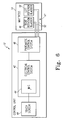
- Fig. 6 is a block schematic diagram of the touch screen control system and pneumatic system of Fig. 1; and
- Fig. 7 is a flowchart illustrating software associated with the touch screen control system of Fig. 6.
- Fig. 1 illustrates a
hospital bed 10 having a therapeutic support surface, for example amattress 14 havingair bladders 48, 50 (Fig. 6), and a touchscreen control system 12 for controlling lateral rotation of themattress 14. Thehospital bed 10 includes abase frame 16, anintermediate frame 20 coupled to thebase frame 16 bylinkages 18, and an articulatingdeck frame 22 that is coupled to theintermediate frame 20 and that supports themattress 14. Thebed 10 also includes ahead end 24, afoot end 26, aleft side rail 28, and aright side rail 30. Thedeck frame 22 includes separate sections that articulate relative to thebase frame 16 and relative to each other, for example, amattress center section 36 that is height adjustable, and amattress head section 32 and amattress foot section 34 that are adjustable in elevation relative to themattress center section 36. Apatient control panel 38 is used to control articulation of thedeck frame 22. - The present disclosure is directed to a system and method for setting and monitoring lateral rotational therapy of
mattress 14. Theair bladders mattress 14 are used to provide positioning and/or therapy, for example, rotational therapy, percussion therapy, vibration therapy, and positioning to assist turning of the patient. Referring to Fig. 6, the touchscreen control system 12 includes atouch screen 40, anelectrical control system 42, and apneumatic control system 46. Theelectrical control system 42 includes acontroller 44 and is electrically coupled to thetouch screen 40 and thepneumatic control system 46. - The
electrical control system 42 provides control and monitoring of thepneumatic control system 46. Thetouch screen 40 provides a graphical user interface for setting and monitoring theelectrical control system 42 and thepneumatic control system 46, which in turn actuate pneumatic aspects of themattress 14. Thepneumatic control system 46 operates abladder system 47 associated with themattress 14. Thebladder system 47 may include, for example aright rotation bladder 48 and aleft rotation bladder 50, or an alternative arrangement of one or more bladders to provide desired patient position and therapy. Thepneumatic control system 46 is coupled to theright rotation bladder 48 and theleft rotation bladder 50 bypneumatic lines 52. Additionally, pressure sensors (not shown) or alternative type sensors such as capacitive, inductive, or optical sensors, may also provide feedback control of thebladders pneumatic control system 46 or theelectrical control system 42. - The
pneumatic control system 46 generally provides pressure or vacuum to, or sealing of thepneumatic lines 52 in order to selectively inflate, deflate, or maintain the inflation of thebladders mattress 14 toward the right, thepneumatic control system 46 deflates theright rotation bladder 48 located under the patient's right side and inflates theleft rotation bladder 50 located under the patient's left side. Alternatively, only one of or a portion of the bladders of thebladder system 47 may be actuated by inflation or deflation to laterally rotate a patient onmattress 14 to different rotational positions. Additionally, thebladder system 47 may comprise bladders that are associated with themattress 14 in an arrangement different from that shown in Fig. 6, as is known in the art. For example, thebladder system 47 may include vertically stacked bladders, one of which is normally inflated and another that is inflated or deflated to provide rotation. Additionally, thepneumatic control system 46 may also provide other pneumatic control, for example, to provide percussion, vibration, or other desired patient therapy or positioning. Thepneumatic control system 46 and thebladder system 47 ofmattress 14 may alternatively include a non-pneumatic mechanical or electrometrical control and motion system, or a pneumatic system utilizing movement elements other than bladders. - Referring to Fig. 2, the
touch screen 40 is shown having an exemplary display arrangement; however, alternative display and control arrangements may be utilized. The exemplary display arrangement of thetouch screen 40 includes amenu display area 60, astatus display area 62, and other graphical user interface elements, for example, astart button 64, astop button 66, and analarm silence button 68. Thetouch screen 40 is of the type that provides visual display elements as well as a touch sensitive surface so that particular display elements may be selected or otherwise manipulated by touching the display surface with a finger or other object and/or dragging the finger or other object across the surface. Theelectrical control system 42 provides signals to touchscreen 40 for displaying the various display elements, and receives signals from thetouch screen 40 relating to touch selected functions. - The
menu display area 60 may includemenu tabs 70 for selecting between various menu display pages, for example, home, rotation, percussion, vibration, maximum inflate, turn assist, and opti-rest. Each menu page such as the home page that is shown in themenu display area 60 may include informational display elements as well as display elements that may be selected or otherwise manipulated by touch in order to set or monitor aspects of the various functions associated with the menu display pages. - The exemplary
status display area 62 shown in Fig. 2 relates to rotational therapy and is used for monitoring and controlling thepneumatic control system 46 and thebladder system 47. Specifically, theexemplary status area 62 relates to lateral rotation, percussion, and vibration ofmattress 14 and thebladder system 47 for pulmonary therapy or decubitus preventional treatment. Theexemplary status area 62 is sub-divided into arotation display area 72,percussion display area 74, andvibration display area 76. Theexemplary display areas - The right rotational position is defined as a lateral rotational position in which the patient is rotated toward the right hand side of the patient. The left rotational position is defined as a lateral rotational position in which the patient is rotated toward the left hand side of the patient. The central rotational position is defined as a lateral rotational position in which the patient is positioned between the right and left rotational positions. The central rotational position may or may not be the position in which the patient is laterally parallel with the
base frame 16 ofhospital bed 10. The rotational position may be set and displayed as, for example, a percentage of the full range of lateral rotation or the lateral rotational angle relative to the patient (or mattress 14) being laterally parallel to thebase frame 16. A rotational dwell time is also associated with each of the rotational positions. The dwell time is the length of time theelectrical control system 42 signals thepneumatic control system 46 to maintain thebladder system 47 in one of the patient rotational positions before signaling thepneumatic control system 46 to actuate thebladder system 47 to provide another of the patient rotational positions. The rotational dwell time may be set and displayed, for example, in units of time such as seconds or minutes: - The exemplary
rotational display area 72 includes apatient display element 78,numerical indication 80, and dwelltime display elements patient display element 78 may be, for example, a graphical representation of a patient viewed axially from thefoot end 26 of thehospital bed 10 because the touchscreen control system 12 may be located at thefoot end 26. Thepatient display element 78 may also include labeling of the patients right side and left side to indicate the direction of rotation of the patient for the various rotational positions. - The
patient display element 78 provides visual indication of the amount of selected rotation and the direction of rotation. This aspect ofcontrol system 12 is helpful visually confirming the actual rotational displacement that will result from a specific numerical setting. For example, various bed systems use degrees, percent of maximum rotation, or a different basis for setting the rotational displacement. Thus, a numerical setting of for example, 45 may anticipate a rotation of 45 degrees, but may actually be setting 45 percent of the maximum rotation, for example, 18 degrees for a bed with a maximum rotation of 40 degrees. Thepatient display element 78 also provides a visual indication of the direction of rotation. For example, the exemplarypatient display element 78 shown in Fig. 2 graphically represents a patient viewed from the approximate vantage point of a person using thecontrol system 12. Thus the rotation of thepatient display element 78 approximately matches the real-world view of the patient direction of rotation and the amount of rotation. - Fig. 3 illustrates using the
rotation display area 72 of the exemplary display arrangement of thetouch screen 40 to set the rotational position of the right rotational position of the patient on themattress 14. In order to select which of the rotational positions, right, central, or left is to be set, one of the position labels 88 located above thenumerical indication 80 is pressed. To set the rotational position, thepatient display element 78 is touched with afinger 79 and the finger is moved across the surface of thetouch screen 40. Theelectrical control system 42 andtouch screen 40 are programmed to rotate thepatient display element 78 accordingly to the touch and movement of touch on thepatient display element 78 portion of thetouch screen 40. - For example, Fig. 3 illustrates touching with the
finger 79 the side of thepatient display element 78 labeled as the right hand patient side and dragging thefinger 79 downward.Electrical control system 42 rotates thepatient display element 78 toward the right hand patient side in response to the dragging of the finger. Simultaneously, theelectrical control system 42 displays the numerical indication 80 (Fig. 4) of the right rotational position setting, which is also proportional to the rotation ofpatient display element 78. - The central rotational positions and left rotational position can similarly be set by touching the
appropriate position label 88 and touching and dragging thepatient display element 78 to provide the desired amount of rotation as indicated by thenumerical indication 80. - Referring to Fig. 4, a
dwell time time display element 82 with afinger 79 to set the desireddwell time 83. The exemplary dwelltime display element time display element 82 and dragging thefinger 79 across the surface of thetouch screen 40 to set theright dwell time 83 to 20 minutes. Thedwell time time display element 84 and the left dwelltime display element 86. Alternative graphical elements and arrangements may also be utilized in place of the exemplary dwelltime display elements - Fig. 5 illustrates a portion of an exemplary alternative
rotational display area 90 that may be substituted for thedisplay area 72. Thealternative display area 90 includes a centralpatient display element 92 for setting and displaying the central rotational position, aright display element 94 for setting and displaying the right rotational position, aleft display element 96 for setting and displaying the left rotational patient position, and selectablegraphical buttons display element 92 may represent the current rotational position of the patient on themattress 14, and theright display element 94 and theleft display element 96 may represent the rotational position settings for right and left patient rotation respectfully. - Fig. 7 is a flow-chart illustrating the
software algorithm 200 associated with thecontroller 44 of theelectrical control system 42 for enabling the above-described aspects of the touchscreen control system 12 illustrated in Figs. 2-4. Thealgorithm 200 begins atstep 202. Instep 204, thecontroller 44 commands display of the graphical elements associated with rotational settings on thetouch screen 40, for example thepatient display element 78, the numericalrotational indicators 80, and the dwelltime display elements step 206, thecontroller 44 determines whether one of thedisplay elements controller 44 determines a display element is being touched, thealgorithm 200 continues atstep 208, else thealgorithm 200 continues atstep 212. - In
step 208, thecontroller 44 adjusts the display element being touched in response to the touching of thetouch screen 40. For example, if thecontroller 44 determines thepatient display element 78 is being touched, theelement 78 is rotated in accordance with touch of and the movement of touch across thetouch screen 40. In addition, thecontroller 44 changes thenumerical indication 80 according to the movement of thepatient display element 78. Similarly, if thecontroller 44 determines one of the dwelltime display elements touch screen 40. - In
step 210, thecontroller 44 stores the rotational parameter associated with the display element being touched. More specifically, the left, central, or right rotational position is set and stored, for example in memory (not shown) associated with theelectrical control system 42, based on the touching of thepatient display element 78 detected by thecontroller 44, and the right, central, and leftrotational dwell time controller 44 determines that the dwelltime display element - In
step 212, thecontroller 44 determines whether rotational therapy is selected, for example by determining that thestart button 64 has been touched on themenu display area 60 of thetouch screen 40. If thecontroller 44 determines that rotational therapy is selected, thealgorithm 200 continues atstep 214, else thealgorithm 200 returns to step 204. Instep 214, thecontroller 44 enables theelectrical control system 42 to control thepneumatic control system 46. For example, thepneumatic control system 46 is commanded to inflate or deflate the rightrotational bladder 48 and the leftrotational bladder 50 of thebladder system 47 in order to provide the rotation, percussion, and vibration of themattress 14 according to the selected made and the stored rotational and other parameters. For example, if rotational therapy is selected, thecontroller 44 signals thepneumatic control system 46 to sequence thebladder system 47 through the right, central, and left rotational positions, maintaining each position for therespective dwell time step 216, thealgorithm 200 is complete. In addition to thealgorithm 200, thecontroller 44 may include other software to enable other aspects of the exemplary display arrangement shown in Fig. 2 and the other functionality of theelectrical control system 42 and thepneumatic control system 46.
Claims (20)
- A patient support apparatus (10), comprising:a patient support surface (14) capable of being rotated to a first position;a control system (12) for controlling the rotation of the support surface (14);a touch screen (40) coupled to the control system (12); anda first display element (78, 92, 94, 96) displayed on the touch screen (40), the display element (78, 92, 94, 96) corresponding to the rotational position of the patient support surface (14) and capable of being rotated by at least one of touching and dragging to an orientation associated with the first position.
- The patient support apparatus (10) of claim 1, wherein the first display element (78, 92, 94, 96) includes a graphical depiction of an axial view of a patient from at least one of a foot end (26) and a head end (24).
- The patient support apparatus (10) of either claim 1 or claim 2, further comprising a second display element (78, 92, 94, 96) capable of being rotated by at least one of touching and dragging to a second position; and
wherein the first display element (78, 92, 94, 96) and the first position are associated with right hand rotation relative to the patient and the second display element (78, 92, 94, 96) and the second position are associated with left hand rotation relative to the patient. - The patient support apparatus (10) of claim 3, further comprising a third display element (78, 92, 94, 96) capable of being rotated by at least one of touching and dragging to a central position, the central position located between the first and second positions.
- The patient support apparatus (10) of claim 4, further comprising at least a fourth display element (82, 84, 86) including at least one of a graphical and a numerical indicator (82, 84, 86) of a dwell time (83, 85, 87) associated with at least one of right, left, and central positions.
- The patient support apparatus (10) of claim 5, wherein the at least a fourth display element includes an indicating element (82, 84, 86) for setting the dwell time (83, 85, 87) by at least one of touching and dragging the indicating element to the dwell time.
- The patient support apparatus (10) of any preceding claim, wherein the control system (12) includes a pneumatic control (46) and the patient support surface (14) includes at least one bladder (48, 50) pneumatically coupled to the pneumatic control (46).
- A system (12) for controlling a patient support surface (14), comprising:a touch screen (40);a controller (42) coupled to the touch screen (40); andsoftware enabling the controller (42) to:display a first display element (78, 82, 84, 86, 92, 94, 96) on the touch screen (40);monitor touch of the first display element (78, 82, 84, 86, 92, 94, 96);rotate the first display element (78, 82, 84, 86, 92, 94, 96) in response to touch; andcommand rotation of the support surface (14) based on the rotation of the first display element (78, 82, 84, 86, 92, 94, 96).
- The system 12 of claim 8, wherein the first display element (78, 82, 84, 86, 92, 94, 96) includes a graphical depiction of an axial view of a person from at least one of a foot end (26) and a head end (24).
- The system (12) of either claim 8 or claim 9, wherein the software further enables the controller (42) to:display a second display element (78, 82, 84, 86, 92, 94, 96);monitor touch of the second display element (78, 82, 84, 86, 92, 94, 96);rotate the second display element (78, 82, 84, 86, 92, 94, 96) in response to touch; andcommand rotation of the support surface (14) based on the rotation of the second display element (78, 82, 84, 86, 92, 94, 96);wherein the first display element (78, 82, 84, 86, 92, 94, 96) is associated with rotation of the support surface (14) in a first direction and the second display element (78, 82, 84, 86, 92, 94, 96) is associated with rotation of the support surface (14) in a second direction.
- The system (12) of claim 10, wherein the software further enables the controller (42) to:display a third display element (78, 82, 84, 86, 92, 94, 96);monitor touch of the third display element (78, 82, 84, 86, 92, 94, 96);rotate the display of the third display element (78, 82, 84, 86, 92, 94, 96) in response to touch; andcommand rotation of the support surface (14) based on the rotation of the third display element (78, 82, 84, 86, 92, 94, 96).
- The system (12) of claim 11, wherein the software further enables the controller (42) to display at least a fourth display element (78, 80, 82, 83, 84, 85 86, 87, 92, 94, 96) including at least one of a graphical indicator (78, 82, 84, 86, 92, 94, 96) and a numerical indicator (80, 83, 85, 87) of a parameter associated with at least one of right, left, and central rotational positions of the support surface (14).
- The system (12) of claim 12, wherein the parameter includes dwell time (83, 85, 87).
- The system (12) of either claim 12 or clam 13, wherein the software further enables the controller (42) to:display and monitor touch of the at least one of a graphical indicator (78, 82, 84, 86, 92, 94, 96) and a numerical indicator (80, 83, 85, 87); andset the parameter based on touch of the at least one of a graphical indicator (78, 82, 84, 86, 92, 94, 96) and a numerical indicator (80, 83, 85, 87).
- The system (12) of any one of claims 8 to 14, wherein the support surface (14) includes a hospital bed mattress (14).
- A method of controlling rotational parameters of a patient support surface (14) comprising:displaying graphical elements (78, 82, 84, 86, 92, 94, 96) on a touch sensitive display screen (40);monitoring touch of the graphical elements (78, 82, 84, 86, 92, 94, 96);moving the graphical elements (78, 82, 84, 86, 92, 94, 96) in response to touch; andsetting a rotational parameter based on the movement of the graphical element (78, 82, 84, 86, 92, 94, 96).
- The method of claim 16, wherein the graphical elements (78, 82, 84, 86, 92, 94, 96) include an element illustrative of patient rotational position (78, 92, 94, 96).
- The method of either claim 16 or claim 17, wherein the rotational parameters includes at least one of a left rotational position, right rotational position, central rotational position, left dwell time (87), right dwell time (83), and central dwell time (85).
- The method of any one of claims 16 to 18, wherein the graphical element (78, 82, 84, 86, 92, 94, 96) illustrates at least one of rotational position and rotational position dwell time (83, 85, 87).
- The method of any one of claims 16 to 19, further comprising controlling a pneumatic control system (46) based on the rotational parameter, the pneumatic control system (46) capable of inflating and deflating at least one pneumatic bladder (48,50) associated with the patient support surface (14).
Applications Claiming Priority (1)
| Application Number | Priority Date | Filing Date | Title |
|---|---|---|---|
| US63386304P | 2004-12-07 | 2004-12-07 |
Publications (2)
| Publication Number | Publication Date |
|---|---|
| EP1669049A1 true EP1669049A1 (en) | 2006-06-14 |
| EP1669049B1 EP1669049B1 (en) | 2008-08-27 |
Family
ID=35871153
Family Applications (1)
| Application Number | Title | Priority Date | Filing Date |
|---|---|---|---|
| EP05257540A Active EP1669049B1 (en) | 2004-12-07 | 2005-12-07 | Touch screen control for lateral rotation of a hospital bed mattress |
Country Status (4)
| Country | Link |
|---|---|
| US (1) | US20060117482A1 (en) |
| EP (1) | EP1669049B1 (en) |
| CA (1) | CA2529185A1 (en) |
| DE (1) | DE602005009309D1 (en) |
Cited By (3)
| Publication number | Priority date | Publication date | Assignee | Title |
|---|---|---|---|---|
| WO2008139191A1 (en) * | 2007-05-15 | 2008-11-20 | Genie Care | Turning platform |
| WO2009132843A1 (en) * | 2008-04-29 | 2009-11-05 | Martin Teschner | Controllable hospital bed |
| WO2016196864A1 (en) * | 2015-06-05 | 2016-12-08 | Stryker Corporation | Patient support apparatuses with dynamic control panels |
Families Citing this family (42)
| Publication number | Priority date | Publication date | Assignee | Title |
|---|---|---|---|---|
| US7319386B2 (en) | 2004-08-02 | 2008-01-15 | Hill-Rom Services, Inc. | Configurable system for alerting caregivers |
| US7805784B2 (en) | 2005-12-19 | 2010-10-05 | Stryker Corporation | Hospital bed |
| US9038217B2 (en) | 2005-12-19 | 2015-05-26 | Stryker Corporation | Patient support with improved control |
| US7931334B1 (en) | 2004-12-07 | 2011-04-26 | Steven Jerome Caruso | Custom controlled seating surface technologies |
| US11617451B1 (en) | 2004-12-07 | 2023-04-04 | Steven Jerome Caruso | Custom controlled seating surface technologies |
| US8596716B1 (en) | 2008-12-31 | 2013-12-03 | Steven Jerome Caruso | Custom controlled seating surface technologies |
| JP5231222B2 (en) * | 2005-07-08 | 2013-07-10 | ヒル−ロム サービシーズ,インコーポレイティド | Patient support control unit |
| US7779493B2 (en) * | 2005-10-27 | 2010-08-24 | Stryker Corporation | Ergonomic control apparatus for a patient support apparatus |
| WO2007075699A2 (en) | 2005-12-19 | 2007-07-05 | Stryker Corporation | Hospital bed |
| US11246776B2 (en) | 2005-12-19 | 2022-02-15 | Stryker Corporation | Patient support with improved control |
| WO2007092886A2 (en) | 2006-02-08 | 2007-08-16 | Hill-Rom Services, Inc. | User module for a patient support |
| US7465280B2 (en) | 2006-09-14 | 2008-12-16 | Rawls-Meehan Martin B | Methods and systems of mounting a vibration motor to an adjustable bed |
| US10064784B2 (en) | 2006-09-14 | 2018-09-04 | Martin B. Rawls-Meehan | System and method of an adjustable bed with a vibration motor |
| US8926535B2 (en) | 2006-09-14 | 2015-01-06 | Martin B. Rawls-Meehan | Adjustable bed position control |
| US10864137B2 (en) | 2006-09-14 | 2020-12-15 | Ascion, Llc | System and method of an adjustable bed with a vibration motor |
| US8069512B2 (en) | 2006-09-14 | 2011-12-06 | Martin B Rawls-Meehan | Adjustable bed frame |
| US20080234555A1 (en) * | 2007-03-23 | 2008-09-25 | Stryker Corporation | Patient care system |
| US8572778B2 (en) | 2007-03-30 | 2013-11-05 | Hill-Rom Services, Inc. | User interface for hospital bed |
| AU2008316981A1 (en) * | 2007-10-22 | 2009-04-30 | Martin B. Rawls-Meehan | Adjustable bed position control |
| US8593284B2 (en) | 2008-09-19 | 2013-11-26 | Hill-Rom Services, Inc. | System and method for reporting status of a bed |
| KR200447696Y1 (en) * | 2009-07-03 | 2010-02-12 | 김경조 | Rotation bed |
| US8752220B2 (en) * | 2009-07-10 | 2014-06-17 | Hill-Rom Services, Inc. | Systems for patient support, monitoring and treatment |
| WO2012061406A2 (en) | 2010-11-01 | 2012-05-10 | Rawls-Meehan Martin B | Adjustable bed controls |
| WO2013071246A1 (en) | 2011-11-11 | 2013-05-16 | Hill-Rom Services, Inc. | Person support apparatus |
| WO2013123119A1 (en) | 2012-02-15 | 2013-08-22 | Stryker Corporation | Patient support apparatus and controls therefor |
| US9655798B2 (en) | 2013-03-14 | 2017-05-23 | Hill-Rom Services, Inc. | Multi-alert lights for hospital bed |
| US9782005B2 (en) | 2014-07-25 | 2017-10-10 | Stryker Corporation | Medical support apparatus |
| DE112014002808T5 (en) * | 2013-06-14 | 2016-04-14 | Segars California Partners, Lp | Infant warmer with integrated touch screen and display insulation attachment |
| AU2015292418B2 (en) * | 2014-07-25 | 2019-10-24 | Arjo Ip Holding Ab | A system and method to physically and electronically configure an air mattress system for multiple users |
| BR102017001670B1 (en) * | 2017-01-26 | 2021-01-12 | Kléber Elias Tavares | oscillating bed for the prevention of decubitus ulcers |
| US11103398B2 (en) | 2017-05-17 | 2021-08-31 | Hill-Rom Services, Inc. | Flexible overhead arm |
| US11096850B2 (en) * | 2017-06-27 | 2021-08-24 | Stryker Corporation | Patient support apparatus control systems |
| US10463526B1 (en) | 2018-05-07 | 2019-11-05 | Levy Zur | Programmable pressure management support surface |
| US11367535B2 (en) | 2018-09-30 | 2022-06-21 | Hill-Rom Services, Inc. | Patient care system for a home environment |
| US11357682B2 (en) | 2018-09-30 | 2022-06-14 | Hill-Rom Services, Inc. | Structures for causing movement of elements of a bed |
| US11229568B2 (en) | 2018-09-30 | 2022-01-25 | Hill-Rom Services, Inc. | Mattress support for adding hospital bed functionality to an in-home bed |
| US11241347B2 (en) | 2018-10-01 | 2022-02-08 | Hill-Rom Services, Inc. | Mattress support for adding hospital bed modular control system for upgrading a bed to include movable components |
| US11400001B2 (en) | 2018-10-01 | 2022-08-02 | Hill-Rom Services, Inc. | Method and apparatus for upgrading a bed to include moveable components |
| CN109820663A (en) * | 2019-01-31 | 2019-05-31 | 嘉兴跃泓护理设备有限公司 | Nursing bed method for remotely controlling and its system |
| US10959534B2 (en) | 2019-02-28 | 2021-03-30 | Hill-Rom Services, Inc. | Oblique hinged panels and bladder apparatus for sleep disorders |
| US20210378894A1 (en) * | 2020-06-09 | 2021-12-09 | Hill-Rom Services, Inc. | Preview function for continuous lateral rotation therapy |
| WO2023177578A1 (en) * | 2022-03-14 | 2023-09-21 | Stryker Corporation | Patient support apparatus with mattress and mattress cable |
Citations (3)
| Publication number | Priority date | Publication date | Assignee | Title |
|---|---|---|---|---|
| JPH09103978A (en) * | 1995-10-04 | 1997-04-22 | Yaskawa Electric Corp | Robot control device |
| US5745937A (en) * | 1995-08-04 | 1998-05-05 | Hill-Rom, Inc. | Support surfaces for a bed |
| EP1452159A2 (en) * | 2001-03-29 | 2004-09-01 | KCI Licensing, Inc. | Prone positioning therapeutic bed |
Family Cites Families (56)
| Publication number | Priority date | Publication date | Assignee | Title |
|---|---|---|---|---|
| US4274167A (en) * | 1979-08-31 | 1981-06-23 | Immel Joseph D | Oscillating bed |
| US4763643A (en) * | 1981-01-19 | 1988-08-16 | Kinetic Concepts, Inc. | Arc changing apparatus for a therapeutic oscillating bed |
| US5152024A (en) * | 1985-04-17 | 1992-10-06 | Thomas J. Ring | Therapeutic table-with time based tilt motor controller |
| IE58731B1 (en) * | 1986-05-02 | 1993-11-03 | Alliance Investments Ltd | A therapeutic bed |
| US6115860A (en) * | 1986-09-09 | 2000-09-12 | Kinetic Concepts, Inc. | Feedback controlled patient support |
| US5003654A (en) * | 1986-09-09 | 1991-04-02 | Kinetic Concepts, Inc. | Method and apparatus for alternating pressure of a low air loss patient support system |
| US4949414A (en) * | 1989-03-09 | 1990-08-21 | Ssi Medical Services, Inc. | Modular low air loss patient support system and methods for automatic patient turning and pressure point relief |
| US5052067A (en) * | 1989-03-09 | 1991-10-01 | Ssi Medical Services, Inc. | Bimodal system for pressurizing a low air loss patient support |
| US5606754A (en) * | 1989-03-09 | 1997-03-04 | Ssi Medical Services, Inc. | Vibratory patient support system |
| US5251349A (en) * | 1989-03-09 | 1993-10-12 | Ssi Medical Services, Inc. | Multi-modal patient support system |
| US5062167A (en) * | 1989-03-09 | 1991-11-05 | Ssi Medical Services, Inc. | Bimodal turning method |
| US5121513A (en) * | 1989-03-09 | 1992-06-16 | Ssi Medical Services, Inc. | Air sack support manifold |
| US5182826A (en) * | 1989-03-09 | 1993-02-02 | Ssi Medical Services, Inc. | Method of blower control |
| US5095568A (en) * | 1989-05-22 | 1992-03-17 | Ssi Medical Services, Inc. | Modular low air loss patient support system |
| US5077843A (en) * | 1990-07-28 | 1992-01-07 | Hill-Rom Company, Inc. | Hospital bed and assemblies of hospital care apparatus |
| US5325551A (en) * | 1992-06-16 | 1994-07-05 | Stryker Corporation | Mattress for retarding development of decubitus ulcers |
| US5715548A (en) * | 1994-01-25 | 1998-02-10 | Hill-Rom, Inc. | Chair bed |
| US5611096A (en) * | 1994-05-09 | 1997-03-18 | Kinetic Concepts, Inc. | Positional feedback system for medical mattress systems |
| US6892405B1 (en) * | 1994-05-09 | 2005-05-17 | Kci Licensing, Inc. | Therapeutic bed and related apparatus and methods |
| US5664270A (en) * | 1994-07-19 | 1997-09-09 | Kinetic Concepts, Inc. | Patient interface system |
| US5559301A (en) * | 1994-09-15 | 1996-09-24 | Korg, Inc. | Touchscreen interface having pop-up variable adjustment displays for controllers and audio processing systems |
| US5542138A (en) * | 1995-02-06 | 1996-08-06 | Williams; Terry N. | Bedside control unit for a hospital bed |
| US5926002A (en) * | 1995-02-21 | 1999-07-20 | Getinge/Castle, Inc. | Pendent with safety features for patient handling apparatus |
| US6119291A (en) * | 1995-08-04 | 2000-09-19 | Hill-Rom, Inc. | Percussion and vibration therapy apparatus |
| US7017208B2 (en) * | 1995-08-04 | 2006-03-28 | Hill-Rom Services, Inc. | Hospital bed |
| US6584628B1 (en) * | 1995-08-04 | 2003-07-01 | Hill-Rom Services, Inc. | Hospital bed having a rotational therapy device |
| US6047424A (en) * | 1995-08-04 | 2000-04-11 | Hill-Rom, Inc. | Bed having modular therapy devices |
| US5745942A (en) * | 1995-10-19 | 1998-05-05 | Geomarine Systems, Inc. | Simplified control for lateral rotation therapy mattresses |
| US6874181B1 (en) * | 1995-12-18 | 2005-04-05 | Kci Licensing, Inc. | Therapeutic bed |
| US5626151A (en) * | 1996-03-07 | 1997-05-06 | The United States Of America As Represented By The Secretary Of The Army | Transportable life support system |
| US5647079A (en) * | 1996-03-20 | 1997-07-15 | Hill-Rom, Inc. | Inflatable patient support surface system |
| US5966763A (en) * | 1996-08-02 | 1999-10-19 | Hill-Rom, Inc. | Surface pad system for a surgical table |
| US6536056B1 (en) * | 1996-11-18 | 2003-03-25 | John H. Vrzalik | Bariatric treatment system and related methods |
| US7346945B2 (en) * | 1996-11-18 | 2008-03-25 | Kci Licensing, Inc. | Bariatric treatment system and related methods |
| CA2299356A1 (en) * | 1997-08-08 | 1999-02-18 | Hill-Rom, Inc. | Proning bed |
| US6021533A (en) * | 1997-08-25 | 2000-02-08 | Hill-Rom, Inc. | Mattress apparatus having a siderail down sensor |
| EP1009262B1 (en) * | 1997-08-25 | 2003-12-17 | Hill-Rom, Inc. | Air supply apparatus for an air mattress |
| US7010369B2 (en) * | 1997-11-07 | 2006-03-07 | Hill-Rom Services, Inc. | Medical equipment controller |
| ATE245397T1 (en) * | 1997-11-07 | 2003-08-15 | Hill Rom Co Inc | THERMAL CONTROL SYSTEM FOR PATIENTS |
| US6008598A (en) * | 1998-04-22 | 1999-12-28 | Patmark Company, Inc. | Hand-held controller for bed and mattress assembly |
| WO1999052487A1 (en) * | 1998-04-14 | 1999-10-21 | Hill-Rom, Inc. | Communication and bed function control apparatus |
| EP1194105A1 (en) * | 1999-04-21 | 2002-04-10 | Hill-Rom Services, Inc. | Proning bed |
| DE19922258C2 (en) * | 1999-05-14 | 2003-06-26 | Siemens Ag | Medical device |
| JP4601887B2 (en) * | 1999-12-29 | 2010-12-22 | ヒル−ロム サービシーズ,インコーポレイティド | Hospital bed |
| WO2001086605A2 (en) * | 2000-05-05 | 2001-11-15 | Hill-Rom Services, Inc. | Hospital monitoring and control system and method |
| US6409654B1 (en) * | 2000-08-15 | 2002-06-25 | Mcclain Anthony | Incubator system with monitoring and communicating capabilities |
| US6529144B1 (en) * | 2000-09-22 | 2003-03-04 | Motorola Inc. | Method and apparatus for motion activated control of an electronic device |
| US6978499B2 (en) * | 2001-05-25 | 2005-12-27 | Hill-Rom Services, Inc. | Architectural bed docking apparatus |
| EP1421458B1 (en) * | 2001-08-03 | 2010-04-07 | Hill-Rom Services, Inc. | Patient point-of-care computer system |
| CA2461167A1 (en) * | 2001-10-02 | 2003-04-10 | Hill-Rom Services, Inc. | Integrated barrier and fluid supply for a hospital bed |
| DE10353846A1 (en) * | 2003-11-18 | 2005-06-16 | Maquet Gmbh & Co. Kg | Method of preparation of equipment intended for the performance of medical or surgical procedures |
| DE102004003717B4 (en) * | 2004-01-26 | 2006-04-06 | Siemens Ag | hospital bed |
| EP1621172A3 (en) * | 2004-07-26 | 2006-05-31 | Hill-Rom Services, Inc. | Modular bed system |
| EP1621170B1 (en) * | 2004-07-30 | 2012-10-03 | Hill-Rom Services, Inc. | Patient support having an adjustable popliteal length apparatus, system and method |
| US7464425B2 (en) * | 2004-08-04 | 2008-12-16 | Hill-Rom Services, Inc. | Hospital bed |
| US7260860B2 (en) * | 2004-08-04 | 2007-08-28 | Hill-Rom Services, Inc. | Mattress system for a hospital bed |
-
2005
- 2005-12-02 US US11/292,675 patent/US20060117482A1/en not_active Abandoned
- 2005-12-06 CA CA002529185A patent/CA2529185A1/en not_active Abandoned
- 2005-12-07 EP EP05257540A patent/EP1669049B1/en active Active
- 2005-12-07 DE DE602005009309T patent/DE602005009309D1/en active Active
Patent Citations (3)
| Publication number | Priority date | Publication date | Assignee | Title |
|---|---|---|---|---|
| US5745937A (en) * | 1995-08-04 | 1998-05-05 | Hill-Rom, Inc. | Support surfaces for a bed |
| JPH09103978A (en) * | 1995-10-04 | 1997-04-22 | Yaskawa Electric Corp | Robot control device |
| EP1452159A2 (en) * | 2001-03-29 | 2004-09-01 | KCI Licensing, Inc. | Prone positioning therapeutic bed |
Non-Patent Citations (1)
| Title |
|---|
| PATENT ABSTRACTS OF JAPAN vol. 1997, no. 08 29 August 1997 (1997-08-29) * |
Cited By (7)
| Publication number | Priority date | Publication date | Assignee | Title |
|---|---|---|---|---|
| WO2008139191A1 (en) * | 2007-05-15 | 2008-11-20 | Genie Care | Turning platform |
| US8776290B2 (en) | 2007-05-15 | 2014-07-15 | Genie Care | Turning platform |
| WO2009132843A1 (en) * | 2008-04-29 | 2009-11-05 | Martin Teschner | Controllable hospital bed |
| WO2016196864A1 (en) * | 2015-06-05 | 2016-12-08 | Stryker Corporation | Patient support apparatuses with dynamic control panels |
| GB2552917A (en) * | 2015-06-05 | 2018-02-14 | Stryker Corp | Patient support apparatuses with dynamic control panels |
| US10420688B2 (en) | 2015-06-05 | 2019-09-24 | Stryker Corporation | Patient support apparatuses with dynamic control panels |
| GB2552917B (en) * | 2015-06-05 | 2021-04-07 | Stryker Corp | Patient support apparatuses with dynamic control panels |
Also Published As
| Publication number | Publication date |
|---|---|
| EP1669049B1 (en) | 2008-08-27 |
| CA2529185A1 (en) | 2006-06-07 |
| US20060117482A1 (en) | 2006-06-08 |
| DE602005009309D1 (en) | 2008-10-09 |
Similar Documents
| Publication | Publication Date | Title |
|---|---|---|
| EP1669049B1 (en) | Touch screen control for lateral rotation of a hospital bed mattress | |
| US11116681B2 (en) | Patient support systems and methods of use | |
| JP4994791B2 (en) | Operating table bed adjustment device | |
| US11633313B2 (en) | Patient support apparatus with touchscreen | |
| US20210346220A1 (en) | Patient Support Apparatus Control Systems | |
| US6560492B2 (en) | Medical equipment controller | |
| EP3090718B1 (en) | Multi-mode sacral unloading pressure relief in a patient support surface | |
| EP3351229A1 (en) | Patient support apparatus having urinary drainage bag lockout feature | |
| US20220071823A1 (en) | Patient Support Apparatus User Interfaces | |
| US20230027244A1 (en) | Patient Support Apparatus User Interfaces | |
| US20210369522A1 (en) | Patient apparatus with touchscreen | |
| EP3922229A1 (en) | Preview function for continuous lateral rotation therapy | |
| US11800994B2 (en) | Patient support apparatus with improved user interface | |
| US20230122043A1 (en) | Person support surfaces including set by preview function for continuous lateral rotation therapy | |
| KR20190089399A (en) | A operating table device for intuitive control of operating table | |
| EP3766469A1 (en) | Patient support apparatus including patient risk determination system | |
| EP4252731A1 (en) | Surgical table control device | |
| JP2874035B1 (en) | Operation control system and operation control method for electric bed | |
| JPH11253495A (en) | Motor-driven bed having function of displaying position of bottom |
Legal Events
| Date | Code | Title | Description |
|---|---|---|---|
| PUAI | Public reference made under article 153(3) epc to a published international application that has entered the european phase |
Free format text: ORIGINAL CODE: 0009012 |
|
| AK | Designated contracting states |
Kind code of ref document: A1 Designated state(s): AT BE BG CH CY CZ DE DK EE ES FI FR GB GR HU IE IS IT LI LT LU LV MC NL PL PT RO SE SI SK TR |
|
| AX | Request for extension of the european patent |
Extension state: AL BA HR MK YU |
|
| 17P | Request for examination filed |
Effective date: 20061205 |
|
| 17Q | First examination report despatched |
Effective date: 20070115 |
|
| AKX | Designation fees paid |
Designated state(s): DE FR GB |
|
| GRAP | Despatch of communication of intention to grant a patent |
Free format text: ORIGINAL CODE: EPIDOSNIGR1 |
|
| GRAS | Grant fee paid |
Free format text: ORIGINAL CODE: EPIDOSNIGR3 |
|
| GRAA | (expected) grant |
Free format text: ORIGINAL CODE: 0009210 |
|
| AK | Designated contracting states |
Kind code of ref document: B1 Designated state(s): DE FR GB |
|
| REG | Reference to a national code |
Ref country code: GB Ref legal event code: FG4D |
|
| REF | Corresponds to: |
Ref document number: 602005009309 Country of ref document: DE Date of ref document: 20081009 Kind code of ref document: P |
|
| PLBE | No opposition filed within time limit |
Free format text: ORIGINAL CODE: 0009261 |
|
| STAA | Information on the status of an ep patent application or granted ep patent |
Free format text: STATUS: NO OPPOSITION FILED WITHIN TIME LIMIT |
|
| 26N | No opposition filed |
Effective date: 20090528 |
|
| REG | Reference to a national code |
Ref country code: FR Ref legal event code: PLFP Year of fee payment: 11 |
|
| REG | Reference to a national code |
Ref country code: FR Ref legal event code: PLFP Year of fee payment: 12 |
|
| REG | Reference to a national code |
Ref country code: FR Ref legal event code: PLFP Year of fee payment: 13 |
|
| REG | Reference to a national code |
Ref country code: DE Ref legal event code: R082 Ref document number: 602005009309 Country of ref document: DE Representative=s name: PRUEFER & PARTNER MBB PATENTANWAELTE RECHTSANW, DE |
|
| PGFP | Annual fee paid to national office [announced via postgrant information from national office to epo] |
Ref country code: DE Payment date: 20221122 Year of fee payment: 18 |
|
| PGFP | Annual fee paid to national office [announced via postgrant information from national office to epo] |
Ref country code: GB Payment date: 20231121 Year of fee payment: 19 |
|
| PGFP | Annual fee paid to national office [announced via postgrant information from national office to epo] |
Ref country code: FR Payment date: 20231122 Year of fee payment: 19 |