EP1661703A2 - Method of cleaning and keeping clean an inking unit of a printing device and the corresponding ink unit - Google Patents
Method of cleaning and keeping clean an inking unit of a printing device and the corresponding ink unit Download PDFInfo
- Publication number
- EP1661703A2 EP1661703A2 EP05077324A EP05077324A EP1661703A2 EP 1661703 A2 EP1661703 A2 EP 1661703A2 EP 05077324 A EP05077324 A EP 05077324A EP 05077324 A EP05077324 A EP 05077324A EP 1661703 A2 EP1661703 A2 EP 1661703A2
- Authority
- EP
- European Patent Office
- Prior art keywords
- inking
- roller
- rollers
- inking unit
- ink
- Prior art date
- Legal status (The legal status is an assumption and is not a legal conclusion. Google has not performed a legal analysis and makes no representation as to the accuracy of the status listed.)
- Withdrawn
Links
Images
Classifications
-
- B—PERFORMING OPERATIONS; TRANSPORTING
- B41—PRINTING; LINING MACHINES; TYPEWRITERS; STAMPS
- B41F—PRINTING MACHINES OR PRESSES
- B41F35/00—Cleaning arrangements or devices
- B41F35/04—Cleaning arrangements or devices for inking rollers
-
- B—PERFORMING OPERATIONS; TRANSPORTING
- B41—PRINTING; LINING MACHINES; TYPEWRITERS; STAMPS
- B41P—INDEXING SCHEME RELATING TO PRINTING, LINING MACHINES, TYPEWRITERS, AND TO STAMPS
- B41P2235/00—Cleaning
- B41P2235/10—Cleaning characterised by the methods or devices
- B41P2235/26—Spraying devices
Abstract
Description
- The present invention relates to a method of cleaning and keeping clean an inking unit of a printing device, and to an inking unit arranged for being able to carry out the method. The inking unit comprises a train of rollers with a number of successive inking rollers by which ink from an ink duct is brought onto the printing cloth, printing block. After a certain production time or in case the inking unit should be changed to another colour, the train of inking rollers and the housing in which it is accommodated, must be cleaned. This is a cumbersome and time-consuming operation, in which considerable amounts of diluents and/or cleaners are used, since the amount of ink should not only be removed from the entire train of inking rollers, but from the inside of the housing as well. The latter is definitely required for preventing a preceding colour from blending with a new colour in the end.
- Firstly, the object of the invention is to facilitate the cleaning operation and further to prevent deposition of ink on the inside of the housing and other parts.
- Accordingly, the invention provides for that the cleaner is applied on at least a part of the rolling length of one inking roller of the ink unit with the help of at least one spraying member, with at least one of the inking rollers being driven and at least part of the cleaning is carried out across corresponding parts of the rolling lengths of successive inking rollers of the inking unit. Additionally, it is provided for that with at least one inking roller, ink and cleaner is scraped across at least a part of the rolling length of the inking roller.
- By successive cleaning of parts of the rolling lengths of the inking rollers the method according to the invention provides the great advantage that the successive inking rollers can maintain their mutual grip through the parts not covered by cleaner, due to which the successive inking rollers can be continued to be driven. In this way, the cleaner can be distributed across the successive inking rollers and these can be cleaned across a part of their lengths, in which the ink and cleaner can be removed by the scraping member. Then, among the parts of the successive inking rollers thus cleaned, sufficient grip will be reestablished to be able to drive the inking rollers during cleaning of the further parts of the successive inking rollers.
- Although it is basically possible to provide spraying members for each inking roller, in practice, this will cause problems with the available space within an inking unit and furthermore, in most situations this will not be required. Practice has shown that the cleaner is passed quickly enough, and in sufficient amounts, to the successive inking rollers and distributed across them. According to a further development, it is thus provided for, that for at least two inking rollers, two spraying members per inking roller have been mounted, in which each of the spraying members is arranged to apply cleaner across at least half the rolling length of the inking roller concerned. Practice has shown that in this way a more than sufficient cleaning of the inking rollers is achieved. Dividing the rolling lengths in more than two parts is also possible, however, this is not necessary for having the inking rollers properly engage one another during cleaning. With greater lengths of the inking rollers it might be desirable to increase the number of spraying members per roller length.
- According to yet a further development it is provided for that a first set of spraying members applies cleaner onto corresponding parts of
the rolling lengths of two successive inking rollers and a second set of spraying members applies cleaner on corresponding parts of the rolling lengths of two further successive inking rollers in the inking unit. Thus, it is achieved that the cleaner is passed much better to all successive inking rollers and thus is distributed more quickly across the entire inking unit. - To that end, it can further be provided for, that the second set of spraying members, with an inking roller transferring the ink onto a higher and a lower further inking roller, are directed at the transferring inking roller and the higher further inking roller. Although the cleaner will also be passed to higher inking rollers if it is applied onto lower inking rollers, especially in case of a division in the train of rollers into higher and lower parts, it is particularly advantageous to apply the cleaner onto both the inking roller where the division begins and onto the connecting higher inking roller.
- Additionally, apart from the possible division in one or more further inking roller sequences, other configurations with spraying members are possible, in which however the starting point remains that no more than a part of the rolling lengths of successive inking rollers will be provided with ink, as a result of which one can keep on using the normal driving mechanism of the inking rollers for distributing the cleaner and finally cleaning the entire rolling lengths of the inking rollers.
- Practical tests have shown that with the method according to the invention a proper cleaning can be achieved using considerably less cleaner, which is a significant advantage.
- Normal use of an inking unit gives rise to a haze of fine ink droplets spreading through the entire interior of the inking unit. This so-called ink mist arises for the most part at the plane of contact between successive, rapidly rotating inking rollers. Further, this ink mist arises at the vibrating roller which, for dosage of the ink, is reciprocated between the inking roller, being in direct contact with the ink in the ink duct, and a further inking roller in the train of rollers. During cleaning of the inking rollers, in which the ink is diluted with the cleaner, a comparable haze occurs. This haze is limited by adjusting the driving speed of the inking rollers during cleaning thereof, which is clearly lower than the speed during normal use.
- A further object of the invention is to prevent contamination of the inking unit by said inking mist, both during use of the inking unit and during cleaning thereof, to which end it is provided for, that said ink mist arising during use or cleaning of the inking unit is extracted. It is important that one employs a moderate air flow such that no turbulences will occur in the ink mist and it can be discharged uniformly without still being deposited against the housing and other parts of the inking unit.
- According to a further development, an air flow for exhausting the ink mist is generated which is led to a filtering member at or near the inking unit from a lateral direction or lateral directions. By having the air flow start at the sides of the inking rollers, the ink mist can be kept away from the sides of the housing and can be directed, towards the outer end of the housing, and to the filtering member mounted there, along the engaging parts of the inking rollers.
- In order to be able to generate such a uniform air flow, it is further provided for, that the inking rollers of the inking unit are accommodated in a housing extending from near the printing roller with printing cloth up to near or across the ink duct, said housing being closed entirely or for the larger part between said outer ends, in which an underpressure member for generating an air flow within the housing is provided at one outer end. By employing an underpressure member, it is possible to monitor the flow of the ink mist towards the filtering member to a large degree and to prevent deposition onto other parts than the effective surfaces of the inking rollers.
- Additionally, it is preferably further provided for, that the housing has openings laterally of the effective axial surface of one or more of the successive inking rollers, and that the underpressure member is mounted near the ink duct.
- The method of cleaning the inking unit is preferably carried out entirely of partly automated.
- The invention is further explained by means of the example illustrated in the drawing, in which:
- Fig. 1 shows a schematic cross-section of an inking unit;
- Fig. 2 shows a schematic cross-section of an inking unit during cleaning thereof;
- Fig. 3 shows a schematic plan view of a part of the inking unit with the spraying members and some of the inking rollers;
- Fig. 4 shows a schematic plan view of the inking unit housing; and
- Fig. 5 shows a schematic rear view of the inking unit with the underpressure member.
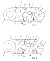
- Fig. 1 illustrates a cross-section of an
inking unit 1, comprising ahousing 2 in which atrain 3 of rollers is mounted by which the ink from ink duct 4 is passed to theprinting roller 5 having a printing cloth or printing block not further indicated. With afirst inking roller 6, the ink is taken from the ink duct and transferred onto a further inkingroller 8 by a vibratingroller 7. The vibratingroller 7 is reciprocated between theinking rollers roller 8, the ink is transferred onto distributingroller 9, from which the ink is brought onto the printing cloth or printing block through an upper set ofinking rollers inking rollers inking rollers rollers - Instead of this succession of inking rollers, many other successions are possible, which, however, does not bring any essential change to the invention.
- A scraping member having a
scraping knife 14 and areceptacle 15 is mounted against the lower driveninking roller 12. The scraping knife can be mounted against the roller and be moved away from the roller by means not further indicated in the drawing. - An
underpressure member 16 having anorifice 17 andfilter 18 is mounted at the bottom of thehousing 2 of the inkingunit 1 near the ink duct 4 and accompanyingroller 6. The underpressure formed withunderpressure member 16 causes the ink mist arising during use of the inking unit to be led to the underpressure member in a very uniform air flow, where the ink is captured by thefilter 18, and the air let off below the ink duct 4. - Fig. 2 shows the situation during cleaning of the inking unit, in which spraying
members roller roller unit 1. - Ink duct 4 and accompanying inking
roller 6 are cleaned individually. To that end, the ink duct 4 can be taken from the inkingunit 1.Roller 6 is an inking roller having a driving mechanism of its own and running free fromrollers 7 through 13 during cleaning of saidrollers 7 through 13 and thus is cleaned separately from them. Further,printing roller 5 is kept free from inkingrollers - The cleaner emerging from spraying
member 19 dilutes the ink onrollers ink roller 12 through distributingroller 9, and it can be removed from said driveninking roller 12 by ascraping knife 14. Before removing the diluted ink, it is first led across inkingroller 13 in order to dilute the ink there as well and to subsequently remove it through the drivenroller 12. - The
scraping knife 14 can be divided in segments and be mounted only against the part of the inkingroller 12 upon which the cleaner is applied. However, this would render the scraping member unnecessarily complicated and it is furthermore in no way required since the ink should be removed from the entire length of the roller in the end. Inkingroller 12 is preferably a metal roller and thescraping knife 14 is usually made of a plastic material. - Cleaner emerging from spraying
member 20 dilutes the ink on distributingroller 9 and inkingroller 10, which can likewise be a driven inking roller. Through inkingroller 10, the ink on inkingroller 11 is diluted as well, in which the diluted ink ofink roller 11 is led to the drivenink roller 12 through inkingroller 10 and distributingroller 9, and is removed from said inkingroller 12 by scrapingknife 14. - After cleaning of a first part, in which once again there is enough grip between successive cleaned parts of the inking rollers for being able to drive the inking rollers, the next part of the inking rollers can be cleaned. The most favourable way is to divide the cleaning across two parts, in which the parts cover at least half the effective rolling lengths of the inking rollers and preferably slightly more than that so that the central parts of the inking rollers are properly cleaned as well.
- Cleaning can take place in a number of subsequent steps in which first, a first cleaning across the parts takes place for removing large amounts of ink and then one or more further steps take place in which all ink remnants are removed. The scraping knife is controlled such, that inking
roller 13 connecting to the driven inkingroller 12 can also be provided with enough cleaner for being able to clean it just as well as the other inking rollers. The driving speeds of the driven rollers can be controlled, in such a way that the diluted ink does not cause more haze than non-diluted ink. - During cleaning of the inking rollers,
underpressure member 16 also allows for that the haze of diluted ink is discharged and can not be deposited against the housing or other parts of the inking unit. If necessary, the underpressure formed by underpressuremember 16 can be adjusted during cleaning of the inking unit, decreased or increased in accordance with the haze created. - Fig. 3 illustrates spraying
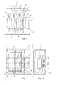
members - The spraying members 19-22 comprise substantially one or more nozzles having a wide opening angle. This is intended to provide for that the cleaner will not be formed into a haze but will be brought onto the rollers in fine droplets. A strongly hazed agent could cause it to deposit against the inside of the housing together with ink particles after all. The orifice of the nozzles has a wide angle, thus excluding dripping. This is important, because dripping of nozzles during the normal printing process will hinder the printed matter.
- Spraying members 19-22 are mounted in
profiles housing 2 of theinking unit 1. Said spraying members 19-22 are provided with supplies and controls of their own in a way not further indicated, which can be for each of the spraying members separately, or per set of sprayingmembers - Fig. 4 illustrates a plan view of the
inking unit 1 having thehousing 2 and alid 25 mounted onhousing 2. Thelid 25 has rows ofopenings openings member 16. -
Underpressure member 16 is incorporated in a connectingprofile 28 by which opposite walls of thehousing 2 are connected. Theunderpressure member 16 comprises twoorifices air pipe 31 is transversely led, having a much smaller diameter than the diameter of the orifices.Air pipe 31 is provided withopenings 32, through which pressurized air is blown out causing an underpressure in the orifices. The underpressure is controlled such, that at the other side ofink filter 18 there is sufficient underpressure for maintaining a particularly uniform air flow.
Claims (20)
- Method of cleaning and keeping clean an inking unit of a printing device, in which for cleaning the successive inking rollers of the inking unit, a cleaner is applied onto the inking rollers, characterized in that the cleaner is applied on at least a part of the rolling length of one inking roller of the ink unit with the help of at least one spraying member, with at least one of the inking rollers being driven and at least part of the cleaning is carried out across corresponding parts of the rolling lengths of successive inking rollers of the inking unit.
- Method according to claim 1, characterized in that for at least two inking rollers, two spraying members per inking roller have been mounted, in which each of the spraying members is arranged to apply cleaner across at least half the rolling length of the inking roller concerned.
- Method according to claim 2, characterized in that a first set of spraying members applies cleaner onto corresponding parts of the rolling lengths of two successive inking rollers and a second set of spraying members applies cleaner on corresponding parts of the rolling lengths of two further successive inking rollers in the inking unit.
- Method according to claim 3, characterized in that the second set of spraying members, with an inking roller transferring the ink onto a higher and a lower further inking roller, are directed at the transferring inking roller and the higher further inking roller.
- Method according to claims 1-4, characterized in that with at least one inking roller, ink and cleaner are scraped across at least a part of the rolling length of the inking roller.
- Method according to claims 1-5, characterized in that the ink duct and the connecting inking roller are cleaned independently of the other inking rollers of the inking unit.
- Method for cleaning an inking unit according to one or more of the preceding claims, as well as keeping the inking unit clean during use of the inking unit, characterized in that the ink mist arising during use or cleaning is extracted.
- Method according to claim 7, characterized in that an air flow for exhausting the ink mist is generated which is led to a filtering member at or near the inking unit from a lateral direction or lateral directions.
- Inking unit for use with the method according to one or more of the preceding claims, characterized in that at a distance above one or more inking rollers of the inking unit, at least two spaced-apart spraying members per inking roller are provided.
- Inking unit according to claim 9, characterized in that the spraying members are controlled independently from one another.
- Inking unit according to claim 10, characterized in that the spraying members are provided with nozzles having a wide opening angle.
- Inking unit according to claims 9-11, characterized in that a scraping member having at least one scraping knife composed of one or more parts is provided, in which in case of a scraping knife composed of a number of parts, the parts can be moved into contact with and away from the inking roller concerned separately.
- Inking unit according to claim 12, characterized in that the scraping member engages a driven inking roller.
- Inking unit for carrying out the method according to claims 7-8, characterized in that the inking rollers of the inking unit are accommodated in a housing extending from near the printing roller with printing cloth to near or across the ink duct, said housing being closed entirely or for the larger part between said outer ends, in which an underpressure member for generating an air flow within the housing is provided at one outer end.
- Inking unit according to claim 14, characterized in that the housing has openings laterally of the effective axial surface of one or more of the successive inking rollers.
- Inking unit according to claims 14-15, characterized in that the underpressure member is mounted near the ink duct.
- Inking unit according to claim 16, characterized in that the underpressure member is mounted at or near a side of the housing being opposite to the side of the housing in which the openings have been made.
- Inking unit according to claims 14-17, characterized in that the underpressure member is provided with one or more orifices in which an outwardly directed air flow is generated.
- Inking unit according to claim 18, characterized in that at least one air pipe for supplying pressurized air, and being provided with one or more openings facing in downstream direction extends in the orifices, transversely to the air flow to be generated.
- Inking unit according to claims 18-19, characterized in that a filter is mounted in front of the orifices of the underpressure member at the upstream side.
Applications Claiming Priority (1)
| Application Number | Priority Date | Filing Date | Title |
|---|---|---|---|
| NL1027297A NL1027297C1 (en) | 2004-10-19 | 2004-10-19 | Method for cleaning or keeping an ink job from a printing device, as well as an ink job adapted thereto. |
Publications (2)
| Publication Number | Publication Date |
|---|---|
| EP1661703A2 true EP1661703A2 (en) | 2006-05-31 |
| EP1661703A3 EP1661703A3 (en) | 2006-06-07 |
Family
ID=36088522
Family Applications (1)
| Application Number | Title | Priority Date | Filing Date |
|---|---|---|---|
| EP05077324A Withdrawn EP1661703A3 (en) | 2004-10-19 | 2005-10-12 | Method of cleaning and keeping clean an inking unit of a printing device and the corresponding ink unit |
Country Status (2)
| Country | Link |
|---|---|
| EP (1) | EP1661703A3 (en) |
| NL (1) | NL1027297C1 (en) |
Citations (10)
| Publication number | Priority date | Publication date | Assignee | Title |
|---|---|---|---|---|
| US5303652A (en) * | 1992-02-13 | 1994-04-19 | Baldwin Technology Corporation | Spray blanket cleaning system |
| US5365849A (en) * | 1992-09-18 | 1994-11-22 | Heidelberger Druckmaschinen Aktiengesellschaft | Device for washing an inking unit provided at a printing press |
| DE29609426U1 (en) * | 1996-05-28 | 1996-08-14 | Heidelberger Druckmasch Ag | Washing device for inking units of printing machines |
| US5732631A (en) * | 1995-06-06 | 1998-03-31 | Man Roland Druckmaschinen Ag | Method and device for cleaning a cylinder of a rotary printing machine |
| EP0928687A1 (en) * | 1997-12-16 | 1999-07-14 | Richard Munz | Printing press blanket cleaner |
| US20020139268A1 (en) * | 2001-03-27 | 2002-10-03 | Emery David Crowell | Apparatus for selectively cleaning a printing press cylinder |
| DE10149843A1 (en) * | 2001-10-10 | 2003-04-17 | Hermeling Gerhard | Covering hood for printing device has stagelessly adjustable air suction device, at least two separate filters in a single receiver, and closing cover to protect printing device |
| US6561095B1 (en) * | 1998-12-31 | 2003-05-13 | Koenig & Bauer Aktiengesellschaft | Device for cleaning a roller |
| US20030167948A1 (en) * | 2002-03-05 | 2003-09-11 | Weitz Martin J. | Method and apparatus for steam cleaning anilox inking rollers |
| EP1502740A2 (en) * | 2003-07-26 | 2005-02-02 | MAN Roland Druckmaschinen AG | Suction device in an inking unit |
-
2004
- 2004-10-19 NL NL1027297A patent/NL1027297C1/en not_active IP Right Cessation
-
2005
- 2005-10-12 EP EP05077324A patent/EP1661703A3/en not_active Withdrawn
Patent Citations (10)
| Publication number | Priority date | Publication date | Assignee | Title |
|---|---|---|---|---|
| US5303652A (en) * | 1992-02-13 | 1994-04-19 | Baldwin Technology Corporation | Spray blanket cleaning system |
| US5365849A (en) * | 1992-09-18 | 1994-11-22 | Heidelberger Druckmaschinen Aktiengesellschaft | Device for washing an inking unit provided at a printing press |
| US5732631A (en) * | 1995-06-06 | 1998-03-31 | Man Roland Druckmaschinen Ag | Method and device for cleaning a cylinder of a rotary printing machine |
| DE29609426U1 (en) * | 1996-05-28 | 1996-08-14 | Heidelberger Druckmasch Ag | Washing device for inking units of printing machines |
| EP0928687A1 (en) * | 1997-12-16 | 1999-07-14 | Richard Munz | Printing press blanket cleaner |
| US6561095B1 (en) * | 1998-12-31 | 2003-05-13 | Koenig & Bauer Aktiengesellschaft | Device for cleaning a roller |
| US20020139268A1 (en) * | 2001-03-27 | 2002-10-03 | Emery David Crowell | Apparatus for selectively cleaning a printing press cylinder |
| DE10149843A1 (en) * | 2001-10-10 | 2003-04-17 | Hermeling Gerhard | Covering hood for printing device has stagelessly adjustable air suction device, at least two separate filters in a single receiver, and closing cover to protect printing device |
| US20030167948A1 (en) * | 2002-03-05 | 2003-09-11 | Weitz Martin J. | Method and apparatus for steam cleaning anilox inking rollers |
| EP1502740A2 (en) * | 2003-07-26 | 2005-02-02 | MAN Roland Druckmaschinen AG | Suction device in an inking unit |
Also Published As
| Publication number | Publication date |
|---|---|
| EP1661703A3 (en) | 2006-06-07 |
| NL1027297C1 (en) | 2006-04-20 |
Similar Documents
| Publication | Publication Date | Title |
|---|---|---|
| EP1826157A1 (en) | Method and device for washing conveyor belts | |
| CN108136768B (en) | The automatic flushing device and its cleaning method of anilox roll | |
| US20030167948A1 (en) | Method and apparatus for steam cleaning anilox inking rollers | |
| JP2005178382A (en) | Roller, cylinder and cleaner of printing plate | |
| EP1250232B1 (en) | Device and method for cleaning a surface of a rotating cylinder, such as a plate cylinder of a printing press or other | |
| KR20180135009A (en) | Tablet printing device and cleaning method | |
| DE19508725A1 (en) | Horizontal-axis drum, for granulation and coating a fluidised-bed charge, | |
| EP0974462B1 (en) | Inking and cleaning devices in a rotary printing machine | |
| CA2940006C (en) | Inkjet-head cleaning device and method | |
| US6557470B1 (en) | Method and apparatus for cleaning a rubber coated cylinder in an offset press | |
| JP2005001243A (en) | Cleaning liquid feeder for cylinder cleaning, brush unit for cleaning cylinder and cylinder cleaning device | |
| KR100838279B1 (en) | Electrostatic printing device and electrostatic printing method | |
| EP1661703A2 (en) | Method of cleaning and keeping clean an inking unit of a printing device and the corresponding ink unit | |
| KR20110000530A (en) | Priming processing method and priming processing device | |
| CN110290699B (en) | Apparatus and method for washing shell eggs | |
| JP2005131620A (en) | Coating device for building board and washing device for coating gun | |
| US6916376B2 (en) | Painting booth, preferably of the electrostatic painting type | |
| JP4365313B2 (en) | Nozzle for washing machine of printing press | |
| CN101954790B (en) | Cleaning unit, treatment solution coating apparatus having the same and cleaning method using the same | |
| JP3564265B2 (en) | Flexographic printing machine | |
| KR20130131924A (en) | A display circuit board cleaning equipment | |
| JP5825263B2 (en) | Belt conveying apparatus and image recording apparatus | |
| WO1995026848A1 (en) | Two-side facing device | |
| JP7216999B2 (en) | Rotary injection device, rotary injection device assembly, fluid injection device, and injection cleaning method | |
| JP2004066165A (en) | Coating head cleaning device and cleaning method |
Legal Events
| Date | Code | Title | Description |
|---|---|---|---|
| PUAI | Public reference made under article 153(3) epc to a published international application that has entered the european phase |
Free format text: ORIGINAL CODE: 0009012 |
|
| PUAL | Search report despatched |
Free format text: ORIGINAL CODE: 0009013 |
|
| AK | Designated contracting states |
Kind code of ref document: A2 Designated state(s): AT BE BG CH CY CZ DE DK EE ES FI FR GB GR HU IE IS IT LI LT LU LV MC NL PL PT RO SE SI SK TR |
|
| AX | Request for extension of the european patent |
Extension state: AL BA HR MK YU |
|
| AK | Designated contracting states |
Kind code of ref document: A3 Designated state(s): AT BE BG CH CY CZ DE DK EE ES FI FR GB GR HU IE IS IT LI LT LU LV MC NL PL PT RO SE SI SK TR |
|
| AX | Request for extension of the european patent |
Extension state: AL BA HR MK YU |
|
| AKX | Designation fees paid | ||
| 17P | Request for examination filed |
Effective date: 20061109 |
|
| RBV | Designated contracting states (corrected) |
Designated state(s): AT BE BG CH CY CZ DE DK EE ES FI FR GB GR HU IE IS IT LI LT LU LV MC NL PL PT RO SE SI SK TR |
|
| REG | Reference to a national code |
Ref country code: DE Ref legal event code: 8566 |
|
| 17Q | First examination report despatched |
Effective date: 20070301 |
|
| STAA | Information on the status of an ep patent application or granted ep patent |
Free format text: STATUS: THE APPLICATION IS DEEMED TO BE WITHDRAWN |
|
| 18D | Application deemed to be withdrawn |
Effective date: 20070912 |