EP1661514B1 - Apparatus and method for diagnostic gas analysis - Google Patents
Apparatus and method for diagnostic gas analysis Download PDFInfo
- Publication number
- EP1661514B1 EP1661514B1 EP06101529A EP06101529A EP1661514B1 EP 1661514 B1 EP1661514 B1 EP 1661514B1 EP 06101529 A EP06101529 A EP 06101529A EP 06101529 A EP06101529 A EP 06101529A EP 1661514 B1 EP1661514 B1 EP 1661514B1
- Authority
- EP
- European Patent Office
- Prior art keywords
- sensor
- sample
- flow rate
- patient
- flow
- Prior art date
- Legal status (The legal status is an assumption and is not a legal conclusion. Google has not performed a legal analysis and makes no representation as to the accuracy of the status listed.)
- Expired - Lifetime
Links
- 238000000034 method Methods 0.000 title claims abstract description 25
- 238000004868 gas analysis Methods 0.000 title description 2
- 238000005259 measurement Methods 0.000 claims abstract description 54
- 239000000463 material Substances 0.000 claims description 3
- 238000004590 computer program Methods 0.000 claims 2
- 230000003197 catalytic effect Effects 0.000 claims 1
- 239000012528 membrane Substances 0.000 claims 1
- 210000002345 respiratory system Anatomy 0.000 claims 1
- 230000035945 sensitivity Effects 0.000 abstract description 9
- MWUXSHHQAYIFBG-UHFFFAOYSA-N Nitric oxide Chemical compound O=[N] MWUXSHHQAYIFBG-UHFFFAOYSA-N 0.000 description 114
- 239000000523 sample Substances 0.000 description 42
- 239000003570 air Substances 0.000 description 24
- 230000006870 function Effects 0.000 description 16
- 230000008901 benefit Effects 0.000 description 11
- 239000007789 gas Substances 0.000 description 10
- 238000004891 communication Methods 0.000 description 7
- 230000029058 respiratory gaseous exchange Effects 0.000 description 6
- 230000004044 response Effects 0.000 description 6
- 239000012080 ambient air Substances 0.000 description 5
- 238000004458 analytical method Methods 0.000 description 5
- 208000037265 diseases, disorders, signs and symptoms Diseases 0.000 description 4
- 239000000126 substance Substances 0.000 description 4
- 230000000007 visual effect Effects 0.000 description 4
- 238000013313 FeNO test Methods 0.000 description 3
- 238000010276 construction Methods 0.000 description 3
- 201000010099 disease Diseases 0.000 description 3
- 239000003814 drug Substances 0.000 description 3
- 238000004519 manufacturing process Methods 0.000 description 3
- 238000012544 monitoring process Methods 0.000 description 3
- 230000037361 pathway Effects 0.000 description 3
- 239000013610 patient sample Substances 0.000 description 3
- 230000008569 process Effects 0.000 description 3
- 230000000241 respiratory effect Effects 0.000 description 3
- 229920000557 Nafion® Polymers 0.000 description 2
- 230000001580 bacterial effect Effects 0.000 description 2
- 230000004397 blinking Effects 0.000 description 2
- 230000037396 body weight Effects 0.000 description 2
- 238000002485 combustion reaction Methods 0.000 description 2
- 150000001875 compounds Chemical class 0.000 description 2
- 230000001276 controlling effect Effects 0.000 description 2
- 230000001419 dependent effect Effects 0.000 description 2
- 238000001514 detection method Methods 0.000 description 2
- 238000002405 diagnostic procedure Methods 0.000 description 2
- 238000009792 diffusion process Methods 0.000 description 2
- 229940079593 drug Drugs 0.000 description 2
- 238000005516 engineering process Methods 0.000 description 2
- 230000036541 health Effects 0.000 description 2
- 239000004973 liquid crystal related substance Substances 0.000 description 2
- 238000012545 processing Methods 0.000 description 2
- 230000002035 prolonged effect Effects 0.000 description 2
- 230000001105 regulatory effect Effects 0.000 description 2
- 230000006641 stabilisation Effects 0.000 description 2
- 238000011105 stabilization Methods 0.000 description 2
- 238000012360 testing method Methods 0.000 description 2
- 210000000115 thoracic cavity Anatomy 0.000 description 2
- OKTJSMMVPCPJKN-UHFFFAOYSA-N Carbon Chemical compound [C] OKTJSMMVPCPJKN-UHFFFAOYSA-N 0.000 description 1
- 206010014415 Electrolyte depletion Diseases 0.000 description 1
- 206010061218 Inflammation Diseases 0.000 description 1
- CBENFWSGALASAD-UHFFFAOYSA-N Ozone Chemical compound [O-][O+]=O CBENFWSGALASAD-UHFFFAOYSA-N 0.000 description 1
- 241000700605 Viruses Species 0.000 description 1
- 230000002159 abnormal effect Effects 0.000 description 1
- 230000003213 activating effect Effects 0.000 description 1
- 239000000654 additive Substances 0.000 description 1
- 239000000443 aerosol Substances 0.000 description 1
- 208000006673 asthma Diseases 0.000 description 1
- 238000007707 calorimetry Methods 0.000 description 1
- 229910052799 carbon Inorganic materials 0.000 description 1
- 239000003086 colorant Substances 0.000 description 1
- 238000012790 confirmation Methods 0.000 description 1
- 239000000356 contaminant Substances 0.000 description 1
- 238000011109 contamination Methods 0.000 description 1
- 238000013500 data storage Methods 0.000 description 1
- 238000007791 dehumidification Methods 0.000 description 1
- 208000035475 disorder Diseases 0.000 description 1
- 230000003203 everyday effect Effects 0.000 description 1
- 208000015181 infectious disease Diseases 0.000 description 1
- 230000004054 inflammatory process Effects 0.000 description 1
- 210000004072 lung Anatomy 0.000 description 1
- 238000012423 maintenance Methods 0.000 description 1
- 239000003550 marker Substances 0.000 description 1
- 238000002156 mixing Methods 0.000 description 1
- 239000000203 mixture Substances 0.000 description 1
- 238000012986 modification Methods 0.000 description 1
- 230000004048 modification Effects 0.000 description 1
- 239000013618 particulate matter Substances 0.000 description 1
- 230000035479 physiological effects, processes and functions Effects 0.000 description 1
- 229920005597 polymer membrane Polymers 0.000 description 1
- 229920000098 polyolefin Polymers 0.000 description 1
- 239000012286 potassium permanganate Substances 0.000 description 1
- 230000000306 recurrent effect Effects 0.000 description 1
- 238000011160 research Methods 0.000 description 1
- 230000000717 retained effect Effects 0.000 description 1
- 230000033764 rhythmic process Effects 0.000 description 1
- 210000001584 soft palate Anatomy 0.000 description 1
- 238000002560 therapeutic procedure Methods 0.000 description 1
- 239000012815 thermoplastic material Substances 0.000 description 1
- 230000007704 transition Effects 0.000 description 1
- 230000003612 virological effect Effects 0.000 description 1
- XLYOFNOQVPJJNP-UHFFFAOYSA-N water Substances O XLYOFNOQVPJJNP-UHFFFAOYSA-N 0.000 description 1
Images
Classifications
-
- A—HUMAN NECESSITIES
- A61—MEDICAL OR VETERINARY SCIENCE; HYGIENE
- A61B—DIAGNOSIS; SURGERY; IDENTIFICATION
- A61B5/00—Measuring for diagnostic purposes; Identification of persons
- A61B5/08—Detecting, measuring or recording devices for evaluating the respiratory organs
- A61B5/0803—Recording apparatus specially adapted therefor
-
- G—PHYSICS
- G01—MEASURING; TESTING
- G01N—INVESTIGATING OR ANALYSING MATERIALS BY DETERMINING THEIR CHEMICAL OR PHYSICAL PROPERTIES
- G01N27/00—Investigating or analysing materials by the use of electric, electrochemical, or magnetic means
- G01N27/26—Investigating or analysing materials by the use of electric, electrochemical, or magnetic means by investigating electrochemical variables; by using electrolysis or electrophoresis
- G01N27/28—Electrolytic cell components
-
- A—HUMAN NECESSITIES
- A61—MEDICAL OR VETERINARY SCIENCE; HYGIENE
- A61B—DIAGNOSIS; SURGERY; IDENTIFICATION
- A61B5/00—Measuring for diagnostic purposes; Identification of persons
- A61B5/08—Detecting, measuring or recording devices for evaluating the respiratory organs
- A61B5/082—Evaluation by breath analysis, e.g. determination of the chemical composition of exhaled breath
-
- A—HUMAN NECESSITIES
- A61—MEDICAL OR VETERINARY SCIENCE; HYGIENE
- A61B—DIAGNOSIS; SURGERY; IDENTIFICATION
- A61B5/00—Measuring for diagnostic purposes; Identification of persons
- A61B5/08—Detecting, measuring or recording devices for evaluating the respiratory organs
- A61B5/097—Devices for facilitating collection of breath or for directing breath into or through measuring devices
-
- A—HUMAN NECESSITIES
- A61—MEDICAL OR VETERINARY SCIENCE; HYGIENE
- A61B—DIAGNOSIS; SURGERY; IDENTIFICATION
- A61B5/00—Measuring for diagnostic purposes; Identification of persons
- A61B5/48—Other medical applications
- A61B5/486—Bio-feedback
-
- A—HUMAN NECESSITIES
- A61—MEDICAL OR VETERINARY SCIENCE; HYGIENE
- A61B—DIAGNOSIS; SURGERY; IDENTIFICATION
- A61B5/00—Measuring for diagnostic purposes; Identification of persons
- A61B5/74—Details of notification to user or communication with user or patient ; user input means
- A61B5/7405—Details of notification to user or communication with user or patient ; user input means using sound
-
- A—HUMAN NECESSITIES
- A61—MEDICAL OR VETERINARY SCIENCE; HYGIENE
- A61B—DIAGNOSIS; SURGERY; IDENTIFICATION
- A61B5/00—Measuring for diagnostic purposes; Identification of persons
- A61B5/74—Details of notification to user or communication with user or patient ; user input means
- A61B5/742—Details of notification to user or communication with user or patient ; user input means using visual displays
-
- G—PHYSICS
- G01—MEASURING; TESTING
- G01N—INVESTIGATING OR ANALYSING MATERIALS BY DETERMINING THEIR CHEMICAL OR PHYSICAL PROPERTIES
- G01N1/00—Sampling; Preparing specimens for investigation
- G01N1/02—Devices for withdrawing samples
- G01N1/22—Devices for withdrawing samples in the gaseous state
-
- G—PHYSICS
- G01—MEASURING; TESTING
- G01N—INVESTIGATING OR ANALYSING MATERIALS BY DETERMINING THEIR CHEMICAL OR PHYSICAL PROPERTIES
- G01N21/00—Investigating or analysing materials by the use of optical means, i.e. using sub-millimetre waves, infrared, visible or ultraviolet light
- G01N21/75—Systems in which material is subjected to a chemical reaction, the progress or the result of the reaction being investigated
- G01N21/76—Chemiluminescence; Bioluminescence
- G01N21/766—Chemiluminescence; Bioluminescence of gases
-
- G—PHYSICS
- G01—MEASURING; TESTING
- G01N—INVESTIGATING OR ANALYSING MATERIALS BY DETERMINING THEIR CHEMICAL OR PHYSICAL PROPERTIES
- G01N33/00—Investigating or analysing materials by specific methods not covered by groups G01N1/00 - G01N31/00
- G01N33/0004—Gaseous mixtures, e.g. polluted air
- G01N33/0009—General constructional details of gas analysers, e.g. portable test equipment
- G01N33/0027—General constructional details of gas analysers, e.g. portable test equipment concerning the detector
- G01N33/0036—Specially adapted to detect a particular component
- G01N33/0037—Specially adapted to detect a particular component for NOx
-
- G—PHYSICS
- G01—MEASURING; TESTING
- G01N—INVESTIGATING OR ANALYSING MATERIALS BY DETERMINING THEIR CHEMICAL OR PHYSICAL PROPERTIES
- G01N33/00—Investigating or analysing materials by specific methods not covered by groups G01N1/00 - G01N31/00
- G01N33/48—Biological material, e.g. blood, urine; Haemocytometers
- G01N33/483—Physical analysis of biological material
- G01N33/497—Physical analysis of biological material of gaseous biological material, e.g. breath
-
- G—PHYSICS
- G01—MEASURING; TESTING
- G01N—INVESTIGATING OR ANALYSING MATERIALS BY DETERMINING THEIR CHEMICAL OR PHYSICAL PROPERTIES
- G01N33/00—Investigating or analysing materials by specific methods not covered by groups G01N1/00 - G01N31/00
- G01N33/0004—Gaseous mixtures, e.g. polluted air
- G01N33/0009—General constructional details of gas analysers, e.g. portable test equipment
- G01N33/0011—Sample conditioning
- G01N33/0016—Sample conditioning by regulating a physical variable, e.g. pressure, temperature
-
- Y—GENERAL TAGGING OF NEW TECHNOLOGICAL DEVELOPMENTS; GENERAL TAGGING OF CROSS-SECTIONAL TECHNOLOGIES SPANNING OVER SEVERAL SECTIONS OF THE IPC; TECHNICAL SUBJECTS COVERED BY FORMER USPC CROSS-REFERENCE ART COLLECTIONS [XRACs] AND DIGESTS
- Y02—TECHNOLOGIES OR APPLICATIONS FOR MITIGATION OR ADAPTATION AGAINST CLIMATE CHANGE
- Y02A—TECHNOLOGIES FOR ADAPTATION TO CLIMATE CHANGE
- Y02A50/00—TECHNOLOGIES FOR ADAPTATION TO CLIMATE CHANGE in human health protection, e.g. against extreme weather
- Y02A50/20—Air quality improvement or preservation, e.g. vehicle emission control or emission reduction by using catalytic converters
-
- Y—GENERAL TAGGING OF NEW TECHNOLOGICAL DEVELOPMENTS; GENERAL TAGGING OF CROSS-SECTIONAL TECHNOLOGIES SPANNING OVER SEVERAL SECTIONS OF THE IPC; TECHNICAL SUBJECTS COVERED BY FORMER USPC CROSS-REFERENCE ART COLLECTIONS [XRACs] AND DIGESTS
- Y10—TECHNICAL SUBJECTS COVERED BY FORMER USPC
- Y10T—TECHNICAL SUBJECTS COVERED BY FORMER US CLASSIFICATION
- Y10T436/00—Chemistry: analytical and immunological testing
- Y10T436/17—Nitrogen containing
- Y10T436/177692—Oxides of nitrogen
- Y10T436/179228—Both nitrogen oxide and dioxide
-
- Y—GENERAL TAGGING OF NEW TECHNOLOGICAL DEVELOPMENTS; GENERAL TAGGING OF CROSS-SECTIONAL TECHNOLOGIES SPANNING OVER SEVERAL SECTIONS OF THE IPC; TECHNICAL SUBJECTS COVERED BY FORMER USPC CROSS-REFERENCE ART COLLECTIONS [XRACs] AND DIGESTS
- Y10—TECHNICAL SUBJECTS COVERED BY FORMER USPC
- Y10T—TECHNICAL SUBJECTS COVERED BY FORMER US CLASSIFICATION
- Y10T436/00—Chemistry: analytical and immunological testing
- Y10T436/25—Chemistry: analytical and immunological testing including sample preparation
- Y10T436/25375—Liberation or purification of sample or separation of material from a sample [e.g., filtering, centrifuging, etc.]
Definitions
- U.S. 2002 077 765 A1 concerns an indirect calorimetry system including transducers sensitive to expired airflow, enclosed in a calorimeter housing, and a microprocessor in communication with the transducers for calculating expiration characteristics.
- U.S. 4,927,517 concerns an NOx sensor having a simplified construction, which is said to be possible to manufacture at a relatively low cost.
- the sensor appears to be intended for determining the concentration of NOx in exhaust gases or emissions produced by automotive internal combustion engines or various industrial furnaces, in order to control the combustion or burning condition of the engines or furnaces.
- One objective of the present invention is to make available a portable, preferably handheld device, for diagnostic determinations of NO. Further aims include the goal to make the device easy to use, robust and reliable, while maintaining the high accuracy and sensitivity of the chemiluminescence analysers.
- a further objective of the present invention is to make available an interface between the parameters dictated by physiological factors (e.g. exhalation flow rate, humidity, temperature etc), parameters dictated by standardized medical or diagnostic procedures (sample flow rate, duration etc), and sensor dependent parameters.
- physiological factors e.g. exhalation flow rate, humidity, temperature etc
- parameters dictated by standardized medical or diagnostic procedures sample flow rate, duration etc
- sensor dependent parameters e.g. the temperature requirements of the sensor, the measurement time necessary for reliable measurements, high and low threshold values for humidity etc.
- One particular objective of the present invention is to make available a device for diagnostic NO-measurements operating with an electrochemical sensor, which device is easily used in the clinics or at point-of-care, however without compromising the accuracy and reliability of the measurements.
- Another objective is to make available a handheld and robust device, preferably also being a relatively low-cost device, again without compromising the accuracy and reliability of the measurements.
- the device comprises at least one NO sensor, such as an electrochemical NO sensor, an inlet/outlet through which a patient inhales NO-free air through a scrubber, and exhales exhaled air at a predetermined flow rate and pressure, a buffer chamber for temporarily storing a portion of the exhaled air, and means for feeding said stored portion of the sample to said NO sensor during a period of time longer than the duration of the exhalation and/or at a flow rate much below the exhalation flow rate.
- the method includes at least the steps and operations corresponding to the above.
- the present inventors have surprisingly shown that an interface can be created between physiologically dictated parameters, as well as parameters dictated by standardized procedures, and the requirements of particular sensors.
- electrochemical sensors have a considerably longer response time than other, hitherto used NO sensors, such as the commonly used chemiluminescence sensors. While a chemiluminescence sensor makes an instantaneous determination of the NO concentration in a gaseous sample, an electrochemical sensor requires longer time for establishing a stable signal. Further, electrochemical sensors suffer from high sensitivity to contaminants, sensitivity to variations in humidity, possible cross sensitivity to water or other compounds, low NO sensitivity, as well as a considerable temperature and flow dependence. If correctly calibrated, chemiluminescence sensors are also highly accurate, down to around ⁇ 1 ppb.
- electrochemical sensors have hitherto not been used for diagnostic NO measurements, i.a. due to their long response time, and their relatively high detection levels (low sensitivity) and interference to other compounds.
- the device has a combined inlet/outlet 1, capable of engaging a disposable filter (not shown) through which the patient first inhales NO-free air via a built-in scrubber 3 removing NO from the ambient air, and then exhales, during which exhalation phase a sample is taken for NO-measurement and led to the sensor.
- a disposable filter not shown
- the patient inhales clean, NO-free air through the mouthpiece / filter, and then exhales through the same filter, into the device.
- the filter thus fills two functions, as it both protects the patient and the device from particulate matter, viruses, bacterial, aerosols etc.
- the disposable filter has the added advantage of preventing spread of infections or patient-to-patient contagion.
- a pressure sensor 2 In the vicinity of the inlet/outlet 1, a pressure sensor 2 is situated.
- the pressure sensor has the function of monitoring the breath, to ensure that the soft palate is closed during exhalation, to ensure that accurate exhalation pressure is maintained (the option of giving feed-back to the patient may be included) and to check that the inhalation of NO-free air is performed through the apparatus, i.e. through the NO-scrubber 3.
- the device also has an inlet 4 for ambient air, leading to said scrubber 3.
- the scrubber in turn is connected via a one-way valve 5 to the inlet/outlet 1, so that the patient can inhale NO-free air, but preventing exhaled air to pass said one-way valve.
- the scrubber may be a conventional chemical NO scrubber, having an inlet and an outlet, and a main body filled with suitable filter media, e.g. a KMnO 4 based filter media, or a carbon based filter with suitable chemical additives.
- suitable filter media e.g. a KMnO 4 based filter media, or a carbon based filter with suitable chemical additives.
- a flow regulator 6 which has the function of controlling the exhalation flow with high accuracy to 20 - 800 ml/s, preferably 50 ml/s ( ⁇ 5 ml/s) when the user adapts to the feedback given by the device.
- Said flow regulator may be a passive flow restrictor, or an active regulator with means for measuring the flow and adjusting elements of said regulator, or by giving feed back to the patient, guiding the exhalation flow.
- the flow regulator automatically adjusts to the exhalation flow, limiting excess flow.
- the flow regulator is capable of adjusting to two or more pre-set levels of flow, during one exhalation, or during two or more subsequent exhalations.
- the exhalation air is then led, through the flow regulator 6, to a buffer chamber 7, at the end of which a flush valve 8, and a three-way valve 9, are situated.
- the flush valve 8 is open, and the three-way valve 9 closed, and the exhaled air is thus led to the ambient atmosphere.
- the flush valve 8 will close, and the three-way valve 9 open, so that the sample stored in the buffer chamber 7 will be led though the three-way valve 9, with the aid of a sample pump or fan 10, to the sensor 11.
- the sensor may be any suitable NO sensor, e.g. a chemical, electrochemical, ultrasonic or other, preferably an electrochemical sensor.
- the sample pump 10 is a plunger pump.
- This type of pump has the advantages of being insensitive to variations in flow, and gives a low, even flow with high accuracy.
- said means 13 acts to temperate both the sample and the sensor, e.g. by surrounding the sensor and by forming a large contact area for the gas flow.
- the temperature of the sample and/or that of the sensor is measured, and the results compensated for the temperature according to the specifications of the sensor.
- the device preferably also comprises means for keeping track of current date and time, as well as means for setting the current date and time.
- an alarm function which can be set for single or recurrent alarms, for example a specific time every day. It is possible to set the alarm time and recurrence, as well as to enable / disable the alarm.
- the alarm function has the advantage of improving patient compliancy with regard to monitoring their condition, and hopefully also with regard to the treatment of the same.
- the input reaching the means 14 consist of signals from the pressure sensor, the NO sensor, the user interface, external communication interfaces, and the temperature control.
- the output leaving the means 14 consist of signals regulating the position of the flush valve, the three-way valve, the sample pump, the temperature control and the user interface.
- the sample of exhalation air is collected in accordance with the standardised exhalation manoeuvre (See ERS Guidelines 1997, ATS Guidelines 1999, supra ) where after it is temporarily stored in a buffer chamber, which makes it possible to expose the sensor to a zero-sample or a patient sample at a steady flow, during a prolonged period of time, in order to obtain an accurate response from the sensor.
- the device includes a buffer chamber, and means for filling said buffer chamber during controlled exhalation, thus taking a sample of exhaled air for NO measurement.
- the volume of said buffer chamber is chosen so that it is sufficient to hold a sample, which then can be delivered to the sensor during a prolonged period of time, e.g. a volume of 150 ml.
- the means for filling said buffer chamber may include a valve or a set of valves.
- the means for filling said buffer chamber with a sample of exhaled air is preferably a valve allowing exhaled air to fill the buffer chamber during a pre-set duration of the exhalation.
- the means for supplying the sample to the sensor preferably consist of a sample pump or fan.
- said means for delivering the sample to the sensor is/are activated.
- Such means include a sample pump or fan, supplying the sensor with a flow of about 0.5 to 15 ml/s, preferably from about 2 to about 10 ml/s during a predetermined time, longer than the exhalation time. This time is set in relation to the properties of the sensor, its sensitivity and configuration. The time can be chosen in an interval of about 15 to about 300 s, and preferably when the flow is about 2 ml/s, the time will be about 30 s or about 50 s, depending on the properties of the sensor.
- said buffer chamber is formed as a long channel with small cross-section, e.g. a maze with a round, elliptic, square or rectangular cross section, e.g. moulded in a block of thermoplastic material.
- said buffer chamber is formed as a length of tubing of a suitable, inert material, such as polyolefine tubing.
- said buffer chamber is formed as a cylinder with a movable end wall or piston.
- sample is aspirated into and displaced out from the cylinder.
- This embodiment can be exemplified by a syringe where the volume of the syringe corresponds to the volume of the sample to be taken, and the rate at which the piston displaces the sample is equal to the rate at which the sample is to be fed to the sensor.
- said buffer chamber is formed as a bellows of a suitable material.
- the sample is allowed to enter the bellows, either by the pressure exerted by the patient when exhaling into the device, or aided by mechanically expanding the bellows.
- the sample is then displaced by mechanically compressing the bellows.
- the buffer chamber is adapted for sequential storage, i.e. the storage of many sequential samples.
- the channel preferably has a geometry which maximizes turbulence in order to minimize mixing due to laminar layers, e.g. a channel with varying cross-section or having deliberate disturbances to flow.
- Electrochemical sensors are known to be sensitive to fluctuations in humidity.
- the device according to the invention preferably includes means for equalising the humidity of the sampled exhalation air, as well as the zero sample, with ambient humidity.
- Such means may consist of a length of NAFION ® tube, through which the sample is led (NAFION ® is a perfluorinated polymer membrane, the trademark being the property of E.I. du Pont de Nemours & Co, Delaware, USA).
- NAFION ® is a perfluorinated polymer membrane, the trademark being the property of E.I. du Pont de Nemours & Co, Delaware, USA.
- the advantage of this lies in that the patient sample and the zero sample will have the same humidity when reaching the sensor.
- the life span of the sensor is subject of a two-fold consideration.
- the device is equipped with means capable of establishing the production date and/or calibration date and/or expiration date of the sensor, e.g. by reading such information stored in association to the sensor, preventing use of the sensor according to pre-set criteria, e.g. when the expiration date is reached.
- the device is further equipped with means for registering the number of measurements performed with a sensor, and preventing use of the sensor according to pre-set criteria, e.g. detection or determination of necessary sensor parameters.
- the device according to the present invention has a novel, greatly simplified visual interface.
- the visual interface comprises a display, which indicates the state of the device (e.g. ON / START UP / READY / BUSY / OFF etc.) and guides the user through the inhalation and/or exhalation, and presents the result of the measurement.
- This display is preferably a conventional display, such as a liquid crystal display (LCD). Most preferably said display is a so called touch screen.
- the above functions can be further supported by visual and audible signals, such as one or more blinking light/-s, user messages on a display, signals consisting of different symbols or colours, an audible signal which changes in tone or rhythm, all depending on the state of the device, or on the performance of the patient when inhaling and/or exhaling.
- visual and audible signals such as one or more blinking light/-s, user messages on a display, signals consisting of different symbols or colours, an audible signal which changes in tone or rhythm, all depending on the state of the device, or on the performance of the patient when inhaling and/or exhaling.
- the device may display one symbol or colour when in START UP mode, and another symbol or colour when the START UP mode is completed, and the device is ready for measurements or enters READY mode.
- the device may display one first symbol or colour, either blinking or steady, when the user inhales and/or exhales incorrectly, and then another second symbol or colour or other signal, clearly distinguishable from said first symbol, colour or signal when the inhalation and/or exhalation is performed according to pre-set requirements, ensuring good repeatability of the measurements.
- Parameters to be controlled and associated to visual and/or audible signals include the duration and pressure of the inhalation, and the exhalation, respectively.
- the device according to the present invention is preferably capable of communicating with its surroundings in many ways. With the patient, the device will communicate audibly and/or visually, indicating basic functions, state of readiness, proper use (inhalation, exhalation) and the result of the measurement. It is possible e.g. to send configuration data between an external software and a smartcard via the device.
- the device preferably includes an IR port for communication with a computer, e.g. for storing patient data in a database, for further analysis of the data or a separate IR printer for measurement report print-out.
- a computer e.g. for storing patient data in a database, for further analysis of the data or a separate IR printer for measurement report print-out.
- the IR port may also work to incorporate the device in a local network, enabling the use of local printers or in other ways to handle measurement results and patient information.
- the NO measurement results would then be recorded on the internal device memory and on the smartcard, together with information regarding the identity of the device and sensor used in the measurement, the date and time of the measurement, and optionally the ambient temperature and humidity.
- the smartcard would be designed to carry the patient history, and NO levels, optionally together with information regarding medication, doses, disease parameters, and subjective information, such the state of health, assessed by the patient or by the treating physician or nurse.
- the device is preferably also capable of communicating with external software, installed on an external computer, such as a PC. It is then possible e.g. to send measurements and other stored data from a smartcard (via the inventive device) to said external software.
- the device according to the present invention may further include an AC/DC converter, preferably an external converted feeding the device with DC.
- the device may further contain a rechargeable battery, a power unit supplying the required voltage to the components of the device.
- a battery for memory and sensor back-up is also included in the system.
- patient configuration is stored on the smartcard.
- the patient information may be general information, relating to different patient groups, such as male/female, child/adult/elderly, and further information, if diagnostically relevant.
- the smartcards are colour coded, each colour corresponding to one patient group.
- the smartcards are printed with a clearly visible number or code, so that individual cards can be distinguished.
- the smartcards have an area where the name of the patient can be printed or hand-written.
- the patient information may also be individual information, relating to a specific patient. In both cases, the information may comprise:
- the internal memory of the device according to the invention is preferably able to store both NO measurements and user input, including input e.g. by manufacturer and information for maintenance personnel.
- the device is able to store errors to said internal memory.
- the electrochemical NO sensor is integrated to a circuit comprising a memory, in the following called "sensor memory”.
- a memory in the following called "sensor memory”.
- This is preferably a memory circuit of EEPROM-type.
- Said sensor memory is capable of communicating and/or interacting with the internal memory and control circuits of the device.
- the inventive device will be capable of indicating when the expiration date of the sensor is approaching, or when the remaining number of measurements reaches a predetermined low value, and alerting the user.
- the device will block further use of the sensor and alert the user.
- the result of the measurement is calculated with account to calibration constants in order to obtain the ppb value.
- the temperature will be considered invalid if it has been outside the controlled temperature range for a preset period of time. If the temperature is invalid for a preset period of time, an error message is issued.
- pressure is always measured relative ambient pressure.
- Ambient pressure is defined as the pressure when the user requests a measurement.
- the pressure is required to be maintained below a value set in the internal configuration memory.
- the pressure is further required to be maintained within max and min values set in the internal configuration memory.
- a warning will be issued if the pressure is not within the range defined by high and low values set in the internal configuration memory.
- the processing phase after a preset transition time, the pressure is required to remain at ambient level.
- the device includes a smartcard interface.
- the smartcard is inserted by the user when activating the device or before a measurement is performed, and is to remain inserted during the entire measurement process. If there is less than 10% free measurement storage capacity on said smartcard, the user will be notified before measurement.
- errors are always logged to database on main board memory. If a patient smartcard is inserted when an error occurs, the error will be logged to smartcard.
- the device and method according to the present invention offers many advantages. Numerous sources of error are avoided, or minimized.
- the correct performance of the inhalation is controlled.
- the pressure check is further supplemented by feedback, guiding the patient to perform a correct inhalation and exhalation, or informing the patient when the inhalation and exhalation was correct, and when the breathing maneuver were insufficient.
- the device and method further have built-in means and functions or operations, which constantly ensure that the electrochemical sensor functions properly.
- One major advantage of the device and method according to the invention is the fact that it becomes possible to take a sample from a patient according to parameters dictated by the physiology of said patient, and according to parameters dictated by standardized procedures valid in medicine and diagnostics, while performing the analysis of the sample according to parameters optimal for the chosen sensor.
Abstract
Description
- The present invention relates to the field of diagnostic gas analysis, and in particular to the determination of endogenous nitric oxide (NO) in exhaled breath of humans.
- The discovery of endogenous NO in exhaled air, and its use as a diagnostic marker of inflammation dates back to the early 1990 (See e.g.
WO 93/05709 WO 95/02181 - In the summer of 1997 the European Respiratory Journal published guidelines (ERS Task Force Report 10:1683-1693) for the standardisation of NO measurements in order to allow their rapid introduction into clinical practice. Also the American Thoracic Society (ATS) has published guidelines for clinical NO measurements (American Thoracic Society, Medical Section of the American Lung Association: Recommendations for standardized procedures for the online and offline measurement of exhaled lower respiratory nitric oxide and nasal nitric oxide in adults and children - 1999, in Am J Respir Crit Care Med, 1999; 160:2104-2117).
- The NIOX® analyser for clinical use, and others mainly intended for research applications, are based on chemiluminescence determination of NO. While highly accurate and reliable, chemiluminescence determination of NO requires an advanced apparatus involving an ozone generator, a vacuum pump, means for dehumidification of the exhaled air, to mention only a few examples. Although the chemiluminescence analysers have developed significantly, they are still rather expensive and bulky.
-
WO 01/26547 - While appealing as a concept, it appears to be practically very difficult if not impossible to achieve accurate and reliable NO determinations in the ppb range using a device according to
WO 01/26547 -
U.S. 5,922,610 relates to a system to be used for measuring NO levels in exhaled breathing air. In the examples, NO was analysed using a chemiluminescence apparatus. -
EP 904 729 -
U.S. 2002 077 765 A1 concerns an indirect calorimetry system including transducers sensitive to expired airflow, enclosed in a calorimeter housing, and a microprocessor in communication with the transducers for calculating expiration characteristics. -
U.S. 4,927,517 concerns an NOx sensor having a simplified construction, which is said to be possible to manufacture at a relatively low cost. The sensor appears to be intended for determining the concentration of NOx in exhaust gases or emissions produced by automotive internal combustion engines or various industrial furnaces, in order to control the combustion or burning condition of the engines or furnaces. -
US 5,922,610 is directed to a system for the determination of NO levels in exhaled air and diagnostic methods for disorders related to abnormal NO levels.US 5,922,610 discloses a device for NO measurements. The device comprises a NO sensor and a mask through which a patient exhales. The device may comprise an elastic reservoir, which is kept inflated during the measurements between breaths. It is taught to divide the exhaled flow into two lines. One line leads to the measuring unit, which may have a flow regulator or valves for regulating the flow. The other line leads excess sample to the ambient air. It is described that the flow to the measuring unit should be less than the average breathing flow rate in order to secure that no contamination from ambient air enter the measuring unit. The part of the flow to the measuring unit is above 5% and preferably lower than 50% of the average breathing rate. - One objective of the present invention is to make available a portable, preferably handheld device, for diagnostic determinations of NO. Further aims include the goal to make the device easy to use, robust and reliable, while maintaining the high accuracy and sensitivity of the chemiluminescence analysers.
- A further objective of the present invention is to make available an interface between the parameters dictated by physiological factors (e.g. exhalation flow rate, humidity, temperature etc), parameters dictated by standardized medical or diagnostic procedures (sample flow rate, duration etc), and sensor dependent parameters. Notably said physiological factors may vary between different individuals, depending on age, sex, bodyweight, and state of health. By the term sensor dependent parameters is hereby meant e.g. the temperature requirements of the sensor, the measurement time necessary for reliable measurements, high and low threshold values for humidity etc.
- One particular objective of the present invention is to make available a device for diagnostic NO-measurements operating with an electrochemical sensor, which device is easily used in the clinics or at point-of-care, however without compromising the accuracy and reliability of the measurements.
- Another objective is to make available a handheld and robust device, preferably also being a relatively low-cost device, again without compromising the accuracy and reliability of the measurements.
- Further objectives, solved by the present invention, and advantages associated therewith will become evident from the following description and examples.
- The objectives of the present invention are met by a device and method according to the attached claims. According to the invention, the device comprises at least one NO sensor, such as an electrochemical NO sensor, an inlet/outlet through which a patient inhales NO-free air through a scrubber, and exhales exhaled air at a predetermined flow rate and pressure, a buffer chamber for temporarily storing a portion of the exhaled air, and means for feeding said stored portion of the sample to said NO sensor during a period of time longer than the duration of the exhalation and/or at a flow rate much below the exhalation flow rate. The method includes at least the steps and operations corresponding to the above.
- The invention will be described in closer detail in the following description, non-limiting examples, and claims, with reference to the attached drawings in which:
-
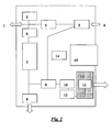
Fig. 1 shows schematically the components of a device according to the invention. - The present inventors have surprisingly shown that an interface can be created between physiologically dictated parameters, as well as parameters dictated by standardized procedures, and the requirements of particular sensors.
- This is illustrated by the device and method according to the present invention as claimed in
claim 1, where electrochemical sensor technology has been successfully applied in diagnostic measurements of NO. - It was however not possible to apply any NO sensor, such as an electrochemical sensor to NO measurements directly. At the present, electrochemical sensors have a considerably longer response time than other, hitherto used NO sensors, such as the commonly used chemiluminescence sensors. While a chemiluminescence sensor makes an instantaneous determination of the NO concentration in a gaseous sample, an electrochemical sensor requires longer time for establishing a stable signal. Further, electrochemical sensors suffer from high sensitivity to contaminants, sensitivity to variations in humidity, possible cross sensitivity to water or other compounds, low NO sensitivity, as well as a considerable temperature and flow dependence. If correctly calibrated, chemiluminescence sensors are also highly accurate, down to around ± 1 ppb.
- Consequently electrochemical sensors have hitherto not been used for diagnostic NO measurements, i.a. due to their long response time, and their relatively high detection levels (low sensitivity) and interference to other compounds.
- As a result of the inventive efforts, it has surprisingly become possible to create a working interface between physiologically dictated parameters, as well as parameters dictated by standardized procedures, and the requirements of particular sensors. This made it possible to apply the electrochemical sensor technology to diagnostic NO measurements where a high reliability and accuracy in the lower ppb range (0 to 200 ppb, in particular in the range of 0 to about 50 ppb) is required, a novel device had to be developed.
- In general terms, the device according to the invention has the following functionality and/or means for performing said functions (see also
Fig. 1 ): - The device has a combined inlet/
outlet 1, capable of engaging a disposable filter (not shown) through which the patient first inhales NO-free air via a built-inscrubber 3 removing NO from the ambient air, and then exhales, during which exhalation phase a sample is taken for NO-measurement and led to the sensor. - Preferably the inlet of the device is designed to tightly engage a disposable patient filter / mouthpiece filter. This filter may be a conventional filter, capable of ensuring viral/bacterial free air during normal inhalation, such as a 0.22 µ filter. The filter is preferably a NIOX® PATIENT FILTER, marketed by Aerocrine AB, Solna, Sweden (Catalogue no. 02-1201).
- The patient inhales clean, NO-free air through the mouthpiece / filter, and then exhales through the same filter, into the device. The filter thus fills two functions, as it both protects the patient and the device from particulate matter, viruses, bacterial, aerosols etc. The disposable filter has the added advantage of preventing spread of infections or patient-to-patient contagion.
- In the vicinity of the inlet/
outlet 1, apressure sensor 2 is situated. The pressure sensor has the function of monitoring the breath, to ensure that the soft palate is closed during exhalation, to ensure that accurate exhalation pressure is maintained (the option of giving feed-back to the patient may be included) and to check that the inhalation of NO-free air is performed through the apparatus, i.e. through the NO-scrubber 3. The device also has aninlet 4 for ambient air, leading to saidscrubber 3. The scrubber in turn is connected via a one-way valve 5 to the inlet/outlet 1, so that the patient can inhale NO-free air, but preventing exhaled air to pass said one-way valve. - The scrubber may be a conventional chemical NO scrubber, having an inlet and an outlet, and a main body filled with suitable filter media, e.g. a KMnO4 based filter media, or a carbon based filter with suitable chemical additives. The construction of the filter, and arrangements for taking a zero sample is the subject of a co-pending patent application.
- Further, in connection to the inlet/
outlet 1 is aflow regulator 6, which has the function of controlling the exhalation flow with high accuracy to 20 - 800 ml/s, preferably 50 ml/s (± 5 ml/s) when the user adapts to the feedback given by the device. Said flow regulator may be a passive flow restrictor, or an active regulator with means for measuring the flow and adjusting elements of said regulator, or by giving feed back to the patient, guiding the exhalation flow. According to one embodiment, the flow regulator automatically adjusts to the exhalation flow, limiting excess flow. According to another embodiment, the flow regulator is capable of adjusting to two or more pre-set levels of flow, during one exhalation, or during two or more subsequent exhalations. - The exhalation air is then led, through the
flow regulator 6, to abuffer chamber 7, at the end of which aflush valve 8, and a three-way valve 9, are situated. During the initial phase of the exhalation, theflush valve 8 is open, and the three-way valve 9 closed, and the exhaled air is thus led to the ambient atmosphere. At a predetermined time, theflush valve 8 will close, and the three-way valve 9 open, so that the sample stored in thebuffer chamber 7 will be led though the three-way valve 9, with the aid of a sample pump orfan 10, to thesensor 11. - The sensor may be any suitable NO sensor, e.g. a chemical, electrochemical, ultrasonic or other, preferably an electrochemical sensor.
- According to a preferred embodiment of the invention, the
sample pump 10 is a plunger pump. This type of pump has the advantages of being insensitive to variations in flow, and gives a low, even flow with high accuracy. - Before reaching the sensor, the sample is preferably led through
means 12 for equalising the humidity of the sample to ambient conditions, and means 13 for equalising the temperature of the sample to the same stabilised temperature as that of the sensor, which, according to an embodiment, is controlled to a set temperature, different from the ambient temperature. - Preferably said means 13 acts to temperate both the sample and the sensor, e.g. by surrounding the sensor and by forming a large contact area for the gas flow. Alternatively, the temperature of the sample and/or that of the sensor is measured, and the results compensated for the temperature according to the specifications of the sensor.
- The device further comprises means for controlling the functions of the above means, such as
control electronics 14, which receive and analyse input e.g. from the sensors, and the user interface, and control the valves and the sample pump. The means 14 will also handle data acquisition, signal processing, data storage, communication with external units, and the user interface. External communication can be performed using one or several of the following options: a memory card or microprocessor card, an EEPROM card, in the following designated "smartcard", IR-communication, BLUETOOTH®, or other form of wireless communication, or via a conventional serial or parallel port. - The provision of a smartcard has among other advantages, the particular advantage that every patient is free to use any device according to the invention, and information relating to the patient will automatically be stored in the device, together with the measurement results. Simultaneously, information relating to the device and sensor will automatically be stored on the smartcard, together with the measurement results. This gives greatly added flexibility, without compromising the documentation requirements in diagnostic applications.
- The device further comprises a
user interface 15, one component of which has the form of a display, such as a liquid crystal display (LCD), preferably a touch screen, for displaying data to the user, and for receiving commands and settings from the user, e.g. for programming and/or parameter setting, functionality check or similar, performed by a qualified user, or by specifically designated service staff. Alternatively, these functions or part thereof may be performed through a conventional PC-interface, e.g. a conventional serial port (e.g. a USB port), or a parallel port. - The device preferably also comprises means for keeping track of current date and time, as well as means for setting the current date and time. There is preferably also an alarm function, which can be set for single or recurrent alarms, for example a specific time every day. It is possible to set the alarm time and recurrence, as well as to enable / disable the alarm. The alarm function has the advantage of improving patient compliancy with regard to monitoring their condition, and hopefully also with regard to the treatment of the same.
- In summary, the input reaching the
means 14 consist of signals from the pressure sensor, the NO sensor, the user interface, external communication interfaces, and the temperature control. The output leaving themeans 14 consist of signals regulating the position of the flush valve, the three-way valve, the sample pump, the temperature control and the user interface. - In the device according to the invention, the sample of exhalation air is collected in accordance with the standardised exhalation manoeuvre (See ERS Guidelines 1997, ATS Guidelines 1999, supra) where after it is temporarily stored in a buffer chamber, which makes it possible to expose the sensor to a zero-sample or a patient sample at a steady flow, during a prolonged period of time, in order to obtain an accurate response from the sensor.
- The device according to the invention includes a buffer chamber, and means for filling said buffer chamber during controlled exhalation, thus taking a sample of exhaled air for NO measurement. The volume of said buffer chamber is chosen so that it is sufficient to hold a sample, which then can be delivered to the sensor during a prolonged period of time, e.g. a volume of 150 ml. The means for filling said buffer chamber may include a valve or a set of valves. The means for filling said buffer chamber with a sample of exhaled air is preferably a valve allowing exhaled air to fill the buffer chamber during a pre-set duration of the exhalation.
- The means for supplying the sample to the sensor preferably consist of a sample pump or fan.
- Further, there are means for supplying NO-free air to the sensor, said means preferably consisting of a pump or fan, drawing air through a NO-scrubber. This pump or fan may be identical to that supplying the sample to the sensor, the source of gas (patient sample / zero sample) being controlled by one or several valves.
- When the buffer chamber is filled with the desired sample, said means for delivering the sample to the sensor is/are activated. Such means include a sample pump or fan, supplying the sensor with a flow of about 0.5 to 15 ml/s, preferably from about 2 to about 10 ml/s during a predetermined time, longer than the exhalation time. This time is set in relation to the properties of the sensor, its sensitivity and configuration. The time can be chosen in an interval of about 15 to about 300 s, and preferably when the flow is about 2 ml/s, the time will be about 30 s or about 50 s, depending on the properties of the sensor.
- The buffer chamber is a space for temporarily storing a portion of exhaled breath, in order to deliver it to the sensor at a flow and during a duration of time, adapted to the response time of said sensor. Preferably said buffer chamber is a space, which meets at least one of the following requirements:
- no significant diffusion of NO into the walls of the buffer chamber
- no significant diffusion of substances which interfere with the NO measurement
- turbulent flow
- no significant adhesion of NO to the inner walls
- According to one embodiment of the invention, said buffer chamber is formed as a long channel with small cross-section, e.g. a maze with a round, elliptic, square or rectangular cross section, e.g. moulded in a block of thermoplastic material.
- According to another embodiment, said buffer chamber is formed as a length of tubing of a suitable, inert material, such as polyolefine tubing.
- According to yet another embodiment, said buffer chamber is formed as a cylinder with a movable end wall or piston. By operating said end wall or piston longitudinally, sample is aspirated into and displaced out from the cylinder. This embodiment can be exemplified by a syringe where the volume of the syringe corresponds to the volume of the sample to be taken, and the rate at which the piston displaces the sample is equal to the rate at which the sample is to be fed to the sensor.
- According to yet another embodiment, said buffer chamber is formed as a bellows of a suitable material. The sample is allowed to enter the bellows, either by the pressure exerted by the patient when exhaling into the device, or aided by mechanically expanding the bellows. The sample is then displaced by mechanically compressing the bellows.
- According to another embodiment, the buffer chamber is adapted for sequential storage, i.e. the storage of many sequential samples. The channel preferably has a geometry which maximizes turbulence in order to minimize mixing due to laminar layers, e.g. a channel with varying cross-section or having deliberate disturbances to flow.
- In the determination of nitric oxide concentration using an electrochemical sensor, both the temperature of the sensor and the gas flow are critical factors. The temperature of the sensor influences its sensitivity, and consequently fluctuating temperatures between separate measurements will result in poor repeatability and reduced precision and /or accuracy. Correspondingly, the temperature of the gas flow, as it meets the surface of the sensor, will influence the temperature of the sensor, with the above consequences.
- In the device according to the present invention, and in the corresponding method, the temperature may be registered, and the results adjusted to the temperature using a correlation factor. Preferably, the temperature of both the gas and the sensor is accurately controlled by enclosing the sensor in means which both temperate the sensor and the sample gas before it reaches the sensor. The construction of such means is the subject of a co-pending patent application.
- Electrochemical sensors are known to be sensitive to fluctuations in humidity. The device according to the invention preferably includes means for equalising the humidity of the sampled exhalation air, as well as the zero sample, with ambient humidity. Such means may consist of a length of NAFION® tube, through which the sample is led (NAFION® is a perfluorinated polymer membrane, the trademark being the property of E.I. du Pont de Nemours & Co, Delaware, USA). The advantage of this lies in that the patient sample and the zero sample will have the same humidity when reaching the sensor.
- Electrochemical sensors unfortunately tend to have a limited life span, due to the electrolyte depletion.
- According to the method and device of the present invention, the life span of the sensor is subject of a two-fold consideration. The device is equipped with means capable of establishing the production date and/or calibration date and/or expiration date of the sensor, e.g. by reading such information stored in association to the sensor, preventing use of the sensor according to pre-set criteria, e.g. when the expiration date is reached.
- The device is further equipped with means for registering the number of measurements performed with a sensor, and preventing use of the sensor according to pre-set criteria, e.g. detection or determination of necessary sensor parameters.
- The above means and associated functions have the advantage of making it possible to guarantee that each measurement is performed with a well functioning sensor.
- The device according to the present invention has a novel, greatly simplified visual interface. The visual interface comprises a display, which indicates the state of the device (e.g. ON / START UP / READY / BUSY / OFF etc.) and guides the user through the inhalation and/or exhalation, and presents the result of the measurement. This display is preferably a conventional display, such as a liquid crystal display (LCD). Most preferably said display is a so called touch screen.
- The above functions can be further supported by visual and audible signals, such as one or more blinking light/-s, user messages on a display, signals consisting of different symbols or colours, an audible signal which changes in tone or rhythm, all depending on the state of the device, or on the performance of the patient when inhaling and/or exhaling. For example, the device may display one symbol or colour when in START UP mode, and another symbol or colour when the START UP mode is completed, and the device is ready for measurements or enters READY mode. Likewise, the device may display one first symbol or colour, either blinking or steady, when the user inhales and/or exhales incorrectly, and then another second symbol or colour or other signal, clearly distinguishable from said first symbol, colour or signal when the inhalation and/or exhalation is performed according to pre-set requirements, ensuring good repeatability of the measurements. Parameters to be controlled and associated to visual and/or audible signals include the duration and pressure of the inhalation, and the exhalation, respectively.
- The above means and associated functionalities make the device suitable for use by all patients, either alone or under the supervision of medical personnel, e.g. their treating physician or a nurse, for point-of-care use, as well as for home use by individual patients, monitoring their disease.
- The device according to the present invention is preferably capable of communicating with its surroundings in many ways. With the patient, the device will communicate audibly and/or visually, indicating basic functions, state of readiness, proper use (inhalation, exhalation) and the result of the measurement. It is possible e.g. to send configuration data between an external software and a smartcard via the device.
- Further, the device preferably includes an IR port for communication with a computer, e.g. for storing patient data in a database, for further analysis of the data or a separate IR printer for measurement report print-out. The IR port may also work to incorporate the device in a local network, enabling the use of local printers or in other ways to handle measurement results and patient information.
- The device according to the invention preferably also includes a smartcard interface for entering and storing individual patient data. When using the device outside a clinical setting, each user would be given a personal smartcard. Preferably the smartcards would be pre-programmed to contain the settings relevant for different patient groups, e.g. male, female, child, or the settings relevant to patients of different race, age or bodyweight, in order to account for differences in dead space, or other physiologic differences.
- The NO measurement results would then be recorded on the internal device memory and on the smartcard, together with information regarding the identity of the device and sensor used in the measurement, the date and time of the measurement, and optionally the ambient temperature and humidity. According to one embodiment, the smartcard would be designed to carry the patient history, and NO levels, optionally together with information regarding medication, doses, disease parameters, and subjective information, such the state of health, assessed by the patient or by the treating physician or nurse.
- According to another embodiment, the smartcard is configured while inserted in the device but using external software.
- The device is preferably also capable of communicating with external software, installed on an external computer, such as a PC. It is then possible e.g. to send measurements and other stored data from a smartcard (via the inventive device) to said external software.
- According to one embodiment, it is also possible to send measurement data and other stored data from the internal memory of the device to external software.
- Likewise, according to another embodiment, it is also possible to download software updates to the inventive device from external software.
- It is preferably further possible to send service and support parameters, such as an error log from the inventive device to external software.
- The device according to the present invention may further include an AC/DC converter, preferably an external converted feeding the device with DC. The device may further contain a rechargeable battery, a power unit supplying the required voltage to the components of the device. A battery for memory and sensor back-up is also included in the system.
- The device according to the invention preferably comprises an internal memory, preferably with the possibility to store data from at least 2000 measurements. Alternatively, or in addition to the internal memory, the device will be capable of recording information on a removable data medium, such as a so called smartcard, a memory card, a microprocessor card, an EEPROM, a mini disc, diskette, or the like. The data to be recorded in the internal memory and/or on a smartcard or similar may comprise:
- patient ID
- date and time of measurement
- measured FENO
- sensor ID No.
- device ID No.
- disease and comfort parameter inputs in an advanced operating mode
- medication parameter inputs in an advanced operating mode Optionally, when measurement data memory is full, a warning is issued and, following confirmation of said warning, the oldest data may be overwritten with new data.
- Preferably also an error list is provided either in the internal memory, or on the smartcard, or in duplicate on both of these, consisting of at least the following entries:
- error number
- timestamp
- According to a preferred embodiment, patient configuration is stored on the smartcard. The patient information may be general information, relating to different patient groups, such as male/female, child/adult/elderly, and further information, if diagnostically relevant. Preferably the smartcards are colour coded, each colour corresponding to one patient group. Preferably the smartcards are printed with a clearly visible number or code, so that individual cards can be distinguished. Preferably the smartcards have an area where the name of the patient can be printed or hand-written.
- The patient information may also be individual information, relating to a specific patient. In both cases, the information may comprise:
- recommended max FENO value
- recommended min FENO value
- one of the available patient age group modes (via chosen smartcard)
- The internal memory of the device according to the invention is preferably able to store both NO measurements and user input, including input e.g. by manufacturer and information for maintenance personnel. For example, the device is able to store errors to said internal memory.
- The device is preferably also able to store configuration parameters to the internal memory, such as:
- production date
- calibration date
- sensor input calibration parameters
- The device is preferably also able to store settings and operating parameters to the internal memory, such as:
- top LED intensity
- volume
- contrast
- alarm time
- current time and date
- According to a preferred embodiment, the electrochemical NO sensor is integrated to a circuit comprising a memory, in the following called "sensor memory". This is preferably a memory circuit of EEPROM-type. Said sensor memory is capable of communicating and/or interacting with the internal memory and control circuits of the device.
- In other words, it will be possible to read data from the sensor memory, such as:
- sensor calibration data
- expiration date
- sensor depletion control parameters
- sensor integrity data
- It is also possible to count down the remaining number of measurements on sensor at the rate at which measurements are performed.
- According to a preferred embodiment, the inventive device will be capable of indicating when the expiration date of the sensor is approaching, or when the remaining number of measurements reaches a predetermined low value, and alerting the user. When the expiration date is reached, or when the number of measurements exhausted, the device will block further use of the sensor and alert the user.
- According to the invention, the device keeps track of current time and date. It will also be possible to set current time and date, and current time and date is retained during backup battery operation.
- There are numerous advantages related to the provision of a sensor memory. One is safety, as the expiration date will be automatically checked, and the use of the sensor automatically blocked when this date is passed. Another safety issue is the automatic control of the number of measurement, where the use of the sensor is automatically blocked when a maximum number of measurements is reached.
- There may also be provided a feature for measuring ambient NO levels with the device. The ambient measurement process may consist of ambient stabilization, ambient measure, zero stabilization and zero measure phases in mentioned order. The process is similar to that of the diagnostic NO measurement, with the exception that the sample pump is used to extract the sample directly from the ambient air.
- The result of the measurement is calculated with account to calibration constants in order to obtain the ppb value.
- The device according to the invention preferably includes means and functions for temperature control. According to one embodiment, the means for temperature control consist of a Peltier element. The sensor temperature is kept at value set in internal configuration memory: If the measured temperature is outside the set conditions for use, the element will be off.
- The temperature will be considered invalid if it has been outside the controlled temperature range for a preset period of time. If the temperature is invalid for a preset period of time, an error message is issued.
- According to the invention, pressure is always measured relative ambient pressure. Ambient pressure is defined as the pressure when the user requests a measurement. During a preset duration of the inhalation, the pressure is required to be maintained below a value set in the internal configuration memory. During the exhalation phase, the pressure is further required to be maintained within max and min values set in the internal configuration memory. During the exhalation phase, a warning will be issued if the pressure is not within the range defined by high and low values set in the internal configuration memory. During the processing phase, after a preset transition time, the pressure is required to remain at ambient level.
- According to one embodiment, the device includes a smartcard interface. The smartcard is inserted by the user when activating the device or before a measurement is performed, and is to remain inserted during the entire measurement process. If there is less than 10% free measurement storage capacity on said smartcard, the user will be notified before measurement.
- The device and method according to the invention preferably also comprises a self-test function. If self-test fails an error message will be issued.
- According to one embodiment, errors are always logged to database on main board memory. If a patient smartcard is inserted when an error occurs, the error will be logged to smartcard.
- Importantly, the user will be notified when an error occurs.
- The device and method according to the present invention offers many advantages. Numerous sources of error are avoided, or minimized.
- For example, as the device registers the negative pressure when a patient inhales through the device, and thus through the NO scrubber supplying NO free air, the correct performance of the inhalation is controlled. The pressure check is further supplemented by feedback, guiding the patient to perform a correct inhalation and exhalation, or informing the patient when the inhalation and exhalation was correct, and when the breathing maneuver were insufficient.
- The device and method further have built-in means and functions or operations, which constantly ensure that the electrochemical sensor functions properly.
- One major advantage of the device and method according to the invention is the fact that it becomes possible to take a sample from a patient according to parameters dictated by the physiology of said patient, and according to parameters dictated by standardized procedures valid in medicine and diagnostics, while performing the analysis of the sample according to parameters optimal for the chosen sensor.
- This is here illustrated by a device for the analysis of NO in exhaled breath using an electrochemical sensor, but the present invention is also applicable to the analysis of NO or other components, in samples other than exhaled air.
- Although the invention has been described with regard to its preferred embodiments, which constitute the best mode presently known to the inventors, it should be understood that various changes and modifications as would be obvious to one having the ordinary skill in this art may be made without departing from the scope of the invention as set forth in the claims appended hereto.
Claims (25)
- A device for diagnostic NO measurements, which device comprises a NO sensor (11), control electronics (14) an inlet (1) through which a patient exhales at a predetermined first flow rate and pressure, a buffer chamber (7) for temporarily storing a portion of the exhaled air, and means (10) for feeding said portion of the sample to said NO sensor at a second flow rate suitable for said sensor, said second flow rate being lower than said first flow rate, wherein said means for feeding said portion of said sample to said NO sensor comprises at least one device selected from the group consisting of a pump and a fan.
- The device according to claim 1, wherein the device comprises a flow regulator (6) for controlling the exhalation flow and establishing a first flow rate.
- The device according to claim 1, wherein the means (10) for feeding said portion of the sample to said NO sensor operates to create a second steady flow of about 0.5 to 10 ml/s during a time period longer than the duration of the exhalation.
- The device according to claim 1, wherein the device comprises means (12) for equalizing the humidity of the sample.
- The device according to claim 4, wherein said means for equalizing the humidity of the sample consist of a length of tube, made from a catalytic membrane material.
- The device according to claim 1, wherein the device comprises means for verifying the parameters of the inhalation and controlling the parameters of exhalation.
- The device according to claim 6, wherein said means comprise a pressure sensor (2) and means for giving feedback to the patient.
- The device according to claim 6, wherein said means further comprise a flow sensor and means for controlling the flow and/or giving feedback to the patient.
- The device according to claim 6, wherein said means further comprise a pressure sensor (2) capable of measuring absolute pressure in order to make it possible to compensate for varying partial pressure of NO depending on variations in ambient pressure.
- The device according to claim 1, wherein the buffer chamber (7) is a maze.
- The device according to claim 1, wherein the buffer chamber (7) consists of a cylinder with a movable piston.
- The device according to claim 1, wherein the buffer chamber (7) consists of a length of tube.
- The device according to claim 1, wherein the device comprises a NO-scrubber through which a patient inhales directly prior to exhaling into the device, thus ensuring that the dead space of the respiratory tract of the patient is filled with NO-free air.
- The device according to claim 1, wherein the device further comprises an interface for receiving a smartcard on which data linked to a specific user can be stored, and onto which measurement data can be recorded.
- The device according to claim 14, wherein the device is capable of adapting to different users or different user groups, based on the data stored on the smartcard.
- The device according to claim 3, wherein the means (10) for feeding the sample to the NO sensor is a plunger pump
- The device according to claim 3, wherein the means (10) for feeding the sample to the NO sensor is a fan.
- The device according to claim 1, wherein said NO sensor is an electrochemical sensor.
- A method for measuring exhaled NO using a device according to claim 1, characterized in that:- a sample of exhaled air is collected at a first preset flow rate and pressure and temporarily stored in a buffer chamber,- said sample is fed to said NO sensor at a second flow rate suitable for said sensor, and- the NO concentration is determined in said sample.
- The method according to claim 19, wherein said second flow rate is lower than said first flow rate.
- The method according to claim 19, wherein said second flow rate is a steady flow of about 0.5 to 10 ml/s during a time period longer than the duration of the exhalation.
- The method according to claim 19, wherein said first flow rate is in the interval of about 20 to 800 ml/s and said second flow rate is in the interval of about 0.5 to 10 ml/s.
- The method according to claim 19, wherein said NO sensor is an electrochemical sensor.
- A computer program comprising the instructions for performing the method according to any one of the claims 19 through 23.
- The computer program according to claim 24, when stored on a medium.
Applications Claiming Priority (3)
| Application Number | Priority Date | Filing Date | Title |
|---|---|---|---|
| SE0202742A SE0202742D0 (en) | 2002-09-16 | 2002-09-16 | Apparatus and method for diagnostic gas analysis |
| SE0202906A SE0202906D0 (en) | 2002-10-02 | 2002-10-02 | Apparatus and method for diagnostic gas analysis |
| EP03770978A EP1439781B9 (en) | 2002-09-16 | 2003-09-11 | Apparatus for diagnostic gas analysis |
Related Parent Applications (1)
| Application Number | Title | Priority Date | Filing Date |
|---|---|---|---|
| EP03770978A Division EP1439781B9 (en) | 2002-09-16 | 2003-09-11 | Apparatus for diagnostic gas analysis |
Publications (3)
| Publication Number | Publication Date |
|---|---|
| EP1661514A2 EP1661514A2 (en) | 2006-05-31 |
| EP1661514A3 EP1661514A3 (en) | 2006-08-30 |
| EP1661514B1 true EP1661514B1 (en) | 2008-07-23 |
Family
ID=31996346
Family Applications (2)
| Application Number | Title | Priority Date | Filing Date |
|---|---|---|---|
| EP03770978A Expired - Lifetime EP1439781B9 (en) | 2002-09-16 | 2003-09-11 | Apparatus for diagnostic gas analysis |
| EP06101529A Expired - Lifetime EP1661514B1 (en) | 2002-09-16 | 2003-09-11 | Apparatus and method for diagnostic gas analysis |
Family Applications Before (1)
| Application Number | Title | Priority Date | Filing Date |
|---|---|---|---|
| EP03770978A Expired - Lifetime EP1439781B9 (en) | 2002-09-16 | 2003-09-11 | Apparatus for diagnostic gas analysis |
Country Status (11)
| Country | Link |
|---|---|
| US (4) | US7846739B2 (en) |
| EP (2) | EP1439781B9 (en) |
| JP (1) | JP4472533B2 (en) |
| CN (2) | CN1681435B (en) |
| AT (2) | ATE401825T1 (en) |
| AU (1) | AU2003259001B2 (en) |
| CA (1) | CA2495678C (en) |
| DE (3) | DE60322446D1 (en) |
| ES (2) | ES2311264T3 (en) |
| HK (1) | HK1083999A1 (en) |
| WO (1) | WO2004023997A1 (en) |
Cited By (3)
| Publication number | Priority date | Publication date | Assignee | Title |
|---|---|---|---|---|
| DE102012109026A1 (en) * | 2012-09-25 | 2014-03-27 | Eads Deutschland Gmbh | Detection device and detection method for the automatic determination of biomass |
| US10307080B2 (en) | 2014-03-07 | 2019-06-04 | Spirosure, Inc. | Respiratory monitor |
| US11300552B2 (en) | 2017-03-01 | 2022-04-12 | Caire Diagnostics Inc. | Nitric oxide detection device with reducing gas |
Families Citing this family (109)
| Publication number | Priority date | Publication date | Assignee | Title |
|---|---|---|---|---|
| ATE401825T1 (en) * | 2002-09-16 | 2008-08-15 | Aerocrine Ab | APPARATUS AND METHOD FOR DIAGNOSTIC GAS ANALYSIS |
| US8021308B2 (en) | 2003-06-19 | 2011-09-20 | Capnia, Inc. | Breath end-tidal gas monitor |
| FR2858236B1 (en) | 2003-07-29 | 2006-04-28 | Airox | DEVICE AND METHOD FOR SUPPLYING RESPIRATORY GAS IN PRESSURE OR VOLUME |
| US20060036138A1 (en) * | 2004-08-06 | 2006-02-16 | Adam Heller | Devices and methods of screening for neoplastic and inflammatory disease |
| JP4530212B2 (en) * | 2004-09-28 | 2010-08-25 | 株式会社タニタ | Breath analysis device |
| US20060177889A1 (en) * | 2005-02-05 | 2006-08-10 | Aperon Biosystems Corp. | Rapid responding gas sensing element |
| DE102005006111A1 (en) * | 2005-02-10 | 2006-08-24 | Roche Diagnostics Gmbh | Method of controlling the functions of diagnostic apparatus to reduce faulty operation especially in apparatus for measuring blood glucose concentration |
| US20060200037A1 (en) * | 2005-03-02 | 2006-09-07 | Falasco Marianne R | System and method for selectively collecting exhaled air |
| EP1871221B1 (en) * | 2005-04-18 | 2017-11-15 | GPX Medical AB | Human cavity gas measurement device and method |
| JP2007000444A (en) * | 2005-06-24 | 2007-01-11 | Ngk Spark Plug Co Ltd | Breathing state monitoring device, base device, control system, and method of using control system |
| US8903474B2 (en) * | 2005-12-06 | 2014-12-02 | Pen Inc. | Analysis of gases |
| US20070240987A1 (en) * | 2006-04-14 | 2007-10-18 | Nair Balakrishnan G | Apparatus and Method for Measuring Nitric Oxide in Exhaled Breath |
| JP4851847B2 (en) * | 2006-05-30 | 2012-01-11 | 株式会社東芝 | Biological information measuring device |
| AU2007351779A1 (en) * | 2006-09-14 | 2008-10-30 | The Research Foundation of State Univesity of New York | Detecting nitric oxide |
| DE102007012210B4 (en) | 2007-03-08 | 2009-10-15 | Filt Lungen- Und Thoraxdiagnostik Gmbh | Portable pneumotachograph for measuring components of the expiratory volume and a method for this |
| WO2008106961A2 (en) | 2007-03-08 | 2008-09-12 | Filt Lungen- Und Thoraxdiagnostik Gmbh | Portable pneumotachograph for measuring components of an expiration volume, and method therefor |
| WO2008133867A1 (en) * | 2007-04-26 | 2008-11-06 | Merck & Co., Inc. | 2-substituted indole derivatives as calcium channel blockers |
| DE102007032541A1 (en) * | 2007-07-12 | 2009-01-15 | Siemens Ag | Medical device with a device that is designed for the examination and / or treatment of at least one patient, and associated method |
| GB0717433D0 (en) * | 2007-09-07 | 2007-10-17 | Bedfont Scient Ltd | Apparatus and method |
| US8425428B2 (en) * | 2008-03-31 | 2013-04-23 | Covidien Lp | Nitric oxide measurements in patients using flowfeedback |
| US8486346B2 (en) * | 2008-05-19 | 2013-07-16 | Abbott Laboratories | Gas scrubber for automated clinical analyzer |
| DE102008027630A1 (en) * | 2008-06-05 | 2009-12-10 | Filt Lungen- Und Thoraxdiagnostik Gmbh | Portable pneumotachograph for measuring components of the expiratory volume |
| KR20110063442A (en) * | 2008-09-03 | 2011-06-10 | 테스토 아게 | Method for capturing measurement values and displaying measurement values |
| CN101368927B (en) * | 2008-09-08 | 2011-10-19 | 无锡尚沃生物科技有限公司 | Self-calibration gas sensor |
| US8652064B2 (en) * | 2008-09-30 | 2014-02-18 | Covidien Lp | Sampling circuit for measuring analytes |
| US8302602B2 (en) | 2008-09-30 | 2012-11-06 | Nellcor Puritan Bennett Llc | Breathing assistance system with multiple pressure sensors |
| ITRM20080525A1 (en) * | 2008-10-02 | 2010-04-03 | Istituto Superiore Per La Prevenzio Ne E La Sicure | INSTRUMENT FOR THE MEASUREMENT OF KINETIC EXPANSION AND ITS DEPOSITION IN THE AIRWAYS |
| CN102300502A (en) | 2008-12-01 | 2011-12-28 | 创控生技股份有限公司 | Breath Analysis Systems And Methods For Asthma, Tuberculosis And Lung Cancer Diagnostics And Disease Management |
| GB0902880D0 (en) * | 2009-02-20 | 2009-04-08 | Bedfont Scient Ltd | Apparatus and method |
| US8434479B2 (en) | 2009-02-27 | 2013-05-07 | Covidien Lp | Flow rate compensation for transient thermal response of hot-wire anemometers |
| US8206311B2 (en) * | 2009-04-01 | 2012-06-26 | Aerocrine Ab | Analyzer for nitric oxide in exhaled breath with multiple-use sensor |
| WO2010120891A2 (en) * | 2009-04-17 | 2010-10-21 | Linshom L.P. | System and method for monitoring breathing |
| US8911380B1 (en) | 2009-04-17 | 2014-12-16 | Linshom, L.P. | Respiration monitoring system and method |
| DE102009038238A1 (en) * | 2009-08-20 | 2011-02-24 | Siemens Aktiengesellschaft | Sensor platform for respiratory gas analysis |
| US8439036B2 (en) | 2009-12-01 | 2013-05-14 | Covidien Lp | Exhalation valve assembly with integral flow sensor |
| US8469031B2 (en) | 2009-12-01 | 2013-06-25 | Covidien Lp | Exhalation valve assembly with integrated filter |
| US8469030B2 (en) | 2009-12-01 | 2013-06-25 | Covidien Lp | Exhalation valve assembly with selectable contagious/non-contagious latch |
| US8439037B2 (en) | 2009-12-01 | 2013-05-14 | Covidien Lp | Exhalation valve assembly with integrated filter and flow sensor |
| JP5299644B2 (en) * | 2010-01-14 | 2013-09-25 | 株式会社デンソー | Alcohol detector |
| JP5187596B2 (en) * | 2010-01-28 | 2013-04-24 | 株式会社デンソー | Alcohol detector |
| GB201003190D0 (en) * | 2010-02-25 | 2010-04-14 | Bedfont Scient Ltd | Apparatus and method |
| EP2383008B1 (en) * | 2010-04-30 | 2013-11-06 | General Electric Company | Arrangement for maintaining volume of breathing gas in a desired level |
| US9988691B2 (en) | 2010-07-06 | 2018-06-05 | Deton Corp. | System for airborne bacterial sample collection and analysis |
| TW201219010A (en) * | 2010-11-05 | 2012-05-16 | Univ Nat Cheng Kung | Portable asthma detection device and stand-alone portable asthma detection device |
| CN103458783B (en) * | 2011-01-25 | 2015-11-25 | 皇家飞利浦有限公司 | Heaterless based on the CO 2 measuring of lead selenide and/or the system and method for capnography for performing |
| EP2701593B1 (en) * | 2011-04-26 | 2015-06-17 | Koninklijke Philips N.V. | Mainstream gas analyzer configurable to removably couple with a sidestream gas sampling component |
| US9629971B2 (en) | 2011-04-29 | 2017-04-25 | Covidien Lp | Methods and systems for exhalation control and trajectory optimization |
| BE1020244A3 (en) | 2011-05-26 | 2013-07-02 | Medi Soft S A | APPARATUS FOR DIAGNOSTIC ANALYSIS OF NITRIC OXIDE |
| WO2013026902A1 (en) | 2011-08-23 | 2013-02-28 | Aerocrine Ab | Devices and methods for generating an artificial exhalation profile |
| US9364624B2 (en) | 2011-12-07 | 2016-06-14 | Covidien Lp | Methods and systems for adaptive base flow |
| US9310346B1 (en) * | 2011-12-15 | 2016-04-12 | Picarro, Inc. | Methods for rapid gas sampling with high horizontal spatial resolution in a manner suitable for subsequent constituent gas analysis |
| EP2606820B1 (en) * | 2011-12-19 | 2019-10-30 | General Electric Company | Airway adapter and analyzer and method for analyzing at least one property of a respiratory gas |
| CN108132331A (en) | 2011-12-21 | 2018-06-08 | 卡普尼亚公司 | The gas of the exhalation of certain volume is collected and analyzed in the case where compensating respiration parameter frequency |
| JP6203750B2 (en) * | 2011-12-22 | 2017-09-27 | エアロクライン エービー | Method and apparatus for measuring components in exhaled breath |
| US9498589B2 (en) | 2011-12-31 | 2016-11-22 | Covidien Lp | Methods and systems for adaptive base flow and leak compensation |
| EP2811903A1 (en) * | 2012-02-09 | 2014-12-17 | Koninklijke Philips N.V. | Gas sampling device and method |
| US9144658B2 (en) | 2012-04-30 | 2015-09-29 | Covidien Lp | Minimizing imposed expiratory resistance of mechanical ventilator by optimizing exhalation valve control |
| US9970894B2 (en) | 2012-06-21 | 2018-05-15 | Sunvou Medical Electronics Co., Ltd. | Method and device for measuring concentration of substance in fluid |
| EP2901161B1 (en) | 2012-09-28 | 2018-03-21 | The Cleveland Clinic Foundation | Method for diagnosing acute alcoholic hepatitis |
| US9541543B2 (en) | 2012-09-28 | 2017-01-10 | The Cleveland Clinic Foundation | Method for diagnosing acute alcoholic hepatitis |
| CA2897533A1 (en) | 2013-01-08 | 2014-07-17 | Capnia, Inc. | Breath selection for analysis |
| US9687178B2 (en) * | 2013-01-18 | 2017-06-27 | Niclas Roxhed | Micromachined fluid flow regulating device |
| WO2014127044A1 (en) | 2013-02-12 | 2014-08-21 | Capnia, Inc. | Sampling and storage registry device for breath gas analysis |
| USD731049S1 (en) | 2013-03-05 | 2015-06-02 | Covidien Lp | EVQ housing of an exhalation module |
| USD736905S1 (en) | 2013-03-08 | 2015-08-18 | Covidien Lp | Exhalation module EVQ housing |
| USD692556S1 (en) | 2013-03-08 | 2013-10-29 | Covidien Lp | Expiratory filter body of an exhalation module |
| USD701601S1 (en) | 2013-03-08 | 2014-03-25 | Covidien Lp | Condensate vial of an exhalation module |
| USD731048S1 (en) | 2013-03-08 | 2015-06-02 | Covidien Lp | EVQ diaphragm of an exhalation module |
| USD693001S1 (en) | 2013-03-08 | 2013-11-05 | Covidien Lp | Neonate expiratory filter assembly of an exhalation module |
| USD744095S1 (en) | 2013-03-08 | 2015-11-24 | Covidien Lp | Exhalation module EVQ internal flow sensor |
| USD731065S1 (en) | 2013-03-08 | 2015-06-02 | Covidien Lp | EVQ pressure sensor filter of an exhalation module |
| CN105339486B (en) * | 2013-03-12 | 2018-12-21 | 德汤公司 | The system collected and analyzed for breath sample |
| US9950135B2 (en) | 2013-03-15 | 2018-04-24 | Covidien Lp | Maintaining an exhalation valve sensor assembly |
| DE102013206111A1 (en) | 2013-04-08 | 2014-10-09 | Robert Bosch Gmbh | Device for combined respiratory gas analysis and pulmonary function testing |
| WO2014188720A1 (en) | 2013-05-23 | 2014-11-27 | パナソニックヘルスケア株式会社 | Respiration measurement device and control method therefor |
| WO2015031850A1 (en) * | 2013-08-30 | 2015-03-05 | Capnia, Inc. | Neonatal carbon dioxide measurement system |
| CN103513022A (en) * | 2013-10-15 | 2014-01-15 | 无锡市尚沃医疗电子股份有限公司 | Method and equipment with no requirement for strictly controlling expiratory flow for nitric oxide measurement |
| US10443939B2 (en) | 2014-03-26 | 2019-10-15 | Phc Holdings Corporation | Exhalation measuring device and method for controlling exhalation measuring device |
| DE102014210574A1 (en) * | 2014-06-04 | 2015-12-17 | Robert Bosch Gmbh | Measuring device and method for determining the asthmatic load in a human or animal |
| CA2953537A1 (en) | 2014-06-27 | 2015-12-30 | Pulse Health Llc | Analysis cartridge and method for using same |
| WO2016033382A1 (en) | 2014-08-27 | 2016-03-03 | Capnia, Inc. | Methods for immune globulin administration |
| DE102014219161A1 (en) * | 2014-09-23 | 2016-03-24 | Robert Bosch Gmbh | Apparatus for analyzing exhaled air and use of the apparatus |
| CN104407026A (en) * | 2014-11-28 | 2015-03-11 | 无锡市尚沃医疗电子股份有限公司 | Multi-parameter one-breath exhaled nitric oxide measurement method and device |
| US10509007B1 (en) * | 2014-12-18 | 2019-12-17 | Aeroqual Limited | Measurement of gases |
| USD775345S1 (en) | 2015-04-10 | 2016-12-27 | Covidien Lp | Ventilator console |
| CN105388274B (en) * | 2015-12-04 | 2017-09-15 | 无锡市尚沃医疗电子股份有限公司 | A kind of measurement apparatus of expiration nitric oxide and carbonomonoxide concentration |
| ES2579911B2 (en) * | 2016-05-27 | 2016-12-29 | Eversens, S.L. | MEASUREMENT DEVICE FOR EXCESSED AIR GAS CONCENTRATION AND EMPLOYED MEASUREMENT PROCEDURE |
| US20180174486A1 (en) * | 2016-12-21 | 2018-06-21 | GM Global Technology Operations LLC | Impairment detection device with performance feedback system and method of operating the same |
| CN108267480A (en) * | 2017-01-03 | 2018-07-10 | 智能(厦门)传感器有限公司 | One kind exhales hydrogen functions of intestines and stomach and disease detecting system and detection method |
| WO2018174182A1 (en) | 2017-03-23 | 2018-09-27 | Phcホールディングス株式会社 | Exhaled air measurement device |
| US20200000372A1 (en) * | 2017-03-30 | 2020-01-02 | Jms Inc. | Sulfide gas concentration measuring device and sulfide gas concentration measuring method |
| US20200229735A1 (en) * | 2017-07-17 | 2020-07-23 | University Of Southern California | Measuring exhaled nitric oxide with variable flow rate |
| US11703484B2 (en) * | 2017-07-28 | 2023-07-18 | Kyocera Corporation | Sensor module |
| DE102017213980A1 (en) * | 2017-08-10 | 2019-02-14 | Siemens Aktiengesellschaft | Gas analyzer for measuring nitrogen oxides and at least one further component of an exhaust gas |
| CN107817281B (en) * | 2017-12-01 | 2020-04-10 | 无锡市尚沃医疗电子股份有限公司 | NO electrochemical sensor for breath detection |
| CN110833415A (en) * | 2018-08-15 | 2020-02-25 | 深圳市美好创亿医疗科技有限公司 | Expiratory NO detection system |
| JP7238300B2 (en) * | 2018-09-04 | 2023-03-14 | 株式会社島津製作所 | Analysis system, display control method and display control program |
| CN112740036B (en) | 2018-10-01 | 2023-09-29 | 身体感官公司 | Respiratory gas sensing system and method of use thereof |
| CN109602420A (en) * | 2018-11-23 | 2019-04-12 | 深圳市美好创亿医疗科技有限公司 | Exhaled gas detection device and detection method |
| JP6727625B1 (en) * | 2019-04-25 | 2020-07-22 | 日本精密測器株式会社 | Breath test device |
| CN110123382B (en) * | 2019-05-07 | 2021-08-24 | 雄安绿研检验认证有限公司 | Human body exhaled gas off-line acquisition device and method |
| CN110320942B (en) * | 2019-05-31 | 2022-10-11 | 吉林省农业科学院 | Open-circuit animal breath heat measuring device |
| CN110554028B (en) * | 2019-10-18 | 2024-02-20 | 合肥微谷医疗科技有限公司 | Gas detection method and gas detection system based on same |
| DE102019219519A1 (en) * | 2019-12-13 | 2021-06-17 | Robert Bosch Gmbh | Method and device for the individualized analysis of breathing gas |
| EP4110181A4 (en) * | 2020-02-28 | 2024-03-20 | Picomole Inc | Apparatus and method for collecting a breath sample using a metering device |
| US11896767B2 (en) | 2020-03-20 | 2024-02-13 | Covidien Lp | Model-driven system integration in medical ventilators |
| TWI772776B (en) * | 2020-04-09 | 2022-08-01 | 美商艾諾斯股份有限公司 | A pneumonia detection device |
| EP4175735A1 (en) * | 2021-05-05 | 2023-05-10 | Kevin L. Thomas Capital LLC | Capturing atmospheric gas with a distributed system |
| CN115128027B (en) * | 2022-07-29 | 2023-09-19 | 中煤科工集团沈阳研究院有限公司 | Ultraviolet spectrum-splitting gas sensor environment pressure compensation structure and method |
Family Cites Families (17)
| Publication number | Priority date | Publication date | Assignee | Title |
|---|---|---|---|---|
| US77765A (en) * | 1868-05-12 | Frame for necities | ||
| US3925183A (en) * | 1972-06-16 | 1975-12-09 | Energetics Science | Gas detecting and quantitative measuring device |
| JP2636883B2 (en) * | 1988-04-30 | 1997-07-30 | 日本碍子株式会社 | NOx concentration measuring device |
| SE9102812L (en) | 1991-09-27 | 1993-01-18 | Lars Erik Gustafsson | SETTING UPDATE CURRENT LUNG FUNCTION AND DEVICE TO INDICATE THESE LUNG FUNCTION |
| DE724723T1 (en) * | 1993-07-06 | 1998-02-19 | Kjell Alving | SYSTEM FOR DETECTING NO LEVELS IN EXHALED AIR AND DIAGNOSTIC METHOD FOR DEVIATIONS RELATING TO ABNORMAL NO LEVELS |
| US5827179A (en) | 1997-02-28 | 1998-10-27 | Qrs Diagnostic, Llc | Personal computer card for collection for real-time biological data |
| CA2233392A1 (en) * | 1997-04-18 | 1998-10-18 | Kathleen A. Bergeron Gull | Nitric oxide delivery system |
| SE9703545D0 (en) * | 1997-09-30 | 1997-09-30 | Siemens Elema Ab | A method for determining the concentration of NO in a respiratory gas and an analyzer for carrying out the process |
| US6039251A (en) * | 1998-04-16 | 2000-03-21 | Holowko; Paul L. | Method and system for secure control of a medical device |
| US6468222B1 (en) * | 1999-08-02 | 2002-10-22 | Healthetech, Inc. | Metabolic calorimeter employing respiratory gas analysis |
| US6612306B1 (en) * | 1999-10-13 | 2003-09-02 | Healthetech, Inc. | Respiratory nitric oxide meter |
| DE19951204C2 (en) * | 1999-10-15 | 2002-08-08 | Filt Forschungsgesellschaft Fu | Procedure for analyzing the ingredients in exhaled air |
| WO2002026112A2 (en) * | 2000-09-29 | 2002-04-04 | Healthetech, Inc. | Indirect calorimetry system |
| DE10130296B4 (en) * | 2001-06-22 | 2004-07-01 | It Dr. Gambert Gmbh | Device for measuring the partial pressure of nitrogen monoxide (NO) in the breathing gas |
| US7192782B2 (en) * | 2002-01-11 | 2007-03-20 | Ekips Technologies, Inc. | Method and apparatus for determining marker gas concentration in exhaled breath using an internal calibrating gas |
| US7045359B2 (en) * | 2002-07-26 | 2006-05-16 | Novanox, Llc | Method and apparatus to detect a gas by measuring ozone depletion |
| ATE401825T1 (en) * | 2002-09-16 | 2008-08-15 | Aerocrine Ab | APPARATUS AND METHOD FOR DIAGNOSTIC GAS ANALYSIS |
-
2003
- 2003-09-11 AT AT06101529T patent/ATE401825T1/en not_active IP Right Cessation
- 2003-09-11 EP EP03770978A patent/EP1439781B9/en not_active Expired - Lifetime
- 2003-09-11 ES ES06101529T patent/ES2311264T3/en not_active Expired - Lifetime
- 2003-09-11 DE DE60322446T patent/DE60322446D1/en not_active Expired - Lifetime
- 2003-09-11 ES ES03770978T patent/ES2221596T3/en not_active Expired - Lifetime
- 2003-09-11 DE DE60306092T patent/DE60306092T2/en not_active Expired - Lifetime
- 2003-09-11 JP JP2004571951A patent/JP4472533B2/en not_active Expired - Lifetime
- 2003-09-11 EP EP06101529A patent/EP1661514B1/en not_active Expired - Lifetime
- 2003-09-11 CA CA2495678A patent/CA2495678C/en not_active Expired - Lifetime
- 2003-09-11 CN CN038219670A patent/CN1681435B/en not_active Expired - Lifetime
- 2003-09-11 AT AT03770978T patent/ATE329528T1/en not_active IP Right Cessation
- 2003-09-11 CN CN2011100943492A patent/CN102188247B/en not_active Expired - Lifetime
- 2003-09-11 AU AU2003259001A patent/AU2003259001B2/en not_active Expired
- 2003-09-11 DE DE2003770978 patent/DE03770978T1/en active Pending
- 2003-09-11 WO PCT/SE2003/001420 patent/WO2004023997A1/en active IP Right Grant
- 2003-09-16 US US10/664,225 patent/US7846739B2/en active Active
-
2006
- 2006-04-06 HK HK06104207.5A patent/HK1083999A1/en not_active IP Right Cessation
-
2010
- 2010-11-16 US US12/947,096 patent/US8597580B2/en active Active
-
2013
- 2013-10-31 US US14/068,239 patent/US8796034B2/en not_active Expired - Lifetime
-
2014
- 2014-06-25 US US14/314,886 patent/US20140305810A1/en not_active Abandoned
Cited By (3)
| Publication number | Priority date | Publication date | Assignee | Title |
|---|---|---|---|---|
| DE102012109026A1 (en) * | 2012-09-25 | 2014-03-27 | Eads Deutschland Gmbh | Detection device and detection method for the automatic determination of biomass |
| US10307080B2 (en) | 2014-03-07 | 2019-06-04 | Spirosure, Inc. | Respiratory monitor |
| US11300552B2 (en) | 2017-03-01 | 2022-04-12 | Caire Diagnostics Inc. | Nitric oxide detection device with reducing gas |
Also Published As
| Publication number | Publication date |
|---|---|
| US8597580B2 (en) | 2013-12-03 |
| AU2003259001A1 (en) | 2004-04-30 |
| EP1661514A3 (en) | 2006-08-30 |
| ES2221596T3 (en) | 2007-01-01 |
| EP1439781B9 (en) | 2006-08-30 |
| US20040082872A1 (en) | 2004-04-29 |
| HK1083999A1 (en) | 2006-07-21 |
| CN1681435B (en) | 2011-06-08 |
| CN1681435A (en) | 2005-10-12 |
| DE60306092D1 (en) | 2006-07-27 |
| EP1661514A2 (en) | 2006-05-31 |
| JP2005538819A (en) | 2005-12-22 |
| JP4472533B2 (en) | 2010-06-02 |
| US20140305810A1 (en) | 2014-10-16 |
| DE03770978T1 (en) | 2005-01-13 |
| DE60306092T2 (en) | 2007-06-06 |
| AU2003259001B2 (en) | 2008-05-22 |
| CN102188247B (en) | 2013-03-06 |
| ATE329528T1 (en) | 2006-07-15 |
| EP1439781B1 (en) | 2006-06-14 |
| CA2495678A1 (en) | 2004-03-25 |
| US20110066060A1 (en) | 2011-03-17 |
| EP1439781A1 (en) | 2004-07-28 |
| US7846739B2 (en) | 2010-12-07 |
| US20140081165A1 (en) | 2014-03-20 |
| US8796034B2 (en) | 2014-08-05 |
| ES2221596T1 (en) | 2005-01-01 |
| ES2311264T3 (en) | 2009-02-01 |
| WO2004023997A1 (en) | 2004-03-25 |
| CA2495678C (en) | 2011-12-06 |
| CN102188247A (en) | 2011-09-21 |
| ATE401825T1 (en) | 2008-08-15 |
| DE60322446D1 (en) | 2008-09-04 |
Similar Documents
| Publication | Publication Date | Title |
|---|---|---|
| EP1661514B1 (en) | Apparatus and method for diagnostic gas analysis | |
| EP1062909B1 (en) | Filter unit for end tidal carbon monoxide concentration measurement apparatus and method | |
| US5293875A (en) | In-vivo measurement of end-tidal carbon monoxide concentration apparatus and methods | |
| US5383469A (en) | Neonatal hemolysis detection using end-tidal breath sampler and analyzer apparatus | |
| KR20140104406A (en) | End-tidal gas monitoring apparatus | |
| WO2011104567A1 (en) | Apparatus and method for detection of ammonia in exhaled air | |
| JP2004537328A (en) | Medical indirect calorimeter | |
| US20200093399A1 (en) | Breath analyzer device | |
| CN110389198A (en) | Exhaled gas apparatus for measuring concentration and method based on human-computer interaction module | |
| US10682073B2 (en) | Measurement device and method for human respiratory system function | |
| CN218391088U (en) | Gas detection system of many respiratory tracts | |
| CN103487479A (en) | Handheld expired air analyzer | |
| KR102465031B1 (en) | A personal portable spirometry device and method | |
| GB2576137A (en) | Multi-test respiratory diagnostic device |
Legal Events
| Date | Code | Title | Description |
|---|---|---|---|
| PUAI | Public reference made under article 153(3) epc to a published international application that has entered the european phase |
Free format text: ORIGINAL CODE: 0009012 |
|
| AC | Divisional application: reference to earlier application |
Ref document number: 1439781 Country of ref document: EP Kind code of ref document: P |
|
| AK | Designated contracting states |
Kind code of ref document: A2 Designated state(s): AT BE BG CH CY CZ DE DK EE ES FI FR GB GR HU IE IT LI LU MC NL PT RO SE SI SK TR |
|
| PUAL | Search report despatched |
Free format text: ORIGINAL CODE: 0009013 |
|
| AK | Designated contracting states |
Kind code of ref document: A3 Designated state(s): AT BE BG CH CY CZ DE DK EE ES FI FR GB GR HU IE IT LI LU MC NL PT RO SE SI SK TR |
|
| AKX | Designation fees paid |
Designated state(s): AT BE BG CH CY CZ DE DK EE ES FI FR GB GR HU IE IT LI LU MC NL PT RO SE SI SK TR |
|
| 17P | Request for examination filed |
Effective date: 20060210 |
|
| 17Q | First examination report despatched |
Effective date: 20070704 |
|
| GRAP | Despatch of communication of intention to grant a patent |
Free format text: ORIGINAL CODE: EPIDOSNIGR1 |
|
| GRAS | Grant fee paid |
Free format text: ORIGINAL CODE: EPIDOSNIGR3 |
|
| GRAA | (expected) grant |
Free format text: ORIGINAL CODE: 0009210 |
|
| AC | Divisional application: reference to earlier application |
Ref document number: 1439781 Country of ref document: EP Kind code of ref document: P |
|
| AK | Designated contracting states |
Kind code of ref document: B1 Designated state(s): AT BE BG CH CY CZ DE DK EE ES FI FR GB GR HU IE IT LI LU MC NL PT RO SE SI SK TR |
|
| REG | Reference to a national code |
Ref country code: GB Ref legal event code: FG4D |
|
| REG | Reference to a national code |
Ref country code: CH Ref legal event code: EP |
|
| REG | Reference to a national code |
Ref country code: IE Ref legal event code: FG4D |
|
| REF | Corresponds to: |
Ref document number: 60322446 Country of ref document: DE Date of ref document: 20080904 Kind code of ref document: P |
|
| REG | Reference to a national code |
Ref country code: SE Ref legal event code: TRGR |
|
| REG | Reference to a national code |
Ref country code: CH Ref legal event code: NV Representative=s name: WILLIAM BLANC & CIE CONSEILS EN PROPRIETE INDUSTRI |
|
| REG | Reference to a national code |
Ref country code: ES Ref legal event code: FG2A Ref document number: 2311264 Country of ref document: ES Kind code of ref document: T3 |
|
| PG25 | Lapsed in a contracting state [announced via postgrant information from national office to epo] |
Ref country code: PT Free format text: LAPSE BECAUSE OF FAILURE TO SUBMIT A TRANSLATION OF THE DESCRIPTION OR TO PAY THE FEE WITHIN THE PRESCRIBED TIME-LIMIT Effective date: 20081223 Ref country code: SI Free format text: LAPSE BECAUSE OF FAILURE TO SUBMIT A TRANSLATION OF THE DESCRIPTION OR TO PAY THE FEE WITHIN THE PRESCRIBED TIME-LIMIT Effective date: 20080723 Ref country code: BG Free format text: LAPSE BECAUSE OF FAILURE TO SUBMIT A TRANSLATION OF THE DESCRIPTION OR TO PAY THE FEE WITHIN THE PRESCRIBED TIME-LIMIT Effective date: 20081023 Ref country code: AT Free format text: LAPSE BECAUSE OF FAILURE TO SUBMIT A TRANSLATION OF THE DESCRIPTION OR TO PAY THE FEE WITHIN THE PRESCRIBED TIME-LIMIT Effective date: 20080723 |
|
| PG25 | Lapsed in a contracting state [announced via postgrant information from national office to epo] |
Ref country code: MC Free format text: LAPSE BECAUSE OF NON-PAYMENT OF DUE FEES Effective date: 20080930 Ref country code: DK Free format text: LAPSE BECAUSE OF FAILURE TO SUBMIT A TRANSLATION OF THE DESCRIPTION OR TO PAY THE FEE WITHIN THE PRESCRIBED TIME-LIMIT Effective date: 20080723 Ref country code: EE Free format text: LAPSE BECAUSE OF FAILURE TO SUBMIT A TRANSLATION OF THE DESCRIPTION OR TO PAY THE FEE WITHIN THE PRESCRIBED TIME-LIMIT Effective date: 20080723 |
|
| PG25 | Lapsed in a contracting state [announced via postgrant information from national office to epo] |
Ref country code: RO Free format text: LAPSE BECAUSE OF FAILURE TO SUBMIT A TRANSLATION OF THE DESCRIPTION OR TO PAY THE FEE WITHIN THE PRESCRIBED TIME-LIMIT Effective date: 20080723 Ref country code: CZ Free format text: LAPSE BECAUSE OF FAILURE TO SUBMIT A TRANSLATION OF THE DESCRIPTION OR TO PAY THE FEE WITHIN THE PRESCRIBED TIME-LIMIT Effective date: 20080723 Ref country code: SK Free format text: LAPSE BECAUSE OF FAILURE TO SUBMIT A TRANSLATION OF THE DESCRIPTION OR TO PAY THE FEE WITHIN THE PRESCRIBED TIME-LIMIT Effective date: 20080723 |
|
| PLBE | No opposition filed within time limit |
Free format text: ORIGINAL CODE: 0009261 |
|
| STAA | Information on the status of an ep patent application or granted ep patent |
Free format text: STATUS: NO OPPOSITION FILED WITHIN TIME LIMIT |
|
| 26N | No opposition filed |
Effective date: 20090424 |
|
| REG | Reference to a national code |
Ref country code: CH Ref legal event code: PFA Owner name: AEROCRINE AB Free format text: AEROCRINE AB#SUNDBYBERGSVAEGEN 9#171 73 SOLNA (SE) -TRANSFER TO- AEROCRINE AB#SUNDBYBERGSVAEGEN 9#171 73 SOLNA (SE) |
|
| PG25 | Lapsed in a contracting state [announced via postgrant information from national office to epo] |
Ref country code: CY Free format text: LAPSE BECAUSE OF FAILURE TO SUBMIT A TRANSLATION OF THE DESCRIPTION OR TO PAY THE FEE WITHIN THE PRESCRIBED TIME-LIMIT Effective date: 20080723 Ref country code: HU Free format text: LAPSE BECAUSE OF FAILURE TO SUBMIT A TRANSLATION OF THE DESCRIPTION OR TO PAY THE FEE WITHIN THE PRESCRIBED TIME-LIMIT Effective date: 20090124 Ref country code: LU Free format text: LAPSE BECAUSE OF NON-PAYMENT OF DUE FEES Effective date: 20080911 |
|
| PG25 | Lapsed in a contracting state [announced via postgrant information from national office to epo] |
Ref country code: TR Free format text: LAPSE BECAUSE OF FAILURE TO SUBMIT A TRANSLATION OF THE DESCRIPTION OR TO PAY THE FEE WITHIN THE PRESCRIBED TIME-LIMIT Effective date: 20080723 |
|
| PG25 | Lapsed in a contracting state [announced via postgrant information from national office to epo] |
Ref country code: GR Free format text: LAPSE BECAUSE OF FAILURE TO SUBMIT A TRANSLATION OF THE DESCRIPTION OR TO PAY THE FEE WITHIN THE PRESCRIBED TIME-LIMIT Effective date: 20081024 |
|
| REG | Reference to a national code |
Ref country code: CH Ref legal event code: PCAR Free format text: NOVAGRAAF SWITZERLAND SA;CHEMIN DE L'ECHO 3;1213 ONEX (CH) |
|
| REG | Reference to a national code |
Ref country code: FR Ref legal event code: CA Effective date: 20130606 |
|
| REG | Reference to a national code |
Ref country code: CH Ref legal event code: NV Representative=s name: NOVAGRAAF INTERNATIONAL SA, CH Ref country code: CH Ref legal event code: PVP |
|
| REG | Reference to a national code |
Ref country code: GB Ref legal event code: 732E Free format text: REGISTERED BETWEEN 20130808 AND 20130814 |
|
| REG | Reference to a national code |
Ref country code: NL Ref legal event code: PLED |
|
| REG | Reference to a national code |
Ref country code: FR Ref legal event code: PLFP Year of fee payment: 14 |
|
| REG | Reference to a national code |
Ref country code: FR Ref legal event code: PLFP Year of fee payment: 15 |
|
| REG | Reference to a national code |
Ref country code: CH Ref legal event code: PFA Owner name: CIRCASSIA AB, SE Free format text: FORMER OWNER: AEROCRINE AB, SE |
|
| REG | Reference to a national code |
Ref country code: DE Ref legal event code: R082 Ref document number: 60322446 Country of ref document: DE Representative=s name: DOMPATENT VON KREISLER SELTING WERNER - PARTNE, DE Ref country code: DE Ref legal event code: R081 Ref document number: 60322446 Country of ref document: DE Owner name: CIRCASSIA AB, SE Free format text: FORMER OWNER: AEROCRINE AB, SOLNA, SE |
|
| REG | Reference to a national code |
Ref country code: FR Ref legal event code: PLFP Year of fee payment: 16 |
|
| PGFP | Annual fee paid to national office [announced via postgrant information from national office to epo] |
Ref country code: SE Payment date: 20220916 Year of fee payment: 20 Ref country code: NL Payment date: 20220915 Year of fee payment: 20 Ref country code: IE Payment date: 20220916 Year of fee payment: 20 Ref country code: GB Payment date: 20220919 Year of fee payment: 20 Ref country code: FI Payment date: 20220916 Year of fee payment: 20 Ref country code: DE Payment date: 20220921 Year of fee payment: 20 |
|
| PGFP | Annual fee paid to national office [announced via postgrant information from national office to epo] |
Ref country code: FR Payment date: 20220915 Year of fee payment: 20 Ref country code: BE Payment date: 20220914 Year of fee payment: 20 |
|
| PGFP | Annual fee paid to national office [announced via postgrant information from national office to epo] |
Ref country code: IT Payment date: 20220920 Year of fee payment: 20 Ref country code: ES Payment date: 20221006 Year of fee payment: 20 |
|
| PGFP | Annual fee paid to national office [announced via postgrant information from national office to epo] |
Ref country code: CH Payment date: 20220923 Year of fee payment: 20 |
|
| REG | Reference to a national code |
Ref country code: DE Ref legal event code: R071 Ref document number: 60322446 Country of ref document: DE |
|
| REG | Reference to a national code |
Ref country code: NL Ref legal event code: MK Effective date: 20230910 |
|
| REG | Reference to a national code |
Ref country code: CH Ref legal event code: PL |
|
| REG | Reference to a national code |
Ref country code: BE Ref legal event code: MK Effective date: 20230911 |
|
| REG | Reference to a national code |
Ref country code: GB Ref legal event code: PE20 Expiry date: 20230910 |
|
| REG | Reference to a national code |
Ref country code: IE Ref legal event code: MK9A |
|
| PG25 | Lapsed in a contracting state [announced via postgrant information from national office to epo] |
Ref country code: GB Free format text: LAPSE BECAUSE OF EXPIRATION OF PROTECTION Effective date: 20230910 |
|
| REG | Reference to a national code |
Ref country code: SE Ref legal event code: EUG |
|
| PG25 | Lapsed in a contracting state [announced via postgrant information from national office to epo] |
Ref country code: IE Free format text: LAPSE BECAUSE OF EXPIRATION OF PROTECTION Effective date: 20230911 |