EP1657904A1 - Medium cover for controlling access to a portable medium inserted in an image processing apparatus - Google Patents
Medium cover for controlling access to a portable medium inserted in an image processing apparatus Download PDFInfo
- Publication number
- EP1657904A1 EP1657904A1 EP05256836A EP05256836A EP1657904A1 EP 1657904 A1 EP1657904 A1 EP 1657904A1 EP 05256836 A EP05256836 A EP 05256836A EP 05256836 A EP05256836 A EP 05256836A EP 1657904 A1 EP1657904 A1 EP 1657904A1
- Authority
- EP
- European Patent Office
- Prior art keywords
- medium
- cover
- portable medium
- detection result
- reading
- Prior art date
- Legal status (The legal status is an assumption and is not a legal conclusion. Google has not performed a legal analysis and makes no representation as to the accuracy of the status listed.)
- Ceased
Links
Images


Classifications
-
- H—ELECTRICITY
- H04—ELECTRIC COMMUNICATION TECHNIQUE
- H04N—PICTORIAL COMMUNICATION, e.g. TELEVISION
- H04N1/00—Scanning, transmission or reproduction of documents or the like, e.g. facsimile transmission; Details thereof
- H04N1/00127—Connection or combination of a still picture apparatus with another apparatus, e.g. for storage, processing or transmission of still picture signals or of information associated with a still picture
- H04N1/00326—Connection or combination of a still picture apparatus with another apparatus, e.g. for storage, processing or transmission of still picture signals or of information associated with a still picture with a data reading, recognizing or recording apparatus, e.g. with a bar-code apparatus
- H04N1/00339—Connection or combination of a still picture apparatus with another apparatus, e.g. for storage, processing or transmission of still picture signals or of information associated with a still picture with a data reading, recognizing or recording apparatus, e.g. with a bar-code apparatus with an electronic or magnetic storage medium I/O device
-
- H—ELECTRICITY
- H04—ELECTRIC COMMUNICATION TECHNIQUE
- H04N—PICTORIAL COMMUNICATION, e.g. TELEVISION
- H04N1/00—Scanning, transmission or reproduction of documents or the like, e.g. facsimile transmission; Details thereof
- H04N1/00127—Connection or combination of a still picture apparatus with another apparatus, e.g. for storage, processing or transmission of still picture signals or of information associated with a still picture
- H04N1/00326—Connection or combination of a still picture apparatus with another apparatus, e.g. for storage, processing or transmission of still picture signals or of information associated with a still picture with a data reading, recognizing or recording apparatus, e.g. with a bar-code apparatus
-
- H—ELECTRICITY
- H04—ELECTRIC COMMUNICATION TECHNIQUE
- H04N—PICTORIAL COMMUNICATION, e.g. TELEVISION
- H04N1/00—Scanning, transmission or reproduction of documents or the like, e.g. facsimile transmission; Details thereof
- H04N1/00912—Arrangements for controlling a still picture apparatus or components thereof not otherwise provided for
- H04N1/00925—Inhibiting an operation
-
- H—ELECTRICITY
- H04—ELECTRIC COMMUNICATION TECHNIQUE
- H04N—PICTORIAL COMMUNICATION, e.g. TELEVISION
- H04N2201/00—Indexing scheme relating to scanning, transmission or reproduction of documents or the like, and to details thereof
- H04N2201/0008—Connection or combination of a still picture apparatus with another apparatus
- H04N2201/0063—Constructional details
-
- H—ELECTRICITY
- H04—ELECTRIC COMMUNICATION TECHNIQUE
- H04N—PICTORIAL COMMUNICATION, e.g. TELEVISION
- H04N2201/00—Indexing scheme relating to scanning, transmission or reproduction of documents or the like, and to details thereof
- H04N2201/0077—Types of the still picture apparatus
- H04N2201/0094—Multifunctional device, i.e. a device capable of all of reading, reproducing, copying, facsimile transception, file transception
-
- H—ELECTRICITY
- H04—ELECTRIC COMMUNICATION TECHNIQUE
- H04N—PICTORIAL COMMUNICATION, e.g. TELEVISION
- H04N2201/00—Indexing scheme relating to scanning, transmission or reproduction of documents or the like, and to details thereof
- H04N2201/0098—User intervention not otherwise provided for, e.g. placing documents, responding to an alarm
Definitions
- the following disclosure relates generally to an apparatus, method, system, and computer program and product, each capable of controlling access to a portable medium inserted in an image processing apparatus.
- a portable medium which can store various data.
- a user may generate data using a personal computer at home, store the data in a portable medium, and bring the portable medium to another location, such as to a public place.
- the user may perform further image processing, such as editing, printing, or faxing, on the data stored in the portable medium.
- the user inserts the portable medium into a medium interface of the publicly-owned apparatus. Once the portable medium is inserted, the publicly-owned apparatus starts an operation of reading the data from the portable medium.
- the user may accidentally eject the portable medium during the reading operation, due to the unfamiliar environment provided by the publicly-owned apparatus. If the portable medium is ejected while being accessed by the apparatus, the data stored in the portable medium or the portable medium itself may be damaged. Further, the reading operation may not be performed successfully.
- the Japanese Patent Laid-Open Publication No. 2002-3003342 discloses an image printer having a recording insertion port to which a recording medium is inserted. To prevent a foreign material from intruding into the port, a cover is provided to close the recording insertion port when the port is not in use. However, once the cover is opened, an operation of the image printer may be interrupted, which may cause the recording medium to be damaged.
- the present invention addresses the above-described and other problems by providing an image processing apparatus capable of controlling access to a portable medium inserted in an image processing apparatus.
- the image processing apparatus includes a medium interface to which the portable medium is inserted; a medium cover configured to be closed to cover the medium interface and to be opened to expose the medium interface; and a detector configured to detect opening or closing of the medium cover to generate a detection result. According to the detection result, operation of the image processing apparatus, which requires access to the portable medium, can be controlled.
- the present invention may be practiced in other ways, for example, as a method, system, computer program and product.
- FIG. 1 illustrates an MFP 500 according to an exemplary embodiment of the present invention.
- the MFP 500 may look like a copier having a reader 105 at the top surface, a printer 103 in its inside, and an operation panel 212.
- the operation panel 212 includes a medium interface 225, which includes one or more inlets each corresponding to a specific type of a portable medium. With this configuration, the MFP 500 reads data from at least one portable medium inserted in the medium interface 225, and performs various processing on the data including printing, faxing, copying, editing, etc.
- the MFP 500 mainly includes an image processing unit 100 and an operation control unit 200, which are connected to each other via a hub 2.
- the image processing unit 100 and the operation control unit 200 may be connected via any other communication device, such as a switch or a switching hub, for example.
- the hub 2 is further connected to a network NW, such as a local area network (LAN) or the Internet, for example, to create an image processing system with other apparatuses on the network NW.
- a network NW such as a local area network (LAN) or the Internet, for example, to create an image processing system with other apparatuses on the network NW.
- the hub 2 may be provided with a communication controller, such as a router, exchanging device, cable modem, DSL modem, etc.
- the image processing unit 100 includes an image processing controller 101, a printer controller 102, the printer 103, a reader controller 104, the reader 105, a hard disk drive (HDD) 106, a fax controller 107, a LAN controller 108, an input controller 109, a display controller 110, and a control panel interface (I/F) 111.
- an image processing controller 101 a printer controller 102, the printer 103, a reader controller 104, the reader 105, a hard disk drive (HDD) 106, a fax controller 107, a LAN controller 108, an input controller 109, a display controller 110, and a control panel interface (I/F) 111.
- HDD hard disk drive
- I/F control panel interface
- the operation control unit 200 includes a central processing unit (CPU) 201, a LAN controller 202, a memory 203, a storage controller 204, a storage 205, a display controller 207, an input controller 208, an audio controller 209, an input/output (I/O) port controller 210, a control panel I/F 211, the operation panel 212, an I/O device controller 213, a medium controller 214, and an interface 215.
- the operation panel 212 includes an operation panel communicator 206, a display 221, a speaker 222, a buzzer 223, an input device 224, a medium I/F 225, and a cover state detector 226.
- the structure of the operation panel 212 is not limited to the structure shown in FIG. 2, as long as it includes a device capable of notifying a user of an instruction received from the CPU 201, such as a display, audio device including a buzzer or speaker, etc.
- the image processing controller 101 includes any kind of device capable of controlling image processing performed by the image processing unit 100, such as a microcomputer.
- the image processing controller 101 includes a CPU 121, a read only memory (ROM) 122, a synchronous dynamic random access memory (SDRAM) 123, and a nonvolatile random access memory (NVRAM) 124, which are connected via a bus.
- the CPU 121 operates as a main processor.
- the ROM 122 stores various programs such as a control program or system data to be used by the CPU 121 for controlling operation of the image processing unit 100.
- the SDRAM 123 functions as a work memory area for the CPU 121.
- the NVRAM 124 stores various data, such as job history data or preference data, for example.
- the HDD 106 which is connected to the image processing controller 101, includes any kind of storage device capable of storing a large amount of data, including image data read by the reader 105, image data received by the LAN controller 108 or the fax controller 107, or image data processed by the image processing controller 101.
- the CPU 121 loads a particular program from the ROM 122, and applies image processing to image data according to the loaded program.
- the program may be previously stored in the HDD 106 or it may be downloaded from the network NW. Alternatively, the program may be installed from a storage medium such as an optical disc.
- the printer 103 includes any kind of device capable of forming an image on a recording medium.
- the printer 103 may form a toner image, using a predetermined image forming method including electrophotography, ink-jet, dye sublimation transfer, silver salt photography, thermal recording, thermal transfer, etc.
- the printer controller 102 includes any kind of device capable of controlling operation of the printer 103, according to an instruction received from the image processing controller 101. For example, upon receiving an instruction for printing image data processed by the image processing controller 101, the printer controller 102 causes the printer 103 to print out the processed image data.
- the reader 105 includes any kind of device capable of reading an original image into image data.
- the reader 105 may be implemented by a scanner, which irradiates light onto the original image, and converts the reflected light to an electric signal using a photoelectric conversion element.
- the reader controller 104 includes any kind of device capable of controlling operation of the reader 105, according to an instruction received from the image processing controller 101. For example, upon receiving an instruction for reading from the image processing controller 101, the reader controller 104 causes the reader 105 to read an original image into image data, i.e., an electric signal. The reader controller 104 then converts the electric signal from analog to digital, and outputs the converted signal to the image processing controller 101.
- the fax controller 107 which is connected to the image processing controller 101, allows the image processing unit 100 to communicate with other apparatuses via a public switch box (PBX) 300 and a public switched telephone network (PSTN). For example, the fax controller 107 can send or receive fax data to or from other apparatuses on the PSTN.
- PBX public switch box
- PSTN public switched telephone network
- the LAN controller 108 which is connected to the image processing controller 101, is further connected to the operation control unit 200 and to the network NW via the hub 2. Under control of the CPU 121, the LAN controller 108 may send or receive image data to or from the operation control unit 200 or other apparatuses on the network NW.
- the input controller 109 controls exchange of a control signal between the image processing controller 101 and the operation control unit 200 via the control panel I/F 111.
- the display controller 110 controls output of a display control signal from the image processing controller 101 to the operation control unit 200 via the control panel I/F 111.
- the LAN controller 202 is connected to the hub 2, and further to the LAN controller 108 of the image processing unit 100 and to the network NW. Under control of the CPU 201, the LAN controller 202 may send or receive image data to or from the image processing unit 100 or other apparatuses on the network NW.
- the CPU 201 includes any kind of processor capable of controlling operation of the operation control unit 200.
- the memory 203 includes any kind of memory device, such as a RAM functioning as a work memory for the CPU 201, and a ROM storing various data.
- the storage 205 stores various system data, including an operating system (OS) or various application programs, for example.
- the storage 205 may additionally store various data used for image processing, such as printing forms, for example.
- the storage controller 204 controls data input or data output of the storage 205.
- the CPU 201 loads a particular program from the storage 205. Using the memory 203 as a working area, the CPU 201 controls operation of the operation control unit 200 according to the loaded program.
- the display controller 207 controls operation of the display 221 through the control panel I/F 211.
- the input controller 208 detects whether any instruction from a user is input using the input device 224, through the control panel I/F 211.
- the audio controller 209 controls operation of the speaker 222 or operation of the buzzer 223, under control of the CPU 201 through the control panel I/F 211.
- the I/O port controller 210 controls input or output of data to or from the operation panel 212, under control of the CPU 201 through the control panel I/F 211.
- the I/O device controller 213 includes any kind of device capable of controlling operation of an input or output device connected through the interface 215, such as an ear phone, a digital camera, etc.
- the interface 215 includes any kind of interface, such as USB, IEEE1394, or SCSI.
- the medium controller 214 includes any kind of device capable of controlling operation of a storage medium drive, such as an optical disc drive, for example.
- the operation panel communicator 206 controls input or output of data to or from the operation panel 212.
- the display 221 includes any kind of device capable of displaying data to a user, such as a liquid crystal display (LCD).
- the speaker 222 includes any kind of device capable of outputting a sound such as a voice message.
- the buzzer 223 includes any kind of device capable of outputting a sound such as a beep sound.
- the input device 224 allows a user to input an instruction. It may be provided with a plurality of keys or buttons, such as a ten key, a functional key, a keyboard, a touch panel, etc.
- the medium I/F 225 is where a portable medium is inserted.
- the medium I/F 225 is covered with a medium cover at least when the portable medium is inserted.
- the cover state detector 226 detects the state of the medium cover and sends the detection result to the I/O port controller 210 through the control panel I/F 211. Based on the detection result, the CPU 201 controls operation of the operation control unit 200.
- the portable medium includes any kind of portable medium capable of storing data using various means including light, magnetism, or electricity.
- portable medium include, but not limited to, optical discs such as CD-ROM, CD-R, CD-RW, DVD-ROM, DVD-RAM, DVD-R, DVD+R, DVD-RW, and DVD+RW, magneto optical (MO) discs, mini discs (MD), compact flash memory, memory stick, smart media, memory cards, Zip, floppy disk, digital audio tape (DAT), digital compact cassette (DCC), magnetic cards, multimedia cards, secure digital cards, and IC cards.
- optical discs such as CD-ROM, CD-R, CD-RW, DVD-ROM, DVD-RAM, DVD-R, DVD+R, DVD-RW, and DVD+RW
- MO magneto optical
- MD mini discs
- MD compact flash memory
- memory stick smart media
- memory cards Zip, floppy disk
- DAT digital audio tape
- DCC digital compact cassette
- FIGS. 3 and 4 the structure of the operation panel 212 is explained according to an exemplary embodiment of the present invention.
- the display 221 is provided at a central portion of the operation panel 221.
- a plurality of keys is provided, which functions as the input device 224.
- Two speakers, i.e., the speaker 222, are provided at the side edges of the operation panel 212.
- the buzzer 223 is provided inside the operation panel 221.
- the medium cover 230 is provided at the front side surface of the operation panel 212 to cover the medium I/F 225 (FIG. 4).
- the medium I/F 225 includes four inlets, each corresponding to a specific type of portable medium.
- the number or shapes of the inlets are not limited to this example.
- the medium cover 230 includes a panel section 231 and a cover section 232.
- Four openings 236 are formed on the panel section 231, each corresponding to the inlets of the medium I/F 225.
- the panel section 231 is fixed to the front side surface of the operation panel 212 to cover the medium interface 225.
- a pair of screws 233 of the panel section 231 may be screwed into a pair of screw receivers 237 to tightly fix the panel section 231 onto the front side surface of the operation panel 212.
- the cover section 232 is attached to the panel section 231 such that it can move in the direction toward the panel section 231 or in the direction away from the panel section 231.
- the cover section 232 may be formed in various shapes as long as it can cover the openings 236 of the panel section 231.
- the cover state detector 226 is provided on the front side surface of the operation panel 212, at the position right above one of the screw receivers 237.
- the cover state detector 226 may be implemented by a switch, which is turned on when it is pressed.
- a pin 234 is provided on the panel section 231 at the position corresponding to the position of the cover state detector 226.
- a protrude 235 is provided on the cover section 232 at the position corresponding to the position of the pin 234.
- the pin 234 is pushed by the protrude 235 toward the cover state detector 226.
- the cover state detector 226 is turned on to send an on signal to the I/O port controller 210 of FIG. 2. Based on the on signal, the CPU 201 can determine that the medium cover 230 is closed.
- the protrude 235 is moved away from the pin 234, causing the pin 234 to move away from the cover state detector 226.
- the cover state detector 226 is turned off to send an off signal to the I/O port controller 210 of FIG. 2.
- the CPU 201 can determine that the medium cover 230 is open.
- the pin 234 is provided with an elastic member, such as a spring, which helps the pin 234 to return to the position away from the cover state detector 226.
- controlling a reading operation of the MFP 500 according to opening or closing of the medium cover 230 is explained according to an exemplary embodiment of the present invention.
- the steps illustrated in FIG. 5 are performed by the CPU 201 according to an instruction received from a user through the input device 224.
- Step S1 selects image processing to be performed by the MFP 500.
- the MFP 500 may display a screen on the display 221, which requests the user to select image processing to be performed by the MFP 500, such as printing or faxing, for example.
- the user is assumed to have selected image processing, which requires a reading operation for reading data from a portable medium.
- Step S3 requests the user to insert the portable medium into the medium I/F 225.
- the CPU 201 may display a screen on the display 221, asking the user to insert the portable medium.
- the CPU 201 may cause the buzzer 223 to output a beep sound asking the user to insert the portable medium.
- the CPU 201 may cause the speaker to output a voice message asking the user to insert the portable medium.
- Step S5 starts an operation of reading data from the portable medium.
- Step S7 determines whether the medium cover 230 is closed using the cover state detector 226. If the medium cover 230 is closed ("YES” in Step S7), the operation proceeds to Step S9. If the medium cover 230 is open (“NO” in Step S7), the operation proceeds to Step S13.
- Step S13 notifies the user that the medium cover 230 is open.
- the CPU 201 may request the user to close the medium cover 230.
- the CPU 201 may display a screen on the display 221.
- the CPU 201 may cause the buzzer 223 to output a beep sound.
- the CPU 201 may cause the speaker to output a voice message.
- Step S15 determines whether the portable medium is removed out from the medium I/F 225. If the portable medium is removed ("YES” in Step S15), the operation ends without completing the reading operation started in Step S5. If the portable medium is not removed (“NO” in Step S15), the operation returns to Step S7.
- Step S9 determines whether the reading operation started in Step S5 has been completed. If the reading operation has been completed ("YES” in Step S9), the operation proceeds to Step S11. Otherwise (“NO” in Step S9), the operation returns to Step S7.
- Step S11 applies image processing selected in Step S1 to the data read out from the portable medium, and the operation ends.
- Step S7 may determine whether the medium cover 230 has been kept closed. If the medium cover 230 was opened even at once during the reading operation started in Step S5 ("NO" in Step S7), the operation proceeds to Step S13. For example, a detection flag is initially set to 0, indicating that the medium cover 230 is closed. When the medium cover 230 is opened, the detection flag is changed to 1, indicating that the medium cover 230 is opened. Based on the value of the detection flag, the CPU 201 can determine whether the medium cover 230 has been kept closed during the reading operation.
- Step S15 if the portable medium has not been moved ("NO" in Step S15), the operation may return to Step S5 to restart the reading operation.
- Step S15 if the portable medium has been removed ("YES" in Step S15), the operation may return to Step S1 to restart the operation from Step S1.
- the CPU 201 may further request the user to remove the portable medium from the medium I/F 255.
- the CPU 201 may display a screen on the display 221.
- the CPU 201 may cause the buzzer 223 to output a beep sound.
- the CPU 201 may cause the speaker to output a voice message.
- the MFP 500 of FIG. 1 may be connected to other devices via the network NW or via the interface 215.
- the MFP 500 of FIG. 1 may be further connected to a charging device, such as a coin vendor 60 shown in FIG. 6, via the interface 215.
- the coin vendor 60 includes a coin input inlet 61, a return button 62, a control circuit 63, a coin return inlet 64, a coin counter 65, a memory 66, a port 67, and a coin vendor I/F 68.
- the coin input inlet 61 inputs a coin received from a user.
- the control circuit 63 controls the entire operation of the coin vendor 60.
- the coin return inlet 64 outputs a coin, for example, when the return button 62 is pressed by the user.
- the coin counter 65 counts the number of coins input through the coin input inlet 61 to generate a counted result.
- the memory 66 stores the counted result.
- the port 67 allows the coin vendor 60 to communicate with the MFP 500 via the coin vendor I/F 68.
- any kind of charging device may be connected to the MFP 500.
- FIGS. 8A to 8C controlling a reading operation of the MFP 500 according to opening or closing of the medium cover 230 is explained according to an exemplary embodiment of the present invention.
- the steps illustrated in FIGS. 8A to 8C are performed by the CPU 201 according to an instruction from a user.
- Step S101 displays an initial screen on the display 221, which requests the user to select image processing to be performed by the MFP 500, such as a top menu M0 shown in FIG. 9.
- Step S102 selects image processing to be performed.
- the user selects the "print" button of the top menu M0 to perform printing.
- Step S103 selects data to be processed.
- the user instructs the MFP 500 to print data stored in a portable medium.
- Step S104 displays a medium request screen, which requests the user to insert the portable medium, such as a medium request menu M1 shown in FIG. 10, for example.
- the medium request menu M1 includes a picture and a message.
- the picture of the medium request menu M1 may be a still image or a moving image.
- the buzzer 223 may output a beep sound to alarm the user.
- the speaker 222 may output a voice message requesting for the portable medium.
- the user opens the medium cover 230, and inserts the portable medium into the medium I/F 225. After the portable medium has been inserted, the medium cover 230 is closed automatically or manually.
- Step S106 determines whether the portable medium is readable by the MFP 500. If the portable medium is readable ("YES” in Step S106), the operation proceeds to Step S108. If the portable medium is not readable (“NO” in Step S106), the operation returns to Step S101 to repeat Steps S101 to S106. In this step, a time period for determining whether the portable medium is readable may be previously set. When the previously-set time period has passed, the operation may automatically return to Step S101.
- the CPU 201 may display an error message on the display 221 indicating that the portable medium is not readable, and ends the operation.
- Step S108 starts an operation of setting printing preferences, such as a printing type, printing form type, document type, printing sheet size, etc.
- printing preferences such as a printing type, printing form type, document type, printing sheet size, etc.
- the user may input the printing preferences using the input device 224.
- the printing preferences are then sent to the input controller 208 through the control panel I/F 211 as described referring to FIG. 2.
- Step S109 determines whether the medium cover 230 is closed. As described referring to FIG. 2, the cover state detector 226 detects whether the medium cover 230 is closed, and sends the detection result to the I/O port controller 210 through the control panel I/F 211. Based on the detection result, whether to continue or interrupt the setting operation is determined. If the medium cover 230 is closed ("YES" in Step S109), the operation proceeds to Step S113. If the medium cover 230 is open (“NO" in Step S109), the operation proceeds to Step S110.
- Step S110 displays an alarm screen on the display 221, which requests the user to close the medium cover 230, such as an alarm menu M2 shown in FIG. 11, for example.
- the alarm menu M2 includes the message and the OK button 250.
- the buzzer 233 may output a beep sound to alarm the user.
- the speaker 222 may output a voice message requesting the user to close the medium cover 230.
- Step S110 may further wait until the user selects the "OK" button 250 of the alarm menu M2. Once the "OK" button 250 is selected such as by using the input device 224, the operation proceeds to Step S111. Alternatively, a time period for displaying the alarm menu M2 in Step S110 may be previously set. If the previously-set time period has passed, the operation automatically proceeds to Step S111 regardless of whether the "OK" button 250 is selected.
- Step S111 determines whether the portable medium is removed out from the medium I/F 225. If the portable medium stays in the medium I/F 225 ("NO" in Step S111), the operation returns to Step S109. If the portable medium is removed from the medium I/F 225 ("YES” in Step S111), the operation proceeds to Step S112 (FIG. 8C) to display a cancel screen, which requests the user to cancel the printing job, such as a cancel menu M3 shown in FIG. 12, for example.
- the cancel menu M3 includes the message and the OK button 250. Further, in this step, the buzzer 233 may output a beep sound to alarm the user. Furthermore, the speaker 222 may output a voice message requesting the user to cancel the printing job.
- Step S112 may further wait until the user selects the "OK" button 250 of the cancel menu M3. Once the "OK" button 250 is selected such as by using the input device 224, the operation ends without performing the printing job. Alternatively, a time period for displaying the cancel menu M3 in Step S112 may be previously set. If the previously-set time period has passed, the operation automatically ends regardless of whether the "OK" button 250 is selected. Alternatively, the operation may return to Step S101 to start over the entire process.
- Step S109 of FIG. 8A if the medium cover 230 is closed ("YES" in Step S109), the operation proceeds to Step S113 to determine whether the setting operation started in Step S108 has been completed. If the setting operation is completed ("YES” in Step S113), the operation proceeds to Step S114 (FIG. 8B) to start an operation of reading data from the portable medium. If the setting operation is not completed ("NO" in Step S113), the operation returns to Step S109 to continue the setting operation.
- Step S115 determines whether the medium cover 230 is closed in a substantially similar manner as described referring to Step S109. If the medium cover 230 is closed ("YES” in Step S115), the operation proceeds to Step S119. If the medium cover 230 is open (“NO” in Step S115), the operation proceeds to Step S116.
- Step S116 interrupts the reading operation started in Step S114.
- Step S117 displays an alarm screen on the display 221, which requests the user to close the medium cover 230, such as the alarm menu M2 shown in FIG. 11, for example. Further, in this step, a sound, such as a beep sound or a voice message, may be output. If the alarm menu M2 is displayed, Step S117 may further wait until the user selects the "OK" button 250 of the menu M2. Once the "OK" button 250 is selected such as by using the input device 224, the operation proceeds to Step S118. Alternatively, a time period for displaying the alarm menu M2 in Step S117 may be previously set. If the previously-set time period has passed, the operation automatically proceeds to Step S118 regardless of whether the "OK" button 250 is selected.
- Step S118 determines whether the portable medium is removed out from the medium I/F 225. If the portable medium stays in the medium I/F 225 ("NO" in Step S118), the operation returns to Step S114 to resume the reading operation. If the portable medium is removed from the medium I/F 225 ("YES" in Step S118), the operation proceeds to Step S112 (FIG. 8C) to display a cancel screen, such as the cancel menu M3 of FIG. 12. After the cancel screen is displayed, the operation may end or may return to Step S101.
- Step S112 FIG. 8C
- Step S115 of FIG. 8B when the medium cover is closed ("YES" in Step S115), the operation proceeds to Step S119 to complete the reading operation.
- Step S119 further selects data from the data read out from the portable medium in Step S114.
- the CPU 201 may generate a thumbnail image for each of data files stored in the portable medium, and displays the thumbnail images on the display 221. The CPU 201 then allows the user to select one of the thumbnail images using the input device 224.
- Step S120 determines whether the medium cover 230 is closed. If the medium cover 230 is closed ("YES” in Step S120), the operation proceeds to Step S121. If the medium cover 230 is open (“NO” in Step S120), the operation proceeds to Step S122.
- Step S122 displays an alarm screen on the display 221, which requests the user to close the medium cover 230, such as the alarm menu M2 of FIG. 11. Further, in this step, a sound, such as a beep sound or a voice message, may be output. If the alarm menu M2 is displayed, Step S122 may further wait until the user selects the "OK" button 250 of the alarm menu M2. Once the "OK" button 250 is selected such as by using the input device 224, the operation proceeds to Step S123. Alternatively, a time period for displaying the alarm menu M2 in Step S122 may be previously set. If the previously-set time period has passed, the operation automatically proceeds to Step S123 regardless of whether the "OK" button 250 is selected.
- Step S123 determines whether the portable medium is removed out from the medium I/F 225. If the portable medium stays in the medium I/F 225 ("NO" in Step S123), the operation returns to Step S120. If the portable medium is removed from the medium I/F 225 ("YES” in Step S123), the operation proceeds to Step S112 to display a cancel screen, such as the cancel menu M3 of FIG. 12. After the cancel screen is displayed, the operation may end or may return to Step S101.
- Step S120 if the medium cover 230 is closed ("YES" in Step S120), it is determined whether the data selection started in Step S119 has been completed. If the selection is completed ("YES” in Step S121), the operation proceeds to Step S124 to start printing preparation. If the selection is not completed ("NO” in Step S121), the operation returns to Step S120 to continue the selecting operation.
- the printing preparation includes Step S125 (FIG. 8C) of reading the data selected in Step S119 from the portable medium. In addition, the printing preparation includes the step of converting the selected data according to the printing preferences input in Step S108.
- Step S126 determines whether the medium cover 230 is closed in a substantially similar manner as described referring to Step S109. If the medium cover 230 is closed ("YES” in Step S126), the operation proceeds to Step S127. If the medium cover 230 is open (“NO” in Step S126), the operation proceeds to Step S128.
- Step S128 interrupts the reading operation performed in Step S125.
- Step S129 displays an alarm screen on the display 221, such as the alarm menu M2 of FIG. 11. Further, in this step, a sound, such as a beep sound or a voice message, may be output. If the alarm menu M2 is displayed, Step S129 may further wait until the user selects the "OK" button 250 of the alarm menu M2. Once the "OK" button 250 is selected such as by using the input device 224, the operation proceeds to Step S130. Alternatively, a time period for displaying the alarm menu M2 in Step S129 may be previously set. If the previously-set time period has passed, the operation automatically proceeds to Step S130 regardless of whether the "OK" button 250 is selected.
- Step S130 determines whether the portable medium is removed out from the medium I/F 225. If the portable medium stays in the medium I/F 225 ("NO" in Step S130), the operation returns to Step S125. If the portable medium is removed from the medium I/F 225 ("YES” in Step S130), the operation proceeds to Step S112 to display a cancel screen, such as the cancel menu M3 of FIG. 12. After the cancel screen is displayed, the operation may end or it may return to Step S101.
- Step S126 if the medium cover 230 is closed ("YES" in Step S126), Step S127 determines whether the printing preparation started in Step S124 has been completed. If the printing preparation has been completed (“YES” in Step S127), the operation proceeds to Step S131. If the printing preparation has not been completed ("NO” in Step S127), the operation continues the printing preparation started in Step S124, such as Step S125 of reading the selected data.
- Step S131 displays a removal request screen, which requests the user to remove the portable medium from the medium I/F 255.
- the user opens the medium cover 230, and removes the portable medium from the medium I/F 255.
- a sound such as a beep sound or a voice message, may be output. This may prevent the user from accidentally leaving the portable medium in the medium I/F 255.
- Step S132 calculates a charged amount, and displays a charge screen on the display 221, which requests the user to pay the charged amount. At this time, the user pays the charged amount using the coin vendor 60. However, the user may pay the charged amount using a card, for example, such as a pre-paid card.
- Step S133 prints the selected data according to the printing preferences.
- the data prepared for printing is sent to the image processing unit 100 via the hub 2 (FIG. 2).
- the CPU 121 instructs the printer controller 102 to print the prepared data using the printer 103.
- Step S135 displays a complete screen on the display 221, which notifies the user that the printing job has been completed, such as a complete menu M4 shown in FIG. 13, for example.
- the complete menu M4 includes the message and the "OK" button 250. Further, in this step, a sound, such as a beep sound or a voice message, may be output. Once the "OK" button 250 is selected such as by using the input device 224, the operation ends. Alternatively, a time period for displaying the complete menu M4 in Step S135 may be previously set. If the previously-set time period has passed, the operation automatically ends regardless of whether the "OK" button 250 is selected. Once the operation is completed, the CPU 201 may cause the display 221 to display an initial screen, such as the top menu M0 of FIG. 9.
- the portable medium can be protected from being damaged. Further, the reading operation may be carried out more smoothly without stalling, or it may be completed more successfully without failure.
- FIGS. 14A to 14D controlling a reading operation of the MFP 500 according to opening or closing of the medium cover 230 is explained according to an exemplary embodiment of the present invention.
- the operation illustrated in FIGS. 14A to 14D is substantially similar to the operation illustrated in FIGS. 8A to 8C. The differences include the addition of Steps S232 (FIG. 14C), S233 (FIG. 14C), S234 (FIG. 14C), S235 (FIG. 14C), and S229 (FIG. 14D).
- Step S126 determines whether the medium cover 230 is closed. If the medium cover 230 is open ("NO" in Step S126), the operation proceeds to Step S128 (FIG. 14D) to interrupt the reading operation performed in Step S125.
- Step S229 sets a detection flag to 1, indicating that the medium cover 230 is open.
- Step S129 displays an alarm screen on the display 221, such as the alarm menu M2 of FIG. 11, for example. Further, in this step, a sound, such as a beep sound or a voice message, may be output. If the alarm menu M2 is displayed, Step S129 may further wait until the user selects the "OK" button 250 of the alarm menu M2. Once the "OK" button 250 is selected such as by using the input device 224, the operation proceeds to Step S130. Alternatively, a time period for displaying the alarm menu M2 in Step S129 may be previously set. If the previously-set time period has passed, the operation automatically proceeds to Step S130 regardless of whether the "OK" button 250 is selected.
- Step S126 determines that the medium cover 230 is closed ("YES” in Step S126)
- the operation proceeds to Step S127 to determine whether the printing preparation performed in Steps S124 and S125 has been completed. If the printing preparation has been completed ("YES” in Step S127), the operation proceeds to Step S232. Otherwise (“NO” in Step S127), the operation returns to Step S125 to continue the printing preparation, i.e., the reading operation.
- Step S232 determines whether the detection flag is set to 0. If the detection flag is set to 0 ("YES” in Step S232) indicating that the medium cover 230 has been kept closed while performing the printing preparation, the operation proceeds to Step S235. If the detection flag is set to 1 ("NO” in Step S232) indicating that the medium cover 230 was opened even at once while performing the printing preparation, the operation proceeds to Step S233.
- Step S235 resets the detection flag to 0, and the operation proceeds to Step S131 to display a removal request screen. However, once it is determined that the detection flag is set to 0 in Step S232, the operation may proceed to Step S131 without performing Step S235 of setting the detection flag to 0.
- Step S233 displays a re-read screen on the display 221, which gives the user an option of re-reading the data from the portable medium, such as a re-read menu M5 shown in FIG. 15.
- the re-read menu M5 requests the user to select either the "Read again” button 251 or the "Continue” button 252. Further, in this step, a sound, such as a beep sound or a voice message, may be output.
- Step S234 determines whether the "Read again” button is selected from the re-read menu M5. If the "Read again” button is selected ("YES” in Step S234), the operation returns to Step S125 to start again the reading operation. If the "Continue” button is selected ("NO” in Step S234), the operation proceeds to Step S235 without performing the reading operation again.
- the operation of FIG. 14 may be performed in different ways. For example, when the detection flag is set to 0 ("YES" in Step S232), the operation may proceed to Step S131 without performing the Step S235.
- the portable medium can be protected from being damaged. Further, the reading operation may be carried out more smoothly without stalling, or it may be completed more successfully without failure. Furthermore, the user may easily request the MFP 500 to perform the reading operation again in case the portable medium is removed.
- any one of the above-described and other methods or functions of the present invention may be performed by an image processing apparatus other than the MFP 500.
- any one of the above-described and other methods of the present invention may be embodied in the form of a computer program stored in any kind of storage medium.
- storage mediums include, but are not limited to, flexible disk, hard disk, optical discs, magneto-optical discs, magnetic tapes, involatile memory cards, ROM (read-only-memory), etc.
- any one of the above-described and other methods of the present invention may be implemented by ASIC, prepared by interconnecting an appropriate network of conventional component circuits or by a combination thereof with one or more conventional general purpose microprocessors and/or signal processors programmed accordingly.
Abstract
Description
- The following disclosure relates generally to an apparatus, method, system, and computer program and product, each capable of controlling access to a portable medium inserted in an image processing apparatus.
- Recently, a portable medium is widely used, which can store various data. In an example situation, a user may generate data using a personal computer at home, store the data in a portable medium, and bring the portable medium to another location, such as to a public place. Using a publicly-owned image processing apparatus, the user may perform further image processing, such as editing, printing, or faxing, on the data stored in the portable medium.
- To perform such processing by the publicly-owned apparatus, the user inserts the portable medium into a medium interface of the publicly-owned apparatus. Once the portable medium is inserted, the publicly-owned apparatus starts an operation of reading the data from the portable medium.
- Under the above-described situation, the user may accidentally eject the portable medium during the reading operation, due to the unfamiliar environment provided by the publicly-owned apparatus. If the portable medium is ejected while being accessed by the apparatus, the data stored in the portable medium or the portable medium itself may be damaged. Further, the reading operation may not be performed successfully.
- The Japanese Patent Laid-Open Publication No. 2002-3003342 discloses an image printer having a recording insertion port to which a recording medium is inserted. To prevent a foreign material from intruding into the port, a cover is provided to close the recording insertion port when the port is not in use. However, once the cover is opened, an operation of the image printer may be interrupted, which may cause the recording medium to be damaged.
- The present invention addresses the above-described and other problems by providing an image processing apparatus capable of controlling access to a portable medium inserted in an image processing apparatus.
- To control access to the portable medium, the image processing apparatus includes a medium interface to which the portable medium is inserted; a medium cover configured to be closed to cover the medium interface and to be opened to expose the medium interface; and a detector configured to detect opening or closing of the medium cover to generate a detection result. According to the detection result, operation of the image processing apparatus, which requires access to the portable medium, can be controlled.
- In addition the image processing apparatus, the present invention may be practiced in other ways, for example, as a method, system, computer program and product.
- A more complete appreciation of the disclosure and many of the attendant advantages thereof will be readily obtained as the same becomes better understood by reference to the following detailed description when considered in connection with the accompanying drawings, wherein:
- FIG. 1 is a perspective view illustrating the outer appearance of a multifunctional apparatus (MFP) according to an exemplary embodiment of the present invention;
- FIG. 2 is a schematic block diagram illustrating the structure of the MFP shown in FIG. 2;
- FIG. 3 is a perspective view illustrating the outer appearance of an operation panel shown in FIG. 2;
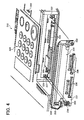
- FIG. 4 is an enlarged perspective view illustrating a portion of the operation panel shown in FIG. 3;
- FIG. 5 is a flowchart illustrating controlling a reading operation of the MFP shown in FIG. 1, according to an exemplary embodiment of the present invention;
- FIG. 6 is a perspective view illustrating the outer appearance of the MFP of FIG. 1 connected to a charging device, according to an exemplary embodiment of the present invention;
- FIG. 7 is a schematic block diagram illustrating the structure of the charging device shown in FIG. 6;
- FIGS. 8A to 8C are flowcharts illustrating controlling a reading operation of the MFP of FIG. 6, according to an exemplary embodiment of the present invention;
- FIG. 9 is an illustration of a screen displayed by the MFP shown in FIG. 6;
- FIG. 10 is an illustration of a screen displayed by the MFP shown in FIG. 6;
- FIG. 11 is an illustration of a screen displayed by the MFP shown in FIG. 6;
- FIG. 12 is an illustration of a screen displayed by the MFP shown in FIG. 6;
- FIG. 13 is an illustration of a screen displayed by the MFP shown in FIG. 6;
- FIGS. 14A to 14D are flowcharts illustrating controlling a reading operation of the MFP shown in FIG. 6, according to an exemplary embodiment of the present invention; and
- FIG. 15 is an illustration of a screen displayed by the MFP shown in FIG. 6.
- In describing the preferred embodiments illustrated in the drawings, specific terminology is employed for clarity. However, the disclosure of this patent specification is not intended to be limited to the specific terminology selected and it is to be understood that each specific element includes all technical equivalents that operate in a similar manner. Referring now to the drawings, wherein like reference numerals designate identical or corresponding parts throughout the several views, FIG. 1 illustrates an
MFP 500 according to an exemplary embodiment of the present invention. - The MFP 500 may look like a copier having a
reader 105 at the top surface, aprinter 103 in its inside, and anoperation panel 212. Theoperation panel 212 includes amedium interface 225, which includes one or more inlets each corresponding to a specific type of a portable medium. With this configuration, the MFP 500 reads data from at least one portable medium inserted in themedium interface 225, and performs various processing on the data including printing, faxing, copying, editing, etc. - Referring to FIG. 2, the MFP 500 mainly includes an
image processing unit 100 and anoperation control unit 200, which are connected to each other via ahub 2. However, theimage processing unit 100 and theoperation control unit 200 may be connected via any other communication device, such as a switch or a switching hub, for example. - The
hub 2 is further connected to a network NW, such as a local area network (LAN) or the Internet, for example, to create an image processing system with other apparatuses on the network NW. If thehub 2 is connected to the Internet via the LAN, thehub 2 may be provided with a communication controller, such as a router, exchanging device, cable modem, DSL modem, etc. - The
image processing unit 100 includes animage processing controller 101, aprinter controller 102, theprinter 103, areader controller 104, thereader 105, a hard disk drive (HDD) 106, afax controller 107, aLAN controller 108, aninput controller 109, adisplay controller 110, and a control panel interface (I/F) 111. - The
operation control unit 200 includes a central processing unit (CPU) 201, aLAN controller 202, amemory 203, astorage controller 204, astorage 205, adisplay controller 207, aninput controller 208, anaudio controller 209, an input/output (I/O)port controller 210, a control panel I/F 211, theoperation panel 212, an I/O device controller 213, amedium controller 214, and aninterface 215. In this example, theoperation panel 212 includes anoperation panel communicator 206, adisplay 221, aspeaker 222, abuzzer 223, aninput device 224, a medium I/F 225, and acover state detector 226. However, the structure of theoperation panel 212 is not limited to the structure shown in FIG. 2, as long as it includes a device capable of notifying a user of an instruction received from theCPU 201, such as a display, audio device including a buzzer or speaker, etc. - Referring to the
image processing unit 100, theimage processing controller 101 includes any kind of device capable of controlling image processing performed by theimage processing unit 100, such as a microcomputer. Theimage processing controller 101 includes aCPU 121, a read only memory (ROM) 122, a synchronous dynamic random access memory (SDRAM) 123, and a nonvolatile random access memory (NVRAM) 124, which are connected via a bus. TheCPU 121 operates as a main processor. TheROM 122 stores various programs such as a control program or system data to be used by theCPU 121 for controlling operation of theimage processing unit 100. The SDRAM 123 functions as a work memory area for theCPU 121. The NVRAM 124 stores various data, such as job history data or preference data, for example. - The HDD 106, which is connected to the
image processing controller 101, includes any kind of storage device capable of storing a large amount of data, including image data read by thereader 105, image data received by theLAN controller 108 or thefax controller 107, or image data processed by theimage processing controller 101. - In an example operation, the
CPU 121 loads a particular program from theROM 122, and applies image processing to image data according to the loaded program. The program may be previously stored in the HDD 106 or it may be downloaded from the network NW. Alternatively, the program may be installed from a storage medium such as an optical disc. - The
printer 103 includes any kind of device capable of forming an image on a recording medium. For example, theprinter 103 may form a toner image, using a predetermined image forming method including electrophotography, ink-jet, dye sublimation transfer, silver salt photography, thermal recording, thermal transfer, etc. - The
printer controller 102 includes any kind of device capable of controlling operation of theprinter 103, according to an instruction received from theimage processing controller 101. For example, upon receiving an instruction for printing image data processed by theimage processing controller 101, theprinter controller 102 causes theprinter 103 to print out the processed image data. - The
reader 105 includes any kind of device capable of reading an original image into image data. For example, thereader 105 may be implemented by a scanner, which irradiates light onto the original image, and converts the reflected light to an electric signal using a photoelectric conversion element. - The
reader controller 104 includes any kind of device capable of controlling operation of thereader 105, according to an instruction received from theimage processing controller 101. For example, upon receiving an instruction for reading from theimage processing controller 101, thereader controller 104 causes thereader 105 to read an original image into image data, i.e., an electric signal. Thereader controller 104 then converts the electric signal from analog to digital, and outputs the converted signal to theimage processing controller 101. - The
fax controller 107, which is connected to theimage processing controller 101, allows theimage processing unit 100 to communicate with other apparatuses via a public switch box (PBX) 300 and a public switched telephone network (PSTN). For example, thefax controller 107 can send or receive fax data to or from other apparatuses on the PSTN. - The
LAN controller 108, which is connected to theimage processing controller 101, is further connected to theoperation control unit 200 and to the network NW via thehub 2. Under control of theCPU 121, theLAN controller 108 may send or receive image data to or from theoperation control unit 200 or other apparatuses on the network NW. - The
input controller 109 controls exchange of a control signal between theimage processing controller 101 and theoperation control unit 200 via the control panel I/F 111. - The
display controller 110 controls output of a display control signal from theimage processing controller 101 to theoperation control unit 200 via the control panel I/F 111. - Referring to the
operation control unit 200, theLAN controller 202 is connected to thehub 2, and further to theLAN controller 108 of theimage processing unit 100 and to the network NW. Under control of theCPU 201, theLAN controller 202 may send or receive image data to or from theimage processing unit 100 or other apparatuses on the network NW. - The
CPU 201 includes any kind of processor capable of controlling operation of theoperation control unit 200. Thememory 203 includes any kind of memory device, such as a RAM functioning as a work memory for theCPU 201, and a ROM storing various data. - The
storage 205 stores various system data, including an operating system (OS) or various application programs, for example. Thestorage 205 may additionally store various data used for image processing, such as printing forms, for example. Thestorage controller 204 controls data input or data output of thestorage 205. - In an example operation, the
CPU 201 loads a particular program from thestorage 205. Using thememory 203 as a working area, theCPU 201 controls operation of theoperation control unit 200 according to the loaded program. - The
display controller 207 controls operation of thedisplay 221 through the control panel I/F 211. Theinput controller 208 detects whether any instruction from a user is input using theinput device 224, through the control panel I/F 211. Theaudio controller 209 controls operation of thespeaker 222 or operation of thebuzzer 223, under control of theCPU 201 through the control panel I/F 211. The I/O port controller 210 controls input or output of data to or from theoperation panel 212, under control of theCPU 201 through the control panel I/F 211. - The I/
O device controller 213 includes any kind of device capable of controlling operation of an input or output device connected through theinterface 215, such as an ear phone, a digital camera, etc. Theinterface 215 includes any kind of interface, such as USB, IEEE1394, or SCSI. Themedium controller 214 includes any kind of device capable of controlling operation of a storage medium drive, such as an optical disc drive, for example. - The
operation panel communicator 206 controls input or output of data to or from theoperation panel 212. Thedisplay 221 includes any kind of device capable of displaying data to a user, such as a liquid crystal display (LCD). Thespeaker 222 includes any kind of device capable of outputting a sound such as a voice message. Thebuzzer 223 includes any kind of device capable of outputting a sound such as a beep sound. - The
input device 224 allows a user to input an instruction. It may be provided with a plurality of keys or buttons, such as a ten key, a functional key, a keyboard, a touch panel, etc. - The medium I/
F 225 is where a portable medium is inserted. In this example, the medium I/F 225 is covered with a medium cover at least when the portable medium is inserted. - The
cover state detector 226 detects the state of the medium cover and sends the detection result to the I/O port controller 210 through the control panel I/F 211. Based on the detection result, theCPU 201 controls operation of theoperation control unit 200. - In this example, the portable medium includes any kind of portable medium capable of storing data using various means including light, magnetism, or electricity. Examples of portable medium include, but not limited to, optical discs such as CD-ROM, CD-R, CD-RW, DVD-ROM, DVD-RAM, DVD-R, DVD+R, DVD-RW, and DVD+RW, magneto optical (MO) discs, mini discs (MD), compact flash memory, memory stick, smart media, memory cards, Zip, floppy disk, digital audio tape (DAT), digital compact cassette (DCC), magnetic cards, multimedia cards, secure digital cards, and IC cards.
- Referring now to FIGS. 3 and 4, the structure of the
operation panel 212 is explained according to an exemplary embodiment of the present invention. - As shown in FIG. 3, the
display 221 is provided at a central portion of theoperation panel 221. At right and left sides of thedisplay 221, a plurality of keys is provided, which functions as theinput device 224. Two speakers, i.e., thespeaker 222, are provided at the side edges of theoperation panel 212. Thebuzzer 223 is provided inside theoperation panel 221. Themedium cover 230 is provided at the front side surface of theoperation panel 212 to cover the medium I/F 225 (FIG. 4). - In this example, as shown in FIG. 4, the medium I/
F 225 includes four inlets, each corresponding to a specific type of portable medium. However, the number or shapes of the inlets are not limited to this example. - The
medium cover 230 includes apanel section 231 and acover section 232. Fouropenings 236 are formed on thepanel section 231, each corresponding to the inlets of the medium I/F 225. Thepanel section 231 is fixed to the front side surface of theoperation panel 212 to cover themedium interface 225. For example, as illustrated in FIG. 4, a pair ofscrews 233 of thepanel section 231 may be screwed into a pair ofscrew receivers 237 to tightly fix thepanel section 231 onto the front side surface of theoperation panel 212. - The
cover section 232 is attached to thepanel section 231 such that it can move in the direction toward thepanel section 231 or in the direction away from thepanel section 231. Thecover section 232 may be formed in various shapes as long as it can cover theopenings 236 of thepanel section 231. - As illustrated in FIG. 4, the
cover state detector 226 is provided on the front side surface of theoperation panel 212, at the position right above one of thescrew receivers 237. In this example, thecover state detector 226 may be implemented by a switch, which is turned on when it is pressed. Further, apin 234 is provided on thepanel section 231 at the position corresponding to the position of thecover state detector 226. Aprotrude 235 is provided on thecover section 232 at the position corresponding to the position of thepin 234. With this structure, thecover state detector 226 can detect opening or closing of themedium cover 230. - For example, when the
medium cover 230 is closed, i.e., when thecover section 232 is in close contact with thepanel section 231, thepin 234 is pushed by theprotrude 235 toward thecover state detector 226. As a result, thecover state detector 226 is turned on to send an on signal to the I/O port controller 210 of FIG. 2. Based on the on signal, theCPU 201 can determine that themedium cover 230 is closed. - When the
medium cover 230 is open, i.e., when thecover section 232 is moved away from thepanel section 231 as illustrated in FIG. 4, theprotrude 235 is moved away from thepin 234, causing thepin 234 to move away from thecover state detector 226. As a result, thecover state detector 226 is turned off to send an off signal to the I/O port controller 210 of FIG. 2. Based on the off signal, theCPU 201 can determine that themedium cover 230 is open. In this example, thepin 234 is provided with an elastic member, such as a spring, which helps thepin 234 to return to the position away from thecover state detector 226. - Referring to FIG. 5, controlling a reading operation of the
MFP 500 according to opening or closing of themedium cover 230 is explained according to an exemplary embodiment of the present invention. The steps illustrated in FIG. 5 are performed by theCPU 201 according to an instruction received from a user through theinput device 224. - Step S1 selects image processing to be performed by the
MFP 500. For example, theMFP 500 may display a screen on thedisplay 221, which requests the user to select image processing to be performed by theMFP 500, such as printing or faxing, for example. In this step, the user is assumed to have selected image processing, which requires a reading operation for reading data from a portable medium. - Step S3 requests the user to insert the portable medium into the medium I/
F 225. For example, theCPU 201 may display a screen on thedisplay 221, asking the user to insert the portable medium. Alternatively, theCPU 201 may cause thebuzzer 223 to output a beep sound asking the user to insert the portable medium. Alternatively, theCPU 201 may cause the speaker to output a voice message asking the user to insert the portable medium. - Once the portable medium is inserted into the medium I/F 255, Step S5 starts an operation of reading data from the portable medium.
- While the reading operation is being performed, Step S7 determines whether the
medium cover 230 is closed using thecover state detector 226. If themedium cover 230 is closed ("YES" in Step S7), the operation proceeds to Step S9. If themedium cover 230 is open ("NO" in Step S7), the operation proceeds to Step S13. - Step S13 notifies the user that the
medium cover 230 is open. In this step, theCPU 201 may request the user to close themedium cover 230. For example, theCPU 201 may display a screen on thedisplay 221. Alternatively, theCPU 201 may cause thebuzzer 223 to output a beep sound. Alternatively, theCPU 201 may cause the speaker to output a voice message. - Step S15 determines whether the portable medium is removed out from the medium I/
F 225. If the portable medium is removed ("YES" in Step S15), the operation ends without completing the reading operation started in Step S5. If the portable medium is not removed ("NO" in Step S15), the operation returns to Step S7. - Step S9 determines whether the reading operation started in Step S5 has been completed. If the reading operation has been completed ("YES" in Step S9), the operation proceeds to Step S11. Otherwise ("NO" in Step S9), the operation returns to Step S7.
- Step S11 applies image processing selected in Step S1 to the data read out from the portable medium, and the operation ends.
- The operation of FIG. 5 may be performed in various ways. In one example, Step S7 may determine whether the
medium cover 230 has been kept closed. If themedium cover 230 was opened even at once during the reading operation started in Step S5 ("NO" in Step S7), the operation proceeds to Step S13. For example, a detection flag is initially set to 0, indicating that themedium cover 230 is closed. When themedium cover 230 is opened, the detection flag is changed to 1, indicating that themedium cover 230 is opened. Based on the value of the detection flag, theCPU 201 can determine whether themedium cover 230 has been kept closed during the reading operation. - In another example, in Step S15, if the portable medium has not been moved ("NO" in Step S15), the operation may return to Step S5 to restart the reading operation.
- In another example, in Step S15, if the portable medium has been removed ("YES" in Step S15), the operation may return to Step S1 to restart the operation from Step S1.
- In another example, if the reading operation has been completed ("YES" in Step S9), the
CPU 201 may further request the user to remove the portable medium from the medium I/F 255. For example, theCPU 201 may display a screen on thedisplay 221. Alternatively, theCPU 201 may cause thebuzzer 223 to output a beep sound. Alternatively, theCPU 201 may cause the speaker to output a voice message. - As descried above referring to FIG. 2, the
MFP 500 of FIG. 1 may be connected to other devices via the network NW or via theinterface 215. For example, theMFP 500 of FIG. 1 may be further connected to a charging device, such as acoin vendor 60 shown in FIG. 6, via theinterface 215. - As shown in FIG. 7, the
coin vendor 60 includes acoin input inlet 61, areturn button 62, acontrol circuit 63, acoin return inlet 64, acoin counter 65, amemory 66, aport 67, and a coin vendor I/F 68. Thecoin input inlet 61 inputs a coin received from a user. Thecontrol circuit 63 controls the entire operation of thecoin vendor 60. Thecoin return inlet 64 outputs a coin, for example, when thereturn button 62 is pressed by the user. Thecoin counter 65 counts the number of coins input through thecoin input inlet 61 to generate a counted result. Thememory 66 stores the counted result. Theport 67 allows thecoin vendor 60 to communicate with theMFP 500 via the coin vendor I/F 68. In addition to thecoin vendor 60 described referring to FIG. 7, any kind of charging device may be connected to theMFP 500. - Referring now to FIGS. 8A to 8C, controlling a reading operation of the
MFP 500 according to opening or closing of themedium cover 230 is explained according to an exemplary embodiment of the present invention. The steps illustrated in FIGS. 8A to 8C are performed by theCPU 201 according to an instruction from a user. - Referring to FIG. 8A, Step S101 displays an initial screen on the
display 221, which requests the user to select image processing to be performed by theMFP 500, such as a top menu M0 shown in FIG. 9. - Step S102 selects image processing to be performed. In this example, the user selects the "print" button of the top menu M0 to perform printing.
- Step S103 selects data to be processed. In this example, the user instructs the
MFP 500 to print data stored in a portable medium. - Step S104 displays a medium request screen, which requests the user to insert the portable medium, such as a medium request menu M1 shown in FIG. 10, for example. The medium request menu M1 includes a picture and a message. The picture of the medium request menu M1 may be a still image or a moving image. Further, in this step, the
buzzer 223 may output a beep sound to alarm the user. Furthermore, thespeaker 222 may output a voice message requesting for the portable medium. At this time, the user opens themedium cover 230, and inserts the portable medium into the medium I/F 225. After the portable medium has been inserted, themedium cover 230 is closed automatically or manually. - Step S106 determines whether the portable medium is readable by the
MFP 500. If the portable medium is readable ("YES" in Step S106), the operation proceeds to Step S108. If the portable medium is not readable ("NO" in Step S106), the operation returns to Step S101 to repeat Steps S101 to S106. In this step, a time period for determining whether the portable medium is readable may be previously set. When the previously-set time period has passed, the operation may automatically return to Step S101. - Alternatively, when the portable medium is not readable ("NO" in Step S106), the
CPU 201 may display an error message on thedisplay 221 indicating that the portable medium is not readable, and ends the operation. - Once the portable medium is recognized, Step S108 starts an operation of setting printing preferences, such as a printing type, printing form type, document type, printing sheet size, etc. For example, the user may input the printing preferences using the
input device 224. The printing preferences are then sent to theinput controller 208 through the control panel I/F 211 as described referring to FIG. 2. - While the printing preferences are being set, Step S109 determines whether the
medium cover 230 is closed. As described referring to FIG. 2, thecover state detector 226 detects whether themedium cover 230 is closed, and sends the detection result to the I/O port controller 210 through the control panel I/F 211. Based on the detection result, whether to continue or interrupt the setting operation is determined. If themedium cover 230 is closed ("YES" in Step S109), the operation proceeds to Step S113. If themedium cover 230 is open ("NO" in Step S109), the operation proceeds to Step S110. - Step S110 displays an alarm screen on the
display 221, which requests the user to close themedium cover 230, such as an alarm menu M2 shown in FIG. 11, for example. The alarm menu M2 includes the message and theOK button 250. Further, in this step, thebuzzer 233 may output a beep sound to alarm the user. Furthermore, thespeaker 222 may output a voice message requesting the user to close themedium cover 230. - If the alarm menu M2 is displayed, Step S110 may further wait until the user selects the "OK"
button 250 of the alarm menu M2. Once the "OK"button 250 is selected such as by using theinput device 224, the operation proceeds to Step S111. Alternatively, a time period for displaying the alarm menu M2 in Step S110 may be previously set. If the previously-set time period has passed, the operation automatically proceeds to Step S111 regardless of whether the "OK"button 250 is selected. - Step S111 determines whether the portable medium is removed out from the medium I/
F 225. If the portable medium stays in the medium I/F 225 ("NO" in Step S111), the operation returns to Step S109. If the portable medium is removed from the medium I/F 225 ("YES" in Step S111), the operation proceeds to Step S112 (FIG. 8C) to display a cancel screen, which requests the user to cancel the printing job, such as a cancel menu M3 shown in FIG. 12, for example. The cancel menu M3 includes the message and theOK button 250. Further, in this step, thebuzzer 233 may output a beep sound to alarm the user. Furthermore, thespeaker 222 may output a voice message requesting the user to cancel the printing job. - If the cancel menu M3 is displayed, Step S112 may further wait until the user selects the "OK"
button 250 of the cancel menu M3. Once the "OK"button 250 is selected such as by using theinput device 224, the operation ends without performing the printing job. Alternatively, a time period for displaying the cancel menu M3 in Step S112 may be previously set. If the previously-set time period has passed, the operation automatically ends regardless of whether the "OK"button 250 is selected. Alternatively, the operation may return to Step S101 to start over the entire process. - In Step S109 of FIG. 8A, if the
medium cover 230 is closed ("YES" in Step S109), the operation proceeds to Step S113 to determine whether the setting operation started in Step S108 has been completed. If the setting operation is completed ("YES" in Step S113), the operation proceeds to Step S114 (FIG. 8B) to start an operation of reading data from the portable medium. If the setting operation is not completed ("NO" in Step S113), the operation returns to Step S109 to continue the setting operation. - Referring to FIG. 8B, while the data is being read in Step S114, Step S115 determines whether the
medium cover 230 is closed in a substantially similar manner as described referring to Step S109. If themedium cover 230 is closed ("YES" in Step S115), the operation proceeds to Step S119. If themedium cover 230 is open ("NO" in Step S115), the operation proceeds to Step S116. - Step S116 interrupts the reading operation started in Step S114.
- Step S117 displays an alarm screen on the
display 221, which requests the user to close themedium cover 230, such as the alarm menu M2 shown in FIG. 11, for example. Further, in this step, a sound, such as a beep sound or a voice message, may be output. If the alarm menu M2 is displayed, Step S117 may further wait until the user selects the "OK"button 250 of the menu M2. Once the "OK"button 250 is selected such as by using theinput device 224, the operation proceeds to Step S118. Alternatively, a time period for displaying the alarm menu M2 in Step S117 may be previously set. If the previously-set time period has passed, the operation automatically proceeds to Step S118 regardless of whether the "OK"button 250 is selected. - Step S118 determines whether the portable medium is removed out from the medium I/
F 225. If the portable medium stays in the medium I/F 225 ("NO" in Step S118), the operation returns to Step S114 to resume the reading operation. If the portable medium is removed from the medium I/F 225 ("YES" in Step S118), the operation proceeds to Step S112 (FIG. 8C) to display a cancel screen, such as the cancel menu M3 of FIG. 12. After the cancel screen is displayed, the operation may end or may return to Step S101. - In Step S115 of FIG. 8B, when the medium cover is closed ("YES" in Step S115), the operation proceeds to Step S119 to complete the reading operation. Step S119 further selects data from the data read out from the portable medium in Step S114. For example, the
CPU 201 may generate a thumbnail image for each of data files stored in the portable medium, and displays the thumbnail images on thedisplay 221. TheCPU 201 then allows the user to select one of the thumbnail images using theinput device 224. - While the selection is being made, Step S120 determines whether the
medium cover 230 is closed. If themedium cover 230 is closed ("YES" in Step S120), the operation proceeds to Step S121. If themedium cover 230 is open ("NO" in Step S120), the operation proceeds to Step S122. - Step S122 displays an alarm screen on the
display 221, which requests the user to close themedium cover 230, such as the alarm menu M2 of FIG. 11. Further, in this step, a sound, such as a beep sound or a voice message, may be output. If the alarm menu M2 is displayed, Step S122 may further wait until the user selects the "OK"button 250 of the alarm menu M2. Once the "OK"button 250 is selected such as by using theinput device 224, the operation proceeds to Step S123. Alternatively, a time period for displaying the alarm menu M2 in Step S122 may be previously set. If the previously-set time period has passed, the operation automatically proceeds to Step S123 regardless of whether the "OK"button 250 is selected. - Step S123 determines whether the portable medium is removed out from the medium I/
F 225. If the portable medium stays in the medium I/F 225 ("NO" in Step S123), the operation returns to Step S120. If the portable medium is removed from the medium I/F 225 ("YES" in Step S123), the operation proceeds to Step S112 to display a cancel screen, such as the cancel menu M3 of FIG. 12. After the cancel screen is displayed, the operation may end or may return to Step S101. - In Step S120, if the
medium cover 230 is closed ("YES" in Step S120), it is determined whether the data selection started in Step S119 has been completed. If the selection is completed ("YES" in Step S121), the operation proceeds to Step S124 to start printing preparation. If the selection is not completed ("NO" in Step S121), the operation returns to Step S120 to continue the selecting operation. The printing preparation includes Step S125 (FIG. 8C) of reading the data selected in Step S119 from the portable medium. In addition, the printing preparation includes the step of converting the selected data according to the printing preferences input in Step S108. - Referring to FIG. 8C, while the printing preparation is being made in Steps S124 (FIG. 8B) and S125, Step S126 determines whether the
medium cover 230 is closed in a substantially similar manner as described referring to Step S109. If themedium cover 230 is closed ("YES" in Step S126), the operation proceeds to Step S127. If themedium cover 230 is open ("NO" in Step S126), the operation proceeds to Step S128. - Step S128 interrupts the reading operation performed in Step S125.
- Step S129 displays an alarm screen on the
display 221, such as the alarm menu M2 of FIG. 11. Further, in this step, a sound, such as a beep sound or a voice message, may be output. If the alarm menu M2 is displayed, Step S129 may further wait until the user selects the "OK"button 250 of the alarm menu M2. Once the "OK"button 250 is selected such as by using theinput device 224, the operation proceeds to Step S130. Alternatively, a time period for displaying the alarm menu M2 in Step S129 may be previously set. If the previously-set time period has passed, the operation automatically proceeds to Step S130 regardless of whether the "OK"button 250 is selected. - Step S130 determines whether the portable medium is removed out from the medium I/
F 225. If the portable medium stays in the medium I/F 225 ("NO" in Step S130), the operation returns to Step S125. If the portable medium is removed from the medium I/F 225 ("YES" in Step S130), the operation proceeds to Step S112 to display a cancel screen, such as the cancel menu M3 of FIG. 12. After the cancel screen is displayed, the operation may end or it may return to Step S101. - In Step S126, if the
medium cover 230 is closed ("YES" in Step S126), Step S127 determines whether the printing preparation started in Step S124 has been completed. If the printing preparation has been completed ("YES" in Step S127), the operation proceeds to Step S131. If the printing preparation has not been completed ("NO" in Step S127), the operation continues the printing preparation started in Step S124, such as Step S125 of reading the selected data. - Once the printing preparation has been completed, Step S131 displays a removal request screen, which requests the user to remove the portable medium from the medium I/F 255. At this time, the user opens the
medium cover 230, and removes the portable medium from the medium I/F 255. Further, in this step, a sound, such as a beep sound or a voice message, may be output. This may prevent the user from accidentally leaving the portable medium in the medium I/F 255. - Step S132 calculates a charged amount, and displays a charge screen on the
display 221, which requests the user to pay the charged amount. At this time, the user pays the charged amount using thecoin vendor 60. However, the user may pay the charged amount using a card, for example, such as a pre-paid card. - Step S133 prints the selected data according to the printing preferences. For example, the data prepared for printing is sent to the
image processing unit 100 via the hub 2 (FIG. 2). Once the prepared data has been recognized by theCPU 121, theCPU 121 instructs theprinter controller 102 to print the prepared data using theprinter 103. - Step S135 displays a complete screen on the
display 221, which notifies the user that the printing job has been completed, such as a complete menu M4 shown in FIG. 13, for example. The complete menu M4 includes the message and the "OK"button 250. Further, in this step, a sound, such as a beep sound or a voice message, may be output. Once the "OK"button 250 is selected such as by using theinput device 224, the operation ends. Alternatively, a time period for displaying the complete menu M4 in Step S135 may be previously set. If the previously-set time period has passed, the operation automatically ends regardless of whether the "OK"button 250 is selected. Once the operation is completed, theCPU 201 may cause thedisplay 221 to display an initial screen, such as the top menu M0 of FIG. 9. - In this manner as described referring to FIGS. 8A to 8C, even when the portable medium is accidentally removed while performing a reading operation, the portable medium can be protected from being damaged. Further, the reading operation may be carried out more smoothly without stalling, or it may be completed more successfully without failure.
- Referring now to FIGS. 14A to 14D, controlling a reading operation of the
MFP 500 according to opening or closing of themedium cover 230 is explained according to an exemplary embodiment of the present invention. The operation illustrated in FIGS. 14A to 14D is substantially similar to the operation illustrated in FIGS. 8A to 8C. The differences include the addition of Steps S232 (FIG. 14C), S233 (FIG. 14C), S234 (FIG. 14C), S235 (FIG. 14C), and S229 (FIG. 14D). - Referring to FIG. 14C, while the printing preparation is performed, including Step S125 of reading the selected data, Step S126 determines whether the
medium cover 230 is closed. If themedium cover 230 is open ("NO" in Step S126), the operation proceeds to Step S128 (FIG. 14D) to interrupt the reading operation performed in Step S125. - Referring to FIG. 14D, Step S229 sets a detection flag to 1, indicating that the
medium cover 230 is open. - Step S129 displays an alarm screen on the
display 221, such as the alarm menu M2 of FIG. 11, for example. Further, in this step, a sound, such as a beep sound or a voice message, may be output. If the alarm menu M2 is displayed, Step S129 may further wait until the user selects the "OK"button 250 of the alarm menu M2. Once the "OK"button 250 is selected such as by using theinput device 224, the operation proceeds to Step S130. Alternatively, a time period for displaying the alarm menu M2 in Step S129 may be previously set. If the previously-set time period has passed, the operation automatically proceeds to Step S130 regardless of whether the "OK"button 250 is selected. - Referring back to FIG. 14C, if Step S126 determines that the
medium cover 230 is closed ("YES" in Step S126), the operation proceeds to Step S127 to determine whether the printing preparation performed in Steps S124 and S125 has been completed. If the printing preparation has been completed ("YES" in Step S127), the operation proceeds to Step S232. Otherwise ("NO" in Step S127), the operation returns to Step S125 to continue the printing preparation, i.e., the reading operation. - Step S232 determines whether the detection flag is set to 0. If the detection flag is set to 0 ("YES" in Step S232) indicating that the
medium cover 230 has been kept closed while performing the printing preparation, the operation proceeds to Step S235. If the detection flag is set to 1 ("NO" in Step S232) indicating that themedium cover 230 was opened even at once while performing the printing preparation, the operation proceeds to Step S233. - Step S235 resets the detection flag to 0, and the operation proceeds to Step S131 to display a removal request screen. However, once it is determined that the detection flag is set to 0 in Step S232, the operation may proceed to Step S131 without performing Step S235 of setting the detection flag to 0.
- Step S233 displays a re-read screen on the
display 221, which gives the user an option of re-reading the data from the portable medium, such as a re-read menu M5 shown in FIG. 15. The re-read menu M5 requests the user to select either the "Read again"button 251 or the "Continue"button 252. Further, in this step, a sound, such as a beep sound or a voice message, may be output. - Step S234 determines whether the "Read again" button is selected from the re-read menu M5. If the "Read again" button is selected ("YES" in Step S234), the operation returns to Step S125 to start again the reading operation. If the "Continue" button is selected ("NO" in Step S234), the operation proceeds to Step S235 without performing the reading operation again.
- The operation of FIG. 14 may be performed in different ways. For example, when the detection flag is set to 0 ("YES" in Step S232), the operation may proceed to Step S131 without performing the Step S235.
- In this manner as described referring to FIGS. 14A to 14D, even when the portable medium is accidentally removed while performing a reading operation, the portable medium can be protected from being damaged. Further, the reading operation may be carried out more smoothly without stalling, or it may be completed more successfully without failure. Furthermore, the user may easily request the
MFP 500 to perform the reading operation again in case the portable medium is removed. - Numerous additional modifications and variations are possible in light of the above teachings. It is therefore to be understood that within the scope of the appended claims, the disclosure of this patent specification may be practiced in ways other than those specifically described herein.
- For example, elements and/or features of different illustrative embodiments may be combined with each other and/or substituted for each other within the scope of this disclosure and appended claims.
- Further, any one of the above-described and other methods or functions of the present invention may be performed by an image processing apparatus other than the
MFP 500. - Furthermore, as described above, any one of the above-described and other methods of the present invention may be embodied in the form of a computer program stored in any kind of storage medium. Examples of storage mediums include, but are not limited to, flexible disk, hard disk, optical discs, magneto-optical discs, magnetic tapes, involatile memory cards, ROM (read-only-memory), etc.
- Alternatively, any one of the above-described and other methods of the present invention may be implemented by ASIC, prepared by interconnecting an appropriate network of conventional component circuits or by a combination thereof with one or more conventional general purpose microprocessors and/or signal processors programmed accordingly.
- This patent application is based on and claims priority to Japanese patent application No. 2004-320098 filed on November 4, 2004, in the Japanese Patent Office, the entire contents of which are hereby incorporated by reference.
Claims (18)
- An image processing apparatus having an operation panel, comprising:a medium interface formed on a first surface of the operation panel for inserting therein a portable medium storing data;a medium cover having a panel section tightly fixed to the first surface of the operation panel and a cover section movably attached to the panel section, the cover section being configured to close for covering the medium interface and to open for exposing the medium interface;a detector provided on the first surface of the operation panel for generating a detection result indicating a state of the medium cover; anda processor coupled to the operation panel for controlling a reading operation for reading the data from the portable medium, wherein the reading operation is controlled based on the detection result.
- The apparatus of claim 1, wherein the detection result comprises:a first state indicating that the medium cover is kept closed during the reading operation; anda second state indicating that the medium cover is opened once or more than once during the reading operation.
- The apparatus of claim 1 or 2, further comprising:a display provided on a second surface of the operation panel for displaying a screen selected by the processor based on the detection result.
- The apparatus of any one of claims 1 to 3, further comprising:an audio device for outputting a sound selected by the processor based on the detection result.
- The apparatus of any one of claims 1 to 4, further comprising:an input device provided on the second surface of the operation panel for inputting an instruction from a user.
- The apparatus of any one of claims 1 to 5, further comprising:an image forming device coupled to the processor for outputting the data read from the portable medium under control of the processor.
- An image processing apparatus, comprising:a medium interface to which a portable medium storing data is inserted;a medium cover configured to be closed to cover the medium interface and to be opened to expose the medium interface;a detector configured to detect opening or closing of the medium cover to generate a detection result;a controller configured to activate a reading operation for reading the data from the portable medium; anda storage device storing a plurality of instructions, configured to cause the controller to perform a control operation comprising the steps of:activating a reading operation for reading the data from the portable medium;determining whether to interrupt the reading operation based on the detection result.
- The apparatus of claim 7, further comprising:a notifying device configured to notify a user of an instruction generated by the controller based on the detection result.
- The apparatus of claim 8, wherein the control operation further comprises the steps of:interrupting the reading operation when the detection result indicates that the medium cover is opened; andrequesting the user to close the medium cover through the notifying device.
- The apparatus of claim 9, wherein the control operation further comprises the step of:determining whether the portable medium is removed from the medium interface.
- The apparatus of claim 10, wherein the control operation further comprises the step of:canceling the reading operation when the determining step determines that the portable medium is removed.
- The apparatus of claim 10, wherein the control operation further comprises the step of:requesting the user to cancel the reading operation when the determining step determines that the portable medium is removed.
- The apparatus of claim 10, wherein the control operation further comprises the step of:requesting the user to repeat the reading operation when the determining step determines that the portable medium is inserted to generate a read request result; andrepeating the reading operation based on the read request result.
- The apparatus of claim 7, wherein the control operation further comprises the steps of:determining whether the reading operation is completed when the detection result indicates that the medium cover is closed to generate a complete result; andrequesting the user to remove the portable medium from the medium interface through the notifying device when the complete result indicates that the reading operation is completed.
- The apparatus of claim 14, wherein the control operation further comprises the step of:determining whether the portable medium is removed after the requesting step to generate a removal detection result; andrepeating the requesting step when the removal detection result indicates that the portable medium is inserted.
- The apparatus of claim 14, wherein the control operation further comprises the step of:applying image processing to the data read from the portable medium.
- An image processing apparatus, comprising:means for inserting therein a portable medium storing data;means for covering the inserting means in a first state;means for generating a detection result indicating whether the covering means is in the first state; andmeans for controlling a reading operation for reading the data from the portable medium based on the detection result.
- The apparatus of claim 17, further comprising:means for outputting notification generated by the controlling means based on the detection result.
Applications Claiming Priority (1)
| Application Number | Priority Date | Filing Date | Title |
|---|---|---|---|
| JP2004320098A JP4365305B2 (en) | 2004-11-04 | 2004-11-04 | Image processing device |
Publications (1)
| Publication Number | Publication Date |
|---|---|
| EP1657904A1 true EP1657904A1 (en) | 2006-05-17 |
Family
ID=35686531
Family Applications (1)
| Application Number | Title | Priority Date | Filing Date |
|---|---|---|---|
| EP05256836A Ceased EP1657904A1 (en) | 2004-11-04 | 2005-11-04 | Medium cover for controlling access to a portable medium inserted in an image processing apparatus |
Country Status (3)
| Country | Link |
|---|---|
| US (1) | US7551297B2 (en) |
| EP (1) | EP1657904A1 (en) |
| JP (1) | JP4365305B2 (en) |
Cited By (1)
| Publication number | Priority date | Publication date | Assignee | Title |
|---|---|---|---|---|
| EP1895757A1 (en) * | 2006-09-01 | 2008-03-05 | Ricoh Company, Ltd. | Image processing apparatus equipped with card reader setting table |
Families Citing this family (9)
| Publication number | Priority date | Publication date | Assignee | Title |
|---|---|---|---|---|
| US7855346B2 (en) | 2006-09-15 | 2010-12-21 | Ricoh Company, Ltd. | Data processing apparatus and removal recording media |
| JP2008105406A (en) | 2006-09-28 | 2008-05-08 | Brother Ind Ltd | Image formation apparatus |
| US20080158602A1 (en) * | 2006-12-28 | 2008-07-03 | Yasuhiro Nakai | Data processing apparatus |
| US8743367B2 (en) * | 2007-05-21 | 2014-06-03 | Bio-Rad Laboratories Inc. | Optical resonance analysis using a multi-angle source of illumination |
| JP2010042630A (en) * | 2008-08-18 | 2010-02-25 | Seiko Epson Corp | Printer, control method of printer, and printing system |
| DE102009038730B4 (en) | 2009-08-27 | 2014-03-13 | Vacuumschmelze Gmbh & Co. Kg | Laminated core made of soft magnetic single sheets, electromagnetic actuator and method for their production and use of a soft magnetic laminated core |
| JP5555041B2 (en) * | 2010-04-15 | 2014-07-23 | キヤノン株式会社 | Communication system, voice guidance output control method, transmission side device, reception side device, program, storage medium |
| JP6012977B2 (en) | 2012-02-15 | 2016-10-25 | シャープ株式会社 | Image forming apparatus |
| DE102015218421A1 (en) | 2015-09-24 | 2017-03-30 | Continental Automotive Gmbh | Magnetic armature for an electromagnetic actuator and injection valve for metering a fluid |
Citations (10)
| Publication number | Priority date | Publication date | Assignee | Title |
|---|---|---|---|---|
| US4897735A (en) * | 1987-10-28 | 1990-01-30 | Ricoh Company, Ltd. | Image processing apparatus for multi-media copying machine |
| JPH04205691A (en) * | 1990-11-30 | 1992-07-27 | Toshiba Corp | Portable electronic device |
| JPH05233475A (en) * | 1992-02-21 | 1993-09-10 | Sanyo Electric Co Ltd | Information processor |
| EP0563884A2 (en) * | 1992-03-31 | 1993-10-06 | Kabushiki Kaisha Toshiba | An image forming apparatus having a filing section and a printing section |
| EP0854630A2 (en) * | 1997-01-21 | 1998-07-22 | Xerox Corporation | An auto-function switching in a multi-functional machine |
| US20010017664A1 (en) * | 2000-02-28 | 2001-08-30 | Takeshi Misawa | Image-capturing apparatus |
| US20020033959A1 (en) * | 2000-08-02 | 2002-03-21 | Jitsuhiko Ando | Image printing system and image printing apparatus |
| US6491226B1 (en) * | 1998-08-24 | 2002-12-10 | Nec Infrontia Corporation | Method and apparatus for preventing extraction of card-shaped functional device for information processing apparatus, and recording medium storing program for realizing extraction preventing operation on computer |
| US6498658B1 (en) * | 1997-10-24 | 2002-12-24 | Minolta Co., Ltd. | Digital copying apparatus |
| US20040130732A1 (en) * | 2003-01-08 | 2004-07-08 | Brother Kogyo Kabushiki Kaisha | Media access lamp |
Family Cites Families (23)
| Publication number | Priority date | Publication date | Assignee | Title |
|---|---|---|---|---|
| JPS62170068A (en) * | 1986-01-22 | 1987-07-27 | Mitsubishi Electric Corp | Flexible disk drive device |
| JPH0252782A (en) * | 1988-08-17 | 1990-02-22 | Ricoh Co Ltd | Electronic apparatus |
| JP2838731B2 (en) * | 1990-09-27 | 1998-12-16 | 株式会社リコー | Openable cover |
| JPH04195597A (en) * | 1990-11-28 | 1992-07-15 | Toshiba Corp | Portable terminal equipment |
| JPH04305866A (en) * | 1991-04-02 | 1992-10-28 | Hitachi Ltd | Optical disk driver |
| JP3897368B2 (en) * | 1995-10-11 | 2007-03-22 | キヤノン株式会社 | Expansion card mounting device |
| JPH11134487A (en) * | 1997-10-27 | 1999-05-21 | Fuji Photo Film Co Ltd | Scanner and its operation control method |
| JP2001094698A (en) * | 1999-09-24 | 2001-04-06 | Canon Inc | Image reader |
| JP2001307029A (en) * | 2000-04-27 | 2001-11-02 | Olympus Optical Co Ltd | Electronic equipment |
| JP2002300334A (en) * | 2001-03-30 | 2002-10-11 | Dainippon Printing Co Ltd | Image printer |
| JP2002046324A (en) * | 2000-08-02 | 2002-02-12 | Dainippon Printing Co Ltd | Image printing service system |
| JP2002252821A (en) * | 2001-02-23 | 2002-09-06 | Dainippon Printing Co Ltd | Image printing system |
| JP2002292964A (en) * | 2001-04-03 | 2002-10-09 | Dainippon Printing Co Ltd | Image printer |
| JP2002236972A (en) * | 2001-02-13 | 2002-08-23 | Dainippon Printing Co Ltd | Information terminal table and information output system |
| JP2002281205A (en) * | 2001-03-21 | 2002-09-27 | Ricoh Co Ltd | Image forming device |
| JP2003244605A (en) * | 2002-02-14 | 2003-08-29 | Ricoh Co Ltd | Digital still camera |
| US7480439B2 (en) * | 2002-03-25 | 2009-01-20 | Panasonic Corporation | Recording device recording method and program |
| JP3674595B2 (en) * | 2002-03-29 | 2005-07-20 | ブラザー工業株式会社 | Document reader |
| JP2004048696A (en) * | 2002-05-08 | 2004-02-12 | Ricoh Co Ltd | Image forming apparatus and data processing method |
| JP2003331221A (en) * | 2002-05-17 | 2003-11-21 | Toshiba Corp | Ic card processing device |
| EP1482720A1 (en) * | 2003-05-28 | 2004-12-01 | Ricoh Company, Ltd. | Image processing apparatus and computer product |
| JP2005176043A (en) * | 2003-12-12 | 2005-06-30 | Canon Inc | Recording or reproducing device |
| US7855346B2 (en) * | 2006-09-15 | 2010-12-21 | Ricoh Company, Ltd. | Data processing apparatus and removal recording media |
-
2004
- 2004-11-04 JP JP2004320098A patent/JP4365305B2/en not_active Expired - Fee Related
-
2005
- 2005-11-04 EP EP05256836A patent/EP1657904A1/en not_active Ceased
- 2005-11-04 US US11/266,231 patent/US7551297B2/en not_active Expired - Fee Related
Patent Citations (10)
| Publication number | Priority date | Publication date | Assignee | Title |
|---|---|---|---|---|
| US4897735A (en) * | 1987-10-28 | 1990-01-30 | Ricoh Company, Ltd. | Image processing apparatus for multi-media copying machine |
| JPH04205691A (en) * | 1990-11-30 | 1992-07-27 | Toshiba Corp | Portable electronic device |
| JPH05233475A (en) * | 1992-02-21 | 1993-09-10 | Sanyo Electric Co Ltd | Information processor |
| EP0563884A2 (en) * | 1992-03-31 | 1993-10-06 | Kabushiki Kaisha Toshiba | An image forming apparatus having a filing section and a printing section |
| EP0854630A2 (en) * | 1997-01-21 | 1998-07-22 | Xerox Corporation | An auto-function switching in a multi-functional machine |
| US6498658B1 (en) * | 1997-10-24 | 2002-12-24 | Minolta Co., Ltd. | Digital copying apparatus |
| US6491226B1 (en) * | 1998-08-24 | 2002-12-10 | Nec Infrontia Corporation | Method and apparatus for preventing extraction of card-shaped functional device for information processing apparatus, and recording medium storing program for realizing extraction preventing operation on computer |
| US20010017664A1 (en) * | 2000-02-28 | 2001-08-30 | Takeshi Misawa | Image-capturing apparatus |
| US20020033959A1 (en) * | 2000-08-02 | 2002-03-21 | Jitsuhiko Ando | Image printing system and image printing apparatus |
| US20040130732A1 (en) * | 2003-01-08 | 2004-07-08 | Brother Kogyo Kabushiki Kaisha | Media access lamp |
Non-Patent Citations (2)
| Title |
|---|
| PATENT ABSTRACTS OF JAPAN vol. 016, no. 547 (P - 1452) 17 November 1992 (1992-11-17) * |
| PATENT ABSTRACTS OF JAPAN vol. 017, no. 692 (P - 1663) 17 December 1993 (1993-12-17) * |
Cited By (2)
| Publication number | Priority date | Publication date | Assignee | Title |
|---|---|---|---|---|
| EP1895757A1 (en) * | 2006-09-01 | 2008-03-05 | Ricoh Company, Ltd. | Image processing apparatus equipped with card reader setting table |
| US8004699B2 (en) | 2006-09-01 | 2011-08-23 | Ricoh Company, Ltd. | Image processing apparatus with card reader setting table |
Also Published As
| Publication number | Publication date |
|---|---|
| JP4365305B2 (en) | 2009-11-18 |
| US20060092434A1 (en) | 2006-05-04 |
| US7551297B2 (en) | 2009-06-23 |
| JP2006135462A (en) | 2006-05-25 |
Similar Documents
| Publication | Publication Date | Title |
|---|---|---|
| EP1657904A1 (en) | Medium cover for controlling access to a portable medium inserted in an image processing apparatus | |
| JP2004209853A (en) | Image forming apparatus | |
| JPH04270554A (en) | Picture recording device | |
| CN100472367C (en) | Image forming apparatus, display control method and display control program product | |
| US8909086B2 (en) | Image forming apparatus, image forming method, and storage medium | |
| US20110244441A1 (en) | Help display device, operation device and electronic apparatus | |
| JP7385713B2 (en) | Image forming apparatus and control method | |
| US7812989B2 (en) | System and method for voice help on a topic the user selects at the device, or to correct an error at a multi-function peripheral (MFP) | |
| US10509352B2 (en) | Image forming system, image forming apparatus, and recording medium configured to image belongings of a user and assist the user | |
| EP2202585B1 (en) | Copier | |
| CN101304463B (en) | Operation system of electronic device and image processing device | |
| JP2020065205A (en) | Image forming system | |
| JP3823521B2 (en) | Image forming apparatus | |
| JP4280484B2 (en) | Image forming apparatus and warning method used in the apparatus | |
| JP5842038B2 (en) | Image reading apparatus and image forming apparatus having the same | |
| JP7363088B2 (en) | Image forming device and method of controlling the image forming device | |
| JP5282652B2 (en) | Image processing apparatus, image processing method, and image processing program | |
| JP3600575B2 (en) | Image forming apparatus, image reading apparatus, and program | |
| JP6784268B2 (en) | Image forming device | |
| JP4368252B2 (en) | Image recording device | |
| JP2006229686A (en) | Image processor, image processing method and image processing program | |
| JP2007053806A (en) | Image forming apparatus and warning method for use in same | |
| JP2022067807A (en) | Image forming apparatus, automatic copying method, and automatic copying program | |
| JPH08339105A (en) | Image forming device | |
| JP2003174531A (en) | Device and system for forming image |
Legal Events
| Date | Code | Title | Description |
|---|---|---|---|
| PUAI | Public reference made under article 153(3) epc to a published international application that has entered the european phase |
Free format text: ORIGINAL CODE: 0009012 |
|
| 17P | Request for examination filed |
Effective date: 20051111 |
|
| AK | Designated contracting states |
Kind code of ref document: A1 Designated state(s): AT BE BG CH CY CZ DE DK EE ES FI FR GB GR HU IE IS IT LI LT LU LV MC NL PL PT RO SE SI SK TR |
|
| AX | Request for extension of the european patent |
Extension state: AL BA HR MK YU |
|
| 17Q | First examination report despatched |
Effective date: 20061221 |
|
| AKX | Designation fees paid |
Designated state(s): DE FR GB |
|
| STAA | Information on the status of an ep patent application or granted ep patent |
Free format text: STATUS: THE APPLICATION HAS BEEN REFUSED |
|
| 18R | Application refused |
Effective date: 20140426 |