EP1656883A1 - Portable device for measuring EMG signal - Google Patents
Portable device for measuring EMG signal Download PDFInfo
- Publication number
- EP1656883A1 EP1656883A1 EP04447248A EP04447248A EP1656883A1 EP 1656883 A1 EP1656883 A1 EP 1656883A1 EP 04447248 A EP04447248 A EP 04447248A EP 04447248 A EP04447248 A EP 04447248A EP 1656883 A1 EP1656883 A1 EP 1656883A1
- Authority
- EP
- European Patent Office
- Prior art keywords
- signal
- emg
- acquisition
- stimulation
- electrodes
- Prior art date
- Legal status (The legal status is an assumption and is not a legal conclusion. Google has not performed a legal analysis and makes no representation as to the accuracy of the status listed.)
- Withdrawn
Links
Images


Classifications
-
- A—HUMAN NECESSITIES
- A61—MEDICAL OR VETERINARY SCIENCE; HYGIENE
- A61B—DIAGNOSIS; SURGERY; IDENTIFICATION
- A61B5/00—Measuring for diagnostic purposes; Identification of persons
- A61B5/48—Other medical applications
- A61B5/4821—Determining level or depth of anaesthesia
-
- A—HUMAN NECESSITIES
- A61—MEDICAL OR VETERINARY SCIENCE; HYGIENE
- A61B—DIAGNOSIS; SURGERY; IDENTIFICATION
- A61B5/00—Measuring for diagnostic purposes; Identification of persons
- A61B5/24—Detecting, measuring or recording bioelectric or biomagnetic signals of the body or parts thereof
- A61B5/30—Input circuits therefor
-
- A—HUMAN NECESSITIES
- A61—MEDICAL OR VETERINARY SCIENCE; HYGIENE
- A61B—DIAGNOSIS; SURGERY; IDENTIFICATION
- A61B5/00—Measuring for diagnostic purposes; Identification of persons
- A61B5/24—Detecting, measuring or recording bioelectric or biomagnetic signals of the body or parts thereof
- A61B5/316—Modalities, i.e. specific diagnostic methods
- A61B5/389—Electromyography [EMG]
-
- A—HUMAN NECESSITIES
- A61—MEDICAL OR VETERINARY SCIENCE; HYGIENE
- A61B—DIAGNOSIS; SURGERY; IDENTIFICATION
- A61B5/00—Measuring for diagnostic purposes; Identification of persons
- A61B5/40—Detecting, measuring or recording for evaluating the nervous system
- A61B5/4029—Detecting, measuring or recording for evaluating the nervous system for evaluating the peripheral nervous systems
- A61B5/4041—Evaluating nerves condition
-
- A—HUMAN NECESSITIES
- A61—MEDICAL OR VETERINARY SCIENCE; HYGIENE
- A61B—DIAGNOSIS; SURGERY; IDENTIFICATION
- A61B5/00—Measuring for diagnostic purposes; Identification of persons
- A61B5/72—Signal processing specially adapted for physiological signals or for diagnostic purposes
- A61B5/7203—Signal processing specially adapted for physiological signals or for diagnostic purposes for noise prevention, reduction or removal
- A61B5/7217—Signal processing specially adapted for physiological signals or for diagnostic purposes for noise prevention, reduction or removal of noise originating from a therapeutic or surgical apparatus, e.g. from a pacemaker
-
- H—ELECTRICITY
- H03—ELECTRONIC CIRCUITRY
- H03M—CODING; DECODING; CODE CONVERSION IN GENERAL
- H03M1/00—Analogue/digital conversion; Digital/analogue conversion
- H03M1/12—Analogue/digital converters
- H03M1/18—Automatic control for modifying the range of signals the converter can handle, e.g. gain ranging
- H03M1/181—Automatic control for modifying the range of signals the converter can handle, e.g. gain ranging in feedback mode, i.e. by determining the range to be selected from one or more previous digital output values
- H03M1/183—Automatic control for modifying the range of signals the converter can handle, e.g. gain ranging in feedback mode, i.e. by determining the range to be selected from one or more previous digital output values the feedback signal controlling the gain of an amplifier or attenuator preceding the analogue/digital converter
-
- A—HUMAN NECESSITIES
- A61—MEDICAL OR VETERINARY SCIENCE; HYGIENE
- A61B—DIAGNOSIS; SURGERY; IDENTIFICATION
- A61B2560/00—Constructional details of operational features of apparatus; Accessories for medical measuring apparatus
- A61B2560/04—Constructional details of apparatus
- A61B2560/0443—Modular apparatus
- A61B2560/045—Modular apparatus with a separable interface unit, e.g. for communication
-
- A—HUMAN NECESSITIES
- A61—MEDICAL OR VETERINARY SCIENCE; HYGIENE
- A61B—DIAGNOSIS; SURGERY; IDENTIFICATION
- A61B5/00—Measuring for diagnostic purposes; Identification of persons
- A61B5/0002—Remote monitoring of patients using telemetry, e.g. transmission of vital signals via a communication network
Definitions
- the present invention relates to a new apparatus for measuring electromyograms.
- EMG electromyogram
- the goal of EMG analysis is to obtain information on the state and function of muscles by quantifying electromuscular activity. This measurement is performed by means of electrodes applied on or under the skin. A signal is detected, reflecting the activity of the underlying muscle.
- Electro-stimulation which consists of exciting a peripheral motor nerve with the help of electrical impulses to provoke, externally, therefore without the intermediary of the brain, the reaction of the muscle which is associated with it.
- EMG is used to evaluate the rate of muscle relaxation.
- US-A-4,291,705 discloses an apparatus for determining the degree of neuromuscular palsy by performing "supra-maximal” stimulation (see below, ⁇ [0157] and following) of a peripheral motor nerve.
- This device incorporates the rectified EMG signal and displays the result.
- the state of paralysis is indicated by measuring the ratio of the EMG surface curarized on the surface of the EMG of reference, that is to say that obtained before the first curare injections.
- the system described is entirely analog and provides an output signal proportional to the ratio of the surfaces of the rectified EMG signals. This analog signal is directed to the display and to the recorder.
- the stimulator can deliver a single pulse, a rapid series of pulses or a number predetermined pulse at regular time intervals but is not able to provide other waveforms than rectangles (eg 200 ⁇ s duration).
- This system includes a module for managing the delay between the pacemaker and the acquisition chain in order to control the beginning of the integration. There is no trigger by level.
- GB-A-2,113,846 describes a system for monitoring the state of a patient during anesthesia performing EEG measurement (electroencephalogram) coupled with EMG measurements.
- EEG measurement electroencephalogram
- a stimulation-response system measures the rate of muscle relaxation by stimulating a motor nerve and measuring the response of the corresponding muscle. The curves are recorded and displayed in real time.
- a " Four of a Train” ( TOF) is used, that is, four electrical pulses separated by half a second. For each electrical pulse, the system displays a histogram bar representing the (integral) surface of the corresponding rectified EMG.
- the system includes an analog-to-digital converter (ADC) and a memory for storing the information displayed
- US-A-4,595,018 discloses a software method for measuring neuromuscular transmission (NMT).
- NMT neuromuscular transmission
- the measurements are tainted with a stimulating artifact.
- the instrument makes a first measurement and stores the value of the stimulation artifact.
- the measurement error is eliminated mathematically. This method presents the disadvantage that the artifact still disturbs the measurement chain.
- Document KR-A-9,004,899 describes an apparatus comprising an EMG sensor for detecting an electrical signal along a muscle tissue, an EMG amplifier for filtering and amplifying the detected signal, a display, a signal controller for the real-time analysis of the EMG signal and for performing high-speed calculations on the signal, as well as a stimulator for the transmission of a stimulus signal to the surface of the muscle tissue.
- US-A-5,300,096 discloses an electrical muscle stimulator for obtaining digital electromyographic (EMG) signals for analysis and display by a computer program.
- EMG digital electromyographic
- the system works by stimulation-response, that is to say, electrical excitation of a motor nerve followed by the acquisition of the associated EMG signal.
- the stimulator delivers a pre-selected therapeutic pulse train.
- An interconnecting circuit connects the triggerable acquisition system by level, the stimulator and the computer.
- the software manages the period, the intensity, etc., of the electrical pulses, the triggering threshold of the acquisition system and the real-time display.
- the user interface includes a set of panels that display one or more signals. There are a number of display options (trigger, averaging, spectral analysis).
- the displayed signal can be generated from an auditory, visual or electrical stimulator.
- the system adapts the bandwidth according to the type of signal measured (EMG, EEG, ).
- the user can choose the type of stimulator (electrical, auditory or visual).
- International Application WO-A-02 053012 discloses a digital clinical electrodiagnostic apparatus for the measurement of electromyography (EMG) and / or nerve conduction.
- the system includes a pair of measuring electrodes, an amplifier, a filter and a stimulator.
- the pacemaker and the acquisition system are connected to the stereo input of a multimedia card integrated into a PC. Galvanic isolation exists between the PC and the acquisition system.
- the system is triggerable by level.
- a disadvantage is also the need to have a PC, resulting in loss of portability, security, etc. (see section 1.7).
- International application WO-A-99 41682 discloses a program running on a PDA and allowing to enter data relating to a patient.
- the PDA is also able to connect to a computer network to exchange information with a database.
- the system has an interface that allows to collect signals on the patient.
- This system is used to measure the effect of high altitudes on EEG and ECG parameters.
- DATAQ Instruments Inc. offers a modular hardware and software acquisition chain including a low noise preamplifier for electrophysiological signal conditioning, in particular EMG.
- This apparatus has the disadvantage of manual adjustment of the amplifier gain and does not include a stimulator.
- Signals can be sent immediately via a wired connection to a computer for further analysis, or recorded to avoid the use of a connection cable between the operator and the computer.
- This device has the unique feature that synchronization with digital video images is possible. In this way, one can examine precisely which position involves a static muscular load.
- the disadvantages of this device are the lack of stimulator, wireless link and display on the device, as well as lack of autonomy.
- the stimulator can supply the wave trains usually used in anesthesia (eg ST, TOF, TETANOS, DBS), an accelerometer can measure the acceleration of the thumb (measurement indirect force) and the device displays the ratio between the acceleration of the fourth and the first bending.
- anesthesia eg ST, TOF, TETANOS, DBS
- an accelerometer can measure the acceleration of the thumb (measurement indirect force) and the device displays the ratio between the acceleration of the fourth and the first bending.
- the present invention aims to propose a solution that makes it possible to overcome the drawbacks of the state of the art.
- the object of the invention is to provide a device for measuring electrophysiological signals of EMG type consecutive to electro-stimulation, which is portable, autonomous, very compact, reliable, flexible, easy to use, compliant with safety standards electrical (fault current limitation) and inexpensive manufacturing.
- An additional object of the invention is to provide an apparatus that can perform reliable measurements despite the decrease in amplitude of the EMG signals during curarization during anesthesia.
- Another object of the invention is to allow easy and automatic control of the correct laying of the measuring electrodes.
- Another object of the invention is to allow a quick calibration of the device, with regard to a possible stimulation artefact, as well as an accurate determination of the amplitude of the supra-maximal excitation.
- a further object of the invention is to provide a device capable of being connected or controlled by a remote network of computers, possibly through a wireless connection.
- a first object of the present invention relates to an integrated, portable and autonomous apparatus for the direct measurement, display, processing and remote transmission of electromyographic (EMG) signals described in the terms of claim 1.
- EMG electromyographic
- the innovation lies in the automatic adaptation of the amplification gain of the measured EMG signal in combination with the processing of the inevitable stimulation artifact, so as to optimize the use of the resolution of the analog / digital converter of the system.
- the invention provides automatic gain control with maximum accuracy (i.e., minimum relative quantization error).
- a preferred use of this device is the evaluation of the rate of muscle relaxation during the curarization performed during anesthesia.
- the resolution is maintained even when the amplitude of the EMG signal decreases over time, as is the case in this application.
- the invention contributes to solving the problem of the decrease in the signal-to-noise ratio related to the decrease in the amplitude of the EMG signal during curarization. More generally, the invention allows effective measurement in a noisy environment (electromagnetic pollution).
- a second object of the present invention is described in claims 22 and 23 which relate to a method for automatically adjusting the gain applied to the input signal and maintaining the maximum resolution of the analog-to-digital converter in the aforementioned measuring apparatus, while suppressing or attenuating the pacing artifact, depending on whether this device is used respectively in synchronized trigger mode on pacing or in level trigger mode.
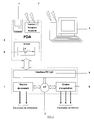
- FIG. 1 represents the block diagram of the measuring system according to the invention.
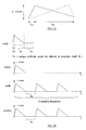
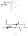
- Figure 2A schematically shows a triangular signal shape.
- Figure 2B schematically shows the parameterization of a stimulation sequence.
- FIG. 3 represents the schematic diagram of the acquisition system according to the invention.
- Figure 4 schematically shows the method of automatic gain adjustment.
- Figure 5 schematically shows an EMG signal with stimulation artifact such that V EMG > V ARTEFACT .
- FIG. 6 schematically represents an EMG signal with stimulation artifact such that V EMG ⁇ V ARTEFACT .
- Figure 7 shows the saturation of the amplifier due to excessive amplification of the stimulation artifact.
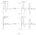
- Figure 8 shows the gain adjustment for EMG with stimulus artifact such as V ARTEFACT > V EMG .
- FIG. 9 shows the detailed block diagram of the acquisition chain.
- Figure 10A schematically shows the short-circuiting of the measuring electrodes.
- FIG. 10B schematically represents the EMG signal with stimulation artifact and short-circuiting of the measurement electrodes (synchronized acquisition at the end of the stimulation).
- FIG. 10C corresponds to the signal of FIG. 10B according to whether the system operates in synchronized mode or in level trigger mode.
- Figures 10D and 10E schematically show the triggering of the acquisition when exceeding a programmable voltage threshold independent of the stimulator.
- Figure 10F shows schematically the initiation of the acquisition at the request of the user (continuous acquisition).
- Figure 11 schematically shows networking for a polytopic measurement.
- Figure 12 schematically shows an open loop acquisition.
- Figure 13 schematically shows a closed loop acquisition in the operating room.
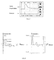
- Figure 14 graphically represents an intensity search leading to "supra-maximal" excitation.
- Figure 15 shows the amplitude of the EMG signal as a function of the intensity of the electrical pulses.
- the system according to the invention schematically illustrated in FIG. 1 comprises a current source 1 enabling the excitation of a peripheral motor nerve and an acquisition chain 2 specially adapted to the measurement of evoked electromyographic potentials.
- a microcontroller 3 responsible for controlling and synchronizing the various modules of the system in real time and communicating with the computer 4 via a standardized interface 5 (RS-232, USB, RS-485 , etc.).
- the EMG signal and / or its parameters can be viewed on the display screen 6.
- the system can be controlled from any workstation with a standard communication port (RS-232, USB, RS-485, etc.), it is best to use a PDA (Personal Digital Assistant) 4 to achieve the user interface to ensure portability, autonomy and system security (see below, section 1.7).
- PDA Personal Digital Assistant
- the system is capable of establishing a wireless communication with a central computer 8 via a "Bluetooth" transmitter / receiver 7 integrated in the PDA.
- the EMG responses can be stored in the non-volatile memory 9 available on board the PDA (SD, CompactFlash, etc.).
- the system includes a stimulator that can work in two different modes.
- the stimulator delivers user-programmable stimulation sequences.
- the second it delivers the trains of pulses usually used in anesthesia.
- the electro-stimulator contains a series of rectangular pulse sequences prerecorded in its memory, such as ST (Single Twich), TOF (Train Of Four), TS (Tetanic Stimulation) or DBS (Double Burst Stimulation) .
- ST Single Twich
- TOF Train Of Four
- TS Tetanic Stimulation
- DBS Double Burst Stimulation
- Figure 2B illustrates the parameterization of a stimulation sequence.
- the pacemaker performs regular or on demand measurement of impedance between stimulation electrodes according to medical standards for the fault current.
- the acquisition chain 2 shown diagrammatically in FIG. 3, serves to amplify the signal coming from the measurement electrodes 21 in “V 1 " using a differential amplifier 22, to filter it through a filter 25 to extract the unwanted frequencies and perform the analog / digital conversion 26 of the signal "V 2 " and conditioned.
- the automatic gain control system 23 controlled 24 from the microcontroller amplifies the input signal 21 to best exploit the voltage range of the converter.
- Stimulation causes an annoying artifact for low amplitude EMG measurement.
- the EMG signals being of relatively low amplitude and collected in a rather noisy environment, they should be amplified as much as possible and as close as possible to the measurement site.
- Figure 5 shows that for EMGs of suitable amplitude (when the patient is not curarized), the amplitude of the muscular response is generally higher than the amplitude of the stimulation artifact.
- the maximum gain of the amplifier is therefore inversely proportional to the amplitude of the EMG signal.
- the maximum gain of the amplifier therefore no longer depends on the amplitude of the EMG signal but on the amplitude of the stimulation artifact, resulting in a bad signal-to-noise ratio (SNR or signal-to- noise ratio). Ratio) for small EMGs.
- Figure 8 shows the gain adjustment for EMG with stimulation artifact such as V ARTEFACT > V EMG .
- the connector 31 can be distinguished towards the measuring electrodes and the reference electrode.
- the system performs differential pre-amplification 33 to minimize common-mode noises sensed by the human body.
- the preamplified signal "V 0 " passes through a bandpass filter 34 to keep only the useful frequencies thereof (10 - 1000 Hz).
- the filtered signal "V F " may optionally be re-amplified to best fit within the input voltage range of the analog-to-digital converter 310 (see “Mode 2" below).
- Two separate modules 311 and 312 make it possible to independently adjust the gain of the preamplifier 33 and that of the amplifier 35 via certain output tabs 38 of the microcontroller 39.
- the signal is masked.
- This method involves shorting the acquisition electrodes for the duration of the stimulation artifact. It requires that the stimulator is coupled to the EMG acquisition chain and that it provides a synchronization signal.
- the gain of the preamplifier can be optimized immediately.
- the delay between the end of the stimulation and the opening of the relay bypassing the electrodes is made programmable by the user.
- the amplification is bi-staged with intermediate filtering of the stimulation artifact.
- the system operates in synchronized mode (with short-circuiting of the measuring electrodes) or in tripping mode (without short-circuiting of the measuring electrodes) and regardless of the relative amplitude of the EMG relative to the stimulus artefact, we can always amplify the signal optimally, that is, by keeping the relative quantization error constant.
- the system is designed to operate in three different modes and its architecture is adapted to keep the quantization error constant in each mode.
- the current source and the acquisition chain being driven by the same microcontroller, it is easy to synchronize the start of the acquisition on the end of the stimulation.
- An output from the microcontroller drives a relay that short-circuits the measurement electrodes during the first microseconds after the stimulation, which has the effect of masking the artifact of stimulation and allowing the increase of the amplifier gain without risk of saturation.
- the triggering of the acquisition takes place when a programmable voltage threshold (independent of the stimulator) is exceeded.
- a circular buffer of programmable size contains the samples preceding the trigger condition.
- the system performs two-stage amplification with intermediate filtering of the stimulation artifact.
- the triggering of the acquisition is done at the request of the user.
- the system according to the invention is designed to perform regularly or on demand the impedance measurement at the levels of the acquisition electrodes.
- the system has protection resistors to limit the fault current in the event that the supply voltage is accidentally applied to the measuring electrodes.
- the system performs the acquisition of the EMG, saves the response on the non-volatile memory, displays the curve in accordance with the selected display mode, performs a curve processing and displays the determining parameters.
- the user reads the registered EMGs.
- the system reads from the device's memory, displays the signal in the selected display mode, processes the curve and displays the relevant parameters.
- the user chooses the type of sequence to be delivered (ST, TOF, %), the intensity and the width of the pulses.
- the user draws his own waveforms using the appropriate graphical tools provided.
- the gain adjustment of the amplifiers is transparent to the user.
- the system automatically adjusts the gain as seen previously.
- the user can choose both the gain of the pre-amp and the gain of the amp of the acquisition chain. 1.5.5 Display Mode The various usual display modes of the state of the art are provided. 1.5.6 Choice of critical parameters
- the evaluation of muscle relaxation can be done in particular by measuring the ratio of the peak-to-peak amplitude of the curarized EMG on the peak-to-peak amplitude of a reference EMG (for example T 1 / T 0 , T 4 / T 1 , etc.) or by measuring the ratio of the surfaces (eg S 1 / S 0 , S 4 / S 1 , etc.) of the rectified EMGs (i.e. the potentials taken in ultimate value).
- a reference EMG for example T 1 / T 0 , T 4 / T 1 , etc.
- S 1 / S 0 , S 4 / S 1 , etc. the ratio of the surfaces of the rectified EMGs (i.e. the potentials taken in ultimate value).
- the software allows for complete analysis, both in real time and post-processing.
- the device is designed to work as a "slave" of a central computer via a wireless connection.
- the central computer is also able to establish communication with several EMG stimulation-response systems and interrogate them in turn ( Figure 11).
- the EMGs are saved on the PDA memory card.
- the apparatus of the invention is first of all useful to appreciate the effect of new molecules that appear on the market and whose effects must be estimated at different sites, on different muscles.
- the time constant and the inertia of the effects of the curative agents depend on the type of drug administered to the patient and, on the other hand, the Paralysis rate is not uniform in all parts of the body.
- the device described is also useful in a neurophysiological examination for assessing muscle tone. It is often necessary to appreciate the muscular tone of a given muscle or the relation of paralysis or recovery between two muscles. Indeed, during a curare injection, the patient's paralysis begins at the central level and ends with the peripheral muscles. Likewise, muscles like the diaphragm paralyze before the muscles at the extremities, like the adductor of the thumb. The process of decurarization is done in the same order.
- the apparatus of the invention also has the possibility of networking for a polytopic measurement (see FIG. 11).
- the device is designed to slave to a central computer via a wireless connection.
- the central computer is also able to establish communication with several EMG stimulation-response systems and interrogate them in turn.
- the apparatus operates completely autonomously and provides the display of the response curve as well as a numerical value representative of the state of muscle relaxation of the patient (T 4 / T 1 or T 1 / T 0 , etc.). .
- the user may choose to configure the PDA to schedule stimulation sequences to be delivered during surgery or to administer pacing sequences on demand.
- a command 41 is sent to the microcontroller which then provides real-time management.
- the stimulator delivers the selected pulse train 42 to a peripheral motor nerve and the acquisition system measures the response of the corresponding muscle.
- the PDA receives the burst of bytes 44 from the system and provides the processing of the response (saving the response, displaying the curve and evaluating the parameters estimating the degree of neuromuscular block).
- the PDA is able to communicate with a central computer via a wireless connection "Bluetooth” or a wired connection with galvanic isolation.
- the device can thus work as slave of the master computer and integrate into a closed control loop.
- the PDA After performing the measurement of the EMG, the PDA sends information (total curve or pre-processed response) to the central computer that controls the curare injection pumps.
- the PDA operates as a slave of a WorkStation.
- the central computer periodically interrogates the stimulation-response system to control the degree of neuromuscular blockage of the patient during the surgical procedure.
- the regulation loop is of closed type.
- the central computer also controls the injection of the curare pumps.
- EMG electromyography
- Stimulation of sufficient intensity will cause the reaction of all the muscle fibers and the response obtained will be maximal in amplitude.
- Figure 14 shows the EMG obtained as the intensity of the stimulation current source is gradually increased.
- the amplitude of the response signal increases with the intensity of the current pulses until saturation is reached. This saturation indicates that all the muscle fibers are actually excited and the response reaches a maximum amplitude.
- the weakening of the maximal response can be related to the state of relaxation of the muscle.
- the intensity of this stimulation will therefore be 20 to 25 percent higher than that for which we obtain a maximum response, hence the qualifier "supra-maximal".
- Figure 15 shows the amplitude of the EMG signal as a function of the intensity of the electrical pulses
- the threshold characterized by the saturation of the amplitude, depends strongly on one muscle to the other and even from one patient to another.
- Some devices such as the currently used TOF-Watch (in accelerometry) are programmed by default to 50 mA to ensure that they are above the saturation threshold and that the muscle is properly excited.
- the microcontroller can determine very precisely the intensity of the electrical pulses leading to a super-maximum excitation.
- EMG muscle relaxation rate evaluation
- the apparatus of the invention can be advantageously used in intensive care unit (ICU); the reduction in the size of the device (portability) allows measurements of evoked potentials directly in the patient's bed, during the postoperative period in the recovery room for example.
- ICU intensive care unit
- the apparatus of the invention may be useful in the home of the patient who is recovering muscle.
- patients can have a portable electro-stimulator they use at home (example: belt to build muscles).
Abstract
Description
La présente invention se rapporte à un nouvel appareil de mesure d'électromyogrammes.The present invention relates to a new apparatus for measuring electromyograms.
Lorsqu'un muscle est en activité, il est possible de recueillir un signal (bio)électrique de faible amplitude en plaçant des électrodes sur celui-ci. L'ensemble de ces signaux, se présentant sous forme de potentiels électriques, est appelé électromyogramme (EMG).When a muscle is active, it is possible to collect a small electrical (bio) signal by placing electrodes on it. All of these signals, in the form of electrical potentials, is called electromyogram (EMG).
Le but d'une analyse EMG est d'obtenir de l'information sur l'état et le fonctionnement des muscles par la quantification de l'activité électromusculaire. Cette mesure est effectuée au moyen d'électrodes appliquées sur ou sous la peau. Un signal est détecté, traduisant l'activité du muscle sous-jacent.The goal of EMG analysis is to obtain information on the state and function of muscles by quantifying electromuscular activity. This measurement is performed by means of electrodes applied on or under the skin. A signal is detected, reflecting the activity of the underlying muscle.
On connaît l'électro-stimulation qui consiste à exciter un nerf moteur périphérique à l'aide d'impulsions électriques pour provoquer, de manière externe, donc sans l'intermédiaire du cerveau, la réaction du muscle qui lui est associée.Electro-stimulation is known which consists of exciting a peripheral motor nerve with the help of electrical impulses to provoke, externally, therefore without the intermediary of the brain, the reaction of the muscle which is associated with it.
Il convient donc de distinguer les signaux EMG, résultant d'une stimulation électrique, des signaux EMG spontanés, résultant d'un mouvement volontaire du muscle.It is therefore necessary to distinguish EMG signals, resulting from electrical stimulation, from spontaneous EMG signals resulting from a voluntary movement of the muscle.
Lors d'une anesthésie générale, différentes drogues sont injectées au patient et ont pour but :
- d'assurer l'amnésie et le sommeil par l'inconscience ;
- d'insensibiliser à la douleur par l'analgésie et
- de permettre le relâchement musculaire.
- to ensure amnesia and sleep by unconsciousness;
- to numb the pain with analgesia and
- to allow muscle relaxation.
Le curare diminuant le nombre de fibres musculaires actives, on recourt aux EMG pour évaluer le taux de relâchement musculaire.As curare decreases the number of active muscle fibers, EMG is used to evaluate the rate of muscle relaxation.
Cette évaluation du relâchement musculaire est confrontée à un certain nombre de difficultés de mesure :
- une diminution de l'amplitude des EMG au cours de la curarisation ;
- un environnement bruité, notamment par la pollution électromagnétique ;
- l'exigence que la phase d'initialisation, c'est-à-dire le temps de pose des électrodes et le calibrage de l'appareil, soit relativement courte.
- a decrease in the amplitude of EMG during curarization;
- a noisy environment, in particular electromagnetic pollution;
- the requirement that the initialization phase, that is to say the electrode placement time and the calibration of the device, be relatively short.
Le brevet US-A-4 291 705 décrit un appareil permettant de déterminer le degré de paralysie neuromusculaire, en effectuant une stimulation "supra-maximale" (voir ci-après, § [0157] et suivants) d'un nerf moteur périphérique. Cet appareil intègre le signal EMG redressé et affiche le résultat. L'état de paralysie est indiqué en mesurant le rapport de la surface de l'EMG curarisé sur la surface de l'EMG de référence, c'est-à-dire celui obtenu avant les premières injections de curare.US-A-4,291,705 discloses an apparatus for determining the degree of neuromuscular palsy by performing "supra-maximal" stimulation (see below, § [0157] and following) of a peripheral motor nerve. This device incorporates the rectified EMG signal and displays the result. The state of paralysis is indicated by measuring the ratio of the EMG surface curarized on the surface of the EMG of reference, that is to say that obtained before the first curare injections.
Le système décrit est entièrement analogique et fournit un signal de sortie proportionnel au rapport des surfaces des signaux EMG redressés. Ce signal analogique est dirigé vers l'afficheur et vers l'enregistreur.The system described is entirely analog and provides an output signal proportional to the ratio of the surfaces of the rectified EMG signals. This analog signal is directed to the display and to the recorder.
Le stimulateur peut délivrer une impulsion unique, une série rapide d'impulsions ou un nombre prédéterminé d'impulsions à intervalles de temps réguliers mais n'est pas capable de fournir d'autres formes d'ondes que des rectangles (par exemple de 200 µs de durée).The stimulator can deliver a single pulse, a rapid series of pulses or a number predetermined pulse at regular time intervals but is not able to provide other waveforms than rectangles (eg 200 μs duration).
Ce système comporte un module destiné à gérer le retard entre le stimulateur et la chaîne d'acquisition afin de contrôler le début de l'intégration. Il n'y a pas de déclenchement par niveau.This system includes a module for managing the delay between the pacemaker and the acquisition chain in order to control the beginning of the integration. There is no trigger by level.
La demande de brevet GB-A-2 113 846 décrit un système de contrôle de l'état d'un patient lors d'une anesthésie réalisant une mesure d'EEG (électroencéphalogramme) couplée à des mesures d'EMG. Un système de stimulation-réponse permet de mesurer le taux de relâchement musculaire en stimulant un nerf moteur et en mesurant la réponse du muscle correspondant. Les courbes sont enregistrées et affichées en temps réel.GB-A-2,113,846 describes a system for monitoring the state of a patient during anesthesia performing EEG measurement (electroencephalogram) coupled with EMG measurements. A stimulation-response system measures the rate of muscle relaxation by stimulating a motor nerve and measuring the response of the corresponding muscle. The curves are recorded and displayed in real time.
Il n'y a pas de description du système de stimulation-réponse, ni de la méthode de mesure pour évaluer le taux de décontraction musculaire. On utilise un "train de quatre" (Train of Four, TOF), c'est-à-dire quatre impulsions électriques séparées d'une demi-seconde. Pour chaque impulsion électrique, le système affiche une barre d'histogramme représentant la surface (intégrale) de l'EMG redressé correspondant. Le système comprend un convertisseur analogique/numérique (CAN) et une mémoire pour stocker les informations affichéesThere is no description of the stimulation-response system, nor of the measurement method to evaluate the rate of muscular decontraction. A " Four of a Train " ( TOF) is used, that is, four electrical pulses separated by half a second. For each electrical pulse, the system displays a histogram bar representing the (integral) surface of the corresponding rectified EMG. The system includes an analog-to-digital converter (ADC) and a memory for storing the information displayed
Le brevet américain US-A-4 595 018 décrit une méthode logicielle pour mesurer la transmission neuromusculaire (NMT). Les mesures sont entachées d'un artefact de stimulation. Pendant la phase de calibrage, l'appareil effectue une première mesure et mémorise la valeur de l'artefact de stimulation. En numérisant les informations collectées, l'erreur sur la mesure est éliminée mathématiquement. Cette méthode présente le désavantage que l'artefact perturbe malgré tout la chaîne de mesure.US-A-4,595,018 discloses a software method for measuring neuromuscular transmission (NMT). The measurements are tainted with a stimulating artifact. During the calibration phase, the instrument makes a first measurement and stores the value of the stimulation artifact. By digitizing the collected information, the measurement error is eliminated mathematically. This method presents the disadvantage that the artifact still disturbs the measurement chain.
Le document KR-A-9 004 899 décrit un appareil comprenant un capteur EMG pour la détection d'un signal électrique le long d'un tissu musculaire, un amplificateur EMG pour le filtrage et l'amplification du signal détecté, un afficheur, un contrôleur du signal pour l'analyse en temps réel du signal EMG et pour la réalisation de calculs à grande vitesse sur le signal, ainsi qu'un stimulateur pour la transmission d'un signal stimulus à la surface du tissu musculaire.Document KR-A-9,004,899 describes an apparatus comprising an EMG sensor for detecting an electrical signal along a muscle tissue, an EMG amplifier for filtering and amplifying the detected signal, a display, a signal controller for the real-time analysis of the EMG signal and for performing high-speed calculations on the signal, as well as a stimulator for the transmission of a stimulus signal to the surface of the muscle tissue.
Le brevet US-A-5 300 096 décrit un stimulateur musculaire électrique permettant d'obtenir des signaux électromyographiques (EMG) numériques pour l'analyse et l'affichage par un programme d'ordinateur. Le système travaille par stimulation-réponse, c'est-à-dire excitation électrique d'un nerf moteur suivie par l'acquisition du signal EMG associé.US-A-5,300,096 discloses an electrical muscle stimulator for obtaining digital electromyographic (EMG) signals for analysis and display by a computer program. The system works by stimulation-response, that is to say, electrical excitation of a motor nerve followed by the acquisition of the associated EMG signal.
Le stimulateur délivre un train d'impulsions thérapeutique pré-sélectionné. Un circuit d'interconnexion permet de relier le système d'acquisition déclenchable par niveau, le stimulateur et l'ordinateur. Le software permet de gérer la période, l'intensité, etc., des impulsions électriques, le seuil de déclenchement du système d'acquisition et l'affichage en temps réel.The stimulator delivers a pre-selected therapeutic pulse train. An interconnecting circuit connects the triggerable acquisition system by level, the stimulator and the computer. The software manages the period, the intensity, etc., of the electrical pulses, the triggering threshold of the acquisition system and the real-time display.
Le principe du système est similaire à celui décrit dans le brevet US-A-4 291 705 mais sous forme numérique, ce qui nécessite un PC.The principle of the system is similar to that described in US Pat. No. 4,291,705 but in digital form, which requires a PC.
Le brevet US-A-6 224 549 décrit un système de monitoring médical pour signaux électrophysiologiques de différents types (EEG, EMG, EP ou Evoked Potential) comprenant :
- un ordinateur pour l'affichage et la mémorisation de la courbe ;
- une interface utilisateur implantée dans le PC.
- a computer for displaying and memorizing the curve;
- a user interface implanted in the PC.
Ce système stocke la réponse sur le disque dur et l'affiche. L'interface utilisateur comporte un jeu de panneaux qui permettent d'afficher un ou plusieurs signaux. On dispose d'un certain nombre d'options d'affichage (trigger, calcul de la moyenne, analyse spectrale). Le signal affiché peut être généré à partir d'un stimulateur auditif, visuel ou électrique. Le système adapte la bande passante en fonction du type de signal mesuré (EMG, EEG, ...) .This system stores the response on the hard drive and displays it. The user interface includes a set of panels that display one or more signals. There are a number of display options (trigger, averaging, spectral analysis). The displayed signal can be generated from an auditory, visual or electrical stimulator. The system adapts the bandwidth according to the type of signal measured (EMG, EEG, ...).
Ce document ne donne pas de description de la chaîne d'acquisition et du stimulateur. Le brevet porte essentiellement sur le software (interface utilisateur). Un désavantage est la nécessité de disposer d'un PC, d'où perte de portabilité, sécurité, etc. (voir section 1.7).This document does not give a description of the acquisition chain and pacemaker. The patent is essentially about the software (user interface). A disadvantage is the need for a PC, resulting in loss of portability, security, etc. (see section 1.7).
L'utilisateur peut choisir le type de stimulateur (électrique, auditif ou visuel).The user can choose the type of stimulator (electrical, auditory or visual).
La demande internationale WO-A-02 053012 décrit un appareil digital d'électrodiagnostic clinique pour la mesure d'électromyographie (EMG) et/ou de conduction nerveuse. Le système comporte une paire d'électrodes de mesure, un amplificateur, un filtre et un stimulateur. Le stimulateur et la chaîne d'acquisition sont connectés à l'entrée stéréo d'une carte multimédia intégrée à un PC. Il existe une isolation galvanique entre le PC et la chaîne d'acquisition. Le système est déclenchable par niveau. Un désavantage est également la nécessité de disposer d'un PC, d'où perte de portabilité, sécurité, etc. (voir section 1.7).International Application WO-A-02 053012 discloses a digital clinical electrodiagnostic apparatus for the measurement of electromyography (EMG) and / or nerve conduction. The system includes a pair of measuring electrodes, an amplifier, a filter and a stimulator. The pacemaker and the acquisition system are connected to the stereo input of a multimedia card integrated into a PC. Galvanic isolation exists between the PC and the acquisition system. The system is triggerable by level. A disadvantage is also the need to have a PC, resulting in loss of portability, security, etc. (see section 1.7).
La demande internationale WO-A-99 41682 décrit un programme s'exécutant sur un PDA et permettant d'entrer des données relatives à un patient. Le PDA est également capable de se connecter à un réseau d'ordinateurs pour échanger des informations avec une base de données. Le système comporte une interface qui permet de collecter des signaux sur le patient.International application WO-A-99 41682 discloses a program running on a PDA and allowing to enter data relating to a patient. The PDA is also able to connect to a computer network to exchange information with a database. The system has an interface that allows to collect signals on the patient.
Dans "MIThril 2003 : Applications and Architecture", Rich De Vaul, Michael Sung, Jonathan Gips, Alex "Sandy" Pentland, Media Laboratory, Massachusetts Institute of Technology, on décrit l'utilisation d'un PDA pour mesurer des signaux de type "biopotentiels" et communiquer avec un ordinateur central via une liaison sans fil. Cet article traite surtout de l'aspect informatique et réseau du système qui permet de faire des mesures telles que : EMG, ECG (électrocardiogramme), EEG, température, accélération, etc.In "MIThril 2003: Applications and Architecture", Rich De Vaul, Michael Sung, Jonathan Gips, Alex "Sandy" Pentland, Media Laboratory, Massachusetts Institute of Technology, describes the use of a PDA to measure biopotential "and communicate with a central computer via a wireless link. This article deals mainly with the computer and network aspect of the system that allows measurements such as: EMG, ECG (electrocardiogram), EEG, temperature, acceleration, etc.
Dans "Biosignals Offer Potential for Direct Interfaces and Health Monitoring", Vince Stanford, Pervasive Computing, IEEE, January-March 2004, pp. 99-103, on traite également de l'acquisition de signaux électrophysiologiques à l'aide d'un PDA sur n'importe quelle partie du corps. Le PDA peut établir une communication sans fil avec un ordinateur central et envoyer les résultats de la mesure à distance.In "Biosignals Potential Offer for Direct Interfaces and Health Monitoring," Vince Stanford, Pervasive Computing, IEEE, January-March 2004, pp. 99-103, we also discuss the acquisition of electrophysiological signals using a PDA on any part of the body. The PDA can establish wireless communication with a central computer and send the measurement results remotely.
Dans "Mobile biosignal acquisition and processing on the Pocket PC", g.MOBIlab (www.gtec.at/products/g.MOBIlab/ gMOBIlab.htm), on décrit un système permettant l'acquisition d'EEG, EMG, ECG, de pulsations cardiaques, etc., à l'aide d'un Pocket PC. ce système permet :
- la visualisation et l'enregistrement de jusqu'à 8 canaux simultanément ;
- le transfert des données (bio-signaux) à l'hôpital via GSM ou WAN ;
- la détermination de la position du sujet grâce à un module GPS.
- viewing and recording of up to 8 channels simultaneously;
- transfer of data (bio-signals) to the hospital via GSM or WAN;
- determining the position of the subject with a GPS module.
Ce système est notamment utilisé pour mesurer l'effet des hautes altitudes sur les paramètres des EEG et des ECG.This system is used to measure the effect of high altitudes on EEG and ECG parameters.
Dans "A Wireless Multi-Channel Data Acquisition System for Physiological Signals", J. Stefan Karlsson, Tomas Bäcklund, Urban Edström, Department of Biomédical Engineering and Informatics, University Hospital, Umea, Sweden and Centre for Biomedical Engineering and Physics, Umea University, Sweden, un module spécifique conditionne le signal d'entrée, effectue une CAN du signal et le transmet au PC via une connexion sans fil (Bluetooth). Le software à bord du PC permet de collecter les données en temps réel, de visualiser les réponses et de stocker les échantillons. Le système, basé sur un système de transmission sans fil, est suffisamment performant pour permettre l'acquisition de tous les signaux électrophysiologiques.In " A Wireless Multi-Channel Data Acquisition System for Physiological Signals", J. Stefan Karlsson, Tomas Bäcklund, Urban Edström, Department of Biomedical Engineering and Informatics, University Hospital, Umea, Sweden and Center for Biomedical Engineering and Physics, Umea University, Sweden, a specific module conditions the input signal, carries out a signal CAN and transmits it to the PC via a wireless connection (Bluetooth). The software on board the PC can collect data in real time, view responses and store samples. The system, based on a wireless transmission system, is sufficiently powerful to allow acquisition of all electrophysiological signals.
On trouve dans le commerce des instruments permettant de réaliser des mesures EMG.There are commercially available instruments for performing EMG measurements.
DATAQ Instruments Inc. (Akron, Ohio) propose une chaîne d'acquisition modulaire (hardware et software) comprenant un préamplificateur faible bruit permettant le conditionnement de signaux électrophysiologiques, en particulier EMG.DATAQ Instruments Inc. (Akron, Ohio) offers a modular hardware and software acquisition chain including a low noise preamplifier for electrophysiological signal conditioning, in particular EMG.
Cet appareil présente le désavantage d'un réglage manuel du gain d'amplificateur et de ne pas comporter de stimulateur.This apparatus has the disadvantage of manual adjustment of the amplifier gain and does not include a stimulator.
MEGA Electronics Inc. (New Brunswick, New Jersey) propose un appareil pratique et portable que le travailleur peut emmener sur lui pour mesurer des informations telles que :
- l'importance de l'effort physique nécessaire au maintien d'une position particulière ;
- les phases de la tâche professionnelle qui impliquent une charge statique ;
- le niveau des pics de charge ;
- le développement éventuel d'une fatigue musculaire lors de l'accomplissement de l'activité ;
- une comparaison entre les tâches ;
- une comparaison entre les individus.
- the importance of the physical effort required to maintain a particular position;
- the phases of the professional task that involve a static load;
- the level of load peaks;
- the possible development of muscle fatigue during the performance of the activity;
- a comparison between the tasks;
- a comparison between individuals.
Les signaux peuvent être envoyés immédiatement par une connexion filaire vers un ordinateur pour une analyse plus approfondie, ou bien être enregistrés afin d'éviter l'emploi d'un câble de connexion entre l'opérateur et l'ordinateur.Signals can be sent immediately via a wired connection to a computer for further analysis, or recorded to avoid the use of a connection cable between the operator and the computer.
Cet appareil présente la caractéristique unique que la synchronisation avec des images vidéo digitales est possible. De cette façon, on peut examiner précisément quelle position implique une charge musculaire statique.This device has the unique feature that synchronization with digital video images is possible. In this way, one can examine precisely which position involves a static muscular load.
Les désavantages de cet appareil sont l'absence de stimulateur, de liaison sans fil et d'affichage sur l'appareil, ainsi que le manque d'autonomie.The disadvantages of this device are the lack of stimulator, wireless link and display on the device, as well as lack of autonomy.
En anesthésie, on utilise spécifiquement des appareils basés à la fois sur :
- l'observation visuelle de la contraction (par ex. TOF-Watch®, Organon, Akzo Nobel). Un premier inconvénient de cet appareil est que la mesure est qualitative ;
- la mécanomyographie : utilisation d'une jauge de contrainte et mesure de force. L'inconvénient réside ici dans la difficulté de calibration. D'où, comme F = m.a, on recourt à une mesure d'accélération (indirecte) ;
- l'accélérométrie : mesure indirecte de l'activité musculaire par des mesures d'accélération. Les inconvénients sont que la mesure ne peut être réalisée que sur la main et qu'elle est en outre subjective et peu reproductible.
- visual observation of the contraction (eg TOF-Watch®, Organon, Akzo Nobel). A first disadvantage of this apparatus is that the measurement is qualitative;
- mechanomyography: use of a strain gauge and measurement of force. The disadvantage here lies in the difficulty of calibration. From where, like F = ma, one resorts to a measure of acceleration (indirect);
- accelerometry: indirect measurement of muscle activity by acceleration measurements. The disadvantages are that measurement can only be done on the hand and is subjective and not very reproducible.
Ainsi, dans l'appareil TOF-Watch®, le stimulateur permet de fournir les trains d'ondes habituellement utilisés en anesthésie (par ex. ST, TOF, TETANOS, DBS), un accéléromètre permet de mesurer l'accélération du pouce (mesure indirecte de la force) et l'appareil affiche le rapport entre l'accélération de la quatrième et de la première flexion.Thus, in the TOF-Watch® device, the stimulator can supply the wave trains usually used in anesthesia (eg ST, TOF, TETANOS, DBS), an accelerometer can measure the acceleration of the thumb (measurement indirect force) and the device displays the ratio between the acceleration of the fourth and the first bending.
La présente invention vise à proposer une solution qui permette de s'affranchir des inconvénients de l'état de la technique.The present invention aims to propose a solution that makes it possible to overcome the drawbacks of the state of the art.
En particulier, l'invention vise à fournir un appareil de mesure de signaux électrophysiologiques de type EMG consécutifs à une électro-stimulation, qui soit portable, autonome, très peu encombrant, fiable, flexible, simple d'utilisation, conforme aux normes de sécurité électriques (limitation du courant de défaut) et de fabrication peu coûteuse.In particular, the object of the invention is to provide a device for measuring electrophysiological signals of EMG type consecutive to electro-stimulation, which is portable, autonomous, very compact, reliable, flexible, easy to use, compliant with safety standards electrical (fault current limitation) and inexpensive manufacturing.
Un but complémentaire de l'invention est de fournir un appareil qui puisse effectuer des mesures fiables malgré la diminution d'amplitude des signaux EMG au cours de la curarisation lors d'une anesthésie.An additional object of the invention is to provide an apparatus that can perform reliable measurements despite the decrease in amplitude of the EMG signals during curarization during anesthesia.
Un autre but de l'invention est de permettre un contrôle aisé et automatique de la pose correcte des électrodes de mesure.Another object of the invention is to allow easy and automatic control of the correct laying of the measuring electrodes.
Un autre but de l'invention est de permettre un calibrage rapide de l'appareil, eu égard à un éventuel artefact de stimulation, ainsi qu'une détermination précise de l'amplitude de l'excitation supra-maximale.Another object of the invention is to allow a quick calibration of the device, with regard to a possible stimulation artefact, as well as an accurate determination of the amplitude of the supra-maximal excitation.
Un but encore complémentaire de l'invention est de fournir un appareil capable d'être relié ou piloté par un (réseau d') ordinateur(s) distant(s), éventuellement grâce à une connexion sans fil.A further object of the invention is to provide a device capable of being connected or controlled by a remote network of computers, possibly through a wireless connection.
Un premier objet de la présente invention se rapporte à un appareil intégré, portable et autonome pour la mesure directe, l'affichage, le traitement et la transmission à distance de signaux électromyographiques (EMG) décrit selon les termes de la revendication 1. L'innovation réside dans l'adaptation automatique du gain d'amplification du signal EMG mesuré en combinaison avec le traitement de l'artefact inévitable de stimulation, de manière à optimiser l'usage de la résolution du convertisseur analogique/numérique du système. En d'autres termes, l'invention fournit un contrôle automatique de gain avec une précision maximale (c'est-à-dire une erreur relative de quantification minimale).A first object of the present invention relates to an integrated, portable and autonomous apparatus for the direct measurement, display, processing and remote transmission of electromyographic (EMG) signals described in the terms of
Une utilisation de prédilection de cet appareil est l'évaluation du taux de relâchement musculaire au cours de la curarisation pratiquée lors d'une anesthésie. La résolution est conservée, même lorsque l'amplitude du signal EMG diminue au cours du temps, comme c'est le cas dans cette application. De plus, l'invention contribue à résoudre le problème de la diminution du rapport signal-sur-bruit liée à la diminution de l'amplitude du signal EMG lors de la curarisation. De manière plus générale, l'invention permet une mesure efficace dans un environnement bruité (pollution électromagnétique).A preferred use of this device is the evaluation of the rate of muscle relaxation during the curarization performed during anesthesia. The resolution is maintained even when the amplitude of the EMG signal decreases over time, as is the case in this application. In addition, the invention contributes to solving the problem of the decrease in the signal-to-noise ratio related to the decrease in the amplitude of the EMG signal during curarization. More generally, the invention allows effective measurement in a noisy environment (electromagnetic pollution).
Des formes d'exécutions préférées de l'invention sont détaillées dans les revendications subsidiaires 2 à 21.Preferred embodiments of the invention are detailed in subsidiary claims 2 to 21.
Un second objet de la présente invention est décrit dans les revendications 22 et 23 qui concernent un procédé pour ajuster automatiquement le gain appliqué au signal d'entrée et conserver la résolution maximale du convertisseur analogique/numérique dans l'appareil de mesure susmentionné, tout en supprimant ou en atténuant l'artefact de stimulation, selon que cet appareil est utilisé respectivement en mode de déclenchement synchronisé sur la stimulation ou en mode de déclenchement par niveau.A second object of the present invention is described in
La figure 1 représente le schéma bloc du système de mesure selon l'invention.FIG. 1 represents the block diagram of the measuring system according to the invention.
La figure 2A représente schématiquement une forme de signal triangulaire.Figure 2A schematically shows a triangular signal shape.
La figure 2B représente schématiquement le paramétrage d'une séquence de stimulation.Figure 2B schematically shows the parameterization of a stimulation sequence.
La figure 3 représente le schéma de principe de la chaîne d'acquisition selon l'invention.FIG. 3 represents the schematic diagram of the acquisition system according to the invention.
La figure 4 représente schématiquement le procédé d'ajustement automatique du gain.Figure 4 schematically shows the method of automatic gain adjustment.
La figure 5 représente schématiquement un signal EMG avec artefact de stimulation tel que VEMG > VARTEFACT.Figure 5 schematically shows an EMG signal with stimulation artifact such that V EMG > V ARTEFACT .
La figure 6 représente schématiquement un signal EMG avec artefact de stimulation tel que VEMG < VARTEFACT.FIG. 6 schematically represents an EMG signal with stimulation artifact such that V EMG <V ARTEFACT .
La figure 7 montre la saturation de l'amplificateur suite à une amplification trop importante de l'artefact de stimulation.Figure 7 shows the saturation of the amplifier due to excessive amplification of the stimulation artifact.
La figure 8 montre l'ajustement du gain pour un EMG avec artefact de stimulation tel que VARTEFACT.> VEMG.Figure 8 shows the gain adjustment for EMG with stimulus artifact such as V ARTEFACT > V EMG .
La figure 9 montre le schéma bloc détaillé de la chaîne d'acquisition.Figure 9 shows the detailed block diagram of the acquisition chain.
La figure 10A représente schématiquement la mise en court-circuit des électrodes de mesure.Figure 10A schematically shows the short-circuiting of the measuring electrodes.
La figure 10B représente schématiquement le signal EMG avec artefact de stimulation et mise en court-circuit des électrodes de mesure (acquisition synchronisée sur la fin de la stimulation).FIG. 10B schematically represents the EMG signal with stimulation artifact and short-circuiting of the measurement electrodes (synchronized acquisition at the end of the stimulation).
La figure 10C correspond au signal de la figure 10B selon que le système fonctionne en mode synchronisé ou en mode de déclenchement par niveau.FIG. 10C corresponds to the signal of FIG. 10B according to whether the system operates in synchronized mode or in level trigger mode.
Les figures 10D et 10E montrent schématiquement le déclenchement de l'acquisition lors du dépassement d'un seuil de tension programmable indépendant du stimulateur.Figures 10D and 10E schematically show the triggering of the acquisition when exceeding a programmable voltage threshold independent of the stimulator.
La figure 10F montre schématiquement le déclenchement de l'acquisition à la demande de l'utilisateur (acquisition continue).Figure 10F shows schematically the initiation of the acquisition at the request of the user (continuous acquisition).
La figure 11 représente schématiquement la mise en réseau pour une mesure polytopique.Figure 11 schematically shows networking for a polytopic measurement.
La figure 12 représente schématiquement une acquisition en boucle ouverte.Figure 12 schematically shows an open loop acquisition.
La figure 13 représente schématiquement une acquisition en boucle fermée, en salle d'opération.Figure 13 schematically shows a closed loop acquisition in the operating room.
La figure 14 représente graphiquement une recherche d'intensité menant à une excitation "supra-maximale".Figure 14 graphically represents an intensity search leading to "supra-maximal" excitation.
La figure 15 représente l'amplitude du signal EMG en fonction de l'intensité des impulsions électriques.Figure 15 shows the amplitude of the EMG signal as a function of the intensity of the electrical pulses.
Le système selon l'invention illustré schématiquement sur la figure 1, comporte une source de courant 1 permettant l'excitation d'un nerf moteur périphérique et une chaîne d'acquisition 2 spécialement adaptée à la mesure des potentiels électromyographiques évoqués.The system according to the invention schematically illustrated in FIG. 1 comprises a
Au coeur du système on trouve un microcontrôleur 3 chargé d'assurer le pilotage et la synchronisation des différents modules du système en temps réel ainsi que la communication avec l'ordinateur 4 via une interface standardisée 5 (RS-232 , USB, RS-485, etc.).At the heart of the system is a
Le signal EMG et/ou ses paramètres peuvent être visualisés sur l'écran d'affichage 6.The EMG signal and / or its parameters can be viewed on the
Bien que le système puisse être piloté à partir de n'importe quelle station de travail comportant un port de communication standard (RS-232, USB, RS-485, etc.), il convient d'utiliser de préférence un PDA (Personal Digital Assistant) 4 pour réaliser l'interface utilisateur afin d'assurer la portabilité, l'autonomie et la sécurité du système (voir ci-après, section 1.7).Although the system can be controlled from any workstation with a standard communication port (RS-232, USB, RS-485, etc.), it is best to use a PDA (Personal Digital Assistant) 4 to achieve the user interface to ensure portability, autonomy and system security (see below, section 1.7).
Afin de faciliter son intégration dans un système de monitoring médical, le système est capable d'établir une communication sans fil avec un ordinateur central 8 via un émetteur/récepteur "Bluetooth" 7 intégré dans le PDA.In order to facilitate its integration into a medical monitoring system, the system is capable of establishing a wireless communication with a central computer 8 via a "Bluetooth" transmitter /
Les réponse EMG peuvent être enregistrées dans la mémoire non-volatile 9 disponible à bord du PDA (SD, CompactFlash, etc.).The EMG responses can be stored in the
L'invention comprend également un programme 6 servant d'interface à l'utilisateur et permettant d'exploiter les données provenant du système embarqué.
L'utilisateur peut choisir :
- le mode d'acquisition du système :
- mode synchronisé ;
- mode déclenché par niveau ;
- mode continu.
- le mode d'affichage de la courbe réponse ;
- le type de stimulation à délivrer ; etc.
The user can choose:
- the mode of acquisition of the system:
- synchronized mode;
- level triggered mode;
- continuous mode.
- the display mode of the response curve;
- the type of stimulation to deliver; etc.
La suite de la description est consacrée à chacun des modules cités ci-dessus et met en évidence les avantages qui résultent du regroupement de ces modules dans un même appareil.The remainder of the description is devoted to each of the modules mentioned above and highlights the advantages that result from the grouping of these modules in the same device.
Le système comporte un stimulateur pouvant travailler dans deux modes différents. Dans le premier mode, le stimulateur délivre des séquences de stimulation programmables par l'utilisateur. Dans le second, il délivre les trains d'impulsions habituellement utilisés en anesthésie.The system includes a stimulator that can work in two different modes. In the first mode, the stimulator delivers user-programmable stimulation sequences. In the second, it delivers the trains of pulses usually used in anesthesia.
L'électro-stimulateur contient une série de séquences d'impulsions rectangulaires préenregistrées dans sa mémoire, tels que le ST (Single Twich), le TOF (Train Of Four), le TS (Tetanic Stimulation) ou le DBS (Double Burst Stimulation).The electro-stimulator contains a series of rectangular pulse sequences prerecorded in its memory, such as ST (Single Twich), TOF (Train Of Four), TS (Tetanic Stimulation) or DBS (Double Burst Stimulation) .
L'intensité, la largeur des impulsions et la période entre deux séquences successives ont une valeur par défaut mais sont reparamétrables par l'utilisateur dans la gamme :
- amplitude des impulsions : 0 - 150
mA dans 5 kΩ ; - largeur des impulsions : 0 - 1000 µs ;
- période séparant deux séquences successives : 10 - 60 s.
- pulse amplitude: 0 - 150 mA in 5 kΩ;
- pulse width: 0 - 1000 μs ;
- period between two successive sequences: 10 - 60 s.
L'utilisateur peut choisir à la fois la forme du signal (sinusoïdale, triangulaire, rectangulaire, de forme arbitraire), sa fréquence et son amplitude.
Rectangulaire :
- amplitude : 0 - 100
mA dans 5 kΩ ; - largeur des impulsions : 0 - 1000 µs.
- amplitude : 0 - 100
mA dans 5 kΩ; - temps de montée (Tm) : 15 µs - 5 ms ;
- temps de descente (Td) : 15 µs - 5 ms.
- amplitude : 0 - 100 mA ;
- fréquence : 0 - 200 Hz.
Rectangular:
- amplitude: 0 - 100 mA in 5 kΩ;
- pulse width: 0 - 1000 μs .
- amplitude: 0 - 100 mA in 5 kΩ;
- rise time (Tm): 15 μs - 5 ms;
- descent time (Td): 15 μs - 5 ms.
- amplitude: 0 - 100 mA;
- frequency: 0 - 200 Hz.
Une fois le motif établi, l'utilisateur peut choisir de travailler en mode :
- mono-impulsion : pour délivrer un motif unique ;
- multi-impulsion : pour délivrer un nombre déterminé de motifs en fixant le temps "Ta" entre deux motifs consécutifs ;
- continu : pour électro-stimuler en continu en fixant le temps "Ta" qui sépare deux motifs consécutifs.
- mono-pulse: to deliver a single pattern;
- multi-pulse : to deliver a determined number of patterns by setting the time "T a " between two consecutive patterns;
- continuous : to electro-stimulate continuously by fixing the time "T a " which separates two consecutive patterns.
La figure 2B illustre le paramétrage d'une séquence de stimulation.Figure 2B illustrates the parameterization of a stimulation sequence.
Le stimulateur effectue régulièrement ou à la demande la mesure d'impédance entre les électrodes de stimulation selon les normes médicales pour le courant de défaut.The pacemaker performs regular or on demand measurement of impedance between stimulation electrodes according to medical standards for the fault current.
La chaîne d'acquisition 2, représentée schématiquement sur la figure 3, a pour rôle d'amplifier le signal provenant des électrodes de mesure 21 en "V1" à l'aide d'un amplificateur différentiel 22, de le filtrer à travers un filtre 25 pour en extraire les fréquences indésirables et d'effectuer la conversion analogique/numérique 26 du signal "V2" ainsi conditionné.The
Pour assurer une résolution maximale dans la conversion analogique numérique 26, le système de réglage automatique du gain 23 commandé 24 à partir du microcontrôleur permet d'amplifier le signal d'entrée 21 afin d'exploiter au mieux la plage de tension du convertisseur.To ensure maximum resolution in the
En choisissant comme gain (voir figure 4): 
où :
- VREF est la demi plage d'entrée du convertisseur analogique numérique et
- VMAX est la valeur de crête du signal à mesurer, l'amplitude du signal "V2" à l'entrée du convertisseur exploitera la "totalité" de sa plage de tension. Toujours selon la figure 4, on a :


or :
- V REF is the half input range of the digital analog converter and
- V MAX is the peak value of the signal to be measured, the amplitude of the signal "V 2 " at the input of the converter will exploit the "totality" of its voltage range. Still according to Figure 4, we have:
La stimulation provoque un artefact gênant pour la mesure d'EMG de faible amplitude.Stimulation causes an annoying artifact for low amplitude EMG measurement.
Les signaux EMG étant d'amplitude relativement faible et collectés dans un environnement assez bruité, il convient de les amplifier au maximum et le plus près possible du site de mesure.The EMG signals being of relatively low amplitude and collected in a rather noisy environment, they should be amplified as much as possible and as close as possible to the measurement site.
La figure 5 montre que, pour des EMG d'amplitude convenable (lorsque le patient n'est pas curarisé), l'amplitude de la réponse musculaire est généralement plus élevée que l'amplitude de l'artefact de stimulation.Figure 5 shows that for EMGs of suitable amplitude (when the patient is not curarized), the amplitude of the muscular response is generally higher than the amplitude of the stimulation artifact.
La condition (1) et VMAX = VEMG impliquent que 
Le gain maximum de l'amplificateur est donc inversement proportionnel à l'amplitude du signal EMG.The maximum gain of the amplifier is therefore inversely proportional to the amplitude of the EMG signal.
Comme l'augmentation de la concentration de curare provoque une diminution progressive et considérable de l'amplitude des EMG, il arrive un moment où l'amplitude de l'EMG devient inférieure à celle de l'artefact de stimulation (voir figure 6).As the increase in the concentration of curare causes a gradual and considerable decrease the amplitude of the EMG, there comes a moment when the amplitude of the EMG becomes lower than that of the stimulation artifact (see Figure 6).
Se pose alors le choix du gain. Un dimensionnement similaire à celui de l'expression (2) basée sur l'amplitude de l'EMG pourrait provoquer une saturation de l'amplificateur suite à une amplification excessive de l'artefact de stimulation, comme cela est montré sur la figure 7.Then the choice of the gain arises. A sizing similar to that of the expression (2) based on EMG amplitude could cause saturation of the amplifier due to excessive amplification of the pacing artifact, as shown in Figure 7.
Le gain maximum de l'amplificateur ne dépend donc plus de l'amplitude du signal EMG mais bien de l'amplitude de l'artefact de stimulation, ce qui entraîne un mauvais rapport signal-sur-bruit (SNR ou Signal-to-Noise Ratio) pour les petits EMG.The maximum gain of the amplifier therefore no longer depends on the amplitude of the EMG signal but on the amplitude of the stimulation artifact, resulting in a bad signal-to-noise ratio (SNR or signal-to- noise ratio). Ratio) for small EMGs.
La figure 8 montre l'ajustement du gain pour un EMG avec artefact de stimulation tel que VARTEFACT > VEMG.Figure 8 shows the gain adjustment for EMG with stimulation artifact such as V ARTEFACT > V EMG .
On utilise deux méthodes, selon le mode d'utilisation, pour minimiser l'influence de l'artefact sur le signal mesuré et qui permettent d'exploiter de manière utile toute la plage d'entrée du CAN.There are two methods, depending on the mode of use, to minimize the influence of the artifact on the measured signal and to usefully exploit the entire input range of the ADC.
Si VARTEFACT > VEMG, alors 

où
- VEMG est l'amplitude crête de l'EMG,
- VARTEFACT est l'amplitude crête de l'artefact,
- VREF est la demi-plage d'entrée du CAN.
or
- V EMG is the peak amplitude of the EMG,
- V ARTEFACT is the peak amplitude of the artifact,
- V REF is the half input range of the CAN.
Sur la gauche du schéma-bloc représenté sur la figure 9, on peut distinguer le connecteur 31 vers les électrodes de mesure et l'électrode de référence. Le système effectue une préamplification différentielle 33 afin de minimiser les bruits de mode commun captés par le corps humain.On the left of the block diagram shown in FIG. 9, the
Entre le préampli 33 et le connecteur pour les électrodes 31, on peut distinguer la présence d'un relais 32, piloté par une sortie 38 du microcontrôleur 39, permettant la mise en court-circuit des électrodes de mesure.Between the
Le signal préamplifié "V0" passe à travers un filtre passe-bande 34 pour ne conserver que les fréquences utiles de celui-ci (10 - 1000 Hz).The preamplified signal "V 0 " passes through a
Le signal filtré "VF" peut éventuellement être réamplifié 35 afin de s'inscrire au mieux dans la plage de tension d'entrée du convertisseur analogique numérique 310 (voir "mode 2" ci-après).The filtered signal "V F " may optionally be re-amplified to best fit within the input voltage range of the analog-to-digital converter 310 (see "
Deux modules distincts 311 et 312 permettent d'ajuster indépendamment le gain du préamplificateur 33 et celui de l'amplificateur 35 via certaines pattes de sortie 38 du microcontrôleur 39.Two
Dans ce cas, on procède à un masquage du signal. Cette méthode consiste à court-circuiter les électrodes d'acquisition pendant la durée de l'artefact de stimulation. Elle nécessite que le stimulateur soit couplé à la chaîne d'acquisition EMG et qu'il fournisse un signal de synchronisation.In this case, the signal is masked. This method involves shorting the acquisition electrodes for the duration of the stimulation artifact. It requires that the stimulator is coupled to the EMG acquisition chain and that it provides a synchronization signal.
La figure 10A montre le principe du court-circuitage des électrodes de mesure par le microcontrôleur. La figure 10B montre le signal obtenu, où :
- t0 est l'instant de court-circuitage des électrodes de mesure ;
- t1 est l'instant de début de la stimulation ;
- t2 est l'instant de fin de la stimulation et du début de l'acquisition ;
- t3 est l'instant de décourt-circuitage des électrodes de mesure ;
- t4 est l'instant de fin d'acquisition ;
- δ est la durée de court-circuitage des électrodes après la stimulation et
- Δ est la période d'enregistrement.
- t 0 is the instant of short-circuiting of the measuring electrodes;
- t 1 is the start time of the stimulation;
- t 2 is the end time of the stimulation and the beginning of the acquisition;
- t 3 is the instant of uncoupling of the measuring electrodes;
- t 4 is the end of acquisition moment;
- δ is the duration of short-circuiting of the electrodes after stimulation and
- Δ is the recording period.
De cette manière, l'artefact de stimulation a totalement disparu du signal mesuré et la condition VEMG > VARTEFACT est constamment vérifiée.In this way, the stimulation artifact has completely disappeared from the measured signal and the condition V EMG > V ARTEFACT is constantly checked.
Le gain du préamplificateur peut être dimensionné immédiatement de manière optimale. Le délai entre la fin de la stimulation et l'ouverture du relais court-circuitant les électrodes est rendu programmable par l'utilisateur.The gain of the preamplifier can be optimized immediately. The delay between the end of the stimulation and the opening of the relay bypassing the electrodes is made programmable by the user.
Dans ce cas, l'amplification est bi-étagée avec filtrage intermédiaire de l'artefact de stimulation.In this case, the amplification is bi-staged with intermediate filtering of the stimulation artifact.
Lorsque la chaîne d'acquisition ne peut pas recevoir de signal de synchronisation, elle doit fonctionner en mode de déclenchement par niveau (voir 1.3.2). Il est impossible de court-circuiter les électrodes de mesure pendant la stimulation. Le réglage du gain de l'amplificateur dépend des conditions (3) et (4) établies précédemment, soit :
- Si VEMG > VARTEFACT, alors

- si VARTEFACT > VEMG, alors

- If V EMG > V ARTEFACT , then
- if V ARTEFACT > V EMG , then
La solution mise en oeuvre consiste alors à :
- effectuer une préamplification du signal à mesurer en respectant la condition (3), soit


- filtrer ce signal afin de ne conserver que la bande d'énergie utile du signal. L'artefact de stimulation, se trouvant en dehors de cette bande d'énergie, aura été suffisamment atténué pour que son amplitude redevienne inférieure à celle de l'EMG. De cette manière, la condition (4) est de nouveau vérifiée et le signal pourra être réamplifié de manière optimale ;
- amplifier le signal filtré en respectant la condition (4), soit

- preamp the signal to be measured in accordance with condition (3), either
- filter this signal in order to keep only the band of useful energy of the signal. The stimulus artefact, lying outside this energy band, will have been sufficiently attenuated so that its amplitude becomes lower than that of the EMG. In this way condition (4) is checked again and the signal can be optimally re-amplified;
- amplify the filtered signal in accordance with condition (4), either
La comparaison des différentes étapes de traitement dans les modes 1 et 2 est illustrée sur la figure 10C.The comparison of the different processing steps in
De cette manière, que le système fonctionne en mode synchronisé (avec court-circuitage des électrodes de mesure) ou en mode de déclenchement par niveau (sans court-circuitage des électrodes de mesure) et quelle que soit l'amplitude relative de l'EMG par rapport à l'artefact de stimulation, nous pouvons toujours amplifier le signal de manière optimale, c'est-à-dire en maintenant constante l'erreur relative de quantification.In this way, the system operates in synchronized mode (with short-circuiting of the measuring electrodes) or in tripping mode (without short-circuiting of the measuring electrodes) and regardless of the relative amplitude of the EMG relative to the stimulus artefact, we can always amplify the signal optimally, that is, by keeping the relative quantization error constant.
Le système est conçu pour fonctionner dans trois modes différents et son architecture est adaptée pour maintenir constante l'erreur de quantification dans chacun des modes.The system is designed to operate in three different modes and its architecture is adapted to keep the quantization error constant in each mode.
L'acquisition est synchronisée sur la fin de la stimulation. Les électrodes sont court-circuitées pendant un temps δ programmable (1 - 1000 µs) par rapport à la fin de la stimulation, comme représenté à la figure 10B, avec :
- t0 est l'instant de court-circuitage des électrodes de mesure ;
- t1 est l'instant de début de la stimulation ;
- t2 est l'instant de fin de la stimulation et du début de l'acquisition ;
- t3 est l'instant de décourt-circuitage des électrodes de mesure ;
- t4 est l'instant de fin d'acquisition ;
- δ est la durée de court-circuitage des électrodes après la stimulation,
programmable de 1 à 1000 µs et - Δ est la période d'enregistrement,
programmable de 1 à 10000 ms.
- t 0 is the instant of short-circuiting of the measuring electrodes;
- t 1 is the start time of the stimulation;
- t 2 is the end time of the stimulation and the beginning of the acquisition;
- t 3 is the instant of uncoupling of the measuring electrodes;
- t 4 is the end of acquisition moment;
- δ is the duration of short-circuiting of the electrodes after stimulation, programmable from 1 to 1000 μs and
- Δ is the recording period, programmable from 1 to 10000 ms.
La source de courant et la chaîne d'acquisition étant pilotée par le même microcontrôleur, il est aisé de synchroniser le début de l'acquisition sur la fin de la stimulation.The current source and the acquisition chain being driven by the same microcontroller, it is easy to synchronize the start of the acquisition on the end of the stimulation.
Une sortie du microcontrôleur pilote un relais qui permet de court-circuiter les électrodes de mesure pendant les premières microsecondes qui suivent la stimulation, ce qui a pour effet de masquer l'artefact de stimulation et ce qui autorise l'augmentation du gain des amplificateurs sans risque de saturation.An output from the microcontroller drives a relay that short-circuits the measurement electrodes during the first microseconds after the stimulation, which has the effect of masking the artifact of stimulation and allowing the increase of the amplifier gain without risk of saturation.
Grâce à cette méthode, la mesure du potentiel électromyographique évoqué s'effectue toujours dans les conditions optimales définies précédemment [voir relation (2)].Thanks to this method, the evoked electromyographic potential measurement is always carried out under the optimum conditions defined previously [see relation (2)].
Il est donc possible d'optimiser le gain du préamplificateur et d'augmenter ainsi le rapport signal sur bruit pour les EMG de faibles amplitudes.It is therefore possible to optimize the gain of the preamplifier and thus increase the signal-to-noise ratio for small amplitude EMGs.
Le déclenchement de l'acquisition a lieu lors du dépassement d'un seuil de tension programmable (indépendamment du stimulateur).The triggering of the acquisition takes place when a programmable voltage threshold (independent of the stimulator) is exceeded.
De cette manière, il est possible de mesurer des potentiels électromyographiques évoqués à partir d'un stimulateur externe ou même de mesurer des EMG spontanés (mouvements volontaires sans stimulation).In this way, it is possible to measure electromyographic potentials evoked from an external stimulator or even to measure spontaneous EMG (voluntary movements without stimulation).
Le niveau de référence et le niveau de déclenchement sont indiqués schématiquement sur les figures 10D et 10E. Sur la figure 10E :
- t0 est l'instant de dépassement du seuil de tension ;
- t0 - ε est l'instant du début de l'acquisition (buffer circulaire de taille programmable) ;
- t1 est l'instant de fin d'acquisition et
- Δ est la période d'enregistrement,
programmable de 1 à 10000 ms.
- t 0 is the moment when the voltage threshold is exceeded;
- t 0 - ε is the time of the beginning of the acquisition (circular buffer of programmable size);
- t 1 is the end of acquisition moment and
- Δ is the recording period, programmable from 1 to 10000 ms.
Un buffer (tampon) circulaire de taille programmable contient les échantillons précédant la condition de déclenchement.A circular buffer of programmable size contains the samples preceding the trigger condition.
Aucun court-circuitage des électrodes n'est possible, d'où la présence éventuelle de l'artefact de stimulation dans ce mode de fonctionnement.No shorting of the electrodes is possible, hence the possible presence of the stimulation artifact in this mode of operation.
Comme déjà mentionné (figure 10C), afin de conserver une résolution constante sur le CAN, le système effectue une amplification bi-étagée avec un filtrage intermédiaire de l'artefact de stimulation.As already mentioned (FIG. 10C), in order to maintain a constant resolution on the ADC, the system performs two-stage amplification with intermediate filtering of the stimulation artifact.
Le déclenchement de l'acquisition se fait à la demande de l'utilisateur.The triggering of the acquisition is done at the request of the user.
Le début de l'enregistrement correspond à la pression sur le bouton "REC" de l'interface utilisateur et la fin d'enregistrement correspond à la pression sur le bouton "STOP" de l'interface utilisateur. Le signal obtenu est représenté sur la figure 10F où :
- t0 est l'instant de la pression sur le bouton "REC" ;
- t1 est l'instant de la pression sur le bouton "STOP" et
- Δ est la période d'enregistrement.
- t 0 is the instant of pressing the "REC"button;
- t 1 is the instant of pressing the "STOP" button and
- Δ is the recording period.
Le système selon l'invention est conçu pour réaliser régulièrement ou à la demande la mesure d'impédance aux niveaux des électrodes d'acquisition.The system according to the invention is designed to perform regularly or on demand the impedance measurement at the levels of the acquisition electrodes.
En effet, en anesthésie, il est impératif de distinguer entre la diminution de l'amplitude de l'EMG due aux effets du curare et celle due au décollement des électrodes de mesure.Indeed, in anesthesia, it is imperative to distinguish between the decrease in the amplitude of the EMG due to the effects of curare and that due to the detachment of the measuring electrodes.
Le système comporte des résistances de protection pour limiter lé courant de défaut dans le cas ou la tension d'alimentation serait appliquée accidentellement sur les électrodes de mesure.The system has protection resistors to limit the fault current in the event that the supply voltage is accidentally applied to the measuring electrodes.
Dans ce mode, le système effectue l'acquisition de l'EMG, sauvegarde la réponse sur la mémoire non-volatile, affiche la courbe en respectant le mode d'affichage sélectionné, effectue un traitement de la courbe et affiche les paramètres déterminants.In this mode, the system performs the acquisition of the EMG, saves the response on the non-volatile memory, displays the curve in accordance with the selected display mode, performs a curve processing and displays the determining parameters.
Dans ce mode, l'utilisateur lit les EMG enregistrés. Le système effectue une lecture dans la mémoire de l'appareil, affiche le signal en respectant le mode d'affichage sélectionné, effectue un traitement de la courbe et affiche les paramètres déterminants.In this mode, the user reads the registered EMGs. The system reads from the device's memory, displays the signal in the selected display mode, processes the curve and displays the relevant parameters.
L'interface évolue en fonction du mode sélectionné :
- en mode "Synchronisé", l'utilisateur règle le temps de court-circuitage des électrodes ;
- en mode "Déclenché par niveau", l'utilisateur règle le seuil de déclenchement (et éventuellement la pente) ;
- en mode "Continu", l'utilisateur règle le gain des amplificateurs et appuie respectivement sur les boutons "REC" et "STOP" pour démarrer et arrêter une acquisition.
- in "Synchronized" mode, the user sets the shorting time of the electrodes;
- in "Triggered by level" mode, the user sets the trigger threshold (and possibly the slope);
- in "Continuous" mode, the user adjusts the gain of the amplifiers and presses respectively the "REC" and "STOP" buttons to start and stop an acquisition.
Il s'agit du choix du mode : programmé ou programmable.This is the choice of the mode: programmed or programmable.
En mode programmé, l'utilisateur choisit le type de séquence à délivrer (ST, TOF, ...), l'intensité et la largeur des impulsions.In programmed mode, the user chooses the type of sequence to be delivered (ST, TOF, ...), the intensity and the width of the pulses.
En mode programmable, l'utilisateur dessine ses propres formes d'onde à l'aide des outils graphiques appropriés mis à disposition.In programmable mode, the user draws his own waveforms using the appropriate graphical tools provided.
Dans ce mode, l'ajustement du gain des amplificateurs est transparent à l'utilisateur. Le système adapte automatiquement le gain comme vu précédemment.In this mode, the gain adjustment of the amplifiers is transparent to the user. The system automatically adjusts the gain as seen previously.
L'utilisateur peut choisir à la fois le gain du pré-ampli et le gain de l'ampli de la chaîne d'acquisition.
1.5.5 Mode d'affichage
Les différents modes d'affichage habituels de l'état de la technique sont prévus.
1.5.6 Choix des paramètres critiques The user can choose both the gain of the pre-amp and the gain of the amp of the acquisition chain.
1.5.5 Display Mode
The various usual display modes of the state of the art are provided.
1.5.6 Choice of critical parameters
L'évaluation du relâchement musculaire peut se faire notamment en mesurant le rapport de l'amplitude crête-à-crête de l'EMG curarisé sur l'amplitude crête-à-crête d' un EMG de référence (par exemple T1/T0, T4/T1, etc.) ou en mesurant le rapport des surfaces (par exemple S1/S0, S4/S1, etc.) des EMG redressés (c'est-à-dire les potentiels pris en valeur absolue). Toutefois beaucoup de paramètres peuvent être utilisés. Le logiciel permet de faire l'analyse complètement, aussi bien en temps réel qu'en post-traitement.The evaluation of muscle relaxation can be done in particular by measuring the ratio of the peak-to-peak amplitude of the curarized EMG on the peak-to-peak amplitude of a reference EMG (for example T 1 / T 0 , T 4 / T 1 , etc.) or by measuring the ratio of the surfaces (eg S 1 / S 0 , S 4 / S 1 , etc.) of the rectified EMGs (i.e. the potentials taken in ultimate value). However many parameters can be used. The software allows for complete analysis, both in real time and post-processing.
L'utilisation de la technologie "Wireless" entraîne :
- la possibilité de prise de mesure à distance (donc sans fil) et la gestion décentralisée de l'appareil ;
- la possibilité de mise en réseau pour mesure polytopique (voir figure 11).
- the possibility of remote measurement (thus wireless) and the decentralized management of the device;
- the possibility of networking for polytopic measurement (see Figure 11).
L'appareil est conçu pour pouvoir travailler en "esclave" d'un ordinateur central via une connexion sans fil. L'ordinateur central est par ailleurs capable d'établir une communication avec plusieurs systèmes de stimulation-réponse EMG et de les interroger à tour de rôle (figure 11) .The device is designed to work as a "slave" of a central computer via a wireless connection. The central computer is also able to establish communication with several EMG stimulation-response systems and interrogate them in turn (Figure 11).
Les EMG sont enregistrés sur la carte mémoire du PDA.The EMGs are saved on the PDA memory card.
En résumé, un certain nombre de caractéristiques avantageuses de l'appareil selon la présente invention permettent de distinguer cet appareil de l'état de la technique connu.
Masquage de l'artefact de stimulation
- la chaîne d'acquisition n'est pas perturbée par l'artefact de stimulation ;
- possibilité d'amplifier dans les conditions optimales quelle que soit l'amplitude de l'EMG ;
- amélioration du rapport signal sur bruit.
- le système peut travailler de manière complètement autonome (PDA maître) ;
- le système peut travailler en esclave d'un ordinateur central pour effectuer des mesures à la demande (PDA esclave).
Le système utilise par exemple un émetteur/récepteur "Bluetooth" intégré dans le PDA pour communiquer avec un autre ordinateur.
Le programme s'exécutant sur le PDA est indépendant de l'OS
- Operating System
- programme écrit en Java ;
- il suffit que le fabricant de PDA fournisse une JVM (Java Virtual Machine) adaptée au système d'exploitation ;
- le programme peut s'exécuter sur la plupart des PDA ayant une puissance de calcul suffisante.
Elle est liée à la miniaturisation des composants :
- possibilité d'effectuer des mesures sur n'importe quelle partie du corps, donc:
- compatible avec tous les muscles périphériques ;
- pas de limitation à la main ;
- possibilité d'effectuer des mesures sur n'importe quel site géographique, donc utilisable en salle d'opération, au lit du patient, au cabinet du médecin, à domicile, etc.
- le système de l'invention consomme un minimum ; entièrement sur batterie, il évite les problèmes liés à l'isolation galvanique ; ce système est particulièrement bien adapté à une mesure polytopique (pas de masse commune pour les différents capteurs) ;
- le système comporte en outre des résistances de protection afin de répondre aux normes médicales qui imposent de limiter le courant de défaut à 50 µA.
Les composants de l'appareil sont peu coûteux.
Général
Puisqu'il s'agit d'une mesure électrique, l'appareil de l'invention convient chaque fois qu'on peut placer des aiguilles ou des électrodes. Il convient pour la main mais aussi pour n'importe quel autre site.
Fiabilité (Reliability)
Le système effectue un test de décollement des électrodes de stimulation et d'acquisition avant chaque campagne de mesure et avertit lorsque les électrodes de stimulation ou d'acquisition sont mal positionnées, par exemple lorsqu'une électrode est mal collée.
Electrodes
L'appareil convient aussi bien pour des électrodes de surface que pour des électrodes à aiguilles, des implants ou encore des électrodes actives, possédant leur propre préamplificateur incorporé.
Flexibilité (Diversity)
Programmabilité des stimuli élémentaires, de leur séquencement ou de leur répétition dans le temps :
- le stimulateur peut fournir des trains d'impulsions préenregistrées ;
- le stimulateur peut fournir des formes d'ondes dessinées par l'utilisateur.
Le déclenchement de l'acquisition s'obtient dans trois modes différents :
- mode de déclenchement synchronisé : acquisition synchronisée sur la fin de la stimulation ; court-circuitage des électrodes de mesures pendant un temps δ programmable ;
- mode de déclenchement par niveau : dépassement d'un seuil de tension programmable ;
- mode de déclenchement à la demande : acquisition continue.
Le système ajuste automatiquement le gain des amplificateurs pour conserver la résolution lorsque l'amplitude des EMG diminue.
Résolution fixe ( Fixed Resolution)
L'invention exploite astucieusement la grandeur du signal, en adaptant automatiquement l'amplification de la chaîne de mesure pour exploiter le maximum de la résolution du CAN du système.
Reproductibilité de la mesure
La reproductibilité est assurée dès qu'on a bien positionné les électrodes.
Autonomie
L'autonomie de l'appareil selon l'invention résulte de :
- la portabilité (volume) ;
- la sécurité (batterie) ;
- l'autonomie propre (maître).
Le système permet différents mode d'affichage.
Memoire
Le système assure l'enregistrement des réponses musculaires sur la carte mémoire.
Agenda
L'utilisateur peut programmer différents modes de stimulation et le moment auquel il veut les délivrer, ce qui est utile en salle d'opération par exemple (phase de curarisation, phase opératoire, phase de décurarisation).
Analyse complémentaire en post-traitement
L'utilisateur peut obtenir des informations complémentaires en post-traitement :
- amplitude crête-à-crête ;
- surface de l'EMG redressé ;
- analyse spectrale, etc. ;
Hiding the stimulation artifact
- the acquisition chain is not disturbed by the stimulation artifact;
- possibility to amplify in the optimal conditions whatever the amplitude of the EMG;
- improvement of the signal-to-noise ratio.
- the system can work completely autonomously (master PDA);
- the system can slave to a central computer to perform on-demand measurements (slave PDA).
For example, the system uses a "Bluetooth" transceiver built into the PDA to communicate with another computer.
The program running on the PDA is independent of the OS
- Operating System
- program written in Java;
- it is sufficient for the PDA manufacturer to provide a Java Virtual Machine ( JVM ) adapted to the operating system;
- the program can run on most PDAs with sufficient computing power.
It is related to the miniaturization of components:
- ability to perform measurements on any part of the body, therefore:
- compatible with all peripheral muscles;
- no limitation by hand;
- possibility of taking measurements on any geographical site, thus usable in the operating room, in the bed of the patient, in the doctor's office, at home, etc.
- the system of the invention consumes a minimum; entirely on battery, it avoids the problems related to the galvanic isolation; this system is particularly well suited to a polytopic measurement (no common mass for the various sensors);
- the system also includes protection resistors to meet medical standards that limit the fault current to 50 μA .
The components of the device are inexpensive.
General
Since this is an electrical measurement, the apparatus of the invention is suitable whenever needles or electrodes can be placed. It is suitable for the hand but also for any other site.
Reliability (BBB)
The system performs a detachment test of the pacing and acquisition electrodes prior to each measurement campaign and warns when the pacing or acquisition electrodes are improperly positioned, for example when an electrode is poorly adhered.
Electrodes
The device is suitable for surface electrodes as well as for needle electrodes, implants or active electrodes with their own built-in preamplifier.
Flexibility ( Diversity )
Programmability of elementary stimuli, their sequencing or their repetition over time:
- the stimulator can provide prerecorded pulse trains;
- the stimulator can provide user-drawn waveforms.
The triggering of the acquisition is obtained in three different modes:
- synchronized trigger mode: synchronized acquisition at the end of the stimulation; short-circuiting the measuring electrodes for a programmable time δ;
- trigger mode by level: exceeding a programmable voltage threshold;
- trigger mode on demand: continuous acquisition.
The system automatically adjusts the gain of the amplifiers to maintain the resolution as the EMG amplitude decreases.
Fixed Resolution (Fixed Resolution)
The invention cleverly exploits the magnitude of the signal, automatically adapting the amplification of the measurement chain to exploit the maximum resolution of the CAN of the system.
Reproducibility of the measure
Reproducibility is ensured as soon as the electrodes are well positioned.
Autonomy
The autonomy of the apparatus according to the invention results from:
- portability (volume);
- security (battery);
- own autonomy (master).
The system allows different display modes.
Memory
The system records the muscle responses on the memory card.
diary
The user can program different modes of stimulation and the moment at which he wants to deliver them, which is useful in the operating room for example (phase of curarization, phase of operation, phase of decurarization).
Complementary analysis in post-processing
The user can obtain additional information in post-processing:
- peak-to-peak amplitude;
- surface of the rectified EMG;
- spectral analysis, etc. ;
L'appareil selon l'invention est tout d'abord utile pour apprécier l'effet de nouvelles molécules qui apparaissent sur le marché et dont il faut estimer les effets en différents sites, sur différents muscles.The apparatus of the invention is first of all useful to appreciate the effect of new molecules that appear on the market and whose effects must be estimated at different sites, on different muscles.
En effet, d'une part, la constante de temps et l'inertie des effets des agents curarisants dépendent du type de drogue administrée au patient et, d'autre part, le taux de paralysie n'est pas uniforme dans toutes les parties du corps.In fact, on the one hand, the time constant and the inertia of the effects of the curative agents depend on the type of drug administered to the patient and, on the other hand, the Paralysis rate is not uniform in all parts of the body.
L'appareil décrit est également utile lors d'un examen neurophysiologique pour l'évaluation de la tonicité musculaire. On est souvent amené à apprécier le tonus musculaire d'un muscle donné ou la relation de paralysie ou de recouvrement entre deux muscles. En effet, lors d'une injection de curare, la paralysie du patient commence au niveau central et se termine par les muscles périphériques. De même, des muscles comme le diaphragme se paralysent avant les muscles situés aux extrémités, comme l'adducteur du pouce. Le processus de décurarisation s'effectue dans le même ordre.The device described is also useful in a neurophysiological examination for assessing muscle tone. It is often necessary to appreciate the muscular tone of a given muscle or the relation of paralysis or recovery between two muscles. Indeed, during a curare injection, the patient's paralysis begins at the central level and ends with the peripheral muscles. Likewise, muscles like the diaphragm paralyze before the muscles at the extremities, like the adductor of the thumb. The process of decurarization is done in the same order.
Par exemple, si seul le pied est accessible, on voudrait pouvoir apprécier son tonus musculaire et par ailleurs connaître sa relation avec les tonus musculaires du larynx et du diaphragme pour savoir quand on peut intuber ou extuber un patient.For example, if only the foot is accessible, one would like to be able to appreciate its muscular tone and also to know its relation with the muscular tone of the larynx and the diaphragm to know when one can intubate or extuber a patient.
L'appareil de l'invention présente également la possibilité de mise en réseau pour une mesure polytopique (voir figure 11). L'appareil est conçu pour pouvoir travailler en esclave d'un ordinateur central via une connexion sans fil. L'ordinateur central est par ailleurs capable d'établir une communication avec plusieurs système de stimulation-réponse EMG et de les interroger à tour de rôle.The apparatus of the invention also has the possibility of networking for a polytopic measurement (see FIG. 11). The device is designed to slave to a central computer via a wireless connection. The central computer is also able to establish communication with several EMG stimulation-response systems and interrogate them in turn.
Du point de vue des anesthésistes, l'appareil selon la présente invention est utile à deux titres :
- d'abord en salle d'opération pour apprécier le degré de bloc neuromusculaire lorsqu'on curarise un patient en boucle ouverte ou fermée (administration en bolus unique, répété, perfusion continue) ;
- ensuite pour évaluer la récupération de la fonction neuromusculaire d'un patient après une intervention chirurgicale, les groupes musculaires internes étant ceux qui sont impliqués dans la respiration et dans la protection des voies aériennes supérieures.
- first in the operating room to assess the degree of neuromuscular blockage when curarizing a patient in open or closed loop (single bolus, repeated, continuous infusion);
- then to evaluate the recovery of the neuromuscular function of a patient after surgery, the internal muscle groups being those involved in breathing and in the protection of the upper airways.
L'appareil fonctionne de manière complètement autonome et assure l'affichage de la courbe-réponse ainsi qu'une valeur chiffrée représentative de l'état de relâchement musculaire du patient (T4/T1 ou T1/T0, etc.).The apparatus operates completely autonomously and provides the display of the response curve as well as a numerical value representative of the state of muscle relaxation of the patient (T 4 / T 1 or T 1 / T 0 , etc.). .
L'utilisateur peut choisir de configurer le PDA pour établir un agenda des séquences de stimulation à délivrer durant l'intervention chirurgicale ou administrer des séquences de stimulation à la demande.The user may choose to configure the PDA to schedule stimulation sequences to be delivered during surgery or to administer pacing sequences on demand.
Lorsque l'on veut effectuer une mesure, une commande 41 est envoyée au microcontrôleur qui assure ensuite la gestion en temps réel.When it is desired to carry out a measurement, a
Le stimulateur délivre le train d'impulsions sélectionné 42 sur un nerf moteur périphérique et le système d'acquisition mesure 43 la réponse du muscle correspondant. Le PDA reçoit ensuite la rafale de bytes 44 provenant du système et assure le traitement de la réponse (sauvegarde de la réponse, affichage de la courbe et évaluation des paramètres estimant le degré de bloc neuromusculaire).The stimulator delivers the selected
Donc, le PDA fonctionne de manière complètement autonome et est le maître du système.So the PDA works completely autonomously and is the master of the system.
Le PDA est capable de communiquer avec un ordinateur central via une connexion sans fil "Bluetooth" ou une connexion filaire avec isolation galvanique. L'appareil peut donc travailler comme esclave de l'ordinateur maître et s'intégrer dans une boucle de régulation fermée.The PDA is able to communicate with a central computer via a wireless connection "Bluetooth" or a wired connection with galvanic isolation. The device can thus work as slave of the master computer and integrate into a closed control loop.
Après avoir effectué la mesure de l'EMG, le PDA envoie des informations (totalité de la courbe ou réponse pré-traitée) vers l'ordinateur central qui pilote les pompes d'injection de curare.After performing the measurement of the EMG, the PDA sends information (total curve or pre-processed response) to the central computer that controls the curare injection pumps.
Le PDA fonctionne en esclave d'une station de travail (WorkStation). L'ordinateur central interroge périodiquement le système de stimulation-réponse afin de contrôler le degré de bloc neuromusculaire du patient durant l'intervention chirurgicale. La boucle de régulation est de type fermé. L'ordinateur central contrôle également l'injection des pompes à curare.The PDA operates as a slave of a WorkStation. The central computer periodically interrogates the stimulation-response system to control the degree of neuromuscular blockage of the patient during the surgical procedure. The regulation loop is of closed type. The central computer also controls the injection of the curare pumps.
En électromyographie (EMG), l'évaluation du degré de bloc neuromusculaire se fera en évaluant la réponse du muscle (potentiel évoqué) à une stimulation électrique "supra-maximale" d'un nerf moteur périphérique. Si la réaction d'une fibre musculaire unique est du type "tout ou rien", celle du muscle entier dépend du nombre de fibres actives.In electromyography (EMG), the evaluation of the degree of neuromuscular blocking will be done by evaluating the muscle response (evoked potential) to a "supra-maximal" electrical stimulation of a peripheral motor nerve. If the reaction of a single muscle fiber is of the "all or nothing" type, that of the whole muscle depends on the number of active fibers.
Une stimulation d'intensité suffisante provoquera la réaction de la totalité des fibres musculaire et la réponse obtenue sera maximale en amplitude.Stimulation of sufficient intensity will cause the reaction of all the muscle fibers and the response obtained will be maximal in amplitude.
La figure 14 montre l'EMG obtenu lorsqu'on augmente progressivement l'intensité de la source de courant de stimulation.Figure 14 shows the EMG obtained as the intensity of the stimulation current source is gradually increased.
L'amplitude du signal réponse augmente avec l'intensité des impulsions de courant jusqu'à atteindre la saturation. Cette saturation indique que la totalité des fibres musculaires sont effectivement excitées et la réponse atteint une amplitude maximale.The amplitude of the response signal increases with the intensity of the current pulses until saturation is reached. This saturation indicates that all the muscle fibers are actually excited and the response reaches a maximum amplitude.
Vu que l'administration de curare diminue le nombre de fibres actives, on peut mettre en relation l'affaiblissement de la réponse maximale avec l'état de relaxation du muscle.Since the administration of curare decreases the number of active fibers, the weakening of the maximal response can be related to the state of relaxation of the muscle.
Pour que cette technique soit efficace, il est indispensable que la totalité des fibres actives soient excitées par la stimulation.For this technique to be effective, it is essential that all of the active fibers are excited by the stimulation.
L'intensité de cette stimulation sera donc supérieure de 20 à 25 pour cent de celle pour laquelle on obtient une réponse maximale, d'où le qualificatif "supra-maximale".The intensity of this stimulation will therefore be 20 to 25 percent higher than that for which we obtain a maximum response, hence the qualifier "supra-maximal".
La figure 15 montre l'amplitude du signal EMG en fonction de l'intensité des impulsions électriquesFigure 15 shows the amplitude of the EMG signal as a function of the intensity of the electrical pulses
L'expérience montre que le seuil, caractérisé par la saturation de l'amplitude, dépend fort d'un muscle à l'autre et même d'un patient à l'autre.Experience shows that the threshold, characterized by the saturation of the amplitude, depends strongly on one muscle to the other and even from one patient to another.
Certains appareils comme le TOF-Watch utilisé actuellement (en accélérométrie) sont programmés par défaut à 50 mA afin de s'assurer d'être au-delà du seuil de saturation et que le muscle soit correctement excité.Some devices such as the currently used TOF-Watch (in accelerometry) are programmed by default to 50 mA to ensure that they are above the saturation threshold and that the muscle is properly excited.
Disposant d'une mesure de l'EMG, le microcontrôleur peut déterminer de manière très précise l'intensité des impulsions électriques menant à une excitation supra-maximale.With a measurement of the EMG, the microcontroller can determine very precisely the intensity of the electrical pulses leading to a super-maximum excitation.
Un des nombreux avantages à recourir aux EMG pour l'évaluation du taux de relâchement musculaire est la détection beaucoup plus fine du seuil de saturation permettant de diminuer l'intensité des impulsions électriques et, partant, de diminuer ainsi les douleurs post-opératoires.One of the many benefits of using EMG for muscle relaxation rate evaluation is the much finer detection of the saturation threshold to decrease pulse intensity. electric and thereby reduce postoperative pain.
L'appareil selon l'invention peut être avantageusement utilisé en unité de soins intensifs (USI) ; la diminution de l'encombrement du dispositif (portabilité) permet de réaliser des mesures de potentiels évoqués directement au lit du patient, lors de la période postopératoire en salle de réveil par exemple.The apparatus of the invention can be advantageously used in intensive care unit (ICU); the reduction in the size of the device (portability) allows measurements of evoked potentials directly in the patient's bed, during the postoperative period in the recovery room for example.
L'appareil selon l'invention peut être utile au domicile du patient qui fait de la récupération musculaire.The apparatus of the invention may be useful in the home of the patient who is recovering muscle.
Afin d'assurer une bonne réhabilitation d'un muscle, les patients peuvent disposer d'un électro-stimulateur portable qu'ils utilisent à domicile (exemple : ceinture pour se muscler).In order to ensure a good rehabilitation of a muscle, patients can have a portable electro-stimulator they use at home (example: belt to build muscles).
Il pourrait également s'avérer intéressant de disposer d'un appareil de mesure permettant de contrôler l'évolution du travail de réhabilitation par une mesure d'EMG.It could also be interesting to have a measuring device to control the evolution of the rehabilitation work by measuring EMG.
Claims (23)
caractérisé en ce qu'il est configuré pour effectuer l'acquisition en mode synchronisé sur la stimulation, en mode déclenché par niveau ou en mode continu, le déclenchement étant dans ce dernier cas réalisé à la demande.Apparatus according to claim 1,
characterized in that it is configured to perform the acquisition in synchronized mode on the stimulation, in level-triggered mode or in continuous mode, the triggering being in this case carried out on demand.
caractérisé en ce que, en mode d'acquisition synchronisé sur la stimulation, la chaîne d'acquisition est pourvue de moyens, de préférence comprenant un relais (32) piloté par le microcontrôleur (39), pour court-circuiter les électrodes d'acquisition (31) pendant la durée de l'apparition de l'artefact de stimulation, tout en synchronisant le début de l'acquisition sur la fin de la stimulation.Apparatus according to claim 2,
characterized in that , in synchronized acquisition mode on stimulation, the acquisition system is provided with means, preferably comprising a relay (32) controlled by the microcontroller (39), for short-circuiting the acquisition electrodes (31) for the duration of the appearance of the stimulation artifact, while synchronizing the start of the acquisition to the end of the stimulation.
caractérisé en ce que la durée de court-circuitage des électrodes (31) est programmable et comprise entre 1 et 10 000 µs, de préférence entre 1 et 1000 µs, et la durée d'acquisition du signal est programmable et comprise entre 1 et 60 000 ms, de préférence entre 1 et 10 000 ms.Apparatus according to claim 3,
characterized in that the duration of short-circuiting of the electrodes (31) is programmable and between 1 and 10,000 μs, preferably between 1 and 1000 μs, and the duration of acquisition of the signal is programmable and between 1 and 60 000 ms, preferably between 1 and 10,000 ms.
caractérisé en ce que, en vue de l'acquisition en mode déclenché par niveau ou en continu, la chaîne d'acquisition est pourvue d'un deuxième amplificateur (35) pour le traitement du signal après préamplification (33) et filtrage (34), ledit deuxième amplicateur (35) comprenant également des moyens d'ajustement automatique de son gain (312, 38), via le microcontrôleur (39).Apparatus according to claim 2,
characterized in that , for the purpose of acquisition in level-triggered or continuous mode, the acquisition system is provided with a second amplifier (35) for signal processing after pre-amplification (33) and filtering (34) said second amplifier (35) also comprising means for automatically adjusting its gain (312, 38) via the microcontroller (39).
caractérisé en ce que la durée d'acquisition du signal est programmable.Apparatus according to claim 5,
characterized in that the signal acquisition time is programmable.
caractérisé en ce que l'amplitude des impulsions est comprise entre 0 et 150 mA dans 5kΩ, leur largeur entre 0 et 1000 µs et la période séparant deux séquences successives entre 10 et 60 secondes.Apparatus according to claim 16,
characterized in that the amplitude of the pulses is between 0 and 150 mA in 5kΩ, their width between 0 and 1000 μs and the period between two successive sequences between 10 and 60 seconds.
caractérisé en ce que les impulsions sont sinusoïdales, triangulaires, rectangulaires et/ou arbitraires.Apparatus according to claim 18,
characterized in that the pulses are sinusoidal, triangular, rectangular and / or arbitrary.
caractérisé en ce que le stimulateur (1) peut être configuré pour travailler en mode mono-impulsion, multi-impulsions ou continu.Apparatus according to claim 18 or 19,
characterized in that the stimulator (1) can be configured to work in single-pulse, multi-pulse or continuous mode.
caractérisé par la séquence automatisée d'étapes successives suivantes :

characterized by the automated sequence of successive steps:


Priority Applications (6)
| Application Number | Priority Date | Filing Date | Title |
|---|---|---|---|
| EP04447248A EP1656883A1 (en) | 2004-11-10 | 2004-11-10 | Portable device for measuring EMG signal |
| CA002586729A CA2586729A1 (en) | 2004-11-10 | 2005-11-10 | Appliance and method for measuring an emg signal |
| JP2007539428A JP2008519609A (en) | 2004-11-10 | 2005-11-10 | Apparatus and method for measuring EMG signals |
| PCT/BE2005/000162 WO2006050586A1 (en) | 2004-11-10 | 2005-11-10 | Appliance and method for measuring an emg signal |
| EP05810936A EP1814452A1 (en) | 2004-11-10 | 2005-11-10 | Appliance and method for measuring an emg signal |
| US11/667,439 US20070270918A1 (en) | 2004-11-10 | 2005-11-10 | Appliance and Method for Measuring an Emg Signal |
Applications Claiming Priority (1)
| Application Number | Priority Date | Filing Date | Title |
|---|---|---|---|
| EP04447248A EP1656883A1 (en) | 2004-11-10 | 2004-11-10 | Portable device for measuring EMG signal |
Publications (1)
| Publication Number | Publication Date |
|---|---|
| EP1656883A1 true EP1656883A1 (en) | 2006-05-17 |
Family
ID=34933110
Family Applications (2)
| Application Number | Title | Priority Date | Filing Date |
|---|---|---|---|
| EP04447248A Withdrawn EP1656883A1 (en) | 2004-11-10 | 2004-11-10 | Portable device for measuring EMG signal |
| EP05810936A Withdrawn EP1814452A1 (en) | 2004-11-10 | 2005-11-10 | Appliance and method for measuring an emg signal |
Family Applications After (1)
| Application Number | Title | Priority Date | Filing Date |
|---|---|---|---|
| EP05810936A Withdrawn EP1814452A1 (en) | 2004-11-10 | 2005-11-10 | Appliance and method for measuring an emg signal |
Country Status (5)
| Country | Link |
|---|---|
| US (1) | US20070270918A1 (en) |
| EP (2) | EP1656883A1 (en) |
| JP (1) | JP2008519609A (en) |
| CA (1) | CA2586729A1 (en) |
| WO (1) | WO2006050586A1 (en) |
Cited By (5)
| Publication number | Priority date | Publication date | Assignee | Title |
|---|---|---|---|---|
| US11026627B2 (en) | 2013-03-15 | 2021-06-08 | Cadwell Laboratories, Inc. | Surgical instruments for determining a location of a nerve during a procedure |
| US11177610B2 (en) | 2017-01-23 | 2021-11-16 | Cadwell Laboratories, ino. | Neuromonitoring connection system |
| US11253182B2 (en) | 2018-05-04 | 2022-02-22 | Cadwell Laboratories, Inc. | Apparatus and method for polyphasic multi-output constant-current and constant-voltage neurophysiological stimulation |
| US11443649B2 (en) | 2018-06-29 | 2022-09-13 | Cadwell Laboratories, Inc. | Neurophysiological monitoring training simulator |
| US11510603B2 (en) | 2014-11-26 | 2022-11-29 | Safeop Surgical, Inc. | Device and means of assessing neuromuscular junction status with higher fidelity |
Families Citing this family (26)
| Publication number | Priority date | Publication date | Assignee | Title |
|---|---|---|---|---|
| US8073503B2 (en) * | 2007-11-06 | 2011-12-06 | Qualcomm Incorporated | Personal health modules supported by portable communication devices |
| TWI406149B (en) * | 2009-08-24 | 2013-08-21 | Univ Nat Cheng Kung | EMG signal processing chip |
| FI20106337A0 (en) * | 2010-12-17 | 2010-12-17 | Polar Electro Oy | Interference suppression circuit for biometric measurements |
| FI20106338A0 (en) * | 2010-12-17 | 2010-12-17 | Polar Electro Oy | Interference suppression in biometric measurements |
| US20130338529A1 (en) * | 2011-02-28 | 2013-12-19 | Nihon Kohden Corporation | Bioelectric signal measurement apparatus |
| CN103006199B (en) * | 2011-09-26 | 2016-09-28 | 三星电子株式会社 | For measuring equipment and the method for bio signal |
| KR101941171B1 (en) * | 2011-09-26 | 2019-01-23 | 삼성전자주식회사 | Apparatus and method for measuring biological signal |
| TWI459929B (en) * | 2011-10-17 | 2014-11-11 | Jia Jin Chen | Real-time monitoring apparatus for volitional and stimulated muscle force |
| US20130204155A1 (en) * | 2012-01-27 | 2013-08-08 | Mayo Foundation For Medical Education And Research | Anesthesia Monitoring Systems and Methods of Monitoring Anesthesia |
| WO2013112854A1 (en) * | 2012-01-27 | 2013-08-01 | T4 Analytics Llc | Methods and systems for assessing muscle electrical activity in response to stimulation of a motor nerve |
| EP2953568A4 (en) * | 2013-02-06 | 2016-11-09 | Ronny Kafiluddi | Peripheral nerve identification |
| JP2016508400A (en) | 2013-02-15 | 2016-03-22 | アカシア・デザインズ・ベスローテン・フェンノートシャップ | Electrode system for use in medical monitoring systems |
| JP6418750B2 (en) * | 2014-02-07 | 2018-11-07 | オージー技研株式会社 | Muscle strengthening system |
| JP2015164510A (en) * | 2014-02-07 | 2015-09-17 | パナソニックIpマネジメント株式会社 | Muscle power supporter and muscle power support method |
| US9918669B2 (en) | 2014-08-08 | 2018-03-20 | Medtronic Xomed, Inc. | Wireless nerve integrity monitoring systems and devices |
| CN106102575A (en) * | 2014-08-20 | 2016-11-09 | 华为技术有限公司 | A kind of myoelectric signal collection apparatus |
| US10039915B2 (en) | 2015-04-03 | 2018-08-07 | Medtronic Xomed, Inc. | System and method for omni-directional bipolar stimulation of nerve tissue of a patient via a surgical tool |
| US10849517B2 (en) | 2016-09-19 | 2020-12-01 | Medtronic Xomed, Inc. | Remote control module for instruments |
| US20180263521A1 (en) * | 2017-03-17 | 2018-09-20 | Tribe Private Company | System and method for emg signal acquisition |
| SE1850295A1 (en) * | 2018-03-16 | 2019-09-17 | Senzime Ab Publ | Anesthetizing monitoring system, unit and method therefore |
| SE1850294A1 (en) * | 2018-03-16 | 2019-09-17 | Senzime Ab Publ | Anesthetizing monitoring system, unit and method therefore |
| US11510628B2 (en) * | 2018-09-28 | 2022-11-29 | Case Western Reserve University | Elimination of artifacts due to delivery of an electrical signal from neural recordings |
| CN112773380B (en) * | 2019-11-07 | 2023-09-22 | 深圳市理邦精密仪器股份有限公司 | Myoelectric signal processing method, processing equipment and storage medium |
| CA3216702A1 (en) * | 2021-04-13 | 2022-10-20 | University Health Network | Point-of-care prediction of muscle responsiveness to therapy during neurorehabilitation |
| CN113933351B (en) * | 2021-09-30 | 2023-12-22 | 深圳市中金岭南有色金属股份有限公司凡口铅锌矿 | Pulp pH value detection method and device and computer readable storage medium |
| CZ2022110A3 (en) * | 2022-03-09 | 2023-09-27 | Deymed Diagnostic S.R.O. | A device for electrical stimulation of the organism reducing the stimulation artifact |
Citations (11)
| Publication number | Priority date | Publication date | Assignee | Title |
|---|---|---|---|---|
| US4291705A (en) | 1979-09-10 | 1981-09-29 | The Regents Of The University Of California | Neuromuscular block monitor |
| GB2113846B (en) | 1982-01-29 | 1985-08-29 | Instrumentarium Oy | Measuring depth of anaesthesia |
| US4595018A (en) | 1983-06-10 | 1986-06-17 | Instrumentarium Corp. | Method of further developing the measuring of a neuro-muscular junction |
| KR900004899A (en) | 1988-09-26 | 1990-04-13 | 노만 에드워드 루이스 | How to adjust the modulus of silicone sealant |
| US5010888A (en) * | 1988-03-25 | 1991-04-30 | Arzco Medical Electronics, Inc. | Method and apparatus for detection of posterior ischemia |
| US5300096A (en) | 1992-06-03 | 1994-04-05 | Hall H Eugene | Electromyographic treatment device |
| WO1999041982A1 (en) | 1998-02-20 | 1999-08-26 | Bayer Aktiengesellschaft | Pearl polymerizate formulations |
| US6083156A (en) * | 1998-11-16 | 2000-07-04 | Ronald S. Lisiecki | Portable integrated physiological monitoring system |
| US6195585B1 (en) * | 1998-06-26 | 2001-02-27 | Advanced Bionics Corporation | Remote monitoring of implantable cochlear stimulator |
| US6224549B1 (en) | 1999-04-20 | 2001-05-01 | Nicolet Biomedical, Inc. | Medical signal monitoring and display |
| WO2002053012A2 (en) | 2001-01-04 | 2002-07-11 | Indian Institute Of Technology | A CLINICAL ELECTRODIAGNOSTIC DIGITAL INSTRUMENT FOR ELECTROMYOGRAPHY (emg) AND/OR NERVE CONDUCTION MEASUREMENT |
Family Cites Families (14)
| Publication number | Priority date | Publication date | Assignee | Title |
|---|---|---|---|---|
| JPH0448203Y2 (en) * | 1987-11-30 | 1992-11-13 | ||
| KR900004899B1 (en) | 1988-05-18 | 1990-07-09 | 김성환 | Electromyograph signal processing system |
| US5131401A (en) * | 1990-09-10 | 1992-07-21 | Axon Medical Inc. | Method and apparatus for monitoring neuromuscular blockage |
| US5549656A (en) * | 1993-08-16 | 1996-08-27 | Med Serve Group, Inc. | Combination neuromuscular stimulator and electromyograph system |
| US5892472A (en) * | 1997-06-30 | 1999-04-06 | Harris Corporation | Processor controlled analog-to-digital converter circuit |
| US5851191A (en) * | 1997-07-01 | 1998-12-22 | Neurometrix, Inc. | Apparatus and methods for assessment of neuromuscular function |
| US6146335A (en) * | 1997-07-01 | 2000-11-14 | Neurometrix, Inc. | Apparatus for methods for the assessment of neuromuscular function of the lower extremity |
| AU2762899A (en) | 1998-02-17 | 1999-08-30 | Southern Research Institute | Patient data acquisition unit and data support system |
| US6334068B1 (en) * | 1999-09-14 | 2001-12-25 | Medtronic Xomed, Inc. | Intraoperative neuroelectrophysiological monitor |
| ATE394137T1 (en) * | 1999-10-29 | 2008-05-15 | Compex Medical Sa | NEUROMUSCULAR STIMULATION DEVICE WITH RECORDING OF THE MUSCLE RESPONSE TO THE ELECTRICAL STIMULATION PULSE |
| US6201489B1 (en) * | 2000-03-21 | 2001-03-13 | International Business Machines Corporation | Method and circuit for temporal cancellation of DC offset |
| US6414164B1 (en) * | 2000-07-12 | 2002-07-02 | International Business Machines Corporation | Synthesis of soluble derivatives of sexithiophene and their use as the semiconducting channels in thin-film filed-effect transistors |
| US7016731B2 (en) * | 2002-06-28 | 2006-03-21 | Harbinger Medical, Inc. | Sensing artifact reduction for cardiac diagnostic system |
| KR100513169B1 (en) * | 2002-07-22 | 2005-09-07 | 모승기 | measuring and stimulating device using electronic signal |
-
2004
- 2004-11-10 EP EP04447248A patent/EP1656883A1/en not_active Withdrawn
-
2005
- 2005-11-10 JP JP2007539428A patent/JP2008519609A/en active Pending
- 2005-11-10 CA CA002586729A patent/CA2586729A1/en not_active Abandoned
- 2005-11-10 WO PCT/BE2005/000162 patent/WO2006050586A1/en active Application Filing
- 2005-11-10 US US11/667,439 patent/US20070270918A1/en not_active Abandoned
- 2005-11-10 EP EP05810936A patent/EP1814452A1/en not_active Withdrawn
Patent Citations (11)
| Publication number | Priority date | Publication date | Assignee | Title |
|---|---|---|---|---|
| US4291705A (en) | 1979-09-10 | 1981-09-29 | The Regents Of The University Of California | Neuromuscular block monitor |
| GB2113846B (en) | 1982-01-29 | 1985-08-29 | Instrumentarium Oy | Measuring depth of anaesthesia |
| US4595018A (en) | 1983-06-10 | 1986-06-17 | Instrumentarium Corp. | Method of further developing the measuring of a neuro-muscular junction |
| US5010888A (en) * | 1988-03-25 | 1991-04-30 | Arzco Medical Electronics, Inc. | Method and apparatus for detection of posterior ischemia |
| KR900004899A (en) | 1988-09-26 | 1990-04-13 | 노만 에드워드 루이스 | How to adjust the modulus of silicone sealant |
| US5300096A (en) | 1992-06-03 | 1994-04-05 | Hall H Eugene | Electromyographic treatment device |
| WO1999041982A1 (en) | 1998-02-20 | 1999-08-26 | Bayer Aktiengesellschaft | Pearl polymerizate formulations |
| US6195585B1 (en) * | 1998-06-26 | 2001-02-27 | Advanced Bionics Corporation | Remote monitoring of implantable cochlear stimulator |
| US6083156A (en) * | 1998-11-16 | 2000-07-04 | Ronald S. Lisiecki | Portable integrated physiological monitoring system |
| US6224549B1 (en) | 1999-04-20 | 2001-05-01 | Nicolet Biomedical, Inc. | Medical signal monitoring and display |
| WO2002053012A2 (en) | 2001-01-04 | 2002-07-11 | Indian Institute Of Technology | A CLINICAL ELECTRODIAGNOSTIC DIGITAL INSTRUMENT FOR ELECTROMYOGRAPHY (emg) AND/OR NERVE CONDUCTION MEASUREMENT |
Non-Patent Citations (1)
| Title |
|---|
| MILLARD R E ET AL: "A gated differential amplifier for recording physiological responses to electrical stimulation", JOURNAL OF NEUROSCIENCE METHODS NETHERLANDS, vol. 44, no. 1, 1992, pages 81 - 84, XP002322320, ISSN: 0165-0270 * |
Cited By (6)
| Publication number | Priority date | Publication date | Assignee | Title |
|---|---|---|---|---|
| US11026627B2 (en) | 2013-03-15 | 2021-06-08 | Cadwell Laboratories, Inc. | Surgical instruments for determining a location of a nerve during a procedure |
| US11510603B2 (en) | 2014-11-26 | 2022-11-29 | Safeop Surgical, Inc. | Device and means of assessing neuromuscular junction status with higher fidelity |
| US11177610B2 (en) | 2017-01-23 | 2021-11-16 | Cadwell Laboratories, ino. | Neuromonitoring connection system |
| US11949188B2 (en) | 2017-01-23 | 2024-04-02 | Cadwell Laboratories, Inc. | Methods for concurrently forming multiple electrical connections in a neuro-monitoring system |
| US11253182B2 (en) | 2018-05-04 | 2022-02-22 | Cadwell Laboratories, Inc. | Apparatus and method for polyphasic multi-output constant-current and constant-voltage neurophysiological stimulation |
| US11443649B2 (en) | 2018-06-29 | 2022-09-13 | Cadwell Laboratories, Inc. | Neurophysiological monitoring training simulator |
Also Published As
| Publication number | Publication date |
|---|---|
| US20070270918A1 (en) | 2007-11-22 |
| CA2586729A1 (en) | 2006-05-18 |
| JP2008519609A (en) | 2008-06-12 |
| WO2006050586A1 (en) | 2006-05-18 |
| EP1814452A1 (en) | 2007-08-08 |
Similar Documents
| Publication | Publication Date | Title |
|---|---|---|
| EP1656883A1 (en) | Portable device for measuring EMG signal | |
| CN106419891B (en) | Apparatus and method for automated measurement of sural nerve conduction velocity and amplitude | |
| Guo et al. | Development of a multi-channel compact-size wireless hybrid sEMG/NIRS sensor system for prosthetic manipulation | |
| Matthews et al. | A wearable physiological sensor suite for unobtrusive monitoring of physiological and cognitive state | |
| US8396538B2 (en) | Method and apparatus for improving signal to noise ratio of ECG signals to facilitate cardiac beat detection | |
| EP0892618B1 (en) | Device for determining the depth of anaesthesia | |
| WO2006132958A2 (en) | Neurophysiological wireless bio-sensor | |
| Romero et al. | Motion artifact reduction in ambulatory ECG monitoring: an integrated system approach | |
| WO2011150407A2 (en) | Cell-phone based wireless and mobile brain-machine interface | |
| JP2001509721A (en) | Apparatus and method for assessing neuromuscular function | |
| CN105982642A (en) | Sleep detection method and detection system based on body vibration signals | |
| WO2009150765A1 (en) | Sleeping condition monitoring apparatus, monitoring system, and computer program | |
| JP2011115188A (en) | Sleeping condition monitoring apparatus, monitoring system, and computer program | |
| Affanni et al. | Design and characterization of a real-time, wearable, endosomatic electrodermal system | |
| CA2580758C (en) | Method for processing a series of cardiac rhythm signals (rr) and the use thereof for analysing a cardiac rhythm variability, in particular for assessing a patient's pain or stress | |
| Affanni et al. | Wearable instrument for skin potential response analysis in AAL applications | |
| US9968301B2 (en) | Body-driven pseudorandom signal injection for biomedical acquisition channel calibration | |
| KR20210117230A (en) | Apparatus for Inference of sleeping status using Patch type Electrode | |
| JP2016214563A (en) | Biological information measuring apparatus | |
| CN110680339A (en) | Low-load multi-dimensional intelligent sleep monitoring screening method | |
| US20090118597A1 (en) | Neural Signal Processing | |
| EP1707121A1 (en) | Device for measuring the rhythmic activity of muscle fibres | |
| WO1994016610A2 (en) | Device for the determination of physiological information and corresponding use | |
| US9486154B2 (en) | Device and method for recording physiological signal | |
| AU2006255825B2 (en) | Method and apparatus for monitoring the sedation level of a sedated patient |
Legal Events
| Date | Code | Title | Description |
|---|---|---|---|
| PUAI | Public reference made under article 153(3) epc to a published international application that has entered the european phase |
Free format text: ORIGINAL CODE: 0009012 |
|
| AK | Designated contracting states |
Kind code of ref document: A1 Designated state(s): AT BE BG CH CY CZ DE DK EE ES FI FR GB GR HU IE IS IT LI LU MC NL PL PT RO SE SI SK TR |
|
| AX | Request for extension of the european patent |
Extension state: AL HR LT LV MK YU |
|
| AKX | Designation fees paid | ||
| REG | Reference to a national code |
Ref country code: DE Ref legal event code: 8566 |
|
| STAA | Information on the status of an ep patent application or granted ep patent |
Free format text: STATUS: THE APPLICATION IS DEEMED TO BE WITHDRAWN |
|
| 18D | Application deemed to be withdrawn |
Effective date: 20061118 |