EP1652726A2 - Light distribution control device - Google Patents
Light distribution control device Download PDFInfo
- Publication number
- EP1652726A2 EP1652726A2 EP05008316A EP05008316A EP1652726A2 EP 1652726 A2 EP1652726 A2 EP 1652726A2 EP 05008316 A EP05008316 A EP 05008316A EP 05008316 A EP05008316 A EP 05008316A EP 1652726 A2 EP1652726 A2 EP 1652726A2
- Authority
- EP
- European Patent Office
- Prior art keywords
- light distribution
- beams
- outer frame
- link
- inner frames
- Prior art date
- Legal status (The legal status is an assumption and is not a legal conclusion. Google has not performed a legal analysis and makes no representation as to the accuracy of the status listed.)
- Withdrawn
Links
Images


Classifications
-
- B—PERFORMING OPERATIONS; TRANSPORTING
- B60—VEHICLES IN GENERAL
- B60Q—ARRANGEMENT OF SIGNALLING OR LIGHTING DEVICES, THE MOUNTING OR SUPPORTING THEREOF OR CIRCUITS THEREFOR, FOR VEHICLES IN GENERAL
- B60Q1/00—Arrangement of optical signalling or lighting devices, the mounting or supporting thereof or circuits therefor
- B60Q1/02—Arrangement of optical signalling or lighting devices, the mounting or supporting thereof or circuits therefor the devices being primarily intended to illuminate the way ahead or to illuminate other areas of way or environments
- B60Q1/04—Arrangement of optical signalling or lighting devices, the mounting or supporting thereof or circuits therefor the devices being primarily intended to illuminate the way ahead or to illuminate other areas of way or environments the devices being headlights
- B60Q1/06—Arrangement of optical signalling or lighting devices, the mounting or supporting thereof or circuits therefor the devices being primarily intended to illuminate the way ahead or to illuminate other areas of way or environments the devices being headlights adjustable, e.g. remotely-controlled from inside vehicle
- B60Q1/08—Arrangement of optical signalling or lighting devices, the mounting or supporting thereof or circuits therefor the devices being primarily intended to illuminate the way ahead or to illuminate other areas of way or environments the devices being headlights adjustable, e.g. remotely-controlled from inside vehicle automatically
-
- F—MECHANICAL ENGINEERING; LIGHTING; HEATING; WEAPONS; BLASTING
- F21—LIGHTING
- F21S—NON-PORTABLE LIGHTING DEVICES; SYSTEMS THEREOF; VEHICLE LIGHTING DEVICES SPECIALLY ADAPTED FOR VEHICLE EXTERIORS
- F21S41/00—Illuminating devices specially adapted for vehicle exteriors, e.g. headlamps
- F21S41/60—Illuminating devices specially adapted for vehicle exteriors, e.g. headlamps characterised by a variable light distribution
- F21S41/67—Illuminating devices specially adapted for vehicle exteriors, e.g. headlamps characterised by a variable light distribution by acting on reflectors
- F21S41/675—Illuminating devices specially adapted for vehicle exteriors, e.g. headlamps characterised by a variable light distribution by acting on reflectors by moving reflectors
Definitions
- the present invention relates to a vehicular lighting fixture for an Adaptive Frontlighing System (AFS), which can control the light distribution.
- AFS Adaptive Frontlighing System
- a plurality of illuminants with different light distribution is provided, and light distribution is controlled by blinking those illuminants or adjusting the quantity of light of those illuminants.
- An object of the present invention is to provide a vehicular lighting fixture for the AFS which can set a lot of light distribution patterns with few illuminants, that is, without making the entire lighting fixture larger.
- the present invention adopts the structure in that light from a plurality of illuminants with different light distribution is blinked or modulated, and each of illuminants or each of reflectors which reflects the light irradiated from the illuminants is moved independently.
- the light distribution control device for the AFS shown next is provided.
- a light distribution control device of vehicular lighting fixture comprising a plurality of movable substrates where illuminants are arranged, a plurality of inner frames, an outer frame, a plurality of beams which link said movable substrates to said inner frames, and a plurality of beams which link said inner frames to said outer frame, wherein the beams which link said movable substrates to said inner frames and the beams which link said inner frames to said outer frame are substantially mutually orthogonal, and wherein a light distribution pattern is set by deforming under torsion the beams which link said movable substrates to said inner frames and the beams which link said inner frames to said outer frame, and swinging each of said movable substrates with respect to said outer frame in the biaxial directions independently.
- a vehicular lighting fixture in which a plurality of illuminants are arranged on a deformable type substrate, wherein a light distribution pattern is set by transforming said deformable type substrate.
- a vehicular lighting fixture in which a rigid substrate is supported to an extendable support member, and an illuminant is arranged on said rigid substrate, wherein a light distribution pattern is set by expanding and contracting the extendable support member, and inclining said rigid substrate.
- a vehicular lighting fixture in which a rigid substrate is supported by an elastic beam, and an illuminant is arranged on said rigid substrate, wherein a light distribution pattern is set by bending said elastic beam, and inclining said rigid substrate.
- a vehicular lighting fixture which comprises a plurality of illuminants and a plurality of reflectors, wherein each of said reflectors is arranged as opposed to each of said illuminants so that the arbitrary light distribution can be obtained, and wherein a light distribution pattern is set by swinging each of said reflectors independently.
- a vehicular lighting fixture in which a plurality of units are arranged, which comprises a plurality of illuminants and a plurality of reflectors, wherein each of said units gives the arbitrary light distribution, and wherein a light distribution pattern is set by swinging each of said units independently.
- the present invention can realize a vehicular lighting fixture for the AFS which can set a lot of light distribution patterns without making the entire lighting fixture larger by not only blinking or modulating light from a plurality of illuminants with different light distribution, but also changing the optical axis by moving each of illuminants or each of reflectors which reflects the light irradiated from the illuminants independently.
- FIG. 1 is a perspective view showing embodiment 1 of the present invention.
- FIG. 2 is a perspective view showing embodiment 2 of the present invention.
- FIG. 3 is a perspective view showing embodiment 3 of the present invention.
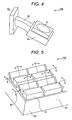
- FIG. 4 is a perspective view showing embodiment 4 of the present invention.
- FIG. 5 is a perspective view showing embodiment 5 of the present invention.
- FIG. 6 is an example of a method of swinging reflectors according to embodiment 5 of the present invention.
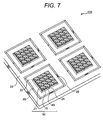
- FIG. 7 is a perspective view showing embodiment 6 of the present invention.
- FIG. 8 is a perspective view showing an example of application of embodiment 1 of the present invention.
- FIG. 9 is a development elevation showing an illuminant unit of the application example shown in FIG. 8.
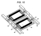
- FIG. 10 is a perspective view showing the backside of a substrate of an illuminant unit shown in FIG. 9.
- Vehicular lighting fixture 100 in FIG. 1 is rectangular, and it is made by using planar seat 20.
- a plurality of illuminants 10 are arranged on movable substrate 21 of seat 20.
- Seat 20 comprises a plurality of movable substrates 21, a plurality of inner frames 22, an outer frame 23, a plurality of beams 24 which link movable substrate 21 to inner frame 22, and a plurality of beams 25 which link inner frame 22 to outer frame 23.
- Two through holes 26 and 27 are arranged in a rectangular shape to outer frame 23 as shown in the figure.
- inner frame 22 and movable substrate 21 are supported to outer frame 23 by beams 24 and 25.
- Beam 24 and beam 25 are arranged in a crosswise direction. That is, they are arranged in an orthogonal direction.
- the axis of the beam by which movable substrate 21 and inner frame 22 are linked and the axis of the beam by which inner frame 22 and outer frame 23 are linked are mutually orthogonal. Movable substrate 21 swings to inner frame 22 by the torsional deformation of these beams, and inner frame 22 and movable substrate 21 swing to outer frame 23.
- a light distribution control device of vehicular lighting fixture comprising a plurality of movable substrates 21 where illuminants 10 are arranged, a plurality of inner frames 22, an outer frame 23, a plurality of beams 24 which link said movable substrates 21 to said inner frames 22, and a plurality of beams 25 which link said inner frames 22 to said outer frame 23, wherein the beams which link said movable substrates 21 to said inner frames 22 and the beams which link said inner frames 22 to said outer frame 23 are mutually orthogonal, and wherein a light distribution pattern is set by deforming under torsion the beams 24 which link said movable substrates 21 to said inner frames 22 and the beams 25 which link said inner frames 22 to said outer frame 23, and swinging each of said movable substrates 21 with respect to said outer frame 23 in the biaxial directions independently.
- illuminants 10 arranged on movable substrate 21 to swing independently to outer frame 23 in the biaxial directions.
- Setting the arbitrary light distribution pattern becomes possible by arbitrarily changing the optical axis of illuminant 10 according to this swing movement.
- the force by which movable substrate 21 is swung to outer frame 23 is obtained on the basis of electrostatic force or electromagnetic force.
- Embodiment 2 of the present invention will be explained by referring to FIG. 2.
- Like numerals designate like members to avoid the duplicated explanation.
- llluminant 10 is mounted on deformable type substrate 31 which provides on seat 20, and deformable type substrate 31 is supported by a plurality of extendable support members 32.
- Deformable type substrate 31 is transformed by expanding or contracting a plurality of extendable support members 32 independently. Setting the arbitrary light distribution pattern becomes possible by changing the optical axis of illuminant 10 mounted on deformable type substrate 31 according to such transformation.
- deformable type substrate 31 is transformed with extendable support members 32 in this embodiment, it is also possible to transform deformable type substrate 31 by using cams or rollers. Moreover, deformable type substrate 31 may be transformed by using non-contact force like electrostatic force and electromagnetic force, etc. as well as in embodiment 1.
- Embodiment 3 of the present invention will be explained with reference to FIG. 3.
- Illuminant 10 is mounted on rigid substrate 33 provided on seat 20, and rigid substrate 33 is supported by a plurality of extendable support members 32.
- Rigid substrate 33 is inclined by expanding or contracting a plurality of extendable support members 32 independently. Setting the arbitrary light distribution pattern becomes possible by changing the optical axis of illuminant 10 mounted on rigid substrate 33 by this inclination.
- rigid substrate 33 is inclined with extendable support members 32 in this embodiment, it is also possible to incline rigid substrate 33 by using cams or rollers. Moreover, rigid substrate 33 may be inclined by using non-contact force like electrostatic force and electromagnetic force, etc.
- Embodiment 4 of the present invention will be explained with reference to FIG. 4.
- Illuminant 10 is mounted on rigid substrate 33 provided on seat 20.
- Rigid substrate 33 is supported by elastic beam 35.
- Rigid substrate 33 is inclined by bending elastic beam 35. Setting the arbitrary light distribution pattern becomes possible by changing the optical axis of illuminant 10 mounted on rigid substrate 33 by this inclination.
- the piezo-electric bimorph, piezo-electric unimorph, thermal deformation or the shape-memory alloy can be used as a means which bends elastic beam 35.
- Embodiment 5 of the present invention will be explained by referring to FIG. 5.
- a plurality of illuminants 10 are arranged on substrate 41 provided on seat 20.
- a plurality of movable reflector 42 are arranged such that they may oppose the luminescence side of illuminant 10.
- Illuminant 10 and movable reflector 42 are arranged on the same substrate in FIG. 5, it is also possible to arrange them on separate substrates.
- the light irradiated from illuminant 10 can be reflected by movable reflector 42 in the desirable direction.
- the optical axis of the reflection light can be arbitrarily changed by swinging movable reflectors 42 in the biaxial directions. As a result, setting the arbitrary light distribution pattern become possible.
- Electrostatic force and electromagnetic force are used as power for swing movable reflector 42. It is also possible to use a piezo-electric element and a magnetostriction element to generate such power.
- movable substrate 21 in embodiment 1 as movable reflector 42 in a method of swinging movable reflector 42.
- movable support member 35 of reflector 43 as shown in FIG. 6.
- Illuminant 1 is mounted on substrate 41.
- reflector 43 is arranged so as to oppose the luminescence side of illuminant 10.
- Reflector 43 is supported by elastic support member 35. It becomes possible to incline reflector 43 by bending this elastic support member 35, and change the direction of the reflection light.
- Embodiment 6 of the present invention is explained by referring to FIG. 7.
- movable substrate 21 is linked to inner frame 22 through beam 24.
- Inner frame 22 is linked to outer frame 23 through beam 25.
- the light irradiated from illuminant 10 is reflected by reflector 43 in the desired direction.
- each unit is made to give the arbitrary light distribution.
- the axis of beam 24 by which unit 50 and inner frame 22 are linked and the axis of beam 25 by which inner frame 22 and outer frame 23 are linked are mutually orthogonal as well as in embodiment 1.
- Unit 50 swings to inner frame 22 by the torsional deformation of these beams 24 and 25, and inner frame 22 and unit 50 swing to outer frame 23.
- each of a plurality of units 50 can swing independently to outer frame 23 in the biaxial directions.
- Setting the arbitrary light distribution pattern becomes possible by arbitrarily changing the optical axis of the light irradiated from illuminant 10 by this swing movement.
- Electrostatic force and electromagnetic force are used as power for swinging unit 50 with respect to outer frame 23. It is also possible to use the piezo-electric element and the magnetostriction element.
- unit 50 and inner frame 22, and inner frame 22 and outer frame 23 are linked by beams 24 and 25, respectively, in this embodiment, a similar effect is achieved even if linking by the rigid body axis through the bearing.
- the light distribution control device shown in FIG. 8 is an application example of the above-mentioned embodiment 6.
- a plurality of illuminant units 60 are linked to outer frame 23 through a plurality of motors 51 provided on seat 20 and a plurality of bearings 52, and they are linked further to inner frame as well as in a previous embodiment.
- Each of a plurality of motors 51 swings independently.
- each of a plurality of illuminant units 60 swings independently to outer frame 23. It is becomes possible accurately to swing illuminant units 60 to the desired position with a step motor.
- FIG. 9 (a), FIG. 9 (b) and FIG. 9 (c) is a development elevation of an illuminant unit 60 shown in FIG. 8.
- FIG. 10 shows the backside of the substrate which is a part of illuminant unit 60.
- Illuminant unit 60 comprises illuminant 10, substrate 61, and seat 20.
- Substrate 61 is provided with moving element 63 and foot 64. Moving element 63 is linked to foot 64 through beam 65.
- Illuminant 10 is arranged on moving element of substrate 61.
- Coil 66 necessary to generate the electromagnetic force for swing moving element 63 and pad 67 for connecting wirings are formed on the backside of substrate 61.
- Feet 64 of substrate 61 are linked to seat 20.
- Permanent magnet 68 necessary to generate the electromagnetic force for swinging moving element 63 of the substrate is arranged on seat 20.
- Capacitive sensor electrode 69 to detect the position where moving element 63 swings is arranged between substrate 61 and seat 20.
Abstract
Description
- The present invention relates to a vehicular lighting fixture for an Adaptive Frontlighing System (AFS), which can control the light distribution.
- For instance, there is Japanese Patent Application Laid-Open No. 2004-71409 as a well-known technology relevant to such a vehicular lighting fixture for the AFS which can control the light distribution.
- In the vehicular lighting fixture for the AFS which can control the light distribution described in Japanese Patent Application Laid-Open No. 2004-71409, a plurality of illuminants with different light distribution is provided, and light distribution is controlled by blinking those illuminants or adjusting the quantity of light of those illuminants.
- However, the following problems exist in the above-mentioned prior art. That is, in the vehicular lighting fixture for the AFS which can control light distribution described in Japanese Patent Application Laid-Open No. 2004-71409, the light distribution is controlled by the blinking or the modulation of light of the illuminants. Therefore, the problem that a lot of illuminants are needed to increase the light distribution patterns to be set, and the entire vehicular lighting fixture becomes large exists.
- An object of the present invention is to provide a vehicular lighting fixture for the AFS which can set a lot of light distribution patterns with few illuminants, that is, without making the entire lighting fixture larger.
- To achieve the above-mentioned object, the present invention adopts the structure in that light from a plurality of illuminants with different light distribution is blinked or modulated, and each of illuminants or each of reflectors which reflects the light irradiated from the illuminants is moved independently. Concretely, the light distribution control device for the AFS shown next is provided.
- A light distribution control device of vehicular lighting fixture comprising a plurality of movable substrates where illuminants are arranged, a plurality of inner frames, an outer frame, a plurality of beams which link said movable substrates to said inner frames, and a plurality of beams which link said inner frames to said outer frame, wherein the beams which link said movable substrates to said inner frames and the beams which link said inner frames to said outer frame are substantially mutually orthogonal, and wherein a light distribution pattern is set by deforming under torsion the beams which link said movable substrates to said inner frames and the beams which link said inner frames to said outer frame, and swinging each of said movable substrates with respect to said outer frame in the biaxial directions independently.
- A vehicular lighting fixture in which a plurality of illuminants are arranged on a deformable type substrate, wherein a light distribution pattern is set by transforming said deformable type substrate.
- A vehicular lighting fixture in which a rigid substrate is supported to an extendable support member, and an illuminant is arranged on said rigid substrate, wherein a light distribution pattern is set by expanding and contracting the extendable support member, and inclining said rigid substrate.
- A vehicular lighting fixture in which a rigid substrate is supported by an elastic beam, and an illuminant is arranged on said rigid substrate, wherein a light distribution pattern is set by bending said elastic beam, and inclining said rigid substrate.
- A vehicular lighting fixture which comprises a plurality of illuminants and a plurality of reflectors, wherein each of said reflectors is arranged as opposed to each of said illuminants so that the arbitrary light distribution can be obtained, and wherein a light distribution pattern is set by swinging each of said reflectors independently.
- A vehicular lighting fixture in which a plurality of units are arranged, which comprises a plurality of illuminants and a plurality of reflectors, wherein each of said units gives the arbitrary light distribution, and wherein a light distribution pattern is set by swinging each of said units independently.
- The present invention can realize a vehicular lighting fixture for the AFS which can set a lot of light distribution patterns without making the entire lighting fixture larger by not only blinking or modulating light from a plurality of illuminants with different light distribution, but also changing the optical axis by moving each of illuminants or each of reflectors which reflects the light irradiated from the illuminants independently.
- The present invention will be understood more fully from the detailed description given hereinafter and from the accompanying drawings of the preferred embodiment of the present invention, which, however, should not be taken to be limitative to the invention, but are for explanation and understanding only. In the drawings:
- FIG. 1 is a perspective view showing embodiment 1 of the present invention.
- FIG. 2 is a perspective view showing embodiment 2 of the present invention.
- FIG. 3 is a perspective view showing embodiment 3 of the present invention.
- FIG. 4 is a perspective view showing embodiment 4 of the present invention.
- FIG. 5 is a perspective view showing embodiment 5 of the present invention.
- FIG. 6 is an example of a method of swinging reflectors according to embodiment 5 of the present invention.
- FIG. 7 is a perspective view showing embodiment 6 of the present invention.
- FIG. 8 is a perspective view showing an example of application of embodiment 1 of the present invention.
- FIG. 9 is a development elevation showing an illuminant unit of the application example shown in FIG. 8.
- FIG. 10 is a perspective view showing the backside of a substrate of an illuminant unit shown in FIG. 9.
- The present invention will be discussed hereinafter in detail in terms of the preferred embodiment of a vehicular travel control system according to the present invention with reference to the accompanying drawings. In the following description, numerous specific details are set forth in order to provide a thorough understanding of the present invention. It will be obvious, however, to those skilled in the art that the present invention may be practiced without these specific details. In other instance, well-known structures are not shown in detail in order to avoid unnecessary obscurity of the present invention. Hereafter, the best mode for carrying out the invention will be explained.
- Embodiment 1 of the present invention will be explained by referring to FIG. 1.
Vehicular lighting fixture 100 in FIG. 1 is rectangular, and it is made by usingplanar seat 20. A plurality ofilluminants 10 are arranged onmovable substrate 21 ofseat 20.Seat 20 comprises a plurality ofmovable substrates 21, a plurality ofinner frames 22, anouter frame 23, a plurality ofbeams 24 which linkmovable substrate 21 toinner frame 22, and a plurality ofbeams 25 which linkinner frame 22 toouter frame 23. Two throughholes outer frame 23 as shown in the figure. As a result,inner frame 22 andmovable substrate 21 are supported toouter frame 23 bybeams Beam 24 andbeam 25 are arranged in a crosswise direction. That is, they are arranged in an orthogonal direction. - The axis of the beam by which
movable substrate 21 andinner frame 22 are linked and the axis of the beam by whichinner frame 22 andouter frame 23 are linked are mutually orthogonal.Movable substrate 21 swings toinner frame 22 by the torsional deformation of these beams, andinner frame 22 andmovable substrate 21 swing toouter frame 23. - Thus, the following structure is achieved. A light distribution control device of vehicular lighting fixture comprising a plurality of
movable substrates 21 whereilluminants 10 are arranged, a plurality ofinner frames 22, anouter frame 23, a plurality ofbeams 24 which link saidmovable substrates 21 to saidinner frames 22, and a plurality ofbeams 25 which link saidinner frames 22 to saidouter frame 23, wherein the beams which link saidmovable substrates 21 to saidinner frames 22 and the beams which link saidinner frames 22 to saidouter frame 23 are mutually orthogonal, and wherein a light distribution pattern is set by deforming under torsion thebeams 24 which link saidmovable substrates 21 to saidinner frames 22 and thebeams 25 which link saidinner frames 22 to saidouter frame 23, and swinging each of saidmovable substrates 21 with respect to saidouter frame 23 in the biaxial directions independently. - As a result, it becomes possible for
illuminants 10 arranged onmovable substrate 21 to swing independently toouter frame 23 in the biaxial directions. Setting the arbitrary light distribution pattern becomes possible by arbitrarily changing the optical axis of illuminant 10 according to this swing movement. The force by whichmovable substrate 21 is swung toouter frame 23 is obtained on the basis of electrostatic force or electromagnetic force. Moreover, it is also possible to use the piezo-electric element and the magnetostriction element. This structure is very simple becausemovable substrate 21 andinner frame 22, andinner frame 22 andouter frame 23 are linked bybeams - Embodiment 2 of the present invention will be explained by referring to FIG. 2. Like numerals designate like members to avoid the duplicated explanation. llluminant 10 is mounted on
deformable type substrate 31 which provides onseat 20, anddeformable type substrate 31 is supported by a plurality ofextendable support members 32.Deformable type substrate 31 is transformed by expanding or contracting a plurality ofextendable support members 32 independently. Setting the arbitrary light distribution pattern becomes possible by changing the optical axis of illuminant 10 mounted ondeformable type substrate 31 according to such transformation. - Although
deformable type substrate 31 is transformed withextendable support members 32 in this embodiment, it is also possible to transformdeformable type substrate 31 by using cams or rollers. Moreover,deformable type substrate 31 may be transformed by using non-contact force like electrostatic force and electromagnetic force, etc. as well as in embodiment 1. - Embodiment 3 of the present invention will be explained with reference to FIG. 3.
Illuminant 10 is mounted onrigid substrate 33 provided onseat 20, andrigid substrate 33 is supported by a plurality ofextendable support members 32.Rigid substrate 33 is inclined by expanding or contracting a plurality ofextendable support members 32 independently. Setting the arbitrary light distribution pattern becomes possible by changing the optical axis ofilluminant 10 mounted onrigid substrate 33 by this inclination. - Although
rigid substrate 33 is inclined withextendable support members 32 in this embodiment, it is also possible to inclinerigid substrate 33 by using cams or rollers. Moreover,rigid substrate 33 may be inclined by using non-contact force like electrostatic force and electromagnetic force, etc. - Embodiment 4 of the present invention will be explained with reference to FIG. 4.
Illuminant 10 is mounted onrigid substrate 33 provided onseat 20.Rigid substrate 33 is supported byelastic beam 35.Rigid substrate 33 is inclined by bendingelastic beam 35. Setting the arbitrary light distribution pattern becomes possible by changing the optical axis ofilluminant 10 mounted onrigid substrate 33 by this inclination. The piezo-electric bimorph, piezo-electric unimorph, thermal deformation or the shape-memory alloy can be used as a means which bendselastic beam 35. - Embodiment 5 of the present invention will be explained by referring to FIG. 5. A plurality of
illuminants 10 are arranged onsubstrate 41 provided onseat 20. Moreover, a plurality ofmovable reflector 42 are arranged such that they may oppose the luminescence side ofilluminant 10. AlthoughIlluminant 10 andmovable reflector 42 are arranged on the same substrate in FIG. 5, it is also possible to arrange them on separate substrates. The light irradiated fromilluminant 10 can be reflected bymovable reflector 42 in the desirable direction. The optical axis of the reflection light can be arbitrarily changed by swingingmovable reflectors 42 in the biaxial directions. As a result, setting the arbitrary light distribution pattern become possible. Electrostatic force and electromagnetic force are used as power for swingmovable reflector 42. It is also possible to use a piezo-electric element and a magnetostriction element to generate such power. - For instance, it is possible to use
movable substrate 21 in embodiment 1 asmovable reflector 42 in a method of swingingmovable reflector 42. Moreover, there is a method of bendingelastic support member 35 ofreflector 43 as shown in FIG. 6. Illuminant 1 is mounted onsubstrate 41.reflector 43 is arranged so as to oppose the luminescence side ofilluminant 10.Reflector 43 is supported byelastic support member 35. It becomes possible to inclinereflector 43 by bending thiselastic support member 35, and change the direction of the reflection light. - Even if
reflector 43 is transformed, a similar effect is achieved although the direction of the reflection light is changed by swingingreflectors 43 in this embodiment. It is also possible to userigid substrate 33 in embodiment 3 asreflector 43. - Embodiment 6 of the present invention is explained by referring to FIG. 7. In a plurality of
units 50, which correspond to the seats, and which comprisesilluminant 10,movable substrate 21 andreflector 43,movable substrate 21 is linked toinner frame 22 throughbeam 24.Inner frame 22 is linked toouter frame 23 throughbeam 25. The light irradiated fromilluminant 10 is reflected byreflector 43 in the desired direction. Moreover, each unit is made to give the arbitrary light distribution. The axis ofbeam 24 by whichunit 50 andinner frame 22 are linked and the axis ofbeam 25 by whichinner frame 22 andouter frame 23 are linked are mutually orthogonal as well as in embodiment 1.Unit 50 swings toinner frame 22 by the torsional deformation of thesebeams inner frame 22 andunit 50 swing toouter frame 23. As a result, each of a plurality ofunits 50 can swing independently toouter frame 23 in the biaxial directions. Setting the arbitrary light distribution pattern becomes possible by arbitrarily changing the optical axis of the light irradiated fromilluminant 10 by this swing movement. Electrostatic force and electromagnetic force are used as power for swingingunit 50 with respect toouter frame 23. It is also possible to use the piezo-electric element and the magnetostriction element. - Although
unit 50 andinner frame 22, andinner frame 22 andouter frame 23 are linked bybeams - The light distribution control device shown in FIG. 8 is an application example of the above-mentioned embodiment 6. A plurality of
illuminant units 60 are linked toouter frame 23 through a plurality ofmotors 51 provided onseat 20 and a plurality ofbearings 52, and they are linked further to inner frame as well as in a previous embodiment. Each of a plurality ofmotors 51 swings independently. Thereby, each of a plurality ofilluminant units 60 swings independently toouter frame 23. It is becomes possible accurately to swingilluminant units 60 to the desired position with a step motor. - Each of FIG. 9 (a), FIG. 9 (b) and FIG. 9 (c) is a development elevation of an
illuminant unit 60 shown in FIG. 8. FIG. 10 shows the backside of the substrate which is a part ofilluminant unit 60.Illuminant unit 60 comprisesilluminant 10,substrate 61, andseat 20.Substrate 61 is provided with movingelement 63 andfoot 64. Movingelement 63 is linked to foot 64 throughbeam 65.Illuminant 10 is arranged on moving element ofsubstrate 61.Coil 66 necessary to generate the electromagnetic force forswing moving element 63 andpad 67 for connecting wirings are formed on the backside ofsubstrate 61.Feet 64 ofsubstrate 61 are linked toseat 20.Permanent magnet 68 necessary to generate the electromagnetic force for swinging movingelement 63 of the substrate is arranged onseat 20.Capacitive sensor electrode 69 to detect the position where movingelement 63 swings is arranged betweensubstrate 61 andseat 20. - When an electric current flows to the coil on the backside of the substrate, the torque whose rolling axis corresponds to the beam of the substrate is generated by the action of the magnetic field generated by
permanent magnet 68 arranged inseat 20 and an electric current which flows to the coil. Thereby, movingelement 63 ofsubstrate 61 swings. Moreover, it becomes possible accurately to swingilluminants 10 on moving element ofsubstrate 61 to the desired position by carrying out the feedback control by usingcapacitive sensor electrode 69.Illuminant 10 on movingelement 63 can swing in the biaxial directions with respect toouter frame 23 by combining the swing of this movingelement 63 and that ofilluminant unit 60 by the motor. Setting the arbitrary light distribution pattern becomes possible by arbitrarily changing the optical axis of the light irradiated from the illuminant by these swing movements. - The components and details of the embodiments described above may be combined to form embodiments adapted to the demands of the respective application. As far as those modifications are readily apparent for an expert skilled in the art, they shall be disclosed implicitly by the description of the above embodiments.
Although the present invention has been illustrated and described with respect to exemplary embodiment thereof, it should be understood by those skilled in the art that the foregoing and various other changes, omission and additions may be made therein and thereto, without departing from the spirit and scope of the present invention. Therefore, the present invention should not be understood as limited to the specific embodiment set out above but to include all possible embodiments which can be embodied within a scope encompassed and equivalent thereof with respect to the feature set out in the appended claims.
Claims (6)
- A light distribution control device of vehicular lighting fixture (100) comprising;
a plurality of movable substrates (21) where illuminants are arranged,
a plurality of inner frames (22),
an outer frame (23),
a plurality of beams (25) which link said movable substrates (21) to said inner frames (22), and
a plurality of beams (25) which link said inner frames (22) to said outer frame (23),
wherein the beams (25) which link said movable substrates (21) to said inner frames (22) and the beams (25) which link said inner frames (22) to said outer frame (23) are mutually orthogonal, and
wherein a light distribution pattern is set by deforming under torsion the beams which link said movable substrates (21) to said inner frames (22) and the beams (25) which link said inner frames (22) to said outer frame (23), and swinging each of said movable substrates (21) with respect to said outer frame (23) in the biaxial directions independently. - A vehicular lighting fixture in which a plurality of illuminants are arranged on deformable type substrate,
wherein a light distribution pattern is set by transforming said deformable type substrate (31). - A vehicular lighting fixture in which a rigid substrate (33) is supported to an extendable support member (32), and an illuminant (10) is arranged on said rigid substrate (33),
wherein a light distribution pattern is set by expanding and contracting the extendable support member (32), and inclining said rigid substrate (33). - A vehicular lighting fixture in which a rigid substrate (33) is supported by an elastic beam (35), and an illuminant is arranged on said rigid substrate (33),
wherein a light distribution pattern is set by bending said elastic beam (35), and inclining said rigid substrate (33). - A vehicular lighting fixture which comprises a plurality of illuminants (10) and a plurality of reflectors (43),
wherein each of said reflectors (43) is arranged as opposed to each of said illuminants (10) so that the arbitrary light distribution can be obtained, and
wherein a light distribution pattern is set by swinging each of said reflectors (43) independently. - A vehicular lighting fixture in which a plurality of units (50) are arranged, which comprises a plurality of illuminants (10) and a plurality of reflectors (43),
wherein each of said units (50) gives the arbitrary light distribution, and
wherein a light distribution pattern is set by swinging each of said units (50) independently.
Applications Claiming Priority (1)
| Application Number | Priority Date | Filing Date | Title |
|---|---|---|---|
| JP2004316031A JP2006127963A (en) | 2004-10-29 | 2004-10-29 | Light distribution control device |
Publications (2)
| Publication Number | Publication Date |
|---|---|
| EP1652726A2 true EP1652726A2 (en) | 2006-05-03 |
| EP1652726A3 EP1652726A3 (en) | 2010-04-14 |
Family
ID=34935250
Family Applications (1)
| Application Number | Title | Priority Date | Filing Date |
|---|---|---|---|
| EP05008316A Withdrawn EP1652726A3 (en) | 2004-10-29 | 2005-04-15 | Light distribution control device |
Country Status (3)
| Country | Link |
|---|---|
| US (1) | US7241038B2 (en) |
| EP (1) | EP1652726A3 (en) |
| JP (1) | JP2006127963A (en) |
Cited By (3)
| Publication number | Priority date | Publication date | Assignee | Title |
|---|---|---|---|---|
| WO2007128762A1 (en) * | 2006-05-05 | 2007-11-15 | Hella Kgaa Hueck & Co. | Headlights for motor vehicles |
| WO2011045358A1 (en) | 2009-10-15 | 2011-04-21 | Hella Kgaa Hueck & Co. | Lighting device for vehicles |
| WO2022175280A3 (en) * | 2021-02-16 | 2022-11-17 | Otto-Von-Guericke-Universität Magdeburg | Image display device and backlighting unit therefor |
Families Citing this family (62)
| Publication number | Priority date | Publication date | Assignee | Title |
|---|---|---|---|---|
| CN101107890A (en) * | 2005-01-25 | 2008-01-16 | 古河电气工业株式会社 | Wiring body for mounting electronic component and electronic component mounting structure |
| US7766524B2 (en) * | 2006-02-08 | 2010-08-03 | Koito Manufacturing Co., Ltd. | Vehicle lamp including optical axis variable light source |
| FR2901347B1 (en) * | 2006-05-22 | 2008-07-18 | Valeo Vision Sa | THERMAL DISSIPATING COMPONENT AND DIODE LIGHTING AND / OR SIGNALING DEVICE EQUIPPED WITH SUCH A COMPONENT |
| JP4697215B2 (en) * | 2007-11-20 | 2011-06-08 | 市光工業株式会社 | Vehicle lighting |
| US8118447B2 (en) | 2007-12-20 | 2012-02-21 | Altair Engineering, Inc. | LED lighting apparatus with swivel connection |
| US7712918B2 (en) | 2007-12-21 | 2010-05-11 | Altair Engineering , Inc. | Light distribution using a light emitting diode assembly |
| CN102007441A (en) * | 2008-04-17 | 2011-04-06 | 皇家飞利浦电子股份有限公司 | High quantum efficiency lighting device with light influencing element |
| US8360599B2 (en) | 2008-05-23 | 2013-01-29 | Ilumisys, Inc. | Electric shock resistant L.E.D. based light |
| US7976196B2 (en) | 2008-07-09 | 2011-07-12 | Altair Engineering, Inc. | Method of forming LED-based light and resulting LED-based light |
| US7946729B2 (en) | 2008-07-31 | 2011-05-24 | Altair Engineering, Inc. | Fluorescent tube replacement having longitudinally oriented LEDs |
| US8674626B2 (en) | 2008-09-02 | 2014-03-18 | Ilumisys, Inc. | LED lamp failure alerting system |
| US8256924B2 (en) | 2008-09-15 | 2012-09-04 | Ilumisys, Inc. | LED-based light having rapidly oscillating LEDs |
| US8901823B2 (en) | 2008-10-24 | 2014-12-02 | Ilumisys, Inc. | Light and light sensor |
| US7938562B2 (en) | 2008-10-24 | 2011-05-10 | Altair Engineering, Inc. | Lighting including integral communication apparatus |
| US8653984B2 (en) | 2008-10-24 | 2014-02-18 | Ilumisys, Inc. | Integration of LED lighting control with emergency notification systems |
| US8444292B2 (en) | 2008-10-24 | 2013-05-21 | Ilumisys, Inc. | End cap substitute for LED-based tube replacement light |
| US8324817B2 (en) | 2008-10-24 | 2012-12-04 | Ilumisys, Inc. | Light and light sensor |
| US8214084B2 (en) | 2008-10-24 | 2012-07-03 | Ilumisys, Inc. | Integration of LED lighting with building controls |
| TWI401788B (en) * | 2008-12-24 | 2013-07-11 | Ind Tech Res Inst | Led packaging module and method |
| US8556452B2 (en) | 2009-01-15 | 2013-10-15 | Ilumisys, Inc. | LED lens |
| US8362710B2 (en) | 2009-01-21 | 2013-01-29 | Ilumisys, Inc. | Direct AC-to-DC converter for passive component minimization and universal operation of LED arrays |
| US8664880B2 (en) | 2009-01-21 | 2014-03-04 | Ilumisys, Inc. | Ballast/line detection circuit for fluorescent replacement lamps |
| US8011813B2 (en) * | 2009-02-03 | 2011-09-06 | Visteon Global Technologies, Inc. | Actuator system for a lighting system |
| US8414155B2 (en) * | 2009-03-18 | 2013-04-09 | Koninklijke Philips Electronics N.V. | LED luminaire |
| US8376582B2 (en) | 2009-03-18 | 2013-02-19 | Koninklijke Philips Electronics N.V. | LED luminaire |
| CN102414506B (en) * | 2009-04-28 | 2014-07-16 | 皇家飞利浦电子股份有限公司 | Lighting unit |
| US8330381B2 (en) | 2009-05-14 | 2012-12-11 | Ilumisys, Inc. | Electronic circuit for DC conversion of fluorescent lighting ballast |
| US8123378B1 (en) | 2009-05-15 | 2012-02-28 | Koninklijke Philips Electronics N.V. | Heatsink for cooling at least one LED |
| US8299695B2 (en) | 2009-06-02 | 2012-10-30 | Ilumisys, Inc. | Screw-in LED bulb comprising a base having outwardly projecting nodes |
| WO2011005579A2 (en) | 2009-06-23 | 2011-01-13 | Altair Engineering, Inc. | Illumination device including leds and a switching power control system |
| US8506127B2 (en) | 2009-12-11 | 2013-08-13 | Koninklijke Philips N.V. | Lens frame with a LED support surface and heat dissipating structure |
| CA2792940A1 (en) | 2010-03-26 | 2011-09-19 | Ilumisys, Inc. | Led light with thermoelectric generator |
| WO2011119907A2 (en) | 2010-03-26 | 2011-09-29 | Altair Engineering, Inc. | Led light tube with dual sided light distribution |
| WO2011119958A1 (en) | 2010-03-26 | 2011-09-29 | Altair Engineering, Inc. | Inside-out led bulb |
| US8454193B2 (en) | 2010-07-08 | 2013-06-04 | Ilumisys, Inc. | Independent modules for LED fluorescent light tube replacement |
| JP2013531350A (en) | 2010-07-12 | 2013-08-01 | イルミシス,インコーポレイテッド | Circuit board mount for LED arc tube |
| US8523394B2 (en) | 2010-10-29 | 2013-09-03 | Ilumisys, Inc. | Mechanisms for reducing risk of shock during installation of light tube |
| US8870415B2 (en) | 2010-12-09 | 2014-10-28 | Ilumisys, Inc. | LED fluorescent tube replacement light with reduced shock hazard |
| US8810902B2 (en) * | 2010-12-29 | 2014-08-19 | Asml Netherlands B.V. | Multi-pass optical apparatus |
| US20120293995A1 (en) * | 2011-05-19 | 2012-11-22 | Wybron, Inc. | Led light assembly and method for construction thereof |
| US9072171B2 (en) | 2011-08-24 | 2015-06-30 | Ilumisys, Inc. | Circuit board mount for LED light |
| JP2013054959A (en) * | 2011-09-05 | 2013-03-21 | Ichikoh Ind Ltd | Vehicle lighting device |
| WO2013131002A1 (en) | 2012-03-02 | 2013-09-06 | Ilumisys, Inc. | Electrical connector header for an led-based light |
| US9115880B2 (en) * | 2012-05-04 | 2015-08-25 | Abl Ip Holding, Llc | Lighting system reconfigurable by gestural control |
| WO2014008463A1 (en) | 2012-07-06 | 2014-01-09 | Ilumisys, Inc. | Power supply assembly for led-based light tube |
| US9271367B2 (en) | 2012-07-09 | 2016-02-23 | Ilumisys, Inc. | System and method for controlling operation of an LED-based light |
| CN103978924A (en) * | 2013-02-07 | 2014-08-13 | 李育全 | Auxiliary guiding system for driving direction |
| US9285084B2 (en) | 2013-03-14 | 2016-03-15 | Ilumisys, Inc. | Diffusers for LED-based lights |
| KR101474272B1 (en) * | 2013-08-14 | 2014-12-18 | 한국항공우주연구원 | System for testing star tracker of satellite |
| US9267650B2 (en) | 2013-10-09 | 2016-02-23 | Ilumisys, Inc. | Lens for an LED-based light |
| USD736990S1 (en) * | 2013-12-30 | 2015-08-18 | Hangzhou Hpwinner Opto Corporation | LED lens |
| USD736989S1 (en) * | 2013-12-30 | 2015-08-18 | Hangzhou Hpwinner Opto Corporation | LED lens |
| USD736988S1 (en) * | 2013-12-30 | 2015-08-18 | Hangzhou Hpwinner Opto Corporation | LED lens |
| KR20160111975A (en) | 2014-01-22 | 2016-09-27 | 일루미시스, 인크. | Led-based light with addressed leds |
| JP6236745B2 (en) * | 2014-02-17 | 2017-11-29 | スタンレー電気株式会社 | Vehicle lighting |
| US9510400B2 (en) | 2014-05-13 | 2016-11-29 | Ilumisys, Inc. | User input systems for an LED-based light |
| USD736992S1 (en) * | 2014-06-26 | 2015-08-18 | Hangzhou Hpwinner Opto Corporation | LED lens |
| USD736991S1 (en) * | 2014-06-26 | 2015-08-18 | Hangzhou Hpwinner Opto Corporation | LED lens |
| USD774006S1 (en) * | 2014-08-27 | 2016-12-13 | Mitsubishi Electric Corporation | Light source module |
| DE102015206801A1 (en) * | 2015-04-15 | 2016-10-20 | Osram Gmbh | Lighting device with LEDs |
| US10161568B2 (en) | 2015-06-01 | 2018-12-25 | Ilumisys, Inc. | LED-based light with canted outer walls |
| US10585215B2 (en) | 2017-06-29 | 2020-03-10 | Cymer, Llc | Reducing optical damage on an optical element |
Citations (4)
| Publication number | Priority date | Publication date | Assignee | Title |
|---|---|---|---|---|
| EP0364806A2 (en) * | 1988-10-21 | 1990-04-25 | TEMIC TELEFUNKEN microelectronic GmbH | Surface light-emitting device |
| US5938319A (en) * | 1995-08-16 | 1999-08-17 | Robert Bosch Gmbh | Vehicle headlight with adjusting means for different traffic conditions |
| US20040012460A1 (en) * | 2002-07-16 | 2004-01-22 | Korea Advanced Institute Of Science And Technology | Electromagnetically actuated micromirror actuator and fabrication method thereof |
| US20040240217A1 (en) * | 2003-05-30 | 2004-12-02 | Guide Corporation | AFS for LED headlamp |
Family Cites Families (13)
| Publication number | Priority date | Publication date | Assignee | Title |
|---|---|---|---|---|
| US1335832A (en) * | 1917-12-31 | 1920-04-06 | Harvey Walter James | Light-controlling device |
| US1696055A (en) * | 1927-01-31 | 1928-12-18 | Porter Benjamin | Glareless headlight |
| US4423471A (en) * | 1982-09-15 | 1983-12-27 | Mycro-Group Company | Mobile lighting fixture, method and boom |
| US5481441A (en) * | 1993-09-20 | 1996-01-02 | Stevens; Daniel W. | Adjustable light bar apparatus |
| US5519596A (en) * | 1995-05-16 | 1996-05-21 | Hewlett-Packard Company | Moldable nesting frame for light emitting diode array |
| DE19909399C1 (en) * | 1999-03-04 | 2001-01-04 | Osram Opto Semiconductors Gmbh | Flexible LED multiple module, especially for a light housing of a motor vehicle |
| JP2001001832A (en) * | 1999-06-15 | 2001-01-09 | Nissan Motor Co Ltd | Lighting system for vehicle |
| JP2002324403A (en) * | 2001-04-25 | 2002-11-08 | Dainippon Screen Mfg Co Ltd | Field of view lighting system |
| FR2826709B1 (en) * | 2001-06-29 | 2004-02-13 | Valeo Vision | VARIABLE ORIENTATION LIGHTING DEVICE |
| WO2003016782A1 (en) * | 2001-08-09 | 2003-02-27 | Matsushita Electric Industrial Co., Ltd. | Led illuminator and card type led illuminating light source |
| JP4089866B2 (en) * | 2001-10-12 | 2008-05-28 | スタンレー電気株式会社 | Light projecting unit and LED vehicle illumination lamp comprising the light projecting unit |
| US6666563B2 (en) * | 2002-04-12 | 2003-12-23 | Dahvid N. Brown | Illumination device |
| JP2004071409A (en) * | 2002-08-07 | 2004-03-04 | Denso Corp | Vehicular lighting fixture and light distribution control method for same |
-
2004
- 2004-10-29 JP JP2004316031A patent/JP2006127963A/en active Pending
-
2005
- 2005-04-15 US US11/106,450 patent/US7241038B2/en not_active Expired - Fee Related
- 2005-04-15 EP EP05008316A patent/EP1652726A3/en not_active Withdrawn
Patent Citations (4)
| Publication number | Priority date | Publication date | Assignee | Title |
|---|---|---|---|---|
| EP0364806A2 (en) * | 1988-10-21 | 1990-04-25 | TEMIC TELEFUNKEN microelectronic GmbH | Surface light-emitting device |
| US5938319A (en) * | 1995-08-16 | 1999-08-17 | Robert Bosch Gmbh | Vehicle headlight with adjusting means for different traffic conditions |
| US20040012460A1 (en) * | 2002-07-16 | 2004-01-22 | Korea Advanced Institute Of Science And Technology | Electromagnetically actuated micromirror actuator and fabrication method thereof |
| US20040240217A1 (en) * | 2003-05-30 | 2004-12-02 | Guide Corporation | AFS for LED headlamp |
Cited By (3)
| Publication number | Priority date | Publication date | Assignee | Title |
|---|---|---|---|---|
| WO2007128762A1 (en) * | 2006-05-05 | 2007-11-15 | Hella Kgaa Hueck & Co. | Headlights for motor vehicles |
| WO2011045358A1 (en) | 2009-10-15 | 2011-04-21 | Hella Kgaa Hueck & Co. | Lighting device for vehicles |
| WO2022175280A3 (en) * | 2021-02-16 | 2022-11-17 | Otto-Von-Guericke-Universität Magdeburg | Image display device and backlighting unit therefor |
Also Published As
| Publication number | Publication date |
|---|---|
| JP2006127963A (en) | 2006-05-18 |
| US20060092657A1 (en) | 2006-05-04 |
| EP1652726A3 (en) | 2010-04-14 |
| US7241038B2 (en) | 2007-07-10 |
Similar Documents
| Publication | Publication Date | Title |
|---|---|---|
| US7241038B2 (en) | Light distribution control device | |
| US7431364B2 (en) | Microgripper device for a micro-mechanism | |
| CN103528007B (en) | More headlamps adjust linkage | |
| US6465929B1 (en) | Microelectromechanical system actuator for extended linear motion | |
| CN107464586B (en) | Three-degree-of-freedom large-stroke micro-positioning platform with decoupled driving force | |
| EP1058143A3 (en) | A micro-mirror device and a method for producing a micro-mirror device | |
| US5505521A (en) | Sprung seat frame | |
| JP2000195788A (en) | Optical system, projection illumination unit used especially for microlithography | |
| WO2015086088A1 (en) | Sma valve for controlling pressurized air supply to an air cell in a vehicle seat | |
| WO2005085125A1 (en) | Micro actuator and device having micro actuator | |
| WO2006022967A1 (en) | Mems mirror with amplification of mirror rotation angle | |
| US6657764B1 (en) | Very large angle integrated optical scanner made with an array of piezoelectric monomorphs | |
| KR100996521B1 (en) | Piezoelectric electromechanical drive unit | |
| US20030173866A1 (en) | Microelectromechanical system & method for producing displacement multiplication | |
| KR20160119101A (en) | Method for displacing at least one optical component | |
| JP2002287045A (en) | Parallel flat plate type micro electrostatic actuator, micro optical path switch, micro mechanical switch, and their driving method | |
| RU2699209C1 (en) | Walking insectomorphous mobile microrobot | |
| JP2002277755A (en) | Reflection mirror device | |
| JP3772005B2 (en) | Moving device and scanning probe microscope having the moving device | |
| JP2003075738A (en) | Optical switch | |
| EP4280430A1 (en) | Drive system, control method, and control program | |
| CN210865635U (en) | Two-degree-of-freedom compliant precision positioning platform capable of realizing motion decoupling | |
| EP3184366B1 (en) | Moveable rear view mirror comprising active material | |
| EP4280431A1 (en) | Drive system, control method, and control program | |
| EP4280432A1 (en) | Manufacturing device, control method, and control program |
Legal Events
| Date | Code | Title | Description |
|---|---|---|---|
| PUAI | Public reference made under article 153(3) epc to a published international application that has entered the european phase |
Free format text: ORIGINAL CODE: 0009012 |
|
| AK | Designated contracting states |
Kind code of ref document: A2 Designated state(s): AT BE BG CH CY CZ DE DK EE ES FI FR GB GR HU IE IS IT LI LT LU MC NL PL PT RO SE SI SK TR |
|
| AX | Request for extension of the european patent |
Extension state: AL BA HR LV MK YU |
|
| 17P | Request for examination filed |
Effective date: 20090618 |
|
| PUAL | Search report despatched |
Free format text: ORIGINAL CODE: 0009013 |
|
| AK | Designated contracting states |
Kind code of ref document: A3 Designated state(s): AT BE BG CH CY CZ DE DK EE ES FI FR GB GR HU IE IS IT LI LT LU MC NL PL PT RO SE SI SK TR |
|
| AX | Request for extension of the european patent |
Extension state: AL BA HR LV MK YU |
|
| STAA | Information on the status of an ep patent application or granted ep patent |
Free format text: STATUS: THE APPLICATION HAS BEEN WITHDRAWN |
|
| 18W | Application withdrawn |
Effective date: 20101025 |
|
| AKX | Designation fees paid |
Designated state(s): DE FR |