EP1645406A1 - Machine for making paper cushioning products - Google Patents
Machine for making paper cushioning products Download PDFInfo
- Publication number
- EP1645406A1 EP1645406A1 EP05003407A EP05003407A EP1645406A1 EP 1645406 A1 EP1645406 A1 EP 1645406A1 EP 05003407 A EP05003407 A EP 05003407A EP 05003407 A EP05003407 A EP 05003407A EP 1645406 A1 EP1645406 A1 EP 1645406A1
- Authority
- EP
- European Patent Office
- Prior art keywords
- shaft
- paper web
- rollers
- machine according
- drive
- Prior art date
- Legal status (The legal status is an assumption and is not a legal conclusion. Google has not performed a legal analysis and makes no representation as to the accuracy of the status listed.)
- Withdrawn
Links
Images

Classifications
-
- B—PERFORMING OPERATIONS; TRANSPORTING
- B31—MAKING ARTICLES OF PAPER, CARDBOARD OR MATERIAL WORKED IN A MANNER ANALOGOUS TO PAPER; WORKING PAPER, CARDBOARD OR MATERIAL WORKED IN A MANNER ANALOGOUS TO PAPER
- B31D—MAKING ARTICLES OF PAPER, CARDBOARD OR MATERIAL WORKED IN A MANNER ANALOGOUS TO PAPER, NOT PROVIDED FOR IN SUBCLASSES B31B OR B31C
- B31D5/00—Multiple-step processes for making three-dimensional articles ; Making three-dimensional articles
- B31D5/0039—Multiple-step processes for making three-dimensional articles ; Making three-dimensional articles for making dunnage or cushion pads
- B31D5/0043—Multiple-step processes for making three-dimensional articles ; Making three-dimensional articles for making dunnage or cushion pads including crumpling flat material
- B31D5/0047—Multiple-step processes for making three-dimensional articles ; Making three-dimensional articles for making dunnage or cushion pads including crumpling flat material involving toothed wheels
-
- B—PERFORMING OPERATIONS; TRANSPORTING
- B31—MAKING ARTICLES OF PAPER, CARDBOARD OR MATERIAL WORKED IN A MANNER ANALOGOUS TO PAPER; WORKING PAPER, CARDBOARD OR MATERIAL WORKED IN A MANNER ANALOGOUS TO PAPER
- B31D—MAKING ARTICLES OF PAPER, CARDBOARD OR MATERIAL WORKED IN A MANNER ANALOGOUS TO PAPER, NOT PROVIDED FOR IN SUBCLASSES B31B OR B31C
- B31D2205/00—Multiple-step processes for making three-dimensional articles
- B31D2205/0005—Multiple-step processes for making three-dimensional articles for making dunnage or cushion pads
- B31D2205/0011—Multiple-step processes for making three-dimensional articles for making dunnage or cushion pads including particular additional operations
- B31D2205/0017—Providing stock material in a particular form
- B31D2205/0023—Providing stock material in a particular form as web from a roll
-
- B—PERFORMING OPERATIONS; TRANSPORTING
- B31—MAKING ARTICLES OF PAPER, CARDBOARD OR MATERIAL WORKED IN A MANNER ANALOGOUS TO PAPER; WORKING PAPER, CARDBOARD OR MATERIAL WORKED IN A MANNER ANALOGOUS TO PAPER
- B31D—MAKING ARTICLES OF PAPER, CARDBOARD OR MATERIAL WORKED IN A MANNER ANALOGOUS TO PAPER, NOT PROVIDED FOR IN SUBCLASSES B31B OR B31C
- B31D2205/00—Multiple-step processes for making three-dimensional articles
- B31D2205/0005—Multiple-step processes for making three-dimensional articles for making dunnage or cushion pads
- B31D2205/0076—Multiple-step processes for making three-dimensional articles for making dunnage or cushion pads involving particular machinery details
- B31D2205/0082—General layout of the machinery or relative arrangement of its subunits
Definitions
- the present invention relates to a machine for producing paper pads according to the preamble of claim 1.
- a machine is known from WO-A-00/07808.
- an additional unit can be connected to the shaft led out of the housing, which also has to be driven.
- Such an accessory may be an additional drive wheel, a conveyor belt, a winding device or the like.
- the machine for the production of paper pads is universally usable, as to the led out of the housing shaft only when needed, the corresponding additional units. must be connected. If an auxiliary drive is not required, the shaft can be protected by means of a cover, for example. At the same time it is not necessary for an auxiliary drive additional Aggregates other auxiliary drives must be provided. Rather, it is inventively possible to drive both the machine for the production of paper pads as well as any auxiliary equipment with only a single electric drive.
- At least one, in particular against the force of a spring pivotally mounted drive wheel is rotatably connected to the shaft.
- This drive wheel is thus set in rotation by the shaft driven by the drive and is at the same time mounted pivotably.
- At least one deflection roller is provided for the paper web, whose shaft is movably mounted in oblong holes against the force of a spring.
- a storage of pulleys in oblong holes is already known from the aforementioned prior art, but burden in this state In the art, the pulleys, which can also have a guiding function, the paper web solely due to its own weight.
- a spring is additionally provided, which biases the deflection roller in the oblong holes. In this way, the machine can also smoothly and quietly start when a very heavy supply roll is provided.
- At least two parallel deflection rollers can be provided for the paper web, whose shafts are each movably mounted in oblong holes against the force of a first and a second spring, wherein the spring forces of the first and the second spring are oriented substantially in opposite directions.
- the paper web can be guided in a serpentine shape around the adjacent deflection rollers, whereby a multiplication of the damping path takes place through the oppositely oriented springs.
- the machine has a guide channel through which the partially or already completely transformed into a paper pad paper web is guided.
- a pair of meshing toothed rollers is provided, wherein the width of the pair of rollers or pairs of rollers is at least 50% of the smallest clear width of the guide channel.
- the smallest clear width refers to the dimension of the guide channel which is parallel to the axis of rotation of the rollers.
- a further advantageous embodiment may be rotatably connected to the shaft for the auxiliary drive arranged outside the housing conveyor belt.
- a conveyor belt may serve to convey individual paper pads after manufacture to a work station or storage bin. It is also possible to rotatably connect with the shaft a winding device arranged outside the housing or another auxiliary device.
- the present invention is particularly suitable for heavy stock rolls, high processing speeds, and low tear strength papers.
- the pad to be produced with the machine according to the invention can be a single pad or even an endless pad.
- the rolls or pairs of rolls used for the transport of the paper web preferably have a width of about 40 mm to about 200 mm.
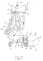
- Fig. 1 shows a machine for the production of pad-like material or of paper pads, wherein the machine is divided into a frame 1 and a housing 2.
- the housing 2 is provided with a motor 3 drive to pull a paper web 8 through a forming device 22, 22 'and 22 "and to form a pad from the paper web.
- the frame 1 consists essentially of a frame 4, two side panels 5 formed as end shields, which are mounted free-standing on the frame, and a support 6, which is preferably pivotally attached to the frame 4.
- the attachment of the carrier 6 to the frame 4 is preferably carried out with the aid of a lockable bracket 6 ', so that the carrier 6 can be pivoted about a horizontal cross member of the frame 4.
- On the frame 1 a plurality of wheels 7 are provided to move the machine.
- an arrangement for feeding the paper web 8 is mounted.
- the arrangement comprises a shaft 11 for a supply roll 12 with a paper web consisting of two paper layers. Further, mutually parallel guide rollers 13, 17 and 18 are provided, wherein the guide rollers 17 and 18 form a separator 14 to separate the paper layers.
- the shaft 11 of the supply roll 12 is on the side parts 5 of the frame stored.
- the deflection rollers 13, 17 and 18 are each mounted with their shafts in a slot 16 which is arranged vertically in each side member 5 substantially.
- the separating device 14 comprises the deflection roller 17, which is in contact with the paper web 8 and serves to lift and deflect a paper layer, and the second deflection roller 18, which is intended to deflect the second paper layer.
- a further roller 19 is mounted in bores, which are formed in the side parts 5.
- the first deflection roller 17 rests on the roller 19 with the paper web 8 interposed therebetween.
- FIG. 1 also shows the waves of the guide rollers 13, 17 and 18 within the slots against the force of springs 23 are movable.
- a brake band 20 On the outer circumference of the supply roll 12 is a brake band 20, which consists of spring steel.
- a funnel-shaped shaft 22 is provided which has on the narrow side a converging section with curved wall sections.
- a supply roll 12 is inserted into the frame 1.
- the bearing plates 5 are free-standing attached to the frame 1, so that the guide rollers 13, 17 and 18 and the rollers 19 are freely accessible.
- the provided with the shaft 11 supply roll 12 is rolled as shown in Fig. 1 on a provided for the storage of the shaft 11 recess. In this position, the supply roll 12 comes into contact with the brake band 20, so that unintentional unwinding of the paper web is prevented.
- the paper web 8 is subsequently introduced via the deflection roller 13 between the deflection roller 17 and the roller 19.
- the two paper layers of the paper web 8 are at the pulleys 17 and 18 separated. Subsequently, the ends of the paper layers are introduced into the shaft 22.
- the forming devices 22 'and 22 " which effect a lateral curling of the paper web in cooperation with the shaft 22, serve to deform the paper web.
- a shaft 50 is provided within the housing 2, which is rotatably mounted on two bearings 51 and 52 and can be driven by the motor 3.
- two toothed rollers 54 and 56 are rigidly fixed, which mesh with corresponding toothed rollers 58 and 60, wherein the rollers 58 and 60 are in turn mounted on a common shaft mounted on respective bearings and arranged parallel to the shaft 50.
- the rollers 54 and 58 form a first pair of rollers and the rollers 56 and 60 form a second pair of rollers. Both pairs of rollers are arranged in the region of a guide channel 62, through which the paper web preformed by the shaping device is pulled.
- width of the rollers 54 and 56 taken together is greater than 50% of the smallest clear width of the guide channel in the direction of the axis of the shaft 50.
- the roller pairs 54, 58 and 56 , 60 grasp the paper web within the guide channel 62 over a large area, so that there is no tearing of the paper web and this even if a very heavy supply roll 12 is used.
- Fig. 2 also shows that the shaft 50 is led out laterally from the housing 2, wherein outside of the housing 2 on the shaft 50, a gear 64 is fixed, which drives a belt or chain drive 66, which drives two juxtaposed drive wheels 68th (Fig. 1) is used.
- the drive wheels 68 are rotatably mounted at the end of an arm 70 which is pivotally mounted on the housing 2 via a pivot bearing 72.
- a spring 74 is provided between the frame 4 and the pivot arm 70, which biases the drive wheels 68, which serve as an auxiliary drive for the supply roll 12 in the direction of the supply roll 12.
- the shaft 50 is driven by the drive motor 3, which drives not only the roller pairs 54 to 60 but also the outside of the housing 2 provided gear 64, which serves as an auxiliary drive for the drive wheels 68.
- the guide roller 13 lies with its own weight on the paper web 8 in order to keep the paper web under tension.
- the pulleys 17 and 18 are also with their own weight on the paper web, on the one hand to stretch the individual paper layers and on the other hand to ensure a uniform supply of paper layers.
- the guide rollers 13, 17 and 18 are raised in the slots against the force of the springs 23, so that even with a heavy supply roll 12 a trouble-free starting is possible. Since, during operation of the motor 3, both the roller pairs 54 to 60 as well as the drive wheels 68 are rotated As a whole, the tensile force exerted on the paper web is reduced, which protects the paper.
- FIG 3 shows an alternative embodiment of an arrangement of three parallel deflection rollers 13, 13 'and 13 ", which are each guided with their shafts in parallel oblong holes, the shafts of the deflection rollers being in each case counter to the force of a spring 23a, 23b and 23c Holes are movably mounted, wherein the spring force of the central spring 23b is oriented substantially in opposite directions to the spring force of the springs 23a and 23c Machine can be moved within the slots against the force of the springs.
- a further supply roll 45 can be inserted with such a paper web into lateral bearing plates 42 and, in addition to the paper web 8, pulled through the forming device and guided through the guide channel with the aid of the pairs of rolls, to connect the extra paper layer to the other paper layers.
Abstract
Description
Die vorliegende Erfindung betrifft eine Maschine zur Herstellung von Papier-Polstern nach dem Oberbegriff des Anspruchs 1. Eine solche Maschine ist aus der WO-A-00/07808 bekannt.The present invention relates to a machine for producing paper pads according to the preamble of claim 1. Such a machine is known from WO-A-00/07808.
Es ist die Aufgabe der Erfindung, eine Maschine der eingangs genannten Art so zu verbessern, dass diese bei kostengünstiger Herstellung für verschiedene Anwendungen universell verwendbar ist.It is the object of the invention to improve a machine of the type mentioned above so that it can be used universally at low cost for various applications.
Die Lösung dieser Aufgabe erfolgt durch die Merkmale des Anspruchs 1 und insbesondere dadurch, dass aus dem Gehäuse eine mit dem Antrieb verbundene Welle für einen Hilfsantrieb herausgeführt ist.The solution of this object is achieved by the features of claim 1 and in particular by the fact that out of the housing connected to the drive shaft is led out for an auxiliary drive.
Erfindungsgemäß kann an die aus dem Gehäuse herausgeführte Welle ein Zusatzaggregat angeschlossen werden, das ebenfalls angetrieben werden muss. Ein solches Zusatzaggregat kann ein zusätzliches Antriebsrad, ein Förderband, eine Wickelvorrichtung oder dergleichen sein.According to the invention, an additional unit can be connected to the shaft led out of the housing, which also has to be driven. Such an accessory may be an additional drive wheel, a conveyor belt, a winding device or the like.
Durch die erfindungsgemäße Lösung ist die Maschine zur Herstellung von Papier-Polstern universell verwendbar, da an die aus dem Gehäuse herausgeführte Welle nur bei Bedarf die entsprechenden Zusatzaggregate. angeschlossen werden müssen. Falls ein Hilfsantrieb nicht benötigt wird, kann die Welle beispielsweise mit Hilfe einer Abdeckung geschützt werden. Gleichzeitig ist es nicht erforderlich, dass für einen Hilfsantrieb zusätzlicher Aggregate weitere Hilfsantriebe vorgesehen werden müssen. Vielmehr ist es erfindungsgemäß möglich, mit nur einem einzigen elektrischen Antrieb sowohl die Maschine zur Herstellung von Papier-Polstern wie auch etwaiger Hilfsaggregate anzutreiben.By the solution according to the invention, the machine for the production of paper pads is universally usable, as to the led out of the housing shaft only when needed, the corresponding additional units. must be connected. If an auxiliary drive is not required, the shaft can be protected by means of a cover, for example. At the same time it is not necessary for an auxiliary drive additional Aggregates other auxiliary drives must be provided. Rather, it is inventively possible to drive both the machine for the production of paper pads as well as any auxiliary equipment with only a single electric drive.
Vorteilhafte Ausführungsformen der Erfindung sind in der Beschreibung, den Ansprüchen und den Zeichnungen beschrieben.Advantageous embodiments of the invention are described in the description, the claims and the drawings.
Nach einer ersten vorteilhaften Ausführungsform ist mit der Welle zumindest ein, insbesondere gegen die Kraft einer Feder verschwenkbar gelagertes Antriebsrad drehbar verbunden. Dieses Antriebsrad wird also durch die vom Antrieb angetriebene Welle in Drehung versetzt und ist gleichzeitig selbst verschwenkbar gelagert. Auf diese Weise ist es möglich, mit Hilfe des Antriebsrads eine Vorratsrolle, von der die Papierbahn abgewickelt wird, zusätzlich anzutreiben, was insbesondere bei schweren Vorratsrollen vorteilhaft ist.According to a first advantageous embodiment, at least one, in particular against the force of a spring pivotally mounted drive wheel is rotatably connected to the shaft. This drive wheel is thus set in rotation by the shaft driven by the drive and is at the same time mounted pivotably. In this way it is possible, with the help of the drive wheel, a supply roll from which the paper web is unwound, additionally driving, which is particularly advantageous for heavy supply rolls.
Besonders vorteilhaft ist es, wenn ein einziger Elektromotor vorgesehen ist, der den Antrieb, die Welle und vorzugsweise auch eine Schneidvorrichtung zum Abtrennen einzelner Papier-Polster antreibt. Auf diese Weise kann die Maschine sehr kostengünstig hergestellt werden, wobei sich gleichzeitig eine kompakte Bauweise ergibt.It is particularly advantageous if a single electric motor is provided which drives the drive, the shaft and preferably also a cutting device for separating individual paper pads. In this way, the machine can be produced very inexpensively, while resulting in a compact design.
Nach einer weiteren vorteilhaften Ausführungsform der Erfindung ist für die Papierbahn zumindest eine Umlenkrolle vorgesehen, deren Welle in Langlöchern gegen die Kraft einer Feder beweglich gelagert ist. Eine Lagerung der Umlenkrollen in Langlöchern ist zwar aus dem eingangs genannten Stand der Technik bereits bekannt, jedoch belasten bei diesem Stand der Technik die Umlenkrollen, die auch eine Führungsfunktion besitzen können, die Papierbahn ausschließlich aufgrund ihres Eigengewichtes. Erfindungsgemäß ist jedoch zusätzlich eine Feder vorgesehen, welche die Umlenkrolle in den Langlöchern vorspannt. Auf diese Weise lässt sich die Maschine auch dann ruckfrei und leise anfahren, wenn eine sehr schwere Vorratsrolle vorgesehen ist.According to a further advantageous embodiment of the invention, at least one deflection roller is provided for the paper web, whose shaft is movably mounted in oblong holes against the force of a spring. Although a storage of pulleys in oblong holes is already known from the aforementioned prior art, but burden in this state In the art, the pulleys, which can also have a guiding function, the paper web solely due to its own weight. According to the invention, however, a spring is additionally provided, which biases the deflection roller in the oblong holes. In this way, the machine can also smoothly and quietly start when a very heavy supply roll is provided.
Nach einer weiteren vorteilhaften Ausführungsform können zumindest zwei parallele Umlenkrollen für die Papierbahn vorgesehen sein, deren Wellen jeweils in Langlöchern gegen die Kraft einer ersten und einer zweiten Feder beweglich gelagert sind, wobei die Federkräfte der ersten und der zweiten Feder im Wesentlichen gegensinnig orientiert sind. Bei dieser Ausführungsform kann die Papierbahn schlangenlinienförmig um die benachbarten Umlenkrollen geführt werden, wobei durch die gegensinnig orientierten Federn eine Vervielfachung des Dämpfungsweges erfolgt.According to a further advantageous embodiment, at least two parallel deflection rollers can be provided for the paper web, whose shafts are each movably mounted in oblong holes against the force of a first and a second spring, wherein the spring forces of the first and the second spring are oriented substantially in opposite directions. In this embodiment, the paper web can be guided in a serpentine shape around the adjacent deflection rollers, whereby a multiplication of the damping path takes place through the oppositely oriented springs.
Nach einer weiteren vorteilhaften Ausführungsform weist die Maschine einen Führungskanal auf, durch den die teilweise oder bereits vollständig zu einem Papier-Polster umgeformte Papierbahn geführt wird. In der Nähe des Führungskanals oder auch in dem Führungskanal selbst ist ein Paar von miteinander kämmenden Zahnwalzen vorgesehen, wobei die Breite des Walzenpaars oder der Walzenpaare mindestens 50 % der geringsten lichten Weite des Führungskanals beträgt. Hierbei bezieht sich die geringste lichte Weite auf diejenige Dimension des Führungskanals, die parallel zur Drehachse der Walzen verläuft.According to a further advantageous embodiment, the machine has a guide channel through which the partially or already completely transformed into a paper pad paper web is guided. In the vicinity of the guide channel or in the guide channel itself, a pair of meshing toothed rollers is provided, wherein the width of the pair of rollers or pairs of rollers is at least 50% of the smallest clear width of the guide channel. Here, the smallest clear width refers to the dimension of the guide channel which is parallel to the axis of rotation of the rollers.
Bei dieser Ausführungsform ergibt sich wiederum der Vorteil, dass bei sehr schweren Vorratsrollen aufgrund der vergleichsweise breiten Walzen die Papierbahn durch die Walzen gegriffen und durch die Umformeinrichtung gezogen werden kann, ohne dass die Papierbahn im Bereich der Walzen einreißt, was insbesondere beim Anfahren der Maschine problematisch sein kann.In this embodiment, in turn, there is the advantage that with very heavy supply rolls due to the comparatively wide rolls the paper web can be gripped by the rollers and pulled through the forming device without the paper web tearing in the region of the rollers, which can be problematic, in particular, when starting the machine.
Nach einer weiteren vorteilhaften Ausführungsform kann mit der Welle für den Hilfsantrieb ein außerhalb des Gehäuses angeordnetes Förderband drehbar verbunden sein. Ein solches Förderband kann dazu dienen, einzelne Papier-Polster nach der Herstellung zu einem Arbeitsplatz oder Vorratsbehälter zu fördern. Auch ist es möglich, mit der Welle eine außerhalb des Gehäuses angeordnete Wickeleinrichtung oder ein anderes Hilfsaggregat drehbar zu verbinden.According to a further advantageous embodiment may be rotatably connected to the shaft for the auxiliary drive arranged outside the housing conveyor belt. Such a conveyor belt may serve to convey individual paper pads after manufacture to a work station or storage bin. It is also possible to rotatably connect with the shaft a winding device arranged outside the housing or another auxiliary device.
Die vorliegende Erfindung eignet sich besonders für schwere Vorratsrollen, hohe Verarbeitungsgeschwindigkeiten und Papiere mit niedriger Reißfestigkeit. Die mit der erfindungsgemäßen Maschine herzustellenden Polster können Einzelpolster oder aber auch Endlospolster sein. Die für den Transport der Papierbahn verwendeten Walzen bzw. Walzenpaare besitzen bevorzugt eine Breite von etwa 40 mm bis etwa 200 mm.The present invention is particularly suitable for heavy stock rolls, high processing speeds, and low tear strength papers. The pad to be produced with the machine according to the invention can be a single pad or even an endless pad. The rolls or pairs of rolls used for the transport of the paper web preferably have a width of about 40 mm to about 200 mm.
Nachfolgend wird die vorliegende Erfindung rein beispielhaft anhand vorteilhafter Ausführungsformen und unter Bezugnahme auf die beigefügten Zeichnungen beschrieben. Es zeigen:
- Fig. 1
- eine schematische Darstellung einer Maschine zur Herstellung von Papier-Polstern;
- Fig. 2
- einen Schnitt durch die Maschine von Fig. 1 entlang der Linie II-II von Fig. 1; und
- Fig. 3
- eine vergrößerte Darstellung einer alternativen Anordnung zur Führung der Papierbahn.
- Fig. 1
- a schematic representation of a machine for the production of paper pads;
- Fig. 2
- a section through the machine of Figure 1 along the line II-II of Fig. 1. and
- Fig. 3
- an enlarged view of an alternative arrangement for guiding the paper web.
Fig. 1 zeigt eine Maschine zur Herstellung von polsterartigem Material bzw. von Papier-Polstern, wobei die Maschine in ein Gestell 1 und ein Gehäuse 2 unterteilt ist. In dem Gehäuse 2 befindet sich ein mit einem Motor 3 versehener Antrieb, um eine Papierbahn 8 durch eine Umformeinrichtung 22, 22' und 22" zu ziehen und aus der Papierbahn ein Polster zu formen.Fig. 1 shows a machine for the production of pad-like material or of paper pads, wherein the machine is divided into a frame 1 and a
Das Gestell 1 besteht im Wesentlichen aus einem Rahmen 4, zwei als Lagerschilde ausgebildeten Seitenteilen 5, die freistehend am Gestell befestigt sind, und einem Träger 6, der vorzugsweise schwenkbar an dem Rahmen 4 befestigt ist. Die Befestigung des Trägers 6 an dem Rahmen 4 erfolgt bevorzugt mit Hilfe einer feststellbaren Klammer 6', so dass der Träger 6 um einen horizontalen Querholm des Rahmens 4 verschwenkt werden kann. An dem Gestell 1 sind mehrere Räder 7 vorgesehen, um die Maschine zu verfahren.The frame 1 consists essentially of a frame 4, two side panels 5 formed as end shields, which are mounted free-standing on the frame, and a
In dem Gestell 1 ist eine Anordnung zum Zuführen der Papierbahn 8 montiert. Die Anordnung umfasst eine Welle 11 für eine Vorratsrolle 12 mit einer aus zwei Papierlagen bestehenden Papierbahn. Ferner sind zueinander parallele Umlenkrollen 13, 17 und 18 vorgesehen, wobei die Umlenkrollen 17 und 18 eine Trenneinrichtung 14 bilden, um die Papierlagen zu trennen. Die Welle 11 der Vorratsrolle 12 ist an den Seitenteilen 5 des Gestells gelagert. Die Umlenkrollen 13, 17 und 18 sind mit ihren Wellen jeweils in einem Langloch 16 gelagert, das in jedem Seitenteil 5 im Wesentlichen vertikal angeordnet ist. Die Trenneinrichtung 14 umfasst die Umlenkrolle 17, die mit der Papierbahn 8 in Kontakt steht, und dazu dient, eine Papierlage abzuheben und umzulenken, sowie die zweite Umlenkrolle 18, die dazu bestimmt ist, die zweite Papierlage umzulenken. Ferner ist eine weitere Rolle 19 in Bohrungen gelagert, die in den Seitenteilen 5 ausgebildet sind. Die erste Umlenkrolle 17 liegt unter Zwischenlage der Papierbahn 8 auf der Rolle 19 auf.In the frame 1, an arrangement for feeding the
Wie Fig. 1 ferner zeigt, sind die Wellen der Umlenkrollen 13, 17 und 18 innerhalb der Langlöcher gegen die Kraft von Federn 23 bewegbar.As shown in FIG. 1 also shows the waves of the
Am Außenumfang der Vorratsrolle 12 liegt ein Bremsband 20 an, das aus Federstahl besteht. Zum Einführen der Papierlagen in das Gehäuse 2 ist ein trichterförmiger Schacht 22 vorgesehen, der an der Schmalseite einen konvergierenden Abschnitt mit gekrümmten Wandabschnitten aufweist.On the outer circumference of the supply roll 12 is a
Zur Vorbereitung des Betriebs wird eine Vorratsrolle 12 in das Gestell 1 eingelegt. Wie bereits erwähnt, sind hierzu die Lagerschilde 5 freistehend am Gestell 1 befestigt, so dass die Umlenkrollen 13, 17 und 18 und die Rollen 19 frei zugänglich sind. Die mit der Welle 11 versehene Vorratsrolle 12 wird wie in Fig. 1 dargestellt auf eine für die Lagerung der Welle 11 vorgesehene Aussparung gerollt. In dieser Stellung kommt die Vorratsrolle 12 mit dem Bremsband 20 in Kontakt, so dass ein ungewolltes Abwickeln der Papierbahn verhindert wird. Die Papierbahn 8 wird anschließend über die Umlenkrolle 13 zwischen die Umlenkrolle 17 und die Rolle 19 eingeführt. Die beiden Papierlagen der Papierbahn 8 werden an den Umlenkrollen 17 und 18 getrennt. Anschließend werden die Enden der Papierlagen in den Schacht 22 eingeführt. Zum Umformen der Papierbahn dienen dabei nicht nur der Schacht 22, sondern auch die Umformeinrichtungen 22' und 22", die im gemeinsamen Zusammenwirken mit dem Schacht 22 ein seitliches Einrollen der Papierbahn bewirken.To prepare for the operation, a supply roll 12 is inserted into the frame 1. As already mentioned, the bearing plates 5 are free-standing attached to the frame 1, so that the
Innerhalb des an sich geschlossenen Gehäuses 2 ist der Antrieb für die Papierbahn vorgesehen, der in Fig. 2 stark vereinfacht dargestellt ist. Wie Fig. 2 zeigt, ist innerhalb des Gehäuses 2 eine Welle 50 vorgesehen, die auf zwei Lagern 51 und 52 drehbar gelagert ist und von dem Motor 3 angetrieben werden kann. Auf der Welle 50 sind zwei Zahnwalzen 54 und 56 starr befestigt, die mit entsprechenden Zahnwalzen 58 und 60 kämmen, wobei die Walzen 58 und 60 wiederum auf einer gemeinsamen Welle befestigt sind, die auf entsprechenden Lagern montiert und parallel zur Welle 50 angeordnet ist. Somit bilden die Walzen 54 und 58 ein erstes Walzenpaar und die Walzen 56 und 60 ein zweites Walzenpaar. Beide Walzenpaare sind im Bereich eines Führungskanals 62 angeordnet, durch den die durch die Umformeinrichtung vorgeformte Papierbahn gezogen wird.Within the self-contained
Wie Fig. 2 zeigt, ist die in Achsrichtung der Welle 50 gesehene Breite der Walzen 54 und 56 zusammengenommen größer als 50 % der geringsten lichten Weite des Führungskanals in Richtung der Achse der Welle 50. Mit anderen Worten können die Walzenpaare 54, 58 und 56, 60 die Papierbahn innerhalb des Führungskanals 62 großflächig ergreifen, so dass es zu keinem Einreißen der Papierbahn kommt und dies selbst dann, wenn eine sehr schwere Vorratsrolle 12 verwendet wird.As shown in FIG. 2, taken in the axial direction of the
Fig. 2 zeigt ferner, dass die Welle 50 aus dem Gehäuse 2 seitlich herausgeführt ist, wobei außerhalb des Gehäuses 2 an der Welle 50 ein Zahnrad 64 befestigt ist, das einen Riemen- oder Kettenantrieb 66 antreibt, der zum Antrieb zweier nebeneinander angeordneter Antriebsräder 68 (Fig. 1) dient. Die Antriebsräder 68 sind am Ende eines Arms 70 drehbar gelagert, der über ein Schwenklager 72 verschwenkbar an dem Gehäuse 2 befestigt ist. Hierbei ist zwischen dem Rahmen 4 und dem Schwenkarm 70 eine Feder 74 vorgesehen, welche die Antriebsräder 68, die als Hilfsantrieb für die Vorratsrolle 12 dienen, in Richtung der Vorratsrolle 12 vorspannt.Fig. 2 also shows that the
Wie Fig. 2 verdeutlicht, wird durch den Antriebsmotor 3 die Welle 50 angetrieben, die nicht nur die Walzenpaare 54 bis 60 sondern auch das außerhalb des Gehäuses 2 vorgesehene Zahnrad 64 antreibt, das als Hilfsantrieb für die Antriebsräder 68 dient.As Fig. 2 illustrates, the
Nachfolgend wird die Funktionsweise der vorstehend beschriebenen Maschine erläutert.The operation of the above-described machine will be explained below.
Während des Betriebs liegt die Umlenkrolle 13 mit ihrem Eigengewicht auf der Papierbahn 8, um die Papierbahn unter Spannung zu halten. Die Umlenkrollen 17 und 18 liegen ebenfalls mit ihrem Eigengewicht auf der Papierbahn, um einerseits die einzelnen Papierlagen zu spannen und andererseits eine gleichmäßige Zuführung der Papierlagen zu gewährleisten. Beim Anfahren der Vorrichtung können die Führungsrollen 13, 17 und 18 in den Langlöchern gegen die Kraft der Federn 23 angehoben werden, so dass auch bei einer schweren Vorratsrolle 12 ein störungsfreies Anfahren möglich ist. Da bei einem Betrieb des Motors 3 sowohl die Walzenpaare 54 bis 60 wie auch die Antriebsräder 68 in Drehung versetzt werden, wird insgesamt die auf die Papierbahn ausgeübte Zugkraft verringert, was das Papier schont.During operation, the
Fig. 3 zeigt eine alternative Ausführungsform von einer Anordnung dreier paralleler Umlenkrollen 13, 13' und 13", die jeweils mit ihren Wellen in parallelen Langlöchern geführt sind. Die Wellen der Umlenkrollen sind jeweils gegen die Kraft einer Feder 23a, 23b und 23c innerhalb der Langlöcher beweglich gelagert, wobei die Federkraft der mittleren Feder 23b im Wesentlichen gegensinnig zu der Federkraft der Federn 23a und 23c orientiert ist. Die Papierbahn 8 ist schlangenförmig um die einzelnen Umlenkrollen 13, 13' und 13" geführt, so dass die Umlenkrollen bei Anfahren der Maschine innerhalb der Langlöcher gegen die Kraft der Federn verschoben werden können.3 shows an alternative embodiment of an arrangement of three
Um dem Verpackungsmaterial eine weitere Papierbahn, beispielsweise eine beschichtete oder imprägnierte Papierbahn hinzuzufügen, kann eine weitere Vorratsrolle 45 mit einer derartigen Papierbahn in seitliche Lagerschilde 42 eingelegt werden und zusätzlich zur Papierbahn 8 durch die Umformeinrichtung gezogen und mit Hilfe der Walzenpaare durch den Führungskanal geführt werden, um die zusätzliche Papierlage mit den anderen Papierlagen zu verbinden.In order to add to the packaging material a further paper web, for example a coated or impregnated paper web, a
Claims (9)
dadurchg e k e n n z e i c h n e t, dass
aus dem Gehäuse (2) eine mit dem Antrieb verbundene Welle (50) für einen Hilfsantrieb herausgeführt ist.A machine for producing paper pads, the machine having a forming device (22, 22 ', 22 ") and a drive (54 - 60) provided in a housing (2) for drawing a paper web (8) through the forming device and to make a pad from the paper web,
characterized in that
from the housing (2) connected to the drive shaft (50) is led out for an auxiliary drive.
dadurch g e k e n n z e i c h n e t, dass
mit der Welle (50) zumindest ein, insbesondere gegen die Kraft einer Feder (74), verschwenkbar gelagertes Antriebsrad (68) drehbar verbunden ist.Machine according to claim 1,
characterized in that
at least one, in particular against the force of a spring (74), pivotally mounted drive wheel (68) is rotatably connected to the shaft (50).
dadurch g e k e n n z e i c h n e t, dass
ein einziger Motor (3) vorgesehen ist, der den Antrieb (54 - 60), die Welle (50) und vorzugsweise auch eine Schneidvorrichtung antreibt.Machine according to claim 1 or 2,
characterized in that
a single motor (3) is provided which drives the drive (54-60), the shaft (50) and preferably also a cutting device.
dadurch g e k e n n z e i c h n e t, dass
zumindest eine Umlenkrolle (13 - 18) für die Papierbahn (8) vorgesehen ist, deren Welle in Langlöchern (16) gegen die Kraft einer Feder (23 - 23c) beweglich gelagert ist.Machine according to at least one of the preceding claims,
characterized in that
at least one deflection roller (13-18) is provided for the paper web (8), the shaft of which is movably mounted in elongate holes (16) against the force of a spring (23-23c).
dadurch g e k e n n z e i c h n e t, dass
zumindest zwei parallele Umlenkrollen (13 - 18) für die Papierbahn vorgesehen sind, deren Wellen jeweils in Langlöchern (16) gegen die Kraft einer ersten und einer zweiten Feder (23a - 23c) beweglich gelagert sind, wobei die Federkräfte der ersten (23a, 23c) und der zweiten Feder (23b) im Wesentlichen gegensinnig orientiert sind.Machine according to at least one of the preceding claims,
characterized in that
at least two parallel guide rollers (13-18) are provided for the paper web whose shafts are each movably mounted in oblong holes (16) against the force of a first and a second spring (23a - 23c), wherein the spring forces of the first (23a, 23c ) and the second spring (23b) are oriented substantially in opposite directions.
dadurch g e k e n n z e i c h n e t, dass
diese einen Führungskanal (62) aufweist, in dessen Nähe zumindest ein Paar von miteinander kämmenden Walzen (54, 58; 56, 60) vorgesehen ist, wobei die Breite des Walzenpaares oder der Walzenpaare mindestens 50% der geringsten lichten Weite des Führungskanals (62) beträgt.Machine according to at least one of the preceding claims,
characterized in that
this has a guide channel (62), in the vicinity of which at least a pair of intermeshing rollers (54, 58; 56, 60) is provided, the width of the pair of rollers or pairs of rollers being at least 50% of the smallest clear width of the guide channel (62). is.
dadurch g e k e n n z e i c h n e t, dass
zwei Walzenpaare (54, 58; 56, 60) nebeneinander angeordnet sind.Machine according to claim 6,
characterized in that
two pairs of rollers (54, 58, 56, 60) are arranged side by side.
dadurch g e k e n n z e i c h n e t, dass
mit der Welle (50) ein außerhalb des Gehäuses (2) angeordnetes Förderband drehbar verbunden ist.Machine according to at least one of the preceding claims,
characterized in that
with the shaft (50) a outside of the housing (2) arranged conveyor belt is rotatably connected.
dadurch g e k e n n z e i c h n e t, dass
mit der Welle (50) eine außerhalb des Gehäuses (2) angeordnete Wickeleinrichtung drehbar verbunden ist.Machine according to at least one of the preceding claims,
characterized in that
a winding device arranged outside the housing (2) is rotatably connected to the shaft (50).
Priority Applications (2)
| Application Number | Priority Date | Filing Date | Title |
|---|---|---|---|
| EP05003407A EP1645406A1 (en) | 2005-02-17 | 2005-02-17 | Machine for making paper cushioning products |
| DE502005000202T DE502005000202D1 (en) | 2005-02-17 | 2005-06-06 | Machine for the production of wrappings made of cushioning packaging material |
Applications Claiming Priority (1)
| Application Number | Priority Date | Filing Date | Title |
|---|---|---|---|
| EP05003407A EP1645406A1 (en) | 2005-02-17 | 2005-02-17 | Machine for making paper cushioning products |
Publications (1)
| Publication Number | Publication Date |
|---|---|
| EP1645406A1 true EP1645406A1 (en) | 2006-04-12 |
Family
ID=34933800
Family Applications (1)
| Application Number | Title | Priority Date | Filing Date |
|---|---|---|---|
| EP05003407A Withdrawn EP1645406A1 (en) | 2005-02-17 | 2005-02-17 | Machine for making paper cushioning products |
Country Status (2)
| Country | Link |
|---|---|
| EP (1) | EP1645406A1 (en) |
| DE (1) | DE502005000202D1 (en) |
Cited By (2)
| Publication number | Priority date | Publication date | Assignee | Title |
|---|---|---|---|---|
| WO2008074372A1 (en) * | 2006-12-18 | 2008-06-26 | Pack-Tiger Gmbh | Machine for the production of paper cushioning |
| DE102012218681A1 (en) * | 2012-10-12 | 2014-04-17 | Storopack Hans Reichenecker Gmbh | Apparatus for producing a padding product from paper |
Citations (11)
| Publication number | Priority date | Publication date | Assignee | Title |
|---|---|---|---|---|
| US2786399A (en) * | 1952-03-06 | 1957-03-26 | Veyne V Mason | Formation of crumpled sheet material filter elements and the like |
| US3509797A (en) * | 1967-05-22 | 1970-05-05 | Arpax Co | Mechanism for producing cushioning dunnage |
| WO1996040496A1 (en) * | 1995-06-07 | 1996-12-19 | Ranpak Corp. | Machine for converting stock material into a cushioning product |
| US5873809A (en) * | 1994-05-18 | 1999-02-23 | Easypack Limited | Packaging material making machine |
| WO2000007808A1 (en) | 1998-08-04 | 2000-02-17 | Reinhard Keller | Device for feeding paper webs used by a machine producing a padding-like packaging material, and machine with such a device |
| US6080097A (en) * | 1995-06-07 | 2000-06-27 | Ranpak Corp. | Cushioning conversion machine with single feed/cut motor |
| EP1066955A2 (en) * | 1999-06-17 | 2001-01-10 | Ranpak Corp. | Cushioning conversion machine with combination dancer roller and splicing plate device |
| WO2001017763A2 (en) * | 1999-09-03 | 2001-03-15 | Ranpak Corp. | Cushioning conversion machine having heavy duty characteristics |
| WO2001094107A2 (en) * | 2000-06-09 | 2001-12-13 | Ranpak Corp. | Dunnage conversion machine with translating grippers, and method and product |
| EP1323519A2 (en) * | 1997-10-27 | 2003-07-02 | Ranpak Corp. | Cushioning conversion system and method for making a coil of cushioning product |
| WO2003089163A2 (en) * | 2002-04-22 | 2003-10-30 | Ranpak Corp. | Dunnage converter system |
-
2005
- 2005-02-17 EP EP05003407A patent/EP1645406A1/en not_active Withdrawn
- 2005-06-06 DE DE502005000202T patent/DE502005000202D1/en active Active
Patent Citations (11)
| Publication number | Priority date | Publication date | Assignee | Title |
|---|---|---|---|---|
| US2786399A (en) * | 1952-03-06 | 1957-03-26 | Veyne V Mason | Formation of crumpled sheet material filter elements and the like |
| US3509797A (en) * | 1967-05-22 | 1970-05-05 | Arpax Co | Mechanism for producing cushioning dunnage |
| US5873809A (en) * | 1994-05-18 | 1999-02-23 | Easypack Limited | Packaging material making machine |
| WO1996040496A1 (en) * | 1995-06-07 | 1996-12-19 | Ranpak Corp. | Machine for converting stock material into a cushioning product |
| US6080097A (en) * | 1995-06-07 | 2000-06-27 | Ranpak Corp. | Cushioning conversion machine with single feed/cut motor |
| EP1323519A2 (en) * | 1997-10-27 | 2003-07-02 | Ranpak Corp. | Cushioning conversion system and method for making a coil of cushioning product |
| WO2000007808A1 (en) | 1998-08-04 | 2000-02-17 | Reinhard Keller | Device for feeding paper webs used by a machine producing a padding-like packaging material, and machine with such a device |
| EP1066955A2 (en) * | 1999-06-17 | 2001-01-10 | Ranpak Corp. | Cushioning conversion machine with combination dancer roller and splicing plate device |
| WO2001017763A2 (en) * | 1999-09-03 | 2001-03-15 | Ranpak Corp. | Cushioning conversion machine having heavy duty characteristics |
| WO2001094107A2 (en) * | 2000-06-09 | 2001-12-13 | Ranpak Corp. | Dunnage conversion machine with translating grippers, and method and product |
| WO2003089163A2 (en) * | 2002-04-22 | 2003-10-30 | Ranpak Corp. | Dunnage converter system |
Cited By (3)
| Publication number | Priority date | Publication date | Assignee | Title |
|---|---|---|---|---|
| WO2008074372A1 (en) * | 2006-12-18 | 2008-06-26 | Pack-Tiger Gmbh | Machine for the production of paper cushioning |
| US8920299B2 (en) | 2006-12-18 | 2014-12-30 | Pack-Tiger Gmbh | Machine for the manufacture of paper cushions |
| DE102012218681A1 (en) * | 2012-10-12 | 2014-04-17 | Storopack Hans Reichenecker Gmbh | Apparatus for producing a padding product from paper |
Also Published As
| Publication number | Publication date |
|---|---|
| DE502005000202D1 (en) | 2007-01-04 |
Similar Documents
| Publication | Publication Date | Title |
|---|---|---|
| EP2058253B1 (en) | Unrolling device for winders | |
| DE102006054593A1 (en) | Machine for producing paper upholstery | |
| DD150160A5 (en) | ROLLING METAL AND ROLLING MACHINE FOR ROLLING METAL STRIP | |
| EP2073971B1 (en) | Machine for the production of paper cushioning | |
| EP2931449A1 (en) | Method for producing an endless belt | |
| EP0629499A1 (en) | Inlet of paper strips in a former for longitudinal folding | |
| DE102005031437A1 (en) | Method for producing strip profiles by pulling through dies with pivot mounted adjustable outer sections | |
| DE3025008C2 (en) | Take-off device for flat knitting machines | |
| EP1645406A1 (en) | Machine for making paper cushioning products | |
| CH711696B1 (en) | Spinning or twisting machine with lifting spindle bench. | |
| EP2719527A1 (en) | Device for producing a cushioning product from paper | |
| EP1513421B1 (en) | Roll pair for stretching strips of filter material | |
| CH668761A5 (en) | DEVICE FOR REWINDING A CONTINUOUSLY INCREASING SHEATH CURRENT FROM FLEXIBLE SURFACES TO A WRAP. | |
| DE102010063827A1 (en) | Apparatus and method for rolling a metal strip | |
| DE2258068A1 (en) | DEVICE FOR PREPARING A MOVING TAPE FROM A MATERIAL ESPECIALLY SUITABLE FOR DISPOSABLE DIAPERS, FOR FOLDING AT LEAST A PRESET LINE | |
| DE102011000749A1 (en) | Roller mill for crushing brittle materials e.g. limestone, has spur gear and motor that are coupled with grinding rollers through drive shaft | |
| AT232840B (en) | Calendering machine for paper or the like. Web-shaped material | |
| DE102012218683A1 (en) | Paper cushioning product manufacturing apparatus has cutting mechanism that is connected to crumpling mechanism such that angle between longitudinal axes of guide channel on crumpling and cutting entrances is set to preset value | |
| EP3662101B1 (en) | Device for withdrawing a web-shaped product from a loom | |
| EP1316381A1 (en) | Wire-feeding device for a wire welding installation | |
| EP1385647B1 (en) | Chain drawing machine for continuously drawing drawn items | |
| AT157288B (en) | Roll cutting and winding machine for paper or the like. | |
| DE10000409B4 (en) | Roller arrangement for the transport of flexible material webs | |
| DE1760496A1 (en) | Cutting device with carrier for a flexible work table | |
| EP0233553B1 (en) | Roller straightening machine |
Legal Events
| Date | Code | Title | Description |
|---|---|---|---|
| PUAI | Public reference made under article 153(3) epc to a published international application that has entered the european phase |
Free format text: ORIGINAL CODE: 0009012 |
|
| AK | Designated contracting states |
Kind code of ref document: A1 Designated state(s): AT BE BG CH CY CZ DE DK EE ES FI FR GB GR HU IE IS IT LI LT LU MC NL PL PT RO SE SI SK TR |
|
| AX | Request for extension of the european patent |
Extension state: AL BA HR LV MK YU |
|
| 17P | Request for examination filed |
Effective date: 20061006 |
|
| RAP1 | Party data changed (applicant data changed or rights of an application transferred) |
Owner name: PACK-TIGER GMBH |
|
| RIN1 | Information on inventor provided before grant (corrected) |
Inventor name: KELLER, REINHARD |
|
| AKX | Designation fees paid |
Designated state(s): AT BE BG CH CY CZ DE DK EE ES FI FR GB GR HU IE IS IT LI LT LU MC NL PL PT RO SE SI SK TR |
|
| 17Q | First examination report despatched |
Effective date: 20140123 |
|
| GRAP | Despatch of communication of intention to grant a patent |
Free format text: ORIGINAL CODE: EPIDOSNIGR1 |
|
| INTG | Intention to grant announced |
Effective date: 20140606 |
|
| STAA | Information on the status of an ep patent application or granted ep patent |
Free format text: STATUS: THE APPLICATION IS DEEMED TO BE WITHDRAWN |
|
| 18D | Application deemed to be withdrawn |
Effective date: 20141017 |