EP1644639B1 - Device for generating sound by means of a medium stream generated - Google Patents
Device for generating sound by means of a medium stream generated Download PDFInfo
- Publication number
- EP1644639B1 EP1644639B1 EP04737203A EP04737203A EP1644639B1 EP 1644639 B1 EP1644639 B1 EP 1644639B1 EP 04737203 A EP04737203 A EP 04737203A EP 04737203 A EP04737203 A EP 04737203A EP 1644639 B1 EP1644639 B1 EP 1644639B1
- Authority
- EP
- European Patent Office
- Prior art keywords
- diaphragm
- chamber
- diaphragm means
- walls
- medium
- Prior art date
- Legal status (The legal status is an assumption and is not a legal conclusion. Google has not performed a legal analysis and makes no representation as to the accuracy of the status listed.)
- Not-in-force
Links
- 239000011888 foil Substances 0.000 claims description 16
- 238000010276 construction Methods 0.000 claims description 15
- 230000007704 transition Effects 0.000 claims description 12
- 229910052751 metal Inorganic materials 0.000 claims description 6
- 239000002184 metal Substances 0.000 claims description 6
- 239000000463 material Substances 0.000 claims description 4
- 239000003989 dielectric material Substances 0.000 claims description 3
- 125000004122 cyclic group Chemical group 0.000 claims 1
- 230000005284 excitation Effects 0.000 description 13
- 238000006073 displacement reaction Methods 0.000 description 8
- 230000010355 oscillation Effects 0.000 description 6
- 239000012530 fluid Substances 0.000 description 5
- 230000005236 sound signal Effects 0.000 description 5
- 230000008901 benefit Effects 0.000 description 4
- 230000000694 effects Effects 0.000 description 4
- 230000004907 flux Effects 0.000 description 4
- 238000009413 insulation Methods 0.000 description 4
- 238000013016 damping Methods 0.000 description 3
- 238000010586 diagram Methods 0.000 description 3
- 238000002604 ultrasonography Methods 0.000 description 3
- 230000004913 activation Effects 0.000 description 2
- 238000000576 coating method Methods 0.000 description 2
- 229920001971 elastomer Polymers 0.000 description 2
- 239000000806 elastomer Substances 0.000 description 2
- 238000009499 grossing Methods 0.000 description 2
- 239000012212 insulator Substances 0.000 description 2
- 238000004519 manufacturing process Methods 0.000 description 2
- 238000000034 method Methods 0.000 description 2
- 230000008569 process Effects 0.000 description 2
- 230000000750 progressive effect Effects 0.000 description 2
- XUIMIQQOPSSXEZ-UHFFFAOYSA-N Silicon Chemical compound [Si] XUIMIQQOPSSXEZ-UHFFFAOYSA-N 0.000 description 1
- 229910052782 aluminium Inorganic materials 0.000 description 1
- XAGFODPZIPBFFR-UHFFFAOYSA-N aluminium Chemical compound [Al] XAGFODPZIPBFFR-UHFFFAOYSA-N 0.000 description 1
- 239000011248 coating agent Substances 0.000 description 1
- 239000002131 composite material Substances 0.000 description 1
- 239000004020 conductor Substances 0.000 description 1
- 230000005684 electric field Effects 0.000 description 1
- 238000010292 electrical insulation Methods 0.000 description 1
- 230000005520 electrodynamics Effects 0.000 description 1
- 230000006872 improvement Effects 0.000 description 1
- 239000011810 insulating material Substances 0.000 description 1
- 230000001788 irregular Effects 0.000 description 1
- 239000007788 liquid Substances 0.000 description 1
- 230000002093 peripheral effect Effects 0.000 description 1
- 230000010363 phase shift Effects 0.000 description 1
- 239000004033 plastic Substances 0.000 description 1
- 229920003023 plastic Polymers 0.000 description 1
- 239000004417 polycarbonate Substances 0.000 description 1
- 229920000515 polycarbonate Polymers 0.000 description 1
- 230000000717 retained effect Effects 0.000 description 1
- 238000000926 separation method Methods 0.000 description 1
- 229910052710 silicon Inorganic materials 0.000 description 1
- 239000010703 silicon Substances 0.000 description 1
- 239000002210 silicon-based material Substances 0.000 description 1
- 239000000126 substance Substances 0.000 description 1
Images


Classifications
-
- F—MECHANICAL ENGINEERING; LIGHTING; HEATING; WEAPONS; BLASTING
- F04—POSITIVE - DISPLACEMENT MACHINES FOR LIQUIDS; PUMPS FOR LIQUIDS OR ELASTIC FLUIDS
- F04B—POSITIVE-DISPLACEMENT MACHINES FOR LIQUIDS; PUMPS
- F04B45/00—Pumps or pumping installations having flexible working members and specially adapted for elastic fluids
- F04B45/04—Pumps or pumping installations having flexible working members and specially adapted for elastic fluids having plate-like flexible members, e.g. diaphragms
- F04B45/041—Pumps or pumping installations having flexible working members and specially adapted for elastic fluids having plate-like flexible members, e.g. diaphragms double acting plate-like flexible pumping member
-
- F—MECHANICAL ENGINEERING; LIGHTING; HEATING; WEAPONS; BLASTING
- F04—POSITIVE - DISPLACEMENT MACHINES FOR LIQUIDS; PUMPS FOR LIQUIDS OR ELASTIC FLUIDS
- F04B—POSITIVE-DISPLACEMENT MACHINES FOR LIQUIDS; PUMPS
- F04B43/00—Machines, pumps, or pumping installations having flexible working members
- F04B43/12—Machines, pumps, or pumping installations having flexible working members having peristaltic action
-
- F—MECHANICAL ENGINEERING; LIGHTING; HEATING; WEAPONS; BLASTING
- F04—POSITIVE - DISPLACEMENT MACHINES FOR LIQUIDS; PUMPS FOR LIQUIDS OR ELASTIC FLUIDS
- F04B—POSITIVE-DISPLACEMENT MACHINES FOR LIQUIDS; PUMPS
- F04B45/00—Pumps or pumping installations having flexible working members and specially adapted for elastic fluids
- F04B45/04—Pumps or pumping installations having flexible working members and specially adapted for elastic fluids having plate-like flexible members, e.g. diaphragms
- F04B45/047—Pumps having electric drive
-
- F—MECHANICAL ENGINEERING; LIGHTING; HEATING; WEAPONS; BLASTING
- F04—POSITIVE - DISPLACEMENT MACHINES FOR LIQUIDS; PUMPS FOR LIQUIDS OR ELASTIC FLUIDS
- F04B—POSITIVE-DISPLACEMENT MACHINES FOR LIQUIDS; PUMPS
- F04B43/00—Machines, pumps, or pumping installations having flexible working members
- F04B43/02—Machines, pumps, or pumping installations having flexible working members having plate-like flexible members, e.g. diaphragms
- F04B43/04—Pumps having electric drive
- F04B43/043—Micropumps
- F04B43/046—Micropumps with piezoelectric drive
-
- F—MECHANICAL ENGINEERING; LIGHTING; HEATING; WEAPONS; BLASTING
- F04—POSITIVE - DISPLACEMENT MACHINES FOR LIQUIDS; PUMPS FOR LIQUIDS OR ELASTIC FLUIDS
- F04B—POSITIVE-DISPLACEMENT MACHINES FOR LIQUIDS; PUMPS
- F04B43/00—Machines, pumps, or pumping installations having flexible working members
- F04B43/12—Machines, pumps, or pumping installations having flexible working members having peristaltic action
- F04B43/14—Machines, pumps, or pumping installations having flexible working members having peristaltic action having plate-like flexible members
-
- F—MECHANICAL ENGINEERING; LIGHTING; HEATING; WEAPONS; BLASTING
- F04—POSITIVE - DISPLACEMENT MACHINES FOR LIQUIDS; PUMPS FOR LIQUIDS OR ELASTIC FLUIDS
- F04B—POSITIVE-DISPLACEMENT MACHINES FOR LIQUIDS; PUMPS
- F04B45/00—Pumps or pumping installations having flexible working members and specially adapted for elastic fluids
- F04B45/08—Pumps or pumping installations having flexible working members and specially adapted for elastic fluids having peristaltic action
- F04B45/10—Pumps or pumping installations having flexible working members and specially adapted for elastic fluids having peristaltic action having plate-like flexible members
Definitions
- the invention relates to a device for generating a medium stream, which device comprises a chamber, the chamber comprising chamber walls lying opposite one another and at least one medium opening for the medium stream and being equipped with a diaphragm means, which diaphragm means is provided and constructed for generating the medium stream.
- Such a device in the form of a pump is known from the patent document US 2002/0146333 A , which pump is provided for generating a pumped medium stream and with which pump a fluid medium is transported from one side of the chamber to the other side of the chamber by a diaphragm deformed analogous to a progressive wave or travelling wave.
- the slack, deformable diaphragm fixed at both ends has a defined thickness progression, and the fluid medium is transported from that end region of the chamber where the diaphragm is of relatively large thickness and is induced, for example, by means of e.g.
- the wave induced in the diaphragm corresponds to a natural mode of the diaphragm, and is therefore not a forced oscillation having an adjustable running speed and an adjustable frequency.
- Such an excitation of the diaphragm is effected, as mentioned, at the admission end of the diaphragm, and, to generate the travelling wave, considerable damping as a consequence of the transported fluid is essential; the excitation frequency has to be kept low, for example in the range from 40 Hz to 80 Hz, in order to achieve an efficient transport of fluid.
- Miniaturized conveying devices for gaseous media may in the future become increasingly important, however, especially when they allow an accurate metering or an exact setting and rapid change-over of the flow rates, as, for instance, in the case of an emission of odor substances.
- the displaceable air volume compared with a single diaphragm of the same size is scarcely increased, so that the sound pressure also remains comparatively low.
- the ratio of displaceable air volume to overall product volume attains only relatively low values.
- This known construction is moreover not capable of miniaturization, and an improvement of the ratio between the displaced air volume of the oscillating diaphragm and the overall volume would be necessary. Furthermore, a high offset voltage is needed, and without offset voltage it is not possible to operate the loudspeaker with the desired parameters.
- EP 0,322,899 discloses a pump comprising a piezo-electric vibrator mounted in a casing.
- the piezo-electric vibrator is coated with an elastic elastomer layer, and a peripheral part of the elastomer layer is secured to the casing within the casing.
- Suction and discharge of fluid is performed by means of a piezo-electric vibrator vibrated by applying alternative current voltages between electrodes of the piezo-electric vibrator.
- the vibration of the piezo-electric vibrator is performed smoothly to produce and high discharge volume and discharge pressure can be produced.
- a medium stream can be generated with accurately definable and quickly adjustable metering, wherein any desired frequencies for the deformation of the diaphragm shall be possible; it shall also be possible to construct the device with few components and the device shall be capable of being used in a miniaturized construction, e. g. as a loudspeaker for mobile telephone hand-held devices.
- the invention therefore provides, in accordance with a main aspect, a device for generating a medium stream that can be characterized in the manner specified hereinafter, namely:
- a device for generating a medium stream which device comprises a chamber, which chamber comprises chamber walls lying opposite one another and at least one medium opening for the medium stream and is equipped with a diaphragm means, which diaphragm means is provided and constructed for generating the medium stream and which diaphragm means, in an inactive operating state of the device, is arranged untensioned in the chamber between the chamber walls and which diaphragm means has associated with it drive means, responsive to electrical drive signals, for driving the diaphragm means with the diaphragm means undergoing deformation, the drive means being arranged to impose a deformation on the diaphragm means in an active operating state of the device, during which deformation the diaphragm means have an inner mechanical tension.
- the great advantage of the device according to the invention is that the drive means for driving the diaphragm means are preferably provided or are effective over substantially the entire (effective) length of the diaphragm means and/or of the chamber.
- the diaphragm means or the diaphragm is therefore not (or not necessarily) operated in a natural mode, and an excitation or the driving of the diaphragm can be effected over the entire diaphragm area, in which case a comparatively uniform behaviour is achievable.
- Driving of the diaphragm means is effected in such a way that a deformation of the diaphragm means is caused, the diaphragm means then having or developing an inner mechanical tension and a mechanical strength being consequently given to the diaphragm means, thus enabling the medium stream to be generated.
- the device is capable of being easily integrated, i.e. is capable of miniaturization, without having to accept power losses.
- loudspeakers When constructed as a loud speaker, it is accordingly possible to realise loudspeakers from individual small modules without power loss in relation to the area; on the other hand, in the case of miniaturized loudspeakers, it is possible to achieve sound pressures such as those possible in the art only for larger loudspeakers.
- the loose or "slack" diaphragm provided in an inactive operating state of the device represents a complete departure from all previous loudspeaker systems, in which the diaphragm, even if it was optionally guided back and forth, was tensioned mechanically, both in an active and in an inactive operating state of the loud speaker system.
- the device according to the invention with the diaphragm means or the diaphragm and its high degree of deformation is able, however, to move a large air volume compared with the conventional loudspeakers, so that an extremely high useful volume, in relation to the overall volume of the loudspeaker, can be achieved.
- the ratio of useful volume to overall volume is regularly below 10% - especially around 7%.
- a useful volume in relation to the overall volume
- 70%, 80% or even 90% i.e. higher by a factor of 10.
- the diaphragm means can in this case position itself against the chamber walls, in which case, depending on construction, a thin insulating layer will then be provided on the chamber walls, the walls, at least in sections, being able to function as electrodes, or the insulating layer will be provided on the diaphragm means itself.
- diaphragm means provided with an electrical charge
- the electrical charge of the diaphragm means is maintained over a period of years with no substantial losses (such foils provided with an electrical charge are per se already state of the art).
- Another possibility for the construction of the diaphragm means consists in providing on the diaphragm means, in sections, piezoelectric sections or coatings which are isolated from one another electrically and, when corresponding electrical voltages are applied, exert mechanical forces for the purpose of deforming the diaphragm means.
- a metal foil can be used for the diaphragm means, to which an electrical voltage is applied relative to electrodes provide in the region of the chamber walls, so that the diaphragm means deforms in the alternating field between the electrodes and is consequently imparted the inner mechanical tension.
- a foil of a dielectric material is also conceivable for realization of the diaphragm means.
- the diaphragm means can be fixed in the chamber with two spaced apart end regions, wherein between these end regions the diaphragm means has a loose or slack configuration, as mentioned above, and then, in the active operating state, is deformable for the purpose of displacing a large volume of medium and develops an inner mechanical tension.
- an electromechanical drive element such as especially a piezomechanical element, can act additionally on the diaphragm means at the end thereof, this drive element assisting the generation of a travelling wave of the diaphragm means by means of electrodes mounted on the diaphragm means and/or on the chamber walls.
- the chamber can be in the form of a channel, that is, substantially cuboidal, openings for the displaced medium, especially gaseous medium, being provided in the region of the opposite end walls.
- the diaphragm means has furthermore, as is especially preferred, a substantially constant thickness over its length, by which inter alia the advantage of a comparatively simple manufacture is achieved.
- the diaphragm means by suitable control of the drive means, to undergo in operation a deformation corresponding to a progressive wave or travelling wave; it is conceivable, however, for the diaphragm means to be fixed with its end regions to the chamber walls lying opposite one another and to be arranged therebetween in such a way that, in operation or in the active operating state, a travelling transition portion extends substantially between the chamber walls lying opposite one another, more or less at right angles or slightly obliquely with respect to the chamber walls. This transition portion extending from the one chamber wall to the other is displaced continuously back and forth between the two ends and the at least one medium opening of the chamber respectively by means of the correspondingly designed drive means.
- the chamber forms also in this case preferably an on the whole cuboidal channel of rectangular cross-section. Because of the displacement back and forth of volumes, this construction is not, however, suitable as a pump, but is very suitable as a sound generator (loudspeaker), wherein a comparatively large volume of air is displaced back and forth. Since the sound pressure is approximately proportional to the displaced volume of air, a substantially smaller loudspeaker with no power loss can be assembled, in particular from individual small modules. It must be remembered here that in the case of current miniaturized loudspeakers, in which only very small air volumes can be displaced, a minimum sound level is produced, so that these small loudspeakers are used only at or in the ear.
- air volumes 10 times as large are displaced, i.e. the ratio of displaced air volume to overall volume of the component is substantially increased, so that applications of comparably small loudspeakers away from the ear are possible and, at predetermined sound levels, substantially smaller overall sizes.
- a somewhat better ratio of displaced air volume to overall volume can be achieved in the case of the above-described travelling wave construction option, in which the diaphragm means, as mentioned, is deformed analogous to a travelling wave - the frequency of which can lie in the ultrasound range.
- this travelling wave diaphragm at least one full wave train of the displaced diaphragm means is provided; preferably, however, the diaphragm means can be deformed by a longer wave train, for instance corresponding to 11 ⁇ 2 or 2 wavelengths.
- the diaphragm means can be caused by different drive sources to execute undulatory displacements of pre-determinable frequency, the displacements of the diaphragm means producing a travelling wave.
- the travelling wave of the diaphragm means generates an air stream varying in time in one direction, similar to a "air pump", wherein optionally a smoothing can be incorporated; the intensity or amplitude of the air stream can be varied by the speed of the travelling wave, that is, by the frequency of the pulses where the travelling wave is induced by pulses.
- the deformation of the diaphragm means is reduced substantially to an oscillation with a high proportion of a second harmonic and a fixed phase relation to one another.
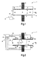
- Fig. 1 shows schematically the construction principle of a device 1 for generating a medium stream, wherein a diaphragm means 5 is arranged between two oppositely located chamber walls 2, 3, which, together with two lateral walls, not more specifically shown, that connect the chamber walls 2, 3 laterally (i.e. parallel to the plane of the drawing), define a cuboidal chamber formed by a channel 4 for the medium stream.
- This diaphragm means 5, hereinafter called diaphragm 5 for short is fixed with a rear end region 5.1 to the chamber wall 3 at the bottom according to the illustration in Fig.
- the diaphragm 5 is furthermore electrically isolated with respect to the chamber walls 2, 3, and generally electromechanical drive means 6 for energizing the diaphragm 5 are provided.
- conventional loudspeakers like for instance dynamic loudspeakers or electrostatic loudspeakers, in the case of the present device 1 the diaphragm 5 is not tensioned, despite the secured end regions 5.1 and 5.2, but in an inactive operating state of the device 1 is arranged loose or slack in the chamber formed by the channel 4.
- the drive means 6 comprise a control signal source 7, from which control signal source 7 in an active state of the device 1 an electrical control signal (or several control signals) corresponding to the particular sound to be generated is (are) applied to the diaphragm 5 and/or to electrodes formed by the chamber walls 2, 3.
- the diaphragm 5 comprises, for example, a thin metal foil, having a thickness in the micrometer range to nanometer range. A dielectric foil or a foil of doped silicon material or the like would also be possible.
- the opposite chamber walls 2, 3 are, as shown in Fig. 1 , specifically at different electrical potentials, which is indicated in Fig. 1 by the symbols "+" and a grounding symbol respectively, and the signal voltage is supplied to the diaphragm 5.
- the diaphragm 5 Depending on the voltage applied to the diaphragm 5, as supplied by the control signal source 7, the diaphragm 5 is drawn towards a chamber wall 2 or 3 and repelled from the respective other chamber wall 3 or 2, with the result that the diaphragm 5 is deformed in accordance with the natural laws of electrostatics.
- an air volume 8 With a deformation of the diaphragm 5 for instance as seen in Fig. 1 , namely from the position shown by solid lines into the position shown by broken lines, an air volume 8 is displaced and moved in the direction of the arrow 9.
- the direction of the displacement of the air volume in this embodiment of the device 1 is reversed again.
- Such a deformation of the diaphragm 5, and hence generation of a medium stream (gas volume) moved back and forth, is effected independently of the natural resonance of the diaphragm 5, but in accordance with the signal applied by the control signal source 7.
- That part of the diaphragm 5 that at any one time extends between the two oppositely located chamber walls 2, 3 can be called the transition portion 10, and this transition portion 10 is displaced corresponding to the imposed diaphragm deformation from the rear to the front in the direction of arrow 9 and then back in the opposite direction to the arrow, cf. also the intermediate position of the transition portion 10 in the illustration shown in Fig. 2 .
- the respective air volume on one side of the diaphragm 5 is expelled from the channel 4 (at one end thereof) by this displacement of the transition portion 10 of the diaphragm 5, but is sucked in on the other side.
- an air volume is displaced in the direction of the arrow 9 or in the opposite direction, and with correspondingly rapid displacement processes, with corresponding alternating electrical voltages issued from the control signal source 7 to the electrodes, corresponding sound waves are emitted.
- the maximum displaceable air volume is defined by the two extreme positions of the diaphragm 5 evident from Fig. 1 , that is, in particular between the two extreme positions of the transition portion 10.
- the maximum displaceable air volume, and hence the sound pressure of the generated sound wave per unit of area of the loudspeaker to depend only on the length d of the air channel, i.e. the channel 4, and not on the two other dimensions of the loudspeaker, i.e. the dimension in the direction transversely to the plane of the drawing in Fig. 1 and the distance between the two chamber walls 2, 3 respectively.
- the two other dimensions of the loudspeaker i.e. the dimension in the direction transversely to the plane of the drawing in Fig. 1 and the distance between the two chamber walls 2, 3 respectively.
- the mosaic-like area can comprise almost any geometrical areas, for example, circular, triangular, rectangular areas or irregular areas.
- the modules can additionally be arranged offset with respect to one another, whereby the resulting arrangement can be of layered construction. Such arrangements are advantageous when, in case of use as a loudspeaker in an appliance, only limited areas or volumes are available, such as, for example, in the case of mobile telephones or the like.
- the diaphragm 5 and/or the insulation 11 can have a rough or structured surface.
- mounting means 12 are indicated in Fig. 1 , which mounting means 12 carry the oppositely located chamber walls 2, 3 (as well as the lateral walls not shown), and are primarily intended to effect an acoustic separation of "front side” and “rear side” of the loudspeaker.
- Fig. 2 shows in a comparable schematic view a quite similar device 1 for generating sound by means of a slack diaphragm 5, the diaphragm 5 again being retained at the rear end of the lower chamber wall 3 and at the front end of the upper chamber wall 2 lying opposite the chamber wall 3, so that a transition portion 10 that moves in operation is formed between the two chamber walls 2, 3.
- this transition portion 10 of the diaphragm 5 is already located in an intermediate position compared with the two end positions apparent from Fig. 1 , and it is indicated in Fig. 2 by broken lines in a further intermediate position.
- the drive means 6 are realised by mounting electrodes 2.1, 2.2, 2.3 ... and 3.1, 3.2, 3.3 ... respectively (by way of non-limitative example only three electrodes are shown in each case) on the two chamber walls 2, 3, the two chamber walls 2, 3 moreover being in the form of insulators.
- the diaphragm 5 comprises, for example, again a thin conductive material, namely a thin metal foil. It should be mentioned that the diaphragm 5 can be formed from a thin doped silicon foil, optionally also from a thin dielectric material with an electrical charge applied thereto.
- Such a foil material with charge can be constructed, for example, from conventional polycarbonate foils per se, which are laid one on top of the other and are subjected to a drawing process. This produces a composite foil with cavities, and these cavities can be ionised by means of electron bombardment. The resulting electrical charge can be maintained at room temperature conditions for years.
- Such charged foils are already known per se and can also be used for the present purpose.
- the electrodes 2.1, 2.2, 2.3 ... and 3.1, 3.2, 3.3 ... respectively receive from a control signal source 7 via corresponding control lines 13 and 14 respectively a supply of signals, in order thus to draw the diaphragm 5 cyclically in portions towards the one chamber wall 2 and 3 respectively and to repel it from the other chamber wall 3 and 2 respectively.
- Fig. 2 illustrates, for example, the situation in which the diaphragm 5 (here having a negative potential) is drawn towards the first lower electrode 3.1 on the lower chamber wall 3.
- the further upper electrodes 2.2 and 2.3 are at this point in time still positively charged, so that the negative diaphragm 5 is attracted by them.
- the potential of the middle electrodes 2.2 (from + to -) and 3.2 (from - to +) respectively is then changed, so that the transition portion 10 moves further into the position shown by a broken line, in which the diaphragm 5 is then attracted in the middle region by the lower electrode 3.2.
- a similar control is effected in all other phases, so that upon corresponding control signals the diaphragm 5 is deformed cyclically in the described manner, with the transition portion 10 being displaced back and forth and hence with volumes of air being cyclically expelled and sucked in at each side of the device 1.
- the desired sound can be generated.
- the diaphragm 5 is constructed as a charged insulator (i.e. the diaphragm 5 has no potential connection)
- electrical repulsive forces can be exploited; in this case, the electrical signals applied from the signal source 7 can also have a relatively low voltage amplitude.
- the devices I described above with reference to Figures 1 and 2 can be assembled from just a few components, wherein all components can be manufactured from integrable solid-state elements.
- the construction can be modular, and the base element can be reduced in size virtually as desired.
- the individual modules are connected in parallel, the sound energy flux generated overall being proportional to the number of modules. Since, furthermore, the system is not operated at its natural frequency, the intrinsic properties of the sound source remain virtually influenced by the acoustic surroundings.
- the overall length d of the air channel (see Fig. 1 ) can be used for displacement of the air, and a substantially higher sound pressure can be generated.
- the ratio already mentioned above of useful volume (i.e. volume of the displaced air) to the total volume (overall volume) is greater by a factor of ten (10) than in the prior art.
- the sound energy flux generated is constant as a function of the frequency across the entire frequency range, and, furthermore, direct digital control signals are possible, as is apparent for example from the preceding explanation of the mode of operation of the device 1 according to Fig. 2 .
- An important advantage is the module principle, already mentioned several times, i.e. it is possible without power loss per unit of area to construct loudspeakers from individual modules.
- the linearity of the generated sound over the amplitude depends ultimately virtually only on the linearity of the flow rate as a function of the control signal; if desired, an electronic compensation can easily be provided here.
- the ends 15', 16' of the chambers of the device 1 shown in Fig. 1 or 2 are preferably open, i.e. they form openings for the displaced air or sucked-in air.
- Fig. 3 illustrates a device 1 for generating a medium stream that has been modified compared with Figs 1 and 2 , having a diaphragm 5 that is loose or slack in the inactive operating state of the device 1; in this case, in the active operating state of the device 1, a travelling wave is imposed on the diaphragm 5 by corresponding electrical excitation by means of drive means 6 still to be explained and only part of which is indicated.
- the device 1 according to Fig. 3 again contains a chamber having an upper chamber wall 2 and a lower chamber wall 3 lying opposite this upper chamber wall 2 (upper and lower again referring to the illustration in the drawing).
- the diaphragm 5 which in plan view is essentially rectangular, is arranged between these chamber walls 2, 3, the diaphragm 5 being fixed with its end regions 5.1 and 5.2 to a rear end wall 15 and a front end wall 16 respectively, in each case approximately in the geometrical middle between the two chamber walls 2, 3.
- the rear end region 5.1 of the diaphragm 5 is here equipped with a drive element 17, preferably in the form of a piezo element, via which drive element 17, similar to an excitation by a swinging rod, the diaphragm 5 is caused to oscillate starting from the rear end.
- This preferred excitation of oscillation at the end is combined with excitation of a travelling wave in the diaphragm 5 by alternating electrical potentials, which are applied to electrodes 2.1, 2.2, 2.3 ... and 3.1, 3.2, 3.3 ... respectively on the chambers walls 2, 3 - which incidentally again have an insulating function - from a signal source (rather like the illustration in Figs 2 to 7 ; this control has been omitted in Fig. 3 for the sake of simplicity).
- the diaphragm 5 itself again has, for example, a negative potential, which is likewise applied by a control line, for example, the control line 18 shown by a broken line in Fig. 2 .
- the diaphragm 5 can again be provided from the outset with a - negative - electrical charge, so that applying an electrical potential is unnecessary. It is likely, however, that the piezoelectric element drive element 17 according to Fig. 3 will have to be connected to a corresponding control output of the signal source 7 in order to effect excitation of oscillation with the desired frequency - matched to the frequency of the signals to the electrodes 2.1 to 3.3.
- the diaphragm 5 can comprise a thin metal foil in the micrometer or nanometer rang, and it has a constant thickness.
- the metal used for the diaphragm 5 can be, for example, as in the case of Figs 1 and 2 , aluminum.
- portions of the diaphragm are again, in a manner similar to that in the embodiment according to Fig. 2 , respectively attracted and repelled by electrodes, so that a waveform is generated; now, however, the activation is such that the wave-form deformation of the diaphragm 5 is a travelling wave or running wave, a different extreme position of the diaphragm 5 in Fig. 3 being represented by a broken line.
- the diaphragm 5 can also be manufactured with piezo element portions, as illustrated in Fig. 4 , i.e. the diaphragm 5 has a structured surface with piezoelectric layers separated from one another, cf. also Fig. 5 , which shows a portion of such a diaphragm 5 having "piezo elements" 20, 21, 22 and 23, 24, 25 respectively disposed on a plastics carrier film 5'.
- piezoelectric areas or piezo elements 20 to 25 are again connected by way of contacts and control lines, not more specifically shown, similar to the control lines 13 and 14 in Fig. 2 , to a signal source, similar to the signal source 7 in Fig. 2 , in order to excite a travelling wave in the diaphragm 5 by applying alternating potentials with suitable phase shift.
- This principle is indicated in Fig. 4 with polarity signs for the particular electrical bias voltages of the "piezo elements" (which are not more specifically shown); it should be added that the alternating potentials cause a positive and negative curvature respectively of the piezo layers, and hence a corresponding deformation of the diaphragm 5.
- the chamber itself with its chamber walls 2, 3, with the end walls 15, 16 and with the lateral walls, which are again present but not shown, can comprise an insulating material.
- retaining or mounting means 12 for the chamber of the device 1 in question are present. These retaining means 12 are again indicated only rather schematically in Figs 3 and 4 and moreover serve for an acoustic decoupling between front side and rear side.
- an even more intensive air displacement compared with that according to Figs 1 and 2 can be achieved, i.e. the ratio of useful volume (displaced air volume) to the volume of the component is even greater (for example 80% or 90% instead of 70%), compared with the embodiment according to Figs 1 and 2 .
- the ratio of useful volume (displaced air volume) to the volume of the component is even greater (for example 80% or 90% instead of 70%), compared with the embodiment according to Figs 1 and 2 .
- even more medium can be "pumped through" by means of the diaphragm 5 on which the travelling wave is imposed, wherein, for example, in the case of a sound generator, a travelling wave in the ultrasound range is generated, whereas a sound signal in the audible frequency range is defined by the varying overall air volume occurring on average.
- openings 27, 28 and 29, 30 respectively for the admission of medium and exit of medium respectively, in order thus to be able to draw in and expel medium (air) when the diaphragm 5 is deformed corresponding to the electromechanical excitation.
- the effect of these openings 27, 28 and 29, 30 respectively is that on the other side thereof, that is, between them and the respective adjacent end wall 15 and 16, cavities are left, which, as damping "cavities", effect a smoothing of the pulsating airflow generated on deformation of the diaphragm 5 in the manner of a travelling wave, so that outside the device 1 a virtually constant airflow for the short time units under consideration occurs.
- the amplitude of this airflow can be varied by the speed of the running wave, i.e. travelling wave, and thus by the frequency of the pulses in the case of pulsed excitation of the travelling wave, as is clear from Fig. 10 .
- the amplitudes of the airflow can consequently be varied in accordance with an emission of a sound wave.
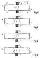
- a borderline case for a device 1 according to Fig. 3 or 4 is shown, namely, the case in which a single wave train is formed with the diaphragm 5.
- the diaphragm 5 is cyclically deformed, for example, starting from an approximately sinusoidal wave configuration, see Fig. 6 , wherein, as shown in Fig. 7 , in a first phase the rear portion, on the left in Fig.
- this mode of operation can be used to achieve a medium pump that can be adjusted and metered extraordinarily quickly and exactly, and is suitable especially for the transport of air or gas in general, but in principle also for the transport of liquid media.
- the piezoelectric diaphragm for instance according to Fig. 4 , can also be provided by producing a customary PZT material of a very small thickness (up to 1 ⁇ m), which is either applied to a carrier foil, or alternatively can be used directly as diaphragm, with individual portions of the diaphragm being insulated.
- Fig. 10 illustrates in a schematic diagram how a deformation and hence a travelling wave can be generated in a diaphragm, such as the diaphragm 5 according to Figures 1 to 9 , by means of comparatively short pulses 31 varying in pulse rate.
- the diaphragm is deformed with these pulses 31, so that, for example, an air volume is displaced alternately back and forth, so that a sound signal 32 having a lower frequency than the pulse rate is produced.
- the pulses 31 have an ultrasound frequency.
- a voltage-to-frequency converter 33 is used, to the input of which an electrical signal coming from an amplifier or similar useful signal circuit, not shown, is supplied, which reflects the desired sound signal (or optionally a control signal for metering medium volumes to be transported).
- an electrode control unit 35 Connected to the voltage-to-frequency converter 33 is an electrode control unit 35 with a pulse shaper and a shift register, which then activates or excites the diaphragm 5 or generally the device 1.
Description
- The invention relates to a device for generating a medium stream, which device comprises a chamber, the chamber comprising chamber walls lying opposite one another and at least one medium opening for the medium stream and being equipped with a diaphragm means, which diaphragm means is provided and constructed for generating the medium stream.
- Such a device in the form of a pump is known from the patent document
US 2002/0146333 A , which pump is provided for generating a pumped medium stream and with which pump a fluid medium is transported from one side of the chamber to the other side of the chamber by a diaphragm deformed analogous to a progressive wave or travelling wave. In the case of this known device, the slack, deformable diaphragm fixed at both ends has a defined thickness progression, and the fluid medium is transported from that end region of the chamber where the diaphragm is of relatively large thickness and is induced, for example, by means of e.g. a piezo element or a magnetic system, to oscillate in an undulating manner, to the opposite end of the chamber, where the thickness of the diaphragm is least. The wave induced in the diaphragm corresponds to a natural mode of the diaphragm, and is therefore not a forced oscillation having an adjustable running speed and an adjustable frequency. Such an excitation of the diaphragm is effected, as mentioned, at the admission end of the diaphragm, and, to generate the travelling wave, considerable damping as a consequence of the transported fluid is essential; the excitation frequency has to be kept low, for example in the range from 40 Hz to 80 Hz, in order to achieve an efficient transport of fluid. In the case of this known device, on the one hand, it is difficult to allow different flow rates across a relatively large variation range, and, on the other hand, it is also impossible to achieve miniaturisation. Furthermore, the known device is not suited to efficient transportation of gaseous media, since then the damping required for the natural resonance oscillation of the diaphragm is lacking. - Miniaturized conveying devices for gaseous media may in the future become increasingly important, however, especially when they allow an accurate metering or an exact setting and rapid change-over of the flow rates, as, for instance, in the case of an emission of odor substances. A need therefore exists here for the production of a device for generating a medium stream, especially in order to be able to transport and emit gaseous media in exactly metered quantities; this device shall moreover be capable of being realized in a miniaturized type of construction.
- On the other hand, it is known, for example, from the patent document
DE 4041 544 A , in an electrostatic loud speaker having a plurality of stationary electrodes to guide a diaphragm is a meandering manner back and forth around the plurality of stationary electrodes in order in this way to achieve a larger active surface and hence a larger oscillating area per unit of area of the loudspeaker. Individual diaphragm portions created by the meandering arrangement of the diaphragm are here tensioned as in conventional electrostatic loudspeakers and are located in chambers that are formed by respective opposite chamber walls and have a sound outlet opening. Despite the meandering arrangement of the diaphragm, the displaceable air volume compared with a single diaphragm of the same size is scarcely increased, so that the sound pressure also remains comparatively low. Above all, the ratio of displaceable air volume to overall product volume attains only relatively low values. - This known construction is moreover not capable of miniaturization, and an improvement of the ratio between the displaced air volume of the oscillating diaphragm and the overall volume would be necessary. Furthermore, a high offset voltage is needed, and without offset voltage it is not possible to operate the loudspeaker with the desired parameters.
- In the case of devices for generating a medium stream acting as loudspeakers, there is therefore a need for a model in which a high useful volume (i. e. a high volume of air moved by the diaphragm) in relation to the overall volume of the device required for the construction is achieved; additionally, a modular construction with no power loss is desirable, as well as a miniaturization of the device.
-
EP 0,322,899 discloses a pump comprising a piezo-electric vibrator mounted in a casing. The piezo-electric vibrator is coated with an elastic elastomer layer, and a peripheral part of the elastomer layer is secured to the casing within the casing. Suction and discharge of fluid is performed by means of a piezo-electric vibrator vibrated by applying alternative current voltages between electrodes of the piezo-electric vibrator. The vibration of the piezo-electric vibrator is performed smoothly to produce and high discharge volume and discharge pressure can be produced. - It is an object of the present invention to provide a device for generating a medium stream which is adapted for additional fields of application.
- This object may be achieved by a device according to the independent claim.
- In such a device, a medium stream can be generated with accurately definable and quickly adjustable metering, wherein any desired frequencies for the deformation of the diaphragm shall be possible; it shall also be possible to construct the device with few components and the device shall be capable of being used in a miniaturized construction, e. g. as a loudspeaker for mobile telephone hand-held devices.
- The invention therefore provides, in accordance with a main aspect, a device for generating a medium stream that can be characterized in the manner specified hereinafter, namely:
- A device for generating a medium stream, which device comprises a chamber, which chamber comprises chamber walls lying opposite one another and at least one medium opening for the medium stream and is equipped with a diaphragm means, which diaphragm means is provided and constructed for generating the medium stream and which diaphragm means, in an inactive operating state of the device, is arranged untensioned in the chamber between the chamber walls and which diaphragm means has associated with it drive means, responsive to electrical drive signals, for driving the diaphragm means with the diaphragm means undergoing deformation, the drive means being arranged to impose a deformation on the diaphragm means in an active operating state of the device, during which deformation the diaphragm means have an inner mechanical tension.
- The great advantage of the device according to the invention is that the drive means for driving the diaphragm means are preferably provided or are effective over substantially the entire (effective) length of the diaphragm means and/or of the chamber.
- In an active operating state of the device according to the invention, the diaphragm means or the diaphragm is therefore not (or not necessarily) operated in a natural mode, and an excitation or the driving of the diaphragm can be effected over the entire diaphragm area, in which case a comparatively uniform behaviour is achievable. Driving of the diaphragm means is effected in such a way that a deformation of the diaphragm means is caused, the diaphragm means then having or developing an inner mechanical tension and a mechanical strength being consequently given to the diaphragm means, thus enabling the medium stream to be generated.
- The device is capable of being easily integrated, i.e. is capable of miniaturization, without having to accept power losses. When constructed as a loud speaker, it is accordingly possible to realise loudspeakers from individual small modules without power loss in relation to the area; on the other hand, in the case of miniaturized loudspeakers, it is possible to achieve sound pressures such as those possible in the art only for larger loudspeakers.
- When the device according to the present invention is used to realise a loudspeaker, then the loose or "slack" diaphragm provided in an inactive operating state of the device represents a complete departure from all previous loudspeaker systems, in which the diaphragm, even if it was optionally guided back and forth, was tensioned mechanically, both in an active and in an inactive operating state of the loud speaker system. The device according to the invention with the diaphragm means or the diaphragm and its high degree of deformation is able, however, to move a large air volume compared with the conventional loudspeakers, so that an extremely high useful volume, in relation to the overall volume of the loudspeaker, can be achieved. In the case of conventional electrodynamic or electrostatic loudspeaker systems, which without exception are based on resonance, the ratio of useful volume to overall volume is regularly below 10% - especially around 7%. With the device according to the invention, however, a useful volume (in relation to the overall volume) of 70%, 80% or even 90% (i.e. higher by a factor of 10) can be achieved. The diaphragm means can in this case position itself against the chamber walls, in which case, depending on construction, a thin insulating layer will then be provided on the chamber walls, the walls, at least in sections, being able to function as electrodes, or the insulating layer will be provided on the diaphragm means itself. In order to realise the drive system, it is also conceivable to provide a diaphragm means provided with an electrical charge, in which case the electrical charge of the diaphragm means is maintained over a period of years with no substantial losses (such foils provided with an electrical charge are per se already state of the art). Another possibility for the construction of the diaphragm means consists in providing on the diaphragm means, in sections, piezoelectric sections or coatings which are isolated from one another electrically and, when corresponding electrical voltages are applied, exert mechanical forces for the purpose of deforming the diaphragm means. A metal foil can be used for the diaphragm means, to which an electrical voltage is applied relative to electrodes provide in the region of the chamber walls, so that the diaphragm means deforms in the alternating field between the electrodes and is consequently imparted the inner mechanical tension. A foil of a dielectric material is also conceivable for realization of the diaphragm means.
- The diaphragm means can be fixed in the chamber with two spaced apart end regions, wherein between these end regions the diaphragm means has a loose or slack configuration, as mentioned above, and then, in the active operating state, is deformable for the purpose of displacing a large volume of medium and develops an inner mechanical tension.
- In order to assist the drive, i.e. the electromechanical drive means or excitation means, for the diaphragm means for desired deformation of the diaphragm means, an electromechanical drive element, such as especially a piezomechanical element, can act additionally on the diaphragm means at the end thereof, this drive element assisting the generation of a travelling wave of the diaphragm means by means of electrodes mounted on the diaphragm means and/or on the chamber walls.
- The chamber can be in the form of a channel, that is, substantially cuboidal, openings for the displaced medium, especially gaseous medium, being provided in the region of the opposite end walls. The diaphragm means has furthermore, as is especially preferred, a substantially constant thickness over its length, by which inter alia the advantage of a comparatively simple manufacture is achieved.
- As already mentioned, in the device according to the invention provision is advantageously made for the diaphragm means, by suitable control of the drive means, to undergo in operation a deformation corresponding to a progressive wave or travelling wave; it is conceivable, however, for the diaphragm means to be fixed with its end regions to the chamber walls lying opposite one another and to be arranged therebetween in such a way that, in operation or in the active operating state, a travelling transition portion extends substantially between the chamber walls lying opposite one another, more or less at right angles or slightly obliquely with respect to the chamber walls. This transition portion extending from the one chamber wall to the other is displaced continuously back and forth between the two ends and the at least one medium opening of the chamber respectively by means of the correspondingly designed drive means. The chamber forms also in this case preferably an on the whole cuboidal channel of rectangular cross-section. Because of the displacement back and forth of volumes, this construction is not, however, suitable as a pump, but is very suitable as a sound generator (loudspeaker), wherein a comparatively large volume of air is displaced back and forth. Since the sound pressure is approximately proportional to the displaced volume of air, a substantially smaller loudspeaker with no power loss can be assembled, in particular from individual small modules. It must be remembered here that in the case of current miniaturized loudspeakers, in which only very small air volumes can be displaced, a minimum sound level is produced, so that these small loudspeakers are used only at or in the ear. By way of comparison, in the case of the device according to the present invention, as mentioned,
air volumes 10 times as large are displaced, i.e. the ratio of displaced air volume to overall volume of the component is substantially increased, so that applications of comparably small loudspeakers away from the ear are possible and, at predetermined sound levels, substantially smaller overall sizes. - A somewhat better ratio of displaced air volume to overall volume can be achieved in the case of the above-described travelling wave construction option, in which the diaphragm means, as mentioned, is deformed analogous to a travelling wave - the frequency of which can lie in the ultrasound range. With this travelling wave diaphragm, at least one full wave train of the displaced diaphragm means is provided; preferably, however, the diaphragm means can be deformed by a longer wave train, for instance corresponding to 1½ or 2 wavelengths. Here too, the diaphragm means can be caused by different drive sources to execute undulatory displacements of pre-determinable frequency, the displacements of the diaphragm means producing a travelling wave. The travelling wave of the diaphragm means generates an air stream varying in time in one direction, similar to a "air pump", wherein optionally a smoothing can be incorporated; the intensity or amplitude of the air stream can be varied by the speed of the travelling wave, that is, by the frequency of the pulses where the travelling wave is induced by pulses. In the borderline case with a single wave train, one cannot, strictly speaking, talk of a travelling wave any more, the deformation of the diaphragm means is reduced substantially to an oscillation with a high proportion of a second harmonic and a fixed phase relation to one another.
- These and other aspects of the invention are apparent from and will be elucidated, by way of non-limitative example, with reference to the embodiments described hereinafter.
- In the drawings:
-
Fig. 1 shows schematically a longitudinal section through a device for generating a medium stream in the form of a loudspeaker, two end positions of the diaphragm means relative to two chamber walls lying opposite one another being illustrated. -
Fig. 2 shows in a comparable longitudinal section a similar loudspeaker device, but with drive means that have been modified with respect toFig. 1 , an intermediate position of the diaphragm means in operation additionally being shown. -
Fig. 3 shows another embodiment of the present invention for generating a medium stream, which is based on the principle of a forced travelling wave and can be used both as a loudspeaker and as a pump. -
Fig. 4 shows in a comparable schematic longitudinal sectional view a similar device with travelling wave diaphragm means, but with modified drive means. -
Fig. 5 shows in a schematic and fragmentary view a diaphragm means with piezo material layers. -
Figures 6 to 9 show a further device of the kind shown inFigs 3 and 4 , but with a diaphragm means in which only a single wave train is formed, the diaphragm means being shown at different points in time, i.e. in different states of deformation. -
Fig. 10 shows a diagram of the signal pulses to be applied to the diaphragm drive means and the resulting sound signal when the device according toFig. 3 or 4 is constructed for instance as a loudspeaker. -
Fig. 11 shows a block diagram for the control of such a device (according toFig. 10 ). -
Fig. 1 shows schematically the construction principle of adevice 1 for generating a medium stream, wherein a diaphragm means 5 is arranged between two oppositely locatedchamber walls chamber walls channel 4 for the medium stream. This diaphragm means 5, hereinafter calleddiaphragm 5 for short, is fixed with a rear end region 5.1 to thechamber wall 3 at the bottom according to the illustration inFig. 1 , and with the opposite other front end region 5.2 is fixed to the other,upper chamber wall 2, so that in relation to thecuboidal channel 4 the two fixing regions lie diametrically opposite one another. Thediaphragm 5 is furthermore electrically isolated with respect to thechamber walls diaphragm 5 are provided. Unlike conventional loudspeakers, like for instance dynamic loudspeakers or electrostatic loudspeakers, in the case of thepresent device 1 thediaphragm 5 is not tensioned, despite the secured end regions 5.1 and 5.2, but in an inactive operating state of thedevice 1 is arranged loose or slack in the chamber formed by thechannel 4. - According to
Fig. 1 , the drive means 6 comprise a control signal source 7, from which control signal source 7 in an active state of thedevice 1 an electrical control signal (or several control signals) corresponding to the particular sound to be generated is (are) applied to thediaphragm 5 and/or to electrodes formed by thechamber walls diaphragm 5 comprises, for example, a thin metal foil, having a thickness in the micrometer range to nanometer range. A dielectric foil or a foil of doped silicon material or the like would also be possible. Theopposite chamber walls Fig. 1 , specifically at different electrical potentials, which is indicated inFig. 1 by the symbols "+" and a grounding symbol respectively, and the signal voltage is supplied to thediaphragm 5. Depending on the voltage applied to thediaphragm 5, as supplied by the control signal source 7, thediaphragm 5 is drawn towards achamber wall other chamber wall diaphragm 5 is deformed in accordance with the natural laws of electrostatics. With a deformation of thediaphragm 5 for instance as seen inFig. 1 , namely from the position shown by solid lines into the position shown by broken lines, anair volume 8 is displaced and moved in the direction of thearrow 9. Upon a deformation subsequent thereto back into the position shown by solid lines, the direction of the displacement of the air volume in this embodiment of thedevice 1 is reversed again. Such a deformation of thediaphragm 5, and hence generation of a medium stream (gas volume) moved back and forth, is effected independently of the natural resonance of thediaphragm 5, but in accordance with the signal applied by the control signal source 7. That part of thediaphragm 5 that at any one time extends between the two oppositely locatedchamber walls transition portion 10, and thistransition portion 10 is displaced corresponding to the imposed diaphragm deformation from the rear to the front in the direction ofarrow 9 and then back in the opposite direction to the arrow, cf. also the intermediate position of thetransition portion 10 in the illustration shown inFig. 2 . The respective air volume on one side of thediaphragm 5 is expelled from the channel 4 (at one end thereof) by this displacement of thetransition portion 10 of thediaphragm 5, but is sucked in on the other side. In this way, as mentioned above, an air volume is displaced in the direction of thearrow 9 or in the opposite direction, and with correspondingly rapid displacement processes, with corresponding alternating electrical voltages issued from the control signal source 7 to the electrodes, corresponding sound waves are emitted. The maximum displaceable air volume is defined by the two extreme positions of thediaphragm 5 evident fromFig. 1 , that is, in particular between the two extreme positions of thetransition portion 10. Unlike the case of a dynamic loudspeaker, however, in the case of thedevice 1 shown it is possible for the maximum displaceable air volume, and hence the sound pressure of the generated sound wave per unit of area of the loudspeaker, to depend only on the length d of the air channel, i.e. thechannel 4, and not on the two other dimensions of the loudspeaker, i.e. the dimension in the direction transversely to the plane of the drawing inFig. 1 and the distance between the twochamber walls Fig. 1 can be arranged side by side, that is, parallel to the plane of the drawing, and above one another and below one another respectively, and be controlled in parallel. Such an arrangement of several modules then produces a mosaic-like area in relation to the sound outlet openings, in which case the mosaic-like area can comprise almost any geometrical areas, for example, circular, triangular, rectangular areas or irregular areas. The modules can additionally be arranged offset with respect to one another, whereby the resulting arrangement can be of layered construction. Such arrangements are advantageous when, in case of use as a loudspeaker in an appliance, only limited areas or volumes are available, such as, for example, in the case of mobile telephones or the like. - Since the
diaphragm 5 positions itself against thechamber walls chamber walls Fig. 1 for the sake of simplicity this is shown only schematically at theupper chamber wall 2 with aninsulation 11. A corresponding insulation can alternatively, however, be provided on thediaphragm 5 itself. - In order to counteract any physical forces (for example, van de Waals forces) occurring between the
diaphragm 5 and theinsulation 11, thediaphragm 5 and/or theinsulation 11 can have a rough or structured surface. - Furthermore, mounting means 12 are indicated in
Fig. 1 , which mounting means 12 carry the oppositely locatedchamber walls 2, 3 (as well as the lateral walls not shown), and are primarily intended to effect an acoustic separation of "front side" and "rear side" of the loudspeaker. -
Fig. 2 shows in a comparable schematic view a quitesimilar device 1 for generating sound by means of aslack diaphragm 5, thediaphragm 5 again being retained at the rear end of thelower chamber wall 3 and at the front end of theupper chamber wall 2 lying opposite thechamber wall 3, so that atransition portion 10 that moves in operation is formed between the twochamber walls Fig. 2 , thistransition portion 10 of thediaphragm 5 is already located in an intermediate position compared with the two end positions apparent fromFig. 1 , and it is indicated inFig. 2 by broken lines in a further intermediate position. - Unlike the case in
Fig. 1 , in this case the drive means 6 are realised by mounting electrodes 2.1, 2.2, 2.3 ... and 3.1, 3.2, 3.3 ... respectively (by way of non-limitative example only three electrodes are shown in each case) on the twochamber walls chamber walls diaphragm 5 comprises, for example, again a thin conductive material, namely a thin metal foil. It should be mentioned that thediaphragm 5 can be formed from a thin doped silicon foil, optionally also from a thin dielectric material with an electrical charge applied thereto. Such a foil material with charge can be constructed, for example, from conventional polycarbonate foils per se, which are laid one on top of the other and are subjected to a drawing process. This produces a composite foil with cavities, and these cavities can be ionised by means of electron bombardment. The resulting electrical charge can be maintained at room temperature conditions for years. Such charged foils are already known per se and can also be used for the present purpose. - The electrodes 2.1, 2.2, 2.3 ... and 3.1, 3.2, 3.3 ... respectively (more than the three electrodes shown in each case can also of course be mounted on the
chamber walls 2, 3) receive from a control signal source 7 via correspondingcontrol lines diaphragm 5 cyclically in portions towards the onechamber wall other chamber wall Fig. 2 illustrates, for example, the situation in which the diaphragm 5 (here having a negative potential) is drawn towards the first lower electrode 3.1 on thelower chamber wall 3. The further upper electrodes 2.2 and 2.3 are at this point in time still positively charged, so that thenegative diaphragm 5 is attracted by them. In the next phase, the potential of the middle electrodes 2.2 (from + to -) and 3.2 (from - to +) respectively is then changed, so that thetransition portion 10 moves further into the position shown by a broken line, in which thediaphragm 5 is then attracted in the middle region by the lower electrode 3.2. A similar control is effected in all other phases, so that upon corresponding control signals thediaphragm 5 is deformed cyclically in the described manner, with thetransition portion 10 being displaced back and forth and hence with volumes of air being cyclically expelled and sucked in at each side of thedevice 1. In this way, with corresponding frequencies of the deformation of thediaphragm 5, in turn the desired sound can be generated. If thediaphragm 5 is constructed as a charged insulator (i.e. thediaphragm 5 has no potential connection), electrical repulsive forces can be exploited; in this case, the electrical signals applied from the signal source 7 can also have a relatively low voltage amplitude. - The devices I described above with reference to
Figures 1 and 2 can be assembled from just a few components, wherein all components can be manufactured from integrable solid-state elements. The construction can be modular, and the base element can be reduced in size virtually as desired. Depending on the power requirement, the individual modules are connected in parallel, the sound energy flux generated overall being proportional to the number of modules. Since, furthermore, the system is not operated at its natural frequency, the intrinsic properties of the sound source remain virtually influenced by the acoustic surroundings. Compared with conventional loudspeaker systems, especially dynamic loudspeakers, the overall length d of the air channel (seeFig. 1 ) can be used for displacement of the air, and a substantially higher sound pressure can be generated. In particular, the ratio already mentioned above of useful volume (i.e. volume of the displaced air) to the total volume (overall volume) is greater by a factor of ten (10) than in the prior art. The sound energy flux generated is constant as a function of the frequency across the entire frequency range, and, furthermore, direct digital control signals are possible, as is apparent for example from the preceding explanation of the mode of operation of thedevice 1 according toFig. 2 . An important advantage is the module principle, already mentioned several times, i.e. it is possible without power loss per unit of area to construct loudspeakers from individual modules. The linearity of the generated sound over the amplitude depends ultimately virtually only on the linearity of the flow rate as a function of the control signal; if desired, an electronic compensation can easily be provided here. - The ends 15', 16' of the chambers of the
device 1 shown inFig. 1 or 2 are preferably open, i.e. they form openings for the displaced air or sucked-in air. -
Fig. 3 illustrates adevice 1 for generating a medium stream that has been modified compared withFigs 1 and 2 , having adiaphragm 5 that is loose or slack in the inactive operating state of thedevice 1; in this case, in the active operating state of thedevice 1, a travelling wave is imposed on thediaphragm 5 by corresponding electrical excitation by means of drive means 6 still to be explained and only part of which is indicated. Thedevice 1 according toFig. 3 again contains a chamber having anupper chamber wall 2 and alower chamber wall 3 lying opposite this upper chamber wall 2 (upper and lower again referring to the illustration in the drawing). - The
diaphragm 5, which in plan view is essentially rectangular, is arranged between thesechamber walls diaphragm 5 being fixed with its end regions 5.1 and 5.2 to arear end wall 15 and afront end wall 16 respectively, in each case approximately in the geometrical middle between the twochamber walls diaphragm 5 is here equipped with adrive element 17, preferably in the form of a piezo element, via which driveelement 17, similar to an excitation by a swinging rod, thediaphragm 5 is caused to oscillate starting from the rear end. This preferred excitation of oscillation at the end is combined with excitation of a travelling wave in thediaphragm 5 by alternating electrical potentials, which are applied to electrodes 2.1, 2.2, 2.3 ... and 3.1, 3.2, 3.3 ... respectively on thechambers walls 2, 3 - which incidentally again have an insulating function - from a signal source (rather like the illustration inFigs 2 to 7 ; this control has been omitted inFig. 3 for the sake of simplicity). Thediaphragm 5 itself again has, for example, a negative potential, which is likewise applied by a control line, for example, thecontrol line 18 shown by a broken line inFig. 2 . As an alternative to this, thediaphragm 5 can again be provided from the outset with a - negative - electrical charge, so that applying an electrical potential is unnecessary. It is likely, however, that the piezoelectricelement drive element 17 according toFig. 3 will have to be connected to a corresponding control output of the signal source 7 in order to effect excitation of oscillation with the desired frequency - matched to the frequency of the signals to the electrodes 2.1 to 3.3. - Also in the embodiment according to
Fig. 3 , thediaphragm 5 can comprise a thin metal foil in the micrometer or nanometer rang, and it has a constant thickness. The metal used for thediaphragm 5 can be, for example, as in the case ofFigs 1 and 2 , aluminum. - By the controlled, pulse-form application of the alternating electrical potentials to the electrodes 2.1 etc., portions of the diaphragm are again, in a manner similar to that in the embodiment according to
Fig. 2 , respectively attracted and repelled by electrodes, so that a waveform is generated; now, however, the activation is such that the wave-form deformation of thediaphragm 5 is a travelling wave or running wave, a different extreme position of thediaphragm 5 inFig. 3 being represented by a broken line. - In the embodiment according to
Fig. 3 , comparatively high electrical fields are necessary in order to generate the travelling wave at thediaphragm 5. In order to satisfy requirements with lower electrical voltages, thediaphragm 5 can also be manufactured with piezo element portions, as illustrated inFig. 4 , i.e. thediaphragm 5 has a structured surface with piezoelectric layers separated from one another, cf. alsoFig. 5 , which shows a portion of such adiaphragm 5 having "piezo elements" 20, 21, 22 and 23, 24, 25 respectively disposed on a plastics carrier film 5'. These piezoelectric areas orpiezo elements 20 to 25 are again connected by way of contacts and control lines, not more specifically shown, similar to thecontrol lines Fig. 2 , to a signal source, similar to the signal source 7 inFig. 2 , in order to excite a travelling wave in thediaphragm 5 by applying alternating potentials with suitable phase shift. This principle is indicated inFig. 4 with polarity signs for the particular electrical bias voltages of the "piezo elements" (which are not more specifically shown); it should be added that the alternating potentials cause a positive and negative curvature respectively of the piezo layers, and hence a corresponding deformation of thediaphragm 5. In this case of the embodiment according toFig. 4 , the chamber itself with itschamber walls end walls - It should be mentioned that in the case of the embodiments according to
Figs 3 and 4 , retaining or mounting means 12 for the chamber of thedevice 1 in question are present. These retaining means 12 are again indicated only rather schematically inFigs 3 and 4 and moreover serve for an acoustic decoupling between front side and rear side. - In addition, the running direction of the travelling wave in the
diaphragm 5 is indicated inFigures 3 and 4 witharrows 26 and 26' respectively. - With a device such as that shown in
Fig. 3 or 4 , an even more intensive air displacement compared with that according toFigs 1 and 2 can be achieved, i.e. the ratio of useful volume (displaced air volume) to the volume of the component is even greater (for example 80% or 90% instead of 70%), compared with the embodiment according toFigs 1 and 2 . In other words, with a device according toFig. 3 or 4 even more medium can be "pumped through" by means of thediaphragm 5 on which the travelling wave is imposed, wherein, for example, in the case of a sound generator, a travelling wave in the ultrasound range is generated, whereas a sound signal in the audible frequency range is defined by the varying overall air volume occurring on average. - From
Figures 3 and 4 it is furthermore apparent that in theopposite chamber walls end walls openings diaphragm 5 is deformed corresponding to the electromechanical excitation. The effect of theseopenings adjacent end wall diaphragm 5 in the manner of a travelling wave, so that outside the device 1 a virtually constant airflow for the short time units under consideration occurs. The amplitude of this airflow can be varied by the speed of the running wave, i.e. travelling wave, and thus by the frequency of the pulses in the case of pulsed excitation of the travelling wave, as is clear fromFig. 10 . At high excitation frequencies or with rapidly travelling waves, the amplitudes of the airflow can consequently be varied in accordance with an emission of a sound wave. Depending on the nature of the excitation of thediaphragm 5, it is possible for the travelling wave to be excited alternately in the one and in the other direction, with the result that a mode of operation similar to that ofFigs 1 and 2 is achieved; with this mode of operation, a constant portion of the flow of air is advantageously avoided, so that only a varying amplitude portion of the flow of air is provided for the sound generation. - In
Fig. 6 and in the associatedFigures 7, 8 and 9 , in which different operational phases are shown, a borderline case for adevice 1 according toFig. 3 or 4 is shown, namely, the case in which a single wave train is formed with thediaphragm 5. In that case, by the applied alternating potentials (either at electrodes as shown inFig. 3 or at "piezo elements" on thediaphragm 5 itself, as illustrated inFig. 4 ) thediaphragm 5 is cyclically deformed, for example, starting from an approximately sinusoidal wave configuration, seeFig. 6 , wherein, as shown inFig. 7 , in a first phase the rear portion, on the left inFig. 7 , of thediaphragm 5 is drawn downwards, whilst the middle portion of thediaphragm 5 is drawn upwards; following that, the front portion, on the right in the drawing, of thediaphragm 5, is drawn upwards, seeFig. 8 , so that a position of thediaphragm 5 opposite in phase compared withFig. 6 is obtained. Subsequently the left or rather rear portion of thediaphragm 5 is again drawn upwards, whereas the middle portion is drawn downwards, cf.Fig. 9 , this configuration of thewave 5 according toFig. 9 being opposite in phase to that according toFig. 7 . Next, the state shown inFig. 6 is reached again. This movement of thediaphragm 5 is thus reduced compared with a longer wave train, for instance according toFig. 3 or 4 , essentially to an oscillation with a high proportion of a second harmonic with a fixed phase relation. - With the devices according to
Figs 3 to 9 , likewise only a small number of components is necessary, and it is likewise of advantage that here too all components can be manufactured from integrable solid-state elements. Miniaturisation more or less as desired is likewise possible, likewise a modular construction, the sound flux being as a whole proportional to the number of the individual modules. - Furthermore, where a medium stream is generated always in one direction, for instance from left to right, in accordance with the
arrows 26 and 26' respectively inFigs 3 and 4 , it is possible to achieve a uniform flow, so that in the case of a loudspeaker the lower limiting frequency is 0 Hz. On the other hand, this mode of operation can be used to achieve a medium pump that can be adjusted and metered extraordinarily quickly and exactly, and is suitable especially for the transport of air or gas in general, but in principle also for the transport of liquid media. Here too, digital activation signals are again possible, and the linearity over the amplitude (few harmonic waves) depends virtually only on the linearity of the flow rate as a function of the control signal, wherein optionally, if desired, an electronic compensation can be provided. As far as the principle goes, the generated sound flux of the sound source as a function of the frequency is likewise constant over the entire frequency range, and it is possible to construct a loudspeaker from individual modules without power loss per unit of area. - The piezoelectric diaphragm, for instance according to
Fig. 4 , can also be provided by producing a customary PZT material of a very small thickness (up to 1 µm), which is either applied to a carrier foil, or alternatively can be used directly as diaphragm, with individual portions of the diaphragm being insulated. -
Fig. 10 illustrates in a schematic diagram how a deformation and hence a travelling wave can be generated in a diaphragm, such as thediaphragm 5 according toFigures 1 to 9 , by means of comparativelyshort pulses 31 varying in pulse rate. The diaphragm is deformed with thesepulses 31, so that, for example, an air volume is displaced alternately back and forth, so that asound signal 32 having a lower frequency than the pulse rate is produced. Compared to thissound signal 32 in the audible frequency range, thepulses 31 have an ultrasound frequency. - In order to generate
such pulses 31, or rather in general a control signal, according toFig. 11 a voltage-to-frequency converter 33 is used, to the input of which an electrical signal coming from an amplifier or similar useful signal circuit, not shown, is supplied, which reflects the desired sound signal (or optionally a control signal for metering medium volumes to be transported). Connected to the voltage-to-frequency converter 33 is anelectrode control unit 35 with a pulse shaper and a shift register, which then activates or excites thediaphragm 5 or generally thedevice 1. - It should be mentioned that as far as the deformations of the
diaphragm 5, especially the curvatures thereof, are concerned, the illustrations in the drawings are only schematic and somewhat exaggerated; in practice, thediaphragms 5 will experience smaller curvatures and deflections, i.e. the ratio of height to length will be smaller.
Claims (22)
- A device (1) for generating a medium stream, which device (1) comprises a chamber (4), which chamber (4) comprises chamber walls (2, 3) lying opposite one another and at least one medium opening (15', 16', 27, 28, 29, 30) for the medium stream (8) and is equipped with a diaphragm means (5), which diaphragm means (5) is provided and constructed for generating the medium stream (8) and which diaphragm means (5), in an inactive operating state of the device (1), is arranged untensioned in the chamber (4) between the chamber walls (2, 3) and associated with which diaphragm means (5) are drive means (6), responsive to electrical drive signals, for driving the diaphragm means (5) to deform the same, the drive means (6) being arranged to impose a deformation on the diaphragm means (5) in an active operating state of the device (1), during which deformation the diaphragm means (5) have an inner mechanical tension, wherein the device (1) is provided for the generation of sound by means of the medium stream generated.
- A device (1) as claimed in claim 1, wherein the drive means (6) comprise electrodes (2.1, 2.2 ... 3.3) arranged on the chamber walls (2, 3) lying opposite one another.
- A device (1) as claimed in claim 2, wherein the diaphragm means (5) comprises a metal foil.
- A device (1) as claimed in claim 2, wherein the diaphragm means (5) comprises a foil made of a dielectric material.
- A device (1) as claimed in claim 1, wherein the diaphragm means (5) consists at least partly of piezoelectric material.
- A device (1) as claimed in claim 5, wherein the diaphragm means (5) comprises an electrode.
- A device (1) as claimed in claim 1, wherein the diaphragm means (5) comprises two end regions (5.1, 5.2) provided a distance apart from one another, which end regions (5.1, 5.2) are fixed in the chamber (4).
- A device (1) as claimed in claim 1, wherein the drive means (6) contain an electromechanical drive element (17), and the diaphragm means (5) has an end portion (5.1) that is connected to the electromechanical drive element (17).
- A device (1) as claimed in claim 1, wherein the chamber (4) is of substantially cuboidal construction and comprises two end walls (15, 16) lying opposite one another.
- A device (1) as claimed in claim 1, wherein the chamber (4) comprises at least two medium openings (27, 28, 29, 30) provided spaced apart from one another.
- A device (1) as claimed in claim 1, wherein the diaphragm means (5) has an at least substantially constant thickness.
- A device (1) as claimed in claim 9, wherein the diaphragm means (5) is fixed with two opposing end regions (5.1., 5.2) to the end walls (15, 16) of the essentially cuboidal chamber (4).
- A device (1) as claimed in claim 1, wherein the drive means (6) are designed to impose a deformation having at least a pre-determinable frequency.
- A device (1) as claimed in claim 12, wherein the drive means (6) are designed to impose a cyclic deformation in the form of a traveling wave on the diaphragm means (5).
- A device (1) as claimed in claim 9, wherein the diaphragm means (5) is fixed with one end region (5.1) close to one end of the cuboidal chamber (4) to the one chamber wall (3) of the mutually opposed chamber walls (2, 3) and with an opposite end region (5.2) close to the opposite end of the chamber (4) to the other chamber wall (2) of the mutually opposed chamber walls (2, 3).
- A device (1) as claimed in claim 15, wherein the diaphragm means (5) comprises a transition portion (10) extending in operation substantially at right angles to the chamber walls (2, 3) lying opposite one another.
- A device (1) as claimed in claim 15, wherein medium openings (15', 16') are provided at both ends of the chamber (4).
- A device (1) as claimed in claim 1, in which device (1) the medium stream (8) is a stream of a gaseous medium.
- A device (1) as claimed in claim 1, which is provided as pump device for the medium stream.
- A device (1) as claimed in any one of the preceding claims, wherein a number of chambers (4) are provided in the device (1), which chambers (4) are arranged in one unit.
- A device (1) as claimed in claim 1, wherein the diaphragm means (5) and/or the chamber walls (2, 3) have an insulating layer (11).
- A device (1) as claimed in claim 2, wherein the diaphragm means (5) and/or the chamber walls (2, 3) have a structured surface.
Priority Applications (2)
| Application Number | Priority Date | Filing Date | Title |
|---|---|---|---|
| EP04737203A EP1644639B1 (en) | 2003-06-30 | 2004-06-28 | Device for generating sound by means of a medium stream generated |
| US10/562,873 US7889877B2 (en) | 2003-06-30 | 2004-06-28 | Device for generating a medium stream |
Applications Claiming Priority (3)
| Application Number | Priority Date | Filing Date | Title |
|---|---|---|---|
| EP03101954 | 2003-06-30 | ||
| EP04737203A EP1644639B1 (en) | 2003-06-30 | 2004-06-28 | Device for generating sound by means of a medium stream generated |
| PCT/IB2004/051029 WO2005001287A1 (en) | 2003-06-30 | 2004-06-28 | Device for generating a medium stream |
Publications (2)
| Publication Number | Publication Date |
|---|---|
| EP1644639A1 EP1644639A1 (en) | 2006-04-12 |
| EP1644639B1 true EP1644639B1 (en) | 2009-02-11 |
Family
ID=36046493
Family Applications (1)
| Application Number | Title | Priority Date | Filing Date |
|---|---|---|---|
| EP04737203A Not-in-force EP1644639B1 (en) | 2003-06-30 | 2004-06-28 | Device for generating sound by means of a medium stream generated |
Country Status (2)
| Country | Link |
|---|---|
| US (1) | US7889877B2 (en) |
| EP (1) | EP1644639B1 (en) |
Cited By (7)
| Publication number | Priority date | Publication date | Assignee | Title |
|---|---|---|---|---|
| US9968720B2 (en) | 2016-04-11 | 2018-05-15 | CorWave SA | Implantable pump system having an undulating membrane |
| US10166319B2 (en) | 2016-04-11 | 2019-01-01 | CorWave SA | Implantable pump system having a coaxial ventricular cannula |
| US10188779B1 (en) | 2017-11-29 | 2019-01-29 | CorWave SA | Implantable pump system having an undulating membrane with improved hydraulic performance |
| US10799625B2 (en) | 2019-03-15 | 2020-10-13 | CorWave SA | Systems and methods for controlling an implantable blood pump |
| US10933181B2 (en) | 2017-03-31 | 2021-03-02 | CorWave SA | Implantable pump system having a rectangular membrane |
| US11191946B2 (en) | 2020-03-06 | 2021-12-07 | CorWave SA | Implantable blood pumps comprising a linear bearing |
| US11512689B2 (en) | 2017-11-10 | 2022-11-29 | CorWave SA | Undulating-membrane fluid circulator |
Families Citing this family (14)
| Publication number | Priority date | Publication date | Assignee | Title |
|---|---|---|---|---|
| JP2010051430A (en) * | 2008-08-27 | 2010-03-11 | Seiko Epson Corp | Pulse generating mechanism, connection flow channel tube, fluid ejection apparatus |
| US8879775B2 (en) | 2010-02-17 | 2014-11-04 | Viking At, Llc | Smart material actuator capable of operating in three dimensions |
| WO2012079012A2 (en) | 2010-12-09 | 2012-06-14 | Viking At, Llc | Multiple arm smart material actuator with second stage |
| GB201202346D0 (en) * | 2012-02-10 | 2012-03-28 | The Technology Partnership Plc | Disc pump with advanced actuator |
| US9818391B2 (en) | 2012-12-31 | 2017-11-14 | DeftIO LLC | Flow controlled sound generation apparatus |
| IL225374A0 (en) * | 2013-03-21 | 2013-07-31 | Noveto Systems Ltd | Transducer system |
| US9143869B2 (en) * | 2013-08-19 | 2015-09-22 | Google Inc. | Electrostatic speaker |
| US10276776B2 (en) | 2013-12-24 | 2019-04-30 | Viking At, Llc | Mechanically amplified smart material actuator utilizing layered web assembly |
| US20150316047A1 (en) * | 2014-04-30 | 2015-11-05 | Texas Instruments Incorporated | Fluid pump having material displaceable responsive to electrical energy |
| CN110226038B (en) * | 2016-12-30 | 2021-06-22 | 皇家飞利浦有限公司 | Electrostatic peristaltic pump and method of operating the same |
| US11506194B2 (en) * | 2016-12-30 | 2022-11-22 | Koninklijke Philips N.V. | Electrostatic peristaltic pump and method of operation |
| US10883486B1 (en) * | 2017-11-21 | 2021-01-05 | Huilin Zhou | Forced surface traveling wave-driven microfluidic pump |
| US11041576B2 (en) * | 2018-10-25 | 2021-06-22 | Toyota Motor Engineering & Manufacturing North America, Inc. | Actuator with static activated position |
| WO2020201500A1 (en) * | 2019-04-04 | 2020-10-08 | Tomorrow's Motion GmbH | Acoustic principle based fluid pump |
Family Cites Families (35)
| Publication number | Priority date | Publication date | Assignee | Title |
|---|---|---|---|---|
| US3008013A (en) * | 1954-07-20 | 1961-11-07 | Ferranti Ltd | Electrostatic loudspeakers |
| US3304446A (en) * | 1963-12-26 | 1967-02-14 | Union Oil Co | Electrostrictive fluid transducer |
| US3361067A (en) * | 1966-09-09 | 1968-01-02 | Nasa Usa | Piezoelectric pump |
| US3606592A (en) * | 1970-05-20 | 1971-09-20 | Bendix Corp | Fluid pump |
| US3743446A (en) * | 1971-07-12 | 1973-07-03 | Atek Ind Inc | Standing wave pump |
| JPS4829420A (en) * | 1971-08-20 | 1973-04-19 | ||
| US4242541A (en) * | 1977-12-22 | 1980-12-30 | Olympus Optical Co., Ltd. | Composite type acoustic transducer |
| JPS6010238B2 (en) * | 1981-09-09 | 1985-03-15 | 千代田化工建設株式会社 | Pulsation prevention device for air fluid inside piping system |
| US4485325A (en) * | 1982-03-04 | 1984-11-27 | Murata Manufacturing Co., Ltd. | Housing and mounting for a chip-like piezoelectric vibrator component |
| US4648807A (en) | 1985-05-14 | 1987-03-10 | The Garrett Corporation | Compact piezoelectric fluidic air supply pump |
| EP0245510A4 (en) | 1985-11-01 | 1989-06-21 | Nippon Kokan Kk | Apparatus for producing semiconductor single crystal. |
| DE3618106A1 (en) | 1986-05-30 | 1987-12-03 | Siemens Ag | PIEZOELECTRICALLY OPERATED FLUID PUMP |
| JPH01174278A (en) * | 1987-12-28 | 1989-07-10 | Misuzu Erii:Kk | Inverter |
| FR2650862B1 (en) | 1989-08-11 | 1991-11-08 | Salmson Pompes | DEVICE FOR PROPELLING A FLUID |
| DE4041544A1 (en) | 1990-12-22 | 1992-06-25 | Mivoc Audio Systeme Michael Vo | Electrostatic loudspeaker with stationary electrodes - has membrane threaded in zigzag path between parallel electrodes of alternating polarity |
| JP3039583B2 (en) * | 1991-05-30 | 2000-05-08 | 株式会社日立製作所 | Valve and semiconductor manufacturing apparatus using the same |
| US5192197A (en) * | 1991-11-27 | 1993-03-09 | Rockwell International Corporation | Piezoelectric pump |
| JP3277498B2 (en) | 1992-10-24 | 2002-04-22 | ソニー株式会社 | Speaker device |
| US5338164A (en) * | 1993-05-28 | 1994-08-16 | Rockwell International Corporation | Positive displacement micropump |
| DE4402119C2 (en) * | 1994-01-25 | 1998-07-23 | Karlsruhe Forschzent | Process for the production of micromembrane pumps |
| FR2744769B1 (en) * | 1996-02-12 | 1999-02-12 | Drevet Jean Baptiste | FLUID CIRCULATOR WITH VIBRATING MEMBRANE |
| WO1998035529A2 (en) | 1997-02-07 | 1998-08-13 | Sri International | Elastomeric dielectric polymer film sonic actuator |
| US6201874B1 (en) * | 1998-12-07 | 2001-03-13 | American Technology Corporation | Electrostatic transducer with nonplanar configured diaphragm |
| US6089534A (en) * | 1998-01-08 | 2000-07-18 | Xerox Corporation | Fast variable flow microelectromechanical valves |
| US6262519B1 (en) * | 1998-06-19 | 2001-07-17 | Eastman Kodak Company | Method of controlling fluid flow in a microfluidic process |
| US6659740B2 (en) * | 1998-08-11 | 2003-12-09 | Jean-Baptiste Drevet | Vibrating membrane fluid circulator |
| US6535612B1 (en) * | 1998-12-07 | 2003-03-18 | American Technology Corporation | Electroacoustic transducer with diaphragm securing structure and method |
| US6443901B1 (en) | 2000-06-15 | 2002-09-03 | Koninklijke Philips Electronics N.V. | Capacitive micromachined ultrasonic transducers |
| AT410498B (en) * | 2001-02-20 | 2003-05-26 | Akg Acoustics Gmbh | ELECTROACOUSTIC CAPSULE |
| JP3770114B2 (en) * | 2001-07-11 | 2006-04-26 | 株式会社村田製作所 | Piezoelectric electroacoustic transducer and manufacturing method thereof |
| US6729856B2 (en) * | 2001-10-09 | 2004-05-04 | Honeywell International Inc. | Electrostatically actuated pump with elastic restoring forces |
| US6672847B2 (en) * | 2001-12-27 | 2004-01-06 | Pratt & Whitney Canada Corp. | Standing wave excitation cavity fluid pump |
| WO2003079409A2 (en) * | 2002-03-15 | 2003-09-25 | United States Of America As Represented By The Administrator Of The National Aeronautics And Space Administration | Electro-active device using radial electric field piezo-diaphragm for control of fluid movement |
| EP1403519A1 (en) * | 2002-09-27 | 2004-03-31 | Novo Nordisk A/S | Membrane pump with stretchable pump membrane |
| JP2007518910A (en) | 2003-06-30 | 2007-07-12 | コーニンクレッカ フィリップス エレクトロニクス エヌ ヴィ | Medium flow generator |
-
2004
- 2004-06-28 US US10/562,873 patent/US7889877B2/en not_active Expired - Fee Related
- 2004-06-28 EP EP04737203A patent/EP1644639B1/en not_active Not-in-force
Cited By (12)
| Publication number | Priority date | Publication date | Assignee | Title |
|---|---|---|---|---|
| US9968720B2 (en) | 2016-04-11 | 2018-05-15 | CorWave SA | Implantable pump system having an undulating membrane |
| US10166319B2 (en) | 2016-04-11 | 2019-01-01 | CorWave SA | Implantable pump system having a coaxial ventricular cannula |
| US11097091B2 (en) | 2016-04-11 | 2021-08-24 | CorWave SA | Implantable pump system having a coaxial ventricular cannula |
| US11298522B2 (en) | 2016-04-11 | 2022-04-12 | CorWave SA | Implantable pump system having an undulating membrane |
| US11712554B2 (en) | 2016-04-11 | 2023-08-01 | CorWave SA | Implantable pump system having a coaxial ventricular cannula |
| US10933181B2 (en) | 2017-03-31 | 2021-03-02 | CorWave SA | Implantable pump system having a rectangular membrane |
| US11623077B2 (en) | 2017-03-31 | 2023-04-11 | CorWave SA | Implantable pump system having a rectangular membrane |
| US11512689B2 (en) | 2017-11-10 | 2022-11-29 | CorWave SA | Undulating-membrane fluid circulator |
| US10188779B1 (en) | 2017-11-29 | 2019-01-29 | CorWave SA | Implantable pump system having an undulating membrane with improved hydraulic performance |
| US11446480B2 (en) | 2017-11-29 | 2022-09-20 | CorWave SA | Implantable pump system having an undulating membrane with improved hydraulic performance |
| US10799625B2 (en) | 2019-03-15 | 2020-10-13 | CorWave SA | Systems and methods for controlling an implantable blood pump |
| US11191946B2 (en) | 2020-03-06 | 2021-12-07 | CorWave SA | Implantable blood pumps comprising a linear bearing |
Also Published As
| Publication number | Publication date |
|---|---|
| US20060159568A1 (en) | 2006-07-20 |
| US7889877B2 (en) | 2011-02-15 |
| EP1644639A1 (en) | 2006-04-12 |
Similar Documents
| Publication | Publication Date | Title |
|---|---|---|
| EP1644639B1 (en) | Device for generating sound by means of a medium stream generated | |
| WO2005001287A1 (en) | Device for generating a medium stream | |
| US11039248B2 (en) | System and method for a pumping speaker | |
| US9100754B1 (en) | Electrically conductive membrane pump/transducer and methods to make and use same | |
| US9167353B2 (en) | Electrically conductive membrane pump/transducer and methods to make and use same | |
| US8596998B2 (en) | Piezoelectric micro-blower | |
| KR101217362B1 (en) | Jet generating device and electronic apparatus | |
| EP0708689B1 (en) | High pressure low impedance electrostatic transducer | |
| CN102082987B (en) | Sound equipment actuating device and sound equipment actuating device system | |
| WO2004114520A2 (en) | Motion imparting device | |
| JP4269869B2 (en) | Ultrasonic transducer | |
| CN112689376B (en) | Microwave plasma jet excitation device adopting piezoelectric material | |
| EP1406020B1 (en) | Vibrating pumping stage for vacuum pumps, and vacuum pump with vibrating pumping stages | |
| US8085957B2 (en) | Method for converting electric signals into acoustic oscillations and an electric gas-kinetic transducer | |
| CN103262568A (en) | Electroacoustic transducer | |
| KR101930633B1 (en) | Generator using sound pressure | |
| JP4352922B2 (en) | Ultrasonic transducer | |
| EP3158774A1 (en) | Electrically conductive membrane pump/transducer and methods to make and use same | |
| US8526654B2 (en) | Acoustic wave generation device and equipment including a plurality of such devices | |
| KR100242660B1 (en) | Ultrasonic transducer | |
| JP2009055644A (en) | Supersonic transducer | |
| CN116711327A (en) | Ultrasonic device, impedance matching layer, and electrostatic driving device | |
| EP3815795A1 (en) | Membrane transducer with improved bandwidth | |
| CN109424527B (en) | Actuating gas guiding device | |
| JP2012029098A (en) | Oscillation device and electronic apparatus |
Legal Events
| Date | Code | Title | Description |
|---|---|---|---|
| PUAI | Public reference made under article 153(3) epc to a published international application that has entered the european phase |
Free format text: ORIGINAL CODE: 0009012 |
|
| 17P | Request for examination filed |
Effective date: 20060130 |
|
| AK | Designated contracting states |
Kind code of ref document: A1 Designated state(s): AT BE BG CH CY CZ DE DK EE ES FI FR GB GR HU IE IT LI LU MC NL PL PT RO SE SI SK TR |
|
| DAX | Request for extension of the european patent (deleted) | ||
| RAP1 | Party data changed (applicant data changed or rights of an application transferred) |
Owner name: NXP B.V. |
|
| RTI1 | Title (correction) |
Free format text: DEVICE FOR GENERATING SOUND BY MEANS OF A MEDIUM STREAM GENERATED |
|
| GRAP | Despatch of communication of intention to grant a patent |
Free format text: ORIGINAL CODE: EPIDOSNIGR1 |
|
| GRAS | Grant fee paid |
Free format text: ORIGINAL CODE: EPIDOSNIGR3 |
|
| GRAA | (expected) grant |
Free format text: ORIGINAL CODE: 0009210 |
|
| AK | Designated contracting states |
Kind code of ref document: B1 Designated state(s): AT BE BG CH CY CZ DE DK EE ES FI FR GB GR HU IE IT LI LU MC NL PL PT RO SE SI SK TR |
|
| REG | Reference to a national code |
Ref country code: GB Ref legal event code: FG4D |
|
| REG | Reference to a national code |
Ref country code: CH Ref legal event code: EP |
|
| REG | Reference to a national code |
Ref country code: IE Ref legal event code: FG4D |
|
| REF | Corresponds to: |
Ref document number: 602004019419 Country of ref document: DE Date of ref document: 20090326 Kind code of ref document: P |
|
| PG25 | Lapsed in a contracting state [announced via postgrant information from national office to epo] |
Ref country code: SI Free format text: LAPSE BECAUSE OF FAILURE TO SUBMIT A TRANSLATION OF THE DESCRIPTION OR TO PAY THE FEE WITHIN THE PRESCRIBED TIME-LIMIT Effective date: 20090211 Ref country code: NL Free format text: LAPSE BECAUSE OF FAILURE TO SUBMIT A TRANSLATION OF THE DESCRIPTION OR TO PAY THE FEE WITHIN THE PRESCRIBED TIME-LIMIT Effective date: 20090211 Ref country code: FI Free format text: LAPSE BECAUSE OF FAILURE TO SUBMIT A TRANSLATION OF THE DESCRIPTION OR TO PAY THE FEE WITHIN THE PRESCRIBED TIME-LIMIT Effective date: 20090211 Ref country code: ES Free format text: LAPSE BECAUSE OF FAILURE TO SUBMIT A TRANSLATION OF THE DESCRIPTION OR TO PAY THE FEE WITHIN THE PRESCRIBED TIME-LIMIT Effective date: 20090522 |
|
| NLV1 | Nl: lapsed or annulled due to failure to fulfill the requirements of art. 29p and 29m of the patents act | ||
| PG25 | Lapsed in a contracting state [announced via postgrant information from national office to epo] |
Ref country code: AT Free format text: LAPSE BECAUSE OF FAILURE TO SUBMIT A TRANSLATION OF THE DESCRIPTION OR TO PAY THE FEE WITHIN THE PRESCRIBED TIME-LIMIT Effective date: 20090211 Ref country code: SE Free format text: LAPSE BECAUSE OF FAILURE TO SUBMIT A TRANSLATION OF THE DESCRIPTION OR TO PAY THE FEE WITHIN THE PRESCRIBED TIME-LIMIT Effective date: 20090511 Ref country code: PL Free format text: LAPSE BECAUSE OF FAILURE TO SUBMIT A TRANSLATION OF THE DESCRIPTION OR TO PAY THE FEE WITHIN THE PRESCRIBED TIME-LIMIT Effective date: 20090211 |
|
| PG25 | Lapsed in a contracting state [announced via postgrant information from national office to epo] |
Ref country code: BE Free format text: LAPSE BECAUSE OF FAILURE TO SUBMIT A TRANSLATION OF THE DESCRIPTION OR TO PAY THE FEE WITHIN THE PRESCRIBED TIME-LIMIT Effective date: 20090211 |
|
| PG25 | Lapsed in a contracting state [announced via postgrant information from national office to epo] |
Ref country code: EE Free format text: LAPSE BECAUSE OF FAILURE TO SUBMIT A TRANSLATION OF THE DESCRIPTION OR TO PAY THE FEE WITHIN THE PRESCRIBED TIME-LIMIT Effective date: 20090211 Ref country code: DK Free format text: LAPSE BECAUSE OF FAILURE TO SUBMIT A TRANSLATION OF THE DESCRIPTION OR TO PAY THE FEE WITHIN THE PRESCRIBED TIME-LIMIT Effective date: 20090211 Ref country code: CZ Free format text: LAPSE BECAUSE OF FAILURE TO SUBMIT A TRANSLATION OF THE DESCRIPTION OR TO PAY THE FEE WITHIN THE PRESCRIBED TIME-LIMIT Effective date: 20090211 Ref country code: PT Free format text: LAPSE BECAUSE OF FAILURE TO SUBMIT A TRANSLATION OF THE DESCRIPTION OR TO PAY THE FEE WITHIN THE PRESCRIBED TIME-LIMIT Effective date: 20090713 |
|
| PG25 | Lapsed in a contracting state [announced via postgrant information from national office to epo] |
Ref country code: RO Free format text: LAPSE BECAUSE OF FAILURE TO SUBMIT A TRANSLATION OF THE DESCRIPTION OR TO PAY THE FEE WITHIN THE PRESCRIBED TIME-LIMIT Effective date: 20090211 Ref country code: SK Free format text: LAPSE BECAUSE OF FAILURE TO SUBMIT A TRANSLATION OF THE DESCRIPTION OR TO PAY THE FEE WITHIN THE PRESCRIBED TIME-LIMIT Effective date: 20090211 |
|
| PLBE | No opposition filed within time limit |
Free format text: ORIGINAL CODE: 0009261 |
|
| STAA | Information on the status of an ep patent application or granted ep patent |
Free format text: STATUS: NO OPPOSITION FILED WITHIN TIME LIMIT |
|
| 26N | No opposition filed |
Effective date: 20091112 |
|
| PG25 | Lapsed in a contracting state [announced via postgrant information from national office to epo] |
Ref country code: MC Free format text: LAPSE BECAUSE OF NON-PAYMENT OF DUE FEES Effective date: 20090630 Ref country code: BG Free format text: LAPSE BECAUSE OF FAILURE TO SUBMIT A TRANSLATION OF THE DESCRIPTION OR TO PAY THE FEE WITHIN THE PRESCRIBED TIME-LIMIT Effective date: 20090511 |
|
| REG | Reference to a national code |
Ref country code: CH Ref legal event code: PL |
|
| REG | Reference to a national code |
Ref country code: IE Ref legal event code: MM4A |
|
| PG25 | Lapsed in a contracting state [announced via postgrant information from national office to epo] |
Ref country code: IE Free format text: LAPSE BECAUSE OF NON-PAYMENT OF DUE FEES Effective date: 20090628 Ref country code: CH Free format text: LAPSE BECAUSE OF NON-PAYMENT OF DUE FEES Effective date: 20090630 Ref country code: LI Free format text: LAPSE BECAUSE OF NON-PAYMENT OF DUE FEES Effective date: 20090630 |
|
| PG25 | Lapsed in a contracting state [announced via postgrant information from national office to epo] |
Ref country code: GR Free format text: LAPSE BECAUSE OF FAILURE TO SUBMIT A TRANSLATION OF THE DESCRIPTION OR TO PAY THE FEE WITHIN THE PRESCRIBED TIME-LIMIT Effective date: 20090512 |
|
| PG25 | Lapsed in a contracting state [announced via postgrant information from national office to epo] |
Ref country code: IT Free format text: LAPSE BECAUSE OF FAILURE TO SUBMIT A TRANSLATION OF THE DESCRIPTION OR TO PAY THE FEE WITHIN THE PRESCRIBED TIME-LIMIT Effective date: 20090211 |
|
| PG25 | Lapsed in a contracting state [announced via postgrant information from national office to epo] |
Ref country code: LU Free format text: LAPSE BECAUSE OF NON-PAYMENT OF DUE FEES Effective date: 20090628 |
|
| PG25 | Lapsed in a contracting state [announced via postgrant information from national office to epo] |
Ref country code: HU Free format text: LAPSE BECAUSE OF FAILURE TO SUBMIT A TRANSLATION OF THE DESCRIPTION OR TO PAY THE FEE WITHIN THE PRESCRIBED TIME-LIMIT Effective date: 20090812 |
|
| PG25 | Lapsed in a contracting state [announced via postgrant information from national office to epo] |
Ref country code: TR Free format text: LAPSE BECAUSE OF FAILURE TO SUBMIT A TRANSLATION OF THE DESCRIPTION OR TO PAY THE FEE WITHIN THE PRESCRIBED TIME-LIMIT Effective date: 20090211 |
|
| PGFP | Annual fee paid to national office [announced via postgrant information from national office to epo] |
Ref country code: GB Payment date: 20110606 Year of fee payment: 8 |
|
| PG25 | Lapsed in a contracting state [announced via postgrant information from national office to epo] |
Ref country code: CY Free format text: LAPSE BECAUSE OF FAILURE TO SUBMIT A TRANSLATION OF THE DESCRIPTION OR TO PAY THE FEE WITHIN THE PRESCRIBED TIME-LIMIT Effective date: 20090211 |
|
| PGFP | Annual fee paid to national office [announced via postgrant information from national office to epo] |
Ref country code: FR Payment date: 20110727 Year of fee payment: 8 |
|
| REG | Reference to a national code |
Ref country code: FR Ref legal event code: TP Owner name: KNOWLE ELECTRONICS ASIA PTE. LTD, SG Effective date: 20111108 |
|
| REG | Reference to a national code |
Ref country code: DE Ref legal event code: R081 Ref document number: 602004019419 Country of ref document: DE Owner name: KNOWLES ELECTRONICS ASIA PTE. LTD., SG Free format text: FORMER OWNER: NXP B.V., EINDHOVEN, NL Effective date: 20120726 Ref country code: DE Ref legal event code: R082 Ref document number: 602004019419 Country of ref document: DE Representative=s name: BOSCH JEHLE PATENTANWALTSGESELLSCHAFT MBH, DE Effective date: 20120726 |
|
| PGFP | Annual fee paid to national office [announced via postgrant information from national office to epo] |
Ref country code: DE Payment date: 20121128 Year of fee payment: 9 |
|
| GBPC | Gb: european patent ceased through non-payment of renewal fee |
Effective date: 20120628 |
|
| REG | Reference to a national code |
Ref country code: FR Ref legal event code: ST Effective date: 20130228 |
|
| PG25 | Lapsed in a contracting state [announced via postgrant information from national office to epo] |
Ref country code: FR Free format text: LAPSE BECAUSE OF NON-PAYMENT OF DUE FEES Effective date: 20120702 Ref country code: GB Free format text: LAPSE BECAUSE OF NON-PAYMENT OF DUE FEES Effective date: 20120628 |
|
| REG | Reference to a national code |
Ref country code: DE Ref legal event code: R119 Ref document number: 602004019419 Country of ref document: DE Effective date: 20140101 |
|
| PG25 | Lapsed in a contracting state [announced via postgrant information from national office to epo] |
Ref country code: DE Free format text: LAPSE BECAUSE OF NON-PAYMENT OF DUE FEES Effective date: 20140101 |