EP1640656A2 - Light guides for lamps, expecially for vehicular lamps - Google Patents
Light guides for lamps, expecially for vehicular lamps Download PDFInfo
- Publication number
- EP1640656A2 EP1640656A2 EP05019603A EP05019603A EP1640656A2 EP 1640656 A2 EP1640656 A2 EP 1640656A2 EP 05019603 A EP05019603 A EP 05019603A EP 05019603 A EP05019603 A EP 05019603A EP 1640656 A2 EP1640656 A2 EP 1640656A2
- Authority
- EP
- European Patent Office
- Prior art keywords
- prisms
- optical fiber
- fiber according
- light
- reflection
- Prior art date
- Legal status (The legal status is an assumption and is not a legal conclusion. Google has not performed a legal analysis and makes no representation as to the accuracy of the status listed.)
- Granted
Links
- 239000013307 optical fiber Substances 0.000 claims description 20
- 230000001154 acute effect Effects 0.000 claims description 2
- 239000004020 conductor Substances 0.000 abstract 2
- 238000009826 distribution Methods 0.000 description 17
- 235000019557 luminance Nutrition 0.000 description 13
- 230000006870 function Effects 0.000 description 10
- 230000003247 decreasing effect Effects 0.000 description 3
- 239000000463 material Substances 0.000 description 3
- 230000007704 transition Effects 0.000 description 3
- 230000007423 decrease Effects 0.000 description 2
- 239000007787 solid Substances 0.000 description 2
- 230000006978 adaptation Effects 0.000 description 1
- 230000008901 benefit Effects 0.000 description 1
- 230000015572 biosynthetic process Effects 0.000 description 1
- 230000008859 change Effects 0.000 description 1
- 238000010276 construction Methods 0.000 description 1
- 230000000694 effects Effects 0.000 description 1
- 239000000835 fiber Substances 0.000 description 1
- 238000005755 formation reaction Methods 0.000 description 1
- 239000003550 marker Substances 0.000 description 1
- 230000004048 modification Effects 0.000 description 1
- 238000012986 modification Methods 0.000 description 1
- 230000008447 perception Effects 0.000 description 1
- 230000011664 signaling Effects 0.000 description 1
Images
Classifications
-
- F—MECHANICAL ENGINEERING; LIGHTING; HEATING; WEAPONS; BLASTING
- F21—LIGHTING
- F21V—FUNCTIONAL FEATURES OR DETAILS OF LIGHTING DEVICES OR SYSTEMS THEREOF; STRUCTURAL COMBINATIONS OF LIGHTING DEVICES WITH OTHER ARTICLES, NOT OTHERWISE PROVIDED FOR
- F21V7/00—Reflectors for light sources
-
- G—PHYSICS
- G02—OPTICS
- G02B—OPTICAL ELEMENTS, SYSTEMS OR APPARATUS
- G02B6/00—Light guides; Structural details of arrangements comprising light guides and other optical elements, e.g. couplings
- G02B6/0001—Light guides; Structural details of arrangements comprising light guides and other optical elements, e.g. couplings specially adapted for lighting devices or systems
- G02B6/0005—Light guides; Structural details of arrangements comprising light guides and other optical elements, e.g. couplings specially adapted for lighting devices or systems the light guides being of the fibre type
- G02B6/001—Light guides; Structural details of arrangements comprising light guides and other optical elements, e.g. couplings specially adapted for lighting devices or systems the light guides being of the fibre type the light being emitted along at least a portion of the lateral surface of the fibre
-
- F—MECHANICAL ENGINEERING; LIGHTING; HEATING; WEAPONS; BLASTING
- F21—LIGHTING
- F21S—NON-PORTABLE LIGHTING DEVICES; SYSTEMS THEREOF; VEHICLE LIGHTING DEVICES SPECIALLY ADAPTED FOR VEHICLE EXTERIORS
- F21S43/00—Signalling devices specially adapted for vehicle exteriors, e.g. brake lamps, direction indicator lights or reversing lights
- F21S43/20—Signalling devices specially adapted for vehicle exteriors, e.g. brake lamps, direction indicator lights or reversing lights characterised by refractors, transparent cover plates, light guides or filters
- F21S43/235—Light guides
- F21S43/236—Light guides characterised by the shape of the light guide
- F21S43/237—Light guides characterised by the shape of the light guide rod-shaped
-
- F—MECHANICAL ENGINEERING; LIGHTING; HEATING; WEAPONS; BLASTING
- F21—LIGHTING
- F21S—NON-PORTABLE LIGHTING DEVICES; SYSTEMS THEREOF; VEHICLE LIGHTING DEVICES SPECIALLY ADAPTED FOR VEHICLE EXTERIORS
- F21S43/00—Signalling devices specially adapted for vehicle exteriors, e.g. brake lamps, direction indicator lights or reversing lights
- F21S43/20—Signalling devices specially adapted for vehicle exteriors, e.g. brake lamps, direction indicator lights or reversing lights characterised by refractors, transparent cover plates, light guides or filters
- F21S43/235—Light guides
- F21S43/242—Light guides characterised by the emission area
- F21S43/245—Light guides characterised by the emission area emitting light from one or more of its major surfaces
-
- G—PHYSICS
- G02—OPTICS
- G02B—OPTICAL ELEMENTS, SYSTEMS OR APPARATUS
- G02B6/00—Light guides; Structural details of arrangements comprising light guides and other optical elements, e.g. couplings
- G02B6/0001—Light guides; Structural details of arrangements comprising light guides and other optical elements, e.g. couplings specially adapted for lighting devices or systems
- G02B6/0011—Light guides; Structural details of arrangements comprising light guides and other optical elements, e.g. couplings specially adapted for lighting devices or systems the light guides being planar or of plate-like form
- G02B6/0033—Means for improving the coupling-out of light from the light guide
- G02B6/0035—Means for improving the coupling-out of light from the light guide provided on the surface of the light guide or in the bulk of it
- G02B6/0038—Linear indentations or grooves, e.g. arc-shaped grooves or meandering grooves, extending over the full length or width of the light guide
Definitions
- the invention relates to a light guide for lights, in particular for lights of motor vehicles, according to the preamble of claim 1.
- the invention has for its object to form a light guide of this kind so that with him in a simple manner, a desired luminance distribution can be achieved.
- a desired luminance distribution can be easily obtained.
- the proportion of reflection surfaces is less than or greater than in a more remote area. Since the light intensity is high in the region of the light source, a relatively small proportion of reflection surface is sufficient.
- the more distant from the light source reflection surfaces are present in percentage in a larger proportion to the lower proportion of light to Outcoupling side of the light guide to reflect. In this way, for example over the length of the coupling-out side of the light guide, an at least approximately equal luminance distribution of the emitted light can be obtained.
- the light can be specifically directed so that an effective Lichtauskoppelung is achieved in a prescribed solid angle range.
- an effective Lichtauskoppelung is achieved in a prescribed solid angle range.
- the reflection structure is advantageously formed by prisms.
- a function control of different prism parameters is undertaken.
- the prism parameters can be varied locally.
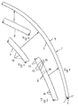
- the light guides 1 shown in FIGS. 1 and 5 are provided for lights for motor vehicles. They consist in a known manner of licht compassiondem material and are exemplified as curved rods, one end of which is formed as a light entry surface 2 (Fig. 1). It is formed by a depression in the form of a ball cutout, in which a light source 3, preferably an LED, is located. Instead of a light emitting diode, another light source, such as a light bulb or the like, may be provided.
- the convex side 4 of the light guide 1 forms a light exit side, while the opposite concave outside forms a reflection side 5. At the reflection side 5, the light beams emitted by the light source 3 are reflected to the light exit side 4.
- the reflection side 5 has differently profiled profiles or profile sections 6 to 8 over its length, the embodiments of which are shown in greater detail in FIGS. 2 to 4 and 6 to 9, respectively.
- the light guide 1 can also be designed so that the light source 3, in particular the LED, is encapsulated by the material of the light guide 1. In this case, the corresponding end of the light guide 1 does not form a light entry surface 2, since the light emerges from the light source 3 within the light guide 1.
- light guides 1 with light entry surfaces 2 will be described. The described embodiments of the light guide 1 but also apply to embodiments in which the light-emitting means 3 is encapsulated by the material of the light guide 1.
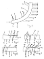
- the profile sections 6 to 8 are formed by individual prisms 11 closing together in the longitudinal direction of the light guide 1;
- other reflection or scattering bodies may be provided instead of the prisms.
- they differ the prisms of the light guide profile sections 6 to 8, for example, by their prism height, base width, asymmetry or inclination of their side surfaces 12, 13, the rounding of their edges 14 or the geometry of Einkuppelstellen. All or only some of these parameters may differ.
- the position of the light source 3 with respect to the reflective body or their side surfaces 12, 13 may be different.
- the profile sections are arranged and formed so that their prisms with increasing distance from the light entrance surface 2 and the light source 3 reflect the incident light stronger, so as to compensate for the increasing distance from the light source 3 decreasing light intensity of the exiting light, so that a more uniform light distribution over the length of the light guide 1 is achieved.
- a total reflector region 2 'adjoins which widens from the light entry surface 2 and whose generatrices are convexly curved.
- the rays emanating from the illuminant 3 partly strike the wall of the total reflector region 2 ', at which they are totally reflected.
- the side surfaces 12, 13 may be rounded or over edges 14 into each other.
- at least the prism height of the prisms 11 preferably increases with increasing distance from the luminous means 3 or the light entry surface 2.
- the prisms 11 are even more pronounced than in the profile section 6.
- the prisms 11 have a greater prism height and smaller base width with increasing distance from the light entry side 2 and with increasing distance from the profile section 6, so that their side surfaces 12, 13 at a smaller acute angle to each other than in the profile section 6.
- the prism height In the region of the profile section. 8 increases the prism height further.
- the base range may continue to decline. It is also possible to leave the base width unchanged.
- asymmetrically formed prisms 11 may be present. Such asymmetrically shaped prisms, which are for example inclined away from or towards the light entry surface 2, are shown in FIGS. 6 to 9, as will be explained below.
- the prisms 11 may be formed with sharp or rounded edges. Due to the more pronounced with increasing distance from the light entry surface 2 profiling of the reflection side 5, the decreasing light intensity and luminance in this direction can be increased by increasing the proportion of the reflection surfaces 12, 13 of the profile sections 6 to 8 on the entire reflection surface.
- successive prisms 11 can also have significantly different heights, inclinations and / or edge formations.
- the prism height increases with increasing distance from the light entrance side 2 and the low base width and sharp free edges 14 and a sharp-edged Groove 15 have.
- the relatively high prisms 11 then go into less high prisms 11, the same base width and their side surfaces 12, 13 have different heights.
- the reflection side 5 has an asymmetrical profile, whereby a respective optimal luminance distribution is achieved and the outcoupling direction for the emerging light can be set arbitrarily depending on the geometry ratios of the light guide. In this embodiment, this is achieved by the function-controlled prism height.
- Fig. 7 shows again a profile section of the reflection side 5, in which the prisms 11 are formed differently by a function-controlled Prismenrundung is used.
- the prisms In a first area, the prisms have 11, similar to those in FIG. 6, a sharp-edged transition and partially differently long side surfaces 12, 13, while in a subsequent section, the prisms 11 provided there have a lower prism height, but in their base region or groove base 15 are part-circularly rounded.
- Fig. 8 shows a profile section with function-controlled prism tilt.
- the prisms 11 are inclined differently.
- the prisms are inclined to the left in the drawing and to the right in a right section of FIG.
- the differently long design of the prism side surfaces 12, 13 is less pronounced.
- the one prism side surfaces 12 have greater lengths than the other prism side surfaces 13.
- some prisms 11, which are approximately symmetrical, are provided in the region between the prisms 11 inclined in different directions.
- a combination of function-controlled prism parameters such as height, slope and roundness
- An area with only a very low profile height is adjoined by prisms, which have increasingly pronounced, ie larger prism height, and are of asymmetrical design.
- At this transition area then again includes a range of prisms, which have similar to the first area only small height, so are barely recognizable.
- the prisms 11 'adjoining the left-hand, slightly pronounced prism region in FIG. 9 have a rounded groove base 15, but pass over sharp edges 14 into the side surfaces 12, 13. These asymmetrically formed prisms 11 'are inclined in Fig. 9 to the right.
- This prism portion 11 ' which slopes to the right, merges into a prism portion inclined to the left, in which the prisms 11 "have a sharp-edged groove bottom 15. Their side surfaces 13 are longer than the other side surfaces 12. In the connection region to the prisms 11', the prisms 11 "larger prism height, which then decreases to the right in Fig. 9. The transitions between the different prism areas take advantage of flowing, but may also be erratic in corresponding applications.
- any modifications of the prism shape and arrangement are conceivable by changing the prism height, inclination, roundness, step width, etc.
- other reflection bodies may be provided.
- the light distribution and luminous intensity or luminance can be improved so that the light guide 1 emits light evenly.
- the proportion of the reflection surface on the total reflection surface is greater there than in the light entry region.
- the embodiments described are not intended to be limiting, but are intended to illustrate that by targeted control of optical fiber parameters, such as prism height and base width, prism asymmetry (inclination) and prism edge radii, cross-sectional or coupling-geometry, light source position and the like, an adaptation to the desired Purpose is possible.
- the different configurations of the prisms can be achieved by suitable function distributions, such as higher-order polynomials, trigonometric functions, exponential functions and / or other continuous or discontinuous functions and combinations of these functions.
- suitable function distributions such as higher-order polynomials, trigonometric functions, exponential functions and / or other continuous or discontinuous functions and combinations of these functions.
- the generation parameters of adjacent outcoupling elements 11 vary in such a way that optimized or optimal functional distributions are achieved.
- optical fiber parameters can be varied independently of each other. Thus, only one fiber optic parameter can be changed or varied. But it is also possible to change two or more optical fiber parameters. Here, a wide variety of combinations of optical fiber parameters are possible.
- the light guides according to the invention can be used not only in lights of motor vehicles, but also in interior and exterior lighting of marker or integrator lights. There are also any free-form light conceivable, which are used for example for advertising or signaling.
- a targeted light intensity distribution, an effective Lichtauskoppelung in a prescribed solid angle range and a uniform luminance distribution along the light guide 1 with respect to different viewing positions can be adjusted.
- the Prismenbasisweite is advantageously only about 1 mm. Even at a distance of about 1.5 m, the prisms are then not resolved by the human eye.
- the light guide 1 then acts as a smooth, continuous rod.
Abstract
Description
Die Erfindung betrifft einen Lichtleiter für Leuchten, insbesondere für Leuchten von Kraftfahrzeugen, nach dem Oberbegriff des Anspruches 1.The invention relates to a light guide for lights, in particular for lights of motor vehicles, according to the preamble of
Es sind Lichtleiter bekannt, bei denen der Lichtaustrittsfläche eine Reflexionsfläche gegenüberliegt, die hintereinander angeordnete Prismen aufweist, die eine gleichbleibende, meistens symmetrische Prismenstruktur haben. Solche Lichtleiter haben den Nachteil, daß über die Länge des Lichtleiters keine gleichmäßige Leuchtdichteverteilung oder keine selektiv ausgerichtete Lichtstärkeverteilung möglich ist.There are light guides are known in which the light exit surface is opposite to a reflection surface having successively arranged prisms, which have a constant, usually symmetrical prism structure. Such light guides have the disadvantage that over the length of the light guide no uniform luminance distribution or no selectively aligned light intensity distribution is possible.
Der Erfindung liegt die Aufgabe zugrunde, einen Lichtleiter dieser Art so auszubilden, daß mit ihm in einfacher Weise eine gewünschte Leuchtdichteverteilung erreicht werden kann.The invention has for its object to form a light guide of this kind so that with him in a simple manner, a desired luminance distribution can be achieved.
Diese Aufgabe wird bei einem Lichtleiter der gattungsbildenden Art erfindungsgemäß mit den kennzeichnenden Merkmalen des Anspruches 1 gelöst.This object is achieved in a light guide of the generic type according to the invention with the characterizing features of
Infolge der erfindungsgemäßen Ausbildung kann eine gewünschte Leuchtdichteverteilung einfach erhalten werden. Durch entsprechende Einstellung der Größe der Reflexionsflächen wird erreicht, daß z.B. im Bereich neben der Lichtquelle der Anteil an Reflexionsflächen geringer oder größer ist als in einem entfernteren Bereich. Da im Bereich der Lichtquelle die Lichtstärke hoch ist, genügt ein verhältnismäßig kleiner Anteil an Reflexionsfläche. Die weiter entfernt von der Lichtquelle liegenden Reflexionsflächen sind prozentual in einem größeren Anteil vorhanden, um den geringeren Lichtanteil zur Auskoppelseite des Lichtleiters zu reflektieren. Auf diese Weise kann beispielsweise über die Länge der Auskoppelseite des Lichtleiters eine zumindest annähernd gleiche Leuchtdichteverteilung des abgestrahlten Lichtes erhalten werden. Es kann aber auch durch entsprechende Aufteilung des Anteils der Reflexionsflächen erreicht werden, daß das Licht über die Länge der Auskoppelseite des Lichtleiters in bestimmten Leuchtdichten austritt. Insbesondere kann infolge der erfindungsgemäßen Ausbildung das Licht gezielt so gelenkt werden, daß eine effektive Lichtauskoppelung in einem vorgeschriebenen Raumwinkelbereich erreicht wird. Dadurch wird eine gleichmäßigere mittlere Leuchtdichteverteilung entlang des Lichtleiters bezüglich verschiedener Beobachtungspositionen erreicht. Auch eine gesetzlich geforderte Lichtstärkeverteilung läßt sich auf diese Weise einfach erreichen.As a result of the construction according to the invention, a desired luminance distribution can be easily obtained. By adjusting the size of the reflection surfaces is achieved that, for example, in the area next to the light source, the proportion of reflection surfaces is less than or greater than in a more remote area. Since the light intensity is high in the region of the light source, a relatively small proportion of reflection surface is sufficient. The more distant from the light source reflection surfaces are present in percentage in a larger proportion to the lower proportion of light to Outcoupling side of the light guide to reflect. In this way, for example over the length of the coupling-out side of the light guide, an at least approximately equal luminance distribution of the emitted light can be obtained. However, it can also be achieved by appropriate division of the proportion of the reflection surfaces that the light emerges over the length of the coupling-out side of the light guide in certain luminances. In particular, as a result of the inventive design, the light can be specifically directed so that an effective Lichtauskoppelung is achieved in a prescribed solid angle range. As a result, a more uniform average luminance distribution along the light guide with respect to different viewing positions is achieved. Even a legally required light intensity distribution can be easily achieved in this way.
Die Reflexionsstruktur wird vorteilhaft durch Prismen gebildet. Um eine gleichmäßige Leuchtdichteverteilung bei gleichzeitigem Erfüllen der Anforderungen bezüglich der Lichtstärkeverteilung zu erreichen, wird eine Funktionssteuerung verschiedener Prismenparameter vorgenommen. So können die Prismenparameter örtlich variiert werden.The reflection structure is advantageously formed by prisms. In order to achieve a uniform luminance distribution while at the same time meeting the requirements with respect to the luminous intensity distribution, a function control of different prism parameters is undertaken. Thus, the prism parameters can be varied locally.
Weitere Merkmale der Erfindung ergeben sich aus den weiteren Ansprüchen, der Beschreibung und den Zeichnungen.Further features of the invention will become apparent from the other claims, the description and the drawings.
Die Erfindung wird nachstehend anhand zweier in den Zeichnungen dargestellter Ausführungsbeispiele näher beschrieben. Es zeigt:
- Fig. 1
- einen Teil eines erfindungsgemäßen Lichtleiters in Draufsicht,
- Fig. 2 bis Fig. 4
- jeweils einen Lichtleiterabschnitt gemäß Fig. 1 in vergrößerter Darstellung,
- Fig. 5
- eine zweite Ausführungsform eines erfindungsgemäßen Lichtleiters in einer Darstellung entsprechend Fig. 1,
- Fig. 6 bis Fig. 9
- jeweils unterschiedliche Ausführungsformen von Lichtleiterabschnitten des Lichtleiters.
- Fig. 1
- a part of a light guide according to the invention in plan view,
- Fig. 2 to Fig. 4
- each an optical fiber section of FIG. 1 in an enlarged view,
- Fig. 5
- a second embodiment of a light guide according to the invention in a representation corresponding to FIG. 1,
- FIG. 6 to FIG. 9
- each different embodiments of optical fiber sections of the optical fiber.
Die in den Fig. 1 und 5 dargestellten Lichtleiter 1 sind für Leuchten für Kraftfahrzeuge vorgesehen. Sie bestehen in bekannter Weise aus lichtleitendem Material und sind beispielhaft als gekrümmte Stäbe ausgebildet, deren eines Ende als Lichteintrittsfläche 2 (Fig. 1) ausgebildet ist. Sie wird durch eine Vertiefung in Form eines Kugelausschnittes gebildet, in der ein Leuchtmittel 3, vorzugsweise eine LED, liegt. Anstelle einer Leuchtdiode kann auch ein anderes Leuchtmittel, wie beispielsweise eine Glühlampe oder dergleichen, vorgesehen sein. Die konvexe Seite 4 des Lichtleiters 1 bildet eine Lichtaustrittseite, während die gegenüberliegende konkave Außenseite eine Reflexionsseite 5 bildet. An der Reflexionsseite 5 werden die vom Leuchtmittel 3 ausgesandten Lichtstrahlen zur Lichtaustrittsseite 4 reflektiert. Die Reflexionsseite 5 weist über ihre Länge unterschiedlich ausgebildete Profilierungen bzw. Profilabschnitte 6 bis 8 auf, deren Ausbildungen in den Fig. 2 bis 4 bzw. 6 bis 9 näher dargestellt sind.The
Der Lichtleiter 1 kann auch so ausgebildet sein, daß das Leuchtmittel 3, insbesondere die LED, vom Material des Lichtleiters 1 umspritzt ist. In diesem Fall bildet das entsprechende Ende des Lichtleiters 1 keine Lichteintrittsfläche 2, da das Licht innerhalb des Lichtleiters 1 aus dem Leuchtmittel 3 austritt. Im folgenden werden Lichtleiter 1 mit Lichteintrittsflächen 2 beschreiben. Die beschriebenen Ausbildungen der Lichtleiter 1 gelten aber auch für Ausführungsformen, bei denen das Leuchtmittel 3 vom Material des Lichtleiters 1 umspritzt ist.The
In den Ausführungsbeispielen sind die Profilabschnitte 6 bis 8 durch einzelne, in Längsrichtung des Lichtleiters 1 aneinanderschließende Prismen 11 gebildet; selbstverständlich können anstelle der Prismen auch andere Reflexions- bzw. Streukörper vorgesehen sein. Vorzugsweise unterscheiden sich die Prismen der Lichtleiter-Profilabschnitte 6 bis 8 beispielsweise durch ihre Prismenhöhe, Basisweite, Asymmetrie bzw. Neigung ihrer Seitenflächen 12, 13, der Abrundung ihrer Kanten 14 oder der Geometrie der Einkuppelstellen. Alle oder nur einzelne dieser Parameter können voneinander abweichen. Außerdem kann die Lage der Lichtquelle 3 in bezug auf die Reflexisionskörper bzw. ihre Seitenflächen 12, 13 unterschiedlich sein. Bei sämtlichen Ausführungsformen sind die Profilabschnitte so angeordnet und ausgebildet, daß ihre Prismen mit zunehmender Entfernung von der Lichteintrittsfläche 2 bzw. vom Leuchtmittel 3 das auftreffende Licht stärker reflektieren, um so die in zunehmender Entfernung vom Leuchtmittel 3 sich verringernde Lichtintensität des austretenden Lichtes auszugleichen, so daß eine gleichmäßigere Lichtverteilung über die Länge des Lichtleiters 1 erreicht wird.In the exemplary embodiments, the
An die Lichteintrittsfläche 2 schließt ein Totalreflektorbereich 2' an, der sich von der Lichteintrittsfläche 2 aus erweitert und dessen Mantellinien konvex gekrümmt sind. Die vom Leuchtmittel 3 ausgehenden Strahlen treffen teilweise auf die Wandung des Totalreflektorbereiches 2', an der sie total reflektiert werden. Der Bereich 2' geht in einen Profilabschnitt 6 über (Fig. 2), der eine wellenförmige Profilierung mit schwach ausgeprägten Prismen aufweist, die also geringe Prismenhöhe haben und deren Seitenflächen 12, 13 mit relativ großem stumpfen Winkel zueinander verlaufen, so daß die Basisweite dieser Prismen 11 entsprechend groß ist. Die Seitenflächen 12, 13 können abgerundet oder auch über Kanten 14 ineinander übergehen. Vorzugsweise nimmt auch innerhalb dieses Profilabschnittes 6 zumindest die Prismenhöhe der Prismen 11 mit zunehmender Entfernung vom Leuchtmittel 3 bzw. der Lichteintrittsfläche 2 zu.At the
Im Bereich des Profilabschnittes 7 gemäß Fig. 3 sind die Prismen 11 noch stärker ausgeprägt als im Profilabschnitt 6. Die Prismen 11 haben mit zunehmender Entfernung von der Lichteintrittsseite 2 und mit zunehmendem Abstand vom Profilabschnitt 6 eine größere Prismenhöhe und kleinere Basisweite, so daß ihre Seitenflächen 12, 13 unter kleinerem spitzen Winkel zueinander liegen als im Profilabschnitt 6. Im Bereich des Profilabschnittes 8 nimmt die Prismenhöhe weiter zu. Auch die Basisweite kann weiter abnehmen. Es ist auch möglich, die Basisweite unverändert zu lassen.In the region of the
In allen Profilabschnitten 6 bis 8 können auch asymmetrisch ausgebildete Prismen 11 vorhanden sein. Solche asymmetrisch ausgebildete Prismen, die zum Beispiel von der Lichteintrittsfläche 2 weg oder zu dieser hingeneigt sind, sind in den Fig. 6 bis 9 dargestellt, wie noch erläutert wird. Außerdem können die Prismen 11 mit scharfen oder auch abgerundeten Kanten ausgebildet sein. Durch die mit zunehmendem Abstand von der Lichteintrittsfläche 2 stärker ausgeprägte Profilierung der Reflexionsseite 5 kann die in dieser Richtung abnehmende Lichtstärke und Leuchtdichte durch eine Erhöhung des Anteils der Reflexionsflächen 12, 13 der Profilabschnitte 6 bis 8 an der gesamten Reflexionsfläche erhöht werden.In all
Wie die Fig. 5 bis 9 zeigen, können aufeinanderfolgende Prismen 11 auch deutlich unterschiedliche Höhen, Neigungen und/oder Kantenausbildungen haben.As shown in FIGS. 5 to 9,
Wie Fig. 6 zeigt, schließen an einen Bereich 9 mit Prismen geringer Höhe, ähnlich der gemäß Fig. 2 Prismen 11 an, deren Prismenhöhe mit zunehmendem Abstand von der Lichteintrittsseite 2 stark zunimmt und die geringe Basisweite sowie scharfe freie Kanten 14 und einen scharfkantig ausgebildeten Nutgrund 15 aufweisen. Die relativ hohen Prismen 11 gehen dann in weniger hohe Prismen 11 über, die gleiche Basisweite und deren Seitenflächen 12, 13 unterschiedliche Höhe haben. In diesem Profilbereich hat die Reflexionsseite 5 einen asymmetrischen Verlauf, wodurch eine jeweils optimale Leuchtdichteverteilung erreicht und die Auskopplungsrichtung für das austretende Licht je nach Geometrieverhältnissen des Lichtleiters beliebig eingestellt werden können. Bei dieser Ausführung wird dies durch die funktionsgesteuerte Prismenhöhe erreicht.As shown in FIG. 6, close to a region 9 with prisms of low height, similar to that of FIG. 2
Fig. 7 zeigt wieder einen Profilabschnitt der Reflexionsseite 5, bei dem die Prismen 11 unterschiedlich ausgebildet sind, indem eine funktionsgesteuerte Prismenrundung eingesetzt wird. In einem ersten Bereich haben die Prismen 11 ähnlich denen in Fig. 6 einen scharfkantigen Übergang und teilweise unterschiedlich lange Seitenflächen 12, 13, während in einem anschließenden Abschnitt die dort vorgesehenen Prismen 11 geringere Prismenhöhe haben, jedoch in ihrem Basisbereich bzw. Nutgrund 15 teilkreisförmig abgerundet sind.Fig. 7 shows again a profile section of the
Fig. 8 zeigt einen Profilabschnitt mit funktionsgesteuerter Prismenneigung. In diesem Profilabschnitt sind die Prismen 11 unterschiedlich geneigt. In einem ersten Abschnitt sind die Prismen in der Zeichnung nach links und in einem rechten Abschnitt der Fig. 8 nach rechts geneigt. Bei den dazwischen liegenden Prismen 11 ist die unterschiedlich lange Ausbildung der Prismenseitenflächen 12, 13 weniger stark ausgeprägt. Bei dem linken Abschnitt haben die einen Prismenseitenflächen 12 größere Länge als die anderen Prismenseitenflächen 13. Im Bereich zwischen den in unterschiedlichen Richtungen geneigten Prismen 11 sind im Ausführungsbeispiel einige Prismen 11 vorgesehen, die etwa symmetrisch ausgebildet sind.Fig. 8 shows a profile section with function-controlled prism tilt. In this profile section, the
Bei der Ausführungsform nach Fig. 9 wird eine Kombination funktionsgesteuerter Prismenparameter, wie Höhe, Neigung und Rundung, eingesetzt. An einen Bereich mit nur sehr geringer Profilhöhe schließen Prismen an, die zunehmend ausgeprägter, also größere Prismenhöhe haben und asymmetrisch ausgebildet sind. An diesen Übergangsbereich schließt dann wieder ein Bereich mit Prismen an, die ähnlich wie im ersten Bereich nur geringe Höhe haben, also kaum erkennbar sind. Die an den in Fig. 9 linken, schwach ausgeprägten Prismenbereich anschließenden Prismen 11' haben einen abgerundeten Nutgrund 15, gehen aber über scharfe Kanten 14 in die Seitenflächen 12, 13 über. Diese asymmetrisch ausgebildeten Prismen 11' sind in Fig. 9 nach rechts geneigt. Dieser nach rechts geneigte Prismenteil 11' geht in einen nach links geneigten Prismenabschnitt über, in dem die Prismen 11" einen scharfkantigen Nutgrund 15 haben. Ihre Seitenflächen 13 sind länger als die anderen Seitenflächen 12. Im Anschlußbereich an die Prismen 11' haben die Prismen 11" größere Prismenhöhe, die dann nach rechts in Fig. 9 abnimmt. Die Übergänge zwischen den unterschiedlichen Prismenbereichen erfolgen vorteilhaft fließend, können aber bei entsprechenden Anwendungsfällen auch sprunghaft sein.In the embodiment of Fig. 9, a combination of function-controlled prism parameters, such as height, slope and roundness, is used. An area with only a very low profile height is adjoined by prisms, which have increasingly pronounced, ie larger prism height, and are of asymmetrical design. At this transition area then again includes a range of prisms, which have similar to the first area only small height, so are barely recognizable. The prisms 11 'adjoining the left-hand, slightly pronounced prism region in FIG. 9 have a rounded
Selbstverständlich sind beliebige, durch Ändern der Prismenhöhe, -neigung, -rundung, -schrittweite usw. Abwandlungen der Prismenform und Anordnung denkbar. Anstelle der Prismen können, wie bereits erwähnt, auch andere Reflexionskörper vorgesehen sein. Durch entsprechende Ausbildung und Anordnung dieser Reflexionskörper kann die Lichtverteilung und Lichtstärke bzw. Leuchtdichte so verbessert werden, daß der Lichtleiter 1 gleichmäßig Licht abstrahlt. In jedem Fall ist der Anteil der Reflexionsfläche des Lichtleiters 1 in seinem an die Lichteintrittsfläche 2 anschließenden Teil, bezogen auf die Gesamtreflexionsfläche des Lichtleiters 1, kleiner als in den übrigen Bereichen. Damit in den weiter entfernt von der Lichteintrittsseite 2 bzw. vom Leuchtmittel 3 liegenden Bereichen trotz abnehmender Leuchtdichte ausreichend Licht nach außen abgestrahlt wird, ist dort der Anteil der Reflexionsfläche an der Gesamtreflexionsfläche größer als im Lichteintrittsbereich.Of course, any modifications of the prism shape and arrangement are conceivable by changing the prism height, inclination, roundness, step width, etc. Instead of the prisms, as already mentioned, other reflection bodies may be provided. By appropriate design and arrangement of these reflection body, the light distribution and luminous intensity or luminance can be improved so that the
Die beschriebenen Ausführungsbeispiele sind nicht beschränkend zu verstehen, sondern sollen veranschaulichen, daß durch gezielte Steuerung von Lichtleiterparametern, wie Prismenhöhe und -basisweite, Prismenasymmetrie (-neigung) und Prismenkantenradien, Querschnitts- oder Einkoppelstellen-Geometrie, Lichtquellenposition und dergleichen, eine Anpassung an den gewünschten Einsatzzweck möglich ist. Die unterschiedlichen Gestaltungen der Prismen lassen sich durch geeignete Funktionsverteilungen erreichen, wie zum Beispiel Polynome höheren Grades, Trigonometriefunktionen, Exponentialfunktionen und/oder andere kontinuierliche oder diskontinuierliche Funktionen sowie Kombinationen dieser Funktionen. Dadurch wird die Lichtstärke- und Leuchtdichteverteilung besser an vorgegebene Anforderungen angepaßt, insbesondere werden Lichtauskoppelungseffizienz und Wahrnehmung und ihre Wirkung gezielt verbessert.The embodiments described are not intended to be limiting, but are intended to illustrate that by targeted control of optical fiber parameters, such as prism height and base width, prism asymmetry (inclination) and prism edge radii, cross-sectional or coupling-geometry, light source position and the like, an adaptation to the desired Purpose is possible. The different configurations of the prisms can be achieved by suitable function distributions, such as higher-order polynomials, trigonometric functions, exponential functions and / or other continuous or discontinuous functions and combinations of these functions. As a result, the luminous intensity and luminance distribution is better adapted to given requirements, in particular Lichtauskoppelungseffizienz and perception and their effect are specifically improved.
Die Erzeugungsparameter benachbarter Auskopplungselemente 11 variieren so, daß optimierte bzw. optimale Funktionsverteilungen erreicht werden.The generation parameters of adjacent
Die beschriebenen Lichtleiterparameter können unabhängig voneinander variiert werden. So kann nur ein Lichtleiterparameter geändert bzw. variiert werden. Es ist aber auch möglich, zwei oder mehr Lichtleiterparameter zu verändern. Hierbei sind unterschiedlichste Kombinationen von Lichtleiterparametern möglich.The described optical fiber parameters can be varied independently of each other. Thus, only one fiber optic parameter can be changed or varied. But it is also possible to change two or more optical fiber parameters. Here, a wide variety of combinations of optical fiber parameters are possible.
Die erfindungsgemäßen Lichtleiter können nicht nur bei Leuchten von Kraftfahrzeugen, sondern auch bei Innen- und Außenbeleuchtungen von Markierungs- oder Integratorleuchten eingesetzt werden. Es sind auch beliebige Freiformlichtleiter denkbar, die beispielsweise für die Werbung oder Signalisation eingesetzt werden.The light guides according to the invention can be used not only in lights of motor vehicles, but also in interior and exterior lighting of marker or integrator lights. There are also any free-form light conceivable, which are used for example for advertising or signaling.
Wie sich aus den beschriebenen Ausführungsbeispielen ergibt, können eine gezielte Lichtstärkeverteilung, eine effektive Lichtauskoppelung in einem vorgeschriebenen Raumwinkelbereich und eine gleichmäßige Leuchtdichteverteilung entlang des Lichtleiters 1 bezüglich verschiedener Beobachtungspositionen eingestellt werden.As is apparent from the described embodiments, a targeted light intensity distribution, an effective Lichtauskoppelung in a prescribed solid angle range and a uniform luminance distribution along the
Die Prismenbasisweite liegt vorteilhaft bei nur etwa 1 mm. Schon bei einem Abstand von etwa 1,5 m sind die Prismen dann vom menschlichen Auge nicht aufzulösen. Der Lichtleiter 1 wirkt dann wie ein glatter, durchgehender Stab.The Prismenbasisweite is advantageously only about 1 mm. Even at a distance of about 1.5 m, the prisms are then not resolved by the human eye. The
Claims (14)
dadurch gekennzeichnet, daß der Anteil an Reflexionsfläche (12, 13) eines der Lichtquelle (3) näher liegenden Bereiches (6 bis 8) der Reflexionsstruktur an der Gesamtreflexionsfläche des Lichtleiters (1) kleiner oder größer ist als der Anteil der Reflexionsfläche (12, 13) eines von der Lichtquelle (3) weiter entfernt liegenden Bereiches.Light guide for lights, preferably for lights of motor vehicles, with at least one light source whose radiated light is deflected out of the light guide by a reflection structure over at least part of the length at a light exit side,
characterized in that the proportion of the reflection surface (12, 13) of the light source (3) nearer area (6 to 8) of the reflection structure on the total reflection surface of the light guide (1) is smaller or larger than the proportion of the reflection surface (12, 13 ) of the light source (3) further away area.
dadurch gekennzeichnet, daß der Anteil an Reflexionsfläche (12,13) stetig zunimmt.Optical fiber according to claim 1,
characterized in that the proportion of reflection surface (12,13) steadily increases.
dadurch gekennzeichnet, daß der Anteil an Reflexionsfläche (12,13) abschnittsweise zunimmt.Optical fiber according to claim 1,
characterized in that the proportion of reflection surface (12,13) increases in sections.
dadurch gekennzeichnet, daß der Anteil an Reflexionsfläche (12, 13) in einem Abschnitt (6 bis 8) des Lichtleiters (1) zunimmt.Optical fiber according to one of claims 1 to 3,
characterized in that the proportion of reflection surface (12, 13) in a portion (6 to 8) of the light guide (1) increases.
dadurch gekennzeichnet, daß die Reflexionsstruktur durch Prismen (11) gebildet ist, die vorteilhaft unterschiedliche Querschnittsform haben.Optical fiber according to one of claims 1 to 4,
characterized in that the reflection structure is provided by prisms (11) is formed, which advantageously have different cross-sectional shape.
dadurch gekennzeichnet, daß die Prismen (11), die näher bei der Lichtquelle (3) liegen, kleinere Reflexionsfläche (12, 13) haben als die größeren Abstand von der Lichtquelle aufweisenden Prismen.Optical fiber according to claim 5,
characterized in that the prisms (11) closer to the light source (3) have a smaller reflecting surface (12, 13) than the larger prisms spaced from the light source.
dadurch gekennzeichnet, daß die Reflexionsfläche (12, 13) benachbarter Prismen (11) mit zunehmendem Abstand von der Lichtquelle (3) zunimmt.Optical fiber according to claim 5 or 6,
characterized in that the reflection surface (12, 13) of adjacent prisms (11) increases with increasing distance from the light source (3).
dadurch gekennzeichnet, daß die Prismen (11, 11', 11 ") innerhalb eines Bereiches (6 bis 8) des Lichtleiters (1) gleich große Reflexionsflächen (12, 13) haben, und daß die Größe der Reflexionsflächen (12, 13) benachbarter Bereiche (6 bis 8) unterschiedlich ist.Optical fiber according to one of claims 5 to 7,
characterized in that the prisms (11, 11 ', 11 ") within a range (6 to 8) of the light guide (1) have the same size reflection surfaces (12, 13), and that the size of the reflection surfaces (12, 13) adjacent Areas (6 to 8) is different.
dadurch gekennzeichnet, daß sich die Prismen (11, 11', 11 ") hinsichtlich ihrer Höhe und/oder ihrer Basisweite und/oder Asymmetrie und/oder Neigung und/oder Kantenradien voneinander unterscheiden.Optical fiber according to one of claims 5 to 8,
characterized in that the prisms (11, 11 ', 11 ") differ from each other in terms of their height and / or their base width and / or asymmetry and / or inclination and / or edge radii.
dadurch gekennzeichnet, daß einander benachbarte Reflexionsflächen (12, 13) spitzwinklig und/oder abgerundet ineinander übergehen.Optical fiber according to one of claims 5 to 9,
characterized in that adjacent reflecting surfaces (12, 13) at an acute angle and / or rounded into one another.
dadurch gekennzeichnet, daß die Prismen (11, 11', 11") in gleicher und/oder entgegengesetzter Richtung zueinander geneigt sind.Optical fiber according to one of claims 5 to 10,
characterized in that the prisms (11, 11 ', 11 ") are inclined in the same and / or opposite direction to each other.
dadurch gekennzeichnet, daß die Prismen (11, 11', 11") symmetrische Querschnittsform haben.Optical fiber according to one of claims 5 to 11,
characterized in that the prisms (11, 11 ', 11 ") are symmetrical Have cross-sectional shape.
dadurch gekennzeichnet, daß die Prismen (11, 11', 11") asymmetrische Querschnittsform haben.Optical fiber according to one of claims 5 to 11,
characterized in that the prisms (11, 11 ', 11 ") have asymmetrical cross-sectional shape.
dadurch gekennzeichnet, daß die Parameter der Prismen (11, 11', 11") funktionsgesteuert gewählt werden.Optical fiber according to one of claims 5 to 13,
characterized in that the parameters of the prisms (11, 11 ', 11 ") is operatively controlled to be selected.
Applications Claiming Priority (1)
| Application Number | Priority Date | Filing Date | Title |
|---|---|---|---|
| DE102004046386A DE102004046386A1 (en) | 2004-09-24 | 2004-09-24 | Light guide for lights, in particular for lights of motor vehicles |
Publications (3)
| Publication Number | Publication Date |
|---|---|
| EP1640656A2 true EP1640656A2 (en) | 2006-03-29 |
| EP1640656A3 EP1640656A3 (en) | 2007-02-28 |
| EP1640656B1 EP1640656B1 (en) | 2012-10-31 |
Family
ID=35159769
Family Applications (1)
| Application Number | Title | Priority Date | Filing Date |
|---|---|---|---|
| EP05019603A Active EP1640656B1 (en) | 2004-09-24 | 2005-09-09 | Light guides for lamps, expecially for vehicular lamps |
Country Status (4)
| Country | Link |
|---|---|
| US (1) | US20060067084A1 (en) |
| EP (1) | EP1640656B1 (en) |
| KR (1) | KR20060051293A (en) |
| DE (1) | DE102004046386A1 (en) |
Cited By (4)
| Publication number | Priority date | Publication date | Assignee | Title |
|---|---|---|---|---|
| EP1780463A1 (en) * | 2005-10-27 | 2007-05-02 | Valeo Vision | Lighting assembly for vehicles comprising a light guide |
| NL1036759C2 (en) * | 2009-03-24 | 2010-09-27 | Spanninga Metaal | REAR WHEEL AND BACKLIGHT FOR A REAR WHEEL. |
| EP2662713A1 (en) * | 2012-05-07 | 2013-11-13 | Hella KGaA Hueck & Co. | Illumination device for vehicles |
| EP2108883A3 (en) * | 2008-03-27 | 2013-12-18 | Hella KGaA Hueck & Co. | Signal light for motor vehicles |
Families Citing this family (36)
| Publication number | Priority date | Publication date | Assignee | Title |
|---|---|---|---|---|
| US20080310187A1 (en) * | 2006-06-28 | 2008-12-18 | Yujing Technology Co., Ltd. | Light guide device for vehicle lamps |
| DE102006051060A1 (en) * | 2006-10-30 | 2008-05-08 | Bayerische Motoren Werke Ag | vehicle headlights |
| DE102006051059A1 (en) * | 2006-10-30 | 2008-05-08 | Bayerische Motoren Werke Ag | vehicle headlights |
| DE102006051058A1 (en) * | 2006-10-30 | 2008-05-08 | Bayerische Motoren Werke Ag | vehicle headlights |
| DE102006062272A1 (en) | 2006-12-22 | 2008-06-26 | Bayerische Motoren Werke Ag | Motor vehicle light i.e. tail lamp, has expanding unit expanding opening angle of incident light beam, and deflection unit arranged behind rear side of light conductor for deflecting incident light beam |
| JP2009218076A (en) * | 2008-03-10 | 2009-09-24 | Koito Mfg Co Ltd | Vehicular lighting fixture |
| US8070341B2 (en) * | 2008-12-18 | 2011-12-06 | Visteon Global Technologies, Inc. | Light pipe with uniformly lit appearance |
| US8057081B2 (en) * | 2009-02-11 | 2011-11-15 | GM Global Technology Operations LLC | Light guide for vehicle lamp assembly |
| DE102009027792B4 (en) * | 2009-07-17 | 2012-11-08 | Lisa Dräxlmaier GmbH | Lighting device with a light guide and interior trim part for a vehicle with such a lighting device |
| DE102009038523A1 (en) | 2009-08-25 | 2011-03-10 | Odelo Gmbh | Lamp and light |
| DE102009052339A1 (en) * | 2009-11-03 | 2011-05-05 | Automotive Lighting Reutlingen Gmbh | Lighting device for a motor vehicle |
| US9134474B2 (en) * | 2010-03-16 | 2015-09-15 | Toyota Motor Engineering & Manufacturing North America, Inc. | Headlamp bulb type light pipe |
| US8870423B2 (en) * | 2011-05-19 | 2014-10-28 | Stanley Electric Co., Ltd. | Vehicle decorative lighting device and vehicle lamp |
| JP5749576B2 (en) * | 2011-06-07 | 2015-07-15 | 株式会社小糸製作所 | Vehicle lighting |
| FR2977332B1 (en) * | 2011-06-29 | 2017-08-11 | Valeo Vision | LIGHT GUIDE WITH DECOUPLING PORTION AND COVER RECLAIMING DECAYED RAYS |
| EP2543540A1 (en) * | 2011-07-07 | 2013-01-09 | Odelo GmbH | Optical fibre, illuminant and motor vehicle light |
| JP5779045B2 (en) * | 2011-08-25 | 2015-09-16 | スタンレー電気株式会社 | Vehicle lighting |
| JP2013109942A (en) * | 2011-11-21 | 2013-06-06 | Koito Mfg Co Ltd | Vehicular lamp |
| US9690392B2 (en) | 2012-10-15 | 2017-06-27 | Sony Corporation | Operating device including a touch sensor |
| KR102249208B1 (en) * | 2012-10-15 | 2021-05-10 | 주식회사 소니 인터랙티브 엔터테인먼트 | Control deⅵce |
| BR112015029325B1 (en) * | 2013-05-28 | 2022-01-11 | Honda Motor Co., Ltd. | VEHICLE LAMP |
| KR102064342B1 (en) * | 2013-08-06 | 2020-01-09 | 현대모비스 주식회사 | Light source and lamp for vehicle having the same |
| CN103591523A (en) * | 2013-10-19 | 2014-02-19 | 宜兰汽车配件制造(平湖)有限公司 | Automotive armrest decoration strip lamp |
| AT515470A1 (en) * | 2014-03-04 | 2015-09-15 | Zizala Lichtsysteme Gmbh | Light coupling protection between light functions |
| FR3024529B1 (en) * | 2014-07-30 | 2016-09-02 | Valeo Vision Belgique | LIGHT MODULE WITH OPTICAL GUIDE FOR MOTOR VEHICLE |
| JP2016046120A (en) * | 2014-08-25 | 2016-04-04 | スタンレー電気株式会社 | Vehicular lighting fixture |
| JP2016119273A (en) * | 2014-12-24 | 2016-06-30 | 株式会社小糸製作所 | Vehicular lighting fixture |
| KR102288453B1 (en) | 2015-02-25 | 2021-08-10 | 현대모비스 주식회사 | Lamp apparatus for an automobile |
| EP3132955B1 (en) * | 2015-07-28 | 2020-04-08 | Inalfa Roof Systems Group B.V. | Rollo assembly and open roof construction for a vehicle provided therewith |
| US10330902B1 (en) | 2017-06-16 | 2019-06-25 | Dbm Reflex Enterprises Inc. | Illumination optics and devices |
| CN108627911B (en) * | 2018-05-15 | 2024-04-05 | 杭州矽能新材料有限公司 | Special-shaped light guide part and luminous decoration assembly |
| KR102510943B1 (en) * | 2018-09-28 | 2023-03-16 | 에스엘 주식회사 | lamp for vehicle |
| WO2020162559A1 (en) * | 2019-02-07 | 2020-08-13 | 本田技研工業株式会社 | Calculation device and method, and program |
| DE102020121819A1 (en) | 2020-08-20 | 2022-02-24 | Daimler Ag | Arrangement for emitting light on a front side of a vehicle |
| FR3121198B1 (en) * | 2021-03-23 | 2023-04-07 | Luxor Lighting | Light guide for vehicle lighting |
| EP4191129A1 (en) * | 2021-12-02 | 2023-06-07 | ZKW Group GmbH | Light guide for vehicle |
Family Cites Families (21)
| Publication number | Priority date | Publication date | Assignee | Title |
|---|---|---|---|---|
| FR1580461A (en) * | 1968-07-11 | 1969-09-05 | ||
| DE3123369A1 (en) * | 1981-06-12 | 1983-02-03 | Vdo Schindling | Optical waveguide |
| US4765701A (en) * | 1987-01-30 | 1988-08-23 | Poly-Optical Products, Inc. | Illuminator optical fiber rod |
| EP0544332B1 (en) * | 1991-11-28 | 1997-01-29 | Enplas Corporation | Surface light source device |
| JPH06314069A (en) * | 1993-03-03 | 1994-11-08 | Fujitsu Ltd | Illuminating device |
| CA2134902C (en) * | 1994-04-07 | 2000-05-16 | Friedrich Bertignoll | Light diffusing apparatus |
| US5590945A (en) * | 1995-07-26 | 1997-01-07 | Industrial Devices, Inc. | Illuminated line of light using point light source |
| TW404532U (en) * | 1995-11-10 | 2000-09-01 | Starlite Ind | Panel for surface light source device |
| JP3588180B2 (en) * | 1995-12-28 | 2004-11-10 | 株式会社エンプラス | Light control member and side light type surface light source device |
| US6168281B1 (en) * | 1997-12-17 | 2001-01-02 | Minebea Co., Ltd. | Transparent and spread illuminating apparatus |
| DE19804440A1 (en) * | 1998-02-05 | 1999-08-12 | Hella Kg Hueck & Co | Rod-shaped light guide |
| ES2300237T5 (en) * | 1999-01-21 | 2012-03-06 | Truck-Lite Europe Gmbh | LIGHTING FOR VEH�? ASS. |
| ES2168071B1 (en) * | 2000-07-12 | 2003-07-16 | Barros Alejandro Rodriguez | MODULAR REAR VIEW MIRROR WITH INTERCHANGEABLE MULTIPLE SIGNALS FOR VEHICLES OF 2, 3, 4 OR MORE WHEELS. |
| JP3670949B2 (en) * | 2000-09-27 | 2005-07-13 | 三洋電機株式会社 | Surface light source device |
| JP2002298628A (en) * | 2001-03-30 | 2002-10-11 | Minebea Co Ltd | Flat lighting device |
| US6769798B2 (en) * | 2002-04-11 | 2004-08-03 | E'sam Co.,. Ltd. | Side mirror cover and cover lamp to be used therefor |
| US6863414B2 (en) * | 2002-12-27 | 2005-03-08 | Quanta Display Incorporation | Front light module |
| US6880960B2 (en) * | 2003-03-26 | 2005-04-19 | E'sam Co., Ltd. | Side mirror cover and side mirror body |
| DE102004015544B4 (en) * | 2003-03-31 | 2009-05-07 | Toyoda Gosei Co., Ltd. | LED light and side mirror device |
| KR101075232B1 (en) * | 2004-02-06 | 2011-10-20 | 삼성전자주식회사 | Light guide plate, backlight unit, liquid crystal display and manufacturing method of the light guide plate |
| JP4276250B2 (en) * | 2006-10-11 | 2009-06-10 | 株式会社ミツバ | Door mirror with turn lamp |
-
2004
- 2004-09-24 DE DE102004046386A patent/DE102004046386A1/en not_active Withdrawn
-
2005
- 2005-09-09 EP EP05019603A patent/EP1640656B1/en active Active
- 2005-09-14 KR KR1020050085780A patent/KR20060051293A/en not_active Application Discontinuation
- 2005-09-21 US US11/231,463 patent/US20060067084A1/en not_active Abandoned
Non-Patent Citations (1)
| Title |
|---|
| None |
Cited By (5)
| Publication number | Priority date | Publication date | Assignee | Title |
|---|---|---|---|---|
| EP1780463A1 (en) * | 2005-10-27 | 2007-05-02 | Valeo Vision | Lighting assembly for vehicles comprising a light guide |
| FR2892800A1 (en) * | 2005-10-27 | 2007-05-04 | Valeo Vision Sa | OPTICALLY GUIDED LIGHTING OR SIGNALING DEVICE FOR MOTOR VEHICLE |
| EP2108883A3 (en) * | 2008-03-27 | 2013-12-18 | Hella KGaA Hueck & Co. | Signal light for motor vehicles |
| NL1036759C2 (en) * | 2009-03-24 | 2010-09-27 | Spanninga Metaal | REAR WHEEL AND BACKLIGHT FOR A REAR WHEEL. |
| EP2662713A1 (en) * | 2012-05-07 | 2013-11-13 | Hella KGaA Hueck & Co. | Illumination device for vehicles |
Also Published As
| Publication number | Publication date |
|---|---|
| KR20060051293A (en) | 2006-05-19 |
| DE102004046386A1 (en) | 2006-04-06 |
| EP1640656B1 (en) | 2012-10-31 |
| EP1640656A3 (en) | 2007-02-28 |
| US20060067084A1 (en) | 2006-03-30 |
Similar Documents
| Publication | Publication Date | Title |
|---|---|---|
| EP1640656B1 (en) | Light guides for lamps, expecially for vehicular lamps | |
| DE102013226181B4 (en) | Optical element, as well as arrangement for light emission | |
| EP1022187B2 (en) | Vehicle light | |
| EP2754948B1 (en) | Light module for a motor vehicle headlamp, which is equipped for forming strip-shaped light distributions | |
| EP1195296A2 (en) | Direction indicating side light | |
| AT517105B1 (en) | Optical fiber arrangement for generating at least one illumination function and / or signaling function of a motor vehicle headlight | |
| EP3210827A1 (en) | Vehicle lamp | |
| DE102008048751A1 (en) | Luminaire for motor vehicles | |
| DE102004054732B4 (en) | Lichtleiteranordung | |
| EP3118060A1 (en) | Light guidance device for creating at least one illumination function and/or signaling function of a head lamp of a vehicle | |
| AT517413B1 (en) | Optical fiber arrangement for generating at least one illumination function and / or signaling function of a motor vehicle headlight | |
| DE10356483B4 (en) | Vehicle outside mirror light of a motor vehicle | |
| DE10032927A1 (en) | Lighting device e.g. for illuminating motor vehicle interior, uses plate-shaped or bar-type light-guide | |
| EP2502784B1 (en) | Vehicle light, in particular for lighting the interior of a vehicle | |
| EP1491815A2 (en) | Vehicle lighting device | |
| EP1408362A1 (en) | Lamp, in particular vehicle lamp | |
| DE10149044B4 (en) | vehicle light | |
| DE102012210444B4 (en) | Vehicle lamp with several deflecting bodies in the reflector | |
| DE10135478B4 (en) | lighting device | |
| EP1574392B1 (en) | Side flashing lamp | |
| DE10011378B4 (en) | Hollow-light luminaire with indirect light emission | |
| DE10314357A1 (en) | Car lamp, especially additional brake light with light source and clear, transparent light outlet disc, with smooth outer face and structured inner surface | |
| DE10317062A1 (en) | Linear lighting unit for vehicle, includes end-lit optical conductor rod with light exit surfaces along it, located at focal point of light deflector | |
| EP1156268B1 (en) | Light guide lamp with nonuniform refractive structure | |
| EP3412963A1 (en) | Transparent component arrangement of a light module and light module comprising such a transparent component arrangement |
Legal Events
| Date | Code | Title | Description |
|---|---|---|---|
| PUAI | Public reference made under article 153(3) epc to a published international application that has entered the european phase |
Free format text: ORIGINAL CODE: 0009012 |
|
| AK | Designated contracting states |
Kind code of ref document: A2 Designated state(s): AT BE BG CH CY CZ DE DK EE ES FI FR GB GR HU IE IS IT LI LT LU LV MC NL PL PT RO SE SI SK TR |
|
| AX | Request for extension of the european patent |
Extension state: AL BA HR MK YU |
|
| PUAL | Search report despatched |
Free format text: ORIGINAL CODE: 0009013 |
|
| AK | Designated contracting states |
Kind code of ref document: A3 Designated state(s): AT BE BG CH CY CZ DE DK EE ES FI FR GB GR HU IE IS IT LI LT LU LV MC NL PL PT RO SE SI SK TR |
|
| AX | Request for extension of the european patent |
Extension state: AL BA HR MK YU |
|
| 17P | Request for examination filed |
Effective date: 20070827 |
|
| 17Q | First examination report despatched |
Effective date: 20071002 |
|
| AKX | Designation fees paid |
Designated state(s): AT BE BG CH CY CZ DE DK EE ES FI FR GB GR HU IE IS IT LI LT LU LV MC NL PL PT RO SE SI SK TR |
|
| RAP1 | Party data changed (applicant data changed or rights of an application transferred) |
Owner name: ODELO GMBH |
|
| RAP1 | Party data changed (applicant data changed or rights of an application transferred) |
Owner name: ODELO GMBH |
|
| APBK | Appeal reference recorded |
Free format text: ORIGINAL CODE: EPIDOSNREFNE |
|
| APBN | Date of receipt of notice of appeal recorded |
Free format text: ORIGINAL CODE: EPIDOSNNOA2E |
|
| APBR | Date of receipt of statement of grounds of appeal recorded |
Free format text: ORIGINAL CODE: EPIDOSNNOA3E |
|
| APAV | Appeal reference deleted |
Free format text: ORIGINAL CODE: EPIDOSDREFNE |
|
| APBT | Appeal procedure closed |
Free format text: ORIGINAL CODE: EPIDOSNNOA9E |
|
| GRAP | Despatch of communication of intention to grant a patent |
Free format text: ORIGINAL CODE: EPIDOSNIGR1 |
|
| GRAS | Grant fee paid |
Free format text: ORIGINAL CODE: EPIDOSNIGR3 |
|
| GRAA | (expected) grant |
Free format text: ORIGINAL CODE: 0009210 |
|
| AK | Designated contracting states |
Kind code of ref document: B1 Designated state(s): AT BE BG CH CY CZ DE DK EE ES FI FR GB GR HU IE IS IT LI LT LU LV MC NL PL PT RO SE SI SK TR |
|
| REG | Reference to a national code |
Ref country code: GB Ref legal event code: FG4D Free format text: NOT ENGLISH Ref country code: CH Ref legal event code: EP |
|
| REG | Reference to a national code |
Ref country code: AT Ref legal event code: REF Ref document number: 582225 Country of ref document: AT Kind code of ref document: T Effective date: 20121115 |
|
| REG | Reference to a national code |
Ref country code: IE Ref legal event code: FG4D Free format text: LANGUAGE OF EP DOCUMENT: GERMAN |
|
| REG | Reference to a national code |
Ref country code: DE Ref legal event code: R096 Ref document number: 502005013220 Country of ref document: DE Effective date: 20121227 |
|
| REG | Reference to a national code |
Ref country code: LT Ref legal event code: MG4D |
|
| REG | Reference to a national code |
Ref country code: NL Ref legal event code: VDEP Effective date: 20121031 |
|
| PG25 | Lapsed in a contracting state [announced via postgrant information from national office to epo] |
Ref country code: NL Free format text: LAPSE BECAUSE OF FAILURE TO SUBMIT A TRANSLATION OF THE DESCRIPTION OR TO PAY THE FEE WITHIN THE PRESCRIBED TIME-LIMIT Effective date: 20121031 Ref country code: ES Free format text: LAPSE BECAUSE OF FAILURE TO SUBMIT A TRANSLATION OF THE DESCRIPTION OR TO PAY THE FEE WITHIN THE PRESCRIBED TIME-LIMIT Effective date: 20130211 Ref country code: IS Free format text: LAPSE BECAUSE OF FAILURE TO SUBMIT A TRANSLATION OF THE DESCRIPTION OR TO PAY THE FEE WITHIN THE PRESCRIBED TIME-LIMIT Effective date: 20130228 Ref country code: LT Free format text: LAPSE BECAUSE OF FAILURE TO SUBMIT A TRANSLATION OF THE DESCRIPTION OR TO PAY THE FEE WITHIN THE PRESCRIBED TIME-LIMIT Effective date: 20121031 Ref country code: SE Free format text: LAPSE BECAUSE OF FAILURE TO SUBMIT A TRANSLATION OF THE DESCRIPTION OR TO PAY THE FEE WITHIN THE PRESCRIBED TIME-LIMIT Effective date: 20121031 Ref country code: FI Free format text: LAPSE BECAUSE OF FAILURE TO SUBMIT A TRANSLATION OF THE DESCRIPTION OR TO PAY THE FEE WITHIN THE PRESCRIBED TIME-LIMIT Effective date: 20121031 |
|
| PG25 | Lapsed in a contracting state [announced via postgrant information from national office to epo] |
Ref country code: SI Free format text: LAPSE BECAUSE OF FAILURE TO SUBMIT A TRANSLATION OF THE DESCRIPTION OR TO PAY THE FEE WITHIN THE PRESCRIBED TIME-LIMIT Effective date: 20121031 Ref country code: PT Free format text: LAPSE BECAUSE OF FAILURE TO SUBMIT A TRANSLATION OF THE DESCRIPTION OR TO PAY THE FEE WITHIN THE PRESCRIBED TIME-LIMIT Effective date: 20130228 Ref country code: CY Free format text: LAPSE BECAUSE OF FAILURE TO SUBMIT A TRANSLATION OF THE DESCRIPTION OR TO PAY THE FEE WITHIN THE PRESCRIBED TIME-LIMIT Effective date: 20121031 Ref country code: PL Free format text: LAPSE BECAUSE OF FAILURE TO SUBMIT A TRANSLATION OF THE DESCRIPTION OR TO PAY THE FEE WITHIN THE PRESCRIBED TIME-LIMIT Effective date: 20121031 Ref country code: GR Free format text: LAPSE BECAUSE OF FAILURE TO SUBMIT A TRANSLATION OF THE DESCRIPTION OR TO PAY THE FEE WITHIN THE PRESCRIBED TIME-LIMIT Effective date: 20130201 Ref country code: LV Free format text: LAPSE BECAUSE OF FAILURE TO SUBMIT A TRANSLATION OF THE DESCRIPTION OR TO PAY THE FEE WITHIN THE PRESCRIBED TIME-LIMIT Effective date: 20121031 |
|
| PG25 | Lapsed in a contracting state [announced via postgrant information from national office to epo] |
Ref country code: DK Free format text: LAPSE BECAUSE OF FAILURE TO SUBMIT A TRANSLATION OF THE DESCRIPTION OR TO PAY THE FEE WITHIN THE PRESCRIBED TIME-LIMIT Effective date: 20121031 Ref country code: SK Free format text: LAPSE BECAUSE OF FAILURE TO SUBMIT A TRANSLATION OF THE DESCRIPTION OR TO PAY THE FEE WITHIN THE PRESCRIBED TIME-LIMIT Effective date: 20121031 Ref country code: BG Free format text: LAPSE BECAUSE OF FAILURE TO SUBMIT A TRANSLATION OF THE DESCRIPTION OR TO PAY THE FEE WITHIN THE PRESCRIBED TIME-LIMIT Effective date: 20130131 Ref country code: EE Free format text: LAPSE BECAUSE OF FAILURE TO SUBMIT A TRANSLATION OF THE DESCRIPTION OR TO PAY THE FEE WITHIN THE PRESCRIBED TIME-LIMIT Effective date: 20121031 Ref country code: CZ Free format text: LAPSE BECAUSE OF FAILURE TO SUBMIT A TRANSLATION OF THE DESCRIPTION OR TO PAY THE FEE WITHIN THE PRESCRIBED TIME-LIMIT Effective date: 20121031 |
|
| PG25 | Lapsed in a contracting state [announced via postgrant information from national office to epo] |
Ref country code: RO Free format text: LAPSE BECAUSE OF FAILURE TO SUBMIT A TRANSLATION OF THE DESCRIPTION OR TO PAY THE FEE WITHIN THE PRESCRIBED TIME-LIMIT Effective date: 20121031 |
|
| PLBE | No opposition filed within time limit |
Free format text: ORIGINAL CODE: 0009261 |
|
| STAA | Information on the status of an ep patent application or granted ep patent |
Free format text: STATUS: NO OPPOSITION FILED WITHIN TIME LIMIT |
|
| 26N | No opposition filed |
Effective date: 20130801 |
|
| REG | Reference to a national code |
Ref country code: DE Ref legal event code: R097 Ref document number: 502005013220 Country of ref document: DE Effective date: 20130801 |
|
| BERE | Be: lapsed |
Owner name: ODELO G.M.B.H. Effective date: 20130930 |
|
| PG25 | Lapsed in a contracting state [announced via postgrant information from national office to epo] |
Ref country code: MC Free format text: LAPSE BECAUSE OF FAILURE TO SUBMIT A TRANSLATION OF THE DESCRIPTION OR TO PAY THE FEE WITHIN THE PRESCRIBED TIME-LIMIT Effective date: 20121031 |
|
| REG | Reference to a national code |
Ref country code: CH Ref legal event code: PL |
|
| GBPC | Gb: european patent ceased through non-payment of renewal fee |
Effective date: 20130909 |
|
| REG | Reference to a national code |
Ref country code: IE Ref legal event code: MM4A |
|
| PG25 | Lapsed in a contracting state [announced via postgrant information from national office to epo] |
Ref country code: GB Free format text: LAPSE BECAUSE OF NON-PAYMENT OF DUE FEES Effective date: 20130909 Ref country code: IE Free format text: LAPSE BECAUSE OF NON-PAYMENT OF DUE FEES Effective date: 20130909 Ref country code: CH Free format text: LAPSE BECAUSE OF NON-PAYMENT OF DUE FEES Effective date: 20130930 Ref country code: BE Free format text: LAPSE BECAUSE OF NON-PAYMENT OF DUE FEES Effective date: 20130930 Ref country code: LI Free format text: LAPSE BECAUSE OF NON-PAYMENT OF DUE FEES Effective date: 20130930 |
|
| REG | Reference to a national code |
Ref country code: AT Ref legal event code: MM01 Ref document number: 582225 Country of ref document: AT Kind code of ref document: T Effective date: 20130909 |
|
| PG25 | Lapsed in a contracting state [announced via postgrant information from national office to epo] |
Ref country code: AT Free format text: LAPSE BECAUSE OF NON-PAYMENT OF DUE FEES Effective date: 20130909 |
|
| REG | Reference to a national code |
Ref country code: DE Ref legal event code: R082 Ref document number: 502005013220 Country of ref document: DE Representative=s name: PATENTANWALTSKANZLEI MEYER, DE |
|
| REG | Reference to a national code |
Ref country code: DE Ref legal event code: R081 Ref document number: 502005013220 Country of ref document: DE Owner name: ODELO GMBH, DE Free format text: FORMER OWNER: ODELO GMBH, 71409 SCHWAIKHEIM, DE Effective date: 20150424 Ref country code: DE Ref legal event code: R082 Ref document number: 502005013220 Country of ref document: DE Representative=s name: PATENTANWALTSKANZLEI MEYER, DE Effective date: 20150424 Ref country code: DE Ref legal event code: R081 Ref document number: 502005013220 Country of ref document: DE Owner name: ODELO GMBH, DE Free format text: FORMER OWNER: SCHEFENACKER VISION SYSTEMS GERMANY GMBH, 73730 ESSLINGEN, DE Effective date: 20121031 |
|
| PG25 | Lapsed in a contracting state [announced via postgrant information from national office to epo] |
Ref country code: TR Free format text: LAPSE BECAUSE OF FAILURE TO SUBMIT A TRANSLATION OF THE DESCRIPTION OR TO PAY THE FEE WITHIN THE PRESCRIBED TIME-LIMIT Effective date: 20121031 |
|
| PG25 | Lapsed in a contracting state [announced via postgrant information from national office to epo] |
Ref country code: LU Free format text: LAPSE BECAUSE OF NON-PAYMENT OF DUE FEES Effective date: 20130909 Ref country code: HU Free format text: LAPSE BECAUSE OF FAILURE TO SUBMIT A TRANSLATION OF THE DESCRIPTION OR TO PAY THE FEE WITHIN THE PRESCRIBED TIME-LIMIT; INVALID AB INITIO Effective date: 20050909 |
|
| REG | Reference to a national code |
Ref country code: FR Ref legal event code: CA Effective date: 20150710 |
|
| REG | Reference to a national code |
Ref country code: FR Ref legal event code: PLFP Year of fee payment: 12 |
|
| REG | Reference to a national code |
Ref country code: FR Ref legal event code: PLFP Year of fee payment: 13 |
|
| REG | Reference to a national code |
Ref country code: DE Ref legal event code: R079 Ref document number: 502005013220 Country of ref document: DE Free format text: PREVIOUS MAIN CLASS: F21S0008100000 Ipc: F21S0043000000 |
|
| REG | Reference to a national code |
Ref country code: FR Ref legal event code: PLFP Year of fee payment: 14 |
|
| PGFP | Annual fee paid to national office [announced via postgrant information from national office to epo] |
Ref country code: FR Payment date: 20230928 Year of fee payment: 19 Ref country code: DE Payment date: 20230920 Year of fee payment: 19 |
|
| PGFP | Annual fee paid to national office [announced via postgrant information from national office to epo] |
Ref country code: IT Payment date: 20230927 Year of fee payment: 19 |