EP1638367A2 - Wireless hearing system and method for monitoring the same - Google Patents
Wireless hearing system and method for monitoring the same Download PDFInfo
- Publication number
- EP1638367A2 EP1638367A2 EP20050028365 EP05028365A EP1638367A2 EP 1638367 A2 EP1638367 A2 EP 1638367A2 EP 20050028365 EP20050028365 EP 20050028365 EP 05028365 A EP05028365 A EP 05028365A EP 1638367 A2 EP1638367 A2 EP 1638367A2
- Authority
- EP
- European Patent Office
- Prior art keywords
- audio signal
- signal
- status information
- receiver unit
- audio
- Prior art date
- Legal status (The legal status is an assumption and is not a legal conclusion. Google has not performed a legal analysis and makes no representation as to the accuracy of the status listed.)
- Granted
Links
- 238000000034 method Methods 0.000 title claims description 5
- 238000012544 monitoring process Methods 0.000 title claims description 5
- 230000005236 sound signal Effects 0.000 claims abstract description 151
- 230000005540 biological transmission Effects 0.000 claims abstract description 13
- 230000004044 response Effects 0.000 claims description 14
- 230000001939 inductive effect Effects 0.000 claims description 12
- 230000004913 activation Effects 0.000 claims description 7
- 230000000638 stimulation Effects 0.000 claims description 6
- 238000012790 confirmation Methods 0.000 claims description 2
- 230000002457 bidirectional effect Effects 0.000 description 5
- 230000006870 function Effects 0.000 description 4
- 238000012545 processing Methods 0.000 description 4
- 210000000613 ear canal Anatomy 0.000 description 3
- 230000009286 beneficial effect Effects 0.000 description 2
- 238000004891 communication Methods 0.000 description 2
- 210000003027 ear inner Anatomy 0.000 description 2
- 210000001747 pupil Anatomy 0.000 description 2
- 206010011878 Deafness Diseases 0.000 description 1
- 230000009471 action Effects 0.000 description 1
- 238000013459 approach Methods 0.000 description 1
- 238000010586 diagram Methods 0.000 description 1
- 230000004069 differentiation Effects 0.000 description 1
- 210000000959 ear middle Anatomy 0.000 description 1
- 230000010370 hearing loss Effects 0.000 description 1
- 231100000888 hearing loss Toxicity 0.000 description 1
- 208000016354 hearing loss disease Diseases 0.000 description 1
- 239000007943 implant Substances 0.000 description 1
Images


Classifications
-
- H—ELECTRICITY
- H04—ELECTRIC COMMUNICATION TECHNIQUE
- H04R—LOUDSPEAKERS, MICROPHONES, GRAMOPHONE PICK-UPS OR LIKE ACOUSTIC ELECTROMECHANICAL TRANSDUCERS; DEAF-AID SETS; PUBLIC ADDRESS SYSTEMS
- H04R25/00—Deaf-aid sets, i.e. electro-acoustic or electro-mechanical hearing aids; Electric tinnitus maskers providing an auditory perception
- H04R25/55—Deaf-aid sets, i.e. electro-acoustic or electro-mechanical hearing aids; Electric tinnitus maskers providing an auditory perception using an external connection, either wireless or wired
- H04R25/554—Deaf-aid sets, i.e. electro-acoustic or electro-mechanical hearing aids; Electric tinnitus maskers providing an auditory perception using an external connection, either wireless or wired using a wireless connection, e.g. between microphone and amplifier or using Tcoils
-
- H—ELECTRICITY
- H04—ELECTRIC COMMUNICATION TECHNIQUE
- H04R—LOUDSPEAKERS, MICROPHONES, GRAMOPHONE PICK-UPS OR LIKE ACOUSTIC ELECTROMECHANICAL TRANSDUCERS; DEAF-AID SETS; PUBLIC ADDRESS SYSTEMS
- H04R25/00—Deaf-aid sets, i.e. electro-acoustic or electro-mechanical hearing aids; Electric tinnitus maskers providing an auditory perception
- H04R25/30—Monitoring or testing of hearing aids, e.g. functioning, settings, battery power
-
- H—ELECTRICITY
- H04—ELECTRIC COMMUNICATION TECHNIQUE
- H04R—LOUDSPEAKERS, MICROPHONES, GRAMOPHONE PICK-UPS OR LIKE ACOUSTIC ELECTROMECHANICAL TRANSDUCERS; DEAF-AID SETS; PUBLIC ADDRESS SYSTEMS
- H04R2225/00—Details of deaf aids covered by H04R25/00, not provided for in any of its subgroups
- H04R2225/51—Aspects of antennas or their circuitry in or for hearing aids
Definitions
- the present invention relates to a hearing system comprising a hearing device to which an external audio signal is provided via a wireless, typically a radio frequency (RF) link.
- the invention also relates to a system for providing audio signals to a hearing device via a wireless link and to a method for monitoring a hearing system comprising a hearing device to which audio signals are provided via a wireless link.
- RF radio frequency
- RF radio frequency
- FM frequency modulated
- the RF receiver can be integrated within the hearing aid or it can be an external component which is connected to the hearing aid via a suited and often standardized mechanical and electrical interface.
- a common application of such systems is the education of students in a classroom by a teacher.
- the external audio signal is the teacher's voice which is picked-up by a microphone and is sent to the hearing aid of each student via the RF link.
- Another application of such a wireless system is the case in which parents want to communicate with their child wearing a hearing aid via a wireless microphone and a RF link to the hearing aid.
- More recent devices are designed as multi-channel receivers capable of changing between several audio signal transmission channels, i.e. frequency bands.
- each teacher may use his own transmission channel.
- the students may be addressed individually via associated transmission channels.
- the selection of the receiving channel of the RF receiver may be controlled automatically, for example, by a wireless control panel installed at the wall of each classroom.
- an RF link for remote programming of a hearing aid, respectively an FM receiver.
- An example of a multichannel RF system for a hearing aid is described in WO 02/23948 Al, wherein the RF receiver connected to the hearing aid also is adapted for remote programming via an FSK (frequency shift keying) modulation used for data transmission between the remote programming unit and the RF receiver.
- FSK link is bidirectional, wherein the RF receiver may transmit information regarding the version of the software installed in the hearing aid to the remote programming unit.
- the bidirectional link for remote programming also could be an inductive link rather than a RF link.
- the bidirectional remote programming wireless link may be used for reading identifying information such as serial number, school and student's name from the RF receiver.
- a wireless remote control for a hearing aid is given in EP 0681411 B1, wherein the hearing aid has a transmitter/receiver unit for establishing wireless communication with the transmitter/receiver unit of a remote control, wherein audiometric data, hearing parameters, algorithms, fuzzy input and configuration information can be transmitted from the hearing aid to the remote control.
- US 5,721,783 describes a "distributed" hearing system, comprising an earpiece including a speaker and a microphone and a body-worn remote processor unit between which a bidirectional RF link is established for transmitting audio signals generated in the earpiece by the microphone to the remote processor unit for signal processing, with the processed audio signals being sent back from the remote processing unit to the earpiece for providing an acoustic signal via the speaker in the earpiece to the user.
- the RF link is used for bidirectional transmission of audio signals.
- a secondary wireless link may be provided to the remote processor unit for supplying external audio signals, such as from a telephone, to the speaker of the earpiece.
- a hearing system comprising a hearing device provided with an external audio signal via a wireless link, which allows a person, such as teachers or parents to monitor the reception of the external audio signal by the user of the hearing device. It is a further object of the invention to provide for a corresponding system for providing audio signals to a hearing device via a wireless link. It is a still further object of the invention to provide for a method for monitoring a hearing system comprising a hearing device provided with external audio signals via a wireless link.
- a hearing system as defined in claim 1 a system for providing audio signals to a hearing device as defined in claim 29 and a method for monitoring a hearing system as defined in claim 30, respectively.
- the invention is beneficial in that, by polling the audio signal receiver unit in order to transmit a status information signal containing data regarding the status of the wireless audio link and/or the audio signal receiver unit and by displaying such status information, the wireless audio signal link can be monitored in a very easy manner by persons other than the user of the hearing device. This is particularly beneficial if the user of the hearing device is a child and the parents or a teacher of the child wishes to know whether at all and/or in which quality the external audio signal, for example, the parent's or teacher's voice, can be received by the child.
- the hearing device could be any type of wireless headset, such as a part of a tourist tour guide or museum guide system.
- the hearing device is a hearing aid.
- the status information signal in this case includes information regarding at least one of the following: integrity of the electrical connections between the audio signal receiver and the hearing aid, present frequency (channel) or frequency band of the wireless link carrying the audio signal, confirmation of remote control commands for setting the operation mode/operation parameters of the audio signal receiver unit, present operation mode of the audio signal receiver unit, present setting of operation parameters of the audio signal receiver unit, signal to noise ratio of the wireless link carrying the audio signal, battery status of the audio signal receiver unit or of the hearing aid, identification of the audio signal receiver unit among a plurality of audio signal receiver units, date of last servicing of the audio signal receiver unit, and user's name.
- the status information signal also may include information regarding the present operation mode of the hearing aid and/or present setting of operation parameters of the hearing aid, which information is provided via an interface from the hearing aid to the audio signal receiver unit.
- the wireless link carrying the audio signal will be a radio frequency link, preferably an
- the audio signal source is a remote microphone, which is used, for example, by a teacher in the classroom.
- the status information signal may include data on whether the audio signal receiver unit is for a right ear or a left ear.
- the left ear / right ear differentiation of the status information may be done by time-delaying the response of the right and the left audio signal receiver unit.
- the audio signal source and/or the audio signal transmitter and/or the means for generating and transmitting the polling signal and/or the means for receiving the status information signal and displaying status information are integrated in a common device which is a portable, preferably hand-held, device.
- the means for receiving the status information signal and displaying status information is adapted to display the status information graphically.
- the means for receiving the status information signal and displaying status information may be adapted to display the status information together with data identifying the audio signal receiver unit among a plurality of audio signal receiver units, whereby the displayed status information can be easily attributed to a certain person.
- the means for generating and transmitting the polling signal may comprise an activation element which is manually operable and/or an activation timer in order to periodically generate and transmit the polling signal.
- the means for generating and transmitting the polling signal may be adapted to establish a radio frequency link to the means for receiving the polling signal, wherein the radio frequency link carrying the polling signal preferably uses the same channel as the radio frequency link carrying the audio signal, with the polling signal being transmitted by the audio signal transmitter.
- the means for generating and transmitting the polling signal may be adapted to establish an inductive link to the means for receiving the polling signal.
- the means for receiving the polling signal and the means for generating and wirelessly transmitting the status information signal comprise a powerless electromagnetic signal response means adapted to be energized by energy included in the polling signal, with the status information signal being encoded in a modulation of the polling signal by the powerless electromagnetic signal response means.
- the means for generating and wirelessly transmitting the status information signal may be a powerless electromagnetic signal response means adapted to be energized by energy included in an electromagnetic signal emitted by the means for receiving the status information signal, with the status information signal being encoded in a modulation of that electromagnetic signal by the powerless electromagnetic signal response means.
- the powerless electromagnetic signal response means is an RFID (radio frequency identification) device.
- the means for generating and transmitting the polling signal may comprise means for transmitting dedicated device addresses in order to specifically address the radio frequency receiver unit among a plurality of radio frequency receiver units.
- the means for generating and transmitting the polling signal comprise an FSK (frequency shift keying) modulator.
- FSK frequency shift keying
- the means for generating and transmitting the status information signal and the means for receiving the status information signal and displaying status information are adapted to establish a radio frequency link carrying the status information signal, wherein the means for generating and transmitting the status information signal may comprise an FSK modulator.
- the means for generating and transmitting the status information signal is adapted to use the same channel as radio frequency link carrying the audio signal, with the status information signal being transmitted via the antenna of the radio frequency receiver unit.
- the radio frequency transmitter and the radio frequency receiver unit in this case are preferably adapted to interrupt the radio frequency link carrying the audio signal while the status information signal is transmitted. This can be achieved by providing the radio frequency receiver unit with a RX/TX switch for the antenna.
- the status information signal and/or the polling signal will be transmitted at a data rate of 100 bps to 2 kbps.
- the means for generating and transmitting the polling signal and the means for receiving the polling signal at the audio signal receiver unit may be adapted to transmit remote control commands to the audio signal receiver unit, wherein the remote control commands may include commands for setting the frequency (channel) or frequency band of the wireless link carrying the audio signal and/or commands for setting the operation mode and operation parameters of the audio signal receiver unit, such as audio volume setting and gain setting.
- the remote control commands may include commands for setting the frequency (channel) or frequency band of the wireless link carrying the audio signal and/or commands for setting the operation mode and operation parameters of the audio signal receiver unit, such as audio volume setting and gain setting.
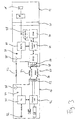
- the hearing system of Fig. 1 comprises a remote unit 10, an audio signal radio frequency receiver unit 12 and a hearing device 14.
- the hearing device 14 comprises an output transducer 16 for stimulation of a user's hearing, which typically will be an electro-acoustic transducer (speaker), with the hearing device 14 being designed such that the speaker 16 is located close to the outer and of the user's ear canal or within the ear canal when the hearing device 14 is worn by the user.
- the hearing device 14 comprises an audio signal processing unit 18 for processing the input audio signals to the output transducer 16.
- the hearing device 14 may be any type of headset or it may be a hearing aid / hearing instrument.
- the output transducer 16 could be a speaker, a cochlear implant (direct electrical stimulation of the inner ear) or an electro-mechanical transducer for direct mechanical stimulation of the middle ear or inner ear.
- the hearing aid may be arranged behind the ear, or partly or completely within the ear canal. In case that the hearing device 14 is not a hearing aid, it preferably may be a headset for a tourist tour guide or a museum guide system.
- the radio frequency receiver unit 12 may provide the input audio signals to the hearing device 14 via a standardized interface 20. Alternatively, the radio frequency receiver unit 12 may be integrated within the hearing device 14. In any case, the radio frequency receiver unit 12 is adapted to establish a radio frequency link 22 for wireless transmission of audio signals from the remote unit 10. Usually, the radio frequency link 22 will be a frequency modulated (FM) link.
- the remote unit 10 comprises an RF transmitter/ receiver 24 and the RF receiver unit 12 comprises a receiver/transmitter 26.
- the receiver/transmitters 24, 26 each comprise an antenna 28 and a transceiver 30.
- the remote unit 10 comprises an audio signal source 32 which is usually a microphone.
- the remote unit 10 preferably is a hand-held device, which picks up the voice of a person using the remote unit 10, such as a teacher in a classroom for persons with hearing loss or the guide of a tourist tour or a museum tour, via the microphone 32, with this audio signal being transmitted via the RF link 22 to the RF receiver unit 12 and from there to output transducer 16 in order to provide the user of the hearing device 14 with the voice of the person using the remote unit 10.
- the communication between the remote unit 10 and the RF receiver unit 12 would be unidirectional, namely from the remote unit 10 to the RF receiver unit 12, so that in a conventional system in the remote unit 10 only a RF transmitter function and in the RF receiver unit 12 only a RF receiver function would be necessary.
- such conventional system is modified such that the person using the remote unit 10 can easily monitor the RF audio link 22 by causing the RF receiver unit 12 to send status information regarding the status of the RF audio link 22 and/or the RF receiver unit 12 to the remote unit 10.
- This is achieved by providing the remote unit 10 with means for transmitting a polling signal/command 34 to the RF receiver unit 12 which is provided with means for receiving such polling signals 34.
- the RF receiver unit 12 is provided with means for generating and wirelessly transmitting, when the polling signal 34 has been received, a status information signal 36 containing data regarding the status of the RF link 22 and/or the RF receiver unit 12 to the remote unit 10 which is provided with means for receiving the status information signal 36 and displaying, via a display 38, status information derived from the status information signal 36.
- the remote unit 10 comprises a control unit 42 which controls the receiver/transmitter 24 and receives the status information signal from the transmitter/receiver 24 and an activation element 40 for causing the control unit 42 and the receiver/transmitter 24 to generate and wirelessly transmit the polling signal 34.
- the activation element 40 may be manually operable and/or it may be an activation timer in order to periodically generate and transmit the polling signal 34.
- the RF receiver unit 12 comprises a control unit 44 which controls the transmitter/receiver 26, a non-volatile memory 46 and an analysis unit 48 for analyzing the audio signal received by the transmitter/receiver 26. Both the analysis unit 48 and the memory 46 communicate with the control unit 44.
- the memory 46 contains the program for operating the RF receiver unit 12 and data needed for operation of the RF receiver unit 12.
- the remote unit 10 and the RF receiver unit 12 preferably are designed such that the audio signal from the remote unit 10 can be transmitted through a plurality of different frequency bands/channels.
- a specific frequency channel can be used in order to avoid reception of audio signals from an adjacent classroom.
- the selection of the respective frequency channel for each RF receiver unit 12 may be achieved, for example, by a synchronization unit mounted at the wall of each classroom.
- the status information signal 36 would include information regarding the channel on which the respective RF receiver unit 12 is set. Thereby the teacher immediately could recognize from the display 38 whether the respective pupil wearing the respective RF receiver unit 12, for example, is using a wrong frequency channel so that he could not receive the audio signal transmitted by the remote unit 10.
- the status information signal 36 may contain information regarding the signal to noise ratio of the RF audio link 22 as detected by the analysis unit 48. Further, the status information signal may include information regarding the integrity of the electrical connections between the RF receiver unit 12 and the hearing device 14 via the interface 20.
- the RF link carrying the polling signal 34 uses the same channel as the RF audio link 22 and also the status information signal 36 uses the same channel as the RF audio link 22.
- the transmitter function of the transmitter/receiver 24 of the remote unit 10 may be used not only for the RF audio link 22 but also for the link for the polling signal 34.
- Transmission and reception of the status information signal 36 may occur via the antennas 28 of the remote unit 10 and the RF receiver unit 12, respectively, which are already used for the RF audio link 22.
- Such multiple use of the RF audio link channel can be achieved by interrupting the RF audio link 22 while the status information signal 22 or the polling signal 34 is transmitted.
- the status information signal 36 and the polling signal 34 typically are transmitted at a low data rate of 100 bps to 2 kbps.
- Fig. 2 shows an example of an alternative embodiment wherein the polling signal 34 and the status information signal 36 are not transmitted via the same channel as the RF audio signal but rather a separate wireless channel 50 is provided for transmission of the polling signal 34 and the status information signal 36.
- this separate channel 50 is an inductive link comprising an inductive antenna 52 provided at the remote unit 10 and connected with the control unit 42 and an inductive antenna 54 provided at the RF receiver unit 12 and connected with the control unit 44.
- the antennas 52 and 54 are adapted both for transmitting and receiving, with the antenna 52 transmitting the polling signal 34 and receiving the status information signal 36 and with the antenna 54 transmitting the status information signal 36 and receiving the polling signal 34.
- the inductive link 50 may be, for example, a 40 kHz FSK modulated inductive channel such as it is conventionally used for remote control purposes and programming of RF receiver units for hearing aids.
- the inductive link 50 in addition to transmitting the polling signal 34 and the status information signal 36, may be used for transmitting remote control commands to the RF receiver unit 12, such as commands for setting the frequency or frequency band of the audio RF link 22 and/or commands for setting the operation mode and operation parameters of the RF receiver unit 12, such as audio volume setting and gain setting.
- the receiver/transmitter 24 of Fig. 1 is replaced by an audio signal transmitter 25 comprising an antenna 28 and a transmitter element 31 replacing the transceiver 30.
- Fig. 3 shows an embodiment wherein the separate link 50 for the polling signal 34 and the status information signal 36 is realized as a powerless system by using a powerless electromagnetic signal response device 56 at the RF receiver unit 12.
- RFID radio frequency identification
- Such powerless response devices are known as radio frequency identification (RFID) systems and are commonly used, for example, in door access systems or theft surveillance systems.
- RFID-Handbook 2 nd edition, by Klaus Finkenzeller, Wiley and Sons Ltd., April 2003.
- the response device 56 is adapted to be energized by energy included in the polling signal 34,with the status information signal 36 being encoded in a modulation of the polling signal 34 caused by the response device 56.
- the range of RFID systems may be increased by powering the signal response device 56.
- the response device 56 may include an antenna 58, an analogue circuit for receiving and transmitting RF signals, a digital circuit and a data memory wherein the status information basic to a status information signal 36 is stored by action of the control unit 44.
- these RF receiver units 12 have to be addressed individually for gaining the desired status information signal 36 from a selected RF receiver unit 12. This can be achieved, for example, by transmitting dedicated device addresses from the remote unit 10 in order to specifically address a selected one of the RF receiver units 12. Such dedicated device addresses may be included in the polling signal 34. Such addresses may advantageously be programmable in both units 10 and 12.
- Another option is to achieve selection of the RF receiver unit 12 by controlling the range of the polling signal 34. This option is particularly appropriate if the polling signal 34 is transmitted via an inductive link, since the decay of inductive signals with the distance from the transmitter is extrernely steep. In this case, selection of the RF receiver unit 12 is practically achieved by approaching the selected RF receiver unit 12 with the remote unit 10 (for example, the teacher using a remote unit 10 approaches the pupil using the selected RF receiver unit 12).
- the status information signal 36 may include information on whether the RF receiver unit 12 is for a right ear or for a left ear. Such information can be provided, for example, by delaying the status information signal 36 depending on whether the RF receiver unit 12 is for a right ear or for a left ear.
Landscapes
- Engineering & Computer Science (AREA)
- Health & Medical Sciences (AREA)
- General Health & Medical Sciences (AREA)
- Otolaryngology (AREA)
- Neurosurgery (AREA)
- Physics & Mathematics (AREA)
- Acoustics & Sound (AREA)
- Signal Processing (AREA)
- Computer Networks & Wireless Communication (AREA)
- Selective Calling Equipment (AREA)
- Monitoring And Testing Of Transmission In General (AREA)
Abstract
Description
- The present invention relates to a hearing system comprising a hearing device to which an external audio signal is provided via a wireless, typically a radio frequency (RF) link. The invention also relates to a system for providing audio signals to a hearing device via a wireless link and to a method for monitoring a hearing system comprising a hearing device to which audio signals are provided via a wireless link.
- It is well known to provide an external audio signal to a hearing aid via a radio frequency (RF) link, usually a frequency modulated (FM) link. The RF receiver can be integrated within the hearing aid or it can be an external component which is connected to the hearing aid via a suited and often standardized mechanical and electrical interface. A common application of such systems is the education of students in a classroom by a teacher. In this case the external audio signal is the teacher's voice which is picked-up by a microphone and is sent to the hearing aid of each student via the RF link. Another application of such a wireless system is the case in which parents want to communicate with their child wearing a hearing aid via a wireless microphone and a RF link to the hearing aid.
- Conventionally, single channel FM receivers were used for establishing the RF link between the remote audio signal source and the hearing aid. Such systems are available with a "no FM" indicator LED indicating the absence of a carrier on the receiving channel. Such conventional devices are strictly unidirectional, with no signal being sent back from the RF receiver.
- More recent devices are designed as multi-channel receivers capable of changing between several audio signal transmission channels, i.e. frequency bands. With such devices, for example, each teacher may use his own transmission channel. Further, the students may be addressed individually via associated transmission channels. The selection of the receiving channel of the RF receiver may be controlled automatically, for example, by a wireless control panel installed at the wall of each classroom.
- Further, it is known to use an RF link for remote programming of a hearing aid, respectively an FM receiver. An example of a multichannel RF system for a hearing aid is described in WO 02/23948 Al, wherein the RF receiver connected to the hearing aid also is adapted for remote programming via an FSK (frequency shift keying) modulation used for data transmission between the remote programming unit and the RF receiver. Such FSK link is bidirectional, wherein the RF receiver may transmit information regarding the version of the software installed in the hearing aid to the remote programming unit. It is also mentioned in WO 02/23948 A1 that the bidirectional link for remote programming also could be an inductive link rather than a RF link.
- In products which are presently on the market the bidirectional remote programming wireless link may be used for reading identifying information such as serial number, school and student's name from the RF receiver.
- An example for a wireless remote control for a hearing aid is given in EP 0681411 B1, wherein the hearing aid has a transmitter/receiver unit for establishing wireless communication with the transmitter/receiver unit of a remote control, wherein audiometric data, hearing parameters, algorithms, fuzzy input and configuration information can be transmitted from the hearing aid to the remote control.
- US 5,721,783 describes a "distributed" hearing system, comprising an earpiece including a speaker and a microphone and a body-worn remote processor unit between which a bidirectional RF link is established for transmitting audio signals generated in the earpiece by the microphone to the remote processor unit for signal processing, with the processed audio signals being sent back from the remote processing unit to the earpiece for providing an acoustic signal via the speaker in the earpiece to the user. Thus, the RF link is used for bidirectional transmission of audio signals. A secondary wireless link may be provided to the remote processor unit for supplying external audio signals, such as from a telephone, to the speaker of the earpiece.
- There are many applications of a hearing device provided with external audio signals via a wireless link in which it would be desirable to know whether the user of the hearing device properly receives the transmitted external audio signal. This applies particularly to the case in which the user of the hearing device is a child. The reason is that usually adults will easily remark and complain about non-working radio systems, while this cannot be expected in all cases from children, even more so in classroom applications.
- Consequently it is an object of the invention to provide for a hearing system comprising a hearing device provided with an external audio signal via a wireless link, which allows a person, such as teachers or parents to monitor the reception of the external audio signal by the user of the hearing device. It is a further object of the invention to provide for a corresponding system for providing audio signals to a hearing device via a wireless link. It is a still further object of the invention to provide for a method for monitoring a hearing system comprising a hearing device provided with external audio signals via a wireless link.
- These objects are achieved by a hearing system as defined in
claim 1, a system for providing audio signals to a hearing device as defined in claim 29 and a method for monitoring a hearing system as defined inclaim 30, respectively. - The invention is beneficial in that, by polling the audio signal receiver unit in order to transmit a status information signal containing data regarding the status of the wireless audio link and/or the audio signal receiver unit and by displaying such status information, the wireless audio signal link can be monitored in a very easy manner by persons other than the user of the hearing device. This is particularly beneficial if the user of the hearing device is a child and the parents or a teacher of the child wishes to know whether at all and/or in which quality the external audio signal, for example, the parent's or teacher's voice, can be received by the child.
- In general, the hearing device could be any type of wireless headset, such as a part of a tourist tour guide or museum guide system. However, preferably the hearing device is a hearing aid. Preferably, the status information signal in this case includes information regarding at least one of the following: integrity of the electrical connections between the audio signal receiver and the hearing aid, present frequency (channel) or frequency band of the wireless link carrying the audio signal, confirmation of remote control commands for setting the operation mode/operation parameters of the audio signal receiver unit, present operation mode of the audio signal receiver unit, present setting of operation parameters of the audio signal receiver unit, signal to noise ratio of the wireless link carrying the audio signal, battery status of the audio signal receiver unit or of the hearing aid, identification of the audio signal receiver unit among a plurality of audio signal receiver units, date of last servicing of the audio signal receiver unit, and user's name. The status information signal also may include information regarding the present operation mode of the hearing aid and/or present setting of operation parameters of the hearing aid, which information is provided via an interface from the hearing aid to the audio signal receiver unit.
- Usually the wireless link carrying the audio signal will be a radio frequency link, preferably an
- FM (frequency modulation) link.
- Preferably, the audio signal source is a remote microphone, which is used, for example, by a teacher in the classroom.
- The status information signal may include data on whether the audio signal receiver unit is for a right ear or a left ear. In this case, the left ear / right ear differentiation of the status information may be done by time-delaying the response of the right and the left audio signal receiver unit.
- According to a preferred embodiment, the audio signal source and/or the audio signal transmitter and/or the means for generating and transmitting the polling signal and/or the means for receiving the status information signal and displaying status information are integrated in a common device which is a portable, preferably hand-held, device.
- Preferably, the means for receiving the status information signal and displaying status information is adapted to display the status information graphically. The means for receiving the status information signal and displaying status information may be adapted to display the status information together with data identifying the audio signal receiver unit among a plurality of audio signal receiver units, whereby the displayed status information can be easily attributed to a certain person.
- The means for generating and transmitting the polling signal may comprise an activation element which is manually operable and/or an activation timer in order to periodically generate and transmit the polling signal.
- According to one embodiment, the means for generating and transmitting the polling signal may be adapted to establish a radio frequency link to the means for receiving the polling signal, wherein the radio frequency link carrying the polling signal preferably uses the same channel as the radio frequency link carrying the audio signal, with the polling signal being transmitted by the audio signal transmitter.
- In an alternative embodiment, the means for generating and transmitting the polling signal may be adapted to establish an inductive link to the means for receiving the polling signal.
- According to a further alternative embodiment, the means for receiving the polling signal and the means for generating and wirelessly transmitting the status information signal comprise a powerless electromagnetic signal response means adapted to be energized by energy included in the polling signal, with the status information signal being encoded in a modulation of the polling signal by the powerless electromagnetic signal response means. As a variant, the means for generating and wirelessly transmitting the status information signal may be a powerless electromagnetic signal response means adapted to be energized by energy included in an electromagnetic signal emitted by the means for receiving the status information signal, with the status information signal being encoded in a modulation of that electromagnetic signal by the powerless electromagnetic signal response means. Preferably, the powerless electromagnetic signal response means is an RFID (radio frequency identification) device.
- The means for generating and transmitting the polling signal may comprise means for transmitting dedicated device addresses in order to specifically address the radio frequency receiver unit among a plurality of radio frequency receiver units.
- Preferably, the means for generating and transmitting the polling signal comprise an FSK (frequency shift keying) modulator.
- According to one embodiment, the means for generating and transmitting the status information signal and the means for receiving the status information signal and displaying status information are adapted to establish a radio frequency link carrying the status information signal, wherein the means for generating and transmitting the status information signal may comprise an FSK modulator. Preferably, the means for generating and transmitting the status information signal is adapted to use the same channel as radio frequency link carrying the audio signal, with the status information signal being transmitted via the antenna of the radio frequency receiver unit. The radio frequency transmitter and the radio frequency receiver unit in this case are preferably adapted to interrupt the radio frequency link carrying the audio signal while the status information signal is transmitted. This can be achieved by providing the radio frequency receiver unit with a RX/TX switch for the antenna.
- Typically, the status information signal and/or the polling signal will be transmitted at a data rate of 100 bps to 2 kbps.
- The means for generating and transmitting the polling signal and the means for receiving the polling signal at the audio signal receiver unit may be adapted to transmit remote control commands to the audio signal receiver unit, wherein the remote control commands may include commands for setting the frequency (channel) or frequency band of the wireless link carrying the audio signal and/or commands for setting the operation mode and operation parameters of the audio signal receiver unit, such as audio volume setting and gain setting.
- In the following, preferred embodiments of the invention will be illustrated by reference to the attached drawings.
- Fig. 1
- shows a schematic block diagram of a wireless hearing system according to a first embodiment of the invention;
- Fig. 2
- shows a view like Fig. 1 of a second embodiment of the invention; and
- Fig. 3
- shows a view like Fig. 1 of a third embodiment of the invention.
- The hearing system of Fig. 1 comprises a
remote unit 10, an audio signal radiofrequency receiver unit 12 and ahearing device 14. Thehearing device 14 comprises anoutput transducer 16 for stimulation of a user's hearing, which typically will be an electro-acoustic transducer (speaker), with thehearing device 14 being designed such that thespeaker 16 is located close to the outer and of the user's ear canal or within the ear canal when thehearing device 14 is worn by the user. Further, thehearing device 14 comprises an audiosignal processing unit 18 for processing the input audio signals to theoutput transducer 16. - The
hearing device 14 may be any type of headset or it may be a hearing aid / hearing instrument. In the latter case, theoutput transducer 16 could be a speaker, a cochlear implant (direct electrical stimulation of the inner ear) or an electro-mechanical transducer for direct mechanical stimulation of the middle ear or inner ear. The hearing aid may be arranged behind the ear, or partly or completely within the ear canal. In case that thehearing device 14 is not a hearing aid, it preferably may be a headset for a tourist tour guide or a museum guide system. - The radio
frequency receiver unit 12 may provide the input audio signals to thehearing device 14 via astandardized interface 20. Alternatively, the radiofrequency receiver unit 12 may be integrated within thehearing device 14. In any case, the radiofrequency receiver unit 12 is adapted to establish aradio frequency link 22 for wireless transmission of audio signals from theremote unit 10. Usually, theradio frequency link 22 will be a frequency modulated (FM) link. To this end, theremote unit 10 comprises an RF transmitter/receiver 24 and theRF receiver unit 12 comprises a receiver/transmitter 26. The receiver/transmitters antenna 28 and atransceiver 30. - The
remote unit 10 comprises anaudio signal source 32 which is usually a microphone. Theremote unit 10 preferably is a hand-held device, which picks up the voice of a person using theremote unit 10, such as a teacher in a classroom for persons with hearing loss or the guide of a tourist tour or a museum tour, via themicrophone 32, with this audio signal being transmitted via theRF link 22 to theRF receiver unit 12 and from there tooutput transducer 16 in order to provide the user of thehearing device 14 with the voice of the person using theremote unit 10. In a conventional system, the communication between theremote unit 10 and theRF receiver unit 12 would be unidirectional, namely from theremote unit 10 to theRF receiver unit 12, so that in a conventional system in theremote unit 10 only a RF transmitter function and in theRF receiver unit 12 only a RF receiver function would be necessary. - According to the present invention, such conventional system is modified such that the person using the
remote unit 10 can easily monitor theRF audio link 22 by causing theRF receiver unit 12 to send status information regarding the status of theRF audio link 22 and/or theRF receiver unit 12 to theremote unit 10. This is achieved by providing theremote unit 10 with means for transmitting a polling signal/command 34 to theRF receiver unit 12 which is provided with means for receiving such polling signals 34. in addition, theRF receiver unit 12 is provided with means for generating and wirelessly transmitting, when thepolling signal 34 has been received, astatus information signal 36 containing data regarding the status of theRF link 22 and/or theRF receiver unit 12 to theremote unit 10 which is provided with means for receiving thestatus information signal 36 and displaying, via adisplay 38, status information derived from thestatus information signal 36. Theremote unit 10 comprises acontrol unit 42 which controls the receiver/transmitter 24 and receives the status information signal from the transmitter/receiver 24 and anactivation element 40 for causing thecontrol unit 42 and the receiver/transmitter 24 to generate and wirelessly transmit thepolling signal 34. Theactivation element 40 may be manually operable and/or it may be an activation timer in order to periodically generate and transmit thepolling signal 34. TheRF receiver unit 12 comprises acontrol unit 44 which controls the transmitter/receiver 26, anon-volatile memory 46 and an analysis unit 48 for analyzing the audio signal received by the transmitter/receiver 26. Both the analysis unit 48 and thememory 46 communicate with thecontrol unit 44. Thememory 46 contains the program for operating theRF receiver unit 12 and data needed for operation of theRF receiver unit 12. - The
remote unit 10 and theRF receiver unit 12 preferably are designed such that the audio signal from theremote unit 10 can be transmitted through a plurality of different frequency bands/channels. With such a system, for example, in each classroom a specific frequency channel can be used in order to avoid reception of audio signals from an adjacent classroom. The selection of the respective frequency channel for eachRF receiver unit 12 may be achieved, for example, by a synchronization unit mounted at the wall of each classroom. For such a multichannel system thestatus information signal 36 would include information regarding the channel on which the respectiveRF receiver unit 12 is set. Thereby the teacher immediately could recognize from thedisplay 38 whether the respective pupil wearing the respectiveRF receiver unit 12, for example, is using a wrong frequency channel so that he could not receive the audio signal transmitted by theremote unit 10. In addition, thestatus information signal 36 may contain information regarding the signal to noise ratio of theRF audio link 22 as detected by the analysis unit 48. Further, the status information signal may include information regarding the integrity of the electrical connections between theRF receiver unit 12 and thehearing device 14 via theinterface 20. - In the embodiment of Fig. 1 the RF link carrying the
polling signal 34 uses the same channel as theRF audio link 22 and also thestatus information signal 36 uses the same channel as theRF audio link 22. Thereby the transmitter function of the transmitter/receiver 24 of theremote unit 10 may be used not only for theRF audio link 22 but also for the link for thepolling signal 34. This applies analogously also to the receiver function of the receiver/transmitter 26 of theRF receiver unit 12. Transmission and reception of thestatus information signal 36 may occur via theantennas 28 of theremote unit 10 and theRF receiver unit 12, respectively, which are already used for theRF audio link 22. Such multiple use of the RF audio link channel can be achieved by interrupting theRF audio link 22 while thestatus information signal 22 or thepolling signal 34 is transmitted. - The
status information signal 36 and thepolling signal 34 typically are transmitted at a low data rate of 100 bps to 2 kbps. - Fig. 2 shows an example of an alternative embodiment wherein the
polling signal 34 and thestatus information signal 36 are not transmitted via the same channel as the RF audio signal but rather aseparate wireless channel 50 is provided for transmission of thepolling signal 34 and thestatus information signal 36. In the case of the embodiment shown in Fig. 2, thisseparate channel 50 is an inductive link comprising aninductive antenna 52 provided at theremote unit 10 and connected with thecontrol unit 42 and aninductive antenna 54 provided at theRF receiver unit 12 and connected with thecontrol unit 44. Theantennas antenna 52 transmitting thepolling signal 34 and receiving thestatus information signal 36 and with theantenna 54 transmitting thestatus information signal 36 and receiving thepolling signal 34. - The
inductive link 50 may be, for example, a 40 kHz FSK modulated inductive channel such as it is conventionally used for remote control purposes and programming of RF receiver units for hearing aids. Preferably, theinductive link 50, in addition to transmitting thepolling signal 34 and thestatus information signal 36, may be used for transmitting remote control commands to theRF receiver unit 12, such as commands for setting the frequency or frequency band of theaudio RF link 22 and/or commands for setting the operation mode and operation parameters of theRF receiver unit 12, such as audio volume setting and gain setting. In the embodiments of Figs. 2 and 3 the receiver/transmitter 24 of Fig. 1 is replaced by an audio signal transmitter 25 comprising anantenna 28 and a transmitter element 31 replacing thetransceiver 30. - Fig. 3 shows an embodiment wherein the
separate link 50 for thepolling signal 34 and thestatus information signal 36 is realized as a powerless system by using a powerless electromagneticsignal response device 56 at theRF receiver unit 12, Such powerless response devices are known as radio frequency identification (RFID) systems and are commonly used, for example, in door access systems or theft surveillance systems. A description of RFID systems may be found, for example, in the "RFID-Handbook", 2nd edition, by Klaus Finkenzeller, Wiley and Sons Ltd., April 2003. In the embodiment of Fig. 3 theresponse device 56 is adapted to be energized by energy included in thepolling signal 34,with thestatus information signal 36 being encoded in a modulation of thepolling signal 34 caused by theresponse device 56. The range of RFID systems may be increased by powering thesignal response device 56. - The
response device 56 may include anantenna 58, an analogue circuit for receiving and transmitting RF signals, a digital circuit and a data memory wherein the status information basic to astatus information signal 36 is stored by action of thecontrol unit 44. - Generally, in all embodiments in which the
remote unit 10 is used for providing audio signals to a plurality ofRF receiver units 12 simultaneously, theseRF receiver units 12 have to be addressed individually for gaining the desired status information signal 36 from a selectedRF receiver unit 12. This can be achieved, for example, by transmitting dedicated device addresses from theremote unit 10 in order to specifically address a selected one of theRF receiver units 12. Such dedicated device addresses may be included in thepolling signal 34. Such addresses may advantageously be programmable in bothunits RF receiver unit 12 by controlling the range of thepolling signal 34. This option is particularly appropriate if thepolling signal 34 is transmitted via an inductive link, since the decay of inductive signals with the distance from the transmitter is extrernely steep. In this case, selection of theRF receiver unit 12 is practically achieved by approaching the selectedRF receiver unit 12 with the remote unit 10 (for example, the teacher using aremote unit 10 approaches the pupil using the selected RF receiver unit 12). - In order to enable a distinction between the
FM receiver unit 12 used for the right ear and that used for the left ear thestatus information signal 36 may include information on whether theRF receiver unit 12 is for a right ear or for a left ear. Such information can be provided, for example, by delaying thestatus information signal 36 depending on whether theRF receiver unit 12 is for a right ear or for a left ear.
Claims (30)
- Hearing system comprising a hearing device (14) having an output transducer (16) for stimulation of a user's hearing, an audio signal transmitter (24, 25), an audio signal source (32) for providing audio signals to the audio signal transmitter, an audio signal receiver unit (12) adapted to establish a wireless link (22) for transmission of the audio signals from the audio signal transmitter to the audio signal receiver unit which is connected to or integrated within the hearing device for providing the audio signals received from the audio signal transmitter as input to the hearing device, means (24, 28, 30, 40, 42, 52) for generating and wirelessly transmitting a polling signal (34) to the audio signal receiver unit, means (26, 28, 30, 44, 54, 56, 58) for receiving the polling signal at the audio signal receiver unit, means (26, 28, 30, 44, 48, 54, 56, 58) for generating and wirelessly transmitting, when the polling signal has been received, a status information signal (36) containing data regarding the status of the wireless audio signal link and/or the receiver unit, and means (24, 28, 30, 38, 42, 52) for receiving the status information signal and displaying status information derived from the status information signal.
- The system of claim. 1, wherein the audio signal source (32) and/or the transmitter (24, 25) and/or the means (24, 28, 30, 40, 42, 52) for generating and transmitting the polling signal (34) and/or the means (24,28, 30, 38, 42, 52) for receiving the status information signal and displaying status information are integrated in a common device (10).
- The system of claim 2, wherein the common device (10) is a portable, preferably handheld, device.
- The system of one of the preceding claims, wherein the means (24, 28, 30, 38, 42, 52) for receiving the status information signal (36) and displaying status information is adapted to display the status information graphically.
- The system of one of the preceding claims, wherein the means (24, 28, 30, 38, 42, 52) for receiving the status information signal (36) and displaying status information is adapted to display the status information together with data identifying the audio signal receiver unit (12) among a plurality of audio signal receiver units.
- The system of one of the preceding claims, wherein the means (24, 28, 30, 40, 42, 52) for generating and transmitting the polling signal (34) comprise an activation element (40) which is manually operable and/or an activation timer in order to periodically generate and transmit the polling signal.
- The system of one of the preceding claims, wherein the means (24, 28, 30, 40, 42) for generating and transmitting the polling signal (34) is adapted to establish a radio frequency link to the means (26,28, 30, 44) for receiving the polling signal.
- The system of one of the preceding claims, wherein the audio signal transmitter (24, 25) and the audio signal receiver unit (12) are adapted to establish a radio frequency link for the audio signal.
- The system of claims 7 and 8, wherein the radio frequency link carrying the polling signal (34) uses the same channel as the radio frequency link (22) carrying the audio signal, with the polling signal being transmitted by the radio frequency transmitter (24).
- The system of one of claims 1 to 6, wherein the means (42, 52) for generating and transmitting the polling signal (34) is adapted to establish an inductive link to the means (44, 54) for receiving the polling signal.
- The system of one of the preceding claims, wherein the means (24, 28, 30, 40, 42, 52) for generating and transmitting the polling signal (34) comprises means for transmitting dedicated device addresses in order to specifically address the audio signal receiver unit (12) among a plurality of audio signal receiver units.
- The system of one of the preceding claims, wherein the means (24, 28, 30, 40, 42, 52) for generating and transmitting the polling signal (34) comprises a frequency shift keying (FSK) modulator.
- The system of one of the preceding claims, wherein the means (26, 28, 30, 44, 48) for generating and transmitting the status information signal (36) and the means (24, 28, 30, 38, 42) for receiving the status information signal and displaying status information are adapted to establish a radio frequency link carrying the status information signal.
- The system of claim 13, wherein the means (26, 28, 30, 44, 48, 54, 56, 58) for generating and transmitting the status information signal (36) comprises a frequency shift keying (FSK) modulator.
- The system of claim 8 and one of claims 13 and 14, wherein the means (26, 28, 30, 44, 48, 54, 56, 58) for generating and transmitting the status information signal (36) is adapted to use the same channel as the radio frequency link (22) carrying the audio signal, with the status information signal being transmitted via the antenna (28) of the audio signal receiver unit (12).
- The system of claim 15, wherein the audio signal transmitter (24) and the audio signal receiver unit (12) are adapted to interrupt the radio frequency link (22) carrying the audio signal while the status information signal (36) is transmitted.
- The system of one of claims I to 12, wherein the means (44, 48, 54, 56, 58) for generating and transmitting the status information signal (36) and the means (38, 42, 52) for receiving the status information signal and displaying status information are adapted to establish an inductive link carrying the status information signal.
- The system of one of claims 1 to 12, wherein the means (56, 58) for receiving the polling signal (34) and the means (44, 48, 56, 58) for generating and wirelessly transmitting the status information signal (36) comprise a powerless electromagnetic signal response means (56, 58) adapted to be energized by energy included in the polling signal, with the status information signal being encoded in a modulation of the polling signal caused by the powerless electromagnetic signal response means.
- The system of one of the preceding claims, wherein the status information signal (36) and/or the polling signal (34) is transmitted at a data rate of 100 bps to 2 kbps.
- The system of one of the preceding claims, wherein the means (24, 28, 30, 40, 42, 52) for generating and transmitting the polling signal (34) and the means (26, 28, 30, 44, 54, 56, 58) for receiving the polling signal at the audio signal receiver unit (12) are adapted to transmit remote control commands to the audio signal receiver unit.
- The system of claim 20, wherein the remote control commands include commands for setting the frequency or frequency band of the wireless link (22) carrying the audio signal and/or commands for setting the operation mode and operation parameters of the audio signal receiver unit (12), such as audio volume setting and gain setting.
- The system of one of the preceding claims, wherein the hearing device (14) is a hearing aid.
- The system of claim 22, wherein the status information signal (12) includes information regarding at least one of the following: the integrity of the electrical connections between the audio signal receiver unit (12) and the hearing aid (14), the present frequency or frequency band of the wireless link (22) carrying the audio signal, confirmation of remote control commands for setting the operation mode/operation parameters of the audio signal receiver unit, present operation mode of the audio signal receiver unit, present setting of operation parameters of the audio signal receiver unit, signal to noise ratio of the wireless link carrying the audio signal, battery status of the audio signal receiver unit or the hearing aid, identification of the audio signal receiver unit among a plurality of audio signal receiver units, date of last servicing of the audio signal receiver unit, and user's name.
- The system of claim 22, wherein the status information signal (12) includes information regarding the present operation mode of the hearing aid (14) and/or present setting of operation parameters of the hearing aid.
- The system of one of the preceding claims, wherein the status information signal (36) includes data on whether the audio signal receiver unit (12) is for a right ear or a left ear.
- The system of claim 25, wherein transmission of the status information signal (36) is time-delayed depending on whether the audio signal receiver unit (12) is for a right ear or a left ear.
- The system of one of the preceding claims, wherein the wireless link (22) carrying the audio signal is aa frequency modulation (FM) link.
- The system of one of the preceding claims, wherein the audio signal source is a remote microphone (32).
- System for providing audio signals to a hearing device (14) having an output transducer (16) for stimulation of a user's hearing, comprising: an audio signal transmitter (24, 25), an audio signal source (32) for providing audio signals to the audio signal transmitter, an audio signal receiver unit (12) adapted to establish a wireless link (22) for transmission of the audio signals from the audio signal transmitter to the audio signal receiver unit which is adapted to be connected to the hearing device for providing the audio signals received from the audio signal transmitter as input to the hearing device, means (24, 28, 30, 40, 42, 52) for generating and wirelessly transmitting a polling signal (34) to the audio signal receiver unit, means (26, 28, 30, 44, 54, 56, 58) for receiving the polling signal at the audio signal receiver unit, means (26, 28, 30, 44, 48, 54, 56, 58) for generating and wirelessly transmitting, when the polling signal has been received, a status information signal (36) containing data regarding the status of the wireless audio signal link and/or the audio signal receiver unit, and means (24, 28, 30, 38, 42, 52) for receiving the status information signal and displaying status information derived from the status information signal.
- Method for monitoring a hearing system comprising a hearing device (14) having an output transducer (16) for stimulation of a user's hearing, an audio signal transmitter (24, 25), an audio signal source (32), and an audio signal receiver unit (12) connected to or integrated within the hearing device, comprising:providing audio signals from the audio source to the audio signal transmitter;establishing a wireless link (22) for transmission of the audio signals from the audio signal transmitter to the audio signal receiver unit;providing the audio signals received by the audio signal receiver unit from the audio signal transmitter as input to the hearing device;generating and wirelessly transmitting a polling signal (34) to the audio signal receiver unit;receiving the polling signal at the audio signal receiver unit;generating and wirelessly transmitting, upon reception of the polling signal, a status information signal (36) containing data regarding the status of the wireless audio signal link and/or the audio signal receiver unit;receiving the status information signal; anddisplaying status information derived from the status information signal.
Priority Applications (2)
| Application Number | Priority Date | Filing Date | Title |
|---|---|---|---|
| EP05028365.4A EP1638367B1 (en) | 2005-12-23 | 2005-12-23 | Wireless hearing system and method for monitoring the same |
| DK05028365.4T DK1638367T3 (en) | 2005-12-23 | 2005-12-23 | Wireless hearing system and method for monitoring the same |
Applications Claiming Priority (1)
| Application Number | Priority Date | Filing Date | Title |
|---|---|---|---|
| EP05028365.4A EP1638367B1 (en) | 2005-12-23 | 2005-12-23 | Wireless hearing system and method for monitoring the same |
Publications (3)
| Publication Number | Publication Date |
|---|---|
| EP1638367A2 true EP1638367A2 (en) | 2006-03-22 |
| EP1638367A3 EP1638367A3 (en) | 2006-07-19 |
| EP1638367B1 EP1638367B1 (en) | 2015-10-21 |
Family
ID=35636907
Family Applications (1)
| Application Number | Title | Priority Date | Filing Date |
|---|---|---|---|
| EP05028365.4A Active EP1638367B1 (en) | 2005-12-23 | 2005-12-23 | Wireless hearing system and method for monitoring the same |
Country Status (2)
| Country | Link |
|---|---|
| EP (1) | EP1638367B1 (en) |
| DK (1) | DK1638367T3 (en) |
Cited By (18)
| Publication number | Priority date | Publication date | Assignee | Title |
|---|---|---|---|---|
| WO2007144010A1 (en) * | 2006-06-12 | 2007-12-21 | Phonak Ag | Method for monitoring a hearing device and hearing device with self-monitoring function |
| DE102006030602A1 (en) * | 2006-07-03 | 2008-01-24 | Siemens Audiologische Technik Gmbh | Method for identifying hearing aids in the context of wireless programming |
| DE102006035007A1 (en) * | 2006-07-28 | 2008-01-31 | Siemens Audiologische Technik Gmbh | A hearing aid with a radio frequency identification receiver for switching a transmission characteristic |
| EP1933592A1 (en) * | 2006-12-11 | 2008-06-18 | Siemens Audiologische Technik GmbH | Self-programming hearing device and corresponding method |
| DE102007001536A1 (en) * | 2007-01-10 | 2008-07-17 | Siemens Audiologische Technik Gmbh | Detecting device for detecting hearing device, comprises communication device for communication with transponder, where evaluation device is provided for evaluating answer signal of transponder |
| EP1949756A1 (en) * | 2005-10-18 | 2008-07-30 | Craj Development Limited | Communication system |
| EP2012556A1 (en) * | 2007-07-06 | 2009-01-07 | Siemens Audiologische Technik GmbH | Method and system for exchanging data with a hearing aid |
| WO2009118424A2 (en) * | 2009-07-20 | 2009-10-01 | Phonak Ag | Hearing assistance system |
| US7738666B2 (en) | 2006-06-01 | 2010-06-15 | Phonak Ag | Method for adjusting a system for providing hearing assistance to a user |
| US7940945B2 (en) | 2006-07-06 | 2011-05-10 | Phonak Ag | Method for operating a wireless audio signal receiver unit and system for providing hearing assistance to a user |
| US7949144B2 (en) | 2006-06-12 | 2011-05-24 | Phonak Ag | Method for monitoring a hearing device and hearing device with self-monitoring function |
| US8077892B2 (en) | 2006-10-30 | 2011-12-13 | Phonak Ag | Hearing assistance system including data logging capability and method of operating the same |
| EP2408222A1 (en) | 2006-12-20 | 2012-01-18 | Phonak AG | Wireless communication system |
| EP2395804A3 (en) * | 2010-06-09 | 2013-02-20 | Hitachi Ltd. | Information distribution system, fixed station, mobile station, and information distribution method |
| US20150088501A1 (en) * | 2013-09-24 | 2015-03-26 | Starkey Laboratories, Inc. | Methods and apparatus for signal sharing to improve speech understanding |
| US9877116B2 (en) | 2013-12-30 | 2018-01-23 | Gn Hearing A/S | Hearing device with position data, audio system and related methods |
| US10154355B2 (en) | 2013-12-30 | 2018-12-11 | Gn Hearing A/S | Hearing device with position data and method of operating a hearing device |
| CN111050265A (en) * | 2019-11-27 | 2020-04-21 | 深圳易科声光科技股份有限公司 | Automatic audio link detection method and device |
Citations (3)
| Publication number | Priority date | Publication date | Assignee | Title |
|---|---|---|---|---|
| US5721783A (en) | 1995-06-07 | 1998-02-24 | Anderson; James C. | Hearing aid with wireless remote processor |
| WO2002023948A1 (en) | 2000-09-18 | 2002-03-21 | Phonak Ag | Method for controlling a transmission system, use of this method, transmission system, receiving unit and hearing aid |
| EP0681411B1 (en) | 1994-05-06 | 2003-01-29 | Siemens Audiologische Technik GmbH | Programmable hearing aid |
Family Cites Families (1)
| Publication number | Priority date | Publication date | Assignee | Title |
|---|---|---|---|---|
| US20030045283A1 (en) * | 2001-09-06 | 2003-03-06 | Hagedoorn Johan Jan | Bluetooth enabled hearing aid |
-
2005
- 2005-12-23 EP EP05028365.4A patent/EP1638367B1/en active Active
- 2005-12-23 DK DK05028365.4T patent/DK1638367T3/en active
Patent Citations (3)
| Publication number | Priority date | Publication date | Assignee | Title |
|---|---|---|---|---|
| EP0681411B1 (en) | 1994-05-06 | 2003-01-29 | Siemens Audiologische Technik GmbH | Programmable hearing aid |
| US5721783A (en) | 1995-06-07 | 1998-02-24 | Anderson; James C. | Hearing aid with wireless remote processor |
| WO2002023948A1 (en) | 2000-09-18 | 2002-03-21 | Phonak Ag | Method for controlling a transmission system, use of this method, transmission system, receiving unit and hearing aid |
Non-Patent Citations (1)
| Title |
|---|
| "RFID-HANDBOOK", April 2003, WILEY AND SONS LTD. |
Cited By (28)
| Publication number | Priority date | Publication date | Assignee | Title |
|---|---|---|---|---|
| US8340331B2 (en) | 2005-10-18 | 2012-12-25 | Carj Develpment Limited | Communication system |
| EP1949756A1 (en) * | 2005-10-18 | 2008-07-30 | Craj Development Limited | Communication system |
| EP1949756A4 (en) * | 2005-10-18 | 2010-03-24 | Craj Dev Ltd | Communication system |
| US7738666B2 (en) | 2006-06-01 | 2010-06-15 | Phonak Ag | Method for adjusting a system for providing hearing assistance to a user |
| US8467555B2 (en) | 2006-06-12 | 2013-06-18 | Phonak Ag | Method for monitoring a hearing device and hearing device with self-monitoring function |
| WO2007144010A1 (en) * | 2006-06-12 | 2007-12-21 | Phonak Ag | Method for monitoring a hearing device and hearing device with self-monitoring function |
| US7949144B2 (en) | 2006-06-12 | 2011-05-24 | Phonak Ag | Method for monitoring a hearing device and hearing device with self-monitoring function |
| DE102006030602A1 (en) * | 2006-07-03 | 2008-01-24 | Siemens Audiologische Technik Gmbh | Method for identifying hearing aids in the context of wireless programming |
| US8121322B2 (en) | 2006-07-03 | 2012-02-21 | Siemens Audiologische Technik Gmbh | Method for identifying hearing aids within the scope of wireless programming |
| US7940945B2 (en) | 2006-07-06 | 2011-05-10 | Phonak Ag | Method for operating a wireless audio signal receiver unit and system for providing hearing assistance to a user |
| DE102006035007A1 (en) * | 2006-07-28 | 2008-01-31 | Siemens Audiologische Technik Gmbh | A hearing aid with a radio frequency identification receiver for switching a transmission characteristic |
| US8199946B2 (en) | 2006-07-28 | 2012-06-12 | Siemens Audiologische Technik Gmbh | Hearing aid with radio frequency identification receiver for switching a transmission characteristic |
| US8077892B2 (en) | 2006-10-30 | 2011-12-13 | Phonak Ag | Hearing assistance system including data logging capability and method of operating the same |
| AU2007240220B2 (en) * | 2006-12-11 | 2010-12-23 | Sivantos Gmbh | Self-programming hearing apparatus and corresponding method |
| US8630432B2 (en) | 2006-12-11 | 2014-01-14 | Siemens Audiologische Technik Gmbh | Self-programming hearing apparatus and corresponding method |
| EP1933592A1 (en) * | 2006-12-11 | 2008-06-18 | Siemens Audiologische Technik GmbH | Self-programming hearing device and corresponding method |
| EP2408222A1 (en) | 2006-12-20 | 2012-01-18 | Phonak AG | Wireless communication system |
| US8144903B2 (en) | 2006-12-20 | 2012-03-27 | Phonak Ag | Wireless communication system |
| DE102007001536A1 (en) * | 2007-01-10 | 2008-07-17 | Siemens Audiologische Technik Gmbh | Detecting device for detecting hearing device, comprises communication device for communication with transponder, where evaluation device is provided for evaluating answer signal of transponder |
| EP2012556A1 (en) * | 2007-07-06 | 2009-01-07 | Siemens Audiologische Technik GmbH | Method and system for exchanging data with a hearing aid |
| WO2009118424A2 (en) * | 2009-07-20 | 2009-10-01 | Phonak Ag | Hearing assistance system |
| WO2009118424A3 (en) * | 2009-07-20 | 2010-06-10 | Phonak Ag | Hearing assistance system |
| EP2395804A3 (en) * | 2010-06-09 | 2013-02-20 | Hitachi Ltd. | Information distribution system, fixed station, mobile station, and information distribution method |
| US20150088501A1 (en) * | 2013-09-24 | 2015-03-26 | Starkey Laboratories, Inc. | Methods and apparatus for signal sharing to improve speech understanding |
| US9424843B2 (en) * | 2013-09-24 | 2016-08-23 | Starkey Laboratories, Inc. | Methods and apparatus for signal sharing to improve speech understanding |
| US9877116B2 (en) | 2013-12-30 | 2018-01-23 | Gn Hearing A/S | Hearing device with position data, audio system and related methods |
| US10154355B2 (en) | 2013-12-30 | 2018-12-11 | Gn Hearing A/S | Hearing device with position data and method of operating a hearing device |
| CN111050265A (en) * | 2019-11-27 | 2020-04-21 | 深圳易科声光科技股份有限公司 | Automatic audio link detection method and device |
Also Published As
| Publication number | Publication date |
|---|---|
| EP1638367B1 (en) | 2015-10-21 |
| EP1638367A3 (en) | 2006-07-19 |
| DK1638367T3 (en) | 2015-11-23 |
Similar Documents
| Publication | Publication Date | Title |
|---|---|---|
| US7639828B2 (en) | Wireless hearing system and method for monitoring the same | |
| EP1638367B1 (en) | Wireless hearing system and method for monitoring the same | |
| US9124992B2 (en) | Wireless in-the-ear type hearing aid system having remote control function and control method thereof | |
| AU2004229638B2 (en) | Intrabody communication with ultrasound | |
| DK2150076T3 (en) | Protection against loss of hearing aids | |
| DK2119310T3 (en) | SYSTEM AND METHOD INTENDED TO PROVIDE HEARING AID TO A USER | |
| US5824022A (en) | Cochlear stimulation system employing behind-the-ear speech processor with remote control | |
| EP2375786B1 (en) | System for programming special function buttons for hearing assistance device applications | |
| EP2103176B1 (en) | Hearing assistance system and method of operating the same | |
| US8358785B2 (en) | Hearing system with wideband pulse transmitter | |
| AU2011256920A1 (en) | A listening system comprising an alerting device and a listening device | |
| KR20060121287A (en) | Hearing system protheses | |
| AU2007240220B2 (en) | Self-programming hearing apparatus and corresponding method | |
| AU2012261521B2 (en) | Configurable FM Receiver for Hearing Device | |
| AU2000269773B2 (en) | Method for controlling a transmission system, use of this method, transmission system, receiving unit and hearing aid | |
| US10206050B2 (en) | Audio assist system for pairing between a hearing aid and audio system | |
| EP1860914B1 (en) | Hearing assistance system and method of operating the same | |
| US7596237B1 (en) | Method for controlling a transmission system, application of the method, a transmission system, a receiver and a hearing aid | |
| KR100852728B1 (en) | Wireless microphone system |
Legal Events
| Date | Code | Title | Description |
|---|---|---|---|
| PUAI | Public reference made under article 153(3) epc to a published international application that has entered the european phase |
Free format text: ORIGINAL CODE: 0009012 |
|
| AK | Designated contracting states |
Kind code of ref document: A2 Designated state(s): AT BE BG CH CY CZ DE DK EE ES FI FR GB GR HU IE IS IT LI LT LU LV MC NL PL PT RO SE SI SK TR |
|
| AX | Request for extension of the european patent |
Extension state: AL BA HR MK YU |
|
| PUAL | Search report despatched |
Free format text: ORIGINAL CODE: 0009013 |
|
| AK | Designated contracting states |
Kind code of ref document: A3 Designated state(s): AT BE BG CH CY CZ DE DK EE ES FI FR GB GR HU IE IS IT LI LT LU LV MC NL PL PT RO SE SI SK TR |
|
| AX | Request for extension of the european patent |
Extension state: AL BA HR MK YU |
|
| 17P | Request for examination filed |
Effective date: 20070110 |
|
| 17Q | First examination report despatched |
Effective date: 20070209 |
|
| AKX | Designation fees paid |
Designated state(s): AT BE BG CH CY CZ DE DK EE ES FI FR GB GR HU IE IS IT LI LT LU LV MC NL PL PT RO SE SI SK TR |
|
| GRAP | Despatch of communication of intention to grant a patent |
Free format text: ORIGINAL CODE: EPIDOSNIGR1 |
|
| INTG | Intention to grant announced |
Effective date: 20150506 |
|
| RAP1 | Party data changed (applicant data changed or rights of an application transferred) |
Owner name: SONOVA AG |
|
| GRAS | Grant fee paid |
Free format text: ORIGINAL CODE: EPIDOSNIGR3 |
|
| GRAA | (expected) grant |
Free format text: ORIGINAL CODE: 0009210 |
|
| AK | Designated contracting states |
Kind code of ref document: B1 Designated state(s): AT BE BG CH CY CZ DE DK EE ES FI FR GB GR HU IE IS IT LI LT LU LV MC NL PL PT RO SE SI SK TR |
|
| REG | Reference to a national code |
Ref country code: GB Ref legal event code: FG4D Ref country code: NL Ref legal event code: MP Effective date: 20151021 |
|
| REG | Reference to a national code |
Ref country code: CH Ref legal event code: EP |
|
| REG | Reference to a national code |
Ref country code: AT Ref legal event code: REF Ref document number: 757315 Country of ref document: AT Kind code of ref document: T Effective date: 20151115 |
|
| REG | Reference to a national code |
Ref country code: IE Ref legal event code: FG4D |
|
| REG | Reference to a national code |
Ref country code: DK Ref legal event code: T3 Effective date: 20151119 |
|
| REG | Reference to a national code |
Ref country code: DE Ref legal event code: R096 Ref document number: 602005047726 Country of ref document: DE |
|
| REG | Reference to a national code |
Ref country code: FR Ref legal event code: PLFP Year of fee payment: 11 |
|
| REG | Reference to a national code |
Ref country code: LT Ref legal event code: MG4D |
|
| REG | Reference to a national code |
Ref country code: AT Ref legal event code: MK05 Ref document number: 757315 Country of ref document: AT Kind code of ref document: T Effective date: 20151021 |
|
| PG25 | Lapsed in a contracting state [announced via postgrant information from national office to epo] |
Ref country code: NL Free format text: LAPSE BECAUSE OF FAILURE TO SUBMIT A TRANSLATION OF THE DESCRIPTION OR TO PAY THE FEE WITHIN THE PRESCRIBED TIME-LIMIT Effective date: 20151021 Ref country code: IS Free format text: LAPSE BECAUSE OF FAILURE TO SUBMIT A TRANSLATION OF THE DESCRIPTION OR TO PAY THE FEE WITHIN THE PRESCRIBED TIME-LIMIT Effective date: 20160221 Ref country code: LT Free format text: LAPSE BECAUSE OF FAILURE TO SUBMIT A TRANSLATION OF THE DESCRIPTION OR TO PAY THE FEE WITHIN THE PRESCRIBED TIME-LIMIT Effective date: 20151021 Ref country code: IT Free format text: LAPSE BECAUSE OF FAILURE TO SUBMIT A TRANSLATION OF THE DESCRIPTION OR TO PAY THE FEE WITHIN THE PRESCRIBED TIME-LIMIT Effective date: 20151021 Ref country code: ES Free format text: LAPSE BECAUSE OF FAILURE TO SUBMIT A TRANSLATION OF THE DESCRIPTION OR TO PAY THE FEE WITHIN THE PRESCRIBED TIME-LIMIT Effective date: 20151021 |
|
| PG25 | Lapsed in a contracting state [announced via postgrant information from national office to epo] |
Ref country code: BE Free format text: LAPSE BECAUSE OF NON-PAYMENT OF DUE FEES Effective date: 20151231 Ref country code: GR Free format text: LAPSE BECAUSE OF FAILURE TO SUBMIT A TRANSLATION OF THE DESCRIPTION OR TO PAY THE FEE WITHIN THE PRESCRIBED TIME-LIMIT Effective date: 20160122 Ref country code: PT Free format text: LAPSE BECAUSE OF FAILURE TO SUBMIT A TRANSLATION OF THE DESCRIPTION OR TO PAY THE FEE WITHIN THE PRESCRIBED TIME-LIMIT Effective date: 20160222 Ref country code: AT Free format text: LAPSE BECAUSE OF FAILURE TO SUBMIT A TRANSLATION OF THE DESCRIPTION OR TO PAY THE FEE WITHIN THE PRESCRIBED TIME-LIMIT Effective date: 20151021 Ref country code: FI Free format text: LAPSE BECAUSE OF FAILURE TO SUBMIT A TRANSLATION OF THE DESCRIPTION OR TO PAY THE FEE WITHIN THE PRESCRIBED TIME-LIMIT Effective date: 20151021 Ref country code: SE Free format text: LAPSE BECAUSE OF FAILURE TO SUBMIT A TRANSLATION OF THE DESCRIPTION OR TO PAY THE FEE WITHIN THE PRESCRIBED TIME-LIMIT Effective date: 20151021 Ref country code: LV Free format text: LAPSE BECAUSE OF FAILURE TO SUBMIT A TRANSLATION OF THE DESCRIPTION OR TO PAY THE FEE WITHIN THE PRESCRIBED TIME-LIMIT Effective date: 20151021 Ref country code: PL Free format text: LAPSE BECAUSE OF FAILURE TO SUBMIT A TRANSLATION OF THE DESCRIPTION OR TO PAY THE FEE WITHIN THE PRESCRIBED TIME-LIMIT Effective date: 20151021 |
|
| REG | Reference to a national code |
Ref country code: DE Ref legal event code: R097 Ref document number: 602005047726 Country of ref document: DE |
|
| PG25 | Lapsed in a contracting state [announced via postgrant information from national office to epo] |
Ref country code: LU Free format text: LAPSE BECAUSE OF FAILURE TO SUBMIT A TRANSLATION OF THE DESCRIPTION OR TO PAY THE FEE WITHIN THE PRESCRIBED TIME-LIMIT Effective date: 20151223 Ref country code: MC Free format text: LAPSE BECAUSE OF FAILURE TO SUBMIT A TRANSLATION OF THE DESCRIPTION OR TO PAY THE FEE WITHIN THE PRESCRIBED TIME-LIMIT Effective date: 20151021 Ref country code: CZ Free format text: LAPSE BECAUSE OF FAILURE TO SUBMIT A TRANSLATION OF THE DESCRIPTION OR TO PAY THE FEE WITHIN THE PRESCRIBED TIME-LIMIT Effective date: 20151021 |
|
| REG | Reference to a national code |
Ref country code: CH Ref legal event code: PL |
|
| PLBE | No opposition filed within time limit |
Free format text: ORIGINAL CODE: 0009261 |
|
| STAA | Information on the status of an ep patent application or granted ep patent |
Free format text: STATUS: NO OPPOSITION FILED WITHIN TIME LIMIT |
|
| PG25 | Lapsed in a contracting state [announced via postgrant information from national office to epo] |
Ref country code: SK Free format text: LAPSE BECAUSE OF FAILURE TO SUBMIT A TRANSLATION OF THE DESCRIPTION OR TO PAY THE FEE WITHIN THE PRESCRIBED TIME-LIMIT Effective date: 20151021 Ref country code: EE Free format text: LAPSE BECAUSE OF FAILURE TO SUBMIT A TRANSLATION OF THE DESCRIPTION OR TO PAY THE FEE WITHIN THE PRESCRIBED TIME-LIMIT Effective date: 20151021 Ref country code: RO Free format text: LAPSE BECAUSE OF FAILURE TO SUBMIT A TRANSLATION OF THE DESCRIPTION OR TO PAY THE FEE WITHIN THE PRESCRIBED TIME-LIMIT Effective date: 20151021 |
|
| REG | Reference to a national code |
Ref country code: IE Ref legal event code: MM4A |
|
| 26N | No opposition filed |
Effective date: 20160722 |
|
| PG25 | Lapsed in a contracting state [announced via postgrant information from national office to epo] |
Ref country code: IE Free format text: LAPSE BECAUSE OF NON-PAYMENT OF DUE FEES Effective date: 20151223 Ref country code: LI Free format text: LAPSE BECAUSE OF NON-PAYMENT OF DUE FEES Effective date: 20151231 Ref country code: CH Free format text: LAPSE BECAUSE OF NON-PAYMENT OF DUE FEES Effective date: 20151231 |
|
| PG25 | Lapsed in a contracting state [announced via postgrant information from national office to epo] |
Ref country code: SI Free format text: LAPSE BECAUSE OF FAILURE TO SUBMIT A TRANSLATION OF THE DESCRIPTION OR TO PAY THE FEE WITHIN THE PRESCRIBED TIME-LIMIT Effective date: 20151021 |
|
| REG | Reference to a national code |
Ref country code: FR Ref legal event code: PLFP Year of fee payment: 12 |
|
| PG25 | Lapsed in a contracting state [announced via postgrant information from national office to epo] |
Ref country code: BE Free format text: LAPSE BECAUSE OF FAILURE TO SUBMIT A TRANSLATION OF THE DESCRIPTION OR TO PAY THE FEE WITHIN THE PRESCRIBED TIME-LIMIT Effective date: 20151021 |
|
| PG25 | Lapsed in a contracting state [announced via postgrant information from national office to epo] |
Ref country code: HU Free format text: LAPSE BECAUSE OF FAILURE TO SUBMIT A TRANSLATION OF THE DESCRIPTION OR TO PAY THE FEE WITHIN THE PRESCRIBED TIME-LIMIT; INVALID AB INITIO Effective date: 20051223 Ref country code: BG Free format text: LAPSE BECAUSE OF FAILURE TO SUBMIT A TRANSLATION OF THE DESCRIPTION OR TO PAY THE FEE WITHIN THE PRESCRIBED TIME-LIMIT Effective date: 20151021 |
|
| PG25 | Lapsed in a contracting state [announced via postgrant information from national office to epo] |
Ref country code: CY Free format text: LAPSE BECAUSE OF FAILURE TO SUBMIT A TRANSLATION OF THE DESCRIPTION OR TO PAY THE FEE WITHIN THE PRESCRIBED TIME-LIMIT Effective date: 20151021 |
|
| PG25 | Lapsed in a contracting state [announced via postgrant information from national office to epo] |
Ref country code: TR Free format text: LAPSE BECAUSE OF FAILURE TO SUBMIT A TRANSLATION OF THE DESCRIPTION OR TO PAY THE FEE WITHIN THE PRESCRIBED TIME-LIMIT Effective date: 20151021 |
|
| REG | Reference to a national code |
Ref country code: FR Ref legal event code: PLFP Year of fee payment: 13 |
|
| REG | Reference to a national code |
Ref country code: DE Ref legal event code: R084 Ref document number: 602005047726 Country of ref document: DE |
|
| PGFP | Annual fee paid to national office [announced via postgrant information from national office to epo] |
Ref country code: DE Payment date: 20221228 Year of fee payment: 18 |
|
| PGFP | Annual fee paid to national office [announced via postgrant information from national office to epo] |
Ref country code: GB Payment date: 20231227 Year of fee payment: 19 |
|
| PGFP | Annual fee paid to national office [announced via postgrant information from national office to epo] |
Ref country code: FR Payment date: 20231227 Year of fee payment: 19 Ref country code: DK Payment date: 20231229 Year of fee payment: 19 |