EP1638087A1 - Magnetic head supporting mechanism - Google Patents
Magnetic head supporting mechanism Download PDFInfo
- Publication number
- EP1638087A1 EP1638087A1 EP05028460A EP05028460A EP1638087A1 EP 1638087 A1 EP1638087 A1 EP 1638087A1 EP 05028460 A EP05028460 A EP 05028460A EP 05028460 A EP05028460 A EP 05028460A EP 1638087 A1 EP1638087 A1 EP 1638087A1
- Authority
- EP
- European Patent Office
- Prior art keywords
- magnetic head
- load beam
- head slider
- gimbal
- slider
- Prior art date
- Legal status (The legal status is an assumption and is not a legal conclusion. Google has not performed a legal analysis and makes no representation as to the accuracy of the status listed.)
- Granted
Links
Images


Classifications
-
- G—PHYSICS
- G11—INFORMATION STORAGE
- G11B—INFORMATION STORAGE BASED ON RELATIVE MOVEMENT BETWEEN RECORD CARRIER AND TRANSDUCER
- G11B5/00—Recording by magnetisation or demagnetisation of a record carrier; Reproducing by magnetic means; Record carriers therefor
- G11B5/48—Disposition or mounting of heads or head supports relative to record carriers ; arrangements of heads, e.g. for scanning the record carrier to increase the relative speed
- G11B5/4806—Disposition or mounting of heads or head supports relative to record carriers ; arrangements of heads, e.g. for scanning the record carrier to increase the relative speed specially adapted for disk drive assemblies, e.g. assembly prior to operation, hard or flexible disk drives
- G11B5/4853—Constructional details of the electrical connection between head and arm
-
- G—PHYSICS
- G11—INFORMATION STORAGE
- G11B—INFORMATION STORAGE BASED ON RELATIVE MOVEMENT BETWEEN RECORD CARRIER AND TRANSDUCER
- G11B5/00—Recording by magnetisation or demagnetisation of a record carrier; Reproducing by magnetic means; Record carriers therefor
- G11B5/48—Disposition or mounting of heads or head supports relative to record carriers ; arrangements of heads, e.g. for scanning the record carrier to increase the relative speed
- G11B5/4806—Disposition or mounting of heads or head supports relative to record carriers ; arrangements of heads, e.g. for scanning the record carrier to increase the relative speed specially adapted for disk drive assemblies, e.g. assembly prior to operation, hard or flexible disk drives
- G11B5/4826—Mounting, aligning or attachment of the transducer head relative to the arm assembly, e.g. slider holding members, gimbals, adhesive
-
- G—PHYSICS
- G11—INFORMATION STORAGE
- G11B—INFORMATION STORAGE BASED ON RELATIVE MOVEMENT BETWEEN RECORD CARRIER AND TRANSDUCER
- G11B5/00—Recording by magnetisation or demagnetisation of a record carrier; Reproducing by magnetic means; Record carriers therefor
- G11B5/48—Disposition or mounting of heads or head supports relative to record carriers ; arrangements of heads, e.g. for scanning the record carrier to increase the relative speed
- G11B5/4806—Disposition or mounting of heads or head supports relative to record carriers ; arrangements of heads, e.g. for scanning the record carrier to increase the relative speed specially adapted for disk drive assemblies, e.g. assembly prior to operation, hard or flexible disk drives
- G11B5/486—Disposition or mounting of heads or head supports relative to record carriers ; arrangements of heads, e.g. for scanning the record carrier to increase the relative speed specially adapted for disk drive assemblies, e.g. assembly prior to operation, hard or flexible disk drives with provision for mounting or arranging electrical conducting means or circuits on or along the arm assembly
-
- G—PHYSICS
- G11—INFORMATION STORAGE
- G11B—INFORMATION STORAGE BASED ON RELATIVE MOVEMENT BETWEEN RECORD CARRIER AND TRANSDUCER
- G11B5/00—Recording by magnetisation or demagnetisation of a record carrier; Reproducing by magnetic means; Record carriers therefor
- G11B5/48—Disposition or mounting of heads or head supports relative to record carriers ; arrangements of heads, e.g. for scanning the record carrier to increase the relative speed
- G11B5/4806—Disposition or mounting of heads or head supports relative to record carriers ; arrangements of heads, e.g. for scanning the record carrier to increase the relative speed specially adapted for disk drive assemblies, e.g. assembly prior to operation, hard or flexible disk drives
- G11B5/4833—Structure of the arm assembly, e.g. load beams, flexures, parts of the arm adapted for controlling vertical force on the head
-
- G—PHYSICS
- G11—INFORMATION STORAGE
- G11B—INFORMATION STORAGE BASED ON RELATIVE MOVEMENT BETWEEN RECORD CARRIER AND TRANSDUCER
- G11B5/00—Recording by magnetisation or demagnetisation of a record carrier; Reproducing by magnetic means; Record carriers therefor
- G11B5/48—Disposition or mounting of heads or head supports relative to record carriers ; arrangements of heads, e.g. for scanning the record carrier to increase the relative speed
- G11B5/58—Disposition or mounting of heads or head supports relative to record carriers ; arrangements of heads, e.g. for scanning the record carrier to increase the relative speed with provision for moving the head for the purpose of maintaining alignment of the head relative to the record carrier during transducing operation, e.g. to compensate for surface irregularities of the latter or for track following
- G11B5/60—Fluid-dynamic spacing of heads from record-carriers
- G11B5/6005—Specially adapted for spacing from a rotating disc using a fluid cushion
- G11B5/6082—Design of the air bearing surface
Definitions
- the present invention relates to a magnetic head supporting mechanism used for a magnetic disk drive.
- a magnetic head slider on which a magnetic head is mounted is attached to a free end of a load beam, and is maintained, during a recording/reproducing operation, in a state in which the magnetic head slider flies above a magnetic disk.
- HDI Head Disk Interface
- the following event will occur when the magnetic head slider is diminished. It is necessary to reduce the size of a supporting spring which holds the magnetic head slider as the slider is reduced in size. This is intended to keep the follow-up characteristic with respect to waviness of the disk and maintain the flying stability of the head.
- the following event will occur when the spring force on the head slider is reduced. That is, the flying stiffness of the head is degraded due to reduction of the spring force on the head slider. Further, assembly errors are increased because parts, such as a slider and a supporting spring are diminished.
- the magnetic head supporting mechanism is made up of a load beam, a gimbal fixed to the load beam, and a magnetic head slider fixed to the gimbal.
- Japanese Patent Laid-Open Application No. 3-189976 proposes an improvement in which an integrally formed supporting spring corresponding to the conventional load beam and gimbal is used and assembly is no longer needed.
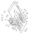
- Fig. 1 shows a magnetic head supporting mechanism 1 disclosed in the above application document.
- the magnetic head supporting mechanism 1 includes a load arm 3 and a load beam 4 (which is also referred to as a flexure).
- the load beam 4 includes a gimbal 5, which has openings (through holes) 6 and 7 having a substantially C shape.
- the gimbal 5 includes a beam 8 supported at both ends in a direction in which the beam 8 traverses the load beam 4, and tongue portions 9 and 10 extending from the beam 8.
- the back surface of the magnetic head slider 11 is formed so that grooves are formed in the width direction of the load beam 4.
- the magnetic head slider 11 can be rotated together with a twist of the beam 8 in a pitching direction indicated by an arrow 12, and can be rotated together with a bend of the beam 8 in a rolling direction indicated by an arrow 13.
- the resonance point (frequency) of vibration of the twist and bend of the beam 8 will greatly becomes lower, and it becomes likely that the degree of flying of the magnetic head slider 11 is varied.
- the width W of the load beam 4 increases, and hence the resonance frequency of vibration of the load beam 4 itself will becomes lower. Thus, the flying magnetic head slider 11 becomes unstable.
- the slider is affected by the stiffness of the lead wires and may cause the slider to fly in the tilt state.
- MR head magneto-resistive effect type head
- four lead wires equal to twice the number of lead wires for the conventional recording/reproducing head are needed.
- Use of the four lead wires increases the influence of the stiffness of the lead wires. This degrades not only the reliability of the flying head but also the read/write characteristics. Hence, the magnetic disk drive does not have a satisfactory reliability.
- a more specific object of the present invention is to provide a magnetic head supporting mechanism capable of stably maintaining a magnetic head slider in the flying state.
- a magnetic head supporting mechanism comprising: a head positioning actuator (223) having an arm (22); and a load beam (21) connected to said arm.
- the load beam has a gimbal (25) comprising: a magnetic head slider fixing portion (30) on which a magnetic head slider (35) having a magnetic head is mounted; a first pair of beams (31, 32) extending from opposite sides of the magnetic head slider fixing portion along a traverse direction (38) of the load beam perpendicular to a longitudinal direction (37) thereof; and a second pair of beams (33, 34) respectively connected to the first pair of beams and extending along said opposite sides of the magnetic head slider fixing portion.
- the first pair of beams extends in the longitudinal direction, and the second pair of beams extends in the traverse direction.
- a magnetic head supporting mechanism comprising: a head positioning actuator (223) having an arm (22); and a load beam (21) connected to said arm.
- the load beam having a gimbal (51) comprises: a magnetic head slider fixing portion (30) on which a magnetic head slider (35) having a magnetic head is mounted; a first pair of beams (31, 32) extending from opposite sides of the magnetic head slider fixing portion along a longitudinal direction of the load beam perpendicular to a traverse direction thereof; and a second pair of beams (33, 34) respectively connected to the first pair of beams and extending along said opposite sides of the magnetic head slider fixing portion.
- Another object of the present invention is to provide a magnetic disk drive having the above-mentioned magnetic head supporting mechanism.
- Fig. 3 shows a 3.5-inch type magnetic disk drive 220 to which the magnetic head supporting mechanism 20 is applied.
- the magnetic disk drive 220 has an enclosure 221 in which a 3.5-inch magnetic disk 222, a head positioning actuator 223 and other parts are housed.
- a load beam 21 made of stainless steel is fixed to an arm 22 of the actuator 223.
- the load beam 21 has a curved bent portion 23 generating elasticity.
- the curbed portion 23 of the load beam 21 is also referred to as an elastic portion 23 in the following description.
- the load beam 21 has a stiffness portion 24 extending from the elastic portion 23, and ribs 21a.
- the elastic portion 23 provides a magnetic head slider 35 with a load in a direction in which the magnetic head slider 35 moves and comes into contact with a magnetic disk 222.
- the load beam 21 has a uniform thickness of, for example, approximately 25 ⁇ m equal to one-third of the thickness of a load beam of a 3380-type (IBM) head supporting mechanism.
- IBM 3380-type
- the width W1 of the load beam 21 is as small as possible, desirably 4 mm or less. This is because the resonance frequency of vibration of the load beam 21 is prevented from becoming down.
- a gimbal 25 is formed in the load beam 21.
- the gimbal 25 includes a pair of C-shaped openings 26 and 26 facing each other in the longitudinal direction of the load beam 21.
- Two slits 28 and 29 are formed in the load beam 21 along respective sides of the load beam 21.
- the gimbal 25 includes a magnetic slider fixing portion 30, a first pair of beam portions 31 and 32, and a second pair of beam portions 33 and 34.
- the magnetic head slider 35 is a light weight structure type slider, which has been proposed in Japanese Patent Laid-Open Application No. 4-228157.
- the proposed slider has a flat back surface opposite to a disk facing surface.
- the flat back surface of the slider is fixed to the fixing portion 30 by means of an adhesive.
- the slider 35 is located so that the center thereof corresponds to the center of the fixing portion 30. It is also possible to use other types of sliders.
- the beam portions 31 and 32 extend outwardly from the respective sides of the fixing portion 30 along a line (load beam width direction line) 38, which passes through the center of the fixing portion 30 (the above center is also the center of the slider 35), and crosses a longitudinal center line 37 of the load beam 21 at a right angle.
- Each of the beam portions 31 and 32 has a length 1 1 .
- the beam portion 33 extends from the beam portion 31 towards the respective sides of the beam portion 31 so that the beam portion 33 crosses the beam portion 31 at a right angle and extends in parallel with the line 37.
- the beam portion 34 extends from the beam portion 32 towards the respective sides of the beam portion 32 so that the beam portion 34 crosses the beam portion 32 at a right angle and extends in parallel with the line 37.
- the beam portion 33 is joined to portions 40 and 41 of the load beam 21 in the periphery of the gimbal 25.
- the beam portion 34 is joined to portions 42 and 43 of the load beam 21 in the periphery of the gimbal 25.
- the beam portion 33 extends from the portions 40 and 41 of the gimbal 25, and the beam portion 34 extends from the portions 42 and 43 of the gimbal 25.
- the distance between the center of the beam portion 33 and one of the two ends thereof is 1 2 .
- the distance between the center of the beam portion 34 and one of the two ends thereof is also 1 2 .
- the beam portion 33 and the beam portion 31 form a T-shaped beam 39A.
- the beam portion 34 and the beam portion 32 form a T-shaped beam 39B.
- the beam portions 31, 32, 33 and 34 form an H-shaped beam. It will be noted that the fixing portion 30, the first pair of beams 31 and 32, and the second pair of beams 33 and 34 are portions of the load beam 21.
- the length 1 1 of the first pair of beams 31 and 32 is limited by the width W1 of the load beam 21.
- the width W1 of the load beam 21 As the width W1 of the load beam 21 is increased, the resonance frequency of a bend and twist of the load beam 21 becomes lower, and the flying characteristics of the slider 35 are degraded. For these reasons, the width W1 cannot be increased.
- the second pair of beams 33 and 34 is formed so that 1 2 > 1 1 . That is, each of the T-shaped beams 39A and 39B has a leg portion and an arm portion longer than the leg portion.
- the magnetic head slider 35 When a waviness of the magnetic disk being rotated occurs or dust adheres to the magnetic disk, the magnetic head slider 35 is rotated in a pitching direction indicated by an arrow 44 in a state in which the first pair of beams 31 and 32 and the second pair of beams 33 and 34 are bent. At this time, a twist deformation occurs in the first pair of beams 31 and 32 of the gimbal 25, and a bend deformation occurs in the second pair of beams 33 and 34.
- the magnetic head slider 35 is rotated in a rolling direction also. At this time, bend deformations occur in the beams 31 and 32 in the respective directions opposite to each other, and bend deformations occur in the beams 33 and 34 in the respective directions opposite to each other.
- Fig. 4 shows a resonance mode of the first-order bend. A deformation occurs in the elastic portion 23 formed at the root of the load beam 21, and the first pair of beams 31 and 32 and the second pair of beams 33 and 34 are deformed in the same direction.
- Fig. 5 shows a resonance mode of the first-order twist.
- a twist deformation occurs in the elastic portion 23 formed at the root of the load beam 21 in such a manner so the right and left portions of the elastic portion 23 have different heights.
- the beam located on the right side of the gimbal 25 is deformed so as to be formed into a convex shape facing upwards.
- the beam located on the left side of the gimbal 25 is deformed so as to be shaped into a convex facing downwards.
- a composite type magnetic head 48 and four terminals 100A, 100B, 100C and 100D are provided in the magnetic head slider 35.
- the magnetic head 48 includes an MR head for reproduction and an interactive type head for recording, these heads being integrated with each other.
- the magnetic head 48 is located at a rear end surface of the magnetic head slider 35 in a relative movement direction 46 with respect to the magnetic disk 222.
- lead wires 15A, 15B, 15C and 15D are connected to the terminals 100A, 100B, 100C and 100D, respectively.
- Each of the lead wires 15A through 15D has a diameter of, for example, 30 ⁇ m.
- the lead wires 15A - 15D are laid on the side opposite to the side on which the magnetic head slider 35 is mounted, and are attached to a center portion 36 of the fixing portion 30 by means of an adhesive 16. Further, the lead wires 15A - 15D extend along the longitudinal center line 37 of the load beam 21 towards the base portion of the load beam 21, and are fixed thereto at two points by means of the adhesive 16.
- Reference numbers 17 -1 , 17 -2 and 17 -3 respectively indicate a first fixing point, a second fixing point and a third fixing point at which the lead wires 15A through 15D are fixed by means of the adhesive 16.
- the first fixing point 17 -1 moves in accordance with movement of the magnetic head slider 35. Hence, it is unnecessary to be concerned about the stiffness of portions of lead wires 15A through 15D between the terminals 100A - 100D and the first fixing point 17 -1 and to provide additional lengths of the lead wires 15A - 15D. In Fig. 6, such additional lengths of the lead wires 15A - 15D are not provided.
- the distance between the first fixing point 17 -1 and the second fixing point 17 -2 is long, and the stiffness of the lead wires 15A - 15B between the fixing points 17 -1 and 17 -2 little affects the rotation stiffness of the gimbal 25.
- the magnetic head supporting mechanism 20 has the following features. First, the rotation stiffness of the gimbal 25 is considerably small because of the characteristics of the T-shaped beams. Second, the gimbal 25 is supported at the four points 40 - 43, and hence, the resonance frequency of vibration of the gimbal 25 is high even when the second pair of beams 33 and 34 is long. Third, the end of the load beam 21 can be formed so that it has a small width W1, and hence the resonance frequency of vibration of the load beam 21 is high. Fourth, the flying stability of the magnetic head slider 35 is excellent due to the above first, second and third features. The fifth feature of the mechanism 20 is such that the first pair of beams 31 and 32 has a short length 1 1 and is formed in the same plane.
- the first pair of beams 31 and 32 has a large strength with respect to force received in the contact start/stop operation, and a shear failure does not easily occur in the beams 31 and 32.
- the sixth feature of the mechanism 20 is such that the stiffness of the lead wires 15A - 15D does not affect the rotation stiffness of the gimbal 25.
- the gimbal 25 is formed so that a pair of T-shaped beams (which form an H-shaped beam) is provided with respect to the center of the gimbal 25, and hence a low rotation stiffness and a high resonance frequency are achieved. More specifically, the rotation stiffness of the mechanism 20 becomes one-third of that of the aforementioned IBM 3380 type head supporting mechanism, while the resonance frequency of the mechanism 20 is as high as that of the IBM 3380 type head supporting mechanism. As a result, it becomes possible to stably fly a compact slider having a low airbearing stiffness.
- Tables 1 and 2 show characteristics of the head supporting mechanism 20 according to the first embodiment of the present invention supporting a 2mm-length slider, and the IBM 3380 type head supporting mechanism supporting which a 3.2mm-length slider.
- Table 1 COMPARISON OF STIFFNESS(static characteristics by computer simulation) Stiffness 1st embodiment 3380 type pitch stiffness 1.5 grf cm/rad 9.4 grf cm/rad roll stiffness 1.5 grf cm/rad 5.1 grf cm/rad up/down stiffness 0.55 grf/mm 2.4 grf/mm equivalent weight ratio 0.74 0.72
- Table 2 COMPARISON OF RESONANCE FREQUENCY (dynamic characteristic by computer simulation) Stiffness 1st embodiment 3380 type 1st bend 2.1 kHz 2.1 kHz 1st twist 2.3 kHz 2.6 kHz in-plane 8.5 kHz 5.7 kHz
- the total length of the supporting mechanism is short (10 mm), which is approximately half of that of the IBM 3380 type mechanism.
- the thickness of the load beam 21 of the first embodiment is 25 ⁇ m, which is approximately one-third of that of the IBM 3380 type mechanism.
- Table 1 shows data obtained by a computer simulation. More specifically, Table 1 shows the pitch stiffness and roll stiffness of the gimbal 25 of the first embodiment, and the up/down stiffness of the load beam 21 thereof. Further, Table 1 shows the pitch stiffness and the roll stiffness of the gimbal of the IBM 3380 type mechanism, and the up/down stiffness of the load beam thereof. It can be seen from Table 1 that the rotation stiffness equal to one-third of the gimbal of the IBM 3380 type mechanism can be obtained by optimizing the width and length of the grooves in the gimbal 25.
- Table 2 shows the resonance frequencies of the first embodiment and the conventional IBM 3380 type mechanism obtained by a computer simulation.
- the resonance frequencies of the first embodiment are similar to those of the IBM 3380 type mechanism.
- the magnetic head supporting mechanism according to the first embodiment of the present invention has a low stiffness and a high resonance frequency.
- Fig. 8 shows a magnetic head supporting mechanism 50 according to the second embodiment of the present invention.
- the mechanism 50 includes a gimbal 51.
- the gimbal 51 is formed so that the gimbal 25 shown in Fig. 2 is rotated about the center 36 by 90°.
- Two T-shaped beams 52 and 53 are arranged in the longitudinal direction of the load beam 21.
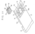
- Fig. 9 shows a magnetic head supporting mechanism 60 having a gimbal 61 according to a third embodiment of the present invention.
- the gimbal 61 has the aforementioned first pair of beams 31 and 32, and a second pair of beams 33A and 34A.
- the beam 33A and the beam 31 form an acute angle ⁇ .
- the beam 34A and the beam 32 form an acute angle equal to the acute angle ⁇ .
- the rotation stiffness of the gimbal 61 is less than that of the gimbal 25 shown in Fig. 2.
- the magnetic head slider 35 in the third embodiment can be more stably flied than that in the first embodiment shown in Fig. 2.
- FIG. 10 shows a magnetic head supporting mechanism 70 having a gimbal 71 according to a fourth embodiment of the present' invention.
- a magnetic head slider 35A of the mechanism 70 includes flanges 72 and 73 formed on the respective sides of the slider 35A.
- a magnetic head slider fixing portion 30A of the gimbal 71 includes an opening 74 having a size corresponding to the magnetic head slider 35A.
- the opening 74 is of a rectangular shape defined by a rectangular frame 76.
- the magnetic head slider 35A engages the opening 74, and the flanges 72 and 73 are made to adhere to the frame 76 by means of an adhesive. In this manner, the magnetic head slider 35A is fixed to the magnetic head slider fixing portion 30A.
- the center G of gravity of the magnetic head slider 35A is substantially located on the surface of the load beam 21.
- the magnetic head slider 35A is moved by exerting a force on the center G of gravity.
- unnecessary rotation force about the center G of gravity of the magnetic head slider 35A does not occur, and the unbalance of the magnetic head slider 35A is reduced.
- the magnetic head slider 35A can be stably flied in the seek operation.
- the height of the magnetic head assembly can be reduced. Hence, it is possible to laminate layers of the head at reduced intervals and to provide an increased number of disks per unit length. As a result, it is possible to increase the volume storage density of the magnetic disk drive and hence the storage density.
- Fig. 12 shows a magnetic head supporting mechanism 80 having a magnetic head slider 35B according to a fifth embodiment of the present invention.
- the magnetic head slider 35B has a flange 81 formed around the circumference thereof.
- the magnetic head slider 35B engages the opening 74, and the flange 81 is made to adhere to the magnetic head slider fixing portion 30A by means of an adhesive.
- the fifth embodiment of the present invention differs from the fourth embodiment thereof in that the whole circumference of the magnetic head slider 35B is made to adhere to the fixing portion 30A.
- the adhesive strength is increased and the reliability of the magnetic head supporting mechanism is improved.
- Fig. 13 shows a magnetic head supporting mechanism 90 according to a sixth embodiment of the present invention.
- Fig. 14 shows a free end of a load beam of the magnetic head supporting mechanism 90.
- the mechanism 90 is designed so that it does not have any influence of the stiffness of lead wires, which affect flying of the slider having a low airbearing stiffness.
- each of the lead wires has a diameter of 30 ⁇ m and has an additional length (free length) of 1 mm
- the rotation stiffness of the gimbal is approximately five times that of the gimbal in which there is no lead wire. This degrades the flying stability of the slider.
- the magnetic head supporting mechanism 90 has wiring patterns 91, 92, 93 and 94, which are formed by patterning a copper thin film formed by, for example, plating by means of the photolithography technique.
- the wiring patterns 91 - 94 extend on a central portion of the lower surface of the load beam 21 in the longitudinal direction.
- Each of the wiring patterns 91 - 94 is approximately 5 ⁇ m thick and 50 ⁇ m wide. The thickness and width of the wiring patterns depend on the resistance of the conductive pattern and the capacity of the load beam 21.
- Terminals 95A - 95D made of copper are formed on the base portion of the load beam 21. Further, terminals 96A - 96D are formed in a terminal area 30a of the magnetic head slider fixing portion 30 of the gimbal 25.
- the tops of the terminals 95A - 95D and 96A - 96D are plated by, for example, Au. This plating contributes to preventing exposure of copper and improving the bonding performance.
- Ends of the wiring patterns 91, 92, 93 and 94 are respectively connected to the terminals 95A, 95B, 95C and 95D.
- the other ends of the two wiring patterns 91 and 92 extend along the beams 33A and 31, and are connected to the terminals 96A and 96B, respectively.
- the other ends of the wiring patterns 93 and 94 extend along the beams 34A and 32 and are connected to the terminals 96C and 96D, respectively.
- the wiring patterns 91, 92, 93 and 94 are electrically insulated from the load beam 21 by means of an insulating film 97, and are covered by a protection film 98.
- the insulating film 97 and the protection film 98 are made of photosensitive polyimide and are grown to a thickness of approximately 5 ⁇ m.
- the insulating film 97 and the protection film 98 are respectively patterned by the photolithography technique.
- the thickness of the insulating film 97 is determined on the basis of a capacitance between the conductive pattern (made of Cu) and the load beam (made of stainless steel).
- polyimide has heat-resistance enough for an annealing process. Since polyimide has photosensitivity, it can be easily patterned. Further, the polyimide films 97 and 98 have corrosion resistance, and excellent reliability.
- terminals 95A - 95D and 96A - 96D are etched because these terminals are not covered by the protection film 98.
- the surfaces of these terminals are covered by an Au film (not shown) having a thickness of approximately 1 ⁇ m formed by plating or vapor deposition.
- the magnetic head slider 35 is made to adhere to the fixing portion 30 by means of an adhesive.
- the terminals 96A - 96D are located at a right angle with respect to terminals 100A - 100D of the magnetic head 48 formed on the end surface of the magnetic head slider 35, and are respectively connected to the terminals 100A - 100D by means of Au balls 101A - 101D.
- the Au balls 101A - 101D are formed by means of, for example, a gold ball bonder device.
- the terminals 96A - 96D and terminals 100A - 100D are located as shown in Fig. 16.
- the terminals 100A - 100D are long in the direction of the height of the magnetic head slider 35 and are located so that these terminals 100A - 100D face the terminals 96A - 96D in the state where the head slider 35 is fixed to the fixing portion 30.
- the wiring patterns 91 - 94 bypass holes 102A, 102B and 102C, as shown in Fig. 13 and extend up to an area close to the head slider 35.
- the hole 102C is used to fix the load beam 21 to the arm 22 (not shown in Fig. 13).
- the holes 102A, 102B and 102C are used so that a tool is inserted therein.
- dummy patterns 103A - 103D and 104A - 104D are provided so that these dummy patterns are symmetrical to the bypassing portions of the wiring patterns 91 - 94 with respect to the holes 102A and 102B.
- the insulating film 97 and the protection film 98 are provided for the dummy patterns 103A - 103D and 104A - 104D in the same manner as the wiring patterns 91 - 94.
- the dummy patterns 103A - 103D and 104A - 104D are provided in order to balance the mechanical stiffness of the load beam 21 in the direction of the width of the load beam 21.
- the wiring patterns 91 - 94 are arranged so that these patterns form a loop.
- This loop functions as an antenna, which receives noise components contained in the head signals.
- the degree of the noise components is increased.
- the wiring patterns 91 and 92 respectively connected to the terminals 96A and 96B are arranged between the hole 102A and the magnetic head slider 35, and all the wiring patterns 91 - 94 are gathered in the vicinity of the hole 102A.
- the dummy patterns 104A - 104D are formed. For the same reason as above, the dummy patterns 103A - 103D are formed in the vicinity of the hole 102B.
- auxiliary films 106 and 107 having a belt shape are formed along the right and left ends of the load beam 21.
- the auxiliary films 106 and 107 are provided in order to receive a clamping force generated when the load beam 21 is clamped in a bending process which will be described later. Such a clamping force is also received by the wiring patterns 91 - 94.
- the clamping force is distributed so that the clamping force is exerted on not only the wiring patterns 91 - 94 but also the auxiliary films 106 and 107. Hence, it is possible to prevent the wiring patterns 91 - 94 from being damaged.
- a convex dummy pattern 108 is provided in order to prevent an adhesive from flowing from the fixing portion 30 when the slider 35 is fixed to the fixing portion 30 and to prevent the slider 35 from being tilted due to the thickness of the wiring patterns. More particularly, the convex pattern 108 is used to form a groove in which adhesive used to fix the slider 35 is saved between the pattern 108 and the terminals 96A - 96D. Further, the convex pattern 108 is designed to have the same height as the patterns having the terminals 96A - 96D. If the dummy pattern 108 is not used, the slider 35 will be inclined with respect to the fixing portion 30 due to the height of the terminals 94A - 94D.
- the convex pattern 108 can be formed by a cooper-plated thin film similar to the wiring patterns 91 - 94.
- the protection film 98 covers the convex pattern 108.
- the adhesive is provided on a step part between the wiring patterns and the convex pattern 108.
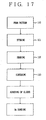
- the load beam 21 is produced by a process shown in Fig. 17.
- a pattern formation step 110 is performed. More particularly, photosensitive polyimide is coated on a stainless plate.
- the insulating film 97 is formed by the photolithography technique.
- a copper film is formed by the plating process, the vapor deposition process or the like, and is patterned into the wiring patterns 91 - 94 by the photolithography technique.
- photosensitive polyimide is coated and is patterned into the protection film 98 and the auxiliary films 106 and 107 by the photolithography technique.
- Polyimide can be coated by a spin-coat process, and is patterned and etched.
- a thin film, such as a Cr film can be formed in order to improve the adhesiveness between the insulating film and the Cu film and between the Cu film and the protection film and to improve the reliability of the adhesion.
- etching step 111 is performed in order to form the openings 26 - 29 and the holes 102A - 102C and the outward form of the load beam in the stainless plate.
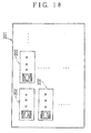
- Fig. 18 shows load beams 202 before punching for cutting off bridge portions (not shown) to provide pieces, so that the load beams 202 are formed in a stainless plate 201 and arranged in rows and columns.
- a bending step 112 is performed by bending the respective ends of each of the load beams 202 formed in the stainless plate 201, so that ribs 21a are formed.
- the bending step 112 can be performed by press so that the load beams 202 are processed at the same time.
- an annealing step 113 is performed at a temperature of approximately 400 °C, so that internal stress can be removed. Further, a slider adhering step and an Au bonding step can be automatically carried out before the load beams 202 are punched. Hence, it is possible to automatically perform the production process shown in Fig. 17 and reduce the number of steps and the cost thereof.
- the load beam 21 can be produced without performing the annealing step 113.
- the pattern formation step 110 and the etching step 111 are performed, and subsequently the slider adhering step and the Au bonding step are carried out. Thereafter, the bending step 112 is carried out to form the ribs 21a.
- the magnetic head slider 35 has the aforementioned two terminals 100A and 100B.
- the two wiring patterns 91A and 92A are provided so that these wiring patterns extend on only the beams 32 and 34A, while two dummy patterns 210 and 211 are provided so as to extend on the beam 31 and 33A in order to balance the mechanical stiffness of the load beam 21 in the direction of the width of the load beam 21.
- the magnetic head supporting mechanism 90 has the following features.
- the wiring patterns 91 - 94 are formed on the load beam 21, it is not necessary to provide tubes for passing the lead wires through the load beam 21. Hence, it is possible to prevent unbalanced force caused by the lead wires and tubes from being exerted on the magnetic head slider 35 and to stably fly the magnetic head slider 35.
- the rotation stiffness of the load beam 21 does not have polarity. Hence, the magnetic head slider can be flied stably.
- the crimp connection using the Au balls 101A - 101D enables automatic assembly and non-bire bonding between head terminals and pattern terminals.
- the beams may be curved.
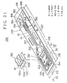
- Fig. 21 shows a back surface of a magnetic head supporting mechanism 230 according to the seventh embodiment of the present invention.
- Fig. 22 shows a 1.8-inch-type magnetic disk drive 231 to which the magnetic head supporting mechanism 230 is applied.
- the magnetic disk drive 231 has an enclosure 232 having almost the same dimensions as those of an IC memory card. In the enclosure 232, provided are a magnetic disk 233 having a diameter of 1.8 inches, and an actuator to which two sets of magnetic head supporting mechanisms are attached.
- the magnetic disk drive 231 is more compact than the magnetic disk drive 220 shown in Fig. 3.
- a magnetic head slider 35C is made compact in accordance with light-sizing of the magnetic disk drive 231. More particularly, dimensions a x b of the magnetic head slider 35C are 0.8 mm x 1.0 mm, and are approximately one-quarter the area of the magnetic head slider 35 shown in Fig. 2. In order to stably fly the compact magnetic head slider 35C, it is necessary to considerably reduce the stiffness without decreasing the resonance frequency, as compared with the magnetic head supporting mechanism 30.
- a load beam 235 shown in Fig. 21 is made of stainless, and has a base portion fixed to an arm 236 of the actuator 234 (see Fig. 22).
- the load beam 235 has a width W2 of approximately 2 mm, a length L of approximately 9 mm, and a thickness to of approximately 25 ⁇ m, and is approximately a half of the volume of the load beam 21 shown in Fig. 2.
- the load beam 235 is diminished, and hence the resonance frequency of bending which will be described later is high.
- the load beam 235 is a sheet-shaped piece, and a flat plate piece to which a bending process has not been subjected. Hence, there is no problem of a bending process error which degrades the flying stability of the magnetic head slider.
- the load beam 235 includes a load beam main body 237 and a gimbal 238 located on the end side of the load beam 235.
- the gimbal 238 has a substantially U-shaped opening (through hole) 239 formed in the load beam 235.
- the gimbal 238 includes a magnetic head slider fixing portion 240, a first beam 241, a second beam 242, a third beam 244, and a connecting portion 243.
- the magnetic head slider fixing portion 240 has a size corresponding to the magnetic head slider 35C.
- the first beam 241 and the second beam 242 extend along respective longitudinal ends of the load beam 235 from the end thereof.
- the connecting portion 243 extends in the direction of the width of the load beam 235, and connects the first beam 241 and the second beam 242 together.
- the third beam 244 extends from the connecting portion 243 to the magnetic head slider fixing portion 240 in the longitudinal direction of the load beam 235.
- the magnetic head slider fixing portion 240 is connected to the main body 237 of the load beam 235 via the third beam 244, the connecting portion 243 and the first and second beams 241 and 242. Hence, the rotation stiffness of the load beam 230 can be reduced to a small value due to bending of the whole beams.
- holes 245, 246 and 247 with which a tool is engaged, and a pair of slits 248 and 249 are formed in the main body 237 of the load beam 235. Adjustment slits 248 and 249 are used to reduce the rotation stiffness of the load beam.
- the holes 245, 246 and 247 and the slits 248 and 249 are formed by etching.
- the connectors 95A - 95D, 96A - 96D and the wiring patterns 91 - 94 are formed symmetrically with respect to the longitudinal direction of the load beam 235.
- the magnetic head slider 35C is made to adhere to the fixing portion 240, and the terminals 96A - 96D and 100A - 100D are respectively connected to each other by means of Au balls as in the case shown in Fig. 16.
- the structure shown in Fig. 21 does not use dummy patterns because the length and the width of the load beam 235 are less than those of the load beam shown in Fig. 13 and the loop formed by the wiring patterns is smaller than that shown in Fig. 13. However, it is preferable to arrange the wiring patterns and provide the dummy patterns as shown in Figs. 13 and 14 in order to reduce the noise from the heads.
- the free end of the arm 236 is bent so that a substantially V-shaped cross section of the arm 236 is formed in which the "V" is inverted.
- the free end of the arm 236 has an upward slant portion 236a and a downward slant portion 236b declined at an angle ⁇ with respect to the horizontal direction.
- the magnetic disk drive 231 uses two magnetic head supporting mechanisms 230 so that the single magnetic disk 233 is sandwiched between the mechanisms 230.
- the load beam 235 causes the magnetic head slider 35C to come into contact with the magnetic disk 233 when the magnetic disk 233 is not being rotated.
- the main body 237 of the load beam 235 is caused to be bent and elastically deformed.
- the elastic force stored in the main body 237 of the load beam 235 generates a load Fl, which urges the magnetic head slider 35C towards the magnetic disk 233.
- a wide gap 250 can be formed between an end 236c of the arm 236 and the magnetic disk 233, as compared with a case indicated by a two-dot chained line in which the arm 236 is simply bent downwards.
- the main body 237 of the load beam 235 and the third beam 244 are bent.
- a moment is exerted by a center 251 of the magnetic head slider 35C.
- a moment M1 directed counterclockwise is exerted by the load beam main body 237 and the first and second beams 241 and 242.
- a moment M2 directed clockwise is exerted on the third beam 244.
- the dimensions of the load beam 235 are selected so that the moments M1 and M2 are balanced.
- the load beam 235 is 9 mm long, and the gimbal 238 is 2.5 mm long.
- the length and width of the main body 235 of the load beam 237 are 5.7 mm and 2 mm, respectively.
- the magnetic head slider 35C is rotated in the pitching direction indicated by arrow 44 in such a manner that the first, second and third beams 241, 242 and 244 and the load beam main body 237 are bent. At this time, all the beams 241, 242 and 244 are bent so as to be deformed in the form of arch shapes.
- the gimbal 238 is bent and hence the load beam main body 237 is bent. Hence, the pitch stiffness can be greatly reduced.
- the magnetic head slider 35C is rotated in the rolling direction indicated by arrow 45 in such a manner that the first and second beams 241 and 242 are respectively bent in the opposite directions and the load beam main body 237 is twisted. At this time, the gimbal 238 is bent and hence the load beam main body 237 is bent. Hence, the rolling stiffness can be greatly reduced.
- the load beam 235 is bent and deformed, as shown in Fig. 26. More specifically, the load beam main body 237, and the first, second and third beams 241, 242 and 244 of the gimbal 238 are bent as shown in Fig. 24.
- the overall load beam 235 is formed flexibly, but the resonance frequency of the first-order bend is high, while the stiffness is small.
- the load beam 235 is twisted as shown in Fig. 27.
- the gimbal 238 is deformed and hence the load beam main body 237 is deformed.
- the overall load beam 235 is flexibly formed, but the resonance frequency of the first-order twist is high while the stiffness thereof is low.
- Tables 3 and 4 show characteristics of the magnetic head support mechanism 230 according to the seventh embodiment of the present invention and the magnetic head supporting mechanism 30 of the first embodiment thereof shown in Fig. 2.
- Table 3 COMPARISON OF STIFFNESS (static characteristics by computer simulation) Stiffness 7th embodiment 1st embodiment pitch stiffness 0.44 grf cm/rad 1.5 grf cm/rad roll stiffness 0.24 grf cm/rad 1.5 grf cm/rad up/down stiffness 0.36 grf/mm 0.55 grf/mm equivalent weight ratio 0.76 0.74
- Table 4 COMPARISON OF RESONANCE FREQUENCY (dynamic characteristic by computer simulation) Stiffness 7th embodiment 1st embodiment 1st bend 1.6 kHz 2.1 kHz 1st twist 4.4 kHz 2.3 kHz in-plane 7.1 kHz 8.5 kHz
- Table 3 the pitch stiffness, the roll stiffness, and the up/down stiffness of the load beam 235 obtained by means of a computer simulation. It can be from Table 3 that the pitch stiffness and the roll stiffness of the seventh embodiment of the present invention are approximately one-quarter of those of the first embodiment thereof.
- Table 4 shows the resonance frequencies of the first and seventh embodiments of the present invention obtained by a computer simulation. It can be seen from Table 4 that the first-order bend resonance frequency, the first-order twist resonance frequency and the lateral resonance frequency are kept very high.
- the magnetic head supporting mechanism 230 according to the seventh embodiment of the present invention has a resonance frequency as high as that of the magnetic head supporting mechanism 30 according to the first embodiment, and stiffness much less than that of the mechanism 30. Hence, the compact magnetic head slider 35C can be stably flied.
- the base portion of the load beam 237 is bent, so that the load beam is supported in the same manner as shown in Fig. 2 and the load Fl shown in Fig. 24 is obtained.
- the load beam is supported in the same manner as shown in Fig. 2 and the load Fl shown in Fig. 24 is obtained.
- only portions 255 and 256 outside of the slits 248 and 249 are bent. Hence, unnecessary strain is not exerted on the wiring patterns 91 - 94 located between the slits 248 and 249.
- a first variation of the gimbal 238 of the load beam 235 will be described.
- a gimbal 238 -1 shown in Fig. 28 has a first beam 244 -1 having a long width A, and an opening 239 -1 having a long length B.
- First and second beams 241 -1 and 242 -1 are long.
- Fig. 29 shows a second variation 238 -2 of the gimbal 238.
- the gimbal 238 -2 has first and second beams 241 -2 and 242 -2 each having a small width C.
- Fig. 30 shows a third variation 238 -3 of the gimbal 238.
- the gimbal 238 -3 has first and second variations 241 -3 and 242 -3 having a large width D.
- Fig. 31 shows a fourth variation 238 -4 of the gimbal 238.
- the gimbal 238 -4 has a fourth beam 260 connecting the center of the end of the magnetic head slider fixing portion 240 and the load beam main body 237 together.
- the fourth beam 260 functions to prevent a deformation of the magnetic head slider fixing portion 240, but increases the rotation stiffness. Hence, it is desired that the width of the fourth beam 260 be as small as possible and the length thereof are as long as possible.
- Fig. 32 shows a fifth variation 238 -5 of the gimbal 238.
- the gimbal 238 -5 has first and second arch-shaped beams 241 -5 and 242 -5 .
- a bent connecting plate 261 is fixed to an arm 236A, and the load beam 235 is fixed to the connecting plate 261. Hence, it is not necessary to subject the arm 236A to the bending process.
- the third beam 244 shown in Fig. 21 has the same width as the fixing portion 240 and is integrated with the fixing portion 240.
- the load applied to the magnetic head slider is generated by bending the spring portion of the load beam.
- the arm fixing structure used in the seventh embodiment of the present invention in which the spring portion is kept flat.
Abstract
- a head slider fixing portion on which the head slider is mounted;
- first and second beams extending along a longitudinal direction of said head supporting assembly, said first and second beams being spaced apart and entirely separated from the head slider fixing portion;
- a third beam which connects an end of the head supporting assembly to a first end of the head slider fixing portion;
- wiring patterns attached to at least one of said first, second and third beams; and
- teminals formed on the head slider fixing portion and connected to said wiring patterns,
- wherein said wiring patterns are attached to a side of said head supporting assembly on which said head slider is located.
Description
- The present invention relates to a magnetic head supporting mechanism used for a magnetic disk drive.
- A magnetic head slider on which a magnetic head is mounted is attached to a free end of a load beam, and is maintained, during a recording/reproducing operation, in a state in which the magnetic head slider flies above a magnetic disk.
- Recently, it has been required to improve an HDI (Head Disk Interface) characteristic, which is one of the parameters describing the reliability of magnetic disk drives. In order to meet the above requirement, it is effective to diminish the magnetic head slider or reduce a spring force urging the magnetic head slider towards the magnetic disk.
- The following event will occur when the magnetic head slider is diminished. It is necessary to reduce the size of a supporting spring which holds the magnetic head slider as the slider is reduced in size. This is intended to keep the follow-up characteristic with respect to waviness of the disk and maintain the flying stability of the head. The following event will occur when the spring force on the head slider is reduced. That is, the flying stiffness of the head is degraded due to reduction of the spring force on the head slider. Further, assembly errors are increased because parts, such as a slider and a supporting spring are diminished. With the above in mind, it is necessary for a device for supporting a magnetic head slider to have a mechanism capable of sufficiently ensuring the flying stability of the magnetic head slider.
- Conventionally, the magnetic head supporting mechanism is made up of a load beam, a gimbal fixed to the load beam, and a magnetic head slider fixed to the gimbal. With the above structure, it is more difficult to assemble (position) these parts as the size of the parts is reduced. When there is an assembly error, the magnetic head slider is maintained in an unbalance flying state in which the slider flies in a tilted state. Hence, the reliability of the flying head is degraded and further the read/write characteristics are also degraded. As a result, the reliability of the magnetic disk drive is degraded.
- In order to eliminate the factors causing the unbalanced flying due to the assembly error of the head supporting mechanism, Japanese Patent Laid-Open Application No. 3-189976 proposes an improvement in which an integrally formed supporting spring corresponding to the conventional load beam and gimbal is used and assembly is no longer needed.
- Fig. 1 shows a magnetic
head supporting mechanism 1 disclosed in the above application document. The magnetichead supporting mechanism 1 includes aload arm 3 and a load beam 4 (which is also referred to as a flexure). The load beam 4 includes agimbal 5, which has openings (through holes) 6 and 7 having a substantially C shape. Further, thegimbal 5 includes a beam 8 supported at both ends in a direction in which the beam 8 traverses the load beam 4, andtongue portions 9 and 10 extending from the beam 8. The back surface of themagnetic head slider 11 is formed so that grooves are formed in the width direction of the load beam 4. - The
magnetic head slider 11 can be rotated together with a twist of the beam 8 in a pitching direction indicated by anarrow 12, and can be rotated together with a bend of the beam 8 in a rolling direction indicated by anarrow 13. - It is necessary to reduce the rotation stiffness of the
gimbal 5 in order to ensure the flying stability of the compact magnetic head slider. Further, it is impossible to reduce the thickness t of thegimbal 5 having the above structure because the load beam 4 needs to be stiff. In order to reduce the rotation stiffness of thegimbal 5 without reducing the thickness t of the load beam 4, it is necessary to lengthen thelength 1 of the beam 8. If the load beam 4 and thegimbal 5 are made to have different thicknesses, it is necessary to a complex process in which only thegimbal 5 is half etched, while the load beam is not processed. However, it is very difficult to obtain a desired precision in thickness by the above process and to obtain desirable characteristics. - If the
length 1 of the beam 8 is increased, the following disadvantages will occur. First, the resonance point (frequency) of vibration of the twist and bend of the beam 8 will greatly becomes lower, and it becomes likely that the degree of flying of themagnetic head slider 11 is varied. Second, the width W of the load beam 4 increases, and hence the resonance frequency of vibration of the load beam 4 itself will becomes lower. Thus, the flyingmagnetic head slider 11 becomes unstable. - Consequently, when the integrally formed supporting spring having the integrated load beam and gimbal is used, it is very difficult to realize a structure of the integrated supporting spring in which only the rotation stiffness is reduced without decreasing the resonance frequency of the gimbal.
- It becomes impossible to neglect the influence of lead wires connected to the head because of degradation of the airbearing stiffness caused by down-sizing of the slider and reduction in the load force on the head slider. More particularly, the slider is affected by the stiffness of the lead wires and may cause the slider to fly in the tilt state. Particularly, when a magneto-resistive effect type head (MR head) is used as a reproduction head, such a head is combined with an interactive type head. Hence, four lead wires equal to twice the number of lead wires for the conventional recording/reproducing head are needed. Use of the four lead wires increases the influence of the stiffness of the lead wires. This degrades not only the reliability of the flying head but also the read/write characteristics. Hence, the magnetic disk drive does not have a satisfactory reliability.
- It is a general object of the present invention to provide a magnetic head supporting mechanism in which the above disadvantages are eliminated.
- A more specific object of the present invention is to provide a magnetic head supporting mechanism capable of stably maintaining a magnetic head slider in the flying state.
- The above objects of the present invention are achieved by a magnetic head supporting mechanism comprising: a head positioning actuator (223) having an arm (22); and a load beam (21) connected to said arm. The load beam has a gimbal (25) comprising: a magnetic head slider fixing portion (30) on which a magnetic head slider (35) having a magnetic head is mounted; a first pair of beams (31, 32) extending from opposite sides of the magnetic head slider fixing portion along a traverse direction (38) of the load beam perpendicular to a longitudinal direction (37) thereof; and a second pair of beams (33, 34) respectively connected to the first pair of beams and extending along said opposite sides of the magnetic head slider fixing portion.
- In an alternative, the first pair of beams extends in the longitudinal direction, and the second pair of beams extends in the traverse direction.
- The above objects of the present invention are also achieved by a magnetic head supporting mechanism comprising: a head positioning actuator (223) having an arm (22); and a load beam (21) connected to said arm. The load beam having a gimbal (51) comprises: a magnetic head slider fixing portion (30) on which a magnetic head slider (35) having a magnetic head is mounted; a first pair of beams (31, 32) extending from opposite sides of the magnetic head slider fixing portion along a longitudinal direction of the load beam perpendicular to a traverse direction thereof; and a second pair of beams (33, 34) respectively connected to the first pair of beams and extending along said opposite sides of the magnetic head slider fixing portion.
- Another object of the present invention is to provide a magnetic disk drive having the above-mentioned magnetic head supporting mechanism.
- Other objects, features and advantages of the present invention will become more apparent from the following detailed description when read in conjunction with the accompanying drawings, in which:
- Fig. 1 is a perspective view of a conventional magnetic head supporting mechanism;
- Fig. 2 is a perspective view of a magnetic head supporting mechanism according to a first embodiment of the present invention;
- Fig. 3 is a plan view of a 3.5-inch magnetic disk drive to which the magnetic head supporting mechanism shown in Fig. 2 is applied;
- Fig. 4 is a perspective view of a first-order bend state of a load beam shown in Fig. 2;
- Fig. 5 is a perspective view of a first-order twist state of the load beam shown in Fig. 2;
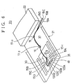
- Fig. 6 is a perspective view of the upper side of the magnetic head supporting mechanism shown in Fig. 2;
- Fig. 7 is a side view of the magnetic head supporting mechanism shown in Fig. 2;
- Fig. 8 is a perspective view of a magnetic head supporting mechanism according to a second embodiment of the present invention;
- Fig. 9 is a perspective view of a magnetic head supporting mechanism according to a third embodiment of the present invention;
- Fig. 10 is a perspective view of a magnetic head supporting mechanism according to a fourth embodiment of the present invention;
- Fig. 11 is a side view of the mechanism shown in Fig. 10;
- Fig. 12 is a perspective view of a magnetic head supporting mechanism according to a fifth embodiment of the present invention;
- Fig. 13 is a perspective view of a magnetic head supporting mechanism according to a sixth embodiment of the present invention;
- Fig. 14 is a plan view of a free-end part of a load beam shown in Fig. 13;
- Fig. 15 is a sectional-view taken along a line XIV-XIV shown in Fig. 13;
- Fig. 16 is a perspective view of a magnetic head slider shown in Fig. 13;
- Fig. 17 is a flowchart of a production process for the load beam shown in Fig. 13;
- Fig. 18 is a plan view of a plate obtained after an etching step shown in Fig. 17 is carried out;
- Fig. 19 is a flowchart of another production process for the load beam shown in Fig. 13;
- Fig. 20 is a perspective view of a variation of the sixth embodiment of the present invention;
- Fig. 21 is a perspective view of a magnetic head supporting mechanism according to a seventh embodiment of the present invention;
- Fig. 22 is a plan view of a magnetic disk drive to which the magnetic head supporting mechanism shown in Fig. 21 is applied;
- Figs. 23A and 23B are respectively plan and side views of the magnetic head supporting mechanism shown in Fig. 21;
- Fig. 24 is a side view of a state observed when the magnetic head supporting mechanism shown in Fig. 21 is provided in the magnetic disk drive;
- Fig. 25 is an emphasized view of the state in Fig. 24;
- Fig. 26 is a side view of a first-order bend state of a load beam used in the seventh embodiment of the present invention;
- Fig. 27 is a side view of a first-order twist state of the load beam used in the seventh embodiment of the present invention;
- Fig. 28 is a plan view of a first variation of a gimbal of the load beam used in the seventh embodiment of the present invention;
- Fig. 29 is a plan view of a second variation of the gimbal of the load beam used in the seventh embodiment of the present invention;
- Fig. 30 is a plan view of a third variation of the gimbal of the load beam used in the seventh embodiment of the present invention;
- Fig. 31 is a plan view of a fourth variation of the gimbal of the load beam used in the seventh embodiment of the present invention;
- Fig. 32 is a plan view of a fifth variation of the gimbal of the load beam used in the seventh embodiment of the present invention; and
- Fig. 33 is a side view of a variation of the seventh embodiment of the present invention.
- A description will now be given, with reference to Fig. 2, of a magnetic
head supporting mechanism 20 according to a first embodiment of the present invention. - Fig. 3 shows a 3.5-inch type
magnetic disk drive 220 to which the magnetichead supporting mechanism 20 is applied. Themagnetic disk drive 220 has anenclosure 221 in which a 3.5-inchmagnetic disk 222, ahead positioning actuator 223 and other parts are housed. - A
load beam 21 made of stainless steel is fixed to anarm 22 of theactuator 223. Theload beam 21 has a curvedbent portion 23 generating elasticity. In this regard, the curbedportion 23 of theload beam 21 is also referred to as anelastic portion 23 in the following description. Theload beam 21 has astiffness portion 24 extending from theelastic portion 23, andribs 21a. Theelastic portion 23 provides amagnetic head slider 35 with a load in a direction in which themagnetic head slider 35 moves and comes into contact with amagnetic disk 222. Theload beam 21 has a uniform thickness of, for example, approximately 25 µm equal to one-third of the thickness of a load beam of a 3380-type (IBM) head supporting mechanism. - It is desirable that the width W1 of the
load beam 21 is as small as possible, desirably 4 mm or less. This is because the resonance frequency of vibration of theload beam 21 is prevented from becoming down. - A
gimbal 25 is formed in theload beam 21. Thegimbal 25 includes a pair of C-shapedopenings load beam 21. Twoslits load beam 21 along respective sides of theload beam 21. - The
gimbal 25 includes a magneticslider fixing portion 30, a first pair ofbeam portions beam portions slider fixing portion 30 has large surface dimensions enough to fix themagnetic head slider 35 thereon, and has the same dimensions as the magnetic head slider 35 (a = 1.6 mm, b = 2.0 mm). However, it is possible for theslider fixing portion 30 to have an area less than themagnetic head slider 35 when a sufficient adhesive strength can be obtained. - The
magnetic head slider 35 is a light weight structure type slider, which has been proposed in Japanese Patent Laid-Open Application No. 4-228157. The proposed slider has a flat back surface opposite to a disk facing surface. The flat back surface of the slider is fixed to the fixingportion 30 by means of an adhesive. In this case, theslider 35 is located so that the center thereof corresponds to the center of the fixingportion 30. It is also possible to use other types of sliders. - The
beam portions portion 30 along a line (load beam width direction line) 38, which passes through the center of the fixing portion 30 (the above center is also the center of the slider 35), and crosses alongitudinal center line 37 of theload beam 21 at a right angle. Each of thebeam portions length 11. - The
beam portion 33 extends from thebeam portion 31 towards the respective sides of thebeam portion 31 so that thebeam portion 33 crosses thebeam portion 31 at a right angle and extends in parallel with theline 37. Similarly, thebeam portion 34 extends from thebeam portion 32 towards the respective sides of thebeam portion 32 so that thebeam portion 34 crosses thebeam portion 32 at a right angle and extends in parallel with theline 37. Thebeam portion 33 is joined toportions 40 and 41 of theload beam 21 in the periphery of thegimbal 25. Similarly, thebeam portion 34 is joined toportions load beam 21 in the periphery of thegimbal 25. In other words, thebeam portion 33 extends from theportions 40 and 41 of thegimbal 25, and thebeam portion 34 extends from theportions gimbal 25. The distance between the center of thebeam portion 33 and one of the two ends thereof is 12. Similarly, the distance between the center of thebeam portion 34 and one of the two ends thereof is also 12. - The
beam portion 33 and thebeam portion 31 form a T-shapedbeam 39A. Similarly, thebeam portion 34 and thebeam portion 32 form a T-shapedbeam 39B. Thebeam portions portion 30, the first pair ofbeams beams load beam 21. - The
length 11 of the first pair ofbeams load beam 21. As the width W1 of theload beam 21 is increased, the resonance frequency of a bend and twist of theload beam 21 becomes lower, and the flying characteristics of theslider 35 are degraded. For these reasons, the width W1 cannot be increased. However, according to the first embodiment of the present invention, it is possible to increase thelength 12 of the second pair ofbeams load beam 21. The second pair ofbeams beams - When a waviness of the magnetic disk being rotated occurs or dust adheres to the magnetic disk, the
magnetic head slider 35 is rotated in a pitching direction indicated by anarrow 44 in a state in which the first pair ofbeams beams beams gimbal 25, and a bend deformation occurs in the second pair ofbeams - As indicated by an
arrow 45, themagnetic head slider 35 is rotated in a rolling direction also. At this time, bend deformations occur in thebeams beams - Fig. 4 shows a resonance mode of the first-order bend. A deformation occurs in the
elastic portion 23 formed at the root of theload beam 21, and the first pair ofbeams beams - Fig. 5 shows a resonance mode of the first-order twist. A twist deformation occurs in the
elastic portion 23 formed at the root of theload beam 21 in such a manner so the right and left portions of theelastic portion 23 have different heights. The beam located on the right side of thegimbal 25 is deformed so as to be formed into a convex shape facing upwards. The beam located on the left side of thegimbal 25 is deformed so as to be shaped into a convex facing downwards. When thelengths length 12 is equal to three or four times thelength 11, the rotation stiffness responses of the slider in the pitching and rolling directions become sufficiently soft and are almost the same as each other. - As shown in Fig. 2, a composite type
magnetic head 48 and fourterminals magnetic head slider 35. Themagnetic head 48 includes an MR head for reproduction and an interactive type head for recording, these heads being integrated with each other. Themagnetic head 48 is located at a rear end surface of themagnetic head slider 35 in a relative movement direction 46 with respect to themagnetic disk 222. - As shown in Figs. 6 and 7, lead
wires terminals lead wires 15A through 15D has a diameter of, for example, 30 µm. Thelead wires 15A - 15D are laid on the side opposite to the side on which themagnetic head slider 35 is mounted, and are attached to a center portion 36 of the fixingportion 30 by means of an adhesive 16. Further, thelead wires 15A - 15D extend along thelongitudinal center line 37 of theload beam 21 towards the base portion of theload beam 21, and are fixed thereto at two points by means of the adhesive 16. - Reference numbers 17-1, 17-2 and 17-3 respectively indicate a first fixing point, a second fixing point and a third fixing point at which the
lead wires 15A through 15D are fixed by means of the adhesive 16. The first fixing point 17-1 moves in accordance with movement of themagnetic head slider 35. Hence, it is unnecessary to be concerned about the stiffness of portions oflead wires 15A through 15D between theterminals 100A - 100D and the first fixing point 17-1 and to provide additional lengths of thelead wires 15A - 15D. In Fig. 6, such additional lengths of thelead wires 15A - 15D are not provided. The distance between the first fixing point 17-1 and the second fixing point 17-2 is long, and the stiffness of thelead wires 15A - 15B between the fixing points 17-1 and 17-2 little affects the rotation stiffness of thegimbal 25. - The magnetic
head supporting mechanism 20 has the following features. First, the rotation stiffness of thegimbal 25 is considerably small because of the characteristics of the T-shaped beams. Second, thegimbal 25 is supported at the four points 40 - 43, and hence, the resonance frequency of vibration of thegimbal 25 is high even when the second pair ofbeams load beam 21 can be formed so that it has a small width W1, and hence the resonance frequency of vibration of theload beam 21 is high. Fourth, the flying stability of themagnetic head slider 35 is excellent due to the above first, second and third features. The fifth feature of themechanism 20 is such that the first pair ofbeams short length 11 and is formed in the same plane. Hence, the first pair ofbeams beams mechanism 20 is such that the stiffness of thelead wires 15A - 15D does not affect the rotation stiffness of thegimbal 25. - As has been described above, the
gimbal 25 is formed so that a pair of T-shaped beams (which form an H-shaped beam) is provided with respect to the center of thegimbal 25, and hence a low rotation stiffness and a high resonance frequency are achieved. More specifically, the rotation stiffness of themechanism 20 becomes one-third of that of the aforementioned IBM 3380 type head supporting mechanism, while the resonance frequency of themechanism 20 is as high as that of the IBM 3380 type head supporting mechanism. As a result, it becomes possible to stably fly a compact slider having a low airbearing stiffness. - Tables 1 and 2 show characteristics of the
head supporting mechanism 20 according to the first embodiment of the present invention supporting a 2mm-length slider, and the IBM 3380 type head supporting mechanism supporting which a 3.2mm-length slider.Table 1 COMPARISON OF STIFFNESS(static characteristics by computer simulation) Stiffness 1st embodiment 3380 type pitch stiffness 1.5 grf cm/rad 9.4 grf cm/rad roll stiffness 1.5 grf cm/rad 5.1 grf cm/rad up/down stiffness 0.55 grf/mm 2.4 grf/mm equivalent weight ratio 0.74 0.72 Table 2 COMPARISON OF RESONANCE FREQUENCY (dynamic characteristic by computer simulation) Stiffness 1st embodiment 3380 type 1st bend 2.1 kHz 2.1 kHz 1st twist 2.3 kHz 2.6 kHz in-plane 8.5 kHz 5.7 kHz - In order to make the equivalent weight ratio ((supporting spring equivalent weight)/(slider weight) of the first embodiment equal to that of the IBM 3380 type mechanism, the total length of the supporting mechanism is short (10 mm), which is approximately half of that of the IBM 3380 type mechanism. Further, the thickness of the
load beam 21 of the first embodiment is 25 µm, which is approximately one-third of that of the IBM 3380 type mechanism. - Table 1 shows data obtained by a computer simulation. More specifically, Table 1 shows the pitch stiffness and roll stiffness of the
gimbal 25 of the first embodiment, and the up/down stiffness of theload beam 21 thereof. Further, Table 1 shows the pitch stiffness and the roll stiffness of the gimbal of the IBM 3380 type mechanism, and the up/down stiffness of the load beam thereof. It can be seen from Table 1 that the rotation stiffness equal to one-third of the gimbal of the IBM 3380 type mechanism can be obtained by optimizing the width and length of the grooves in thegimbal 25. - Table 2 shows the resonance frequencies of the first embodiment and the conventional IBM 3380 type mechanism obtained by a computer simulation. The resonance frequencies of the first embodiment are similar to those of the IBM 3380 type mechanism.
- As will be seen from the above, the magnetic head supporting mechanism according to the first embodiment of the present invention has a low stiffness and a high resonance frequency.
- A description will now be given of a second embodiment of the present invention. In the following description, parts that are the same as those shown in Fig. 2 are given the same reference numbers.
- Fig. 8 shows a magnetic
head supporting mechanism 50 according to the second embodiment of the present invention. Themechanism 50 includes agimbal 51. Thegimbal 51 is formed so that thegimbal 25 shown in Fig. 2 is rotated about the center 36 by 90°. Two T-shapedbeams load beam 21. - Fig. 9 shows a magnetic
head supporting mechanism 60 having agimbal 61 according to a third embodiment of the present invention. Thegimbal 61 has the aforementioned first pair ofbeams beams beam 33A and thebeam 31 form an acute angle α. Similarly, thebeam 34A and thebeam 32 form an acute angle equal to the acute angle α. With the above structure, it becomes possible to form, without increasing the width W1 of theload beam 21, the second pair ofbeams beams load beam 21. Hence, the rotation stiffness of thegimbal 61 is less than that of thegimbal 25 shown in Fig. 2. Thus, themagnetic head slider 35 in the third embodiment can be more stably flied than that in the first embodiment shown in Fig. 2. - Fig. 10 shows a magnetic head supporting mechanism 70 having a
gimbal 71 according to a fourth embodiment of the present' invention. Amagnetic head slider 35A of the mechanism 70 includesflanges slider 35A. A magnetic headslider fixing portion 30A of thegimbal 71 includes anopening 74 having a size corresponding to themagnetic head slider 35A. Theopening 74 is of a rectangular shape defined by arectangular frame 76. As shown in Fig. 10, themagnetic head slider 35A engages theopening 74, and theflanges frame 76 by means of an adhesive. In this manner, themagnetic head slider 35A is fixed to the magnetic headslider fixing portion 30A. - As shown in Fig. 11, the center G of gravity of the
magnetic head slider 35A is substantially located on the surface of theload beam 21. Hence, in a seek operation, themagnetic head slider 35A is moved by exerting a force on the center G of gravity. Thus, unnecessary rotation force about the center G of gravity of themagnetic head slider 35A does not occur, and the unbalance of themagnetic head slider 35A is reduced. As a result, themagnetic head slider 35A can be stably flied in the seek operation. - Further, the height of the magnetic head assembly can be reduced. Hence, it is possible to laminate layers of the head at reduced intervals and to provide an increased number of disks per unit length. As a result, it is possible to increase the volume storage density of the magnetic disk drive and hence the storage density.
- Fig. 12 shows a magnetic
head supporting mechanism 80 having amagnetic head slider 35B according to a fifth embodiment of the present invention. Themagnetic head slider 35B has aflange 81 formed around the circumference thereof. Themagnetic head slider 35B engages theopening 74, and theflange 81 is made to adhere to the magnetic headslider fixing portion 30A by means of an adhesive. That is, the fifth embodiment of the present invention differs from the fourth embodiment thereof in that the whole circumference of themagnetic head slider 35B is made to adhere to the fixingportion 30A. Hence, the adhesive strength is increased and the reliability of the magnetic head supporting mechanism is improved. - Fig. 13 shows a magnetic
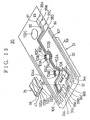
head supporting mechanism 90 according to a sixth embodiment of the present invention. Fig. 14 shows a free end of a load beam of the magnetichead supporting mechanism 90. Themechanism 90 is designed so that it does not have any influence of the stiffness of lead wires, which affect flying of the slider having a low airbearing stiffness. For example, when, in the case where four lead wires are connected between the slider and the load beam (see Fig. 6), each of the lead wires has a diameter of 30 µm and has an additional length (free length) of 1 mm, the rotation stiffness of the gimbal is approximately five times that of the gimbal in which there is no lead wire. This degrades the flying stability of the slider. - The magnetic
head supporting mechanism 90 haswiring patterns load beam 21 in the longitudinal direction. Each of the wiring patterns 91 - 94 is approximately 5 µm thick and 50 µm wide. The thickness and width of the wiring patterns depend on the resistance of the conductive pattern and the capacity of theload beam 21.Terminals 95A - 95D made of copper are formed on the base portion of theload beam 21. Further,terminals 96A - 96D are formed in aterminal area 30a of the magnetic headslider fixing portion 30 of thegimbal 25. The tops of theterminals 95A - 95D and 96A - 96D are plated by, for example, Au. This plating contributes to preventing exposure of copper and improving the bonding performance. Ends of thewiring patterns terminals wiring patterns beams terminals wiring patterns beams terminals - As shown in Fig. 15, the
wiring patterns load beam 21 by means of an insulatingfilm 97, and are covered by aprotection film 98. The insulatingfilm 97 and theprotection film 98 are made of photosensitive polyimide and are grown to a thickness of approximately 5 µm. The insulatingfilm 97 and theprotection film 98 are respectively patterned by the photolithography technique. The thickness of the insulatingfilm 97 is determined on the basis of a capacitance between the conductive pattern (made of Cu) and the load beam (made of stainless steel). - As will be described later, polyimide has heat-resistance enough for an annealing process. Since polyimide has photosensitivity, it can be easily patterned. Further, the
polyimide films - It is likely that the
terminals 95A - 95D and 96A - 96D are etched because these terminals are not covered by theprotection film 98. In order to prevent theterminals 95A - 95D and 96A - 96D from being etched, the surfaces of these terminals are covered by an Au film (not shown) having a thickness of approximately 1 µm formed by plating or vapor deposition. - As shown in Fig. 16, the
magnetic head slider 35 is made to adhere to the fixingportion 30 by means of an adhesive. Theterminals 96A - 96D are located at a right angle with respect toterminals 100A - 100D of themagnetic head 48 formed on the end surface of themagnetic head slider 35, and are respectively connected to theterminals 100A - 100D by means ofAu balls 101A - 101D. TheAu balls 101A - 101D are formed by means of, for example, a gold ball bonder device. In order to facilitate bonding, theterminals 96A - 96D andterminals 100A - 100D are located as shown in Fig. 16. In order to facilitate a crimp operation on theAu balls 101A - 101D, theterminals 100A - 100D are long in the direction of the height of themagnetic head slider 35 and are located so that theseterminals 100A - 100D face theterminals 96A - 96D in the state where thehead slider 35 is fixed to the fixingportion 30. - The wiring patterns 91 - 94
bypass holes head slider 35. Thehole 102C is used to fix theload beam 21 to the arm 22 (not shown in Fig. 13). Theholes - As shown in Figs. 13 and 14, dummy patterns 103A - 103D and 104A - 104D are provided so that these dummy patterns are symmetrical to the bypassing portions of the wiring patterns 91 - 94 with respect to the
holes film 97 and theprotection film 98 are provided for the dummy patterns 103A - 103D and 104A - 104D in the same manner as the wiring patterns 91 - 94. The dummy patterns 103A - 103D and 104A - 104D are provided in order to balance the mechanical stiffness of theload beam 21 in the direction of the width of theload beam 21. - As shown in Fig. 14, the wiring patterns 91 - 94 are arranged so that these patterns form a loop. This loop functions as an antenna, which receives noise components contained in the head signals. As the size of the loop is increased, the degree of the noise components is increased. In order to reduce the loop, the
wiring patterns terminals hole 102A and themagnetic head slider 35, and all the wiring patterns 91 - 94 are gathered in the vicinity of thehole 102A. In order to balance the stiffness in the direction of the width of the load beam, thedummy patterns 104A - 104D are formed. For the same reason as above, the dummy patterns 103A - 103D are formed in the vicinity of thehole 102B. - As shown in Fig. 14,
auxiliary films load beam 21. Theauxiliary films load beam 21 is clamped in a bending process which will be described later. Such a clamping force is also received by the wiring patterns 91 - 94. The clamping force is distributed so that the clamping force is exerted on not only the wiring patterns 91 - 94 but also theauxiliary films - As shown in Figs. 13 and 14, a
convex dummy pattern 108 is provided in order to prevent an adhesive from flowing from the fixingportion 30 when theslider 35 is fixed to the fixingportion 30 and to prevent theslider 35 from being tilted due to the thickness of the wiring patterns. More particularly, theconvex pattern 108 is used to form a groove in which adhesive used to fix theslider 35 is saved between thepattern 108 and theterminals 96A - 96D. Further, theconvex pattern 108 is designed to have the same height as the patterns having theterminals 96A - 96D. If thedummy pattern 108 is not used, theslider 35 will be inclined with respect to the fixingportion 30 due to the height of theterminals 94A - 94D. This degrades the flying stability of the heads. Theconvex pattern 108 can be formed by a cooper-plated thin film similar to the wiring patterns 91 - 94. Theprotection film 98 covers theconvex pattern 108. The adhesive is provided on a step part between the wiring patterns and theconvex pattern 108. - The
load beam 21 is produced by a process shown in Fig. 17. First, apattern formation step 110 is performed. More particularly, photosensitive polyimide is coated on a stainless plate. The insulatingfilm 97 is formed by the photolithography technique. A copper film is formed by the plating process, the vapor deposition process or the like, and is patterned into the wiring patterns 91 - 94 by the photolithography technique. Thereafter, photosensitive polyimide is coated and is patterned into theprotection film 98 and theauxiliary films - Next, an
etching step 111 is performed in order to form the openings 26 - 29 and theholes 102A - 102C and the outward form of the load beam in the stainless plate. Fig. 18 shows loadbeams 202 before punching for cutting off bridge portions (not shown) to provide pieces, so that the load beams 202 are formed in astainless plate 201 and arranged in rows and columns. - Then, a bending
step 112 is performed by bending the respective ends of each of the load beams 202 formed in thestainless plate 201, so thatribs 21a are formed. The bendingstep 112 can be performed by press so that the load beams 202 are processed at the same time. - Finally, an
annealing step 113 is performed at a temperature of approximately 400 °C, so that internal stress can be removed. Further, a slider adhering step and an Au bonding step can be automatically carried out before the load beams 202 are punched. Hence, it is possible to automatically perform the production process shown in Fig. 17 and reduce the number of steps and the cost thereof. - The
load beam 21 can be produced without performing theannealing step 113. In this case, as shown in Fig. 19, thepattern formation step 110 and theetching step 111 are performed, and subsequently the slider adhering step and the Au bonding step are carried out. Thereafter, the bendingstep 112 is carried out to form theribs 21a. - As shown in Fig. 20, when interactive type heads 48A and 48B for recording and reproduction are used as magnetic heads, the
magnetic head slider 35 has the aforementioned twoterminals gimbal 25, the twowiring patterns beams dummy patterns beam load beam 21 in the direction of the width of theload beam 21. - The magnetic
head supporting mechanism 90 has the following features. - First, since the wiring patterns 91 - 94 are formed on the
load beam 21, it is not necessary to provide tubes for passing the lead wires through theload beam 21. Hence, it is possible to prevent unbalanced force caused by the lead wires and tubes from being exerted on themagnetic head slider 35 and to stably fly themagnetic head slider 35. - Second, due to use of the dummy patterns 103A - 103D and 104A - 104D, the rotation stiffness of the
load beam 21 does not have polarity. Hence, the magnetic head slider can be flied stably. - Third, the crimp connection using the
Au balls 101A - 101D enables automatic assembly and non-bire bonding between head terminals and pattern terminals. - In the aforementioned embodiments of the present invention, the beams may be curved.
- A description will now be given of a magnetic head supporting mechanism suitable for a more compact magnetic disk drive according to a seventh embodiment of the present invention.
- Fig. 21 shows a back surface of a magnetic
head supporting mechanism 230 according to the seventh embodiment of the present invention. Fig. 22 shows a 1.8-inch-typemagnetic disk drive 231 to which the magnetichead supporting mechanism 230 is applied. - The
magnetic disk drive 231 has anenclosure 232 having almost the same dimensions as those of an IC memory card. In theenclosure 232, provided are amagnetic disk 233 having a diameter of 1.8 inches, and an actuator to which two sets of magnetic head supporting mechanisms are attached. Themagnetic disk drive 231 is more compact than themagnetic disk drive 220 shown in Fig. 3. - A
magnetic head slider 35C is made compact in accordance with light-sizing of themagnetic disk drive 231. More particularly, dimensions a x b of themagnetic head slider 35C are 0.8 mm x 1.0 mm, and are approximately one-quarter the area of themagnetic head slider 35 shown in Fig. 2. In order to stably fly the compactmagnetic head slider 35C, it is necessary to considerably reduce the stiffness without decreasing the resonance frequency, as compared with the magnetichead supporting mechanism 30. - A
load beam 235 shown in Fig. 21 is made of stainless, and has a base portion fixed to anarm 236 of the actuator 234 (see Fig. 22). Theload beam 235 has a width W2 of approximately 2 mm, a length L of approximately 9 mm, and a thickness to of approximately 25 µm, and is approximately a half of the volume of theload beam 21 shown in Fig. 2. Theload beam 235 is diminished, and hence the resonance frequency of bending which will be described later is high. - The
load beam 235 is a sheet-shaped piece, and a flat plate piece to which a bending process has not been subjected. Hence, there is no problem of a bending process error which degrades the flying stability of the magnetic head slider. Theload beam 235 includes a load beammain body 237 and agimbal 238 located on the end side of theload beam 235. Thegimbal 238 has a substantially U-shaped opening (through hole) 239 formed in theload beam 235. Thegimbal 238 includes a magnetic headslider fixing portion 240, afirst beam 241, asecond beam 242, athird beam 244, and a connectingportion 243. - The magnetic head
slider fixing portion 240 has a size corresponding to themagnetic head slider 35C. Thefirst beam 241 and thesecond beam 242 extend along respective longitudinal ends of theload beam 235 from the end thereof. The connectingportion 243 extends in the direction of the width of theload beam 235, and connects thefirst beam 241 and thesecond beam 242 together. Thethird beam 244 extends from the connectingportion 243 to the magnetic headslider fixing portion 240 in the longitudinal direction of theload beam 235. The magnetic headslider fixing portion 240 is connected to themain body 237 of theload beam 235 via thethird beam 244, the connectingportion 243 and the first andsecond beams load beam 230 can be reduced to a small value due to bending of the whole beams. - As shown in Fig. 21, holes 245, 246 and 247 with which a tool is engaged, and a pair of
slits main body 237 of theload beam 235. Adjustment slits 248 and 249 are used to reduce the rotation stiffness of the load beam. Theholes slits connectors 95A - 95D, 96A - 96D and the wiring patterns 91 - 94 are formed symmetrically with respect to the longitudinal direction of theload beam 235. Themagnetic head slider 35C is made to adhere to the fixingportion 240, and theterminals 96A - 96D and 100A - 100D are respectively connected to each other by means of Au balls as in the case shown in Fig. 16. - The structure shown in Fig. 21 does not use dummy patterns because the length and the width of the
load beam 235 are less than those of the load beam shown in Fig. 13 and the loop formed by the wiring patterns is smaller than that shown in Fig. 13. However, it is preferable to arrange the wiring patterns and provide the dummy patterns as shown in Figs. 13 and 14 in order to reduce the noise from the heads. - As shown in Figs. 23A and 23B, the free end of the
arm 236 is bent so that a substantially V-shaped cross section of thearm 236 is formed in which the "V" is inverted. The free end of thearm 236 has anupward slant portion 236a and adownward slant portion 236b declined at an angle θ with respect to the horizontal direction. - The
magnetic disk drive 231 uses two magnetichead supporting mechanisms 230 so that the singlemagnetic disk 233 is sandwiched between themechanisms 230. As shown in Fig. 24, theload beam 235 causes themagnetic head slider 35C to come into contact with themagnetic disk 233 when themagnetic disk 233 is not being rotated. At this time, themain body 237 of theload beam 235 is caused to be bent and elastically deformed. The elastic force stored in themain body 237 of theload beam 235 generates a load Fl, which urges themagnetic head slider 35C towards themagnetic disk 233. - Since the
arm 236 is bent in the form of the inverted "V", awide gap 250 can be formed between anend 236c of thearm 236 and themagnetic disk 233, as compared with a case indicated by a two-dot chained line in which thearm 236 is simply bent downwards. - A description will now be given of a moment exerted on the
magnetic head slider 35C by means of theload beam 235 when the load beam is loaded on the disk. As shown in Fig. 25, themain body 237 of theload beam 235 and thethird beam 244 are bent. Hence, a moment is exerted by acenter 251 of themagnetic head slider 35C. A moment M1 directed counterclockwise is exerted by the load beammain body 237 and the first andsecond beams third beam 244. The dimensions of theload beam 235 are selected so that the moments M1 and M2 are balanced. For example, theload beam 235 is 9 mm long, and thegimbal 238 is 2.5 mm long. Further, the length and width of themain body 235 of theload beam 237 are 5.7 mm and 2 mm, respectively. With the above structure, it is possible to stably fly themagnetic head slider 35C. - A description will now be given, with reference to Fig. 21, of pitching and rolling of the
magnetic head slider 35C. - The
magnetic head slider 35C is rotated in the pitching direction indicated byarrow 44 in such a manner that the first, second andthird beams main body 237 are bent. At this time, all thebeams gimbal 238 is bent and hence the load beammain body 237 is bent. Hence, the pitch stiffness can be greatly reduced. - The
magnetic head slider 35C is rotated in the rolling direction indicated byarrow 45 in such a manner that the first andsecond beams main body 237 is twisted. At this time, thegimbal 238 is bent and hence the load beammain body 237 is bent. Hence, the rolling stiffness can be greatly reduced. - A description will now be given of the first-order bend and the first-order twist of the magnetic
head supporting mechanism 230 obtained when the load beam is vibrated. - The
load beam 235 is bent and deformed, as shown in Fig. 26. More specifically, the load beammain body 237, and the first, second andthird beams gimbal 238 are bent as shown in Fig. 24. Theoverall load beam 235 is formed flexibly, but the resonance frequency of the first-order bend is high, while the stiffness is small. - The
load beam 235 is twisted as shown in Fig. 27. Thegimbal 238 is deformed and hence the load beammain body 237 is deformed. Hence, theoverall load beam 235 is flexibly formed, but the resonance frequency of the first-order twist is high while the stiffness thereof is low. - Tables 3 and 4 show characteristics of the magnetic
head support mechanism 230 according to the seventh embodiment of the present invention and the magnetichead supporting mechanism 30 of the first embodiment thereof shown in Fig. 2.Table 3 COMPARISON OF STIFFNESS (static characteristics by computer simulation) Stiffness 7th embodiment 1st embodiment pitch stiffness 0.44 grf cm/rad 1.5 grf cm/rad roll stiffness 0.24 grf cm/rad 1.5 grf cm/rad up/down stiffness 0.36 grf/mm 0.55 grf/mm equivalent weight ratio 0.76 0.74 Table 4 COMPARISON OF RESONANCE FREQUENCY (dynamic characteristic by computer simulation) Stiffness 7th embodiment 1st embodiment 1st bend 1.6 kHz 2.1 kHz 1st twist 4.4 kHz 2.3 kHz in-plane 7.1 kHz 8.5 kHz - More particularly, Table 3 the pitch stiffness, the roll stiffness, and the up/down stiffness of the
load beam 235 obtained by means of a computer simulation. It can be from Table 3 that the pitch stiffness and the roll stiffness of the seventh embodiment of the present invention are approximately one-quarter of those of the first embodiment thereof. - Table 4 shows the resonance frequencies of the first and seventh embodiments of the present invention obtained by a computer simulation. It can be seen from Table 4 that the first-order bend resonance frequency, the first-order twist resonance frequency and the lateral resonance frequency are kept very high.
- It can be seen from Tables 3 and 4 that the magnetic
head supporting mechanism 230 according to the seventh embodiment of the present invention has a resonance frequency as high as that of the magnetichead supporting mechanism 30 according to the first embodiment, and stiffness much less than that of themechanism 30. Hence, the compactmagnetic head slider 35C can be stably flied. - In an alternative of the load beam, the base portion of the
load beam 237 is bent, so that the load beam is supported in the same manner as shown in Fig. 2 and the load Fl shown in Fig. 24 is obtained. In this case, onlyportions slits slits - A first variation of the
gimbal 238 of theload beam 235 will be described. Agimbal 238-1 shown in Fig. 28 has afirst beam 244-1 having a long width A, and anopening 239-1 having a long length B. First andsecond beams - Fig. 29 shows a
second variation 238-2 of thegimbal 238. Thegimbal 238-2 has first andsecond beams - Fig. 30 shows a
third variation 238-3 of thegimbal 238. Thegimbal 238-3 has first andsecond variations - Fig. 31 shows a
fourth variation 238-4 of thegimbal 238. Thegimbal 238-4 has afourth beam 260 connecting the center of the end of the magnetic headslider fixing portion 240 and the load beammain body 237 together. Thefourth beam 260 functions to prevent a deformation of the magnetic headslider fixing portion 240, but increases the rotation stiffness. Hence, it is desired that the width of thefourth beam 260 be as small as possible and the length thereof are as long as possible. - Fig. 32 shows a
fifth variation 238-5 of thegimbal 238. Thegimbal 238-5 has first and second arch-shapedbeams - As shown in Fig. 33, a bent connecting
plate 261 is fixed to anarm 236A, and theload beam 235 is fixed to the connectingplate 261. Hence, it is not necessary to subject thearm 236A to the bending process. - In the variations shown in Fig. 28 through 32, it can be said that the
third beam 244 shown in Fig. 21 has the same width as the fixingportion 240 and is integrated with the fixingportion 240. - In the first through sixth embodiments, the load applied to the magnetic head slider is generated by bending the spring portion of the load beam. Alternatively, it is possible to employ the arm fixing structure used in the seventh embodiment of the present invention in which the spring portion is kept flat.
- The present invention is not limited to the specifically disclosed embodiments and variations, and other variations and modifications may be made without departing from the scope of the present invention.
Claims (1)
- A sheet-like head slider supporting assembly adapted to support a head slider at an end of the head slider supporting assembly, said head slider supporting assembly comprising:a base portion (21);a head slider fixing portion (30) disposed on a front side of the base portion and adapted to fix the head slider (35);a beam portion (31, 32) connecting the head slider fixing portion and the base portion,wherein the head-slider fixing portion comprises terminals (96A-96D) at a front end of the head slider fixing portion and a convex pattern (108) at a rear end of the head slider fixing portion.
Applications Claiming Priority (4)
| Application Number | Priority Date | Filing Date | Title |
|---|---|---|---|
| JP31884692 | 1992-11-27 | ||
| JP08211093A JP3667354B2 (en) | 1992-11-27 | 1993-04-08 | Head slider support |
| EP01124285A EP1174860B1 (en) | 1992-11-27 | 1993-08-26 | Magnetic head supporting mechanism |
| EP93402099A EP0599669B1 (en) | 1992-11-27 | 1993-08-26 | Magnetic head supporting mechanism |
Related Parent Applications (1)
| Application Number | Title | Priority Date | Filing Date |
|---|---|---|---|
| EP01124285A Division EP1174860B1 (en) | 1992-11-27 | 1993-08-26 | Magnetic head supporting mechanism |
Publications (2)
| Publication Number | Publication Date |
|---|---|
| EP1638087A1 true EP1638087A1 (en) | 2006-03-22 |
| EP1638087B1 EP1638087B1 (en) | 2009-03-11 |
Family
ID=26423129
Family Applications (5)
| Application Number | Title | Priority Date | Filing Date |
|---|---|---|---|
| EP01124285A Expired - Lifetime EP1174860B1 (en) | 1992-11-27 | 1993-08-26 | Magnetic head supporting mechanism |
| EP04021390A Withdrawn EP1484750A1 (en) | 1992-11-27 | 1993-08-26 | Magnetic head supporting mechanism |
| EP96103694A Expired - Lifetime EP0716413B1 (en) | 1992-11-27 | 1993-08-26 | Magnetic head supporting mechanism and wiring structure therefor |
| EP93402099A Expired - Lifetime EP0599669B1 (en) | 1992-11-27 | 1993-08-26 | Magnetic head supporting mechanism |
| EP05028460A Expired - Lifetime EP1638087B1 (en) | 1992-11-27 | 1993-08-26 | Magnetic head supporting mechanism |
Family Applications Before (4)
| Application Number | Title | Priority Date | Filing Date |
|---|---|---|---|
| EP01124285A Expired - Lifetime EP1174860B1 (en) | 1992-11-27 | 1993-08-26 | Magnetic head supporting mechanism |
| EP04021390A Withdrawn EP1484750A1 (en) | 1992-11-27 | 1993-08-26 | Magnetic head supporting mechanism |
| EP96103694A Expired - Lifetime EP0716413B1 (en) | 1992-11-27 | 1993-08-26 | Magnetic head supporting mechanism and wiring structure therefor |
| EP93402099A Expired - Lifetime EP0599669B1 (en) | 1992-11-27 | 1993-08-26 | Magnetic head supporting mechanism |
Country Status (4)
| Country | Link |
|---|---|
| US (4) | US6522505B1 (en) |
| EP (5) | EP1174860B1 (en) |
| JP (1) | JP3667354B2 (en) |
| DE (4) | DE69333994T2 (en) |
Families Citing this family (40)
| Publication number | Priority date | Publication date | Assignee | Title |
|---|---|---|---|---|
| JP3262445B2 (en) * | 1994-02-18 | 2002-03-04 | 富士通株式会社 | Head assembly and storage device |
| US5781379A (en) * | 1994-03-15 | 1998-07-14 | International Business Machines Corporation | Single beam flexure for a head gimbal assembly |
| US6351348B1 (en) | 1994-03-15 | 2002-02-26 | International Business Machines Corporation | Minimal stiffness conductors for a head gimbal assembly |
| US6282064B1 (en) | 1994-03-15 | 2001-08-28 | International Business Machines Corporation | Head gimbal assembly with integrated electrical conductors |
| US5839193A (en) * | 1994-04-15 | 1998-11-24 | Hutchinson Technology Incorporated | Method of making laminated structures for a disk drive suspension assembly |
| US5491597A (en) * | 1994-04-15 | 1996-02-13 | Hutchinson Technology Incorporated | Gimbal flexure and electrical interconnect assembly |
| US5598307A (en) * | 1994-04-15 | 1997-01-28 | Hutchinson Technology Inc. | Integrated gimbal suspension assembly |
| JP2955829B2 (en) | 1994-04-15 | 1999-10-04 | ハッチンソン テクノロジー インコーポレイテッド | Head suspension |
| US6539609B2 (en) | 1994-07-05 | 2003-04-01 | International Business Machines Corporation | Method of forming a head gimbal assembly |
| JPH08111015A (en) * | 1994-09-01 | 1996-04-30 | Tdk Corp | Supporting device of magnetic head slider and magnetic head device |
| JP3252620B2 (en) * | 1994-10-20 | 2002-02-04 | 株式会社日立製作所 | Magnetic head support mechanism and magnetic disk drive |
| JP3423793B2 (en) * | 1994-11-17 | 2003-07-07 | 富士通株式会社 | Method and apparatus for manufacturing magnetic head arm |
| JP3173714B2 (en) * | 1994-12-08 | 2001-06-04 | インターナショナル・ビジネス・マシーンズ・コーポレ−ション | Suspension system |
| US5835306A (en) * | 1995-06-07 | 1998-11-10 | Hutchinson Technology Incorporated | Integrated gimbal suspension assembly with assymetric bond pad |
| US5808834A (en) * | 1995-06-07 | 1998-09-15 | Hutchinson Technology Incorporated | Laminated adapter |
| JP3296187B2 (en) * | 1996-04-15 | 2002-06-24 | ティーディーケイ株式会社 | Magnetic head slider support mechanism and head gimbal assembly using the support mechanism |
| US5956209A (en) * | 1996-10-04 | 1999-09-21 | International Business Machines Corporation | Integrated suspension flexure having a compliant tip termination platform |
| US5912787A (en) * | 1996-10-07 | 1999-06-15 | Magnecomp Corp. | Disk drive suspension with minimum wire-induced bias |
| JPH10162518A (en) * | 1996-11-28 | 1998-06-19 | Hitachi Ltd | Suspension for magnetic head and magnetic storage device utilizing the same |
| JP3756650B2 (en) | 1996-12-19 | 2006-03-15 | ハッチンソン テクノロジー インコーポレーティッド | Integrated lead suspension flexure with balanced parallel leads for insulator layer temperature and humidity compensation |
| US5982584A (en) * | 1996-12-19 | 1999-11-09 | Hutchinson Technology Incorporated | Integrated lead suspension flexure with serially arranged metal-backed and suspended insulator portions for hygrothermal compensation |
| US6147839A (en) * | 1996-12-23 | 2000-11-14 | Hutchinson Technology, Inc. | Head suspension with outriggers extending across a spring region |
| JP3340352B2 (en) * | 1997-05-22 | 2002-11-05 | 富士通株式会社 | Method of manufacturing suspension element for magnetic head having wiring pattern |
| JP2995164B2 (en) | 1997-07-23 | 1999-12-27 | サンコール株式会社 | Magnetic head slider support mechanism and method of manufacturing the same |
| US6437944B2 (en) | 1997-10-20 | 2002-08-20 | Fujitsu Limited | Head slider supporting device, disk device and suspension |
| JPH11149625A (en) * | 1997-11-19 | 1999-06-02 | Fujitsu Ltd | Suspension for head assembly, and method of manufacturing head assembly and suspension for head assembly |
| US6612016B1 (en) | 1997-12-18 | 2003-09-02 | Hutchinson Technology Incorporated | Method of making integrated lead suspension flexure with balanced parallel leads for insulator layer hygrothermal compensation |
| JP2001043647A (en) * | 1999-07-15 | 2001-02-16 | Internatl Business Mach Corp <Ibm> | Hard disk drive, slider holding structure, head gimbals assembly and its manufacture |
| JP3988420B2 (en) | 2001-09-19 | 2007-10-10 | Tdk株式会社 | Thin film magnetic head wiring member, head gimbal assembly, head gimbal assembly inspection method, and head gimbal assembly manufacturing method |
| US7304824B2 (en) * | 2002-09-10 | 2007-12-04 | Intri-Plex Technologies, Inc. | Plated base plate for suspension assembly in disk drive |
| US7203033B2 (en) * | 2002-10-02 | 2007-04-10 | Seagate Technology Llc | Head gimbal assembly with an integrated mechanical and electrical attachment and a stiff plate |
| US7042670B2 (en) * | 2003-07-11 | 2006-05-09 | Sae Magnetics (H.K.) Ltd. | Method for adjusting flying height of magnetic heads using an electrical charge through an electrical pad on the slider |
| US7057856B2 (en) * | 2003-11-06 | 2006-06-06 | Seagate Technology Llc | Gimbal strut shape to increase buckling load |
| JP2005149651A (en) | 2003-11-18 | 2005-06-09 | Shinka Jitsugyo Kk | Magnetic disk drive |
| JP4352870B2 (en) | 2003-11-20 | 2009-10-28 | 新科實業有限公司 | Magnetic disk drive device |
| JP4158691B2 (en) | 2003-12-01 | 2008-10-01 | 新科實業有限公司 | Magnetic disk drive device and method of manufacturing magnetic disk drive device |
| JP2006244544A (en) | 2005-03-01 | 2006-09-14 | Shinka Jitsugyo Kk | Magnetic disk drive device and its manufacturing method |
| US7433156B2 (en) * | 2006-02-10 | 2008-10-07 | Sae Magnetics (Hk) Ltd. | Flexure for minimizing fly height modulation of near-contact recording sliders in a disk drive |
| US8054585B2 (en) * | 2006-11-28 | 2011-11-08 | Sae Magnetics (Hk) Ltd. | Gimbal with assymmetric dynamic stiffness |
| WO2009003318A1 (en) * | 2007-07-05 | 2009-01-08 | Sae Magnetics (H.K.) Ltd. | Suspension design for high shock performance soldering ball bonding |
Citations (4)
| Publication number | Priority date | Publication date | Assignee | Title |
|---|---|---|---|---|
| JPS6383908A (en) * | 1986-09-29 | 1988-04-14 | Toshiba Corp | Magnetic head device |
| EP0265720A2 (en) * | 1986-10-28 | 1988-05-04 | International Business Machines Corporation | A slider-suspension assembly and method for attaching a slider to a suspension in a data recording disk file |
| EP0389020A1 (en) * | 1989-03-13 | 1990-09-26 | Koninklijke Philips Electronics N.V. | Surface-mounted multilayer capacitor and printed circuit board having such a multilayer capacitor |
| US5166846A (en) * | 1989-05-25 | 1992-11-24 | Sony Corporation | Magnetic head with shielded mounting |
Family Cites Families (68)
| Publication number | Priority date | Publication date | Assignee | Title |
|---|---|---|---|---|
| US3702461A (en) * | 1971-05-19 | 1972-11-07 | Century Data Systems Inc | Disk file gimbal head mount |
| JPS5330310A (en) * | 1976-09-01 | 1978-03-22 | Fujitsu Ltd | Magnetic head assembly of floating type |
| JPS5374414A (en) * | 1976-12-15 | 1978-07-01 | Matsushita Electric Ind Co Ltd | Thin film flying head |
| JPS5454614A (en) * | 1977-10-07 | 1979-05-01 | Nec Corp | Floating type magnetic head assembly |
| JPS5583243A (en) | 1978-12-19 | 1980-06-23 | Mitsubishi Electric Corp | Wire bonding apparatus |
| JPS5588345A (en) | 1978-12-27 | 1980-07-04 | Hitachi Ltd | Wire bonding method and capillary used therefor |
| EP0075413A3 (en) * | 1981-09-12 | 1983-07-27 | Chubb Integrated Systems Limited | Magnetoresistive transducer assemblies |
| JPS58138043A (en) | 1982-02-12 | 1983-08-16 | Citizen Watch Co Ltd | Ic bonding method |
| JPS5960761A (en) | 1982-09-30 | 1984-04-06 | Toshiba Corp | Magnetic head supporting device |
| JPS5979463A (en) * | 1982-10-29 | 1984-05-08 | Toshiba Corp | Magnetic head device |
| JPS60136911A (en) | 1983-12-26 | 1985-07-20 | Hitachi Ltd | Magnetic head support device |
| JPS60246015A (en) * | 1984-05-21 | 1985-12-05 | Nippon Telegr & Teleph Corp <Ntt> | Gimbal spring for magnetic head |
| JPS61104315A (en) * | 1984-10-22 | 1986-05-22 | Fujitsu Ltd | Magnetic head assembly |
| JPS626473A (en) | 1985-06-29 | 1987-01-13 | Sony Corp | Head supporting device |
| US4670804A (en) * | 1985-10-15 | 1987-06-02 | International Business Machines Corporation | Expandable suspension for a read/write head in a disk file |
| US4717066A (en) * | 1986-02-24 | 1988-01-05 | American Telephone And Telegraph Company, At&T Bell Laboratories | Method of bonding conductors to semiconductor devices |
| JPS63239649A (en) | 1986-11-12 | 1988-10-05 | Seiko Epson Corp | Magnetic head supporting mechanism |
| DE3788930T2 (en) * | 1986-11-12 | 1994-08-18 | Seiko Epson Corp | Assembly of magnetic heads. |
| JPS63313376A (en) * | 1987-06-16 | 1988-12-21 | Canon Electronics Inc | Magnetic head |
| JP2514976B2 (en) | 1987-07-22 | 1996-07-10 | 日立金属株式会社 | Floating magnetic head device |
| JPS6478313A (en) | 1987-09-19 | 1989-03-23 | Takamisawa Cybernetics | Interface for no-break power unit |
| JPH01128277A (en) | 1987-11-12 | 1989-05-19 | Nec Corp | Magnetic head |
| US4884155A (en) * | 1987-12-04 | 1989-11-28 | Digital Equipment Corporation | Self-loading head assembly for disk drives |
| US5185683A (en) * | 1987-12-21 | 1993-02-09 | Hutchinson Technology, Inc. | Suspension arm mounting assembly |
| JPH083888B2 (en) | 1987-12-23 | 1996-01-17 | 株式会社日立製作所 | Magnetic head |
| JPH01235315A (en) | 1988-03-16 | 1989-09-20 | Hitachi Ltd | Method of controlling superconducting coil |
| US5012369A (en) * | 1988-05-18 | 1991-04-30 | Fujitsu Limited | Head suspension mechanism of a recording apparatus with a constant flying height |
| JPH0215412A (en) * | 1988-07-04 | 1990-01-19 | Matsushita Electric Ind Co Ltd | Magnetic head |
| JPH0230170A (en) | 1988-07-19 | 1990-01-31 | Matsushita Electric Works Ltd | Semiconductor package and manufacture thereof |
| JPH06101213B2 (en) * | 1988-07-25 | 1994-12-12 | 日本電気株式会社 | Supporting device for magnetic head slider |
| JPH0782630B2 (en) | 1989-02-28 | 1995-09-06 | 三菱電機株式会社 | Thin film magnetic head device |
| US5006946A (en) * | 1989-04-19 | 1991-04-09 | Tdk Corporation | Flexible polymeric resinous magnetic head supporting device |
| EP0397896B1 (en) * | 1989-05-13 | 1994-11-30 | Ibm Deutschland Gmbh | Low profil magnetic head suspension |
| JP3117203B2 (en) | 1989-08-31 | 2000-12-11 | 株式会社東芝 | Light emitting diode and method of manufacturing the same |
| US4996623A (en) | 1989-08-07 | 1991-02-26 | International Business Machines Corporation | Laminated suspension for a negative pressure slider in a data recording disk file |
| JPH03189976A (en) | 1989-12-19 | 1991-08-19 | Matsushita Electric Ind Co Ltd | Magnetic head support device |
| JPH03209610A (en) * | 1990-01-11 | 1991-09-12 | Matsushita Electric Ind Co Ltd | Production of thin-film magnetic head |
| JPH03238616A (en) | 1990-02-16 | 1991-10-24 | Mitsubishi Electric Corp | Magnetic head supporting mechanism |
| JPH0421918A (en) | 1990-05-17 | 1992-01-24 | Fujitsu Ltd | Magnetic head |
| JPH0440680A (en) | 1990-06-05 | 1992-02-12 | Fujitsu Ltd | Supporting mechanism for floating type magnetic head |
| JP2771690B2 (en) | 1990-10-25 | 1998-07-02 | アルプス電気株式会社 | Floating magnetic head support device |
| EP0484906A3 (en) | 1990-11-09 | 1993-04-28 | Brier Technology | Head mounting device |
| US5198945A (en) | 1990-11-09 | 1993-03-30 | Hutchinson Technology Incorporated | Magnetic head suspension |
| BR9104482A (en) * | 1990-11-29 | 1992-06-23 | Hewlett Packard Co | LOADING ARM FOR DISC DRIVING MECHANISM |
| JPH04219618A (en) | 1990-12-19 | 1992-08-10 | Fujitsu Ltd | Manufacture of magnetic head supporting structure |
| JP3256983B2 (en) | 1991-04-19 | 2002-02-18 | トキコ株式会社 | Magnetic disk drive and support spring |
| US5291359A (en) * | 1991-04-29 | 1994-03-01 | Hutchinson Technology Incorporated | Head suspension assembly including a flexure having rails arranged for interfacing with a head ramp |
| JPH0755687Y2 (en) * | 1991-05-08 | 1995-12-20 | ティアック株式会社 | Magnetic head device for magnetic disk |
| JP3189976B2 (en) | 1991-05-31 | 2001-07-16 | キヤノン株式会社 | Laser diode driving method, laser diode driving circuit, and optical transmission system using the same |
| JPH0574086A (en) | 1991-09-12 | 1993-03-26 | Internatl Business Mach Corp <Ibm> | Structure and method for attaching suspension of disk memory device |
| JPH05166159A (en) | 1991-12-16 | 1993-07-02 | Sony Corp | Production of magnetic head assembly |
| DE69333464T2 (en) * | 1992-01-20 | 2004-09-09 | Fujitsu Ltd., Kawasaki | MAGNETIC HEAD ARRANGEMENT, THEIR PRODUCTION AND MAGNETIC DISK DEVICE |
| US5305168A (en) | 1992-03-05 | 1994-04-19 | Magnex Corporation | Thin film transducer suspension assembly with flexuro mounted booster element |
| JPH05282642A (en) | 1992-04-02 | 1993-10-29 | Sony Corp | Magnetic disk device |
| JPH0755688Y2 (en) | 1992-06-12 | 1995-12-20 | ティアック株式会社 | Flexible printed circuit board for head |
| US5381288A (en) | 1992-06-16 | 1995-01-10 | Applied Magnetics Corporation, Inc. | Center moment suspension assembly |
| US6341415B2 (en) * | 1992-08-31 | 2002-01-29 | Fujitsu Limited | Method for assembling a magnetic head assembly and magnetic disk drive using bonding balls connecting magnetic head terminals to wiring terminals |
| JPH06124558A (en) | 1992-10-12 | 1994-05-06 | Hitachi Ltd | Magnetic head suspension |
| US5331489A (en) | 1992-11-12 | 1994-07-19 | Seagate Technology, Inc. | Gimbal for a flexure for top-terminated heads |
| JPH06203354A (en) | 1992-11-13 | 1994-07-22 | Sony Corp | Head supporting mechanism |
| US6002548A (en) * | 1992-11-27 | 1999-12-14 | Fujitsu Limited | Magnetic head supporting mechanism |
| JP3209610B2 (en) | 1993-03-31 | 2001-09-17 | 東京製綱株式会社 | Non-rotating wire rope |
| US5901014A (en) * | 1993-08-10 | 1999-05-04 | Fujitsu Limited | Thin film magnetic head and assembly configured to reduce risk of discharge between the coil and the core slider |
| US5422764A (en) | 1993-10-15 | 1995-06-06 | Hewlett-Packard Company | Electrical interconnect for a head/arm assembly of computer disk drives |
| KR960006081A (en) * | 1994-07-13 | 1996-02-23 | 가나이 쓰토무 | Semiconductor devices |
| JP3238616B2 (en) | 1995-09-29 | 2001-12-17 | 松下電器産業株式会社 | Semiconductor switch circuit |
| JP2000268513A (en) * | 1999-03-17 | 2000-09-29 | Tdk Corp | Head slider supporting body and head device and their production, as well as information recording and reproducing device |
| JP2002157725A (en) * | 2000-11-15 | 2002-05-31 | Dainippon Printing Co Ltd | Method for manufacturing wireless suspension blank |
-
1993
- 1993-04-08 JP JP08211093A patent/JP3667354B2/en not_active Expired - Lifetime
- 1993-08-26 EP EP01124285A patent/EP1174860B1/en not_active Expired - Lifetime
- 1993-08-26 DE DE69333994T patent/DE69333994T2/en not_active Expired - Fee Related
- 1993-08-26 DE DE69331966T patent/DE69331966T2/en not_active Expired - Fee Related
- 1993-08-26 EP EP04021390A patent/EP1484750A1/en not_active Withdrawn
- 1993-08-26 DE DE69334269T patent/DE69334269D1/en not_active Expired - Lifetime
- 1993-08-26 EP EP96103694A patent/EP0716413B1/en not_active Expired - Lifetime
- 1993-08-26 EP EP93402099A patent/EP0599669B1/en not_active Expired - Lifetime
- 1993-08-26 EP EP05028460A patent/EP1638087B1/en not_active Expired - Lifetime
- 1993-08-26 DE DE69325039T patent/DE69325039T2/en not_active Expired - Fee Related
-
2000
- 2000-07-21 US US09/621,331 patent/US6522505B1/en not_active Expired - Fee Related
- 2000-08-04 US US09/633,137 patent/US6560073B1/en not_active Expired - Fee Related
-
2003
- 2003-01-21 US US10/347,290 patent/US20030107845A1/en not_active Abandoned
-
2004
- 2004-10-26 US US10/972,367 patent/US7221541B2/en not_active Expired - Fee Related
Patent Citations (4)
| Publication number | Priority date | Publication date | Assignee | Title |
|---|---|---|---|---|
| JPS6383908A (en) * | 1986-09-29 | 1988-04-14 | Toshiba Corp | Magnetic head device |
| EP0265720A2 (en) * | 1986-10-28 | 1988-05-04 | International Business Machines Corporation | A slider-suspension assembly and method for attaching a slider to a suspension in a data recording disk file |
| EP0389020A1 (en) * | 1989-03-13 | 1990-09-26 | Koninklijke Philips Electronics N.V. | Surface-mounted multilayer capacitor and printed circuit board having such a multilayer capacitor |
| US5166846A (en) * | 1989-05-25 | 1992-11-24 | Sony Corporation | Magnetic head with shielded mounting |
Non-Patent Citations (1)
| Title |
|---|
| PATENT ABSTRACTS OF JAPAN vol. 012, no. 319 (P - 751) 30 August 1988 (1988-08-30) * |
Also Published As
| Publication number | Publication date |
|---|---|
| EP1484750A1 (en) | 2004-12-08 |
| EP1174860A3 (en) | 2002-04-03 |
| EP0599669B1 (en) | 2002-05-29 |
| EP0599669A2 (en) | 1994-06-01 |
| EP0716413A3 (en) | 1996-07-17 |
| DE69333994D1 (en) | 2006-05-11 |
| DE69325039D1 (en) | 1999-06-24 |
| JP3667354B2 (en) | 2005-07-06 |
| EP0716413B1 (en) | 1999-05-19 |
| US6522505B1 (en) | 2003-02-18 |
| US7221541B2 (en) | 2007-05-22 |
| EP1174860B1 (en) | 2006-03-22 |
| US20030107845A1 (en) | 2003-06-12 |
| JPH06215513A (en) | 1994-08-05 |
| EP0599669A3 (en) | 1994-06-15 |
| DE69331966T2 (en) | 2002-09-12 |
| DE69331966D1 (en) | 2002-07-04 |
| DE69325039T2 (en) | 1999-09-16 |
| US20050083610A1 (en) | 2005-04-21 |
| DE69334269D1 (en) | 2009-04-23 |
| EP1174860A2 (en) | 2002-01-23 |
| US6560073B1 (en) | 2003-05-06 |
| EP0716413A2 (en) | 1996-06-12 |
| DE69333994T2 (en) | 2006-08-17 |
| EP1638087B1 (en) | 2009-03-11 |
Similar Documents
| Publication | Publication Date | Title |
|---|---|---|
| EP1174860B1 (en) | Magnetic head supporting mechanism | |
| JP3282823B2 (en) | Multi-piece integrated suspension assembly, method of making the same, and magnetic storage system | |
| KR100278418B1 (en) | Integrated suspension bends with flexible tip termination platform | |
| US7414814B1 (en) | Disk drives, head stack, head gimbal and suspension assemblies having a compliant suspension tail design for solder reflow | |
| US5818662A (en) | Static attitude and stiffness control for an integrated suspension | |
| JP3057037B2 (en) | Method for performing ultrasonic bonding, method for deforming, maintaining and releasing suspension assembly | |
| US7733607B2 (en) | Suspension with strengthening plate, head gimbal assembly, and disk drive unit with the same | |
| US20040181932A1 (en) | System and method for manufacturing a hard disk drive suspension flexure and for preventing damage due to electrical arcing | |
| US20080297948A1 (en) | Suspension, head gimbal assembly and manufacturing method thereof, and disk drive unit with the same | |
| US6055133A (en) | Disk drive head support arm and arm assembly utilizing plural datum features | |
| US5901014A (en) | Thin film magnetic head and assembly configured to reduce risk of discharge between the coil and the core slider | |
| US6341415B2 (en) | Method for assembling a magnetic head assembly and magnetic disk drive using bonding balls connecting magnetic head terminals to wiring terminals | |
| US20050286176A1 (en) | Head gimbal assembly with flying height adjuster, disk drive unit and manufacturing method thereof | |
| US5956208A (en) | Magnetic head device having bent terminal lead wires for establishing an electrical connection with a magnetic head on a slider | |
| US6002548A (en) | Magnetic head supporting mechanism | |
| US5771138A (en) | Head gimbal assembly with transducer wires attached at two points to slider | |
| JP3139950B2 (en) | Wiring structure of load beam and guide arm of magnetic disk drive | |
| JP3093171B2 (en) | Head support arm and arm assembly for disk drive device | |
| JP4138713B2 (en) | Head slider support | |
| JP2006260767A (en) | Manufacturing method of head slider support | |
| JP3559000B2 (en) | Head slider assembly | |
| JP4058333B2 (en) | Method for manufacturing head slider support | |
| JP2002015535A (en) | Head slider base | |
| JP3565660B2 (en) | Suspension system having integral conductor and method of forming the suspension system |
Legal Events
| Date | Code | Title | Description |
|---|---|---|---|
| PUAI | Public reference made under article 153(3) epc to a published international application that has entered the european phase |
Free format text: ORIGINAL CODE: 0009012 |
|
| AC | Divisional application: reference to earlier application |
Ref document number: 0599669 Country of ref document: EP Kind code of ref document: P Ref document number: 1174860 Country of ref document: EP Kind code of ref document: P |
|
| AK | Designated contracting states |
Kind code of ref document: A1 Designated state(s): DE FR GB |
|
| 17P | Request for examination filed |
Effective date: 20061013 |
|
| AKX | Designation fees paid |
Designated state(s): DE FR GB |
|
| GRAP | Despatch of communication of intention to grant a patent |
Free format text: ORIGINAL CODE: EPIDOSNIGR1 |
|
| GRAS | Grant fee paid |
Free format text: ORIGINAL CODE: EPIDOSNIGR3 |
|
| GRAA | (expected) grant |
Free format text: ORIGINAL CODE: 0009210 |
|
| AC | Divisional application: reference to earlier application |
Ref document number: 0599669 Country of ref document: EP Kind code of ref document: P Ref document number: 1174860 Country of ref document: EP Kind code of ref document: P |
|
| AK | Designated contracting states |
Kind code of ref document: B1 Designated state(s): DE FR GB |
|
| REG | Reference to a national code |
Ref country code: GB Ref legal event code: FG4D |
|
| REF | Corresponds to: |
Ref document number: 69334269 Country of ref document: DE Date of ref document: 20090423 Kind code of ref document: P |
|
| PGFP | Annual fee paid to national office [announced via postgrant information from national office to epo] |
Ref country code: DE Payment date: 20090911 Year of fee payment: 17 Ref country code: GB Payment date: 20090826 Year of fee payment: 17 |
|
| REG | Reference to a national code |
Ref country code: GB Ref legal event code: 732E Free format text: REGISTERED BETWEEN 20091112 AND 20091118 |
|
| PLBE | No opposition filed within time limit |
Free format text: ORIGINAL CODE: 0009261 |
|
| STAA | Information on the status of an ep patent application or granted ep patent |
Free format text: STATUS: NO OPPOSITION FILED WITHIN TIME LIMIT |
|
| 26N | No opposition filed |
Effective date: 20091214 |
|
| REG | Reference to a national code |
Ref country code: FR Ref legal event code: ST Effective date: 20100430 |
|
| PG25 | Lapsed in a contracting state [announced via postgrant information from national office to epo] |
Ref country code: FR Free format text: LAPSE BECAUSE OF NON-PAYMENT OF DUE FEES Effective date: 20090831 |
|
| GBPC | Gb: european patent ceased through non-payment of renewal fee |
Effective date: 20100826 |
|
| REG | Reference to a national code |
Ref country code: DE Ref legal event code: R119 Ref document number: 69334269 Country of ref document: DE Effective date: 20110301 |
|
| PG25 | Lapsed in a contracting state [announced via postgrant information from national office to epo] |
Ref country code: DE Free format text: LAPSE BECAUSE OF NON-PAYMENT OF DUE FEES Effective date: 20110301 |
|
| PG25 | Lapsed in a contracting state [announced via postgrant information from national office to epo] |
Ref country code: GB Free format text: LAPSE BECAUSE OF NON-PAYMENT OF DUE FEES Effective date: 20100826 |