EP1634549A2 - System and method for spinal fusion - Google Patents
System and method for spinal fusion Download PDFInfo
- Publication number
- EP1634549A2 EP1634549A2 EP05077059A EP05077059A EP1634549A2 EP 1634549 A2 EP1634549 A2 EP 1634549A2 EP 05077059 A EP05077059 A EP 05077059A EP 05077059 A EP05077059 A EP 05077059A EP 1634549 A2 EP1634549 A2 EP 1634549A2
- Authority
- EP
- European Patent Office
- Prior art keywords
- interbody
- spinal fusion
- fusion system
- adjacent vertebrae
- sleeve
- Prior art date
- Legal status (The legal status is an assumption and is not a legal conclusion. Google has not performed a legal analysis and makes no representation as to the accuracy of the status listed.)
- Withdrawn
Links
Images


Classifications
-
- A—HUMAN NECESSITIES
- A61—MEDICAL OR VETERINARY SCIENCE; HYGIENE
- A61F—FILTERS IMPLANTABLE INTO BLOOD VESSELS; PROSTHESES; DEVICES PROVIDING PATENCY TO, OR PREVENTING COLLAPSING OF, TUBULAR STRUCTURES OF THE BODY, e.g. STENTS; ORTHOPAEDIC, NURSING OR CONTRACEPTIVE DEVICES; FOMENTATION; TREATMENT OR PROTECTION OF EYES OR EARS; BANDAGES, DRESSINGS OR ABSORBENT PADS; FIRST-AID KITS
- A61F2/00—Filters implantable into blood vessels; Prostheses, i.e. artificial substitutes or replacements for parts of the body; Appliances for connecting them with the body; Devices providing patency to, or preventing collapsing of, tubular structures of the body, e.g. stents
- A61F2/02—Prostheses implantable into the body
- A61F2/30—Joints
- A61F2/44—Joints for the spine, e.g. vertebrae, spinal discs
- A61F2/4455—Joints for the spine, e.g. vertebrae, spinal discs for the fusion of spinal bodies, e.g. intervertebral fusion of adjacent spinal bodies, e.g. fusion cages
-
- A—HUMAN NECESSITIES
- A61—MEDICAL OR VETERINARY SCIENCE; HYGIENE
- A61F—FILTERS IMPLANTABLE INTO BLOOD VESSELS; PROSTHESES; DEVICES PROVIDING PATENCY TO, OR PREVENTING COLLAPSING OF, TUBULAR STRUCTURES OF THE BODY, e.g. STENTS; ORTHOPAEDIC, NURSING OR CONTRACEPTIVE DEVICES; FOMENTATION; TREATMENT OR PROTECTION OF EYES OR EARS; BANDAGES, DRESSINGS OR ABSORBENT PADS; FIRST-AID KITS
- A61F2/00—Filters implantable into blood vessels; Prostheses, i.e. artificial substitutes or replacements for parts of the body; Appliances for connecting them with the body; Devices providing patency to, or preventing collapsing of, tubular structures of the body, e.g. stents
- A61F2/02—Prostheses implantable into the body
- A61F2/30—Joints
- A61F2/46—Special tools or methods for implanting or extracting artificial joints, accessories, bone grafts or substitutes, or particular adaptations therefor
- A61F2/4603—Special tools or methods for implanting or extracting artificial joints, accessories, bone grafts or substitutes, or particular adaptations therefor for insertion or extraction of endoprosthetic joints or of accessories thereof
- A61F2/4611—Special tools or methods for implanting or extracting artificial joints, accessories, bone grafts or substitutes, or particular adaptations therefor for insertion or extraction of endoprosthetic joints or of accessories thereof of spinal prostheses
-
- A—HUMAN NECESSITIES
- A61—MEDICAL OR VETERINARY SCIENCE; HYGIENE
- A61F—FILTERS IMPLANTABLE INTO BLOOD VESSELS; PROSTHESES; DEVICES PROVIDING PATENCY TO, OR PREVENTING COLLAPSING OF, TUBULAR STRUCTURES OF THE BODY, e.g. STENTS; ORTHOPAEDIC, NURSING OR CONTRACEPTIVE DEVICES; FOMENTATION; TREATMENT OR PROTECTION OF EYES OR EARS; BANDAGES, DRESSINGS OR ABSORBENT PADS; FIRST-AID KITS
- A61F2/00—Filters implantable into blood vessels; Prostheses, i.e. artificial substitutes or replacements for parts of the body; Appliances for connecting them with the body; Devices providing patency to, or preventing collapsing of, tubular structures of the body, e.g. stents
- A61F2/02—Prostheses implantable into the body
- A61F2/30—Joints
- A61F2/3094—Designing or manufacturing processes
- A61F2/30965—Reinforcing the prosthesis by embedding particles or fibres during moulding or dipping
-
- A—HUMAN NECESSITIES
- A61—MEDICAL OR VETERINARY SCIENCE; HYGIENE
- A61F—FILTERS IMPLANTABLE INTO BLOOD VESSELS; PROSTHESES; DEVICES PROVIDING PATENCY TO, OR PREVENTING COLLAPSING OF, TUBULAR STRUCTURES OF THE BODY, e.g. STENTS; ORTHOPAEDIC, NURSING OR CONTRACEPTIVE DEVICES; FOMENTATION; TREATMENT OR PROTECTION OF EYES OR EARS; BANDAGES, DRESSINGS OR ABSORBENT PADS; FIRST-AID KITS
- A61F2/00—Filters implantable into blood vessels; Prostheses, i.e. artificial substitutes or replacements for parts of the body; Appliances for connecting them with the body; Devices providing patency to, or preventing collapsing of, tubular structures of the body, e.g. stents
- A61F2/02—Prostheses implantable into the body
- A61F2/28—Bones
- A61F2002/2817—Bone stimulation by chemical reactions or by osteogenic or biological products for enhancing ossification, e.g. by bone morphogenetic or morphogenic proteins [BMP] or by transforming growth factors [TGF]
-
- A—HUMAN NECESSITIES
- A61—MEDICAL OR VETERINARY SCIENCE; HYGIENE
- A61F—FILTERS IMPLANTABLE INTO BLOOD VESSELS; PROSTHESES; DEVICES PROVIDING PATENCY TO, OR PREVENTING COLLAPSING OF, TUBULAR STRUCTURES OF THE BODY, e.g. STENTS; ORTHOPAEDIC, NURSING OR CONTRACEPTIVE DEVICES; FOMENTATION; TREATMENT OR PROTECTION OF EYES OR EARS; BANDAGES, DRESSINGS OR ABSORBENT PADS; FIRST-AID KITS
- A61F2/00—Filters implantable into blood vessels; Prostheses, i.e. artificial substitutes or replacements for parts of the body; Appliances for connecting them with the body; Devices providing patency to, or preventing collapsing of, tubular structures of the body, e.g. stents
- A61F2/02—Prostheses implantable into the body
- A61F2/28—Bones
- A61F2002/2835—Bone graft implants for filling a bony defect or an endoprosthesis cavity, e.g. by synthetic material or biological material
-
- A—HUMAN NECESSITIES
- A61—MEDICAL OR VETERINARY SCIENCE; HYGIENE
- A61F—FILTERS IMPLANTABLE INTO BLOOD VESSELS; PROSTHESES; DEVICES PROVIDING PATENCY TO, OR PREVENTING COLLAPSING OF, TUBULAR STRUCTURES OF THE BODY, e.g. STENTS; ORTHOPAEDIC, NURSING OR CONTRACEPTIVE DEVICES; FOMENTATION; TREATMENT OR PROTECTION OF EYES OR EARS; BANDAGES, DRESSINGS OR ABSORBENT PADS; FIRST-AID KITS
- A61F2/00—Filters implantable into blood vessels; Prostheses, i.e. artificial substitutes or replacements for parts of the body; Appliances for connecting them with the body; Devices providing patency to, or preventing collapsing of, tubular structures of the body, e.g. stents
- A61F2/02—Prostheses implantable into the body
- A61F2/30—Joints
- A61F2002/30001—Additional features of subject-matter classified in A61F2/28, A61F2/30 and subgroups thereof
- A61F2002/30003—Material related properties of the prosthesis or of a coating on the prosthesis
- A61F2002/3006—Properties of materials and coating materials
- A61F2002/30062—(bio)absorbable, biodegradable, bioerodable, (bio)resorbable, resorptive
-
- A—HUMAN NECESSITIES
- A61—MEDICAL OR VETERINARY SCIENCE; HYGIENE
- A61F—FILTERS IMPLANTABLE INTO BLOOD VESSELS; PROSTHESES; DEVICES PROVIDING PATENCY TO, OR PREVENTING COLLAPSING OF, TUBULAR STRUCTURES OF THE BODY, e.g. STENTS; ORTHOPAEDIC, NURSING OR CONTRACEPTIVE DEVICES; FOMENTATION; TREATMENT OR PROTECTION OF EYES OR EARS; BANDAGES, DRESSINGS OR ABSORBENT PADS; FIRST-AID KITS
- A61F2/00—Filters implantable into blood vessels; Prostheses, i.e. artificial substitutes or replacements for parts of the body; Appliances for connecting them with the body; Devices providing patency to, or preventing collapsing of, tubular structures of the body, e.g. stents
- A61F2/02—Prostheses implantable into the body
- A61F2/30—Joints
- A61F2002/30001—Additional features of subject-matter classified in A61F2/28, A61F2/30 and subgroups thereof
- A61F2002/30003—Material related properties of the prosthesis or of a coating on the prosthesis
- A61F2002/3006—Properties of materials and coating materials
- A61F2002/3008—Properties of materials and coating materials radio-opaque, e.g. radio-opaque markers
-
- A—HUMAN NECESSITIES
- A61—MEDICAL OR VETERINARY SCIENCE; HYGIENE
- A61F—FILTERS IMPLANTABLE INTO BLOOD VESSELS; PROSTHESES; DEVICES PROVIDING PATENCY TO, OR PREVENTING COLLAPSING OF, TUBULAR STRUCTURES OF THE BODY, e.g. STENTS; ORTHOPAEDIC, NURSING OR CONTRACEPTIVE DEVICES; FOMENTATION; TREATMENT OR PROTECTION OF EYES OR EARS; BANDAGES, DRESSINGS OR ABSORBENT PADS; FIRST-AID KITS
- A61F2/00—Filters implantable into blood vessels; Prostheses, i.e. artificial substitutes or replacements for parts of the body; Appliances for connecting them with the body; Devices providing patency to, or preventing collapsing of, tubular structures of the body, e.g. stents
- A61F2/02—Prostheses implantable into the body
- A61F2/30—Joints
- A61F2002/30001—Additional features of subject-matter classified in A61F2/28, A61F2/30 and subgroups thereof
- A61F2002/30316—The prosthesis having different structural features at different locations within the same prosthesis; Connections between prosthetic parts; Special structural features of bone or joint prostheses not otherwise provided for
- A61F2002/30329—Connections or couplings between prosthetic parts, e.g. between modular parts; Connecting elements
- A61F2002/30451—Connections or couplings between prosthetic parts, e.g. between modular parts; Connecting elements soldered or brazed or welded
-
- A—HUMAN NECESSITIES
- A61—MEDICAL OR VETERINARY SCIENCE; HYGIENE
- A61F—FILTERS IMPLANTABLE INTO BLOOD VESSELS; PROSTHESES; DEVICES PROVIDING PATENCY TO, OR PREVENTING COLLAPSING OF, TUBULAR STRUCTURES OF THE BODY, e.g. STENTS; ORTHOPAEDIC, NURSING OR CONTRACEPTIVE DEVICES; FOMENTATION; TREATMENT OR PROTECTION OF EYES OR EARS; BANDAGES, DRESSINGS OR ABSORBENT PADS; FIRST-AID KITS
- A61F2/00—Filters implantable into blood vessels; Prostheses, i.e. artificial substitutes or replacements for parts of the body; Appliances for connecting them with the body; Devices providing patency to, or preventing collapsing of, tubular structures of the body, e.g. stents
- A61F2/02—Prostheses implantable into the body
- A61F2/30—Joints
- A61F2002/30001—Additional features of subject-matter classified in A61F2/28, A61F2/30 and subgroups thereof
- A61F2002/30316—The prosthesis having different structural features at different locations within the same prosthesis; Connections between prosthetic parts; Special structural features of bone or joint prostheses not otherwise provided for
- A61F2002/30329—Connections or couplings between prosthetic parts, e.g. between modular parts; Connecting elements
- A61F2002/30518—Connections or couplings between prosthetic parts, e.g. between modular parts; Connecting elements with possibility of relative movement between the prosthetic parts
- A61F2002/3052—Connections or couplings between prosthetic parts, e.g. between modular parts; Connecting elements with possibility of relative movement between the prosthetic parts unrestrained in only one direction, e.g. moving unidirectionally
- A61F2002/30522—Connections or couplings between prosthetic parts, e.g. between modular parts; Connecting elements with possibility of relative movement between the prosthetic parts unrestrained in only one direction, e.g. moving unidirectionally releasable, e.g. using a releasable ratchet
-
- A—HUMAN NECESSITIES
- A61—MEDICAL OR VETERINARY SCIENCE; HYGIENE
- A61F—FILTERS IMPLANTABLE INTO BLOOD VESSELS; PROSTHESES; DEVICES PROVIDING PATENCY TO, OR PREVENTING COLLAPSING OF, TUBULAR STRUCTURES OF THE BODY, e.g. STENTS; ORTHOPAEDIC, NURSING OR CONTRACEPTIVE DEVICES; FOMENTATION; TREATMENT OR PROTECTION OF EYES OR EARS; BANDAGES, DRESSINGS OR ABSORBENT PADS; FIRST-AID KITS
- A61F2/00—Filters implantable into blood vessels; Prostheses, i.e. artificial substitutes or replacements for parts of the body; Appliances for connecting them with the body; Devices providing patency to, or preventing collapsing of, tubular structures of the body, e.g. stents
- A61F2/02—Prostheses implantable into the body
- A61F2/30—Joints
- A61F2002/30001—Additional features of subject-matter classified in A61F2/28, A61F2/30 and subgroups thereof
- A61F2002/30316—The prosthesis having different structural features at different locations within the same prosthesis; Connections between prosthetic parts; Special structural features of bone or joint prostheses not otherwise provided for
- A61F2002/30535—Special structural features of bone or joint prostheses not otherwise provided for
- A61F2002/30537—Special structural features of bone or joint prostheses not otherwise provided for adjustable
- A61F2002/30538—Special structural features of bone or joint prostheses not otherwise provided for adjustable for adjusting angular orientation
-
- A—HUMAN NECESSITIES
- A61—MEDICAL OR VETERINARY SCIENCE; HYGIENE
- A61F—FILTERS IMPLANTABLE INTO BLOOD VESSELS; PROSTHESES; DEVICES PROVIDING PATENCY TO, OR PREVENTING COLLAPSING OF, TUBULAR STRUCTURES OF THE BODY, e.g. STENTS; ORTHOPAEDIC, NURSING OR CONTRACEPTIVE DEVICES; FOMENTATION; TREATMENT OR PROTECTION OF EYES OR EARS; BANDAGES, DRESSINGS OR ABSORBENT PADS; FIRST-AID KITS
- A61F2/00—Filters implantable into blood vessels; Prostheses, i.e. artificial substitutes or replacements for parts of the body; Appliances for connecting them with the body; Devices providing patency to, or preventing collapsing of, tubular structures of the body, e.g. stents
- A61F2/02—Prostheses implantable into the body
- A61F2/30—Joints
- A61F2002/30001—Additional features of subject-matter classified in A61F2/28, A61F2/30 and subgroups thereof
- A61F2002/30316—The prosthesis having different structural features at different locations within the same prosthesis; Connections between prosthetic parts; Special structural features of bone or joint prostheses not otherwise provided for
- A61F2002/30535—Special structural features of bone or joint prostheses not otherwise provided for
- A61F2002/30537—Special structural features of bone or joint prostheses not otherwise provided for adjustable
- A61F2002/30556—Special structural features of bone or joint prostheses not otherwise provided for adjustable for adjusting thickness
-
- A—HUMAN NECESSITIES
- A61—MEDICAL OR VETERINARY SCIENCE; HYGIENE
- A61F—FILTERS IMPLANTABLE INTO BLOOD VESSELS; PROSTHESES; DEVICES PROVIDING PATENCY TO, OR PREVENTING COLLAPSING OF, TUBULAR STRUCTURES OF THE BODY, e.g. STENTS; ORTHOPAEDIC, NURSING OR CONTRACEPTIVE DEVICES; FOMENTATION; TREATMENT OR PROTECTION OF EYES OR EARS; BANDAGES, DRESSINGS OR ABSORBENT PADS; FIRST-AID KITS
- A61F2/00—Filters implantable into blood vessels; Prostheses, i.e. artificial substitutes or replacements for parts of the body; Appliances for connecting them with the body; Devices providing patency to, or preventing collapsing of, tubular structures of the body, e.g. stents
- A61F2/02—Prostheses implantable into the body
- A61F2/30—Joints
- A61F2002/30001—Additional features of subject-matter classified in A61F2/28, A61F2/30 and subgroups thereof
- A61F2002/30316—The prosthesis having different structural features at different locations within the same prosthesis; Connections between prosthetic parts; Special structural features of bone or joint prostheses not otherwise provided for
- A61F2002/30535—Special structural features of bone or joint prostheses not otherwise provided for
- A61F2002/30579—Special structural features of bone or joint prostheses not otherwise provided for with mechanically expandable devices, e.g. fixation devices
-
- A—HUMAN NECESSITIES
- A61—MEDICAL OR VETERINARY SCIENCE; HYGIENE
- A61F—FILTERS IMPLANTABLE INTO BLOOD VESSELS; PROSTHESES; DEVICES PROVIDING PATENCY TO, OR PREVENTING COLLAPSING OF, TUBULAR STRUCTURES OF THE BODY, e.g. STENTS; ORTHOPAEDIC, NURSING OR CONTRACEPTIVE DEVICES; FOMENTATION; TREATMENT OR PROTECTION OF EYES OR EARS; BANDAGES, DRESSINGS OR ABSORBENT PADS; FIRST-AID KITS
- A61F2/00—Filters implantable into blood vessels; Prostheses, i.e. artificial substitutes or replacements for parts of the body; Appliances for connecting them with the body; Devices providing patency to, or preventing collapsing of, tubular structures of the body, e.g. stents
- A61F2/02—Prostheses implantable into the body
- A61F2/30—Joints
- A61F2002/30001—Additional features of subject-matter classified in A61F2/28, A61F2/30 and subgroups thereof
- A61F2002/30316—The prosthesis having different structural features at different locations within the same prosthesis; Connections between prosthetic parts; Special structural features of bone or joint prostheses not otherwise provided for
- A61F2002/30535—Special structural features of bone or joint prostheses not otherwise provided for
- A61F2002/30593—Special structural features of bone or joint prostheses not otherwise provided for hollow
-
- A—HUMAN NECESSITIES
- A61—MEDICAL OR VETERINARY SCIENCE; HYGIENE
- A61F—FILTERS IMPLANTABLE INTO BLOOD VESSELS; PROSTHESES; DEVICES PROVIDING PATENCY TO, OR PREVENTING COLLAPSING OF, TUBULAR STRUCTURES OF THE BODY, e.g. STENTS; ORTHOPAEDIC, NURSING OR CONTRACEPTIVE DEVICES; FOMENTATION; TREATMENT OR PROTECTION OF EYES OR EARS; BANDAGES, DRESSINGS OR ABSORBENT PADS; FIRST-AID KITS
- A61F2/00—Filters implantable into blood vessels; Prostheses, i.e. artificial substitutes or replacements for parts of the body; Appliances for connecting them with the body; Devices providing patency to, or preventing collapsing of, tubular structures of the body, e.g. stents
- A61F2/02—Prostheses implantable into the body
- A61F2/30—Joints
- A61F2/30767—Special external or bone-contacting surface, e.g. coating for improving bone ingrowth
- A61F2/30771—Special external or bone-contacting surface, e.g. coating for improving bone ingrowth applied in original prostheses, e.g. holes or grooves
- A61F2002/30772—Apertures or holes, e.g. of circular cross section
- A61F2002/30774—Apertures or holes, e.g. of circular cross section internally-threaded
-
- A—HUMAN NECESSITIES
- A61—MEDICAL OR VETERINARY SCIENCE; HYGIENE
- A61F—FILTERS IMPLANTABLE INTO BLOOD VESSELS; PROSTHESES; DEVICES PROVIDING PATENCY TO, OR PREVENTING COLLAPSING OF, TUBULAR STRUCTURES OF THE BODY, e.g. STENTS; ORTHOPAEDIC, NURSING OR CONTRACEPTIVE DEVICES; FOMENTATION; TREATMENT OR PROTECTION OF EYES OR EARS; BANDAGES, DRESSINGS OR ABSORBENT PADS; FIRST-AID KITS
- A61F2/00—Filters implantable into blood vessels; Prostheses, i.e. artificial substitutes or replacements for parts of the body; Appliances for connecting them with the body; Devices providing patency to, or preventing collapsing of, tubular structures of the body, e.g. stents
- A61F2/02—Prostheses implantable into the body
- A61F2/30—Joints
- A61F2/30767—Special external or bone-contacting surface, e.g. coating for improving bone ingrowth
- A61F2/30771—Special external or bone-contacting surface, e.g. coating for improving bone ingrowth applied in original prostheses, e.g. holes or grooves
- A61F2002/30772—Apertures or holes, e.g. of circular cross section
- A61F2002/30784—Plurality of holes
- A61F2002/30785—Plurality of holes parallel
-
- A—HUMAN NECESSITIES
- A61—MEDICAL OR VETERINARY SCIENCE; HYGIENE
- A61F—FILTERS IMPLANTABLE INTO BLOOD VESSELS; PROSTHESES; DEVICES PROVIDING PATENCY TO, OR PREVENTING COLLAPSING OF, TUBULAR STRUCTURES OF THE BODY, e.g. STENTS; ORTHOPAEDIC, NURSING OR CONTRACEPTIVE DEVICES; FOMENTATION; TREATMENT OR PROTECTION OF EYES OR EARS; BANDAGES, DRESSINGS OR ABSORBENT PADS; FIRST-AID KITS
- A61F2/00—Filters implantable into blood vessels; Prostheses, i.e. artificial substitutes or replacements for parts of the body; Appliances for connecting them with the body; Devices providing patency to, or preventing collapsing of, tubular structures of the body, e.g. stents
- A61F2/02—Prostheses implantable into the body
- A61F2/30—Joints
- A61F2/30767—Special external or bone-contacting surface, e.g. coating for improving bone ingrowth
- A61F2/30771—Special external or bone-contacting surface, e.g. coating for improving bone ingrowth applied in original prostheses, e.g. holes or grooves
- A61F2002/30841—Sharp anchoring protrusions for impaction into the bone, e.g. sharp pins, spikes
-
- A—HUMAN NECESSITIES
- A61—MEDICAL OR VETERINARY SCIENCE; HYGIENE
- A61F—FILTERS IMPLANTABLE INTO BLOOD VESSELS; PROSTHESES; DEVICES PROVIDING PATENCY TO, OR PREVENTING COLLAPSING OF, TUBULAR STRUCTURES OF THE BODY, e.g. STENTS; ORTHOPAEDIC, NURSING OR CONTRACEPTIVE DEVICES; FOMENTATION; TREATMENT OR PROTECTION OF EYES OR EARS; BANDAGES, DRESSINGS OR ABSORBENT PADS; FIRST-AID KITS
- A61F2/00—Filters implantable into blood vessels; Prostheses, i.e. artificial substitutes or replacements for parts of the body; Appliances for connecting them with the body; Devices providing patency to, or preventing collapsing of, tubular structures of the body, e.g. stents
- A61F2/02—Prostheses implantable into the body
- A61F2/30—Joints
- A61F2/30767—Special external or bone-contacting surface, e.g. coating for improving bone ingrowth
- A61F2/30771—Special external or bone-contacting surface, e.g. coating for improving bone ingrowth applied in original prostheses, e.g. holes or grooves
- A61F2002/30878—Special external or bone-contacting surface, e.g. coating for improving bone ingrowth applied in original prostheses, e.g. holes or grooves with non-sharp protrusions, for instance contacting the bone for anchoring, e.g. keels, pegs, pins, posts, shanks, stems, struts
- A61F2002/30879—Ribs
-
- A—HUMAN NECESSITIES
- A61—MEDICAL OR VETERINARY SCIENCE; HYGIENE
- A61F—FILTERS IMPLANTABLE INTO BLOOD VESSELS; PROSTHESES; DEVICES PROVIDING PATENCY TO, OR PREVENTING COLLAPSING OF, TUBULAR STRUCTURES OF THE BODY, e.g. STENTS; ORTHOPAEDIC, NURSING OR CONTRACEPTIVE DEVICES; FOMENTATION; TREATMENT OR PROTECTION OF EYES OR EARS; BANDAGES, DRESSINGS OR ABSORBENT PADS; FIRST-AID KITS
- A61F2/00—Filters implantable into blood vessels; Prostheses, i.e. artificial substitutes or replacements for parts of the body; Appliances for connecting them with the body; Devices providing patency to, or preventing collapsing of, tubular structures of the body, e.g. stents
- A61F2/02—Prostheses implantable into the body
- A61F2/30—Joints
- A61F2/44—Joints for the spine, e.g. vertebrae, spinal discs
- A61F2002/448—Joints for the spine, e.g. vertebrae, spinal discs comprising multiple adjacent spinal implants within the same intervertebral space or within the same vertebra, e.g. comprising two adjacent spinal implants
-
- A—HUMAN NECESSITIES
- A61—MEDICAL OR VETERINARY SCIENCE; HYGIENE
- A61F—FILTERS IMPLANTABLE INTO BLOOD VESSELS; PROSTHESES; DEVICES PROVIDING PATENCY TO, OR PREVENTING COLLAPSING OF, TUBULAR STRUCTURES OF THE BODY, e.g. STENTS; ORTHOPAEDIC, NURSING OR CONTRACEPTIVE DEVICES; FOMENTATION; TREATMENT OR PROTECTION OF EYES OR EARS; BANDAGES, DRESSINGS OR ABSORBENT PADS; FIRST-AID KITS
- A61F2/00—Filters implantable into blood vessels; Prostheses, i.e. artificial substitutes or replacements for parts of the body; Appliances for connecting them with the body; Devices providing patency to, or preventing collapsing of, tubular structures of the body, e.g. stents
- A61F2/02—Prostheses implantable into the body
- A61F2/30—Joints
- A61F2/46—Special tools or methods for implanting or extracting artificial joints, accessories, bone grafts or substitutes, or particular adaptations therefor
- A61F2/4603—Special tools or methods for implanting or extracting artificial joints, accessories, bone grafts or substitutes, or particular adaptations therefor for insertion or extraction of endoprosthetic joints or of accessories thereof
- A61F2002/4625—Special tools or methods for implanting or extracting artificial joints, accessories, bone grafts or substitutes, or particular adaptations therefor for insertion or extraction of endoprosthetic joints or of accessories thereof with relative movement between parts of the instrument during use
- A61F2002/4627—Special tools or methods for implanting or extracting artificial joints, accessories, bone grafts or substitutes, or particular adaptations therefor for insertion or extraction of endoprosthetic joints or of accessories thereof with relative movement between parts of the instrument during use with linear motion along or rotating motion about the instrument axis or the implantation direction, e.g. telescopic, along a guiding rod, screwing inside the instrument
-
- A—HUMAN NECESSITIES
- A61—MEDICAL OR VETERINARY SCIENCE; HYGIENE
- A61F—FILTERS IMPLANTABLE INTO BLOOD VESSELS; PROSTHESES; DEVICES PROVIDING PATENCY TO, OR PREVENTING COLLAPSING OF, TUBULAR STRUCTURES OF THE BODY, e.g. STENTS; ORTHOPAEDIC, NURSING OR CONTRACEPTIVE DEVICES; FOMENTATION; TREATMENT OR PROTECTION OF EYES OR EARS; BANDAGES, DRESSINGS OR ABSORBENT PADS; FIRST-AID KITS
- A61F2/00—Filters implantable into blood vessels; Prostheses, i.e. artificial substitutes or replacements for parts of the body; Appliances for connecting them with the body; Devices providing patency to, or preventing collapsing of, tubular structures of the body, e.g. stents
- A61F2/02—Prostheses implantable into the body
- A61F2/30—Joints
- A61F2/46—Special tools or methods for implanting or extracting artificial joints, accessories, bone grafts or substitutes, or particular adaptations therefor
- A61F2/4603—Special tools or methods for implanting or extracting artificial joints, accessories, bone grafts or substitutes, or particular adaptations therefor for insertion or extraction of endoprosthetic joints or of accessories thereof
- A61F2002/4629—Special tools or methods for implanting or extracting artificial joints, accessories, bone grafts or substitutes, or particular adaptations therefor for insertion or extraction of endoprosthetic joints or of accessories thereof connected to the endoprosthesis or implant via a threaded connection
-
- A—HUMAN NECESSITIES
- A61—MEDICAL OR VETERINARY SCIENCE; HYGIENE
- A61F—FILTERS IMPLANTABLE INTO BLOOD VESSELS; PROSTHESES; DEVICES PROVIDING PATENCY TO, OR PREVENTING COLLAPSING OF, TUBULAR STRUCTURES OF THE BODY, e.g. STENTS; ORTHOPAEDIC, NURSING OR CONTRACEPTIVE DEVICES; FOMENTATION; TREATMENT OR PROTECTION OF EYES OR EARS; BANDAGES, DRESSINGS OR ABSORBENT PADS; FIRST-AID KITS
- A61F2210/00—Particular material properties of prostheses classified in groups A61F2/00 - A61F2/26 or A61F2/82 or A61F9/00 or A61F11/00 or subgroups thereof
- A61F2210/0004—Particular material properties of prostheses classified in groups A61F2/00 - A61F2/26 or A61F2/82 or A61F9/00 or A61F11/00 or subgroups thereof bioabsorbable
-
- A—HUMAN NECESSITIES
- A61—MEDICAL OR VETERINARY SCIENCE; HYGIENE
- A61F—FILTERS IMPLANTABLE INTO BLOOD VESSELS; PROSTHESES; DEVICES PROVIDING PATENCY TO, OR PREVENTING COLLAPSING OF, TUBULAR STRUCTURES OF THE BODY, e.g. STENTS; ORTHOPAEDIC, NURSING OR CONTRACEPTIVE DEVICES; FOMENTATION; TREATMENT OR PROTECTION OF EYES OR EARS; BANDAGES, DRESSINGS OR ABSORBENT PADS; FIRST-AID KITS
- A61F2220/00—Fixations or connections for prostheses classified in groups A61F2/00 - A61F2/26 or A61F2/82 or A61F9/00 or A61F11/00 or subgroups thereof
- A61F2220/0025—Connections or couplings between prosthetic parts, e.g. between modular parts; Connecting elements
- A61F2220/0058—Connections or couplings between prosthetic parts, e.g. between modular parts; Connecting elements soldered or brazed or welded
-
- A—HUMAN NECESSITIES
- A61—MEDICAL OR VETERINARY SCIENCE; HYGIENE
- A61F—FILTERS IMPLANTABLE INTO BLOOD VESSELS; PROSTHESES; DEVICES PROVIDING PATENCY TO, OR PREVENTING COLLAPSING OF, TUBULAR STRUCTURES OF THE BODY, e.g. STENTS; ORTHOPAEDIC, NURSING OR CONTRACEPTIVE DEVICES; FOMENTATION; TREATMENT OR PROTECTION OF EYES OR EARS; BANDAGES, DRESSINGS OR ABSORBENT PADS; FIRST-AID KITS
- A61F2250/00—Special features of prostheses classified in groups A61F2/00 - A61F2/26 or A61F2/82 or A61F9/00 or A61F11/00 or subgroups thereof
- A61F2250/0004—Special features of prostheses classified in groups A61F2/00 - A61F2/26 or A61F2/82 or A61F9/00 or A61F11/00 or subgroups thereof adjustable
- A61F2250/0006—Special features of prostheses classified in groups A61F2/00 - A61F2/26 or A61F2/82 or A61F9/00 or A61F11/00 or subgroups thereof adjustable for adjusting angular orientation
-
- A—HUMAN NECESSITIES
- A61—MEDICAL OR VETERINARY SCIENCE; HYGIENE
- A61F—FILTERS IMPLANTABLE INTO BLOOD VESSELS; PROSTHESES; DEVICES PROVIDING PATENCY TO, OR PREVENTING COLLAPSING OF, TUBULAR STRUCTURES OF THE BODY, e.g. STENTS; ORTHOPAEDIC, NURSING OR CONTRACEPTIVE DEVICES; FOMENTATION; TREATMENT OR PROTECTION OF EYES OR EARS; BANDAGES, DRESSINGS OR ABSORBENT PADS; FIRST-AID KITS
- A61F2250/00—Special features of prostheses classified in groups A61F2/00 - A61F2/26 or A61F2/82 or A61F9/00 or A61F11/00 or subgroups thereof
- A61F2250/0004—Special features of prostheses classified in groups A61F2/00 - A61F2/26 or A61F2/82 or A61F9/00 or A61F11/00 or subgroups thereof adjustable
- A61F2250/0009—Special features of prostheses classified in groups A61F2/00 - A61F2/26 or A61F2/82 or A61F9/00 or A61F11/00 or subgroups thereof adjustable for adjusting thickness
-
- A—HUMAN NECESSITIES
- A61—MEDICAL OR VETERINARY SCIENCE; HYGIENE
- A61F—FILTERS IMPLANTABLE INTO BLOOD VESSELS; PROSTHESES; DEVICES PROVIDING PATENCY TO, OR PREVENTING COLLAPSING OF, TUBULAR STRUCTURES OF THE BODY, e.g. STENTS; ORTHOPAEDIC, NURSING OR CONTRACEPTIVE DEVICES; FOMENTATION; TREATMENT OR PROTECTION OF EYES OR EARS; BANDAGES, DRESSINGS OR ABSORBENT PADS; FIRST-AID KITS
- A61F2250/00—Special features of prostheses classified in groups A61F2/00 - A61F2/26 or A61F2/82 or A61F9/00 or A61F11/00 or subgroups thereof
- A61F2250/0058—Additional features; Implant or prostheses properties not otherwise provided for
- A61F2250/0096—Markers and sensors for detecting a position or changes of a position of an implant, e.g. RF sensors, ultrasound markers
- A61F2250/0098—Markers and sensors for detecting a position or changes of a position of an implant, e.g. RF sensors, ultrasound markers radio-opaque, e.g. radio-opaque markers
-
- A—HUMAN NECESSITIES
- A61—MEDICAL OR VETERINARY SCIENCE; HYGIENE
- A61F—FILTERS IMPLANTABLE INTO BLOOD VESSELS; PROSTHESES; DEVICES PROVIDING PATENCY TO, OR PREVENTING COLLAPSING OF, TUBULAR STRUCTURES OF THE BODY, e.g. STENTS; ORTHOPAEDIC, NURSING OR CONTRACEPTIVE DEVICES; FOMENTATION; TREATMENT OR PROTECTION OF EYES OR EARS; BANDAGES, DRESSINGS OR ABSORBENT PADS; FIRST-AID KITS
- A61F2310/00—Prostheses classified in A61F2/28 or A61F2/30 - A61F2/44 being constructed from or coated with a particular material
- A61F2310/00005—The prosthesis being constructed from a particular material
- A61F2310/00011—Metals or alloys
- A61F2310/00017—Iron- or Fe-based alloys, e.g. stainless steel
-
- A—HUMAN NECESSITIES
- A61—MEDICAL OR VETERINARY SCIENCE; HYGIENE
- A61F—FILTERS IMPLANTABLE INTO BLOOD VESSELS; PROSTHESES; DEVICES PROVIDING PATENCY TO, OR PREVENTING COLLAPSING OF, TUBULAR STRUCTURES OF THE BODY, e.g. STENTS; ORTHOPAEDIC, NURSING OR CONTRACEPTIVE DEVICES; FOMENTATION; TREATMENT OR PROTECTION OF EYES OR EARS; BANDAGES, DRESSINGS OR ABSORBENT PADS; FIRST-AID KITS
- A61F2310/00—Prostheses classified in A61F2/28 or A61F2/30 - A61F2/44 being constructed from or coated with a particular material
- A61F2310/00005—The prosthesis being constructed from a particular material
- A61F2310/00011—Metals or alloys
- A61F2310/00023—Titanium or titanium-based alloys, e.g. Ti-Ni alloys
Definitions
- metal cages packed with bone or ortho-biological compounds capable of fusing with the adjacent vertebrae were inserted in the distracted disc space.
- Such cages were able to withstand the larger compression forces while allowing the bone inside of the cages to fuse with the adjacent vertebrae.
- the cages were typically constructed of titanium mesh cylinders, screw-in bullet-like metal cages with external threads, or rectangular cages made of carbon fiber.
- broaching refers to cutting through the cartilage of adjacent vertebral endplates and into the boney tissue of the vertebrae.
- the process of separately broaching and distracting the disc space requires multiple steps of inserting and removing various drills, broaches and/or distracters into the disc space, causing direct or indirect damage to the load-bearing endplates of the adjacent vertebrae, weakening them and jeopardizing the fixation of the interbody fusion construction.
- the cages are susceptible to movement within the disc space once they are inserted. This movement can damage the biological growth of the fusion, due to shear forces on the vascular ingrowth nourishing the endosteal bone growth - limiting the development of fusion of the bone inside of the cage which is necessary to stabilize the adjacent vertebrae, resulting in looseness and bone graft collapse.
- several prior art cages were constructed with short spikes or points to stabilize them within the disc space, but which were not long enough to broach through the cartilage into the boney tissue of the vertebrae.
- the cage may collapse, leading to looseness, instability and further failure of fusion due to movement.
- the cage is overly rigid and strong, such as a threaded cage, it may shield the bone inside of the cage from the normal stresses and strains that bone needs to develop into weight bearing, trabecular bone, which will fuse with the adjacent vertebrae in a strong and rigid fashion. This failure to satisfactorily promote fusion may also lead to looseness and instability of the cage or fusion construct.
- the current invention is directed to a system and method for fusing a first and second vertebrae.
- the vertebrae are fused by inserting a self-broaching interbody device into a disc space without the need for separately drilling and broaching.
- the self-broaching interbody device may include cutting flutes or other broaching means capable of cutting through the cartilaginous endplates of the vertebrae ⁇ exposing subchondial bone, facilitating fusion development.
- an interbody device with an expanding means is inserted into the disc space.
- the expanding means is capable of moving the interbody device from an unexpanded state, where the upper and lower surfaces of the interbody device are at a first distance from each other, to an expanded state, where the upper and lower surfaces are at a second and greater distance from each other.
- the interbody device In the unexpanded state, the interbody device can be inserted between the vertebrae while they are in an undistracted state without the need for previously distracting the disc space.
- the inserted interbody device can force the first and second vertebrae into a distracted state.
- Yet another embodiment includes a sleeve that fits around an interbody device that has at least one opening in its outer surface leading to a cavity. Bone graft and/or ortho-biological materials capable of fusing with the vertebrae are contained within the sleeve's cavity.
- the sleeve is configured to fit around the interbody device so that the biological materials are kept within the cavity while the interbody device is within the sleeve. The interbody device can then by moved completely through the sleeve to rest between the vertebrae.
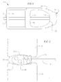
- Figure 1 shows a top view of an interbody cage 1 and an insertion rod 10.
- the cage 1 includes a substantially square and hollow main portion 2 and a nose 26.
- Bone graft with biological materials, such as morphogenic protein and derivatives, can be placed inside of the cage 1 to allow the cage 1 to be fused and incorporated into the boney structure of the adjacent vertebrae once the cage 1 is inserted.
- the insertion rod 10 projects through axial openings 12 and 14 of the back wall 16 and middle septum 18, respectively, of the cage 1.
- a distal end 20 of the insertion rod 10 abuts an internal, distal end 22 of the cage 1, and is shaped to match the internal, distal end 22 of the cage 1. This shape serves to evenly distribute an insertion force exerted by the insertion rod 10 onto the internal, distal end 22 of the cage 1.
- the middle septum 18 of the cage 1 comprises a rigid girder fixed to the interior surface of the cage 1 and located in a plane transverse to the projection of the insertion rod 10.
- the middle septum 18 serves to stabilize the insertion rod 10 and to increase the center strength of the generally hollow cage 1.
- the middle septum 18 may also include internal threads that mate with external threads on the insertion rod 10. Mating of these threads can more evenly distribute the force exerted on the insertion rod to the cage 1.
- the middle septum 18 is not included or is replaced by several girders disposed on either side of the insertion rod.
- the back wall 16 can be double welded to the back edge of the cage 1 to allow for increased vertical and horizontal strength of the cage 1.
- the opening 12 in the back wall 16 may alternatively include internal threads that can mate with external threads on the inserting rod 10. In this embodiment, the mating of the threads can aid in the insertion force transmitted from the inserting rod 10 to the cage 1.
- the cage 1 has a generally parabolic nose 26.
- the parabolic shape can aid in the distraction of the disc space between the adjacent vertebrae (shown in Figure 2) by slowly separating them vertically as the nose 26 is inserted into the disc space.
- the cage 1 has fenestrations 28, or openings, along its sides. These fenestrations allow bone graft within the main portion 2 to fuse with adjacent vertebrae outside of the cage 1.
- Cutting flutes 24 are disposed in two lines along each upper and lower sides of the nose 26.
- the cutting flutes 24 project from the nose 26 in a generally vertical direction, in a manner similar to a Sampson nail.
- the cutting flutes 24 are long enough to broach through the cartilage of the vertebral endplates and into the boney tissue.
- self-broaching refers to the interbody device's ability to broach through the cartilaginous endplates of a vertebra on its own, exposing subchondral bone.
- the flutes 24 are between 1-3 mm long.
- the nose 26 slowly distracts the disc space between the vertebrae 30 and 32 as the insertion rod 10 is pushed in the insertion direction.
- the distracting cage 1 also protects the load-bearing endplates 38 of the adjacent vertebrae 30 and 32 from damage resulting from prior art distraction and drilling methods.
- the cutting flutes 24 cut tracks 34 into the adjacent vertebrae 30 and 32.
- keel edges 35 are disposed along in two lines along each of the upper and lower sides of the main portion 2, which trail behind the cutting flutes 24 within the tracks 34 to maintain the alignment of the cage 1 with the adjacent vertebrae 30 and 32.
- cutting flutes 24 broach into the vertebrae 30 and 32, releasing blood and tissue, which aid in the fusion of the bone graft located within the cage 1.
- a front view of the nose 26 is shown in Figure 3.
- the top, bottom and side surfaces of the nose 26 are concave, with the cutting flutes 24 extending vertically outward from the center of the nose 26. This concavity allows the cutting flutes 24 to slide into the disc space with minimal friction, reducing the chances of hang up.
- the substantially parabolic, fluted nose 26 allows the cage 1 to be self-broaching and self-aligning as it is pushed into the disc space by the insertion rod 10. This allows the preliminary steps of separately distracting the disc space and/or drilling an opening in the disc space to be eliminated. A second cage can then be inserted postero-laterally into the disc space, and additional bone graft inserted between the cages.
- the nose can also include a central opening (not shown) to allow for anterior extraction or correction of the cage 1.
- a threaded insertion rod 10 is inserted through this opening and threaded into threaded openings 14 and 12 in the middle septum 18 and back wall 16, respectively. The insertion rod 10 can then be pulled anteriorly to pull the cage 1 out from the disc space or to push the cage 1 into better alignment within the disc space.
- the cutting flutes 24 of the self-broaching cage 1 can cut tracks in the adjacent vertebrae to guide the cage 1 into place and expose bleeding subchondral bone to facilitate vascular ingrowth and promote fusion.
- the cutting flutes 24 can lock the cage 1 in place after the disc space is distracted.
- a sleeve 800 may be fitted around the cage 1 to cover the fenestrations 28 and open areas of the cage 1 and to keep the bone graft from exiting the cage 1 before the cage 1 is seated between the vertebrae 30 and 32.
- the sleeve 800 is substantially the same length as the insertion rod 110.
- the sleeve 800 surrounds the cage 1 and is inserted into a surgical opening 870, directed toward the vertebrae 30 and 32, avoiding the exiting nerve root 872.
- the sleeve 800 As the cage 1 is inserted into the disc space by passing through the sleeve 800, the sleeve 800 is slowly retracted or kept in place by abutting the adjacent vertebrae, allowing the bone graft to be released in the disc space.
- the embodiment shown in Figure 8 shows a sleeve 800 with a substantially rectangular cross-section, it is within the scope of the invention to form the sleeve with any shaped cross section.
- the outer surface of the sleeve is shaped to provide easy insertion into the surgical opening or speculum (not shown), if one is present.
- the inner surface cross-sectional dimensions of the sleeve are preferably substantially the same as the outer surface dimensions of the cage, for example, extending approximately .5mm to 3mm to either side of the prosthesis, and more preferably about 1mm to ether side.
- the sleeve can be made of rigid plastic or any other suitable material, such as flexible plastic, metal, or bio-absorbable implant materials.
- the sleeve 800 can not only prevent the bone graft from escaping from the cage 1 before insertion into the disc space, but can also protect the soft tissues and nerves surrounding the insertion path from damage. Preventing pieces of bone and ortho-biological material from falling into the approach wound can be important as bone can otherwise grow spontaneously if lost in the soft tissue, particularly if it grew around an exiting segmental nerve.
- the embodiment of the snugly-fitting sleeve 800 can contain and seal the prosthesis until it has docked in the disc space, substantially avoiding the possibility of heterotropic ossification.
- the cage 100 is also progressively self-distracting. Similar to the embodiment shown in Figures 1-3, the cage 100 includes cutting flutes 124 and fenestrated side walls with upwardly projecting keel edges 135.
- the cage 100 also includes upper and lower surfaces 134 and 136 that are vertically movable relative to each other.
- the upper and lower surfaces 134 and 136 include two sets of internal threads 140 and 142, each set having a space separating them that increases toward the nose 126.
- a middle septum 118 has external threads 144 that mate with the internal threads 140 of the upper and lower surfaces 134 and 136.
- a back wall 116 also has external threads 146 that mate with the internal threads 142 of the upper and lower surfaces 134 and 136.
- Both the middle septum 118 and the back wall 116 have hexagonal central openings 114 and 112.
- An insertion rod 110 has a hexagonal cross section along its axis that, when inserted through the central openings 112 and 114 and rotated, rotates the middle septum 118 and the back wall 116 within the threads 142 and 144.
- upper and lower surfaces 134 and 136 are pushed farther away from each other.
- the surfaces 134 and 136 are pushed apart vertically, they distract the disc space further, correcting the alignment of the spine and locking the cage 100 in place between the adjacent vertebrae.
- This distraction is preferably gradual and progressive, produced by the application of measured and calibrated torque. This allows the surgeon to tailor the distraction to the individual patient and to predict with relative certainty the distraction produced by a given amount of torque. Progressive distraction additionally tightens the anatomy and ensures stability.
- Anterior opening 150 in the nose 126 allows an insertion rod 110 to be inserted from the anterior side of the spine into the cage 100. If a surgeon desires to change the distraction of the disc space or to remove or change the position of the cage 100, the insertion rod 110 can again be inserted through openings 114 and 112, and rotated to thread the back wall 116 and middle septum 118 away from the nose 126, thus collapsing the space between surfaces 134 and 136.
- an oblong cam 318 is shown that can be used in place of the threaded middle septum 118 and internal threads 140.
- Oblong cam 318 can be rotated within an internal groove (not shown) in a cage to have its longer diameter aligned vertically.
- Small slits can be made in the upper and lower surfaces through which the tips of the oblong cam 318 would extend when it is vertically aligned. Because of the force from the adjacent vertebrae when the cage is in an expanded state, the slits in the upper and lower surfaces would lock the oblong cam in vertical alignment once the tips of the oblong cam 318 pass the slits.
- a similar oblong cam can be used to replace the back wall 116 and internal threads 142 in the embodiment shown in Figure 4a.
- FIG 5 shows another embodiment of a self-broaching and self-distracting cage 200.
- Cutting flutes 224 are aligned along nose 226 in a manner similar to the embodiment shown in Figures 1-3 to allow the cage 200 to be self-broaching.
- Cage 200 also includes a threaded middle septum 218 within internal threads 240 that converge toward the nose 226, similar to the middle septum 118 shown in Figure 4a.
- the back walls 216 and 217 are formed as overlapping rectangles that each have a groove-type opening 212, allowing the insertion rod 210 to project through the overlapping area.
- the overlapping portions of back walls 216 and 217 have interlocking teeth 246.
- the interlocking teeth 246 of each of the back walls 216 and 217 project toward the other of the back walls 217 and 216 so that, when the upper and lower surfaces 234 and 236 move away from each other, they ratchet up the vertical height of the posterior side of the cage 200 until the corners of the back walls 217 and 216 indent into the adjacent vertebrae to stop the cage from extruding from the disc space.
- the force on the cage 200 from the distraction of the disc space is distributed along the main portion 202 of the cage 200, making collapse of the cage 200 due to those forces less likely.
- the insertion rod 210 can be inserted through anterior opening 250, and openings 214 and 212 to rotate the middle septum 218 so that it is threaded away from the nose 226, collapsing the center portion of the cage 200.
- the insertion rod or a screwdriver-type tool can be used that would allow a surgeon to disconnect the interlocking teeth 246 by tapping or flicking the back walls to disengage the teeth. When the teeth are disengaged, the force on the back walls would then bend them into a V-shape after the center portion of the cage 200 is collapsed.
- the fenestrated walls of the cage can be cut or stamped out from metal or absorbable biological material mesh prior to cage formation.
- the metal would be titanium, stainless steel, alloys or carbon fiber. Alloys such as porous titanium-nickel alloy have been shown to promote rapid tissue ingrowth.
- the cutting flutes or keel pieces can be formed by cutting the fenestrated metal in a line that passes through several of the fenestrations. This results in an edge with several sharp protrusions. This edge can then be electrostatically welded to another similar edge for increased strength.
- the dimensions of the cages and insertion rods can be varied for the desired result, it has been found that a length of between 22mm and 30mm, a height of between 8 mm and 19mm, and a transverse diameter of 8mm to 12mm is ideal.
- the cages are preferably of graduated sizes to accommodate the variation of human anatomical size.
- the vertical height in the distracting embodiments may increase an additional 1.5mm in each direction.
- FIG. 6 shows another embodiment of a self-distracting cage 400.
- the cage 400 is formed from two wedge-shaped, hollow portions 434 and 436.
- a screw 460 projects through internal threads in the anterior and posterior openings 450 and 412 and has a screw head 462 and 464 at both ends so that the screw 460 cannot disengage with the threads of either opening 450 or 412.
- the screw heads 462 and 464 can mate a screw driver (not shown) to be rotated while inside of the disc space. As the screw 460 is rotated within the threads of openings 450 and 412, the wedge-shaped portions 434 and 436 slide over each other and distract the disc space. The screw heads 462 and 464 can be rotated either posteriorly or anteriorly to distract or collapse the disc space.
- FIGs 7a and 7b show an alternate embodiment of the slip-wedge cage shown in Figure 6.
- the cage 500 has domed and self-broaching wedge-shaped portions 534 and 536.
- Cutting flutes 524 project vertically in two lines along each of the top and bottom wedge-shaped portions 534 and 536, similar to the cutting flutes of the previous embodiments.
- the wedge-shaped portions 534 and 536 have only a minimal overlap, to ensure that the cage can be inserted into the disc space with its self-broaching cutting flutes 524 with minimal resistance.
- the screw 560 can be rotated by a screw driver (not shown) to pull the wedge-shaped portions toward each other, to distract the disc space.
- the dome shaped portions 534 and 536 allow the force of distraction to be evenly distributed across the cage, making unintentional collapse less likely.
- reflective fiducials can be added to the cage and the insertion rod to allow them to be used in image guided surgery.
Abstract
Description
- As the lumbar spine ages, disc degeneration occurs. This degeneration causes a reduction in the vertical height of the disc, and a diminution of its viscoelastic properties. The profile of the spine also changes with age. The swayback curvature of youth becomes the flat-back of old age. This results in increased biomechanical stress on the posterior side of the spine.
- With a recent increased understanding in the biomechanics of the spine, it is acknowledged that maintenance of the normal curvature of the lumbar spine is preferable. When spinal fusions are considered, it is important to re-establish the normal biomechanical arrangement, and to restore the sagittal profile of the spine to obtain optimal results. Arthritic changes in the facet joints following disc degeneration can cause mechanical back pain. If they become excessive, these arthritic changes can cause spinal stenosis.
- For these reasons, several prior art techniques have been used that remove the degenerated disc, distract the disc space, and rigidly bond the upper and lower adjacent vertebrae together. Initially, this was accomplished by inserting pieces of bone having cortex and marrow cut from solid bone locations, such as the wing of the pelvis or the fibula. Such grafts were only able to support around 430 1bs. of force within the disc space, however, and compression forces up to 1,850 lbs. can be experienced by a human when, for example, bending over to pick up a 25 1b. child. After experiencing such high compression forces, these grafts tended to collapse and lose their ability to fix and stabilize the spinal motion segment by distracting the disc space.
- To deal with this problem, metal cages packed with bone or ortho-biological compounds (osteoinductive/osteoconductive) capable of fusing with the adjacent vertebrae were inserted in the distracted disc space. Such cages were able to withstand the larger compression forces while allowing the bone inside of the cages to fuse with the adjacent vertebrae. The cages were typically constructed of titanium mesh cylinders, screw-in bullet-like metal cages with external threads, or rectangular cages made of carbon fiber.
- These cages were typically inserted into the disc space after the space had been distracted and/or drilled by a separate tool to form a niche for the cage and to broach through the cartilage and into the boney tissue to promote fusion. For purposes of this disclosure "broaching" refers to cutting through the cartilage of adjacent vertebral endplates and into the boney tissue of the vertebrae. The process of separately broaching and distracting the disc space, however, requires multiple steps of inserting and removing various drills, broaches and/or distracters into the disc space, causing direct or indirect damage to the load-bearing endplates of the adjacent vertebrae, weakening them and jeopardizing the fixation of the interbody fusion construction.
- Because of the openings in the cages, another problem with the prior art cages were that small pieces of bone or ortho-biological material were capable of spilling out of the cage and into the soft tissue surrounding the surgical opening before the cage was placed between the vertebral endplates. In this case, heterotrophic ossification, or bone growth, could occur in the access port of the surgical wound or possibly near the exiting segmental nerve, resulting in bony nerve entrapment and tremendous pain and complications.
- Other prior art methods of distracting the disc space included inserting a semi-rigid, U-shaped object with internal teeth. A round object with a larger diameter than the interior space of the object was then inserted into the interior space between facing interior teeth. By moving the round object further into the interior of the object, the legs of the U-shaped object were pushed apart, thereby distracting the disc space. These U-shaped devices, however, typically broke due to the forces exerted by the round object and the adjacent vertebrae.
- In addition to the above problems with inserting the prior art cages, the cages are susceptible to movement within the disc space once they are inserted. This movement can damage the biological growth of the fusion, due to shear forces on the vascular ingrowth nourishing the endosteal bone growth - limiting the development of fusion of the bone inside of the cage which is necessary to stabilize the adjacent vertebrae, resulting in looseness and bone graft collapse. To this effect, several prior art cages were constructed with short spikes or points to stabilize them within the disc space, but which were not long enough to broach through the cartilage into the boney tissue of the vertebrae.
- Moreover, if the compression forces are not withstood and the disc space is not held in a distracted state by a strong cage, the cage may collapse, leading to looseness, instability and further failure of fusion due to movement. However, if the cage is overly rigid and strong, such as a threaded cage, it may shield the bone inside of the cage from the normal stresses and strains that bone needs to develop into weight bearing, trabecular bone, which will fuse with the adjacent vertebrae in a strong and rigid fashion. This failure to satisfactorily promote fusion may also lead to looseness and instability of the cage or fusion construct.
- Therefore, a need exists to provide an interbody device or a method of inserting such a device that solves one or more of the problems described above.
- The current invention is directed to a system and method for fusing a first and second vertebrae. In one embodiment, the vertebrae are fused by inserting a self-broaching interbody device into a disc space without the need for separately drilling and broaching. The self-broaching interbody device may include cutting flutes or other broaching means capable of cutting through the cartilaginous endplates of the vertebrae ~ exposing subchondial bone, facilitating fusion development.
- In another embodiment, an interbody device with an expanding means is inserted into the disc space. The expanding means is capable of moving the interbody device from an unexpanded state, where the upper and lower surfaces of the interbody device are at a first distance from each other, to an expanded state, where the upper and lower surfaces are at a second and greater distance from each other. In the unexpanded state, the interbody device can be inserted between the vertebrae while they are in an undistracted state without the need for previously distracting the disc space. In the expanded state, the inserted interbody device can force the first and second vertebrae into a distracted state.
- Yet another embodiment includes a sleeve that fits around an interbody device that has at least one opening in its outer surface leading to a cavity. Bone graft and/or ortho-biological materials capable of fusing with the vertebrae are contained within the sleeve's cavity. The sleeve is configured to fit around the interbody device so that the biological materials are kept within the cavity while the interbody device is within the sleeve. The interbody device can then by moved completely through the sleeve to rest between the vertebrae.
- These and other features and advantages of the present invention will be better understood by reference to the following detailed description when considered in conjunction with the accompanying drawings where:
- Figure 1 is a top view of one embodiment of an interbody system according to the invention;
- Figure 2 is a side view of the embodiment shown in Figure 1, inserted into adjacent vertebrae;
- Figure 3 is a front view of the nose of the embodiment shown in Figures 1 and 2;
- Figure 4a is a side cross-sectional view of another embodiment of an interbody system according to the invention;
- Figure 4b is a front perspective view of an end of the insertion rod shown in Figure 4a;
- Figure 4c is a top view of the embodiment shown in Figure 4a;
- Figure 4d is an alternate embodiment of the middle septum shown in Figure 4a;
- Figure 5 is a side cross-sectional view of another embodiment of an interbody cage system according to the invention;
- Figure 6 is a side perspective view of yet another embodiment of an interbody cage system according to the invention;
- Figure 7a is a side perspective view of still yet another embodiment of an interbody cage system according to the invention in an unexpanded state;
- Figure 7b is a side perspective view of the embodiment shown in Figure 7a in an expanded state; and
- Figure 8 is a side perspective view of an alternate embodiment of the invention inserted into a surgical opening toward the spine.
- Figure 1 shows a top view of an
interbody cage 1 and aninsertion rod 10. Thecage 1 includes a substantially square and hollow main portion 2 and anose 26. Bone graft with biological materials, such as morphogenic protein and derivatives, can be placed inside of thecage 1 to allow thecage 1 to be fused and incorporated into the boney structure of the adjacent vertebrae once thecage 1 is inserted. - The insertion rod 10 projects through
axial openings back wall 16 andmiddle septum 18, respectively, of thecage 1. Adistal end 20 of theinsertion rod 10 abuts an internal,distal end 22 of thecage 1, and is shaped to match the internal,distal end 22 of thecage 1. This shape serves to evenly distribute an insertion force exerted by theinsertion rod 10 onto the internal,distal end 22 of thecage 1. - The
middle septum 18 of thecage 1 comprises a rigid girder fixed to the interior surface of thecage 1 and located in a plane transverse to the projection of theinsertion rod 10. Themiddle septum 18 serves to stabilize theinsertion rod 10 and to increase the center strength of the generallyhollow cage 1. Themiddle septum 18 may also include internal threads that mate with external threads on theinsertion rod 10. Mating of these threads can more evenly distribute the force exerted on the insertion rod to thecage 1. In other embodiments of the cage, themiddle septum 18 is not included or is replaced by several girders disposed on either side of the insertion rod. - The
back wall 16 can be double welded to the back edge of thecage 1 to allow for increased vertical and horizontal strength of thecage 1. Theopening 12 in theback wall 16 may alternatively include internal threads that can mate with external threads on the insertingrod 10. In this embodiment, the mating of the threads can aid in the insertion force transmitted from the insertingrod 10 to thecage 1. - In this embodiment, the
cage 1 has a generallyparabolic nose 26. The parabolic shape can aid in the distraction of the disc space between the adjacent vertebrae (shown in Figure 2) by slowly separating them vertically as thenose 26 is inserted into the disc space. - As shown in the side view of Figure 2, the
cage 1 hasfenestrations 28, or openings, along its sides. These fenestrations allow bone graft within the main portion 2 to fuse with adjacent vertebrae outside of thecage 1. - Cutting
flutes 24 are disposed in two lines along each upper and lower sides of thenose 26. The cutting flutes 24 project from thenose 26 in a generally vertical direction, in a manner similar to a Sampson nail. The cutting flutes 24 are long enough to broach through the cartilage of the vertebral endplates and into the boney tissue. For purposes of this disclosure, "self-broaching" refers to the interbody device's ability to broach through the cartilaginous endplates of a vertebra on its own, exposing subchondral bone. In one embodiment, theflutes 24 are between 1-3 mm long. By broaching into the vertebrae, thecage 1 can allow the blood and tissue from the adjacent vertebrae to mix with the bone graft within thecage 1 to promote fusion. - As the
cage 1 is inserted postero-laterally in the disc space between upper and loweradjacent vertebrae nose 26 slowly distracts the disc space between thevertebrae insertion rod 10 is pushed in the insertion direction. Thedistracting cage 1 also protects the load-bearingendplates 38 of theadjacent vertebrae - As the
cage 1 slides along the adjacent vertebrae, the cuttingflutes 24 cut tracks 34 into theadjacent vertebrae flutes 24 within thetracks 34 to maintain the alignment of thecage 1 with theadjacent vertebrae tracks 34 for alignment purposes, cuttingflutes 24 broach into thevertebrae cage 1. - A front view of the
nose 26 is shown in Figure 3. The top, bottom and side surfaces of thenose 26 are concave, with the cuttingflutes 24 extending vertically outward from the center of thenose 26. This concavity allows the cuttingflutes 24 to slide into the disc space with minimal friction, reducing the chances of hang up. - The substantially parabolic,
fluted nose 26 allows thecage 1 to be self-broaching and self-aligning as it is pushed into the disc space by theinsertion rod 10. This allows the preliminary steps of separately distracting the disc space and/or drilling an opening in the disc space to be eliminated. A second cage can then be inserted postero-laterally into the disc space, and additional bone graft inserted between the cages. - The nose can also include a central opening (not shown) to allow for anterior extraction or correction of the
cage 1. In this embodiment, a threadedinsertion rod 10 is inserted through this opening and threaded into threadedopenings middle septum 18 andback wall 16, respectively. Theinsertion rod 10 can then be pulled anteriorly to pull thecage 1 out from the disc space or to push thecage 1 into better alignment within the disc space. - In this embodiment, the cutting
flutes 24 of the self-broachingcage 1 can cut tracks in the adjacent vertebrae to guide thecage 1 into place and expose bleeding subchondral bone to facilitate vascular ingrowth and promote fusion. In addition, the cuttingflutes 24 can lock thecage 1 in place after the disc space is distracted. - A
sleeve 800, shown in Figure 8, may be fitted around thecage 1 to cover thefenestrations 28 and open areas of thecage 1 and to keep the bone graft from exiting thecage 1 before thecage 1 is seated between thevertebrae sleeve 800 is substantially the same length as theinsertion rod 110. Thesleeve 800 surrounds thecage 1 and is inserted into asurgical opening 870, directed toward thevertebrae nerve root 872. As thecage 1 is inserted into the disc space by passing through thesleeve 800, thesleeve 800 is slowly retracted or kept in place by abutting the adjacent vertebrae, allowing the bone graft to be released in the disc space. - Although the embodiment shown in Figure 8 shows a
sleeve 800 with a substantially rectangular cross-section, it is within the scope of the invention to form the sleeve with any shaped cross section. Preferably, the outer surface of the sleeve is shaped to provide easy insertion into the surgical opening or speculum (not shown), if one is present. The inner surface cross-sectional dimensions of the sleeve are preferably substantially the same as the outer surface dimensions of the cage, for example, extending approximately .5mm to 3mm to either side of the prosthesis, and more preferably about 1mm to ether side. - The sleeve can be made of rigid plastic or any other suitable material, such as flexible plastic, metal, or bio-absorbable implant materials. In this embodiment, the
sleeve 800 can not only prevent the bone graft from escaping from thecage 1 before insertion into the disc space, but can also protect the soft tissues and nerves surrounding the insertion path from damage. Preventing pieces of bone and ortho-biological material from falling into the approach wound can be important as bone can otherwise grow spontaneously if lost in the soft tissue, particularly if it grew around an exiting segmental nerve. Thus, the embodiment of the snugly-fitting sleeve 800 can contain and seal the prosthesis until it has docked in the disc space, substantially avoiding the possibility of heterotropic ossification. - In the embodiment shown in Figures 4a-4c, the
cage 100 is also progressively self-distracting. Similar to the embodiment shown in Figures 1-3, thecage 100 includes cuttingflutes 124 and fenestrated side walls with upwardly projecting keel edges 135. Thecage 100 also includes upper andlower surfaces lower surfaces internal threads nose 126. Amiddle septum 118 hasexternal threads 144 that mate with theinternal threads 140 of the upper andlower surfaces back wall 116 also hasexternal threads 146 that mate with theinternal threads 142 of the upper andlower surfaces - Both the
middle septum 118 and theback wall 116 have hexagonalcentral openings insertion rod 110 has a hexagonal cross section along its axis that, when inserted through thecentral openings middle septum 118 and theback wall 116 within thethreads middle septum 118 andback wall 116 are threaded closer to thenose 126, upper andlower surfaces surfaces cage 100 in place between the adjacent vertebrae. This distraction is preferably gradual and progressive, produced by the application of measured and calibrated torque. This allows the surgeon to tailor the distraction to the individual patient and to predict with relative certainty the distraction produced by a given amount of torque. Progressive distraction additionally tightens the anatomy and ensures stability. -
Anterior opening 150 in thenose 126 allows aninsertion rod 110 to be inserted from the anterior side of the spine into thecage 100. If a surgeon desires to change the distraction of the disc space or to remove or change the position of thecage 100, theinsertion rod 110 can again be inserted throughopenings back wall 116 andmiddle septum 118 away from thenose 126, thus collapsing the space betweensurfaces - In Figure 4d, an
oblong cam 318 is shown that can be used in place of the threadedmiddle septum 118 andinternal threads 140.Oblong cam 318 can be rotated within an internal groove (not shown) in a cage to have its longer diameter aligned vertically. Small slits can be made in the upper and lower surfaces through which the tips of theoblong cam 318 would extend when it is vertically aligned. Because of the force from the adjacent vertebrae when the cage is in an expanded state, the slits in the upper and lower surfaces would lock the oblong cam in vertical alignment once the tips of theoblong cam 318 pass the slits. A similar oblong cam can be used to replace theback wall 116 andinternal threads 142 in the embodiment shown in Figure 4a. - Figure 5 shows another embodiment of a self-broaching and self-distracting
cage 200. Cuttingflutes 224 are aligned alongnose 226 in a manner similar to the embodiment shown in Figures 1-3 to allow thecage 200 to be self-broaching.Cage 200 also includes a threadedmiddle septum 218 withininternal threads 240 that converge toward thenose 226, similar to themiddle septum 118 shown in Figure 4a. - In this embodiment, the
back walls type opening 212, allowing theinsertion rod 210 to project through the overlapping area. The overlapping portions ofback walls teeth 246. The interlockingteeth 246 of each of theback walls back walls lower surfaces cage 200 until the corners of theback walls - By locking the vertical height of the posterior side of the
cage 200, the force on thecage 200 from the distraction of the disc space is distributed along themain portion 202 of thecage 200, making collapse of thecage 200 due to those forces less likely. - If a surgeon wishes to remove the
cage 200, theinsertion rod 210 can be inserted throughanterior opening 250, andopenings middle septum 218 so that it is threaded away from thenose 226, collapsing the center portion of thecage 200. The insertion rod or a screwdriver-type tool can be used that would allow a surgeon to disconnect the interlockingteeth 246 by tapping or flicking the back walls to disengage the teeth. When the teeth are disengaged, the force on the back walls would then bend them into a V-shape after the center portion of thecage 200 is collapsed. - In each of the embodiments discussed above, the fenestrated walls of the cage can be cut or stamped out from metal or absorbable biological material mesh prior to cage formation. Preferably, the metal would be titanium, stainless steel, alloys or carbon fiber. Alloys such as porous titanium-nickel alloy have been shown to promote rapid tissue ingrowth.
- The cutting flutes or keel pieces can be formed by cutting the fenestrated metal in a line that passes through several of the fenestrations. This results in an edge with several sharp protrusions. This edge can then be electrostatically welded to another similar edge for increased strength.
- Although one skilled in the art will understand that the dimensions of the cages and insertion rods can be varied for the desired result, it has been found that a length of between 22mm and 30mm, a height of between 8 mm and 19mm, and a transverse diameter of 8mm to 12mm is ideal. The cages are preferably of graduated sizes to accommodate the variation of human anatomical size. The vertical height in the distracting embodiments may increase an additional 1.5mm in each direction.
- Figure 6 shows another embodiment of a self-distracting
cage 400. In this embodiment, thecage 400 is formed from two wedge-shaped,hollow portions screw 460 projects through internal threads in the anterior andposterior openings screw head screw 460 cannot disengage with the threads of eitheropening - The screw heads 462 and 464 can mate a screw driver (not shown) to be rotated while inside of the disc space. As the
screw 460 is rotated within the threads ofopenings portions - Figures 7a and 7b show an alternate embodiment of the slip-wedge cage shown in Figure 6. In this embodiment, the cage 500 has domed and self-broaching wedge-shaped portions 534 and 536. Cutting
flutes 524 project vertically in two lines along each of the top and bottom wedge-shaped portions 534 and 536, similar to the cutting flutes of the previous embodiments. - As the cage 500 is being inserted between adjacent vertebrae, the wedge-shaped portions 534 and 536 have only a minimal overlap, to ensure that the cage can be inserted into the disc space with its self-broaching
cutting flutes 524 with minimal resistance. Once the cage is between theadjacent vertebrae screw 560 can be rotated by a screw driver (not shown) to pull the wedge-shaped portions toward each other, to distract the disc space. The dome shaped portions 534 and 536 allow the force of distraction to be evenly distributed across the cage, making unintentional collapse less likely. - In each of the embodiments discussed above, reflective fiducials can be added to the cage and the insertion rod to allow them to be used in image guided surgery.
- Although specific embodiments are disclosed herein, it is expected that persons skilled in the art can and will design alternate embodiments and methods that are within the scope of the following claims either literally or under the doctrine of equivalents.
Claims (34)
- An spinal fusion system for fusing two adjacent vertebrae, comprising a self-broaching interbody apparatus with an inside surface, an outside surface, an insertion end and a trailing end, the interbody apparatus configured to be inserted between said adjacent vertebrae.
- The spinal fusion system of claim 1, wherein the insertion end includes cutting flutes, the cutting flutes projecting from the outside surface in a first direction and configured to cut through a cartilage layer on at least one of said adjacent vertebrae.
- The spinal fusion system of claim 2, further comprising a keel projecting in substantially the first direction, fixed to the outside surface and aligned behind at least one of the cutting flutes.
- The spinal fusion system of claim 1, wherein the trailing end includes an edge that projects at least partially outward, such that when the interbody apparatus sits between said adjacent vertebrae, the edge exerts force on said adjacent vertebrae.
- The spinal fusion system of claim 1, wherein the interbody apparatus further comprises an upper surface, a lower surface and an expanding means,
wherein the expanding means is capable of moving the interbody apparatus from an unexpanded state, where the upper and lower surfaces are at a first distance from each other, to an expanded state, where the upper and lower surfaces are at a second and greater distance from each other. - An spinal fusion system for fusing a first and second adjacent vertebrae, comprising a sleeve with an insertion end, a trailing end, an inside surface and an outside surface, the inside surface sized to contain an interbody apparatus, the outside surface sized to be insertable into a surgical opening, and the insertion end and the trailing end having openings.
- The spinal fusion system of claim 6, wherein a distance between the inside surface of the sleeve and an outer surface of the interbody apparatus is approximately .5mm to 3mm.
- The spinal fusion system of claim 6, wherein a distance between the inside surface of the sleeve and an outer surface of the interbody apparatus is approximately 1mm.
- The spinal fusion system of claim 6, further comprising an interbody apparatus with an outside surface, the interbody apparatus configured to fit within the inside surface of the sleeve and able to slide through the insertion end opening of the sleeve.
- The spinal fusion system of claim 9, further comprising a substantially rigid insertion rod sized to fit through the trailing end opening of the sleeve.
- The spinal fusion system of claim 10, wherein the sleeve is approximately the same length as the insertion rod.
- The spinal fusion system of claim 9, wherein the outer surface of the interbody apparatus comprises an opening into a body cavity that contains at least one of bone and ortho-biological materials capable of fusing with said adjacent vertebrae,
and wherein the inner surface of the sleeve fits around the outer surface of the interbody apparatus such that the openings are enclosed by the sleeve and the at least one of bone and ortho-biological materials are kept substantially within the cavity. - The spinal fusion system of claim 9, wherein the interbody apparatus is self-broaching.
- The spinal fusion system of claim 6, wherein the sleeve comprises plastic.
- The spinal fusion system of claim 6, wherein the sleeve comprises metal.
- The spinal fusion system of claim 6, wherein the sleeve comprises bio-absorbable material.
- The spinal fusion system of claim 6, wherein the sleeve is rigid.
- The spinal fusion system of claim 17, wherein the outer surface of the sleeve at the insertion end is larger than a distance between said adjacent vertebrae.
- The spinal fusion system of claim 6, wherein the sleeve is flexible.
- An spinal fusion system for fusing two adjacent vertebrae, comprising:an interbody apparatus with an upper surface, a lower surface, an insertion end and a trailing end; andan expanding means capable of moving the interbody apparatus from an unexpanded state, where the upper and lower surfaces are at a first distance from each other, to an expanded state, where the upper and lower surfaces are at a second and greater distance from each other,
wherein in the unexpanded state, the interbody apparatus can be inserted between said adjacent vertebrae while a distance between the adjacent vertebrae is in an undistracted state, and
wherein in the expanded state, the interbody apparatus can force the distance between the adjacent vertebrae into a distracted state. - The spinal fusion system of claim 20, wherein the expanding means comprises:upper internal threads fixed to the upper surface and projecting toward the lower surface, the length of the upper internal threads increasing toward the insertion end;lower internal threads fixed to the lower surface and projecting toward the upper surface, the length of the lower internal threads increasing toward the insertion end; anda disc having external threads mated with the upper and lower internal threads, such that when the disc is threaded toward the insertion end, the upper and lower surfaces are pushed apart.
- The spinal fusion system of claim 21, wherein the expanding means further comprises:rear upper internal threads fixed to the upper surface near the trailing end and projecting toward the lower surface, the length of the rear upper internal threads increasing toward the insertion end;rear lower internal threads fixed to the lower surface near the trailing end and projecting toward the upper surface, the length of the rear lower internal threads increasing toward the insertion end; anda back wall disc having external threads mated with the rear upper and rear lower internal threads, such that when the back wall disc is threaded toward the insertion end, the rear upper and rear lower surfaces are pushed apart.
- The spinal fusion system of claim 21, wherein the expanding means further comprises:an upper back wall fixed to the upper surface near the trailing end, the upper back wall projecting toward the lower surface and including upper ratchets; anda lower back wall fixed to the lower surface near the trailing end, the lower back wall projecting toward the upper surface and including lower ratchets, the lower back wall overlapping with the upper back wall in an area of overlap,
wherein the upper ratchets and lower ratchets project toward each other and interlock, such that when the upper and lower surfaces are moved toward the expanded state, the upper ratchets and lower ratchets interlock with a decreasing area of overlap. - The spinal fusion system of claim 21, wherein the disc has an opening, the expanding means further comprising an insertion rod configured to fit within the opening such that when it is rotated, the disc rotates with it.
- The spinal fusion system of claim 20, wherein the expanding means further comprises:a first oblong cam having a first major radius, the first cam in a substantially perpendicular plane to the upper and lower surfaces inside of the interbody apparatus and rotatable within first grooves in the upper and lower surfaces,
wherein the first cam is shaped such that when it is rotated, the interbody apparatus moves between an expanded state, where the first major radius points toward the upper and lower surfaces and pushes them away from each other, to an unexpanded state, where the first major radius points away from the upper and lower surfaces. - The spinal fusion system of claim 25, wherein the expanding means further comprises:a second oblong cam having a second major radius, the second cam in a substantially perpendicular plane to the upper and lower surfaces inside of the interbody apparatus and rotatable within grooves near the trailing end in the upper and lower surfaces,
wherein the second cam is shaped such that when it is rotated, the interbody apparatus moves between an expanded state, where the second major radius points toward the upper and lower surfaces and pushes them away from each other, to an unexpanded state, where the second major radius points away from the upper and lower surfaces. - The spinal fusion system of claim 25, wherein the expanding means further comprises:an upper back wall fixed to the upper surface near the trailing end, the upper back wall projecting toward the lower surface and including upper ratchets; anda lower back wall fixed to the lower surface near the trailing end, the lower back wall projecting toward the upper surface and including lower ratchets, the lower back wall overlapping with the upper back wall in an area of overlap,
wherein the upper ratchets and lower ratchets project toward each other and interlock, such that when the upper and lower surfaces are moved toward the expanded state, the upper ratchets and lower ratchets interlock with a decreasing area of overlap. - The spinal fusion system of claim 25, wherein the upper surface includes an upper slit and the lower surface includes a lower slit, the upper and lower slits located such that the first oblong cam projects at least partially through the upper and lower slits when the interbody apparatus is in the expanded state.
- The spinal fusion system of claim 25, wherein the first cam has an opening, the expanding means further comprising an insertion rod configured to fit within the opening such that when it is rotated, the first cam rotates with it.
- The spinal fusion system of claim 20, wherein the expanding means further comprises:a first end wall projecting from the upper surface on one of the insertion end and the trailing end toward the lower surface and having a first opening with internal threads;a second end wall projecting from the lower surface on the other of the insertion end and the trailing end toward the upper surface and having a second opening with internal threads;first and second sidewalls having first and second projecting edges, the first and second sidewalls fixed to the upper surface and the first end wall, and increasing in size toward the first end wall;third and fourth sidewalls having third and fourth projecting edges, the third and forth sidewalls fixed to the lower surface and the second end wall, and increasing in size toward the second sidewall;a second end wall projecting from the lower surface on the other of the insertion end and the trailing end toward the upper surface, the second end wall coupled to the third and fourth sidewalls and having an opening with internal threads; anda linking screw with external threads that mate with the internal threads of the first and second end walls such that the first and second end walls are pulled toward each other when the linking screw is rotated,
wherein the first and third projecting edges slide against each other and the second and fourth projecting edges slide against each other when the linking screw is rotated. - The spinal fusion system of claim 30, wherein the upper and lower surfaces are curved to mate with said adjacent vertebrae.
- A method for fusing two adjacent vertebrae having respectively first and second facing cartilaginous endplates, the method comprising:providing a self-broaching interbody apparatus configured to be inserted between said adjacent vertebrae; andinserting the interbody apparatus between the adjacent vertebrae, such that the interbody apparatus broaches through at least one of said first and second cartilaginous endplates as it is being.inserted.
- A method for fusing two adjacent vertebrae having an undistracted state and a distracted state, comprising:providing an interbody apparatus having an unexpanded state and an expanded state;inserting the interbody apparatus in the unexpanded state between said adjacent vertebrae while said adjacent vertebrae are in an undistracted state; andmoving the interbody apparatus to the expanded state after inserting to move the adjacent vertebrae to a distracted state.
- A method for fusing two adjacent vertebrae, comprising:providing an interbody apparatus having at least one cavity therein that opens to an outer surface of the interbody apparatus, the cavity containing at least one of bone and ortho-biological material capable of producing a fusion between said adjacent vertebrae;providing a sleeve configured to at least partially surround the interbody apparatus and hold the at least one of bone and ortho-biological material within the cavity;positioning the sleeve at an opening between said adjacent vertebrae; andmoving the interbody apparatus completely through the sleeve and between said adjacent vertebrae.
Applications Claiming Priority (1)
| Application Number | Priority Date | Filing Date | Title |
|---|---|---|---|
| US10/940,570 US7799081B2 (en) | 2004-09-14 | 2004-09-14 | System and method for spinal fusion |
Publications (2)
| Publication Number | Publication Date |
|---|---|
| EP1634549A2 true EP1634549A2 (en) | 2006-03-15 |
| EP1634549A3 EP1634549A3 (en) | 2006-05-17 |
Family
ID=35448068
Family Applications (1)
| Application Number | Title | Priority Date | Filing Date |
|---|---|---|---|
| EP05077059A Withdrawn EP1634549A3 (en) | 2004-09-14 | 2005-09-09 | System and method for spinal fusion |
Country Status (2)
| Country | Link |
|---|---|
| US (2) | US7799081B2 (en) |
| EP (1) | EP1634549A3 (en) |
Cited By (5)
| Publication number | Priority date | Publication date | Assignee | Title |
|---|---|---|---|---|
| EP1941847A1 (en) * | 2007-01-05 | 2008-07-09 | Orthopaedic & Spine Development | Expandable/compressible intervertebral prosthesis |
| WO2011066077A3 (en) * | 2009-11-24 | 2011-09-29 | Spine21 Ltd. | Spinal fusion cage having post-operative adjustable dimensions |
| US8097037B2 (en) | 2006-12-20 | 2012-01-17 | Depuy Spine, Inc. | Methods and devices for correcting spinal deformities |
| WO2014146797A1 (en) * | 2013-03-22 | 2014-09-25 | Joimax Gmbh | Instrument set and method for introducing a cage into the intervertebral disc space |
| US9456908B2 (en) | 2013-03-12 | 2016-10-04 | Coorstek Medical Llc | Fusion cage |
Families Citing this family (317)
| Publication number | Priority date | Publication date | Assignee | Title |
|---|---|---|---|---|
| US6206922B1 (en) * | 1995-03-27 | 2001-03-27 | Sdgi Holdings, Inc. | Methods and instruments for interbody fusion |
| FR2897259B1 (en) | 2006-02-15 | 2008-05-09 | Ldr Medical Soc Par Actions Si | INTERSOMATIC TRANSFORAMINAL CAGE WITH INTERBREBAL FUSION GRAFT AND CAGE IMPLANTATION INSTRUMENT |
| FR2824261B1 (en) | 2001-05-04 | 2004-05-28 | Ldr Medical | INTERVERTEBRAL DISC PROSTHESIS AND IMPLEMENTATION METHOD AND TOOLS |
| FR2827156B1 (en) | 2001-07-13 | 2003-11-14 | Ldr Medical | VERTEBRAL CAGE DEVICE WITH MODULAR FASTENING |
| US6793678B2 (en) | 2002-06-27 | 2004-09-21 | Depuy Acromed, Inc. | Prosthetic intervertebral motion disc having dampening |
| FR2846550B1 (en) | 2002-11-05 | 2006-01-13 | Ldr Medical | INTERVERTEBRAL DISC PROSTHESIS |
| CN1774220A (en) | 2003-02-14 | 2006-05-17 | 德普伊斯派尔公司 | In-situ formed intervertebral fusion device and method |
| US20040267367A1 (en) | 2003-06-30 | 2004-12-30 | Depuy Acromed, Inc | Intervertebral implant with conformable endplate |
| FR2865629B1 (en) | 2004-02-04 | 2007-01-26 | Ldr Medical | INTERVERTEBRAL DISC PROSTHESIS |
| RU2354334C2 (en) | 2004-02-04 | 2009-05-10 | Лдр Медикаль | Intervertebral disc prosthesis |
| US8016829B2 (en) | 2004-02-09 | 2011-09-13 | Depuy Spine, Inc. | Systems and methods for spinal surgery |
| US8636802B2 (en) | 2004-03-06 | 2014-01-28 | DePuy Synthes Products, LLC | Dynamized interspinal implant |
| US8992618B2 (en) | 2004-04-26 | 2015-03-31 | DePuy Synthes Products, LLC | Intervertebral prosthesis or disk prosthesis |
| FR2869528B1 (en) | 2004-04-28 | 2007-02-02 | Ldr Medical | INTERVERTEBRAL DISC PROSTHESIS |
| US8470004B2 (en) | 2004-08-09 | 2013-06-25 | Si-Bone Inc. | Apparatus, systems, and methods for stabilizing a spondylolisthesis |
| US8425570B2 (en) | 2004-08-09 | 2013-04-23 | Si-Bone Inc. | Apparatus, systems, and methods for achieving anterior lumbar interbody fusion |
| US8388667B2 (en) | 2004-08-09 | 2013-03-05 | Si-Bone, Inc. | Systems and methods for the fixation or fusion of bone using compressive implants |
| US20060036251A1 (en) | 2004-08-09 | 2006-02-16 | Reiley Mark A | Systems and methods for the fixation or fusion of bone |
| US20070156241A1 (en) | 2004-08-09 | 2007-07-05 | Reiley Mark A | Systems and methods for the fixation or fusion of bone |
| US9949843B2 (en) | 2004-08-09 | 2018-04-24 | Si-Bone Inc. | Apparatus, systems, and methods for the fixation or fusion of bone |
| US9662158B2 (en) | 2004-08-09 | 2017-05-30 | Si-Bone Inc. | Systems and methods for the fixation or fusion of bone at or near a sacroiliac joint |
| US20180228621A1 (en) | 2004-08-09 | 2018-08-16 | Mark A. Reiley | Apparatus, systems, and methods for the fixation or fusion of bone |
| US8444693B2 (en) | 2004-08-09 | 2013-05-21 | Si-Bone Inc. | Apparatus, systems, and methods for achieving lumbar facet fusion |
| US8414648B2 (en) | 2004-08-09 | 2013-04-09 | Si-Bone Inc. | Apparatus, systems, and methods for achieving trans-iliac lumbar fusion |
| US8236029B2 (en) | 2004-08-11 | 2012-08-07 | Nlt Spine Ltd. | Devices for introduction into a body via a substantially straight conduit to for a predefined curved configuration, and methods employing such devices |
| US7799081B2 (en) | 2004-09-14 | 2010-09-21 | Aeolin, Llc | System and method for spinal fusion |
| WO2006034436A2 (en) | 2004-09-21 | 2006-03-30 | Stout Medical Group, L.P. | Expandable support device and method of use |
| US8597360B2 (en) | 2004-11-03 | 2013-12-03 | Neuropro Technologies, Inc. | Bone fusion device |
| WO2006058221A2 (en) | 2004-11-24 | 2006-06-01 | Abdou Samy M | Devices and methods for inter-vertebral orthopedic device placement |
| FR2879436B1 (en) | 2004-12-22 | 2007-03-09 | Ldr Medical | INTERVERTEBRAL DISC PROSTHESIS |
| US7655046B2 (en) * | 2005-01-20 | 2010-02-02 | Warsaw Orthopedic, Inc. | Expandable spinal fusion cage and associated instrumentation |
| US7942903B2 (en) | 2005-04-12 | 2011-05-17 | Moskowitz Ahmnon D | Bi-directional fixating transvertebral body screws and posterior cervical and lumbar interarticulating joint calibrated stapling devices for spinal fusion |
| US11903849B2 (en) | 2005-04-12 | 2024-02-20 | Moskowitz Family Llc | Intervertebral implant and tool assembly |
| US9848993B2 (en) | 2005-04-12 | 2017-12-26 | Nathan C. Moskowitz | Zero-profile expandable intervertebral spacer devices for distraction and spinal fusion and a universal tool for their placement and expansion |
| US7674296B2 (en) | 2005-04-21 | 2010-03-09 | Globus Medical, Inc. | Expandable vertebral prosthesis |
| US8092528B2 (en) | 2005-05-27 | 2012-01-10 | Depuy Spine, Inc. | Intervertebral ligament having a helical bone fastener |
| US7909872B2 (en) * | 2005-06-03 | 2011-03-22 | Zipnick Richard I | Minimally invasive apparatus to manipulate and revitalize spinal column disc |
| WO2007009107A2 (en) | 2005-07-14 | 2007-01-18 | Stout Medical Group, P.L. | Expandable support device and method of use |
| FR2891135B1 (en) | 2005-09-23 | 2008-09-12 | Ldr Medical Sarl | INTERVERTEBRAL DISC PROSTHESIS |
| FR2893838B1 (en) | 2005-11-30 | 2008-08-08 | Ldr Medical Soc Par Actions Si | PROSTHESIS OF INTERVERTEBRAL DISC AND INSTRUMENTATION OF INSERTION OF THE PROSTHESIS BETWEEN VERTEBRATES |
| US20070162132A1 (en) | 2005-12-23 | 2007-07-12 | Dominique Messerli | Flexible elongated chain implant and method of supporting body tissue with same |
| US7850736B2 (en) * | 2006-04-13 | 2010-12-14 | Warsaw Orthopedic, Inc. | Vertebral fusion implants and methods of use |
| US8303660B1 (en) | 2006-04-22 | 2012-11-06 | Samy Abdou | Inter-vertebral disc prosthesis with variable rotational stop and methods of use |
| US8477658B2 (en) * | 2006-04-25 | 2013-07-02 | The Hong Kong University Of Science And Technology | Intelligent peer-to-peer media streaming |
| JP5542273B2 (en) | 2006-05-01 | 2014-07-09 | スタウト メディカル グループ,エル.ピー. | Expandable support device and method of use |
| US20070260314A1 (en) * | 2006-05-02 | 2007-11-08 | Ashok Biyani | Transforaminal lumbar interbody fusion cage |
| WO2007140382A2 (en) * | 2006-05-26 | 2007-12-06 | Abdou M S | Inter-vertebral disc motion devices and methods of use |
| US8034110B2 (en) | 2006-07-31 | 2011-10-11 | Depuy Spine, Inc. | Spinal fusion implant |
| US20080039843A1 (en) * | 2006-08-11 | 2008-02-14 | Abdou M S | Spinal motion preservation devices and methods of use |
| US9526525B2 (en) | 2006-08-22 | 2016-12-27 | Neuropro Technologies, Inc. | Percutaneous system for dynamic spinal stabilization |
| ES2574664T3 (en) | 2006-09-20 | 2016-06-21 | Woodwelding Ag | Device for implantation in human or animal tissue |
| WO2008070863A2 (en) | 2006-12-07 | 2008-06-12 | Interventional Spine, Inc. | Intervertebral implant |
| EP2101691A4 (en) | 2006-12-11 | 2013-08-07 | Samy M Abdou | Dynamic spinal stabilization systems and methods of use |
| US8465546B2 (en) | 2007-02-16 | 2013-06-18 | Ldr Medical | Intervertebral disc prosthesis insertion assemblies |
| US8100978B2 (en) * | 2007-04-01 | 2012-01-24 | Spinal Kinetics Inc. | Prosthetic intervertebral discs having expandable cores that are implantable using minimally invasive surgical techniques |
| US8241362B2 (en) | 2007-04-26 | 2012-08-14 | Voorhies Rand M | Lumbar disc replacement implant for posterior implantation with dynamic spinal stabilization device and method |
| FI122996B (en) * | 2007-05-10 | 2012-09-28 | Teliasonera Ab | Processing of service request |
| US8273124B2 (en) | 2007-05-17 | 2012-09-25 | Depuy Spine, Inc. | Self-distracting cage |
| FR2916956B1 (en) | 2007-06-08 | 2012-12-14 | Ldr Medical | INTERSOMATIC CAGE, INTERVERTEBRAL PROSTHESIS, ANCHORING DEVICE AND IMPLANTATION INSTRUMENTATION |
| US7744649B2 (en) * | 2007-06-25 | 2010-06-29 | Moore Mark R | Spondylolisthesis correction apparatus and method |
| US8900307B2 (en) | 2007-06-26 | 2014-12-02 | DePuy Synthes Products, LLC | Highly lordosed fusion cage |
| US8142508B1 (en) | 2007-07-02 | 2012-03-27 | Theken Spine, Llc | Spinal cage having deployable member which is removable |
| US8292958B1 (en) | 2007-07-02 | 2012-10-23 | Theken Spine, Llc | Spinal cage having deployable member |
| US8545562B1 (en) | 2007-07-02 | 2013-10-01 | Theken Spine, Llc | Deployable member for use with an intervertebral cage |
| US8864829B1 (en) | 2007-07-02 | 2014-10-21 | Theken Spine, Llc | Spinal cage having deployable member |
| US10342674B2 (en) | 2007-07-02 | 2019-07-09 | Theken Spine, Llc | Spinal cage having deployable member |
| US8328818B1 (en) | 2007-08-31 | 2012-12-11 | Globus Medical, Inc. | Devices and methods for treating bone |
| US20090088789A1 (en) | 2007-09-28 | 2009-04-02 | O'neil Michael J | Balloon With Shape Control For Spinal Procedures |
| US20090299479A1 (en) * | 2007-10-19 | 2009-12-03 | Jones Robert J | Suture guided implant |
| US8267997B2 (en) * | 2007-11-12 | 2012-09-18 | Theken Spine, Llc | Vertebral interbody compression implant |
| US7967866B2 (en) * | 2007-11-27 | 2011-06-28 | Warsaw Orthopedic, Inc. | Stackable intervertebral devices and methods of use |
| CN101909548B (en) | 2008-01-17 | 2014-07-30 | 斯恩蒂斯有限公司 | An expandable intervertebral implant and associated method of manufacturing the same |
| US8088163B1 (en) | 2008-02-06 | 2012-01-03 | Kleiner Jeffrey B | Tools and methods for spinal fusion |
| US20100076490A1 (en) * | 2008-02-28 | 2010-03-25 | Jonathan Greenwald | Facet joint broaching instrument, implant, and associated method |
| US8083796B1 (en) | 2008-02-29 | 2011-12-27 | Nuvasive, Inc. | Implants and methods for spinal fusion |
| CN102014801B (en) | 2008-03-07 | 2014-02-05 | 新特斯有限责任公司 | Expandable interbody spacer device |
| US8333804B1 (en) | 2008-03-27 | 2012-12-18 | Spinelogik, Inc. | Intervertebral fusion device and method of use |
| JP5441997B2 (en) | 2008-04-05 | 2014-03-12 | ジンテス ゲゼルシャフト ミット ベシュレンクテル ハフツング | Expandable intervertebral implant |
| US20100211176A1 (en) | 2008-11-12 | 2010-08-19 | Stout Medical Group, L.P. | Fixation device and method |
| US20100204795A1 (en) | 2008-11-12 | 2010-08-12 | Stout Medical Group, L.P. | Fixation device and method |
| US8366748B2 (en) | 2008-12-05 | 2013-02-05 | Kleiner Jeffrey | Apparatus and method of spinal implant and fusion |
| JP5685548B2 (en) | 2008-12-22 | 2015-03-18 | ジンテス ゲゼルシャフト ミット ベシュレンクテル ハフツング | Expandable interspinous spacer |
| US9247943B1 (en) | 2009-02-06 | 2016-02-02 | Kleiner Intellectual Property, Llc | Devices and methods for preparing an intervertebral workspace |
| US9526620B2 (en) | 2009-03-30 | 2016-12-27 | DePuy Synthes Products, Inc. | Zero profile spinal fusion cage |
| CN102368976A (en) | 2009-04-15 | 2012-03-07 | 斯恩蒂斯有限公司 | Vertebral implant system for a flexible interbody spacer |
| WO2010129697A1 (en) | 2009-05-06 | 2010-11-11 | Thibodeau Lee L | Expandable spinal implant apparatus and method of use |
| BRPI1014714B1 (en) | 2009-07-06 | 2020-05-19 | Synthes Gmbh | expandable bone fixation set |
| US20110046740A1 (en) * | 2009-08-24 | 2011-02-24 | UniMed Investment Inc. | Spinal implants, surgical instrument sets and methods of using the same |
| US8814907B2 (en) * | 2009-09-03 | 2014-08-26 | Lrad, Llc | Surgical implant device for the translation and fusion of a facet joint of the spine |
| US9814494B2 (en) | 2009-09-03 | 2017-11-14 | Minsurg International, Inc. | Surgical implant device and surgical implant insertion assembly for the translation and fusion of a facet joint of the spine |
| KR101805935B1 (en) | 2009-09-17 | 2017-12-06 | 엘디알 홀딩 코포레이션 | Intervertebral implant having extendable bone fixation members |
| US10973656B2 (en) | 2009-09-18 | 2021-04-13 | Spinal Surgical Strategies, Inc. | Bone graft delivery system and method for using same |
| US9186193B2 (en) | 2009-09-18 | 2015-11-17 | Spinal Surgical Strategies, Llc | Fusion cage with combined biological delivery system |
| US9173694B2 (en) | 2009-09-18 | 2015-11-03 | Spinal Surgical Strategies, Llc | Fusion cage with combined biological delivery system |
| US8685031B2 (en) | 2009-09-18 | 2014-04-01 | Spinal Surgical Strategies, Llc | Bone graft delivery system |
| US9060877B2 (en) | 2009-09-18 | 2015-06-23 | Spinal Surgical Strategies, Llc | Fusion cage with combined biological delivery system |
| USD723682S1 (en) | 2013-05-03 | 2015-03-03 | Spinal Surgical Strategies, Llc | Bone graft delivery tool |
| US10245159B1 (en) | 2009-09-18 | 2019-04-02 | Spinal Surgical Strategies, Llc | Bone graft delivery system and method for using same |
| US20170238984A1 (en) | 2009-09-18 | 2017-08-24 | Spinal Surgical Strategies, Llc | Bone graft delivery device with positioning handle |
| USD750249S1 (en) | 2014-10-20 | 2016-02-23 | Spinal Surgical Strategies, Llc | Expandable fusion cage |
| US8906028B2 (en) | 2009-09-18 | 2014-12-09 | Spinal Surgical Strategies, Llc | Bone graft delivery device and method of using the same |
| US9629729B2 (en) | 2009-09-18 | 2017-04-25 | Spinal Surgical Strategies, Llc | Biological delivery system with adaptable fusion cage interface |
| US11103366B2 (en) | 2009-10-15 | 2021-08-31 | Globus Medical, Inc. | Expandable fusion device and method of installation thereof |
| US8679183B2 (en) | 2010-06-25 | 2014-03-25 | Globus Medical | Expandable fusion device and method of installation thereof |
| US11564807B2 (en) | 2009-10-15 | 2023-01-31 | Globus Medical, Inc. | Expandable fusion device and method of installation thereof |
| US8062375B2 (en) | 2009-10-15 | 2011-11-22 | Globus Medical, Inc. | Expandable fusion device and method of installation thereof |
| US8556979B2 (en) | 2009-10-15 | 2013-10-15 | Globus Medical, Inc. | Expandable fusion device and method of installation thereof |
| US10806596B2 (en) | 2009-10-15 | 2020-10-20 | Globus Medical, Inc. | Expandable fusion device and method installation thereof |
| US10098758B2 (en) | 2009-10-15 | 2018-10-16 | Globus Medical, Inc. | Expandable fusion device and method of installation thereof |
| US11344430B2 (en) | 2009-10-15 | 2022-05-31 | Globus Medical, Inc. | Expandable fusion device and method of installation thereof |
| US9155628B2 (en) | 2009-10-15 | 2015-10-13 | Globus Medical, Inc. | Expandable fusion device and method of installation thereof |
| US10327917B2 (en) | 2009-10-15 | 2019-06-25 | Globus Medical, Inc. | Expandable fusion device and method of installation thereof |
| US9216095B2 (en) | 2009-10-15 | 2015-12-22 | Globus Medical, Inc. | Expandable fusion device and method of installation thereof |
| US8709086B2 (en) | 2009-10-15 | 2014-04-29 | Globus Medical, Inc. | Expandable fusion device and method of installation thereof |
| US8685098B2 (en) | 2010-06-25 | 2014-04-01 | Globus Medical, Inc. | Expandable fusion device and method of installation thereof |
| US9028553B2 (en) | 2009-11-05 | 2015-05-12 | DePuy Synthes Products, Inc. | Self-pivoting spinal implant and associated instrumentation |
| US8764806B2 (en) | 2009-12-07 | 2014-07-01 | Samy Abdou | Devices and methods for minimally invasive spinal stabilization and instrumentation |
| US9168138B2 (en) | 2009-12-09 | 2015-10-27 | DePuy Synthes Products, Inc. | Aspirating implants and method of bony regeneration |
| US9393129B2 (en) | 2009-12-10 | 2016-07-19 | DePuy Synthes Products, Inc. | Bellows-like expandable interbody fusion cage |
| JP5647264B2 (en) | 2009-12-31 | 2014-12-24 | エル・デ・エール・メデイカル | Fixation devices, intervertebral implants, and implantable devices |
| US8353963B2 (en) | 2010-01-12 | 2013-01-15 | Globus Medical | Expandable spacer and method for use thereof |
| WO2012174485A1 (en) | 2011-06-17 | 2012-12-20 | Jcbd, Llc | Sacroiliac joint implant system |
| BR112012017259A2 (en) | 2010-01-13 | 2016-08-23 | Jcbd Llc | sacroiliac joint fusion and fixation system |
| US9381045B2 (en) | 2010-01-13 | 2016-07-05 | Jcbd, Llc | Sacroiliac joint implant and sacroiliac joint instrument for fusing a sacroiliac joint |
| US9333090B2 (en) * | 2010-01-13 | 2016-05-10 | Jcbd, Llc | Systems for and methods of fusing a sacroiliac joint |
| WO2014015309A1 (en) | 2012-07-20 | 2014-01-23 | Jcbd, Llc | Orthopedic anchoring system and methods |
| US9421109B2 (en) | 2010-01-13 | 2016-08-23 | Jcbd, Llc | Systems and methods of fusing a sacroiliac joint |
| US9427324B1 (en) * | 2010-02-22 | 2016-08-30 | Spinelogik, Inc. | Intervertebral fusion device and method of use |
| US9913726B2 (en) | 2010-02-24 | 2018-03-13 | Globus Medical, Inc. | Expandable intervertebral spacer and method of posterior insertion thereof |
| CA2793185C (en) | 2010-03-16 | 2019-02-12 | Pinnacle Spine Group, Llc | Intervertebral implants and graft delivery systems and methods |
| US9301850B2 (en) | 2010-04-12 | 2016-04-05 | Globus Medical, Inc. | Expandable vertebral implant |
| US8870880B2 (en) | 2010-04-12 | 2014-10-28 | Globus Medical, Inc. | Angling inserter tool for expandable vertebral implant |
| US8535380B2 (en) | 2010-05-13 | 2013-09-17 | Stout Medical Group, L.P. | Fixation device and method |
| WO2011150350A1 (en) * | 2010-05-28 | 2011-12-01 | Benvenue Medical, Inc. | Disc space sizing devices and methods of using the same |
| US8979860B2 (en) | 2010-06-24 | 2015-03-17 | DePuy Synthes Products. LLC | Enhanced cage insertion device |
| US9282979B2 (en) | 2010-06-24 | 2016-03-15 | DePuy Synthes Products, Inc. | Instruments and methods for non-parallel disc space preparation |
| US9597200B2 (en) | 2010-06-25 | 2017-03-21 | Globus Medical, Inc | Expandable fusion device and method of installation thereof |
| WO2012003175A1 (en) | 2010-06-29 | 2012-01-05 | Synthes Usa, Llc | Distractible intervertebral implant |
| BR112013002765A2 (en) | 2010-07-15 | 2017-09-19 | Nlt Spine Ltd | deflectable implant, system and methods for implantation |
| EP2608747A4 (en) | 2010-08-24 | 2015-02-11 | Flexmedex Llc | Support device and method for use |
| US11793654B2 (en) | 2010-09-03 | 2023-10-24 | Globus Medical, Inc. | Expandable fusion device and method of installation thereof |
| US10945858B2 (en) | 2010-09-03 | 2021-03-16 | Globus Medical, Inc. | Expandable interspinous process fixation device |
| US10869768B2 (en) | 2010-09-03 | 2020-12-22 | Globus Medical Inc. | Expandable fusion device and method of installation thereof |
| US8435298B2 (en) * | 2010-09-03 | 2013-05-07 | Globus Medical, Inc. | Expandable fusion device and method of installation thereof |
| US10085849B2 (en) | 2010-09-03 | 2018-10-02 | Globus Medical, Inc. | Expandable fusion device and method of installation thereof |
| US8491659B2 (en) * | 2010-09-03 | 2013-07-23 | Globus Medical, Inc. | Expandable fusion device and method of installation thereof |
| US9907673B2 (en) | 2010-09-03 | 2018-03-06 | Globus Medical, Inc. | Expandable fusion device and method of installation thereof |
| US10512550B2 (en) | 2010-09-03 | 2019-12-24 | Globus Medical, Inc. | Expandable interspinous process fixation device |
| US8845731B2 (en) * | 2010-09-03 | 2014-09-30 | Globus Medical, Inc. | Expandable fusion device and method of installation thereof |
| US8845734B2 (en) | 2010-09-03 | 2014-09-30 | Globus Medical, Inc. | Expandable fusion device and method of installation thereof |
| US8845732B2 (en) | 2010-09-03 | 2014-09-30 | Globus Medical, Inc. | Expandable fusion device and method of installation thereof |
| US10779957B2 (en) | 2010-09-03 | 2020-09-22 | Globus Medical, Inc. | Expandable fusion device and method of installation thereof |
| US8632595B2 (en) | 2010-09-03 | 2014-01-21 | Globus Medical, Inc. | Expandable fusion device and method of installation thereof |
| US9351848B2 (en) | 2010-09-03 | 2016-05-31 | Globus Medical, Inc. | Expandable fusion device and method of installation thereof |
| US9855151B2 (en) | 2010-09-03 | 2018-01-02 | Globus Medical, Inc | Expandable fusion device and method of installation thereof |
| US10709573B2 (en) | 2010-09-03 | 2020-07-14 | Globus Medical Inc. | Expandable fusion device and method of installation thereof |
| US9474625B2 (en) | 2010-09-03 | 2016-10-25 | Globus Medical, Inc | Expandable fusion device and method of installation thereof |
| US10758367B2 (en) | 2010-09-03 | 2020-09-01 | Globus Medical Inc. | Expandable fusion device and method of installation thereof |
| US8852279B2 (en) | 2010-09-03 | 2014-10-07 | Globus Medical, Inc. | Expandable fusion device and method of installation thereof |
| US9566168B2 (en) | 2010-09-03 | 2017-02-14 | Globus Medical, Inc. | Expandable fusion device and method of installation thereof |
| US11446162B2 (en) | 2010-09-03 | 2022-09-20 | Globus Medical, Inc. | Expandable fusion device and method of installation thereof |
| US10842644B2 (en) | 2010-09-03 | 2020-11-24 | Globus Medical, Inc. | Expandable fusion device and method of installation thereof |
| US10835387B2 (en) | 2010-09-03 | 2020-11-17 | Globus Medical Inc. | Expandable fusion device and method of installation thereof |
| US20120078372A1 (en) | 2010-09-23 | 2012-03-29 | Thomas Gamache | Novel implant inserter having a laterally-extending dovetail engagement feature |
| US9402732B2 (en) | 2010-10-11 | 2016-08-02 | DePuy Synthes Products, Inc. | Expandable interspinous process spacer implant |
| US9149286B1 (en) | 2010-11-12 | 2015-10-06 | Flexmedex, LLC | Guidance tool and method for use |
| US8876866B2 (en) | 2010-12-13 | 2014-11-04 | Globus Medical, Inc. | Spinous process fusion devices and methods thereof |
| US9308099B2 (en) | 2011-02-14 | 2016-04-12 | Imds Llc | Expandable intervertebral implants and instruments |
| AU2012231108B2 (en) | 2011-03-22 | 2015-10-22 | DePuy Synthes Products, LLC | Universal trial for lateral cages |
| WO2013023098A1 (en) | 2011-08-09 | 2013-02-14 | Neuropro Spinal Jaxx Inc. | Bone fusion device, apparatus and method |
| US10292830B2 (en) | 2011-08-09 | 2019-05-21 | Neuropro Technologies, Inc. | Bone fusion device, system and method |
| US10420654B2 (en) | 2011-08-09 | 2019-09-24 | Neuropro Technologies, Inc. | Bone fusion device, system and method |
| JP2014529445A (en) | 2011-08-23 | 2014-11-13 | フレックスメデックス,エルエルシー | Tissue removal apparatus and method |
| US9248028B2 (en) | 2011-09-16 | 2016-02-02 | DePuy Synthes Products, Inc. | Removable, bone-securing cover plate for intervertebral fusion cage |
| US8845728B1 (en) * | 2011-09-23 | 2014-09-30 | Samy Abdou | Spinal fixation devices and methods of use |
| US8864833B2 (en) | 2011-09-30 | 2014-10-21 | Globus Medical, Inc. | Expandable fusion device and method of installation thereof |
| US9380932B1 (en) | 2011-11-02 | 2016-07-05 | Pinnacle Spine Group, Llc | Retractor devices for minimally invasive access to the spine |
| US8795167B2 (en) | 2011-11-15 | 2014-08-05 | Baxano Surgical, Inc. | Spinal therapy lateral approach access instruments |
| WO2013119445A1 (en) * | 2012-02-06 | 2013-08-15 | Jeffrey Kleiner | Fusion cage with combined biological delivery system |
| US20130226240A1 (en) | 2012-02-22 | 2013-08-29 | Samy Abdou | Spinous process fixation devices and methods of use |
| FR2987256B1 (en) | 2012-02-24 | 2014-08-08 | Ldr Medical | ANCHORING DEVICE FOR INTERVERTEBRAL IMPLANT, INTERVERTEBRAL IMPLANT AND IMPLANTATION INSTRUMENTATION |
| US10363140B2 (en) | 2012-03-09 | 2019-07-30 | Si-Bone Inc. | Systems, device, and methods for joint fusion |
| WO2013134682A1 (en) | 2012-03-09 | 2013-09-12 | Si-Bone Inc. | Artificial si joint |
| CN104334102A (en) | 2012-03-09 | 2015-02-04 | 西-博恩公司 | Integrated implant |
| US9283089B2 (en) * | 2012-04-05 | 2016-03-15 | Warsaw Orthopedic, Inc. | Interbody bone implant device |
| US9532883B2 (en) | 2012-04-13 | 2017-01-03 | Neuropro Technologies, Inc. | Bone fusion device |
| US10159583B2 (en) | 2012-04-13 | 2018-12-25 | Neuropro Technologies, Inc. | Bone fusion device |
| US9393126B2 (en) * | 2012-04-20 | 2016-07-19 | Peter L. Mayer | Bilaterally placed disc prosthesis for spinal implant and method of bilateral placement |
| US9622876B1 (en) | 2012-04-25 | 2017-04-18 | Theken Spine, Llc | Expandable support device and method of use |
| US9364339B2 (en) * | 2012-04-30 | 2016-06-14 | Peter L. Mayer | Unilaterally placed expansile spinal prosthesis |
| CN104334092A (en) | 2012-05-04 | 2015-02-04 | 西-博恩公司 | Fenestrated implant |
| US8771277B2 (en) | 2012-05-08 | 2014-07-08 | Globus Medical, Inc | Device and a method for implanting a spinous process fixation device |
| EP3281609B1 (en) | 2012-05-29 | 2019-02-27 | NLT Spine Ltd. | Expanding implant |
| US8940052B2 (en) | 2012-07-26 | 2015-01-27 | DePuy Synthes Products, LLC | Expandable implant |
| US9198767B2 (en) | 2012-08-28 | 2015-12-01 | Samy Abdou | Devices and methods for spinal stabilization and instrumentation |
| US9320617B2 (en) | 2012-10-22 | 2016-04-26 | Cogent Spine, LLC | Devices and methods for spinal stabilization and instrumentation |
| US10350081B2 (en) | 2012-12-11 | 2019-07-16 | Globus Medical, Inc. | Expandable vertebral implant |
| US10299934B2 (en) | 2012-12-11 | 2019-05-28 | Globus Medical, Inc | Expandable vertebral implant |
| US10022245B2 (en) | 2012-12-17 | 2018-07-17 | DePuy Synthes Products, Inc. | Polyaxial articulating instrument |
| US9486251B2 (en) | 2012-12-31 | 2016-11-08 | Globus Medical, Inc. | Spinous process fixation system and methods thereof |
| US9011493B2 (en) | 2012-12-31 | 2015-04-21 | Globus Medical, Inc. | Spinous process fixation system and methods thereof |
| US9198697B2 (en) | 2013-03-13 | 2015-12-01 | Globus Medical, Inc. | Spinous process fixation system and methods thereof |
| US20140194992A1 (en) * | 2013-01-04 | 2014-07-10 | Medevice Ip Holdings, Llc | Expandable interbody (lateral, posterior, anterior) multi-access cage for spinal surgery |
| US10105239B2 (en) | 2013-02-14 | 2018-10-23 | Globus Medical, Inc. | Devices and methods for correcting vertebral misalignment |
| US9585765B2 (en) | 2013-02-14 | 2017-03-07 | Globus Medical, Inc | Devices and methods for correcting vertebral misalignment |
| US9402738B2 (en) | 2013-02-14 | 2016-08-02 | Globus Medical, Inc. | Devices and methods for correcting vertebral misalignment |
| US9782265B2 (en) | 2013-02-15 | 2017-10-10 | Globus Medical, Inc | Articulating and expandable vertebral implant |
| US10117754B2 (en) | 2013-02-25 | 2018-11-06 | Globus Medical, Inc. | Expandable intervertebral implant |
| US9717601B2 (en) | 2013-02-28 | 2017-08-01 | DePuy Synthes Products, Inc. | Expandable intervertebral implant, system, kit and method |
| US9198772B2 (en) | 2013-03-01 | 2015-12-01 | Globus Medical, Inc. | Articulating expandable intervertebral implant |
| US9554918B2 (en) | 2013-03-01 | 2017-01-31 | Globus Medical, Inc. | Articulating expandable intervertebral implant |
| US9204972B2 (en) | 2013-03-01 | 2015-12-08 | Globus Medical, Inc. | Articulating expandable intervertebral implant |
| US9770343B2 (en) | 2013-03-01 | 2017-09-26 | Globus Medical Inc. | Articulating expandable intervertebral implant |
| US10004607B2 (en) | 2013-03-01 | 2018-06-26 | Globus Medical, Inc. | Articulating expandable intervertebral implant |
| US9522070B2 (en) | 2013-03-07 | 2016-12-20 | Interventional Spine, Inc. | Intervertebral implant |
| WO2014159739A1 (en) | 2013-03-14 | 2014-10-02 | Pinnacle Spine Group, Llc | Interbody implants and graft delivery systems |
| WO2014145902A1 (en) | 2013-03-15 | 2014-09-18 | Si-Bone Inc. | Implants for spinal fixation or fusion |
| US9510872B2 (en) | 2013-03-15 | 2016-12-06 | Jcbd, Llc | Spinal stabilization system |
| US10245087B2 (en) | 2013-03-15 | 2019-04-02 | Jcbd, Llc | Systems and methods for fusing a sacroiliac joint and anchoring an orthopedic appliance |
| US9826986B2 (en) | 2013-07-30 | 2017-11-28 | Jcbd, Llc | Systems for and methods of preparing a sacroiliac joint for fusion |
| CA2906531C (en) | 2013-03-15 | 2020-10-06 | Neuropro Technologies, Inc. | Bodiless bone fusion device, apparatus and method |
| US9456906B2 (en) | 2013-03-15 | 2016-10-04 | Globus Medical, Inc. | Expandable intervertebral implant |
| WO2014146018A1 (en) | 2013-03-15 | 2014-09-18 | Jcbd, Llc | Systems and methods for fusing a sacroiliac joint and anchoring an orthopedic appliance |
| US9717539B2 (en) | 2013-07-30 | 2017-08-01 | Jcbd, Llc | Implants, systems, and methods for fusing a sacroiliac joint |
| US9186258B2 (en) | 2013-03-15 | 2015-11-17 | Globus Medical, Inc. | Expandable intervertebral implant |
| US9149367B2 (en) | 2013-03-15 | 2015-10-06 | Globus Medical Inc | Expandable intervertebral implant |
| US9034045B2 (en) | 2013-03-15 | 2015-05-19 | Globus Medical, Inc | Expandable intervertebral implant |
| US9233009B2 (en) | 2013-03-15 | 2016-01-12 | Globus Medical, Inc. | Expandable intervertebral implant |
| US20140296984A1 (en) * | 2013-04-01 | 2014-10-02 | Mohammad Etminan | Cage system |
| FR3005569B1 (en) | 2013-05-16 | 2021-09-03 | Ldr Medical | VERTEBRAL IMPLANT, VERTEBRAL IMPLANT FIXATION DEVICE AND IMPLANTATION INSTRUMENTATION |
| US9393130B2 (en) | 2013-05-20 | 2016-07-19 | K2M, Inc. | Adjustable implant and insertion tool |
| US9788971B1 (en) | 2013-05-22 | 2017-10-17 | Nuvasive, Inc. | Expandable fusion implant and related methods |
| US10149770B2 (en) | 2013-07-09 | 2018-12-11 | Seaspine, Inc. | Orthopedic implant with adjustable angle between tissue contact surfaces |
| WO2015017593A1 (en) | 2013-07-30 | 2015-02-05 | Jcbd, Llc | Systems for and methods of fusing a sacroiliac joint |
| US9801734B1 (en) | 2013-08-09 | 2017-10-31 | Nuvasive, Inc. | Lordotic expandable interbody implant |
| US9566163B2 (en) | 2013-08-21 | 2017-02-14 | K2M, Inc. | Expandable spinal implant |
| US11147688B2 (en) | 2013-10-15 | 2021-10-19 | Si-Bone Inc. | Implant placement |
| US9839448B2 (en) | 2013-10-15 | 2017-12-12 | Si-Bone Inc. | Implant placement |
| WO2015063721A1 (en) | 2013-10-31 | 2015-05-07 | Nlt Spine Ltd. | Adjustable implant |
| EP3079637B1 (en) | 2013-12-11 | 2018-03-21 | NLT Spine Ltd. | Worm-gear actuated orthopedic implants. |
| FR3016793B1 (en) | 2014-01-30 | 2021-05-07 | Ldr Medical | ANCHORING DEVICE FOR SPINAL IMPLANT, SPINAL IMPLANT AND IMPLANTATION INSTRUMENTATION |
| US9662224B2 (en) | 2014-02-07 | 2017-05-30 | Globus Medical, Inc. | Variable lordosis spacer and related methods of use |
| US9402739B2 (en) | 2014-02-07 | 2016-08-02 | Globus Medical, Inc. | Variable lordosis spacer and related methods of use |
| US9839528B2 (en) | 2014-02-07 | 2017-12-12 | Globus Medical, Inc. | Variable lordosis spacer and related methods of use |
| FR3020756B1 (en) | 2014-05-06 | 2022-03-11 | Ldr Medical | VERTEBRAL IMPLANT, VERTEBRAL IMPLANT FIXATION DEVICE AND IMPLANT INSTRUMENTATION |
| US9801546B2 (en) | 2014-05-27 | 2017-10-31 | Jcbd, Llc | Systems for and methods of diagnosing and treating a sacroiliac joint disorder |
| US10314605B2 (en) | 2014-07-08 | 2019-06-11 | Benvenue Medical, Inc. | Apparatus and methods for disrupting intervertebral disc tissue |
| WO2016044739A1 (en) | 2014-09-18 | 2016-03-24 | Si-Bone Inc. | Matrix implant |
| WO2016044731A1 (en) | 2014-09-18 | 2016-03-24 | Si-Bone Inc. | Implants for bone fixation or fusion |
| US9585762B2 (en) | 2014-10-09 | 2017-03-07 | K2M, Inc. | Expandable spinal interbody spacer and method of use |
| US10363142B2 (en) | 2014-12-11 | 2019-07-30 | K2M, Inc. | Expandable spinal implants |
| US9901459B2 (en) | 2014-12-16 | 2018-02-27 | Globus Medical, Inc. | Expandable fusion devices and methods of installation thereof |
| US10022243B2 (en) | 2015-02-06 | 2018-07-17 | Benvenue Medical, Inc. | Graft material injector system and method |
| US11426290B2 (en) | 2015-03-06 | 2022-08-30 | DePuy Synthes Products, Inc. | Expandable intervertebral implant, system, kit and method |
| US10376206B2 (en) | 2015-04-01 | 2019-08-13 | Si-Bone Inc. | Neuromonitoring systems and methods for bone fixation or fusion procedures |
| US9474624B1 (en) * | 2015-04-28 | 2016-10-25 | Aegis Spine, Inc. | Intervertebral fusion cage |
| US10376378B2 (en) | 2015-05-21 | 2019-08-13 | Globus Medical, Inc. | Device and method for deployment of an anchoring device for intervertebral spinal fusion |
| US10433975B2 (en) | 2015-05-21 | 2019-10-08 | Globus Medical, Inc. | Device and method for deployment of an anchoring device for intervertebral spinal fusion |
| US10765532B2 (en) | 2015-05-21 | 2020-09-08 | Globus Medical, Inc. | Device and method for deployment of an anchoring device for intervertebral spinal fusion |
| US9848996B2 (en) | 2015-06-17 | 2017-12-26 | Globus Medical, Inc. | Variable lordotic interbody spacer |
| US9913727B2 (en) | 2015-07-02 | 2018-03-13 | Medos International Sarl | Expandable implant |
| US10016282B2 (en) | 2015-07-17 | 2018-07-10 | Globus Medical, Inc. | Intervertebral spacer and plate |
| US10105238B2 (en) | 2015-08-25 | 2018-10-23 | Imds Llc | Expandable intervertebral implants |
| US10034768B2 (en) | 2015-09-02 | 2018-07-31 | Globus Medical, Inc. | Implantable systems, devices and related methods |
| US10857003B1 (en) | 2015-10-14 | 2020-12-08 | Samy Abdou | Devices and methods for vertebral stabilization |
| USD797290S1 (en) | 2015-10-19 | 2017-09-12 | Spinal Surgical Strategies, Llc | Bone graft delivery tool |
| US10219914B2 (en) | 2015-11-10 | 2019-03-05 | Globus Medical, Inc. | Stabilized expandable intervertebral spacer |
| US10369004B2 (en) | 2015-12-16 | 2019-08-06 | Globus Medical, Inc. | Expandable intervertebralspacer |
| US10076423B2 (en) * | 2016-01-04 | 2018-09-18 | Warsaw Orthopedic, Inc. | Pivoting wedge expanding spinal implant and method of implanting same |
| US10004608B2 (en) | 2016-02-26 | 2018-06-26 | K2M, Inc. | Insertion instrument for expandable spinal implants |
| US11510788B2 (en) | 2016-06-28 | 2022-11-29 | Eit Emerging Implant Technologies Gmbh | Expandable, angularly adjustable intervertebral cages |
| WO2018002715A2 (en) | 2016-06-28 | 2018-01-04 | Eit Emerging Implant Technologies Gmbh | Expandable and angularly adjustable articulating intervertebral cages |
| US10052215B2 (en) | 2016-06-29 | 2018-08-21 | Globus Medical, Inc. | Expandable fusion device and method of installation thereof |
| US9974662B2 (en) | 2016-06-29 | 2018-05-22 | Globus Medical, Inc. | Expandable fusion device and method of installation thereof |
| US10973648B1 (en) | 2016-10-25 | 2021-04-13 | Samy Abdou | Devices and methods for vertebral bone realignment |
| WO2018081322A1 (en) | 2016-10-25 | 2018-05-03 | Imds Llc | Methods and instrumentation for intervertebral cage expansion |
| US10744000B1 (en) | 2016-10-25 | 2020-08-18 | Samy Abdou | Devices and methods for vertebral bone realignment |
| US10537436B2 (en) | 2016-11-01 | 2020-01-21 | DePuy Synthes Products, Inc. | Curved expandable cage |
| US10888433B2 (en) | 2016-12-14 | 2021-01-12 | DePuy Synthes Products, Inc. | Intervertebral implant inserter and related methods |
| US10111760B2 (en) | 2017-01-18 | 2018-10-30 | Neuropro Technologies, Inc. | Bone fusion system, device and method including a measuring mechanism |
| US10973657B2 (en) | 2017-01-18 | 2021-04-13 | Neuropro Technologies, Inc. | Bone fusion surgical system and method |
| US10729560B2 (en) | 2017-01-18 | 2020-08-04 | Neuropro Technologies, Inc. | Bone fusion system, device and method including an insertion instrument |
| US10213321B2 (en) | 2017-01-18 | 2019-02-26 | Neuropro Technologies, Inc. | Bone fusion system, device and method including delivery apparatus |
| US10758286B2 (en) | 2017-03-22 | 2020-09-01 | Benvenue Medical, Inc. | Minimal impact access system to disc space |
| US10492839B2 (en) * | 2017-04-30 | 2019-12-03 | Felasfa Wodajo | Expandable osseointegration bone fixation apparatus for use in a variety of settings |
| US10398563B2 (en) | 2017-05-08 | 2019-09-03 | Medos International Sarl | Expandable cage |
| US11344424B2 (en) | 2017-06-14 | 2022-05-31 | Medos International Sarl | Expandable intervertebral implant and related methods |
| US10940016B2 (en) | 2017-07-05 | 2021-03-09 | Medos International Sarl | Expandable intervertebral fusion cage |
| US10966843B2 (en) | 2017-07-18 | 2021-04-06 | DePuy Synthes Products, Inc. | Implant inserters and related methods |
| US10441430B2 (en) | 2017-07-24 | 2019-10-15 | K2M, Inc. | Expandable spinal implants |
| US11045331B2 (en) | 2017-08-14 | 2021-06-29 | DePuy Synthes Products, Inc. | Intervertebral implant inserters and related methods |
| US10603055B2 (en) | 2017-09-15 | 2020-03-31 | Jcbd, Llc | Systems for and methods of preparing and fusing a sacroiliac joint |
| WO2019067584A1 (en) | 2017-09-26 | 2019-04-04 | Si-Bone Inc. | Systems and methods for decorticating the sacroiliac joint |
| US10945859B2 (en) | 2018-01-29 | 2021-03-16 | Amplify Surgical, Inc. | Expanding fusion cages |
| US11583327B2 (en) | 2018-01-29 | 2023-02-21 | Spinal Elements, Inc. | Minimally invasive interbody fusion |
| WO2019178575A1 (en) | 2018-03-16 | 2019-09-19 | Benvenue Medical, Inc. | Articulated instrumentation and methods of using the same |
| US11179248B2 (en) | 2018-10-02 | 2021-11-23 | Samy Abdou | Devices and methods for spinal implantation |
| US11129728B1 (en) * | 2018-10-03 | 2021-09-28 | Guillermo Molina | Surgically implantable joint spacer |
| US11446156B2 (en) | 2018-10-25 | 2022-09-20 | Medos International Sarl | Expandable intervertebral implant, inserter instrument, and related methods |
| JP2022520101A (en) | 2019-02-14 | 2022-03-28 | エスアイ-ボーン・インコーポレイテッド | Implants for spinal fixation and / or fusion |
| US11369419B2 (en) | 2019-02-14 | 2022-06-28 | Si-Bone Inc. | Implants for spinal fixation and or fusion |
| BR112021014001A2 (en) * | 2019-02-24 | 2021-09-21 | Blue Sky Technologies, LLC | IMPLANT FOR BONE |
| US11259933B2 (en) | 2019-09-06 | 2022-03-01 | Globus Medical Inc. | Expandable motion preservation spacer |
| WO2021108590A1 (en) | 2019-11-27 | 2021-06-03 | Si-Bone, Inc. | Bone stabilizing implants and methods of placement across si joints |
| CN112842496A (en) * | 2019-11-27 | 2021-05-28 | 柏力科技股份有限公司 | Triangular connecting rod type vertebra distraction device |
| US11191650B2 (en) | 2020-02-03 | 2021-12-07 | Globus Medical Inc. | Expandable fusions devices, instruments, and methods thereof |
| US11426286B2 (en) | 2020-03-06 | 2022-08-30 | Eit Emerging Implant Technologies Gmbh | Expandable intervertebral implant |
| US11298240B2 (en) | 2020-06-16 | 2022-04-12 | Globus Medical, Inc. | Expanding intervertebral implants |
| US11357640B2 (en) | 2020-07-08 | 2022-06-14 | Globus Medical Inc. | Expandable interbody fusions devices |
| US11491020B2 (en) | 2020-07-09 | 2022-11-08 | Globus Medical, Inc. | Articulating and expandable interbody fusions devices |
| JP2023553120A (en) | 2020-12-09 | 2023-12-20 | エスアイ-ボーン・インコーポレイテッド | Sacroiliac joint stabilization implants and implant methods |
| CN112807066B (en) * | 2020-12-30 | 2023-05-12 | 杨润松 | Combined type fixing device for rebuilding and resetting radial bone and intramedullary and extramedullary |
| US11291559B1 (en) * | 2021-03-05 | 2022-04-05 | CTL Amedica Corporation | Expandable interbody fusion device and method of manufacturing the same |
| US11850160B2 (en) | 2021-03-26 | 2023-12-26 | Medos International Sarl | Expandable lordotic intervertebral fusion cage |
| US11752009B2 (en) | 2021-04-06 | 2023-09-12 | Medos International Sarl | Expandable intervertebral fusion cage |
| US11896499B2 (en) | 2021-12-02 | 2024-02-13 | Globus Medical, Inc | Expandable fusion device with integrated deployable retention spikes |
| US11883080B1 (en) | 2022-07-13 | 2024-01-30 | Globus Medical, Inc | Reverse dynamization implants |
Citations (6)
| Publication number | Priority date | Publication date | Assignee | Title |
|---|---|---|---|---|
| FR2726759A1 (en) * | 1994-11-16 | 1996-05-15 | Atlas Implants | Osteosynthesis implant for fusing adjacent vertebrae |
| WO1998017209A2 (en) * | 1996-10-23 | 1998-04-30 | Sdgi Holdings, Inc. | Spinal spacer |
| WO2000025707A1 (en) * | 1998-10-30 | 2000-05-11 | Michelson Gary K | Self-broaching, rotatable, push-in interbody fusion implant and method for deployment thereof |
| FR2803741A1 (en) * | 2000-01-13 | 2001-07-20 | Jean Claude Bouvet | Intersomatic cage for replacing damaged intervertebral disc has two hinged arms with spikes, deployed by threaded rotating wedge |
| WO2001091686A1 (en) * | 2000-05-30 | 2001-12-06 | Lin Paul S | Implant for placement between cervical vertebrae |
| WO2003032812A2 (en) * | 2001-10-17 | 2003-04-24 | Medicinelodge, Inc. | Adjustable bone fusion implant and method |
Family Cites Families (296)
| Publication number | Priority date | Publication date | Assignee | Title |
|---|---|---|---|---|
| US984756A (en) | 1909-09-08 | 1911-02-21 | Paul Frisch | Surgical forceps. |
| US2042376A (en) | 1935-07-19 | 1936-05-26 | Balga Louis | Screw driver |
| US2248054A (en) | 1939-06-07 | 1941-07-08 | Becker Joseph | Screw driver |
| US2406952A (en) | 1943-06-07 | 1946-09-03 | Josepho Anatol Marco | Safety screw driver |
| US3696694A (en) | 1971-02-03 | 1972-10-10 | Fairchild Industries | Hand tool for reaching remote locations |
| US3752161A (en) | 1971-08-02 | 1973-08-14 | Minnesota Mining & Mfg | Fluid operated surgical tool |
| DE2516951C3 (en) | 1975-04-17 | 1981-09-03 | Robert Bosch Gmbh, 7000 Stuttgart | Control device for switching off the drive motor of an electrically operated screwdriver |
| US4501269A (en) | 1981-12-11 | 1985-02-26 | Washington State University Research Foundation, Inc. | Process for fusing bone joints |
| US4586497A (en) | 1983-10-31 | 1986-05-06 | David J. Dapra | Drill fixation device and method for vertebra cutting |
| US4743260A (en) | 1985-06-10 | 1988-05-10 | Burton Charles V | Method for a flexible stabilization system for a vertebral column |
| US5108438A (en) | 1989-03-02 | 1992-04-28 | Regen Corporation | Prosthetic intervertebral disc |
| US5258043A (en) | 1987-07-20 | 1993-11-02 | Regen Corporation | Method for making a prosthetic intervertebral disc |
| ES2053805T3 (en) | 1987-11-18 | 1994-08-01 | Straumann Inst Ag | DEVICE WITH A HOLLOW DRILL, WHICH CAN BE JOINED WITH TORSION RESISTANCE WITH A DRIVE TREE, WHICH IS USED TO EXTRACT A CARTILAGE OR BONE CONE. |
| US5609635A (en) * | 1988-06-28 | 1997-03-11 | Michelson; Gary K. | Lordotic interbody spinal fusion implants |
| CA1333209C (en) * | 1988-06-28 | 1994-11-29 | Gary Karlin Michelson | Artificial spinal fusion implants |
| US4852554A (en) | 1988-10-11 | 1989-08-01 | Alten Michael N | Reconstructive orthopedic devices for cadavers |
| US4961740B1 (en) | 1988-10-17 | 1997-01-14 | Surgical Dynamics Inc | V-thread fusion cage and method of fusing a bone joint |
| US4990148A (en) | 1989-01-13 | 1991-02-05 | Codman & Shurtleff, Inc. | Thin footplate rongeur |
| US5139499A (en) | 1989-02-06 | 1992-08-18 | American Cyanamid Company | Screw and driver |
| US5451227A (en) | 1989-04-24 | 1995-09-19 | Michaelson; Gary K. | Thin foot plate multi bite rongeur |
| US5062845A (en) | 1989-05-10 | 1991-11-05 | Spine-Tech, Inc. | Method of making an intervertebral reamer |
| US5026375A (en) | 1989-10-25 | 1991-06-25 | Origin Medsystems, Inc. | Surgical cutting instrument |
| US5055104A (en) | 1989-11-06 | 1991-10-08 | Surgical Dynamics, Inc. | Surgically implanting threaded fusion cages between adjacent low-back vertebrae by an anterior approach |
| EP0513262B1 (en) | 1990-11-27 | 2000-04-05 | MERCK PATENT GmbH | 3,6-disubstituted 2-fluoropyridines |
| US5047055A (en) | 1990-12-21 | 1991-09-10 | Pfizer Hospital Products Group, Inc. | Hydrogel intervertebral disc nucleus |
| US5391170A (en) | 1991-12-13 | 1995-02-21 | David A. McGuire | Angled surgical screw driver and methods of arthroscopic ligament reconstruction |
| US5390683A (en) | 1991-02-22 | 1995-02-21 | Pisharodi; Madhavan | Spinal implantation methods utilizing a middle expandable implant |
| US5209752A (en) | 1991-12-04 | 1993-05-11 | Danek Medical, Inc. | Lateral offset connector for spinal implant system |
| US5562735A (en) | 1992-11-09 | 1996-10-08 | Hospital For Joint Diseases | Spinal stabilization system and improved method |
| US5312407A (en) | 1992-12-28 | 1994-05-17 | Carter L Philip | Rongeur apparatus having an offset bayonet and method of use with microscope during microsurgery |
| US5947965A (en) | 1992-12-31 | 1999-09-07 | Bryan; Donald W. | Spinal fixation apparatus and method |
| US5385570A (en) | 1993-01-12 | 1995-01-31 | R. J. Surgical Instruments, Inc. | Surgical cutting instrument |
| EP0683651B1 (en) | 1993-02-10 | 1999-09-29 | Sulzer Spine-Tech Inc. | Spinal stabilization surgical tool set |
| US6066175A (en) | 1993-02-16 | 2000-05-23 | Henderson; Fraser C. | Fusion stabilization chamber |
| US5634925A (en) | 1993-02-19 | 1997-06-03 | Alphatec Manufacturing, Inc. | Apparatus and method for spinal fixation system |
| US5549607A (en) | 1993-02-19 | 1996-08-27 | Alphatec Manufacturing, Inc, | Apparatus for spinal fixation system |
| US5415661A (en) | 1993-03-24 | 1995-05-16 | University Of Miami | Implantable spinal assist device |
| US5584831A (en) | 1993-07-09 | 1996-12-17 | September 28, Inc. | Spinal fixation device and method |
| WO1995010238A1 (en) | 1993-10-08 | 1995-04-20 | Chaim Rogozinski | Spinal treatment apparatus and method including multi-directional attachment member |
| JP3683909B2 (en) | 1993-10-08 | 2005-08-17 | ロゴジンスキ,チェーム | Device for treating spinal conditions |
| US5397364A (en) | 1993-10-12 | 1995-03-14 | Danek Medical, Inc. | Anterior interbody fusion device |
| EP0652308B1 (en) | 1993-10-14 | 2002-03-27 | Neuralsystems Corporation | Method of and apparatus for forming single-crystalline thin film |
| US5558674A (en) | 1993-12-17 | 1996-09-24 | Smith & Nephew Richards, Inc. | Devices and methods for posterior spinal fixation |
| US5514180A (en) | 1994-01-14 | 1996-05-07 | Heggeness; Michael H. | Prosthetic intervertebral devices |
| US5611800A (en) | 1994-02-15 | 1997-03-18 | Alphatec Manufacturing, Inc. | Spinal fixation system |
| US5462518A (en) | 1994-03-07 | 1995-10-31 | Hatley; Charles A. | Therapeutic spinal traction apparatus and multipurpose exercise systems and methods |
| US5702420A (en) | 1994-06-14 | 1997-12-30 | Anthony R. Sterling And Tri-Tech, Inc. | Motorized suction punch forceps |
| US5527312A (en) | 1994-08-19 | 1996-06-18 | Salut, Ltd. | Facet screw anchor |
| EP0781113B1 (en) | 1994-09-15 | 2002-03-27 | Surgical Dynamics, Inc. | Conically-shaped anterior fusion cage |
| US5885299A (en) | 1994-09-15 | 1999-03-23 | Surgical Dynamics, Inc. | Apparatus and method for implant insertion |
| US6033405A (en) | 1994-09-15 | 2000-03-07 | Surgical Dynamics, Inc. | Apparatus and method for implant insertion |
| US6344057B1 (en) | 1994-11-22 | 2002-02-05 | Sdgi Holdings, Inc. | Adjustable vertebral body replacement |
| DE69534042T2 (en) | 1994-12-09 | 2006-04-13 | SDGI Holdings, Inc., Wilmington | ADJUSTABLE ANGLE BODY SET |
| TW316844B (en) | 1994-12-09 | 1997-10-01 | Sofamor Danek Group Inc | |
| US5569034B1 (en) | 1995-01-04 | 1999-06-15 | Mti Precision Prod Inc | Dental handpiece providing low speed high torque rotary output using plural stage planetary gear reduction |
| US5766252A (en) | 1995-01-24 | 1998-06-16 | Osteonics Corp. | Interbody spinal prosthetic implant and method |
| US5665122A (en) | 1995-01-31 | 1997-09-09 | Kambin; Parviz | Expandable intervertebral cage and surgical method |
| US5632747A (en) | 1995-03-15 | 1997-05-27 | Osteotech, Inc. | Bone dowel cutter |
| US5782919A (en) | 1995-03-27 | 1998-07-21 | Sdgi Holdings, Inc. | Interbody fusion device and method for restoration of normal spinal anatomy |
| US5645084A (en) | 1995-06-07 | 1997-07-08 | Danek Medical, Inc. | Method for spinal fusion without decortication |
| ES2236792T3 (en) | 1995-03-27 | 2005-07-16 | Sdgi Holdings, Inc. | IMPLANTS OF SPINAL FUSION AND INSTRUMENTS FOR INSERTION AND REVIEW. |
| US6206922B1 (en) | 1995-03-27 | 2001-03-27 | Sdgi Holdings, Inc. | Methods and instruments for interbody fusion |
| US6245072B1 (en) | 1995-03-27 | 2001-06-12 | Sdgi Holdings, Inc. | Methods and instruments for interbody fusion |
| US5702449A (en) | 1995-06-07 | 1997-12-30 | Danek Medical, Inc. | Reinforced porous spinal implants |
| US5683391A (en) | 1995-06-07 | 1997-11-04 | Danek Medical, Inc. | Anterior spinal instrumentation and method for implantation and revision |
| US5626474A (en) | 1995-06-28 | 1997-05-06 | Kukla; Thomas S. | Implant torque wrench |
| DE19549426C2 (en) * | 1995-08-11 | 1997-10-09 | Bernhard Zientek | Intervertebral implant and instrument therefor |
| US6423095B1 (en) | 1995-10-16 | 2002-07-23 | Sdgi Holdings, Inc. | Intervertebral spacers |
| US5782830A (en) | 1995-10-16 | 1998-07-21 | Sdgi Holdings, Inc. | Implant insertion device |
| US5697929A (en) | 1995-10-18 | 1997-12-16 | Cross Medical Products, Inc. | Self-limiting set screw for use with spinal implant systems |
| US5709683A (en) | 1995-12-19 | 1998-01-20 | Spine-Tech, Inc. | Interbody bone implant having conjoining stabilization features for bony fusion |
| US5766253A (en) | 1996-01-16 | 1998-06-16 | Surgical Dynamics, Inc. | Spinal fusion device |
| US5800550A (en) | 1996-03-13 | 1998-09-01 | Sertich; Mario M. | Interbody fusion cage |
| US5653763A (en) | 1996-03-29 | 1997-08-05 | Fastenetix, L.L.C. | Intervertebral space shape conforming cage device |
| US5766177A (en) | 1996-04-02 | 1998-06-16 | Oceaneering International, Inc. | Rongeur |
| US5927976A (en) | 1996-05-10 | 1999-07-27 | Cyberdent, Inc. | Medication injection device and method |
| US5702455A (en) | 1996-07-03 | 1997-12-30 | Saggar; Rahul | Expandable prosthesis for spinal fusion |
| US6019759A (en) | 1996-07-29 | 2000-02-01 | Rogozinski; Chaim | Multi-Directional fasteners or attachment devices for spinal implant elements |
| US5895426A (en) | 1996-09-06 | 1999-04-20 | Osteotech, Inc. | Fusion implant device and method of use |
| FR2753368B1 (en) | 1996-09-13 | 1999-01-08 | Chauvin Jean Luc | EXPANSIONAL OSTEOSYNTHESIS CAGE |
| DE29616778U1 (en) | 1996-09-26 | 1998-01-29 | Howmedica Gmbh | Vertebral body placeholder |
| US5782832A (en) | 1996-10-01 | 1998-07-21 | Surgical Dynamics, Inc. | Spinal fusion implant and method of insertion thereof |
| FR2754702B1 (en) | 1996-10-18 | 1999-01-08 | Medinov Amp | DEVICE FOR SOLIDARIZING AT LEAST TWO VERTEBRAL BODIES |
| US5968098A (en) | 1996-10-22 | 1999-10-19 | Surgical Dynamics, Inc. | Apparatus for fusing adjacent bone structures |
| US6037519A (en) | 1997-10-20 | 2000-03-14 | Sdgi Holdings, Inc. | Ceramic fusion implants and compositions |
| JP2002514100A (en) | 1996-10-24 | 2002-05-14 | スピナル コンセプツ,インク. | Method and apparatus for fixing a spine |
| US6416515B1 (en) | 1996-10-24 | 2002-07-09 | Spinal Concepts, Inc. | Spinal fixation system |
| US6190414B1 (en) | 1996-10-31 | 2001-02-20 | Surgical Dynamics Inc. | Apparatus for fusion of adjacent bone structures |
| US6451019B1 (en) | 1998-10-20 | 2002-09-17 | St. Francis Medical Technologies, Inc. | Supplemental spine fixation device and method |
| US5749916A (en) | 1997-01-21 | 1998-05-12 | Spinal Innovations | Fusion implant |
| WO1998034552A1 (en) | 1997-02-06 | 1998-08-13 | Surgical Dynamics | Expandable non-threaded spinal fusion device |
| US6120506A (en) | 1997-03-06 | 2000-09-19 | Sulzer Spine-Tech Inc. | Lordotic spinal implant |
| DE69839051T2 (en) | 1997-03-07 | 2009-01-15 | Disc-O-Tech Medical Technologies, Ltd. | PERCUT BONE SYSTEMS AND SPINAL STABILIZATION, MOUNTING AND REPAIR |
| US5916267A (en) | 1997-04-07 | 1999-06-29 | Arthit Sitiso | Anterior spinal implant system for vertebral body prosthesis |
| US6306170B2 (en) | 1997-04-25 | 2001-10-23 | Tegementa, L.L.C. | Threaded fusion cage anchoring device and method |
| US6641614B1 (en) | 1997-05-01 | 2003-11-04 | Spinal Concepts, Inc. | Multi-variable-height fusion device |
| US6045579A (en) | 1997-05-01 | 2000-04-04 | Spinal Concepts, Inc. | Adjustable height fusion device |
| US5876457A (en) | 1997-05-20 | 1999-03-02 | George J. Picha | Spinal implant |
| US6033438A (en) | 1997-06-03 | 2000-03-07 | Sdgi Holdings, Inc. | Open intervertebral spacer |
| US5972368A (en) | 1997-06-11 | 1999-10-26 | Sdgi Holdings, Inc. | Bone graft composites and spacers |
| US5910315A (en) | 1997-07-18 | 1999-06-08 | Stevenson; Sharon | Allograft tissue material for filling spinal fusion cages or related surgical spaces |
| US5904719A (en) | 1997-07-24 | 1999-05-18 | Techsys Medical, Llc | Interbody fusion device having partial circular section cross-sectional segments |
| US6454769B2 (en) | 1997-08-04 | 2002-09-24 | Spinal Concepts, Inc. | System and method for stabilizing the human spine with a bone plate |
| EP1001722B1 (en) | 1997-08-06 | 2003-10-01 | SYNTHES AG Chur | Intervertebral implant whereof the parts can be spaced |
| US6241771B1 (en) | 1997-08-13 | 2001-06-05 | Cambridge Scientific, Inc. | Resorbable interbody spinal fusion devices |
| FR2767675B1 (en) | 1997-08-26 | 1999-12-03 | Materiel Orthopedique En Abreg | INTERSOMATIC IMPLANT AND ANCILLARY OF PREPARATION SUITABLE FOR ALLOWING ITS POSITION |
| US6059790A (en) | 1997-08-29 | 2000-05-09 | Sulzer Spine-Tech Inc. | Apparatus and method for spinal stabilization |
| US6086595A (en) | 1997-08-29 | 2000-07-11 | Sulzer Spine-Tech Inc. | Apparatus and method for spinal stabilization |
| US6267761B1 (en) | 1997-09-09 | 2001-07-31 | Sherwood Services Ag | Apparatus and method for sealing and cutting tissue |
| US6004326A (en) | 1997-09-10 | 1999-12-21 | United States Surgical | Method and instrumentation for implant insertion |
| EP1808969B1 (en) * | 1997-10-31 | 2014-01-01 | AT & T Mobility II, LLC | Maximum likehood detection of concatenated space-time codes for wireless applications with transmitter diversity |
| US6648916B1 (en) | 1997-12-10 | 2003-11-18 | Sdgi Holdings, Inc. | Osteogenic fusion device |
| US6214049B1 (en) | 1999-01-14 | 2001-04-10 | Comfort Biomedical, Inc. | Method and apparatus for augmentating osteointegration of prosthetic implant devices |
| US5941880A (en) | 1998-01-02 | 1999-08-24 | The J7 Summit Medical Group, Lll | Coupling member for cross-linking intervertebral cage devices |
| AU2451099A (en) | 1998-01-05 | 1999-07-26 | Tegementa, L.L.C. | Distraction device for vertebral disc procedures |
| USRE38614E1 (en) | 1998-01-30 | 2004-10-05 | Synthes (U.S.A.) | Intervertebral allograft spacer |
| US6258125B1 (en) | 1998-08-03 | 2001-07-10 | Synthes (U.S.A.) | Intervertebral allograft spacer |
| US6736849B2 (en) | 1998-03-11 | 2004-05-18 | Depuy Products, Inc. | Surface-mineralized spinal implants |
| US6835208B2 (en) | 1998-03-30 | 2004-12-28 | J. Alexander Marchosky | Prosthetic system |
| US6428541B1 (en) | 1998-04-09 | 2002-08-06 | Sdgi Holdings, Inc. | Method and instrumentation for vertebral interbody fusion |
| US6241769B1 (en) | 1998-05-06 | 2001-06-05 | Cortek, Inc. | Implant for spinal fusion |
| US6800093B2 (en) | 1998-05-06 | 2004-10-05 | Cortek, Inc. | Device for spinal fusion |
| US6146240A (en) | 1998-05-18 | 2000-11-14 | Morris; Judith Ann | Garment accessory |
| WO1999060956A1 (en) | 1998-05-27 | 1999-12-02 | Nuvasive, Inc. | Interlocking spinal inserts |
| WO1999060957A1 (en) | 1998-05-27 | 1999-12-02 | Nuvasive, Inc. | Methods and apparatus for separating and stabilizing adjacent vertebrae |
| US6126689A (en) | 1998-06-15 | 2000-10-03 | Expanding Concepts, L.L.C. | Collapsible and expandable interbody fusion device |
| US6296664B1 (en) | 1998-06-17 | 2001-10-02 | Surgical Dynamics, Inc. | Artificial intervertebral disc |
| US6136031A (en) | 1998-06-17 | 2000-10-24 | Surgical Dynamics, Inc. | Artificial intervertebral disc |
| US6682561B2 (en) | 1998-06-18 | 2004-01-27 | Pioneer Laboratories, Inc. | Spinal fixation system |
| WO1999065412A1 (en) | 1998-06-18 | 1999-12-23 | Pioneer Laboratories, Inc. | Spinal fixation system |
| US6231609B1 (en) | 1998-07-09 | 2001-05-15 | Hamid M. Mehdizadeh | Disc replacement prosthesis |
| US5928284A (en) | 1998-07-09 | 1999-07-27 | Mehdizadeh; Hamid M. | Disc replacement prosthesis |
| US6228085B1 (en) | 1998-07-14 | 2001-05-08 | Theken Surgical Llc | Bone fixation system |
| US6530926B1 (en) | 2000-08-01 | 2003-03-11 | Endius Incorporated | Method of securing vertebrae |
| FR2782632B1 (en) | 1998-08-28 | 2000-12-29 | Materiel Orthopedique En Abreg | EXPANSIBLE INTERSOMATIC FUSION CAGE |
| US6117174A (en) | 1998-09-16 | 2000-09-12 | Nolan; Wesley A. | Spinal implant device |
| US6090143A (en) | 1998-09-21 | 2000-07-18 | Meriwether; Michael W. | Box cage for intervertebral body fusion |
| JP4215400B2 (en) | 1998-10-02 | 2009-01-28 | ジンテーズ ゲゼルシャフト ミト ベシュレンクテル ハフツング | Spinal disc space distractor |
| US6652527B2 (en) | 1998-10-20 | 2003-11-25 | St. Francis Medical Technologies, Inc. | Supplemental spine fixation device and method |
| KR100545011B1 (en) | 1998-10-20 | 2006-01-24 | 신테스 아게 츄어 | Strain Regulating Fusion Cage for Spinal Fusion Surgery |
| WO2000022998A1 (en) | 1998-10-21 | 2000-04-27 | Jackson Roger P | Spinal fusion apparatus and method |
| US6371986B1 (en) | 1998-10-27 | 2002-04-16 | George W. Bagby | Spinal fusion device, bone joining implant, and vertebral fusion implant |
| US6174311B1 (en) | 1998-10-28 | 2001-01-16 | Sdgi Holdings, Inc. | Interbody fusion grafts and instrumentation |
| US6402759B1 (en) | 1998-12-11 | 2002-06-11 | Biohorizons Implant Systems, Inc. | Surgical fastener driver |
| BR9805340B1 (en) | 1998-12-14 | 2009-01-13 | variable expansion insert for spinal stabilization. | |
| US6183517B1 (en) | 1998-12-16 | 2001-02-06 | Loubert Suddaby | Expandable intervertebral fusion implant and applicator |
| US6159244A (en) | 1999-07-30 | 2000-12-12 | Suddaby; Loubert | Expandable variable angle intervertebral fusion implant |
| US6126688A (en) | 1998-12-21 | 2000-10-03 | Surgical Dynamics Inc. | Apparatus for fusion of adjacent bone structures |
| US6102950A (en) | 1999-01-19 | 2000-08-15 | Vaccaro; Alex | Intervertebral body fusion device |
| US6547823B2 (en) | 1999-01-22 | 2003-04-15 | Osteotech, Inc. | Intervertebral implant |
| FR2788686B1 (en) | 1999-01-26 | 2001-06-08 | Scient X | INTERSOMATIC IMPLANT WITH SAGITTAL INTRODUCTION SUITABLE FOR LATERAL SHIFT IN THE FRONTAL PLANE |
| US6292699B1 (en) | 1999-01-29 | 2001-09-18 | Electro-Biology, Inc. | Direct current stimulation of spinal interbody fixation device |
| US6325827B1 (en) | 1999-02-01 | 2001-12-04 | Blacksheep Technologies, Inc. | Intervertebral implant |
| WO2000045709A1 (en) | 1999-02-04 | 2000-08-10 | Sdgi Holdings, Inc. | Methods and instrumentation for vertebral interbody fusion |
| AU2870200A (en) | 1999-02-04 | 2000-08-25 | Sdgi Holdings, Inc. | Improved interbody fusion device with anti-rotation features |
| US6743234B2 (en) | 1999-02-04 | 2004-06-01 | Sdgi Holdings, Inc. | Methods and instrumentation for vertebral interbody fusion |
| US6648895B2 (en) | 2000-02-04 | 2003-11-18 | Sdgi Holdings, Inc. | Methods and instrumentation for vertebral interbody fusion |
| US6696073B2 (en) | 1999-02-23 | 2004-02-24 | Osteotech, Inc. | Shaped load-bearing osteoimplant and methods of making same |
| US6245108B1 (en) | 1999-02-25 | 2001-06-12 | Spineco | Spinal fusion implant |
| US6113638A (en) | 1999-02-26 | 2000-09-05 | Williams; Lytton A. | Method and apparatus for intervertebral implant anchorage |
| US6863889B2 (en) | 1999-03-09 | 2005-03-08 | Curagen Corporation | Polynucleotides and proteins encoded thereby |
| US6113602A (en) | 1999-03-26 | 2000-09-05 | Sulzer Spine-Tech Inc. | Posterior spinal instrument guide and method |
| US6267763B1 (en) | 1999-03-31 | 2001-07-31 | Surgical Dynamics, Inc. | Method and apparatus for spinal implant insertion |
| AU762689B2 (en) | 1999-04-07 | 2003-07-03 | Howmedica Osteonics Corp. | Low profile fusion cage and insertion set |
| US6478805B1 (en) | 1999-04-16 | 2002-11-12 | Nuvasive, Inc. | System for removing cut tissue from the inner bore of a surgical instrument |
| US6342074B1 (en) | 1999-04-30 | 2002-01-29 | Nathan S. Simpson | Anterior lumbar interbody fusion implant and method for fusing adjacent vertebrae |
| US7094239B1 (en) | 1999-05-05 | 2006-08-22 | Sdgi Holdings, Inc. | Screws of cortical bone and method of manufacture thereof |
| US6805697B1 (en) | 1999-05-07 | 2004-10-19 | University Of Virginia Patent Foundation | Method and system for fusing a spinal region |
| US6607530B1 (en) | 1999-05-10 | 2003-08-19 | Highgate Orthopedics, Inc. | Systems and methods for spinal fixation |
| US6214050B1 (en) | 1999-05-11 | 2001-04-10 | Donald R. Huene | Expandable implant for inter-bone stabilization and adapted to extrude osteogenic material, and a method of stabilizing bones while extruding osteogenic material |
| US6579321B1 (en) | 1999-05-17 | 2003-06-17 | Vanderbilt University | Intervertebral disc replacement prosthesis |
| US6491724B1 (en) | 1999-08-13 | 2002-12-10 | Bret Ferree | Spinal fusion cage with lordosis correction |
| US6770096B2 (en) | 1999-07-01 | 2004-08-03 | Spinevision S.A. | Interbody spinal stabilization cage and spinal stabilization method |
| WO2001001895A1 (en) | 1999-07-02 | 2001-01-11 | Petrus Besselink | Reinforced expandable cage |
| US6454806B1 (en) | 1999-07-26 | 2002-09-24 | Advanced Prosthetic Technologies, Inc. | Spinal surgical prosthesis |
| WO2002009626A1 (en) | 1999-07-26 | 2002-02-07 | Advanced Prosthetic Technologies, Inc. | Improved spinal surgical prosthesis |
| NL1012719C1 (en) | 1999-07-28 | 2001-01-30 | Veldhuizen Dr Ag | Spine prosthesis. |
| US6200322B1 (en) | 1999-08-13 | 2001-03-13 | Sdgi Holdings, Inc. | Minimal exposure posterior spinal interbody instrumentation and technique |
| US7435260B2 (en) | 1999-08-13 | 2008-10-14 | Ferree Bret A | Use of morphogenetic proteins to treat human disc disease |
| US6409728B1 (en) | 1999-08-25 | 2002-06-25 | Sherwood Services Ag | Rotatable bipolar forceps |
| DE60030989T2 (en) | 1999-08-26 | 2007-05-24 | Warsaw Orthopedic, Inc., Warsaw | DEVICE FOR IMPLANTING FUSION CAGE |
| US6464727B1 (en) | 1999-09-01 | 2002-10-15 | Hugh R. Sharkey | Intervertebral spacer implant |
| US6432107B1 (en) | 2000-01-15 | 2002-08-13 | Bret A. Ferree | Enhanced surface area spinal fusion devices |
| US6494883B1 (en) | 2000-05-26 | 2002-12-17 | Bret A. Ferree | Bone reinforcers |
| US6436101B1 (en) | 1999-10-13 | 2002-08-20 | James S. Hamada | Rasp for use in spine surgery |
| US6830570B1 (en) | 1999-10-21 | 2004-12-14 | Sdgi Holdings, Inc. | Devices and techniques for a posterior lateral disc space approach |
| US6491695B1 (en) | 1999-11-05 | 2002-12-10 | Carl Roggenbuck | Apparatus and method for aligning vertebrae |
| US6461359B1 (en) | 1999-11-10 | 2002-10-08 | Clifford Tribus | Spine stabilization device |
| US6287313B1 (en) | 1999-11-23 | 2001-09-11 | Sdgi Holdings, Inc. | Screw delivery system and method |
| US6432106B1 (en) | 1999-11-24 | 2002-08-13 | Depuy Acromed, Inc. | Anterior lumbar interbody fusion cage with locking plate |
| WO2001041681A1 (en) | 1999-12-10 | 2001-06-14 | Nuvasive, Inc. | Facet screw and bone allograft intervertebral support and fusion system |
| EP1114625B1 (en) | 1999-12-15 | 2006-10-11 | Zimmer GmbH | Intervertebral implant |
| US6648915B2 (en) | 1999-12-23 | 2003-11-18 | John A. Sazy | Intervertebral cage and method of use |
| US6447512B1 (en) | 2000-01-06 | 2002-09-10 | Spinal Concepts, Inc. | Instrument and method for implanting an interbody fusion device |
| KR200188511Y1 (en) | 2000-01-06 | 2000-07-15 | 구자교 | A supplement plug for spinal colulm |
| US6893462B2 (en) | 2000-01-11 | 2005-05-17 | Regeneration Technologies, Inc. | Soft and calcified tissue implants |
| US6575979B1 (en) | 2000-02-16 | 2003-06-10 | Axiamed, Inc. | Method and apparatus for providing posterior or anterior trans-sacral access to spinal vertebrae |
| US6558390B2 (en) | 2000-02-16 | 2003-05-06 | Axiamed, Inc. | Methods and apparatus for performing therapeutic procedures in the spine |
| US6899716B2 (en) | 2000-02-16 | 2005-05-31 | Trans1, Inc. | Method and apparatus for spinal augmentation |
| US6558386B1 (en) | 2000-02-16 | 2003-05-06 | Trans1 Inc. | Axial spinal implant and method and apparatus for implanting an axial spinal implant within the vertebrae of the spine |
| US6248106B1 (en) | 2000-02-25 | 2001-06-19 | Bret Ferree | Cross-coupled vertebral stabilizers |
| US6332894B1 (en) | 2000-03-07 | 2001-12-25 | Zimmer, Inc. | Polymer filled spinal fusion cage |
| US6332895B1 (en) | 2000-03-08 | 2001-12-25 | Loubert Suddaby | Expandable intervertebral fusion implant having improved stability |
| DE10011678B4 (en) | 2000-03-10 | 2007-07-26 | Richard Wolf Gmbh | Surgical instrument for applying implants |
| US6296665B1 (en) | 2000-03-20 | 2001-10-02 | Electro-Biology, Inc. | Method and apparatus for spinal fixation |
| EP1274375B1 (en) | 2000-03-22 | 2003-10-08 | Scolio GmbH | Cage-type intervertebral implant |
| KR100371559B1 (en) | 2000-04-03 | 2003-02-06 | 주식회사 경원메디칼 | Calcium phosphate artificial bone as osteoconductive and biodegradable bone substitute material |
| US6579291B1 (en) | 2000-10-10 | 2003-06-17 | Spinalabs, Llc | Devices and methods for the treatment of spinal disorders |
| US6689125B1 (en) | 2000-04-04 | 2004-02-10 | Spinalabs, Llc | Devices and methods for the treatment of spinal disorders |
| US6436141B2 (en) | 2000-04-07 | 2002-08-20 | Surgical Dynamics, Inc. | Apparatus for fusing adjacent bone structures |
| US6821298B1 (en) | 2000-04-18 | 2004-11-23 | Roger P. Jackson | Anterior expandable spinal fusion cage system |
| US6312431B1 (en) | 2000-04-24 | 2001-11-06 | Wilson T. Asfora | Vertebrae linking system |
| US6638310B2 (en) | 2000-07-26 | 2003-10-28 | Osteotech, Inc. | Intervertebral spacer and implant insertion instrumentation |
| US6447546B1 (en) | 2000-08-11 | 2002-09-10 | Dale G. Bramlet | Apparatus and method for fusing opposing spinal vertebrae |
| US6666888B1 (en) | 2000-08-23 | 2003-12-23 | Roger P. Jackson | Threaded fusion cage with enhanced anterior support |
| US6824565B2 (en) | 2000-09-08 | 2004-11-30 | Nabil L. Muhanna | System and methods for inserting a vertebral spacer |
| US6443987B1 (en) | 2000-09-15 | 2002-09-03 | Donald W. Bryan | Spinal vertebral implant |
| US6500206B1 (en) | 2000-09-15 | 2002-12-31 | Donald W. Bryan | Instruments for inserting spinal vertebral implant |
| US6761738B1 (en) | 2000-09-19 | 2004-07-13 | Sdgi Holdings, Inc. | Reinforced molded implant formed of cortical bone |
| US6468309B1 (en) | 2000-10-05 | 2002-10-22 | Cleveland Clinic Foundation | Method and apparatus for stabilizing adjacent bones |
| JP2004533272A (en) | 2000-10-24 | 2004-11-04 | ハウメディカ・オステオニクス・コーポレイション | Healing implant device |
| US6669698B1 (en) | 2000-10-24 | 2003-12-30 | Sdgi Holdings, Inc. | Vertebrae fastener placement guide |
| DE60132796T2 (en) | 2000-10-24 | 2009-02-05 | Howmedica Osteonics Corp. | TONGUE DEVICE WITH THREAD FOR FUSIONING BENEFICIAL BONE STRUCTURES |
| US6648893B2 (en) | 2000-10-27 | 2003-11-18 | Blackstone Medical, Inc. | Facet fixation devices |
| US6582467B1 (en) | 2000-10-31 | 2003-06-24 | Vertelink Corporation | Expandable fusion cage |
| US6454807B1 (en) | 2000-11-30 | 2002-09-24 | Roger P. Jackson | Articulated expandable spinal fusion cage system |
| US6440170B1 (en) | 2000-12-04 | 2002-08-27 | Roger P. Jackson | Threaded interbody device |
| US6443989B1 (en) | 2000-12-04 | 2002-09-03 | Roger P. Jackson | Posterior expandable fusion cage |
| US6773460B2 (en) | 2000-12-05 | 2004-08-10 | Roger P. Jackson | Anterior variable expandable fusion cage |
| US6419703B1 (en) | 2001-03-01 | 2002-07-16 | T. Wade Fallin | Prosthesis for the replacement of a posterior element of a vertebra |
| US6936070B1 (en) | 2001-01-17 | 2005-08-30 | Nabil L. Muhanna | Intervertebral disc prosthesis and methods of implantation |
| US6814738B2 (en) | 2001-01-23 | 2004-11-09 | Depuy Acromed, Inc. | Medical impacting device and system |
| US6558387B2 (en) | 2001-01-30 | 2003-05-06 | Fastemetix, Llc | Porous interbody fusion device having integrated polyaxial locking interference screws |
| US6645211B2 (en) | 2001-02-07 | 2003-11-11 | Howmedica Osteonics Corp. | Orthopedic support system and method of installation |
| US6669730B2 (en) | 2001-02-15 | 2003-12-30 | Spinecore, Inc. | Intervertebral spacer device utilizing a spirally slotted belleville washer having radially extending grooves |
| US6863689B2 (en) | 2001-07-16 | 2005-03-08 | Spinecore, Inc. | Intervertebral spacer having a flexible wire mesh vertebral body contact element |
| US6764515B2 (en) | 2001-02-15 | 2004-07-20 | Spinecore, Inc. | Intervertebral spacer device utilizing a spirally slotted belleville washer and a rotational mounting |
| US6887274B2 (en) | 2001-02-15 | 2005-05-03 | Spinecore, Inc. | Intervertebral spacer device utilizing a belleville washer having radially spaced concentric grooves |
| US6673113B2 (en) | 2001-10-18 | 2004-01-06 | Spinecore, Inc. | Intervertebral spacer device having arch shaped spring elements |
| US6863688B2 (en) | 2001-02-15 | 2005-03-08 | Spinecore, Inc. | Intervertebral spacer device utilizing a spirally slotted belleville washer having radially spaced concentric grooves |
| US6740117B2 (en) | 2001-02-15 | 2004-05-25 | Spinecore, Inc. | Intervertebral spacer device having a radially thinning slotted belleville spring |
| US6929647B2 (en) | 2001-02-21 | 2005-08-16 | Howmedica Osteonics Corp. | Instrumentation and method for implant insertion |
| US6673075B2 (en) | 2001-02-23 | 2004-01-06 | Albert N. Santilli | Porous intervertebral spacer |
| US6572619B2 (en) | 2001-02-23 | 2003-06-03 | Albert N. Santilli | Cage plate for spinal fusion and method of operation |
| US6776800B2 (en) | 2001-02-28 | 2004-08-17 | Synthes (U.S.A.) | Implants formed with demineralized bone |
| US6666868B2 (en) | 2001-03-02 | 2003-12-23 | Medicinelodge, Inc. | Two-part orthopedic fastener |
| US6802844B2 (en) | 2001-03-26 | 2004-10-12 | Nuvasive, Inc | Spinal alignment apparatus and methods |
| US20040083002A1 (en) | 2001-04-06 | 2004-04-29 | Belef William Martin | Methods for treating spinal discs |
| US6582433B2 (en) | 2001-04-09 | 2003-06-24 | St. Francis Medical Technologies, Inc. | Spine fixation device and method |
| US6719795B1 (en) | 2001-04-25 | 2004-04-13 | Macropore Biosurgery, Inc. | Resorbable posterior spinal fusion system |
| EP1389978B1 (en) | 2001-05-01 | 2009-01-07 | Amedica Corporation | Radiolucent bone graft |
| US6719794B2 (en) | 2001-05-03 | 2004-04-13 | Synthes (U.S.A.) | Intervertebral implant for transforaminal posterior lumbar interbody fusion procedure |
| US7862587B2 (en) | 2004-02-27 | 2011-01-04 | Jackson Roger P | Dynamic stabilization assemblies, tool set and method |
| US6558424B2 (en) | 2001-06-28 | 2003-05-06 | Depuy Acromed | Modular anatomic fusion device |
| US6436102B1 (en) | 2001-07-16 | 2002-08-20 | Third Millennium Engineering, Llc | Method of distracting vertebral bones |
| US6478801B1 (en) | 2001-07-16 | 2002-11-12 | Third Millennium Engineering, Llc | Insertion tool for use with tapered trial intervertebral distraction spacers |
| US6527806B2 (en) | 2001-07-16 | 2003-03-04 | Third Millennium Engineering, Llc | Intervertebral spacer device having a spiral wave washer force restoring element |
| US6447548B1 (en) | 2001-07-16 | 2002-09-10 | Third Millennium Engineering, Llc | Method of surgically treating scoliosis |
| JP4073867B2 (en) | 2001-07-16 | 2008-04-09 | スパインコア,インコーポレーション | Artificial disc with corrugated washer restoring element |
| US6471725B1 (en) | 2001-07-16 | 2002-10-29 | Third Millenium Engineering, Llc | Porous intervertebral distraction spacers |
| US6468310B1 (en) | 2001-07-16 | 2002-10-22 | Third Millennium Engineering, Llc | Intervertebral spacer device having a wave washer force restoring element |
| US6805716B2 (en) | 2001-07-16 | 2004-10-19 | Spine Core, Inc. | Orthopedic device set for reorienting vertebral bones for the treatment of scoliosis |
| US6428544B1 (en) | 2001-07-16 | 2002-08-06 | Third Millennium Engineering, Llc | Insertion tool for use with trial intervertebral distraction spacers |
| US6547795B2 (en) | 2001-08-13 | 2003-04-15 | Depuy Acromed, Inc. | Surgical guide system for stabilization of the spine |
| JP3944368B2 (en) | 2001-09-05 | 2007-07-11 | 株式会社荏原製作所 | Substrate processing apparatus and substrate processing method |
| US6569201B2 (en) | 2001-09-28 | 2003-05-27 | Depuy Acromed, Inc. | Hybrid composite interbody fusion device |
| US6899714B2 (en) | 2001-10-03 | 2005-05-31 | Vaughan Medical Technologies, Inc. | Vertebral stabilization assembly and method |
| US6923814B1 (en) | 2001-10-30 | 2005-08-02 | Nuvasive, Inc. | System and methods for cervical spinal fusion |
| US6840941B2 (en) | 2001-10-31 | 2005-01-11 | Depuy Acromed, Inc. | Vertebral endplate chisel |
| KR100474747B1 (en) | 2001-12-13 | 2005-03-08 | 주식회사 솔고 바이오메디칼 | Spinal prosthetic implant and insertion instrument |
| US6641613B2 (en) | 2002-01-30 | 2003-11-04 | Cortek, Inc. | Double dowel spinal fusion implant |
| US6682563B2 (en) | 2002-03-04 | 2004-01-27 | Michael S. Scharf | Spinal fixation device |
| US6893464B2 (en) | 2002-03-05 | 2005-05-17 | The Regents Of The University Of California | Method and apparatus for providing an expandable spinal fusion cage |
| US6669729B2 (en) | 2002-03-08 | 2003-12-30 | Kingsley Richard Chin | Apparatus and method for the replacement of posterior vertebral elements |
| US6758862B2 (en) | 2002-03-21 | 2004-07-06 | Sdgi Holdings, Inc. | Vertebral body and disc space replacement devices |
| US6726720B2 (en) | 2002-03-27 | 2004-04-27 | Depuy Spine, Inc. | Modular disc prosthesis |
| US6783547B2 (en) | 2002-04-05 | 2004-08-31 | Howmedica Corp. | Apparatus for fusing adjacent bone structures |
| US20030195631A1 (en) | 2002-04-12 | 2003-10-16 | Ferree Bret A. | Shape-memory spacers for artificial disc replacements |
| JP2003325536A (en) | 2002-05-09 | 2003-11-18 | Showa Ika Kohgyo Co Ltd | Implant screw |
| US6689132B2 (en) | 2002-05-15 | 2004-02-10 | Spineco, Inc. | Spinal implant insertion tool |
| US6723126B1 (en) | 2002-11-01 | 2004-04-20 | Sdgi Holdings, Inc. | Laterally expandable cage |
| US6685742B1 (en) | 2002-11-12 | 2004-02-03 | Roger P. Jackson | Articulated anterior expandable spinal fusion cage system |
| US7988698B2 (en) | 2003-01-28 | 2011-08-02 | Depuy Spine, Inc. | Spinal rod approximator |
| US6893465B2 (en) | 2003-03-31 | 2005-05-17 | Shi, Tain-Yew | Vividly simulated prosthetic intervertebral disc |
| CA2526507A1 (en) | 2003-05-30 | 2004-12-16 | George P. Teitelbaum | Methods and devices for transpedicular discectomy |
| US7938839B2 (en) | 2003-06-13 | 2011-05-10 | Symmetry Medical New Bedford, Inc | Interlocking trigger assembly for a suturing device |
| US20050090899A1 (en) | 2003-10-24 | 2005-04-28 | Dipoto Gene | Methods and apparatuses for treating the spine through an access device |
| US7217291B2 (en) * | 2003-12-08 | 2007-05-15 | St. Francis Medical Technologies, Inc. | System and method for replacing degenerated spinal disks |
| US7211112B2 (en) * | 2004-02-10 | 2007-05-01 | Atlas Spine | Spinal fusion device |
| US7789896B2 (en) | 2005-02-22 | 2010-09-07 | Jackson Roger P | Polyaxial bone screw assembly |
| US20050240181A1 (en) | 2004-04-23 | 2005-10-27 | Boomer Mark C | Spinal implant connectors |
| US7186255B2 (en) | 2004-08-12 | 2007-03-06 | Atlas Spine, Inc. | Polyaxial screw |
| AU2005277363A1 (en) | 2004-08-18 | 2006-03-02 | Fsi Acquisition Sub, Llc | Adjacent level facet arthroplasty devices, spine stabilization systems, and methods |
| US7799081B2 (en) | 2004-09-14 | 2010-09-21 | Aeolin, Llc | System and method for spinal fusion |
| US20060095045A1 (en) | 2004-11-01 | 2006-05-04 | Sdgi Holdings, Inc. | Methods for explantation of intervertebral disc implants |
| US20100198262A1 (en) | 2009-01-30 | 2010-08-05 | Mckinley Laurence M | Axial offset bone fastener system |
-
2004
- 2004-09-14 US US10/940,570 patent/US7799081B2/en not_active Expired - Fee Related
-
2005
- 2005-09-09 EP EP05077059A patent/EP1634549A3/en not_active Withdrawn
-
2010
- 2010-07-16 US US12/837,579 patent/US8562683B2/en not_active Expired - Fee Related
Patent Citations (6)
| Publication number | Priority date | Publication date | Assignee | Title |
|---|---|---|---|---|
| FR2726759A1 (en) * | 1994-11-16 | 1996-05-15 | Atlas Implants | Osteosynthesis implant for fusing adjacent vertebrae |
| WO1998017209A2 (en) * | 1996-10-23 | 1998-04-30 | Sdgi Holdings, Inc. | Spinal spacer |
| WO2000025707A1 (en) * | 1998-10-30 | 2000-05-11 | Michelson Gary K | Self-broaching, rotatable, push-in interbody fusion implant and method for deployment thereof |
| FR2803741A1 (en) * | 2000-01-13 | 2001-07-20 | Jean Claude Bouvet | Intersomatic cage for replacing damaged intervertebral disc has two hinged arms with spikes, deployed by threaded rotating wedge |
| WO2001091686A1 (en) * | 2000-05-30 | 2001-12-06 | Lin Paul S | Implant for placement between cervical vertebrae |
| WO2003032812A2 (en) * | 2001-10-17 | 2003-04-24 | Medicinelodge, Inc. | Adjustable bone fusion implant and method |
Cited By (8)
| Publication number | Priority date | Publication date | Assignee | Title |
|---|---|---|---|---|
| US8097037B2 (en) | 2006-12-20 | 2012-01-17 | Depuy Spine, Inc. | Methods and devices for correcting spinal deformities |
| EP1941847A1 (en) * | 2007-01-05 | 2008-07-09 | Orthopaedic & Spine Development | Expandable/compressible intervertebral prosthesis |
| WO2011066077A3 (en) * | 2009-11-24 | 2011-09-29 | Spine21 Ltd. | Spinal fusion cage having post-operative adjustable dimensions |
| US8870959B2 (en) | 2009-11-24 | 2014-10-28 | Spine21 Ltd. | Spinal fusion cage having post-operative adjustable dimensions |
| US9456908B2 (en) | 2013-03-12 | 2016-10-04 | Coorstek Medical Llc | Fusion cage |
| US9775720B2 (en) | 2013-03-12 | 2017-10-03 | Coorstek Medical Llc | Fusion cage |
| WO2014146797A1 (en) * | 2013-03-22 | 2014-09-25 | Joimax Gmbh | Instrument set and method for introducing a cage into the intervertebral disc space |
| US10342677B2 (en) | 2013-03-22 | 2019-07-09 | Joimax Gmbh | Instrument set and method for inserting a cage into the intervertebral disk space between two vertebral bodies |
Also Published As
| Publication number | Publication date |
|---|---|
| US20060058876A1 (en) | 2006-03-16 |
| US8562683B2 (en) | 2013-10-22 |
| US20100280622A1 (en) | 2010-11-04 |
| EP1634549A3 (en) | 2006-05-17 |
| US7799081B2 (en) | 2010-09-21 |
Similar Documents
| Publication | Publication Date | Title |
|---|---|---|
| US7799081B2 (en) | System and method for spinal fusion | |
| US11918483B2 (en) | Devices and methods for spinal stabilization and instrumentation | |
| EP3222251B1 (en) | Expandable spinal implant | |
| US7985231B2 (en) | Bone fusion device and methods | |
| US8617244B2 (en) | Intervertebral implant | |
| US8043377B2 (en) | Implantable intervertebral fusion device | |
| CN112153951A (en) | Intervertebral cage with integrated extension and angular adjustment mechanism | |
| US9180017B2 (en) | Lumbar implant | |
| US20140207238A1 (en) | Expandable cage | |
| EP1405616A1 (en) | Method for correcting a deformity in the spinal column and its corresponding implant | |
| US20100057208A1 (en) | Expandable spinal fusion cage and associated instrumentation | |
| CN112603609A (en) | Expandable spinal implant systems and methods | |
| US20170202679A1 (en) | Radially expandable spinal interbody device and implantation tool | |
| JP2014516289A (en) | Articulating interbody cage and method for interbody cage | |
| JP2007517628A (en) | Universal interference cleat | |
| US20220249247A1 (en) | Radially expandable spinal interbody device and implantation tool | |
| US11918488B2 (en) | Minimally invasive surgery (MIS) methods and devices | |
| US11911290B2 (en) | Modular adjustable corpectomy cage | |
| US10426630B2 (en) | Spinal implant | |
| US20190274845A1 (en) | Devices For Inserting And Expanding Spinal Implants |
Legal Events
| Date | Code | Title | Description |
|---|---|---|---|
| PUAI | Public reference made under article 153(3) epc to a published international application that has entered the european phase |
Free format text: ORIGINAL CODE: 0009012 |
|
| 17P | Request for examination filed |
Effective date: 20051007 |
|
| AK | Designated contracting states |
Kind code of ref document: A2 Designated state(s): AT BE BG CH CY CZ DE DK EE ES FI FR GB GR HU IE IS IT LI LT LU LV MC NL PL PT RO SE SI SK TR |
|
| AX | Request for extension of the european patent |
Extension state: AL BA HR MK YU |
|
| PUAL | Search report despatched |
Free format text: ORIGINAL CODE: 0009013 |
|
| AK | Designated contracting states |
Kind code of ref document: A3 Designated state(s): AT BE BG CH CY CZ DE DK EE ES FI FR GB GR HU IE IS IT LI LT LU LV MC NL PL PT RO SE SI SK TR |
|
| AX | Request for extension of the european patent |
Extension state: AL BA HR MK YU |
|
| AKX | Designation fees paid |
Designated state(s): AT BE BG CH CY CZ DE DK EE ES FI FR GB GR HU IE IS IT LI LT LU LV MC NL PL PT RO SE SI SK TR |
|
| STAA | Information on the status of an ep patent application or granted ep patent |
Free format text: STATUS: THE APPLICATION IS DEEMED TO BE WITHDRAWN |
|
| 18D | Application deemed to be withdrawn |
Effective date: 20061118 |