EP1631391B1 - Self-aligning and actively compensating refiner stator plate system - Google Patents
Self-aligning and actively compensating refiner stator plate system Download PDFInfo
- Publication number
- EP1631391B1 EP1631391B1 EP04754655A EP04754655A EP1631391B1 EP 1631391 B1 EP1631391 B1 EP 1631391B1 EP 04754655 A EP04754655 A EP 04754655A EP 04754655 A EP04754655 A EP 04754655A EP 1631391 B1 EP1631391 B1 EP 1631391B1
- Authority
- EP
- European Patent Office
- Prior art keywords
- refining
- stator
- actuators
- recited
- gap
- Prior art date
- Legal status (The legal status is an assumption and is not a legal conclusion. Google has not performed a legal analysis and makes no representation as to the accuracy of the status listed.)
- Revoked
Links
Images


Classifications
-
- D—TEXTILES; PAPER
- D21—PAPER-MAKING; PRODUCTION OF CELLULOSE
- D21D—TREATMENT OF THE MATERIALS BEFORE PASSING TO THE PAPER-MAKING MACHINE
- D21D1/00—Methods of beating or refining; Beaters of the Hollander type
- D21D1/002—Control devices
-
- B—PERFORMING OPERATIONS; TRANSPORTING
- B02—CRUSHING, PULVERISING, OR DISINTEGRATING; PREPARATORY TREATMENT OF GRAIN FOR MILLING
- B02C—CRUSHING, PULVERISING, OR DISINTEGRATING IN GENERAL; MILLING GRAIN
- B02C7/00—Crushing or disintegrating by disc mills
- B02C7/11—Details
- B02C7/14—Adjusting, applying pressure to, or controlling distance between, discs
-
- D—TEXTILES; PAPER
- D21—PAPER-MAKING; PRODUCTION OF CELLULOSE
- D21D—TREATMENT OF THE MATERIALS BEFORE PASSING TO THE PAPER-MAKING MACHINE
- D21D1/00—Methods of beating or refining; Beaters of the Hollander type
- D21D1/20—Methods of refining
- D21D1/30—Disc mills
Definitions
- This invention relates to an improved mechanical refiner. More particularly, it relates to an improvement to a mechanical refiner having a stator mounting a first refining element and a rotor mounting a second refining element spaced from said first refining element to define a refining gap.
- the refining gap and alignment of the trim, or angular orientation, of the refining elements relative to one another are actively maintained according to various conditions of the refining elements or the number of motor revolutions even as the refiner is in use.
- Actuators are coupled to the stator and a controller to adjust the average or overall width of the refining gap and the trim, or angular orientation, of the stator relative to the rotor, thus providing three or more degrees of control over the spacing between the stator and the rotor.
- Cellulosic fibers such as paper pulp, bagasse, insulation or fiber board materials, cotton and the like, are commonly subjected to a refining operation which consists of mechanically rubbing the fibers between sets of relatively rotating bar and groove elements.
- these elements commonly consist of plates having annularly arranged bar and groove patterns defining their working surfaces, with the bars and grooves extending generally radially of an axis of the rotating element, or more often at an angle oblique to a radius to the center of the annular pattern, so that the stock can work its way from the center of the pattern to its outer periphery.
- Disk-refiners are commonly manufactured in both single and twin disk types.
- the working surface of the rotor comprises an annular refiner plate, or a set of segmental refiner plates, for cooperative working action with a complementary working surface on the stator, which also comprises an annular plate or a series of segmental plates forming an annulus.
- the rotor is provided with working surfaces on both sides. The working surfaces of the rotor cooperate with a pair of opposed complementary working surfaces on the stator, with these working surfaces being generally of the same type of construction as with a single disk refiner.
- a plug type refiner is shown in Staege et al., U.S. Patent 2,666,368
- a control arrangement for a dual inlet disk type refiner is shown in Hayward U.S. Patent 3,506,199 .
- Dodson-Edgars U.S. Patent 4,820,980 shows an apparatus and method for measuring the gap, tram, deflection and wear of rotating grinding plates such as those found in mechanical refiners.
- Dodson-Edgars shows inductive sensors mounted in a recessed manner inset from the surface of a first grinding plate and located opposite recessed non-wear surfaces of a second grinding plate. The sensors are monitored by a microprocessor system, which processes signals from the sensors to determine gap, tram, deflection and wear.
- Dodson-Edgars teaches that plate tram may be controlled by angular displacement of the drive shaft which drives one of the rotating plates or by angular displacement of the other, stationary plate, but does not disclose any apparatus for carrying out such an adjustment.
- the preferred apparatus is a mechanical refiner system including three or more actuators, for example, coupled to the stator, and a controller in communication with those actuators for independently operating the actuators to adjust the average, or overall, axial width of the refining gap as well as to adjust the trim, or angular orientation, of the refining elements relative to one another.
- the preferred apparatus of the present invention provides an improved degree of control over the separation of the refining elements of a mechanical refining system. It permits an operator to adjust the average, or overall, refining gap and to correct misalignments of the refining elements immediately after assembly and/or as the refining elements wear in the course of service. In this manner, the operator can improve the performance of the mechanical refining system throughout the useful lives of the refining elements.
- the apparatus comprises an end plate; a stator including a refining element; and three or more actuators coupled to the stator for controlling the position and orientation of the stator relative to the rotor.
- the preferred mechanical refiner includes a casing defining a refiner compartment having an open end. The end plate closes the open end of the refiner compartment and supports the actuators, which actuators adjust the spacing and relative angular orientation of the stator and the rotor.
- the nature of the three or more actuators is not critical to the invention, although preferred actuators include electric motors, hydraulic motors and pneumatic motors.
- the three or more actuators are electric motors and the controller is an electronic controller, or encoder, programmed to independently operate the actuators to adjust both the overall axial width of the refining gap and the relative trim, or angular orientation, of the refining elements.
- At least one of the actuators has a ram extending substantially in parallel with the axis about which the rotor rotates so as to provide adjustment of the refining gap.
- at least one of the actuators has a drive shaft extending transversely to the axis.
- Such apparatus preferably includes a transmission connected between the actuators and the stator for converting rotary power from the actuators into axial translation of the stator relative to the rotor.
- the apparatus includes at least three distance sensors mounted on the stator for generating a plurality of sensor signals related to the axial width of the refiner gap at different positions on the refining surface of the stator.
- the preferred controller, or encoder is programmed to compare the sensor signals with one or more reference values, such as initialized values, for example.
- the preferred controller, or encoder is programmed to independently operate the actuators to adjust both the overall width of the refining gap and the trim of the refining elements relative to each other.
- the structure is capable of providing automatic optimization of the spacing and trim, or angular orientation, of the refining elements throughout the useful lives of those elements, even when the operator of the system is unskilled.
- the preferred apparatus in accordance with the invention is capable of serving either as an original component of a mechanical refining system or as a retrofit to existing equipment.
- configurations of the stator housing and the stator plate are not critical to the invention; rather, those skilled in the art will recognize that a wide variety of stator housing and stator plate configurations will be within the scope of the present invention depending on the specifications of the system in which the apparatus is to be used.
- Another aspect of the present invention involves a method for refining a slurry using a mechanical refiner having an inlet for receiving the slurry to be refined, a discharge outlet for refined slurry, a stator mounting a first refining element defining a refining surface, and a rotor mounting a second refining element facing the refining surface to define a refining gap in communication with the inlet and the discharge outlet.
- a preferred method in accordance with the invention comprises the steps of comparing the local axial width of the refining gap at three or more positions along said refining surface with one or more reference values, such as initialized gap values, for example; independently moving three or more portions on the stator along the axis to adjust both the axial width of the refining gap and the trim, or angular orientation, of the first refining element relative to the second refining element; inducing the slurry to flow through the inlet into the refining gap; and turning the rotor about the axis and relative to the stator to refine the slurry in the refining gap.
- the independent movement of the three or more portions of the stator along the axis is effected by three or more actuators acting under the influence of sensor signals generated by distance sensors.
- FIG. 1 is perspective view of an exemplary embodiment of a refining system in accordance with the invention
- Fig. 2 is a partial side view of an exemplary stator door with actuators in the refining system of Fig. 1 ;
- Fig. 3 is a side view of the stator mounted to the stator door of Fig. 2 ;
- Fig. 4 is an alternative embodiment of the actuators of the refining system of Fig. 3 ;
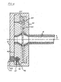
- Fig. 5 is a side view of an alternative exemplary embodiment of the stator with actuators for use with a refining system in accordance with the invention
- Fig. 6 is a schematic diagram of the relationship between sensors and actuators controlling the refining gap according to the invention.
- Fig. 7 is a schematic view of a second exemplary embodiment of the refining system in accordance with the invention.
- Fig. 1 shows generally an exemplary embodiment of a dual disc refiner system 10 designed for preferred application in the refining of paper and pulp slurries according to the invention.
- the refiner 10 incorporates some of the principles and advantages as described in Egan et al. U.S. Patent 5,947,394, issued September 7, 1999 ; and in Egan et al. International Publication No. WO 99/52197, published October 14, 1999 . Also, familiarity with paper pulp refiners, including radially positioned disk-type refiner plates with bar and groove patterns, is assumed.
- the system 10 is comprised of a mounting base 12 having bearing mounts 14,16 supporting a drive shaft 18.
- the drive shaft 18 is rotatably driven by a motor 20 at one end of the drive shaft 18.
- the drive shaft 18 extends along a longitudinal axis a from one end, whereat the motor 20 is provided, to a second end, whereat a refining compartment 30 is provided.
- the refining compartment 30 is comprised of a pivotable stator door 40 housing a stator 42 fixed therein, and a rotor chamber 50 housing a rotor 52 opposite the stator door 40.
- the refining compartment is thus formed by the stator door 40 and the rotor chamber 50 as the stator door 40 is in its closed position.
- the rotor 52 provided in the rotor chamber 50, and the stator 42 provided in the stator door 40 thus oppose one another in close proximity when the stator door 40 is closed.
- the distance between the stator 42 and rotor 52 in the refining compartment 30 when the stator door 40 is closed is the refining gap 60, which may vary as the refining system is used.
- the drive shaft 18 extends longitudinally through a central hub of the rotor 52 and stator 42 when the stator door 40 is closed.
- seals 80 surround the drive shaft 18 at those central hub portions of the stator 42 and rotor 52 so as to cushion vibrations of the drive shaft 18 and to permit small axial and angular movements of the stator 42 or rotor 52 as appropriate during operation of the refiner system 10.
- motors or actuators other than those described herein, is within the scope of the invention.
- the stator 42 may be comprised of several sectors 44, for example, to accommodate easier and less expensive maintenance or replacement of individual sectors 44 of the stator 42 as needed.
- the rotor 52 is similarly comprised of several sectors 54, for example, to also accommodate easier and less expensive maintenance or replacement of the sectors 54 of the rotor 52 as needed.
- Each sector 44, 54 is further comprised of refining surfaces such as bar and groove channel patterns, that complement one another to facilitate refining of slurry (not shown) within the refining gap 60 between the stator 42 and rotor 52 when the stator door 40 is closed.
- the bar and groove channel patterns on the stator 42 and rotor 52 may graduate from larger channels at the inner diameter at the center of the stator 42 and rotor 52, to smaller channels as the patterns extend away from the center to a perimeter of the stator 42, or rotor 52.
- the bar and groove channel patterns thus help to induce the flow of refined slurry to exit the refinement compartment 30.
- the refining compartment 30 thus includes a slurry inlet 70 to introduce slurry to the refining gap 60 region between the stator 42 and rotor 52, and a slurry outlet 72 to discharge the refined slurry from the refining compartment 30 at a perimeter of the chamber 50.
- the slurry inlet 70 generally introduces slurry to a central hub portion of the rotor 52 near the second end of the drive shaft 18.
- the slurry inlet 70 and slurry outlet 72 may vary in size according to the flow requirements of a particular operation by inserting or removing portable fittings (not shown) to/from the slurry inlet 70 and slurry outlet 72 as desired.
- Fig. 2 illustrates one exemplary embodiment of the stator door 40 according to the refiner system described in Fig. 1 .
- the exemplary stator door 40 of Fig. 2 includes three or more actuators 100 detachably mounted to the stator door 40, wherein the movable, or actuatable, portion of each actuator 100 is recessed into the cavity of the stator door 40. Projecting from the exposed portion of each actuator 100 is a threaded eye 102.
- FIG. 3 illustrates the stator 42 mounted to the threaded eye 102 of each actuator 100 of the exemplary stator door 40 shown in Fig. 2 .
- the stator 42 is thus attached to each actuator 100 by screws 46 driven through a threaded bore 47 on an outer band 48 of the stator 42.
- the stator 42 is attached to the threaded eye 102 at one end of each actuator 100, and another end of each actuator 100 is attached to a corresponding recess in the stator door 40.
- Attachment of the stator 42 to the actuators 100 in this manner permits the actuators 100 to move the stator 42 in three degrees of motion independently of one another and in response to changing refining gap 60 distance conditions, or to varying pressure or temperature conditions between various the sectors 44, 54 of the stator 42 and rotor 52, respectively.
- Fig. 4 illustrates an alternative embodiment of the exemplary preferred actuators 100 of Fig. 3 .
- the actuators 100 each include rams 110 (only one shown in Fig. 2 ) of the actuator 100 coupled to the stator 42 and stator door 40.
- each of the actuators 100 are attached to the stator via the threaded eye 102 through which screw 46 is inserted, whereas the rams 110 of each actuator are attached to the stator door 40 using demountable fasteners to facilitate the removal, replacement or servicing of each actuator 100.
- the manner in which the actuators 100 are coupled to the stator is not critical to the present invention.
- pivotable or universal couplings to mount the actuators 100 to the stator door 40 and stator 42 in order to permit the stator 42 to pivot about axes (not shown) transverse to the axis a as the actuators 100 are operated independently of one another.
- the stator 42 also mounts three or more distance sensors 120 (only one shown in Fig. 4 ) for measuring the local axial width of the refining gap 60.
- the rotor 52 preferably mounts a plurality of sensible elements or recesses 122 to provide targets to assist the distance sensors 120 in measuring the local width of the gap 60.
- the distance sensors 120 are electrical sensors symmetrically arranged with respect to the axis a so as to provide information regarding both the overall width of the refining gap 60, and the trim, or angular orientation, of the refining elements, i.e., stator 42 and rotor 52, relative to one another. Examples of such sensors are described in Dodson-Edgars U.S. Patent 4,820,980 .
- distance sensors 120 used is not critical to the present invention.
- Potentially useful sensor types include electrical or magnetic induction sensors and ultrasonic sensors (in conjunction with sensible elements 122 composed of material having suitable electromagnetic or acoustic properties).
- Other suitable types of sensors will be apparent to those of ordinary skill in the art without departing from the scope of the present invention.
- Fig. 5 shows yet another alternative form of a stator assembly 200 in accordance with the present invention.
- the stator assembly 200 includes an end plate 241 mountable to the stator door (not shown in Fig. 5 ) and a stator plate 242 supported by the end plate 241.
- the end plate 241 is mountable to the stator door via a central hub portion 210 having bolt holes 211 through which bolts may be inserted to secure the stator end plate 241 to the stator door.
- the stator end plate 241 mounts three or more actuators 250.
- Each of the actuators 250 preferably is an electric motor including a drive shaft 251 for transmitting rotary or pivotal motion.
- the stator assembly 200 includes a plurality of transmissions 260 associated with the actuators 250.
- the preferred transmissions 260 each include gears 262 mounted on the drive shafts of the actuators 250; mating gears 2644 mounted on the stator end plate 241 so as to convert rotary or pivotal motion about axes (not shown) transverse to the axis a into rotary or pivotal motion about axes (not shown) parallel to the axis a; and rams 266 in meshing or threaded engagement with the mating gears 264 to convert rotary or pivotal motion about the axes (not shown) parallel to the axis a into translation parallel to the axis a.
- the rams 266 preferably are coupled to the stator plate 242 in the same manner in which the rams 110 ( Fig.
- the preferred actuators 250 preferably communicate with a controller (not shown) to permit independent operation of the actuators 250 to adjust the position and trim of the stator plate 242.
- the stator assembly 200 of Fig. 5 further includes an inlet pipe 280 which defines an inlet passage 284 which extends through the stator plate 242.
- the inlet passage 284 provides a path for introducing stock suspension or slurry (not shown) into a refining gap (not shown) between the stator plate 242 and a rotor plate (not shown) to permit refining of the stock suspension slurry (not shown) in the manner described earlier.
- the three or more distance sensors 120 communicate with a controller 130.
- the preferred controller 130 is an electrical or electronic controller, or encoder, including a microprocessor 132 programmed to automatically operating the actuators 100 in response to signals received from the sensors 120.
- the programming of the microprocessor 132 to perform this function is within the ordinary skill in the art and would require no undue experimentation to implement.
- the distance sensors 120 generate signals related to the local axial width of the refining gap 60 at different positions along the refining surface of the stator 42 and rotor 52.
- the microprocessor 132 averages these local axial widths to determine the overall width of the refining gap 60 and compares these local axial widths with one another to determine the trim, or angular orientation, of the stator 42 relative to the rotor 52. This information is either communicated to an operator (not shown) by the preferred controller 130 ( Fig. 6 ) or used within the controller 130 ( Fig. 3 ) to operate the actuators 100 in response to the signals.
- the electronic controller 130 independently energizes the actuators 100 to adjust the overall width of the refining gap 60 as well as the trim, or angular orientation, of the stator 42 relative to the rotor 52.
- the microprocessor 132 Fig. 3
- the preferred microprocessor 132 also compares the digitized values of the signals received from the sensors 120 with reference values to determine the degree to which the stator 42 is out of trim with rotor 52.
- Coordinated energization of the actuators 100 tends to correct errors in the overall width of the refining gap 60.
- Energizing one of the actuators 100 independently of the others causes one portion of the stator 42 to move axially relative to other portions of the stator 42. Since the preferred stator 42 is rigid, this causes the stator 42 to pivot about an axis (not shown) transverse to the axis a, thereby correcting misalignment between the stator 42 and rotor 52. In this manner, the preferred apparatus permits automatic adjustment of the overall refining gap 60 and of the trim, or angular orientation, of the stator 42 and rotor 52.
- controller 130 Fig. 3
- switches not shown
- Such manual adjustment may be performed either in response to visual observations of an operator (not shown) or in response to a readout (not shown) of information derived from signals generated by the distance sensors 130.
- Fig. 7 shows another alternative embodiment of the invention, wherein actuators 300 are similarly mounted to the stator 42 as in Figs. 2-4 , but are responsive to rotary encoders 320, or other similar technology, rather than distance sensors 120 as in Fig. 4 .
- the actuators 300 in this exemplary embodiment are comprised of a preloaded ball nut 310 adjacent precision threads 312.
- the encoder 320 counts the revolutions of motor 330, that drives the preloaded ball nut 310 accordingly.
- a brake 340 is available when the encoder 320 determines that the motor 330 has driven the ball nut 310 to a desired position via precision threads 312.
- the refining gap 60 is initialized to a desired gap value prior to the occurrence of a first refining process. Thereafter, as the refining process occurs, the rotary encoder 320 ( Fig. 7 ) tracks the forward and backward revolutions of the motor, or the sensors 120 ( Figs. 1-6 ) compares current pressure, temperature or distance conditions between the stator and rotor to determine the refining gap change relative to the initialized gap value. If necessary, the refining gap 60 may be re-initialized manually or automatically, as desired, should the change in the refining gap be beyond acceptable limits. Numerous refining processes may occur before re-initialization is needed.
- Such re-initialization can therefore occur in response to predictable wear on the refining elements due to the number of revolutions of the motor, for example, or due to other pressure and/or temperature conditions experienced during the refining processes.
- plate wear and system errors can be compensated for, and better refining element alignment can be achieved.
- similar advantages are possible to be achieved using the sensor 100 and actuators herein described to adjust the refining gap 60 as well.
- the preferred embodiments of the present invention can be used either as original equipment components in newly-manufactured refining systems or as retrofits to existing systems.
- One advantage of the present invention is that it permits adjustment of both the overall width of the refining gap 60 as well as adjustment of the trim, or angular orientation, of the stator 42 relative to the rotor 52. In this manner, it allows operators to correct misalignments occurring during assembly of the refiner system 10, and to correct misalignments resulting from operation of the refiner system 10, such as those which might result from uneven wear of the sectors 44, 54 of the stator 42 or rotor 52.
- Optimizing the local axial width of the refining gap 60 along the entire refining surfaces of the stator 42 and rotor 52, and not merely the overall width of the refining gap 60, will tend to improve the efficiency of the refining system 10 and to increase the useful lives of the stator 42 and rotor 52.
- Another advantage of the present invention is that it provides such adjustments automatically. It is within the contemplation of the invention to provide such adjustments while the refining system 10 is filled with fluid or even as the system 10 is operating.
Abstract
Description
- This application claims the priority benefit of
U.S. Provisional Patent Application Serial No. 60/477,014 filed June 9, 2003 - This invention relates to an improved mechanical refiner. More particularly, it relates to an improvement to a mechanical refiner having a stator mounting a first refining element and a rotor mounting a second refining element spaced from said first refining element to define a refining gap. The refining gap and alignment of the trim, or angular orientation, of the refining elements relative to one another are actively maintained according to various conditions of the refining elements or the number of motor revolutions even as the refiner is in use. Actuators are coupled to the stator and a controller to adjust the average or overall width of the refining gap and the trim, or angular orientation, of the stator relative to the rotor, thus providing three or more degrees of control over the spacing between the stator and the rotor.
- Cellulosic fibers such as paper pulp, bagasse, insulation or fiber board materials, cotton and the like, are commonly subjected to a refining operation which consists of mechanically rubbing the fibers between sets of relatively rotating bar and groove elements. In a disk-type refiner, for example, these elements commonly consist of plates having annularly arranged bar and groove patterns defining their working surfaces, with the bars and grooves extending generally radially of an axis of the rotating element, or more often at an angle oblique to a radius to the center of the annular pattern, so that the stock can work its way from the center of the pattern to its outer periphery.
- Disk-refiners are commonly manufactured in both single and twin disk types. In a single disk refiner, the working surface of the rotor comprises an annular refiner plate, or a set of segmental refiner plates, for cooperative working action with a complementary working surface on the stator, which also comprises an annular plate or a series of segmental plates forming an annulus. In a twin disk refiner, the rotor is provided with working surfaces on both sides. The working surfaces of the rotor cooperate with a pair of opposed complementary working surfaces on the stator, with these working surfaces being generally of the same type of construction as with a single disk refiner.
- Paper pulp refiners as described, including the plug or cone type refiners, require the control of the position and axial spacing of the relatively rotating members for the purpose of controlling refiner load and for controlling the quality of the refined paper fiber product, among other reasons. A plug type refiner is shown in
Staege et al., U.S. Patent 2,666,368 , while a control arrangement for a dual inlet disk type refiner is shown in HaywardU.S. Patent 3,506,199 . - Known refiners have included mechanical drive systems for moving one refining element closer or farther from the other along the axis of rotation of the rotor. It also is known to provide electrical or electronic controllers, such as that shown in Hayward, to control the axial spacing of the refining elements in response to motor load, changing voltage or power factors, or pulp quality. Reference may be had to Baxter
U.S. Patent 2,986,434 , which shows a dual inlet radial disk type refiner and the reduction gearing through which the axial position of the stator and rotor elements may be accurately determined and maintained.WO99/52197 - Mechanical refining is optimized when the gap between the refining elements of the stator and rotor is on the order of 0.001 inch to 0.010 inch (0.025 mm to 0.25 mm). The actual spacing of the stator and rotor plates is dependent upon numerous stack-up items in the assembly of the refiner. Due to typical manufacturing tolerances, the design misalignment can be as much as 0.045 inch (1.1 mm).
- One drawback to known refining systems is that they make no provision for correcting errors in the trim, or angular orientation, of the refining elements relative to one another. Thus, when the stator plate is inclined relative to the rotor plate, for example, certain portions of the refining surface of the refining element mounted by the stator plate will be closer to the complementary surface of the refining element mounted by the rotor than other portions of the refining surface. This implies a variation in the width of the refining gap between the refining elements along the surfaces of the refining elements even when the average or overall refining gap is optimized.
-
Dodson-Edgars U.S. Patent 4,820,980 shows an apparatus and method for measuring the gap, tram, deflection and wear of rotating grinding plates such as those found in mechanical refiners. In particular, Dodson-Edgars shows inductive sensors mounted in a recessed manner inset from the surface of a first grinding plate and located opposite recessed non-wear surfaces of a second grinding plate. The sensors are monitored by a microprocessor system, which processes signals from the sensors to determine gap, tram, deflection and wear. Dodson-Edgars teaches that plate tram may be controlled by angular displacement of the drive shaft which drives one of the rotating plates or by angular displacement of the other, stationary plate, but does not disclose any apparatus for carrying out such an adjustment. - Thus, there remains a need in the art for an improved mechanical refining system providing control, preferably automatic control, of the trim of the refining elements mounted by the stator and rotor relative to one another, as well as providing automatic control of the average or overall refining gap between the elements.
- This need and others are addressed by a mechanical refiner system which permits adjustment of the overall, or average, gap between the refining elements and of the trim, or angular orientation, of the refining elements relative to one another. The preferred apparatus is a mechanical refiner system including three or more actuators, for example, coupled to the stator, and a controller in communication with those actuators for independently operating the actuators to adjust the average, or overall, axial width of the refining gap as well as to adjust the trim, or angular orientation, of the refining elements relative to one another.
- The preferred apparatus of the present invention provides an improved degree of control over the separation of the refining elements of a mechanical refining system. It permits an operator to adjust the average, or overall, refining gap and to correct misalignments of the refining elements immediately after assembly and/or as the refining elements wear in the course of service. In this manner, the operator can improve the performance of the mechanical refining system throughout the useful lives of the refining elements.
- In accordance with an especially preferred embodiment, the apparatus comprises an end plate; a stator including a refining element; and three or more actuators coupled to the stator for controlling the position and orientation of the stator relative to the rotor. In accordance with this embodiment, the preferred mechanical refiner includes a casing defining a refiner compartment having an open end. The end plate closes the open end of the refiner compartment and supports the actuators, which actuators adjust the spacing and relative angular orientation of the stator and the rotor. The nature of the three or more actuators is not critical to the invention, although preferred actuators include electric motors, hydraulic motors and pneumatic motors. Most preferably, the three or more actuators are electric motors and the controller is an electronic controller, or encoder, programmed to independently operate the actuators to adjust both the overall axial width of the refining gap and the relative trim, or angular orientation, of the refining elements.
- In accordance with another especially preferred embodiment, at least one of the actuators has a ram extending substantially in parallel with the axis about which the rotor rotates so as to provide adjustment of the refining gap. In accordance with yet another especially preferred embodiment, at least one of the actuators has a drive shaft extending transversely to the axis. Such apparatus preferably includes a transmission connected between the actuators and the stator for converting rotary power from the actuators into axial translation of the stator relative to the rotor.
- In accordance with still another preferred embodiment, the apparatus includes at least three distance sensors mounted on the stator for generating a plurality of sensor signals related to the axial width of the refiner gap at different positions on the refining surface of the stator. In accordance with this embodiment, the preferred controller, or encoder, is programmed to compare the sensor signals with one or more reference values, such as initialized values, for example. In addition, the preferred controller, or encoder, is programmed to independently operate the actuators to adjust both the overall width of the refining gap and the trim of the refining elements relative to each other. The structure is capable of providing automatic optimization of the spacing and trim, or angular orientation, of the refining elements throughout the useful lives of those elements, even when the operator of the system is unskilled.
- The preferred apparatus in accordance with the invention is capable of serving either as an original component of a mechanical refining system or as a retrofit to existing equipment. To this end, configurations of the stator housing and the stator plate are not critical to the invention; rather, those skilled in the art will recognize that a wide variety of stator housing and stator plate configurations will be within the scope of the present invention depending on the specifications of the system in which the apparatus is to be used.
- Another aspect of the present invention involves a method for refining a slurry using a mechanical refiner having an inlet for receiving the slurry to be refined, a discharge outlet for refined slurry, a stator mounting a first refining element defining a refining surface, and a rotor mounting a second refining element facing the refining surface to define a refining gap in communication with the inlet and the discharge outlet. A preferred method in accordance with the invention comprises the steps of comparing the local axial width of the refining gap at three or more positions along said refining surface with one or more reference values, such as initialized gap values, for example; independently moving three or more portions on the stator along the axis to adjust both the axial width of the refining gap and the trim, or angular orientation, of the first refining element relative to the second refining element; inducing the slurry to flow through the inlet into the refining gap; and turning the rotor about the axis and relative to the stator to refine the slurry in the refining gap. Most preferably, the independent movement of the three or more portions of the stator along the axis is effected by three or more actuators acting under the influence of sensor signals generated by distance sensors.
- Therefore, it is one object of the present invention to provide better control over the overall refining gap and relative the trim, or angular orientation, of the refining elements. It is another object of the invention to provide such control automatically. These and other objects and advantages of the invention will be apparent from the following description, the accompanying drawing and the appended claims.
-
Fig. 1 is perspective view of an exemplary embodiment of a refining system in accordance with the invention; -
Fig. 2 is a partial side view of an exemplary stator door with actuators in the refining system ofFig. 1 ; -
Fig. 3 is a side view of the stator mounted to the stator door ofFig. 2 ; -
Fig. 4 is an alternative embodiment of the actuators of the refining system ofFig. 3 ; -
Fig. 5 is a side view of an alternative exemplary embodiment of the stator with actuators for use with a refining system in accordance with the invention; -
Fig. 6 is a schematic diagram of the relationship between sensors and actuators controlling the refining gap according to the invention; and -
Fig. 7 is a schematic view of a second exemplary embodiment of the refining system in accordance with the invention. - Preferred exemplary embodiments of an exemplary dual disc type refining system with actuator controlled positioning of a refining gap will be described herein with reference to
Figs. 1-6 . Those of ordinary skill in the art will recognize that the various exemplary embodiments of the invention described herein can be adopted to other conventional forms of refining equipment without undue experimentation. -
Fig. 1 shows generally an exemplary embodiment of a dualdisc refiner system 10 designed for preferred application in the refining of paper and pulp slurries according to the invention. Therefiner 10 incorporates some of the principles and advantages as described inEgan et al. U.S. Patent 5,947,394, issued September 7, 1999 ; and in Egan et al. International Publication No.WO 99/52197, published October 14, 1999
Also, familiarity with paper pulp refiners, including radially positioned disk-type refiner plates with bar and groove patterns, is assumed. - The
system 10 is comprised of a mountingbase 12 having bearing mounts 14,16 supporting adrive shaft 18. Thedrive shaft 18 is rotatably driven by amotor 20 at one end of thedrive shaft 18. Thedrive shaft 18 extends along a longitudinal axis a from one end, whereat themotor 20 is provided, to a second end, whereat arefining compartment 30 is provided. Therefining compartment 30 is comprised of apivotable stator door 40 housing astator 42 fixed therein, and arotor chamber 50 housing arotor 52 opposite thestator door 40. The refining compartment is thus formed by thestator door 40 and therotor chamber 50 as thestator door 40 is in its closed position. Therotor 52 provided in therotor chamber 50, and thestator 42 provided in thestator door 40 thus oppose one another in close proximity when thestator door 40 is closed. The distance between thestator 42 androtor 52 in therefining compartment 30 when thestator door 40 is closed is therefining gap 60, which may vary as the refining system is used. - The
drive shaft 18 extends longitudinally through a central hub of therotor 52 andstator 42 when thestator door 40 is closed. Most preferably, seals 80 surround thedrive shaft 18 at those central hub portions of thestator 42 androtor 52 so as to cushion vibrations of thedrive shaft 18 and to permit small axial and angular movements of thestator 42 orrotor 52 as appropriate during operation of therefiner system 10. Of course, those skilled in the art will recognize that the use of various forms of motors or actuators, other than those described herein, is within the scope of the invention. - The
stator 42 may be comprised ofseveral sectors 44, for example, to accommodate easier and less expensive maintenance or replacement ofindividual sectors 44 of thestator 42 as needed. Therotor 52 is similarly comprised ofseveral sectors 54, for example, to also accommodate easier and less expensive maintenance or replacement of thesectors 54 of therotor 52 as needed. Eachsector refining gap 60 between thestator 42 androtor 52 when thestator door 40 is closed. The bar and groove channel patterns on thestator 42 androtor 52 may graduate from larger channels at the inner diameter at the center of thestator 42 androtor 52, to smaller channels as the patterns extend away from the center to a perimeter of thestator 42, orrotor 52. The bar and groove channel patterns thus help to induce the flow of refined slurry to exit therefinement compartment 30. - The
refining compartment 30 thus includes a slurry inlet 70 to introduce slurry to therefining gap 60 region between thestator 42 androtor 52, and a slurry outlet 72 to discharge the refined slurry from therefining compartment 30 at a perimeter of thechamber 50. The slurry inlet 70 generally introduces slurry to a central hub portion of therotor 52 near the second end of thedrive shaft 18. The slurry inlet 70 and slurry outlet 72 may vary in size according to the flow requirements of a particular operation by inserting or removing portable fittings (not shown) to/from the slurry inlet 70 and slurry outlet 72 as desired. -
Fig. 2 illustrates one exemplary embodiment of thestator door 40 according to the refiner system described inFig. 1 . Theexemplary stator door 40 ofFig. 2 includes three ormore actuators 100 detachably mounted to thestator door 40, wherein the movable, or actuatable, portion of each actuator 100 is recessed into the cavity of thestator door 40. Projecting from the exposed portion of each actuator 100 is a threadedeye 102. -
Fig. 3 illustrates thestator 42 mounted to the threadedeye 102 of eachactuator 100 of theexemplary stator door 40 shown inFig. 2 . As shown inFig. 3 andFig. 4 , thestator 42 is thus attached to each actuator 100 byscrews 46 driven through a threadedbore 47 on anouter band 48 of thestator 42. Thus, thestator 42 is attached to the threadedeye 102 at one end of each actuator 100, and another end of each actuator 100 is attached to a corresponding recess in thestator door 40. Attachment of thestator 42 to theactuators 100 in this manner permits theactuators 100 to move thestator 42 in three degrees of motion independently of one another and in response to changingrefining gap 60 distance conditions, or to varying pressure or temperature conditions between various thesectors stator 42 androtor 52, respectively. -
Fig. 4 illustrates an alternative embodiment of the exemplarypreferred actuators 100 ofFig. 3 . As shown inFig. 4 , theactuators 100 each include rams 110 (only one shown inFig. 2 ) of theactuator 100 coupled to thestator 42 andstator door 40. In the embodiment shown inFig. 4 , each of theactuators 100 are attached to the stator via the threadedeye 102 through which screw 46 is inserted, whereas therams 110 of each actuator are attached to thestator door 40 using demountable fasteners to facilitate the removal, replacement or servicing of eachactuator 100. Those skilled in the art will recognize that the manner in which theactuators 100 are coupled to the stator is not critical to the present invention. It is within the contemplation of the invention to use pivotable or universal couplings to mount theactuators 100 to thestator door 40 andstator 42 in order to permit thestator 42 to pivot about axes (not shown) transverse to the axis a as theactuators 100 are operated independently of one another. - As also shown in
Fig. 4 , and in accordance with one exemplary embodiment, thestator 42 also mounts three or more distance sensors 120 (only one shown inFig. 4 ) for measuring the local axial width of therefining gap 60. Therotor 52 preferably mounts a plurality of sensible elements orrecesses 122 to provide targets to assist thedistance sensors 120 in measuring the local width of thegap 60. Most preferably, thedistance sensors 120 are electrical sensors symmetrically arranged with respect to the axis a so as to provide information regarding both the overall width of therefining gap 60, and the trim, or angular orientation, of the refining elements, i.e.,stator 42 androtor 52, relative to one another. Examples of such sensors are described inDodson-Edgars U.S. Patent 4,820,980 . - One reasonably skilled in the art would appreciate that the type of
distance sensors 120 used is not critical to the present invention. Potentially useful sensor types include electrical or magnetic induction sensors and ultrasonic sensors (in conjunction withsensible elements 122 composed of material having suitable electromagnetic or acoustic properties). Other suitable types of sensors will be apparent to those of ordinary skill in the art without departing from the scope of the present invention. -
Fig. 5 shows yet another alternative form of astator assembly 200 in accordance with the present invention. Thestator assembly 200 includes anend plate 241 mountable to the stator door (not shown inFig. 5 ) and astator plate 242 supported by theend plate 241. Theend plate 241 is mountable to the stator door via a central hub portion 210 having bolt holes 211 through which bolts may be inserted to secure thestator end plate 241 to the stator door. Thestator end plate 241, in addition, mounts three ormore actuators 250. Each of theactuators 250 preferably is an electric motor including a drive shaft 251 for transmitting rotary or pivotal motion. In addition, thestator assembly 200 includes a plurality oftransmissions 260 associated with theactuators 250. - The
preferred transmissions 260 each include gears 262 mounted on the drive shafts of theactuators 250; mating gears 2644 mounted on thestator end plate 241 so as to convert rotary or pivotal motion about axes (not shown) transverse to the axis a into rotary or pivotal motion about axes (not shown) parallel to the axis a; and rams 266 in meshing or threaded engagement with the mating gears 264 to convert rotary or pivotal motion about the axes (not shown) parallel to the axis a into translation parallel to the axis a. Therams 266 preferably are coupled to thestator plate 242 in the same manner in which the rams 110 (Fig. 4 ) were coupled to the stator plate 42 (Fig. 4 ) of the earlier embodiment, although the manner of such coupling is not critical to the present invention. Thepreferred actuators 250 preferably communicate with a controller (not shown) to permit independent operation of theactuators 250 to adjust the position and trim of thestator plate 242. - The
stator assembly 200 ofFig. 5 further includes an inlet pipe 280 which defines aninlet passage 284 which extends through thestator plate 242. Theinlet passage 284 provides a path for introducing stock suspension or slurry (not shown) into a refining gap (not shown) between thestator plate 242 and a rotor plate (not shown) to permit refining of the stock suspension slurry (not shown) in the manner described earlier. - With reference to
Fig. 6 , the three or more distance sensors 120 (only three shown inFig. 6 ) communicate with acontroller 130. Thepreferred controller 130 is an electrical or electronic controller, or encoder, including amicroprocessor 132 programmed to automatically operating theactuators 100 in response to signals received from thesensors 120. The programming of themicroprocessor 132 to perform this function is within the ordinary skill in the art and would require no undue experimentation to implement. - In accordance with an exemplary mode of operation, and with reference to
Fig. 4 , thedistance sensors 120 generate signals related to the local axial width of therefining gap 60 at different positions along the refining surface of thestator 42 androtor 52. Themicroprocessor 132 averages these local axial widths to determine the overall width of therefining gap 60 and compares these local axial widths with one another to determine the trim, or angular orientation, of thestator 42 relative to therotor 52. This information is either communicated to an operator (not shown) by the preferred controller 130 (Fig. 6 ) or used within the controller 130 (Fig. 3 ) to operate theactuators 100 in response to the signals. - More preferably, the electronic controller 130 (
Fig. 6 ) independently energizes theactuators 100 to adjust the overall width of therefining gap 60 as well as the trim, or angular orientation, of thestator 42 relative to therotor 52. More specifically, the microprocessor 132 (Fig. 3 ) digitizes the signals (not shown) received from thesensors 120, averages the digitized values of those signals and compares the average with a reference value to determine the degree to which the overall width of therefining gap 60 differs from a desired width or range of width. The preferred microprocessor 132 (Fig. 6 ) also compares the digitized values of the signals received from thesensors 120 with reference values to determine the degree to which thestator 42 is out of trim withrotor 52. - Coordinated energization of the
actuators 100 tends to correct errors in the overall width of therefining gap 60. Energizing one of theactuators 100 independently of the others causes one portion of thestator 42 to move axially relative to other portions of thestator 42. Since thepreferred stator 42 is rigid, this causes thestator 42 to pivot about an axis (not shown) transverse to the axis a, thereby correcting misalignment between thestator 42 androtor 52. In this manner, the preferred apparatus permits automatic adjustment of theoverall refining gap 60 and of the trim, or angular orientation, of thestator 42 androtor 52. - Alternatively, it is within the scope of the invention to provide the controller 130 (
Fig. 3 ) with switches (not shown) to permit manual adjustment of the overall width of therefining gap 60 and of the trim of thestator 42 relative totherotor 52. Such manual adjustment may be performed either in response to visual observations of an operator (not shown) or in response to a readout (not shown) of information derived from signals generated by thedistance sensors 130. -
Fig. 7 shows another alternative embodiment of the invention, wherein actuators 300 are similarly mounted to thestator 42 as inFigs. 2-4 , but are responsive torotary encoders 320, or other similar technology, rather thandistance sensors 120 as inFig. 4 . The actuators 300 in this exemplary embodiment are comprised of apreloaded ball nut 310adjacent precision threads 312. Theencoder 320 counts the revolutions of motor 330, that drives thepreloaded ball nut 310 accordingly. A brake 340 is available when theencoder 320 determines that the motor 330 has driven theball nut 310 to a desired position viaprecision threads 312. - Thus, in all of the exemplary embodiments described with reference to
Figs. 1-7 , therefining gap 60 is initialized to a desired gap value prior to the occurrence of a first refining process. Thereafter, as the refining process occurs, the rotary encoder 320 (Fig. 7 ) tracks the forward and backward revolutions of the motor, or the sensors 120 (Figs. 1-6 ) compares current pressure, temperature or distance conditions between the stator and rotor to determine the refining gap change relative to the initialized gap value. If necessary, therefining gap 60 may be re-initialized manually or automatically, as desired, should the change in the refining gap be beyond acceptable limits. Numerous refining processes may occur before re-initialization is needed. Such re-initialization can therefore occur in response to predictable wear on the refining elements due to the number of revolutions of the motor, for example, or due to other pressure and/or temperature conditions experienced during the refining processes. Thus, by actively engaging in a strategic re-initialization schedule based on initialized gap values and ongoing processing conditions, plate wear and system errors can be compensated for, and better refining element alignment can be achieved. Of course, it should be appreciated that similar advantages are possible to be achieved using thesensor 100 and actuators herein described to adjust therefining gap 60 as well. - The preferred embodiments of the present invention can be used either as original equipment components in newly-manufactured refining systems or as retrofits to existing systems. One advantage of the present invention is that it permits adjustment of both the overall width of the
refining gap 60 as well as adjustment of the trim, or angular orientation, of thestator 42 relative to therotor 52. In this manner, it allows operators to correct misalignments occurring during assembly of therefiner system 10, and to correct misalignments resulting from operation of therefiner system 10, such as those which might result from uneven wear of thesectors stator 42 orrotor 52. Optimizing the local axial width of therefining gap 60 along the entire refining surfaces of thestator 42 androtor 52, and not merely the overall width of therefining gap 60, will tend to improve the efficiency of therefining system 10 and to increase the useful lives of thestator 42 androtor 52. - Another advantage of the present invention is that it provides such adjustments automatically. It is within the contemplation of the invention to provide such adjustments while the
refining system 10 is filled with fluid or even as thesystem 10 is operating. - While the method and form of apparatus herein described constitutes a preferred embodiment of this invention, it is to be understood that the invention is not limited to this precise method and form of apparatus, and that changes may be made therein without departing from the scope of the invention which is defined in the appended claims.
Claims (20)
- A mechanical refiner (10) having an inlet (70) for receiving a slurry to be refined, a discharge outlet (72) for refined slurry, a stator (42) mounting a first refining element, and a rotor (52) mounting a second refining element spaced from said first refining element to define a refining gap (60) in communication with said inlet (70) and said discharge outlet (72), said rotor (52) being supported for rotary movement about an axis and relative to said stator (42) for refining said slurry in said refining gap (60); the refiner characterised by
three or more actuators (100) coupled to said stator (42); and
a controller (130) in communication with said three or more actuators (100) for independently operating said three or more actuators (100) to adjust an axial width of said refining gap (60) and to adjust a trim of said first refining element relative to said second refining element. - A mechanical refiner (10) as recited in claim 1 wherein said mechanical refiner (10) includes a casing defining a refining compartment (30) having an open end and an end plate (241) closing said open end so as to enclose said first and second refining elements in said refining compartment (30), said end plate (241) mounting said three or more actuators (250).
- A mechanical refiner (10) as recited in claim 1 wherein said three or more actuators (100) are arranged symmetrically about the axis.
- A mechanical refiner (10) as recited in claim 1 or claim 2 including a transmission (260) connected to said stator (42) for converting rotary power into axial extension, wherein at least one of said three or more actuators (250) has a drive shaft (251) coupled to said transmission (260) for supplying rotary power to said transmission (261) and inducing axial movement of a portion of said stator (42).
- A mechanical refiner (10) as recited in any foregoing claim wherein said controller (130) is an electronic controller programmed to independently operate said three or more actuators (100) to adjust the axial width of said refining gap (60) and to adjust the trim of said first refining element relative to said second refining element.
- Apparatus for use in a mechanical refiner (10) comprising:an end plate (241);a stator (42) including a refining element, said refining element defining an axis; characterised bythree or more actuators (250) supported by said end plate and coupled to said stator (42) for controlling an axial position and trim of said refining element.
- The apparatus as recited in claim 6 wherein said three or more actuators (250) are arranged symmetrically about the axis.
- The apparatus as recited in claim 6 or claim 7 wherein at least one of said three or more actuators (250) includes a motor (330) selected from the group consisting of an electric motor, a hydraulic motor and a pneumatic motor.
- The apparatus as recited in any of claims 6 to 8 wherein at least one of said three or more actuators (100) has a ram (110) extending substantially in parallel with the axis.
- The apparatus as recited in any of claims 6 to 9 wherein at least one of said three or more actuators (250) has a drive shaft (251) extending transversely to the axis.
- The apparatus as recited in any of claims 6 to 10 including a transmission (260) connected to said stator (42) for converting rotary power into axial extension, wherein at least one of said three or more actuators (250) has a drive shaft (251) coupled to said transmission (260) for supplying rotary power to said transmission (260) and inducing axial movement of a portion of said stator (42).
- The apparatus as recited in any of claims 6 to 11 wherein said controller (130) is an electronic controller programmed to independently operate said three or more actuators (100) to adjust the axial width of said refining gap (60) and to adjust the trim of said first refining element.
- The apparatus as recited in any of claims 6 to 12 including at least three sensors (120) mounted on said stator (42) for generating a plurality of sensor signals, wherein said controller (130) is an electronic controller programmed to compare said plurality of sensor signals with one or more reference values, and to independently operate said three or more actuators (250) to adjust the axial position and trim of said first refining element.
- The apparatus as recited in claim 13, wherein the signals generated are one of distance, pressure and temperature conditions representing refining gap (60) and processing conditions.
- A mechanical refiner as recited in any of claims 1 to 5, wherein the actuators (330) are further comprised of a ball nut (310) engageable with precision threads (312) in response to an encoded information driven motor (330).
- A mechanical refiner as recited in any of claims 1 to 5 or 15, wherein the controller (130) is an encoder (320) actively adjusting the axial width of said refining gap (60) and said trim according to changing operating conditions.
- A mechanical refiner of claim 16, wherein the operating conditions are at least one of refiner element wear, pressure, temperature and motor revolutions.
- A method for refining a slurry using a mechanical refiner (10) having an inlet (70) for receiving a slurry to be refined, a discharge outlet (72) for refined slurry, a stator (42) mounting a first refining element, and a rotor (52) mounting a second refining element spaced from said first refining element to define a refining gap (60) in communication with said inlet (70) and said discharge outlet (72), said rotor (52) being supported for rotary movement about an axis and relative to said stator (42) for refining said slurry in said refining gap (60); said method comprising the steps of:a) initializing the refining gap (60) to zero;b) comparing operating conditions in the mechanical refiner (10) with one or more reference values;c) independently moving three or more spaced portions of the stator (42) along the axis to adjust an axial width of the refining gap (60) and to adjust a trim of the first refining element relative to the second refining element according to operating conditions;d) inducing the slurry to flow through the inlet (70) into the refining gap (60); ande) rotating the rotor (52) about the axis and relative to the stator (42) to refine the slurry in the refining gap (60).
- The method recited in claim 18, wherein the operating conditions are at least one of refiner element wear, pressure, temperature, and motor revolutions.
- The method recited in claim 18 or claim 19, wherein actuators (330) comprising a ball nut (310) engageable with precision threads (312) move the spaced portions of the stator (42) in response to an encoder information driven motor (330).
Applications Claiming Priority (2)
| Application Number | Priority Date | Filing Date | Title |
|---|---|---|---|
| US47701403P | 2003-06-09 | 2003-06-09 | |
| PCT/US2004/018103 WO2004111331A2 (en) | 2003-06-09 | 2004-06-08 | Self-aligning and actively compensating refiner stator plate system |
Publications (3)
| Publication Number | Publication Date |
|---|---|
| EP1631391A2 EP1631391A2 (en) | 2006-03-08 |
| EP1631391A4 EP1631391A4 (en) | 2007-08-01 |
| EP1631391B1 true EP1631391B1 (en) | 2011-01-05 |
Family
ID=33551662
Family Applications (1)
| Application Number | Title | Priority Date | Filing Date |
|---|---|---|---|
| EP04754655A Revoked EP1631391B1 (en) | 2003-06-09 | 2004-06-08 | Self-aligning and actively compensating refiner stator plate system |
Country Status (7)
| Country | Link |
|---|---|
| US (1) | US7694902B2 (en) |
| EP (1) | EP1631391B1 (en) |
| JP (1) | JP4726796B2 (en) |
| CN (1) | CN100566839C (en) |
| CA (1) | CA2528773C (en) |
| DE (1) | DE602004030906D1 (en) |
| WO (1) | WO2004111331A2 (en) |
Families Citing this family (13)
| Publication number | Priority date | Publication date | Assignee | Title |
|---|---|---|---|---|
| US8415354B2 (en) | 2004-04-29 | 2013-04-09 | Abbott Laboratories | Methods of use of inhibitors of the 11-beta-hydroxysteroid dehydrogenase type 1 enzyme |
| DE102005058192A1 (en) * | 2005-12-06 | 2007-06-28 | Airbus Deutschland Gmbh | Device for fault detection of adjustable flaps |
| DE102006022886B4 (en) * | 2006-05-15 | 2020-02-27 | Pallmann Maschinenfabrik Gmbh & Co. Kg | Device for comminuting feed material |
| JP4920496B2 (en) * | 2007-05-29 | 2012-04-18 | 株式会社サトミ製作所 | Refiner rotor moving method and refiner |
| ITVR20070170A1 (en) * | 2007-11-23 | 2009-05-24 | Airaghi Srl Off | PROCEDURE FOR THE REALIZATION OF CONICAL SPARE PARTS FOR REFINERS FOR THE PRODUCTION OF PAPER |
| US20120192954A1 (en) * | 2011-01-31 | 2012-08-02 | Red Lion Bio-Energy Technologies | Rotating disc valve |
| US9457353B2 (en) | 2013-01-31 | 2016-10-04 | Orlando Utilities Commission | Coal pulverizer monitoring system and associated methods |
| US9272285B2 (en) * | 2014-04-29 | 2016-03-01 | Chin-Chu Wu | Emulsification grinder |
| US20190262837A1 (en) * | 2018-02-23 | 2019-08-29 | Orenda Automation Technologies Inc. | Gap adjusting system for a disc mill assembly of a reducing machine |
| CN108745456B (en) * | 2018-07-17 | 2023-08-22 | 中铁工程装备集团有限公司 | Jaw breaker angle monitoring device |
| US11020749B2 (en) * | 2018-09-30 | 2021-06-01 | Northeastern University | Servo control device and method for disc gap in disc powder grinding system |
| FI128873B (en) * | 2019-12-17 | 2021-02-15 | Valmet Technologies Oy | Arrangement and method for adjusting blade gap in refiner |
| EP4050154B1 (en) * | 2021-02-27 | 2023-08-16 | Valmet Technologies, Inc. | Disc refiner sliding head adjustment assembly |
Family Cites Families (29)
| Publication number | Priority date | Publication date | Assignee | Title |
|---|---|---|---|---|
| US2666368A (en) | 1950-10-14 | 1954-01-19 | Black Clawson Co | Paper machinery |
| US2986434A (en) | 1957-02-13 | 1961-05-30 | Black Clawson Co | Paper machinery |
| US3506199A (en) | 1968-01-18 | 1970-04-14 | Black Clawson Co | Paper pulp refiner control system |
| SE327624B (en) | 1968-12-20 | 1970-08-24 | Reinhall Rolf | |
| US3827644A (en) | 1969-02-19 | 1974-08-06 | Defibrator Ab | Grinding apparatus |
| US3799456A (en) * | 1972-06-14 | 1974-03-26 | Bauer Bros Co | Refiner plate clearance control system |
| US3847359A (en) * | 1973-12-14 | 1974-11-12 | Sprout Waldron & Co Inc | Disc type refiner with automatic plate spacing control |
| US4081147A (en) * | 1976-05-27 | 1978-03-28 | The Black Clawson Company | Reversible disk refiner plates |
| US4083503A (en) * | 1976-10-08 | 1978-04-11 | Beloit Corporation | Paper stock rotor axial position controlling and locking device |
| US4253613A (en) | 1978-02-17 | 1981-03-03 | Reinhall Rolf Bertil | Method and apparatus for controlling the effect of the centrifugal force on the stock in pulp defibrating apparatus |
| SE422224B (en) | 1978-08-07 | 1982-02-22 | Berggren Torsten L | MILLING MACHINE FOR TREATMENT OF FIBER SLAMPS, AS PAPER PAPER, AND PIECE OF MALGUDE, SUCH AS TREFLIS AND SPAN |
| US4283016A (en) | 1979-03-16 | 1981-08-11 | Reinhall Rolf Bertil | Method and apparatus for controlling the effect of the centrifugal force on the stock in pulp defibrating apparatus |
| US4275852A (en) * | 1979-08-20 | 1981-06-30 | Asplund Arne J A | Apparatus for controlling the refining of fibrous pulp grist in a drum refiner |
| SE8302013L (en) | 1983-04-12 | 1984-10-13 | Sunds Defibrator | DEVICE FOR MALAPPLANTS FOR REFINING LIGNOCELLULOSALLY MATERIAL |
| JPS62194795A (en) * | 1986-02-21 | 1987-08-27 | Nippon Telegr & Teleph Corp <Ntt> | Time division channel system |
| US4820980A (en) * | 1987-05-04 | 1989-04-11 | Dodson Edgars Darryl | Gap, wear and tram measurement system and method for grinding machines |
| JP2811092B2 (en) * | 1989-09-05 | 1998-10-15 | 相川鉄工株式会社 | Operation method in double disc refiner for papermaking |
| CA2096271A1 (en) | 1993-05-14 | 1994-11-15 | Thomas Arvidsson | Support for a stator of a refining machine |
| US5971307A (en) | 1998-02-13 | 1999-10-26 | Davenport; Ricky W. | Rotary grinder |
| US5445328A (en) | 1993-08-25 | 1995-08-29 | Andritz Sprout-Bauer, Inc. | Dual zone refiner with separated discharge flow control |
| US5813618A (en) | 1995-11-28 | 1998-09-29 | Andritz Sprout-Bauer, Inc. | Continuous cyclindrical wood pulp refiner |
| US5707016A (en) | 1996-07-01 | 1998-01-13 | Witsken; Anthony | Apparatus and methods for wet grinding |
| JP4245272B2 (en) | 1997-10-09 | 2009-03-25 | サーモ・ブラック・クローソン・インコーポレーテッド | Apparatus and method for controlling pulp refining machine for papermaking |
| US5927628A (en) | 1998-03-03 | 1999-07-27 | Dallas A. C. Horn & Co. | Grinding apparatus for foodstuffs |
| CN1099153C (en) * | 1998-04-08 | 2003-01-15 | 塞莫·布莱克·克劳森公司 | Integrated paper pulp and process machinery having integrated drive and control and methods for use thereof |
| US20020070303A1 (en) * | 2000-12-12 | 2002-06-13 | J & L Fiber Services, Inc. | Adjustable refiner plate |
| JP3797909B2 (en) * | 2001-10-16 | 2006-07-19 | 相川鉄工株式会社 | Refiner and paper stirrer |
| FI118971B (en) * | 2002-07-02 | 2008-05-30 | Metso Paper Inc | Refiner |
| SE524792C2 (en) * | 2003-03-24 | 2004-10-05 | Daprox Ab | Method and sensor device for distance measurement between a stator and a rotor opposite to it |
-
2004
- 2004-06-08 EP EP04754655A patent/EP1631391B1/en not_active Revoked
- 2004-06-08 CA CA2528773A patent/CA2528773C/en not_active Expired - Fee Related
- 2004-06-08 WO PCT/US2004/018103 patent/WO2004111331A2/en active Application Filing
- 2004-06-08 JP JP2006533600A patent/JP4726796B2/en not_active Expired - Fee Related
- 2004-06-08 DE DE602004030906T patent/DE602004030906D1/en active Active
- 2004-06-08 CN CNB2004800211435A patent/CN100566839C/en not_active Expired - Fee Related
-
2005
- 2005-06-08 US US10/559,739 patent/US7694902B2/en not_active Expired - Fee Related
Also Published As
| Publication number | Publication date |
|---|---|
| US7694902B2 (en) | 2010-04-13 |
| DE602004030906D1 (en) | 2011-02-17 |
| CA2528773A1 (en) | 2004-12-23 |
| US20060231649A1 (en) | 2006-10-19 |
| EP1631391A2 (en) | 2006-03-08 |
| CA2528773C (en) | 2011-11-01 |
| JP4726796B2 (en) | 2011-07-20 |
| WO2004111331A2 (en) | 2004-12-23 |
| CN100566839C (en) | 2009-12-09 |
| EP1631391A4 (en) | 2007-08-01 |
| WO2004111331A3 (en) | 2005-05-12 |
| JP2007501904A (en) | 2007-02-01 |
| CN1826179A (en) | 2006-08-30 |
Similar Documents
| Publication | Publication Date | Title |
|---|---|---|
| US7694902B2 (en) | Self-aligning and actively compensating refiner stator plate system | |
| EP1021248B1 (en) | Paper pulp refiner control system and method | |
| US6617720B1 (en) | Integrated paper pulp and process machinery having integrated drive and control and methods of use thereof | |
| RU2279922C2 (en) | Horizontal roller mill | |
| EP1157160B1 (en) | Tangential discharge disk refiner | |
| CN102182135B (en) | Vibratory system for a compactor | |
| CA2023073A1 (en) | Method of maintaining a constant predetermined contact pressure on elements for cutting under water in granulator machines and relevant machine with control and actuation device for said pressure | |
| EP1793033B1 (en) | Refining member clash control system | |
| US20230228034A1 (en) | Apparatus and method for processing wood fibers | |
| CN112088249A (en) | Actuator drive for adjusting large rolling bearings | |
| EP3839134A1 (en) | Arrangement and method for adjusting blade gap in refiner | |
| US5067660A (en) | Stress regulator for pulp grinding apparatus and method | |
| CA1234310A (en) | Flexible disk refiner and method | |
| FI81620C (en) | FLERSKIVRAFFINOER MED STYVA MELLANLAENKAR. | |
| US5398877A (en) | Multi-disc refiner with free floating plate mechanism | |
| EP1795324A1 (en) | System for positioning a laminating cylinder in a calender | |
| CA2103132C (en) | Apparatus and method for refining pulp stock | |
| CN116096960A (en) | Control of fiber treatment equipment | |
| EP2182109B1 (en) | Method of manufacturing a refiner | |
| US5429316A (en) | Support for a stator of a refining machine | |
| KR20040087896A (en) | Improvements in concrete pipe manufacturing machinery and methods | |
| EP4050154B1 (en) | Disc refiner sliding head adjustment assembly | |
| US3311309A (en) | Method and apparatus for locking a paper pulp refiner disc | |
| EP0187611A2 (en) | Flexible link disk drive for multiple disk refiner | |
| US4447011A (en) | Plate adjustment system |
Legal Events
| Date | Code | Title | Description |
|---|---|---|---|
| PUAI | Public reference made under article 153(3) epc to a published international application that has entered the european phase |
Free format text: ORIGINAL CODE: 0009012 |
|
| 17P | Request for examination filed |
Effective date: 20051227 |
|
| AK | Designated contracting states |
Kind code of ref document: A2 Designated state(s): DE FR GB SE |
|
| DAX | Request for extension of the european patent (deleted) | ||
| RBV | Designated contracting states (corrected) |
Designated state(s): DE FR GB SE |
|
| A4 | Supplementary search report drawn up and despatched |
Effective date: 20070704 |
|
| RIC1 | Information provided on ipc code assigned before grant |
Ipc: B02C 25/00 20060101AFI20050527BHEP Ipc: D21D 1/30 20060101ALI20070628BHEP |
|
| 17Q | First examination report despatched |
Effective date: 20080829 |
|
| GRAP | Despatch of communication of intention to grant a patent |
Free format text: ORIGINAL CODE: EPIDOSNIGR1 |
|
| GRAS | Grant fee paid |
Free format text: ORIGINAL CODE: EPIDOSNIGR3 |
|
| GRAA | (expected) grant |
Free format text: ORIGINAL CODE: 0009210 |
|
| AK | Designated contracting states |
Kind code of ref document: B1 Designated state(s): DE FR GB SE |
|
| REG | Reference to a national code |
Ref country code: GB Ref legal event code: FG4D |
|
| REF | Corresponds to: |
Ref document number: 602004030906 Country of ref document: DE Date of ref document: 20110217 Kind code of ref document: P |
|
| REG | Reference to a national code |
Ref country code: DE Ref legal event code: R096 Ref document number: 602004030906 Country of ref document: DE Effective date: 20110217 |
|
| REG | Reference to a national code |
Ref country code: SE Ref legal event code: TRGR |
|
| PGFP | Annual fee paid to national office [announced via postgrant information from national office to epo] |
Ref country code: SE Payment date: 20110622 Year of fee payment: 8 |
|
| PGFP | Annual fee paid to national office [announced via postgrant information from national office to epo] |
Ref country code: GB Payment date: 20110629 Year of fee payment: 8 |
|
| PLBI | Opposition filed |
Free format text: ORIGINAL CODE: 0009260 |
|
| PGFP | Annual fee paid to national office [announced via postgrant information from national office to epo] |
Ref country code: FR Payment date: 20110722 Year of fee payment: 8 |
|
| 26 | Opposition filed |
Opponent name: ANDRITZ AG Effective date: 20110927 |
|
| PLAX | Notice of opposition and request to file observation + time limit sent |
Free format text: ORIGINAL CODE: EPIDOSNOBS2 |
|
| PGFP | Annual fee paid to national office [announced via postgrant information from national office to epo] |
Ref country code: DE Payment date: 20110728 Year of fee payment: 8 |
|
| REG | Reference to a national code |
Ref country code: DE Ref legal event code: R026 Ref document number: 602004030906 Country of ref document: DE Effective date: 20110927 |
|
| PLAF | Information modified related to communication of a notice of opposition and request to file observations + time limit |
Free format text: ORIGINAL CODE: EPIDOSCOBS2 |
|
| RDAF | Communication despatched that patent is revoked |
Free format text: ORIGINAL CODE: EPIDOSNREV1 |
|
| REG | Reference to a national code |
Ref country code: SE Ref legal event code: EUG |
|
| RDAG | Patent revoked |
Free format text: ORIGINAL CODE: 0009271 |
|
| STAA | Information on the status of an ep patent application or granted ep patent |
Free format text: STATUS: PATENT REVOKED |
|
| GBPC | Gb: european patent ceased through non-payment of renewal fee |
Effective date: 20120608 |
|
| PG25 | Lapsed in a contracting state [announced via postgrant information from national office to epo] |
Ref country code: SE Free format text: LAPSE BECAUSE OF NON-PAYMENT OF DUE FEES Effective date: 20120609 |
|
| 27W | Patent revoked |
Effective date: 20121101 |
|
| REG | Reference to a national code |
Ref country code: FR Ref legal event code: ST Effective date: 20130228 |
|
| REG | Reference to a national code |
Ref country code: DE Ref legal event code: R119 Ref document number: 602004030906 Country of ref document: DE Effective date: 20130101 |
|
| PG25 | Lapsed in a contracting state [announced via postgrant information from national office to epo] |
Ref country code: GB Free format text: LAPSE BECAUSE OF NON-PAYMENT OF DUE FEES Effective date: 20120608 Ref country code: FR Free format text: LAPSE BECAUSE OF NON-PAYMENT OF DUE FEES Effective date: 20120702 |
|
| REG | Reference to a national code |
Ref country code: SE Ref legal event code: ECNC |
|
| REG | Reference to a national code |
Ref country code: SE Ref legal event code: ECNC |
|
| REG | Reference to a national code |
Ref country code: SE Ref legal event code: ECNC |
|
| REG | Reference to a national code |
Ref country code: SE Ref legal event code: ECNC |