EP1630905A2 - Multiphase connector - Google Patents
Multiphase connector Download PDFInfo
- Publication number
- EP1630905A2 EP1630905A2 EP05018485A EP05018485A EP1630905A2 EP 1630905 A2 EP1630905 A2 EP 1630905A2 EP 05018485 A EP05018485 A EP 05018485A EP 05018485 A EP05018485 A EP 05018485A EP 1630905 A2 EP1630905 A2 EP 1630905A2
- Authority
- EP
- European Patent Office
- Prior art keywords
- connector
- sleeve
- locking
- engaging
- groove portion
- Prior art date
- Legal status (The legal status is an assumption and is not a legal conclusion. Google has not performed a legal analysis and makes no representation as to the accuracy of the status listed.)
- Granted
Links
- 230000013011 mating Effects 0.000 claims description 19
- 238000005192 partition Methods 0.000 claims description 17
- 230000003247 decreasing effect Effects 0.000 claims description 3
- 238000003780 insertion Methods 0.000 description 13
- 230000037431 insertion Effects 0.000 description 13
- 230000008878 coupling Effects 0.000 description 9
- 238000010168 coupling process Methods 0.000 description 9
- 238000005859 coupling reaction Methods 0.000 description 9
- 239000002184 metal Substances 0.000 description 5
- 229920003002 synthetic resin Polymers 0.000 description 2
- 239000000057 synthetic resin Substances 0.000 description 2
- 238000000034 method Methods 0.000 description 1
Images


Classifications
-
- H—ELECTRICITY
- H01—ELECTRIC ELEMENTS
- H01R—ELECTRICALLY-CONDUCTIVE CONNECTIONS; STRUCTURAL ASSOCIATIONS OF A PLURALITY OF MUTUALLY-INSULATED ELECTRICAL CONNECTING ELEMENTS; COUPLING DEVICES; CURRENT COLLECTORS
- H01R13/00—Details of coupling devices of the kinds covered by groups H01R12/70 or H01R24/00 - H01R33/00
- H01R13/62—Means for facilitating engagement or disengagement of coupling parts or for holding them in engagement
- H01R13/625—Casing or ring with bayonet engagement
-
- H—ELECTRICITY
- H01—ELECTRIC ELEMENTS
- H01R—ELECTRICALLY-CONDUCTIVE CONNECTIONS; STRUCTURAL ASSOCIATIONS OF A PLURALITY OF MUTUALLY-INSULATED ELECTRICAL CONNECTING ELEMENTS; COUPLING DEVICES; CURRENT COLLECTORS
- H01R13/00—Details of coupling devices of the kinds covered by groups H01R12/70 or H01R24/00 - H01R33/00
- H01R13/62—Means for facilitating engagement or disengagement of coupling parts or for holding them in engagement
- H01R13/639—Additional means for holding or locking coupling parts together, after engagement, e.g. separate keylock, retainer strap
-
- H—ELECTRICITY
- H01—ELECTRIC ELEMENTS
- H01R—ELECTRICALLY-CONDUCTIVE CONNECTIONS; STRUCTURAL ASSOCIATIONS OF A PLURALITY OF MUTUALLY-INSULATED ELECTRICAL CONNECTING ELEMENTS; COUPLING DEVICES; CURRENT COLLECTORS
- H01R13/00—Details of coupling devices of the kinds covered by groups H01R12/70 or H01R24/00 - H01R33/00
- H01R13/58—Means for relieving strain on wire connection, e.g. cord grip, for avoiding loosening of connections between wires and terminals within a coupling device terminating a cable
- H01R13/59—Threaded ferrule or bolt operating in a direction parallel to the cable or wire
Definitions
- the present invention relates to a multiphase connector having a plug connector and a receptacle connector with improved lock means for locking the plug connector to the receptacle connector.
- Patent Reference 1 has disclosed a conventional multiphase connector.
- the conventional multiphase connector has a connector C1 and a mating connector C2.
- the connector C1 is formed of a connector main body 100, a sleeve 110, and a spring member 120.
- the connector main body 100 has a connector engaging portion 101 at a distal end thereof.
- the connector engaging portion 101 is provided with a spring receptacle seat 102 with a circular shape; a projecting portion 103 extending along a direction that the connector is inserted and pulled out; and a step portion 105 on an outer circumference thereof.
- the connector engaging portion 101 is also provided with a projecting portion 104 at one position in a circumference direction.
- the sleeve 110 is provided with a recess portion 112 at one position in a circumference direction of an edge portion 111 thereof.
- the recess portion 112 has a lateral width larger than a lateral width of the projecting portion 104.
- the sleeve 110 is also provided on an inner circumferential side of a front end portion thereof with a guide groove 115 extending between a front end surface of the sleeve 110 and a starting portion of a guide surface 114 of a long hole 113.
- the sleeve 110 engages the engaging portion 101 to be rotatable.
- the spring member 120 is disposed between the edge portion 111 of the sleeve 110 and the spring receptacle seat 102.
- a positioning mechanism is formed of the projecting portion 104 and the recess portion 112.
- a gap is formed as a play space between the projecting portion 104 and the recess portion 112, so that the sleeve 110 is allowed to rotate within a specific angle in the play space.
- the projecting portion 104 engages the recess portion 112 as shown in Fig. 9, the sleeve 110 abuts against the step portion 105, so that a retraction position of the sleeve 110 is restricted and the position becomes an initial position of the sleeve 110.
- the mating connector C2 has an engagement portion 121 with a cylindrical shape.
- the engagement portion 121 is provided with outward projecting portions 123 at two positions in a circumferential direction separated by 180 degrees.
- the engagement portion 121 is also provided with a long groove portion (not shown) extending in the direction that the connector is inserted and pulled out.
- An engaging mechanism is formed of the projecting portion 103 of the connector C1 and the groove portion of the mating connector C2.
- the engaging mechanism restricts an engaging position of the engaging portion 101 of the connector C1 and the engagement portion 121 of the mating connector C2 in the circumferential direction.
- a locking operation is performed through rotating the sleeve 110. That is, after the both connectors C1 and C2 are connected, when the sleeve 110 is rotated in an arrow direction R, the outward projecting portions 123 push the guide surfaces 114 in a forward direction, so that the sleeve 110 moves forward while rotating against an urging force of the spring member 120. Accordingly, after the engaging position of the guide surfaces 114 and the outward projecting portions 123 moves through a state shown in Fig. 10, the long holes 113 engage the outward projecting portions 123, thereby achieving a locked state as shown in Fig. 11 and Fig. 12.
- the recess portion 112 is situated at the projecting portion 104 of the positioning mechanism. Accordingly, it is impossible to rotate the sleeve 110 beyond a range of the idle rotation described above while the sleeve 110 is situated at the initial position.
- the outward projecting portions 123 of the mating connector C2 are guided into the starting portions of the guide surfaces 114. Accordingly, when the sleeve 110 is rotated, the outward projecting portions 123 slide along the guide surfaces 114 to move the sleeve 110 forward. When the sleeve 110 is moved forward, the projecting portion 114 moves out from the recess portion 112 of the positioning mechanism, so that the sleeve 110 is released from the restricted state (positioned state) with respect to a rotational angle thereof. As a result, after the both connectors C1 and C2 are connected, it is possible to lock just through rotating the sleeve 110.
- Patent Reference 2 has disclosed a conventional multiphase connector. As shown in Fig. 13 and Fig. 14, a coupling nut 201 is rotatably attached to a plug 200. A pair of engaging pins 202 is disposed on an inner circumferential surface of the coupling nut 201. In this case, it is arranged such that the coupling nut 201 does not move relative to a barrel 203 in a direction that the connector is inserted and pulled out. A pair of cam grooves 212 with a substantially L shape is disposed on an outer circumferential surface of a shell 211 of a receptacle 210.
- each engaging pin 202 abuts against and is guided with an introducing portion of each cam groove 212, so that the coupling nut 201 rotates by a certain angle. Then, the coupling nut 201 rotates in an opposite direction with a restoration force of a torsion coil spring (not shown) disposed in the plug 200 with both ends fixed, so that each engaging pin 202 enters a lock portion 212A of each cam groove 212. Accordingly, the plug 200 is connected to the receptacle 210, and is locked with the torsion coil spring.
- Patent Reference 1 Japanese Patent Publication No. 11-339890
- Patent Reference 2 Japanese Patent Publication No. 2001-267006
- the sleeve 110 is restricted with respect to the rotational angle thereof (positioning) at the initial position.
- the sleeve 110 is moved forward, the sleeve 110 is released from the rotationally restricted state. That is, it is necessary to move the sleeve 110 forward, thereby increasing a total length of the engaging portion 101. Accordingly, it is difficult to reduce a whole size of the connector.
- each engaging pin 202 abuts against and is guided with the introducing portion of each cam groove 212, so that the coupling nut 201 rotates by a certain angle. Then, the coupling nut 201 rotates in an opposite direction with a restoration force of the torsion coil spring (not shown) with both ends fixed, so that each engaging pin 202 enters the lock portion 212A of each cam groove 212, thereby locking with the torsion coil spring. That is, each engaging pin 202 enters the lock portion 212A of each cam groove 212 for locking with an urging force of the torsion coil spring. Accordingly, it is necessary to fix the torsion coil spring, and it is difficult to securely lock the connector. Further, when the coupling nut is rotated against an urging force of the torsion coil spring, the coupling nut may be damaged.
- an object of the present invention is to provide a multiphase connector in which it is possible to reduce a whole size of the connector and it is easy to assemble.
- the multiphase connector of the present invention includes a connector plug 1 as a connector and a receptacle 40 as a mating connector.
- the connector plug 1 includes a connector main body 1A.
- the connector main body 1A is formed of a plug shell 2 or a connector shell formed of metal; a sleeve 3 rotatably attached to the plug shell 2 to form a connector engaging portion 15 together with the plug shell 2; and an insulating case 4 formed of a synthetic resin disposed in the plug shell 2.
- the plug shell 2 is provided with a partition portion 9 at the middle of an outer circumferential surface thereof.
- a front portion from the partition portion 9 (left side in Fig. 1) becomes an engaging surface 10
- a rear portion from the partition portion 9 (right side in Fig. 1) becomes a cord tube connecting portion 11.
- the partition portion 9 is provided with a sleeve rotation groove portion 11A over a range of substantially 90 degrees.
- the engaging surface portion 10 is provided with an engaging positioning groove portion 10B extending from a distal end portion to the partition portion 9 along a direction that the connector is inserted and pulled out.
- the cord tube connecting portion 11 is provided with a sleeve supporting portion 12; a stopper ring insertion groove portion 12A; and a male screw portion 13.
- An insulating case insertion portion 14 is formed inside the plug shell 2.
- the sleeve 3 is provided with a supporting portion 3A with a flange shape at a rear end portion thereof.
- the supporting portion 3A is provided with a projecting portion 3b projecting in the direction that the connector is inserted and pulled out.
- An outer circumferential edge portion of the supporting portion 3A is chamfered, and the chamfered portion becomes a ring sliding portion 3c.
- a pair of locking portions 3B with an engaging projecting shape is disposed on an inner circumferential surface 3a of the sleeve 3 at positions shifted by 180 degrees.
- a waterproof O-ring 25 is disposed in an O-ring insertion groove portion 10A of the plug shell 2.
- a stopper ring 26 or a stopper is disposed in a stopper ring insertion groove portion 12A.
- the sleeve 3 is rotatably attached to the plug shell 2 with the supporting portion 3A supported on the sleeve supporting portion 12.
- a circumferential surface of the partition portion 9 contacts with and slides on an inner circumferential surface of the sleeve 3.
- the projecting portion 3b of the sleeve 3 is inserted into the cord tube connecting portion 11A, and the ring sliding portion 3c of the sleeve 3 contacts and slides on the stopper ring 26.
- a spring washer 29 or a spring member is disposed between the supporting portion 3A of the sleeve 3 and the partition portion 9.
- the sleeve 3 is rotatably attached to an outer circumferential surface of the plug shell 2 with the supporting portion 3A to be movable in the direction that the connector is inserted and pulled out, so that the partition portion 9 contacts with and slides on the inner circumferential surface 3a of the sleeve 3.
- the stopper ring 26 is disposed in the stopper ring insertion groove portion 12A of the plug shell 2.
- the spring washer 29 is disposed between the supporting portion 3A and the partition portion 9. With an urging force of the spring washer 29, the ring sliding portion 3c of the sleeve 3 contacts and slides on the stopper ring 26, thereby forming locking fixing means.
- the projecting portion 3b of the sleeve 3 is inserted into the cord tube connecting portion 11A of the partition portion 9, thereby forming sleeve rotation restriction means.
- the insulating case 4 is inserted into the insulating case insertion portion 14 of the plug shell 2.
- the insulating case 4 is provided with a plurality of terminal insertion portions 17 along an axial direction thereof.
- a female screw portion 18 of a cord tube 5 is screwed in the male screw portion 13, so that the cord tube 5 is connected to the cord tube connecting portion 11 of the plug shell 2.
- a waterproof O-ring 19A attached to an O-ring attaching groove portion 19 disposed in the cord tube 5 contacts and slides on an outer circumferential surface at an end portion of the cord tube connecting portion 11.
- a butting surface 20a of the cord tube 5 contacts and slides on an end surface of the cord tube connecting portion 11 of the plug shell 2.
- a shield wire cable 30 passes through an inner opening portion 20 of the cord tube 5.
- a female terminal 37 is connected to an exposed portion of a conductive body 32 at an end portion of the shield wire cable 30, and is inserted into and fixed to one of the terminal insertion portions 17 of the insulating case 4.
- a contact spring member 6 is attached to a spring member attaching portion 22 of the cord tube 5 in a state compressed in a radial direction.
- the contact spring member 6 contacts with an outer circumferential surface of an earth metal member 36 of the shield wire cable 30.
- a shield layer 34 of the shield wire cable 30 is electrically connected to the plug shell 2 through the earth metal member 36, the contact spring member 6, and the cord tube 5.
- the receptacle 40 includes a receptacle shell 41 made of metal; an insulating case 42 made of a synthetic resin and inserted into the receptacle shell 41; and a plurality of male terminals 43 or contact terminals held with the insulating case 42.
- the receptacle shell 41 is provided with a flange portion 44 at a middle portion of an outer circumferential portion thereof.
- a front portion from the flange portion 44 (right side in Fig. 1) becomes a connector engaging portion 46 or a mating connector engaging portion with a cylindrical shape.
- the connector engaging portion 46 is provided with locking groove portion 47 on the outer circumferential portion of the connector engaging portion 46 at positions shifted by 180 degrees.
- Each of the locking groove portions 47 is provided with a guide groove portion 47A and an engaging groove portion 47B connected to the guide groove portion 47A. As shown in Fig. 4, an entrance of the guide groove portion 47A has a width B1 larger than a width B2 of the engaging groove portion 47B.
- the guide groove portion 47A has a funnel shape with a width gradually decreasing from a distal end (front edge) of the mating connector engaging portion 46 toward the flange portion 44.
- Inclined cam surfaces 47A-1 and 47A-2 inclined in opposite directions are formed on both side portions of the guide groove portion 47A.
- the engaging groove portion 47B is inclined in a direction perpendicular to the direction that the connector is inserted and pulled out.
- One of side surface portions 47B-1 of the engaging groove portion 47B is connected to one of the inclined cam surfaces 47A-1 of the guide groove portion 47A, and the other of the side surface portions 47B-2 of the engaging groove portion 47B is connected to the other of the inclined cam surfaces 47A-2 of the guide groove portion 47A.
- a cam portion 47a is disposed on the one of the side surface portions 47B-1 of the engaging groove portion 47B as a bulge portion.
- a locking seat portion 47b is disposed between the cam portion 47a and an end surface portion 47c of the engaging groove portion 47B.
- an engaging positioning projecting portion 47D is formed on an inner circumferential surface of the connector engaging portion 46 along the direction that the connector is inserted and pulled out.
- a male screw portion 48A is formed on a cylindrical portion 48 at a rear side (left side in Fig. 1) of the flange portion 44.
- An insulating case insertion portion 49 is formed inside the receptacle shell 41.
- the insulating case 42 is inserted into the insulating case insertion portion 49.
- the male terminals 43 are fitted in terminal insertion portions 50 of the insulating case 42.
- Contact portions 43A of the male terminals 43 are inserted into the connector engaging portion 46.
- a contact member 51 with a ring shape is inserted into the connector engaging portion 46.
- the contact member 51 has a shape waving in a circumferential direction, and a backside surface of the contact member 51 contacts with the receptacle shell 41.
- Locking means is formed of the locking portions 3B disposed on the sleeve 3 of the connector plug 1; the locking groove portions 47 disposed on the connector engaging portion 46 of the receptacle 40; and the locking fixing means.
- the screw portion 48 of the receptacle shell 41 is inserted into, for example, an attaching hole 61 in a wall portion 60 of a conductive housing (not shown) of an electrical device. Then, a washer 63 is placed on the screw portion 48 and a tightening nut 64 is screwed and tightened in the screw portion 48, so that the flange portion 44 and the washer 63 sandwich the wall portion of the housing, thereby attaching the receptacle 40 to the housing.
- the waterproof O-ring 52 attached to the O-ring attaching portion 45 on the flange portion 44 abuts against the wall portion 66.
- the connector plug 1 and the receptacle 40 engage and are positioned. Then, the connector engaging portion 46 of the receptacle shell 41 is fitted in the connector engaging portion 15 of the connector plug 1, so that connecting portions of the female terminals 37 are connected to the contact portions 43A of the male terminals 43, and a distal end portion 2A of the plug shell 2 contacts with the receptacle shell 41 through the contact member 51.
- the connector engaging portion 46 of the receptacle shell 41 when the connector engaging portion 46 of the receptacle shell 41 is fitted in the connector engaging portion 15 of the connector plug 1, the connector plug 1 and the receptacle 40 engage and are, positioned with the engaging positioning groove portion 10B and the engaging positioning projecting portion 47D.
- the locking portion 3B of the sleeve 3 is inserted into the guide groove portion 47A of the locking groove portions 47 of the connector engaging portion 46, and the sleeve 3 is rotated, so that the locking portion 3B detachably engages the engaging groove portion 47B.
- the distal end portion 2A of the plug shell 2 contacts with the receptacle shell 41 through the contact member 51. Accordingly, the shield layer 34 of the shield wire cable 30 is electrically connected to the wall portion 60 of the housing of the electrical device through the earth metal member 36, the contact spring member 6, the cord tube 5, the plug shell 2, the contact member 51, and the receptacle shell 41.
- the sleeve 3 is rotated in reverse. Accordingly, the locking portion 3B moves out of the engaging groove portion 47B over the cam portion 47a to slide and contact with the inclined cam surface 47A-2 of the guide groove portion 47A, so that the connector plug 1 can be pulled out from the receptacle 40.
- the locking portion 3B of the sleeve 3 is inserted into the guide groove portion 47A of the locking groove portions 47 of the connector engaging portion 46, and the sleeve 3 is rotated.
- the spring washer 29 pushes the locking portion 3B through the sleeve 3 to be seated on the locking seat portion 47b, thereby completing the locking.
- the sleeve 3 is rotated in reverse, so that the locking portion 3B moves out the locking seat portion 47b through the cam portion 47a to the guide groove portion 47A.
- the sleeve 3 is rotatably attached to the outer circumference surface of the plug shell 2 with the supporting portion 3A to be movable in the direction that the connector is inserted and pulled out.
- the partition portion 9 slides and contacts with the inner circumference surface of the sleeve 3.
- the stopper ring 26 is provided on the stopper ring insertion groove portion 12A of the plug shell 2.
- the spring washer 29 is disposed between the supporting portion 3A and the partition portion 9 for urging the supporting portion 3A to slide and contact with the stopper ring 26, thereby forming the locking fixing means. Accordingly, in the locking fixing portion, the spring washer 29 is compressed when the locking portion 3B moves on the cam portion 47a.
- the spring washer 29 presses the locking portion 3B against the locking seat portion 47b, thereby securely seating the locking portion 3B on the locking seat portion 47b. Accordingly, the cam portion 47a interferes with the locking portion 3B not to move, thereby securing the locking. Further, the sleeve 3 does not come off the plug shell 2 with the stopper ring 26. Accordingly, when the plug connector 1 is disassembled, the sleeve 3 does not come off, thereby making it easy to disassemble and assemble.
- the sleeve rotation groove portion 11A is formed in the partition portion 9 over a specific angle range.
- the projecting portion 3b is disposed on the supporting portion 3A.
- the projecting portion 3b is inserted into the sleeve rotation groove portion 11A to set a rotational range of the sleeve 3. Accordingly, it is possible to set the rotational range of the sleeve 3 according to a position of the locking groove portion 47.
- the guide groove portion 47A has a funnel shape with a width gradually decreasing from the distal end of the connector engaging portion 46 in the direction that the connector is inserted and pulled out.
- the inclined cam surfaces 47A-1 and 47A-2 inclined in opposite directions are formed on both side portions of the guide groove portion 47A.
- the engaging groove portion 47B is inclined in a direction perpendicular to the direction that the connector is inserted and pulled out.
- One of the side surface portions 47B-1 is connected to one of the inclined cam surfaces 47A-1, and the other of the side surface portions 47B-2 is connected to the other of the inclined cam surfaces 47A-2.
- the bulge portion is disposed on the one of the side surface portions 47B-1 as the cam portion 47a.
- the cam portion 47a positions the locking seat portion 47b at the end portion of the engaging groove portion 47B. Accordingly, when the connector plug 1 is fitted in the receptacle 40, the locking portion 3B slides against one or the other of the inclined cam surfaces 47A-1 and 47A-2 to the position in Fig. 7 to rotate the sleeve 3. As a result, the locking portion 3B is inserted into the engaging groove portion 47B, and reaches the locking seat portion 47b through moving over the cam portion 47a. The spring washer 29 urges the locking portion 3B to be seated , on the locking seat portion 47b. In this state, the cam portion 47a interferes with the locking portion 3B not to move, thereby securing the locking.
- the multiphase connector of the present invention it is possible to reduce a whole size of the connector. It is easy to assemble the connector. The sleeve does not come off the connector shell with the stopper. Accordingly, when the connector is disassembled, the sleeve does not come off, thereby making it easy to disassemble and assemble. Therefore, the multiphase connector of the present invention is useful as an electrical connector.
Abstract
Description
- The present invention relates to a multiphase connector having a plug connector and a receptacle connector with improved lock means for locking the plug connector to the receptacle connector.
-
Patent Reference 1 has disclosed a conventional multiphase connector. As shown in Fig. 8 to Fig. 12, the conventional multiphase connector has a connector C1 and a mating connector C2. The connector C1 is formed of a connectormain body 100, asleeve 110, and aspring member 120. The connectormain body 100 has aconnector engaging portion 101 at a distal end thereof. Theconnector engaging portion 101 is provided with aspring receptacle seat 102 with a circular shape; a projectingportion 103 extending along a direction that the connector is inserted and pulled out; and astep portion 105 on an outer circumference thereof. Theconnector engaging portion 101 is also provided with a projectingportion 104 at one position in a circumference direction. - The
sleeve 110 is provided with arecess portion 112 at one position in a circumference direction of anedge portion 111 thereof. Therecess portion 112 has a lateral width larger than a lateral width of the projectingportion 104. Thesleeve 110 is also provided on an inner circumferential side of a front end portion thereof with aguide groove 115 extending between a front end surface of thesleeve 110 and a starting portion of aguide surface 114 of along hole 113. Thesleeve 110 engages theengaging portion 101 to be rotatable. Thespring member 120 is disposed between theedge portion 111 of thesleeve 110 and thespring receptacle seat 102. A positioning mechanism is formed of the projectingportion 104 and therecess portion 112. - When the
sleeve 110 moves backward and the projectingportion 104 engages therecess portion 112, a gap is formed as a play space between the projectingportion 104 and therecess portion 112, so that thesleeve 110 is allowed to rotate within a specific angle in the play space. When the projectingportion 104 engages therecess portion 112, as shown in Fig. 9, thesleeve 110 abuts against thestep portion 105, so that a retraction position of thesleeve 110 is restricted and the position becomes an initial position of thesleeve 110. - As shown in Fig. 9, the mating connector C2 has an
engagement portion 121 with a cylindrical shape. Theengagement portion 121 is provided with outward projectingportions 123 at two positions in a circumferential direction separated by 180 degrees. Theengagement portion 121 is also provided with a long groove portion (not shown) extending in the direction that the connector is inserted and pulled out. - An engaging mechanism is formed of the projecting
portion 103 of the connector C1 and the groove portion of the mating connector C2. The engaging mechanism restricts an engaging position of theengaging portion 101 of the connector C1 and theengagement portion 121 of the mating connector C2 in the circumferential direction. After the projectingportion 103 of the connector C1 is positioned in the groove portion of the mating connector C2, when theengaging portion 101 is inserted and engages theengagement portion 121 of the mating connector C2, the outward projectingportions 123 of the mating connector C2 are inserted into thelong holes 113 of thesleeve 110 through theguide grooves 115 to be guided into the starting portions of theguide surfaces 114 as shown in Fig. 9. At this time, even if thesleeve 110 idly rotates at the initial position, the outward projectingportions 123 of the mating connector C2 are guided into the starting portions of theguide surfaces 114 with theguide grooves 115. - A locking operation is performed through rotating the
sleeve 110. That is, after the both connectors C1 and C2 are connected, when thesleeve 110 is rotated in an arrow direction R, the outward projectingportions 123 push theguide surfaces 114 in a forward direction, so that thesleeve 110 moves forward while rotating against an urging force of thespring member 120. Accordingly, after the engaging position of theguide surfaces 114 and the outward projectingportions 123 moves through a state shown in Fig. 10, thelong holes 113 engage the outward projectingportions 123, thereby achieving a locked state as shown in Fig. 11 and Fig. 12. - When the locking operation is performed as described above, if the
sleeve 110 is situated at the initial position, therecess portion 112 is situated at the projectingportion 104 of the positioning mechanism. Accordingly, it is impossible to rotate thesleeve 110 beyond a range of the idle rotation described above while thesleeve 110 is situated at the initial position. - When the both connector C1 and C2 are connected, the outward projecting
portions 123 of the mating connector C2 are guided into the starting portions of theguide surfaces 114. Accordingly, when thesleeve 110 is rotated, the outward projectingportions 123 slide along theguide surfaces 114 to move thesleeve 110 forward. When thesleeve 110 is moved forward, the projectingportion 114 moves out from therecess portion 112 of the positioning mechanism, so that thesleeve 110 is released from the restricted state (positioned state) with respect to a rotational angle thereof. As a result, after the both connectors C1 and C2 are connected, it is possible to lock just through rotating thesleeve 110. -
Patent Reference 2 has disclosed a conventional multiphase connector. As shown in Fig. 13 and Fig. 14, acoupling nut 201 is rotatably attached to aplug 200. A pair ofengaging pins 202 is disposed on an inner circumferential surface of thecoupling nut 201. In this case, it is arranged such that thecoupling nut 201 does not move relative to abarrel 203 in a direction that the connector is inserted and pulled out. A pair ofcam grooves 212 with a substantially L shape is disposed on an outer circumferential surface of ashell 211 of areceptacle 210. - When a
plug 200 linearly engages thereceptacle 210 in an arrow direction as shown in Fig. 14, eachengaging pin 202 abuts against and is guided with an introducing portion of eachcam groove 212, so that thecoupling nut 201 rotates by a certain angle. Then, thecoupling nut 201 rotates in an opposite direction with a restoration force of a torsion coil spring (not shown) disposed in theplug 200 with both ends fixed, so that eachengaging pin 202 enters alock portion 212A of eachcam groove 212. Accordingly, theplug 200 is connected to thereceptacle 210, and is locked with the torsion coil spring. - Patent Reference 1: Japanese Patent Publication No. 11-339890 Patent Reference 2: Japanese Patent Publication No. 2001-267006
- In the conventional multiphase connector disclosed in
Patent Reference 1, when the locking operation is performed as described above, if thesleeve 110 is situated at the initial position, therecess portion 112 engages theprojecting portion 104 of the positioning mechanism. That is, thesleeve 110 is restricted with respect to the rotational angle thereof (positioning). When thesleeve 110 is moved forward, the projectingportion 114 moves out from therecess portion 112, so that thesleeve 110 is released from the rotationally restricted state and rotates for locking. - As described above, the
sleeve 110 is restricted with respect to the rotational angle thereof (positioning) at the initial position. When thesleeve 110 is moved forward, thesleeve 110 is released from the rotationally restricted state. That is, it is necessary to move thesleeve 110 forward, thereby increasing a total length of theengaging portion 101. Accordingly, it is difficult to reduce a whole size of the connector. - In the conventional multiphase connector disclosed in
Patent Reference 2, when theplug 200 engages thereceptacle 210, eachengaging pin 202 abuts against and is guided with the introducing portion of eachcam groove 212, so that thecoupling nut 201 rotates by a certain angle. Then, thecoupling nut 201 rotates in an opposite direction with a restoration force of the torsion coil spring (not shown) with both ends fixed, so that eachengaging pin 202 enters thelock portion 212A of eachcam groove 212, thereby locking with the torsion coil spring. That is, eachengaging pin 202 enters thelock portion 212A of eachcam groove 212 for locking with an urging force of the torsion coil spring. Accordingly, it is necessary to fix the torsion coil spring, and it is difficult to securely lock the connector. Further, when the coupling nut is rotated against an urging force of the torsion coil spring, the coupling nut may be damaged. - In view of the problems described above, an object of the present invention is to provide a multiphase connector in which it is possible to reduce a whole size of the connector and it is easy to assemble.
- The above object of the invention is achieved by the invention as recited in
claim 1. - Embodiments of the invention will now be described by way of example with reference to the accompanying drawings in which:
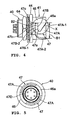
- Fig. 1 is a partially sectional exploded view of a multiphase connector according to the present invention;
- Fig. 2 is a front view of a plug connector of the multiphase connector;
- Fig. 3 is a sectional view taken along line V-V in Fig. 2;
- Fig. 4 is a side view showing a receptacle connector of the multiphase connector;
- Fig. 5 is a front view of the receptacle connector;
- Fig. 6 is an enlarged view of a part X in Fig. 4;
- Fig. 7 is an explanatory view for explaining an insertion of a locking portion into a locking groove portion;
- Fig. 8 is an exploded perspective view showing a conventional multiphase connector;
- Fig. 9 is a side view of a state that a connector is connected to a mating connector;
- Fig. 10 is a schematic side view showing an initial stage of a locking operation;
- Fig. 11 is a schematic side view showing a middle stage of the locking operation;
- Fig. 12 is a schematic side view showing a locked state
- Fig. 13 is an exploded perspective view showing another conventional multiphase connector; and
- Fig. 14 is a schematic side view showing an initial stage of a locking operation of the multiphase connector.
- As shown in Fig. 1, the multiphase connector of the present invention includes a
connector plug 1 as a connector and areceptacle 40 as a mating connector. Theconnector plug 1 includes a connector main body 1A. The connector main body 1A is formed of aplug shell 2 or a connector shell formed of metal; asleeve 3 rotatably attached to theplug shell 2 to form aconnector engaging portion 15 together with theplug shell 2; and an insulatingcase 4 formed of a synthetic resin disposed in theplug shell 2. - The
plug shell 2 is provided with apartition portion 9 at the middle of an outer circumferential surface thereof. A front portion from the partition portion 9 (left side in Fig. 1) becomes anengaging surface 10, and a rear portion from the partition portion 9 (right side in Fig. 1) becomes a cordtube connecting portion 11. As shown in Fig. 2, thepartition portion 9 is provided with a sleeverotation groove portion 11A over a range of substantially 90 degrees. The engagingsurface portion 10 is provided with an engagingpositioning groove portion 10B extending from a distal end portion to thepartition portion 9 along a direction that the connector is inserted and pulled out. As shown in Fig. 3, the cordtube connecting portion 11 is provided with asleeve supporting portion 12; a stopper ringinsertion groove portion 12A; and amale screw portion 13. An insulatingcase insertion portion 14 is formed inside theplug shell 2. - The
sleeve 3 is provided with a supportingportion 3A with a flange shape at a rear end portion thereof. As shown in Fig. 3, the supportingportion 3A is provided with a projectingportion 3b projecting in the direction that the connector is inserted and pulled out. An outer circumferential edge portion of the supportingportion 3A is chamfered, and the chamfered portion becomes aring sliding portion 3c. As shown in Fig. 2, a pair of lockingportions 3B with an engaging projecting shape is disposed on an innercircumferential surface 3a of thesleeve 3 at positions shifted by 180 degrees. - A waterproof O-
ring 25 is disposed in an O-ringinsertion groove portion 10A of theplug shell 2. Astopper ring 26 or a stopper is disposed in a stopper ringinsertion groove portion 12A. Thesleeve 3 is rotatably attached to theplug shell 2 with the supportingportion 3A supported on thesleeve supporting portion 12. A circumferential surface of thepartition portion 9 contacts with and slides on an inner circumferential surface of thesleeve 3. - The projecting
portion 3b of thesleeve 3 is inserted into the cordtube connecting portion 11A, and thering sliding portion 3c of thesleeve 3 contacts and slides on thestopper ring 26. Aspring washer 29 or a spring member is disposed between the supportingportion 3A of thesleeve 3 and thepartition portion 9. - As described above, the
sleeve 3 is rotatably attached to an outer circumferential surface of theplug shell 2 with the supportingportion 3A to be movable in the direction that the connector is inserted and pulled out, so that thepartition portion 9 contacts with and slides on the innercircumferential surface 3a of thesleeve 3. Thestopper ring 26 is disposed in the stopper ringinsertion groove portion 12A of theplug shell 2. Thespring washer 29 is disposed between the supportingportion 3A and thepartition portion 9. With an urging force of thespring washer 29, thering sliding portion 3c of thesleeve 3 contacts and slides on thestopper ring 26, thereby forming locking fixing means. - As described above, the projecting
portion 3b of thesleeve 3 is inserted into the cordtube connecting portion 11A of thepartition portion 9, thereby forming sleeve rotation restriction means. The insulatingcase 4 is inserted into the insulatingcase insertion portion 14 of theplug shell 2. The insulatingcase 4 is provided with a plurality ofterminal insertion portions 17 along an axial direction thereof. - A female screw portion 18 of a
cord tube 5 is screwed in themale screw portion 13, so that thecord tube 5 is connected to the cordtube connecting portion 11 of theplug shell 2. In this case, a waterproof O-ring 19A attached to an O-ring attaching groove portion 19 disposed in thecord tube 5 contacts and slides on an outer circumferential surface at an end portion of the cordtube connecting portion 11. A buttingsurface 20a of thecord tube 5 contacts and slides on an end surface of the cordtube connecting portion 11 of theplug shell 2. Ashield wire cable 30 passes through aninner opening portion 20 of thecord tube 5. Afemale terminal 37 is connected to an exposed portion of a conductive body 32 at an end portion of theshield wire cable 30, and is inserted into and fixed to one of theterminal insertion portions 17 of the insulatingcase 4. - When a gasket 7 is inserted into a
gasket attaching portion 21 of thecord tube 5, and a tighteningring 24 is screwed into amale screw portion 23 of thecord tube 5, ataper portion 24B disposed on an inner surface of the tighteningring 24 pushes a cord cramp 8, so that the cord cramp 8 moves toward thegasket 17 to push the gasket 7 with a distal end portion thereof. In this case, the gasket 7 is deformed in a radial direction to push theshield wire cable 30 for waterproof, and the cord cramp 8 is deformed in a radial direction to hold theshield wire cable 30. - A contact spring member 6 is attached to a spring
member attaching portion 22 of thecord tube 5 in a state compressed in a radial direction. The contact spring member 6 contacts with an outer circumferential surface of anearth metal member 36 of theshield wire cable 30. In theconnector plug 1 with the configuration described above, ashield layer 34 of theshield wire cable 30 is electrically connected to theplug shell 2 through theearth metal member 36, the contact spring member 6, and thecord tube 5. - As shown in Fig. 1 and Fig. 4, the
receptacle 40 includes areceptacle shell 41 made of metal; an insulatingcase 42 made of a synthetic resin and inserted into thereceptacle shell 41; and a plurality ofmale terminals 43 or contact terminals held with the insulatingcase 42. Thereceptacle shell 41 is provided with aflange portion 44 at a middle portion of an outer circumferential portion thereof. A front portion from the flange portion 44 (right side in Fig. 1) becomes aconnector engaging portion 46 or a mating connector engaging portion with a cylindrical shape. As shown in Fig. 5, theconnector engaging portion 46 is provided with lockinggroove portion 47 on the outer circumferential portion of theconnector engaging portion 46 at positions shifted by 180 degrees. Each of the lockinggroove portions 47 is provided with aguide groove portion 47A and an engaginggroove portion 47B connected to theguide groove portion 47A. As shown in Fig. 4, an entrance of theguide groove portion 47A has a width B1 larger than a width B2 of the engaginggroove portion 47B. - The
guide groove portion 47A has a funnel shape with a width gradually decreasing from a distal end (front edge) of the matingconnector engaging portion 46 toward theflange portion 44. Inclined cam surfaces 47A-1 and 47A-2 inclined in opposite directions are formed on both side portions of theguide groove portion 47A. The engaginggroove portion 47B is inclined in a direction perpendicular to the direction that the connector is inserted and pulled out. One ofside surface portions 47B-1 of the engaginggroove portion 47B is connected to one of the inclined cam surfaces 47A-1 of theguide groove portion 47A, and the other of theside surface portions 47B-2 of the engaginggroove portion 47B is connected to the other of the inclined cam surfaces 47A-2 of theguide groove portion 47A. - A
cam portion 47a is disposed on the one of theside surface portions 47B-1 of the engaginggroove portion 47B as a bulge portion. A lockingseat portion 47b is disposed between thecam portion 47a and anend surface portion 47c of the engaginggroove portion 47B. As shown in Fig. 5, an engagingpositioning projecting portion 47D is formed on an inner circumferential surface of theconnector engaging portion 46 along the direction that the connector is inserted and pulled out. A male screw portion 48A is formed on a cylindrical portion 48 at a rear side (left side in Fig. 1) of theflange portion 44. An insulatingcase insertion portion 49 is formed inside thereceptacle shell 41. - The insulating
case 42 is inserted into the insulatingcase insertion portion 49. Themale terminals 43 are fitted interminal insertion portions 50 of the insulatingcase 42.Contact portions 43A of themale terminals 43 are inserted into theconnector engaging portion 46. Acontact member 51 with a ring shape is inserted into theconnector engaging portion 46. Thecontact member 51 has a shape waving in a circumferential direction, and a backside surface of thecontact member 51 contacts with thereceptacle shell 41. Locking means is formed of the lockingportions 3B disposed on thesleeve 3 of theconnector plug 1; the lockinggroove portions 47 disposed on theconnector engaging portion 46 of thereceptacle 40; and the locking fixing means. - A process of connecting and releasing the connection between the
connector plug 1 and thereceptacle 40 thus configured will be explained next. - As shown in Fig. 1, the screw portion 48 of the
receptacle shell 41 is inserted into, for example, an attachinghole 61 in awall portion 60 of a conductive housing (not shown) of an electrical device. Then, awasher 63 is placed on the screw portion 48 and a tighteningnut 64 is screwed and tightened in the screw portion 48, so that theflange portion 44 and thewasher 63 sandwich the wall portion of the housing, thereby attaching thereceptacle 40 to the housing. In this case, the waterproof O-ring 52 attached to the O-ring attaching portion 45 on theflange portion 44 abuts against the wall portion 66. - With the engaging
positioning groove portion 10B and the engagingpositioning projecting portion 47D, theconnector plug 1 and thereceptacle 40 engage and are positioned. Then, theconnector engaging portion 46 of thereceptacle shell 41 is fitted in theconnector engaging portion 15 of theconnector plug 1, so that connecting portions of thefemale terminals 37 are connected to thecontact portions 43A of themale terminals 43, and a distal end portion 2A of theplug shell 2 contacts with thereceptacle shell 41 through thecontact member 51. - In the locking means described above, when the
connector engaging portion 46 of thereceptacle shell 41 is fitted in theconnector engaging portion 15 of theconnector plug 1, theconnector plug 1 and thereceptacle 40 engage and are, positioned with the engagingpositioning groove portion 10B and the engagingpositioning projecting portion 47D. The lockingportion 3B of thesleeve 3 is inserted into theguide groove portion 47A of the lockinggroove portions 47 of theconnector engaging portion 46, and thesleeve 3 is rotated, so that the lockingportion 3B detachably engages the engaginggroove portion 47B. - As indicated by a Japanese character "i" arrow in Fig. 7, there is a case that the locking
portion 3B slides on theinclined cam surface 47A-1 and inserted into the engaginggroove portion 47B to reach the lockingseat portion 47b. Also, as indicated by a Japanese character "ro" arrow in Fig. 7, there is a case that the lockingportion 3B slides on the otherinclined cam surface 47A-2 and inserted into the engaginggroove portion 47B to reach the lockingseat portion 47b. In both cases, when the lockingportion 3B reaches the lockingseat portion 47b, thespring washer 29 pushes thesleeve 3 in the right direction in Fig. 1 with an urging force (spring force) thereof, so that the lockingportion 3B is seated on the lockingseat portion 47b. In this case, even though thesleeve 3 tries to rotate in an opposite direction, thecam portion 47a interferes with the lockingportion 3B, so that thesleeve 3 does not rotate in the opposite direction. - As described above, in the state that the
connector engaging portion 46 completely engages theconnector engaging portion 15, the distal end portion 2A of theplug shell 2 contacts with thereceptacle shell 41 through thecontact member 51. Accordingly, theshield layer 34 of theshield wire cable 30 is electrically connected to thewall portion 60 of the housing of the electrical device through theearth metal member 36, the contact spring member 6, thecord tube 5, theplug shell 2, thecontact member 51, and thereceptacle shell 41. When the engagement between theconnector plug 1 and thereceptacle 40 is released, thesleeve 3 is rotated in reverse. Accordingly, the lockingportion 3B moves out of the engaginggroove portion 47B over thecam portion 47a to slide and contact with theinclined cam surface 47A-2 of theguide groove portion 47A, so that theconnector plug 1 can be pulled out from thereceptacle 40. - As explained above, in the embodiments of the present invention, the locking
portion 3B of thesleeve 3 is inserted into theguide groove portion 47A of the lockinggroove portions 47 of theconnector engaging portion 46, and thesleeve 3 is rotated. When the lockingportion 3B slides on thecam portion 47a and reaches the lockingseat portion 47b, thespring washer 29 pushes the lockingportion 3B through thesleeve 3 to be seated on the lockingseat portion 47b, thereby completing the locking. When the engagement is released, thesleeve 3 is rotated in reverse, so that the lockingportion 3B moves out the lockingseat portion 47b through thecam portion 47a to theguide groove portion 47A. - Accordingly, as compared with the conventional connector, it is not necessary to restrict the rotational angle of the sleeve (positioning) at an initial position. Therefore, it is not necessary to move the sleeve forward for releasing the rotational restriction of the sleeve, thereby making it possible to reduce a whole size of the connector. Further, it is not necessary to arrange a torsion coil spring for inserting each engaging pin into a lock portion of each cam groove to lock, thereby eliminating a step of fixing the torsion coil spring and making it easy to assemble.
- In the embodiments of the present invention, the
sleeve 3 is rotatably attached to the outer circumference surface of theplug shell 2 with the supportingportion 3A to be movable in the direction that the connector is inserted and pulled out. Thepartition portion 9 slides and contacts with the inner circumference surface of thesleeve 3. Thestopper ring 26 is provided on the stopper ringinsertion groove portion 12A of theplug shell 2. Thespring washer 29 is disposed between the supportingportion 3A and thepartition portion 9 for urging the supportingportion 3A to slide and contact with thestopper ring 26, thereby forming the locking fixing means. Accordingly, in the locking fixing portion, thespring washer 29 is compressed when the lockingportion 3B moves on thecam portion 47a. When the lockingportion 3B is seated on the lockingseat portion 47b, thespring washer 29 presses the lockingportion 3B against the lockingseat portion 47b, thereby securely seating the lockingportion 3B on the lockingseat portion 47b. Accordingly, thecam portion 47a interferes with the lockingportion 3B not to move, thereby securing the locking. Further, thesleeve 3 does not come off theplug shell 2 with thestopper ring 26. Accordingly, when theplug connector 1 is disassembled, thesleeve 3 does not come off, thereby making it easy to disassemble and assemble. - In the embodiments of the present invention, the sleeve
rotation groove portion 11A is formed in thepartition portion 9 over a specific angle range. The projectingportion 3b is disposed on the supportingportion 3A. The projectingportion 3b is inserted into the sleeverotation groove portion 11A to set a rotational range of thesleeve 3. Accordingly, it is possible to set the rotational range of thesleeve 3 according to a position of the lockinggroove portion 47. - In the embodiments of the present invention, the
guide groove portion 47A has a funnel shape with a width gradually decreasing from the distal end of theconnector engaging portion 46 in the direction that the connector is inserted and pulled out. The inclined cam surfaces 47A-1 and 47A-2 inclined in opposite directions are formed on both side portions of theguide groove portion 47A. The engaginggroove portion 47B is inclined in a direction perpendicular to the direction that the connector is inserted and pulled out. One of theside surface portions 47B-1 is connected to one of the inclined cam surfaces 47A-1, and the other of theside surface portions 47B-2 is connected to the other of the inclined cam surfaces 47A-2. The bulge portion is disposed on the one of theside surface portions 47B-1 as thecam portion 47a. Thecam portion 47a positions the lockingseat portion 47b at the end portion of the engaginggroove portion 47B. Accordingly, when theconnector plug 1 is fitted in thereceptacle 40, the lockingportion 3B slides against one or the other of the inclined cam surfaces 47A-1 and 47A-2 to the position in Fig. 7 to rotate thesleeve 3. As a result, the lockingportion 3B is inserted into the engaginggroove portion 47B, and reaches the lockingseat portion 47b through moving over thecam portion 47a. Thespring washer 29 urges the lockingportion 3B to be seated , on the lockingseat portion 47b. In this state, thecam portion 47a interferes with the lockingportion 3B not to move, thereby securing the locking. - According to the multiphase connector of the present invention, it is possible to reduce a whole size of the connector. It is easy to assemble the connector. The sleeve does not come off the connector shell with the stopper. Accordingly, when the connector is disassembled, the sleeve does not come off, thereby making it easy to disassemble and assemble. Therefore, the multiphase connector of the present invention is useful as an electrical connector.
Claims (5)
- A multiphase connector, comprising:a connector engaging portion of a connector for engaging a mating connector engaging portion of a mating connector so that a contact terminal of the multiphase connector contacts with a contact terminal of the mating connector, andlock means for connecting the connector to the mating connector; whereinsaid connector engaging portion includes a connector main body and a sleeve attached to the connector main body to be rotatable within a specific angle;said lock means includes a locking portion disposed on the sleeve and a locking groove portion disposed on the mating connector engaging portion;said locking groove portion includes a guide groove portion for guiding the locking portion when the sleeve is rotated, and an engaging groove portion for detachably engaging the locking portion when the sleeve is further rotated; andan entrance portion of the guide groove portion has a width larger than that of the engaging groove portion. Sleeve rotation restricting means is provided for restricting a rotational amount of the sleeve upon engaging between the guide groove portion and the engaging groove portion.
- The multiphase connector according to claim 1, wherein said sleeve is movable within a specific amount in a direction that the connector is inserted and pulled out; said locking means includes locking fixing means; said engaging groove portion includes a cam portion and a locking seat portion; said locking fixing means includes a spring member to be compressed when the locking portion slides against the cam portion upon rotating the sleeve; and said spring member urges the locking portion to be seated on the locking seat portion.
- The multiphase connector according to claim 1 or 2, wherein said connector includes a connector shell; said connector shell is provided with a partition portion on an outer circumferential surface thereof; said sleeve includes a supporting portion at an end portion thereof; said sleeve is attached to the outer circumferential surface of the connector shell with the supporting portion to be rotatable and movable in a direction that the connector is inserted and pulled out so that the partition portion slides on an inner circumferential surface of the sleeve; a stopper is provided on the outer circumferential surface of the connector shell; and said spring member is disposed between the supporting portion and the partition portion for urging the supporting portion to slide against the stopper, thereby forming the locking fixing means.
- The multiphase connector according to claim 3, wherein said sleeve rotation restricting means includes a sleeve rotation groove portion in the partition portion over a specific angle range; a projecting portion is disposed on the supporting portion; and said projecting portion is inserted into the sleeve rotation groove portion to regulate a rotational range of the sleeve.
- The multiphase connector according to claim 2, 3, or 4, wherein said guide groove portion has a funnel shape with a width gradually decreasing from a distal end of the mating connector engaging portion in the direction that the connector is inserted and pulled out; inclined cam surfaces inclined in opposite directions are formed on both side portions of the guide groove portion; said engaging groove portion is inclined in a direction perpendicular to the direction that the connector is inserted and pulled out; one of side surface portions of the engaging groove portion is connected to one of the inclined cam surfaces; the other of the side surface portions is connected to the other of the inclined cam surfaces; a bulge portion is disposed on the one of the side surface portions as the cam portion; and said cam portion positions the locking seat portion at an end portion of the engaging groove portion.
Applications Claiming Priority (1)
| Application Number | Priority Date | Filing Date | Title |
|---|---|---|---|
| JP2004251007A JP4247542B2 (en) | 2004-08-30 | 2004-08-30 | Multi-pole connector |
Publications (3)
| Publication Number | Publication Date |
|---|---|
| EP1630905A2 true EP1630905A2 (en) | 2006-03-01 |
| EP1630905A3 EP1630905A3 (en) | 2006-03-15 |
| EP1630905B1 EP1630905B1 (en) | 2010-04-14 |
Family
ID=35431040
Family Applications (1)
| Application Number | Title | Priority Date | Filing Date |
|---|---|---|---|
| EP05018485A Active EP1630905B1 (en) | 2004-08-30 | 2005-08-25 | Multiphase connector |
Country Status (6)
| Country | Link |
|---|---|
| US (1) | US7011544B1 (en) |
| EP (1) | EP1630905B1 (en) |
| JP (1) | JP4247542B2 (en) |
| KR (1) | KR20060050692A (en) |
| DE (1) | DE602005020553D1 (en) |
| TW (1) | TW200618413A (en) |
Cited By (3)
| Publication number | Priority date | Publication date | Assignee | Title |
|---|---|---|---|---|
| EP2071676A2 (en) * | 2007-12-14 | 2009-06-17 | Quirin Grawe | Connector assembly |
| EP1837957A3 (en) * | 2006-03-25 | 2009-07-01 | Tehalit GmbH | Bayonet lock with self contact |
| CN106099569A (en) * | 2016-07-18 | 2016-11-09 | 中国核动力研究设计院 | A kind of thermocouple electrical cnnector |
Families Citing this family (19)
| Publication number | Priority date | Publication date | Assignee | Title |
|---|---|---|---|---|
| PT2220729T (en) * | 2007-11-13 | 2017-12-29 | Linak As | An actuator system |
| WO2012052870A1 (en) * | 2010-10-19 | 2012-04-26 | Koninklijke Philips Electronics N.V. | Compact replaceable led module |
| DE102011018993A1 (en) * | 2011-04-28 | 2012-10-31 | Mc Technology Gmbh | Screen contact spring |
| CN102646888B (en) * | 2012-04-09 | 2014-02-05 | 中航光电科技股份有限公司 | Socket, socket assembly and connector assembly |
| US8608496B2 (en) | 2012-04-25 | 2013-12-17 | Pratt & Whitney Canada Corp. | Connector for multi-phase conductors |
| JP5886684B2 (en) * | 2012-05-23 | 2016-03-16 | 矢崎総業株式会社 | connector |
| TWI477013B (en) * | 2012-07-12 | 2015-03-11 | Acbel Polytech Inc | Power supply of the shell of the cable waterproof structure |
| JP6259969B2 (en) * | 2013-05-31 | 2018-01-17 | 丸一株式会社 | Release wire connection structure of remote-controlled drain plug device |
| CN203646503U (en) * | 2013-11-29 | 2014-06-18 | 刘秋明 | Electronic cigarette device |
| TWM520748U (en) * | 2015-10-16 | 2016-04-21 | T Conn Prec Corp | Circular rapid connector |
| CN108604757A (en) * | 2016-02-25 | 2018-09-28 | 莫列斯有限公司 | Electric connector |
| CN105846244B (en) * | 2016-03-29 | 2018-02-16 | 中航光电科技股份有限公司 | A kind of electric connector and electric coupler component |
| DE102017118014B3 (en) | 2017-08-08 | 2018-07-12 | Phoenix Contact Gmbh & Co. Kg | Connector part with a locking element |
| US11165205B2 (en) * | 2019-04-19 | 2021-11-02 | Dana Tm4 Inc. | Multi-phase connector for electric powertrain system |
| AT523135B1 (en) * | 2019-11-14 | 2022-09-15 | Neutrik Ag | Contact carriers for electrical connectors and connectors therefor |
| TWI728578B (en) * | 2019-11-28 | 2021-05-21 | 劉達民 | Quick joint structure with pressing and rotating lock/unlock |
| CN113067194B (en) * | 2021-03-19 | 2023-05-12 | 昆山欧德斯电子科技有限公司 | Terminal electric connector and electric connector combination thereof |
| US11424574B1 (en) * | 2021-03-23 | 2022-08-23 | Kunshan Outdoor Solutions Electronics Co., Ltd. | Terminal electrical connector and electrical connector assembly comprising thereof |
| CN116315886B (en) * | 2023-05-22 | 2023-08-08 | 长春捷翼汽车科技股份有限公司 | Circular connector |
Citations (2)
| Publication number | Priority date | Publication date | Assignee | Title |
|---|---|---|---|---|
| JPH11339890A (en) | 1998-05-29 | 1999-12-10 | Hosiden Corp | Connector with locking mechanism |
| JP2001267006A (en) | 2000-03-17 | 2001-09-28 | Japan Aviation Electronics Industry Ltd | Connector |
Family Cites Families (13)
| Publication number | Priority date | Publication date | Assignee | Title |
|---|---|---|---|---|
| US3512119A (en) * | 1966-09-20 | 1970-05-12 | Bunker Ramo | Electrical connector |
| US5662488A (en) * | 1996-10-31 | 1997-09-02 | Alden; Peter H. | Quick connect coupling system for rapidly joining connectors and/or other elongated bodies |
| US6226068B1 (en) * | 1999-08-27 | 2001-05-01 | Amphenol Corporation | Self-locking bayonet coupling mechanism |
| US6575786B1 (en) * | 2002-01-18 | 2003-06-10 | Adc Telecommunications, Inc. | Triaxial connector and method |
| US6692285B2 (en) * | 2002-03-21 | 2004-02-17 | Andrew Corporation | Push-on, pull-off coaxial connector apparatus and method |
| JP2003282193A (en) * | 2002-03-22 | 2003-10-03 | Sharp Corp | Coaxial contact plug and converter for receiving satellite broadcasting provided with the same |
| US6866543B2 (en) * | 2003-04-09 | 2005-03-15 | Insert Enterprise Co., Ltd. | Module type mini BNC connector |
| US6790083B1 (en) * | 2003-07-10 | 2004-09-14 | Chiung-Ling Chen | Signal line connector |
| US6808407B1 (en) * | 2003-08-22 | 2004-10-26 | Agilent Technologies, Inc. | Locking precision male BNC connector with latch mechanism allowing cable rotation |
| US6884113B1 (en) * | 2003-10-15 | 2005-04-26 | John Mezzalingua Associates, Inc. | Apparatus for making permanent hardline connection |
| US6824392B1 (en) * | 2003-10-27 | 2004-11-30 | Pony Guo | RCA connector capable of being inserted into circuit board directly |
| US20050136735A1 (en) * | 2003-12-17 | 2005-06-23 | Thomas & Betts International, Inc. | Coaxial connector having improved locking sleeve |
| DE202004002078U1 (en) * | 2004-02-11 | 2004-04-15 | Harting Electric Gmbh & Co. Kg | Universal in-line electrical connector has a bayonet contacts with threaded connection or push-in latched connection |
-
2004
- 2004-08-30 JP JP2004251007A patent/JP4247542B2/en active Active
-
2005
- 2005-08-17 US US11/205,131 patent/US7011544B1/en active Active
- 2005-08-24 TW TW094128995A patent/TW200618413A/en unknown
- 2005-08-25 EP EP05018485A patent/EP1630905B1/en active Active
- 2005-08-25 DE DE602005020553T patent/DE602005020553D1/en active Active
- 2005-08-26 KR KR1020050078684A patent/KR20060050692A/en not_active Application Discontinuation
Patent Citations (2)
| Publication number | Priority date | Publication date | Assignee | Title |
|---|---|---|---|---|
| JPH11339890A (en) | 1998-05-29 | 1999-12-10 | Hosiden Corp | Connector with locking mechanism |
| JP2001267006A (en) | 2000-03-17 | 2001-09-28 | Japan Aviation Electronics Industry Ltd | Connector |
Cited By (4)
| Publication number | Priority date | Publication date | Assignee | Title |
|---|---|---|---|---|
| EP1837957A3 (en) * | 2006-03-25 | 2009-07-01 | Tehalit GmbH | Bayonet lock with self contact |
| EP2071676A2 (en) * | 2007-12-14 | 2009-06-17 | Quirin Grawe | Connector assembly |
| EP2071676A3 (en) * | 2007-12-14 | 2012-05-02 | Quirin Grawe | Connector assembly |
| CN106099569A (en) * | 2016-07-18 | 2016-11-09 | 中国核动力研究设计院 | A kind of thermocouple electrical cnnector |
Also Published As
| Publication number | Publication date |
|---|---|
| TW200618413A (en) | 2006-06-01 |
| KR20060050692A (en) | 2006-05-19 |
| EP1630905A3 (en) | 2006-03-15 |
| EP1630905B1 (en) | 2010-04-14 |
| DE602005020553D1 (en) | 2010-05-27 |
| JP4247542B2 (en) | 2009-04-02 |
| TWI314798B (en) | 2009-09-11 |
| US20060046566A1 (en) | 2006-03-02 |
| JP2006066354A (en) | 2006-03-09 |
| US7011544B1 (en) | 2006-03-14 |
Similar Documents
| Publication | Publication Date | Title |
|---|---|---|
| EP1630905B1 (en) | Multiphase connector | |
| US6361348B1 (en) | Right angle, snap on coaxial electrical connector | |
| US5595499A (en) | Coaxial connector having improved locking mechanism | |
| US7367833B2 (en) | Connector with anti-rotation and anti-return mechanisms | |
| JP5449033B2 (en) | connector | |
| JP3292462B2 (en) | Connector with locking mechanism | |
| TWI459655B (en) | Connector and connector unit | |
| US8333605B2 (en) | Locking apparatus for electrical connectors | |
| US20120135629A1 (en) | Securable multi-conductor cable connection pair having threaded insert | |
| GB2438478A (en) | Connector with lock securing member having a lock releasing portion | |
| US20080268692A1 (en) | Electric socket | |
| US5791939A (en) | Shielded connector | |
| US10141688B2 (en) | Plug connector with resilient engagement element and seal | |
| KR20170136642A (en) | A set of plug connectors and plug connectors | |
| US5489222A (en) | Mini connector with anti-rotational contact | |
| JPH07220801A (en) | Connector | |
| US9362671B2 (en) | Coaxial cable connector with quick-locking connection | |
| JP5303348B2 (en) | Lock structure and electrical connector using the lock structure | |
| JP3388438B2 (en) | connector | |
| US20230361506A1 (en) | Locking electrical contact device with switch | |
| US8435061B2 (en) | Connector | |
| CN217087011U (en) | Connector assembly | |
| US6443778B1 (en) | Electrical connector assembly | |
| JP2009289644A (en) | Connector | |
| JP2003282175A (en) | Locking structure of pin terminal |
Legal Events
| Date | Code | Title | Description |
|---|---|---|---|
| PUAI | Public reference made under article 153(3) epc to a published international application that has entered the european phase |
Free format text: ORIGINAL CODE: 0009012 |
|
| PUAL | Search report despatched |
Free format text: ORIGINAL CODE: 0009013 |
|
| AK | Designated contracting states |
Kind code of ref document: A2 Designated state(s): AT BE BG CH CY CZ DE DK EE ES FI FR GB GR HU IE IS IT LI LT LU LV MC NL PL PT RO SE SI SK TR |
|
| AX | Request for extension of the european patent |
Extension state: AL BA HR MK YU |
|
| AK | Designated contracting states |
Kind code of ref document: A3 Designated state(s): AT BE BG CH CY CZ DE DK EE ES FI FR GB GR HU IE IS IT LI LT LU LV MC NL PL PT RO SE SI SK TR |
|
| AX | Request for extension of the european patent |
Extension state: AL BA HR MK YU |
|
| 17P | Request for examination filed |
Effective date: 20060912 |
|
| 17Q | First examination report despatched |
Effective date: 20061020 |
|
| AKX | Designation fees paid |
Designated state(s): CH DE FR LI |
|
| 17Q | First examination report despatched |
Effective date: 20061020 |
|
| GRAP | Despatch of communication of intention to grant a patent |
Free format text: ORIGINAL CODE: EPIDOSNIGR1 |
|
| GRAS | Grant fee paid |
Free format text: ORIGINAL CODE: EPIDOSNIGR3 |
|
| GRAA | (expected) grant |
Free format text: ORIGINAL CODE: 0009210 |
|
| AK | Designated contracting states |
Kind code of ref document: B1 Designated state(s): CH DE FR LI |
|
| REG | Reference to a national code |
Ref country code: CH Ref legal event code: EP |
|
| REF | Corresponds to: |
Ref document number: 602005020553 Country of ref document: DE Date of ref document: 20100527 Kind code of ref document: P |
|
| PLBE | No opposition filed within time limit |
Free format text: ORIGINAL CODE: 0009261 |
|
| STAA | Information on the status of an ep patent application or granted ep patent |
Free format text: STATUS: NO OPPOSITION FILED WITHIN TIME LIMIT |
|
| 26N | No opposition filed |
Effective date: 20110117 |
|
| REG | Reference to a national code |
Ref country code: CH Ref legal event code: PL |
|
| PG25 | Lapsed in a contracting state [announced via postgrant information from national office to epo] |
Ref country code: LI Free format text: LAPSE BECAUSE OF NON-PAYMENT OF DUE FEES Effective date: 20100831 Ref country code: CH Free format text: LAPSE BECAUSE OF NON-PAYMENT OF DUE FEES Effective date: 20100831 |
|
| REG | Reference to a national code |
Ref country code: FR Ref legal event code: ST Effective date: 20110502 |
|
| PG25 | Lapsed in a contracting state [announced via postgrant information from national office to epo] |
Ref country code: FR Free format text: LAPSE BECAUSE OF NON-PAYMENT OF DUE FEES Effective date: 20100831 |
|
| REG | Reference to a national code |
Ref country code: DE Ref legal event code: R082 Ref document number: 602005020553 Country of ref document: DE Representative=s name: SCHAEFER PATENT- UND RECHTSANWAELTE, DE Ref legal event code: R082 Country of ref document: DE Representative=s name: SCHAEFER, MATTHIAS W., DIPL.-ING., DE Ref country code: DE Ref document number: 602005020553 |
|
| REG | Reference to a national code |
Ref country code: DE Ref legal event code: R082 Ref document number: 602005020553 Country of ref document: DE Representative=s name: SCHAEFER, MATTHIAS W., DIPL.-ING., DE |
|
| REG | Reference to a national code |
Ref country code: DE Ref legal event code: R082 Ref document number: 602005020553 Country of ref document: DE Representative=s name: SCHAEFER, MATTHIAS W., DIPL.-ING., DE |
|
| PGFP | Annual fee paid to national office [announced via postgrant information from national office to epo] |
Ref country code: DE Payment date: 20230627 Year of fee payment: 19 |