EP1629768A2 - Sensor attachment system for an electrode array - Google Patents
Sensor attachment system for an electrode array Download PDFInfo
- Publication number
- EP1629768A2 EP1629768A2 EP05076748A EP05076748A EP1629768A2 EP 1629768 A2 EP1629768 A2 EP 1629768A2 EP 05076748 A EP05076748 A EP 05076748A EP 05076748 A EP05076748 A EP 05076748A EP 1629768 A2 EP1629768 A2 EP 1629768A2
- Authority
- EP
- European Patent Office
- Prior art keywords
- skin
- attachment system
- sensor attachment
- electrode array
- electrode
- Prior art date
- Legal status (The legal status is an assumption and is not a legal conclusion. Google has not performed a legal analysis and makes no representation as to the accuracy of the status listed.)
- Withdrawn
Links
Images


Classifications
-
- A—HUMAN NECESSITIES
- A61—MEDICAL OR VETERINARY SCIENCE; HYGIENE
- A61B—DIAGNOSIS; SURGERY; IDENTIFICATION
- A61B5/00—Measuring for diagnostic purposes; Identification of persons
- A61B5/48—Other medical applications
- A61B5/4887—Locating particular structures in or on the body
- A61B5/4893—Nerves
-
- A—HUMAN NECESSITIES
- A61—MEDICAL OR VETERINARY SCIENCE; HYGIENE
- A61B—DIAGNOSIS; SURGERY; IDENTIFICATION
- A61B5/00—Measuring for diagnostic purposes; Identification of persons
- A61B5/05—Detecting, measuring or recording for diagnosis by means of electric currents or magnetic fields; Measuring using microwaves or radio waves
- A61B5/053—Measuring electrical impedance or conductance of a portion of the body
- A61B5/0531—Measuring skin impedance
-
- A—HUMAN NECESSITIES
- A61—MEDICAL OR VETERINARY SCIENCE; HYGIENE
- A61B—DIAGNOSIS; SURGERY; IDENTIFICATION
- A61B5/00—Measuring for diagnostic purposes; Identification of persons
- A61B5/24—Detecting, measuring or recording bioelectric or biomagnetic signals of the body or parts thereof
-
- A—HUMAN NECESSITIES
- A61—MEDICAL OR VETERINARY SCIENCE; HYGIENE
- A61B—DIAGNOSIS; SURGERY; IDENTIFICATION
- A61B5/00—Measuring for diagnostic purposes; Identification of persons
- A61B5/24—Detecting, measuring or recording bioelectric or biomagnetic signals of the body or parts thereof
- A61B5/25—Bioelectric electrodes therefor
- A61B5/279—Bioelectric electrodes therefor specially adapted for particular uses
- A61B5/28—Bioelectric electrodes therefor specially adapted for particular uses for electrocardiography [ECG]
- A61B5/282—Holders for multiple electrodes
-
- A—HUMAN NECESSITIES
- A61—MEDICAL OR VETERINARY SCIENCE; HYGIENE
- A61B—DIAGNOSIS; SURGERY; IDENTIFICATION
- A61B2562/00—Details of sensors; Constructional details of sensor housings or probes; Accessories for sensors
- A61B2562/04—Arrangements of multiple sensors of the same type
- A61B2562/046—Arrangements of multiple sensors of the same type in a matrix array
Definitions
- This invention relates to a medical device for the non-invasive location and imaging of peripheral nerves.
- the present invention relates to a sensor attachment system for use at the skin surface with an electrode array assembly having one or more electrodes. Each electrode in the electrode array assembly maintains a connection to peripheral nerve detection and imaging instrumentation.
- One or more return wires are attached to the electrode array assembly and to a skin surface electrode during use of the sensor system.
- a disposable, sterile sensor attachment system allows conductance between the electrode array and the skin surface of the subject.
- the sensor attachment system contains individual conductor islands, each adapted to align accurately with a specific electrode of the electrode array.
- the layer of the sensor attachment system that adheres to the skin surface of the subject may be left on the skin at the end of sampling to provide a skin marking guide. This facilitates the positioning of needles for subsequent nerve stimulation or therapy.
- U.S. Pat. No. 4,016,870 to Lock describes a system for acupuncture point location in which a single, hand-held probe of undisclosed composition is used to determine sites of high skin surface conductance.
- U.S. Pat. No. 5,897,505 to Feinberg, et al. describes a system for measuring selective tissue conductance and temperature utilizing chrome-plated, brass electrodes in a handheld embodiment. Although each of these systems measures conductance at the skin surface, they suffer two main drawbacks. First, metallic electrodes display uneven current densities at the skin surface-electrode interface, which is largely dependent on the underlying moisture pattern of the skin.
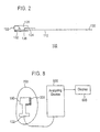
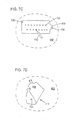
- FIG. 9 is a circuit diagram of the non-invasive, peripheral nerve mapping device according to the U.S. Pat No. 5,560,372 to Cory as it is positioned over the forearm of a patient.
- the sampling electrode (10) depicted herein comprises eight electrodes (10a-h) having leads (41) arranged in a linear array and applied to the volar surface of the forearm on the epidermal surface (80).
- the reference electrode (70) is placed on the dorsal forearm.
- a constant current output is applied between the two electrodes (10, 70) on the epidermal surface (80).
- the voltage difference V between the two electrodes is measured and varies from adjacent skin sites as the electrical conductance of the skin changes.
- the reference electrode (70) may comprise a conductive carbon impregnated silastic pad provided with an insulated metal foil sheet laminated thereto. The metal foil sheet is in electrical contact with a connector element.
- the reference electrode may further contain adhesive layer laminated to the bottom of the silastic pad provided with a silicon release sheet attached to the adhesive layer.
- Reference electrode may comprise a carbon-impregnated silastic pad provided with a layer of pharmaceutical electrode gel placed on the bottom of the pad to be positioned against the skin.
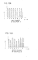
- FIG. 10(A) depicts the constant current input (I) for each sub-electrode (10a through 10h), numbers 1-8 respectively, as shown in FIG. 9.
- FIG. 10(B) depicts the voltage output V for each sub-electrode.
- electrode number (10b), number 2 in FIG. 10(B) is positioned over ulnar nerve (88):
- electrode (10b) indicates the position of the ulnar nerve (88) by a decrease in output voltage.
- electrodes (10d) and (10e), numbers 4 and 5 in FIG. 10(B) display a similar output voltage decrease as they are positioned over median nerve (84).
- the non-invasive, peripheral nerve mapping device accurately identifies the location of subcutaneous nerves. Voltage minima (conductance maxima) are observed over the ulnar median nerves (88, 84) at constant current. Sites of decreased skin voltage differentials are mapped and have been shown by nerve stimulator technique, direct dissection and local anaesthetic blockage, in animal and human models, to correspond to the location of subcutaneous nerves.
- a sensor attachment system for attaching an electrode array to the skin, comprising: a skin marking guide layer having at least one marking hole therein; a support layer having one conductor island hole corresponding to each marking hole in the skin marking guide layer, each said conductor island hole containing a conductor island which projects into its corresponding marking hole; wherein the skin marking guide layer and the support layer are detachably affixed one to the other.
- a preferred sensor system comprises an electrode array and a sensor attachment system to attach to the skin.
- both the electrode array and the sensor attachment system are presented in the form of complementary arrays of electrodes and conductor islands, respectively.
- the electrode array comprises one or more electrodes, advantageously four or more electrodes.
- the electrodes may be arranged randomly, in a single line, or in another fixed order.
- the electrodes of the array may be arranged in plural rows.
- the adjacent rows may be in line with one another or offset with respect to their nearest neighbour(s).
- a preferred arrangement is for the array to comprise a minimum of four electrodes arranged as two or more rows, where adjacent rows are in line with one another.
- Another preferred arrangement is for the array to comprise a minimum of four electrodes arranged as two or more rows of electrodes, where adjacent rows are offset with respect to one another.
- a further preferred arrangement is for there to be a minimum of two rows of four or more electrodes each.
- a further preferred arrangement is for there to be a minimum of two rows of eight or more electrodes each.
- Another further preferred arrangement is for there to be a minimum of eight rows of eight electrodes each.
- An exemplary embodiment is a two row array, as depicted in FIG 1, where an offset arrangement of adjacent rows is used.
- Another exemplary embodiment is an eight row arrangement, as depicted in FIG. 4, where adjacent rows are in line with one another.
- An electrode array assembly may advantageously be made flexible so that the electrode array assembly may conform to a wide variety of body surfaces, locations and circumferences.
- the electrode array should comprise as a support structure a flexible, electrically non-conductive sheet.
- the electrical connections may also comprise suitably applied metallic ink, metallic wire, or conductive trace.
- the electrode array may be reused, a feature which is particularly achieved when the electrode array is used with a separate sensor attachment system.
- the electrode surface should be chemically, as well as biologically, inert. In other words, the electrode surface should not chemically react with, or be degraded by, surfaces which it will contact during normal use. To obtain reproducible measurements, the formation of thin, oxidation films on the electrode surface must be avoided. At the same time, the electrode array must be resistant to damage by bending and twisting. The electrode array must also be stable when cleaned with common sterilizing agents, such as isopropyl alcohol. The electrode array must also be stable upon sterilization by ethylene oxide, gamma radiation, or autoclaving. Suitable materials for the electrode surfaces include gold, gold-plated copper, nickel-plated metal, platinum, palladium, silver-silver chloride or another conductive metal, metal salt combination or conductive polymer(s) such as polyaniline.
- the preferred arrays may be advantageously practiced by constructing electrode arrays in which the electrode diameters are in the range of about 2-3 mm, with edge-to-edge spacing of about 3 mm. Smaller electrode diameters and closer electrode spacing may result in excessive variation between sample readings. It is believed that, at smaller electrode diameters, conductor resistance increases due to decreasing cross-sectional area in relation to the electrical field path, which may introduce variation in sample readings. However, where such variations are tolerable, smaller electrode diameters may be used. Of course, larger electrode diameters and spacings may be advantageously employed, although smaller diameters are generally preferred due to their generally more favorable resolution characteristics. The ordinary artisan will appreciate that a wide variety of electrode diameters and spacings may be used.
- the sensor attachment system provides an interface between the electrode array and the skin surface of a living being, preferably a mammal, more preferably a human patient.
- the sensor attachment system comprises a plurality of layers.
- One layer hereinafter the support layer, contains a plurality of conductor-islands arranged in a support.
- the conductor-islands are formed from a suitable conductive material such as a hydrogel, or silver-silver chloride gel.
- Another layer, hereinafter the skin marking guide layer is fenestrated (i.e. has holes) so that the conductor islands protrude through the holes therein.
- the support layer and the skin marking guide layer are held together by an adhesive that is easily broken, so that after imaging the peripheral nerves, the practitioner may then peel the support layer away from the skin marking guide layer, leaving the latter attached to the skin.
- the hydrogel or silver-silver chloride gel may be any electrically conductive hydrogel or silver-silver chloride gel known in the medicinal, biofeedback or biological testing arts.
- the hydrogel polymers are desirably water interactive and/or hydrophilic in nature and are of a molecular weight or structure, or have been modified such that they absorb significant quantities of water and may form hydrogels when placed in contact with water or aqueous media for a period of time sufficient to reach equilibrium with water, but which do not fully dissolve at equilibrium in water.
- the hydrogel polymers include polymers from the group of homo- and copolymers based on various combinations of the following vinyl monomers: acrylic and methacrylic acids, acrylamide, methacrylamide, hydroxyethylacrylate ormethacrylate, vinylpyrrolidones, as well as polyvinyalcohol and its co- and terpolymers, polyvinylacetate, its co- and terpolymers with the above listed monomers and 2-acrylamido-2-methyl-propanesulfonic acid (AMPS®) and sulfonated styrenes.
- vinyl monomers acrylic and methacrylic acids, acrylamide, methacrylamide, hydroxyethylacrylate ormethacrylate, vinylpyrrolidones, as well as polyvinyalcohol and its co- and terpolymers, polyvinylacetate, its co- and terpolymers with the above listed monomers and 2-acrylamido-2-methyl-propanesulfonic acid (AMPS®)
- the hydrogels of the invention should be composed of synthetic copolymers from the group of acrylic and methacrylic acids, acrylamide, methacrylamide, hydroxyethylacrylate (HEA) or methacrylate (HEMA), vinylpyrrolidones, and polyacrylonitriles.
- useful polymers are the following types of polymers: hydroxyethyl methacrylate, crosslinked polyvinyl alcohol, crosslinked N-vinylpyrrolidone/acrylic acid copolymers, crosslinked poly(N-vinyl lactam), crosslinked polyacrylamide, crosslinked polyacrylic acid, and crosslinked poly(2-acrylamide-2-methylpropane) sulfonic acid, or "Procam” or Hydrogel A11926, tradenames of Ludlow Technical Products hydrogel material.
- the foam used in the support layer may be any foam known in the art for such applications.
- the foam support layer should be flexible so as to conform to the surface to which it is applied. Any type of foam layer may be used but preferred foams are closed cell foams such as polyethylene. Closed cell foams are foams which have generally spherical discrete pores which are not connected. However, equivalent support layers may be used as known in the medical arts.
- the skin marking guide layer may be made of any polymeric material known in the medical arts. Particularly advantageous are those polymeric materials that are clear or translucent. Polyurethane, polypropylene, polyvinyl chloride, and copolymers thereof, all of which are known in the art, are preferred.
- the polymeric materials may be colored in order to enhance their visibility against skin. Particularly preferred are bright colors that offer enhanced contrast on any colored skin. Color such as blue and white are particularly preferred for the skin marking guide, however other colors, such a fluorescent yellow, orange, green and magenta may also be used.
- the nerve imaging instrument to be employed may be any suitable instrument known in the art, such as the multiplexed system disclosed in commonly owned U.S. Pat. No. 5,560,372 to Cory.
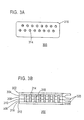
- An exemplary electrode array 100 is depicted in Figure 1.
- the electrode array 100 has 16 electrodes 106, arranged in two rows, which are offset with respect to one another.
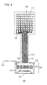
- Another electrode array 400 is depicted in Figure 4.
- Electrode array 400 has 64 electrodes 106, arranged in eight rows and eight columns. Surfaces (not shown) of electrodes 106 are exposed through a non-conductive sheet (not shown) facing the skin surface (view not shown).
- the nonconductive sheet is advantageously a polyimide, however the composition of the nonconductive sheet need not be limited to this material.
- suitable nonconductive sheet materials include polycarbonates, polyurethanes, polyvinylchlorides, polybutylenes, vinyl, silastic, and polyethylene.
- the electrodes 106 are advantageously fabricated using a subtraction technique for production of printed circuit boards.
- An image of electrodes and traces is first developed on a copper-plated KAPTON® brand (duPont) polyimide polymer sheet.
- a photoresist layer is applied over the image. After exposure to ultraviolet radiation, the copper surrounding the photoresist protected regions is etched away with a ferric chloride solution. The photoresist is removed with an organic solvent, such as acetone.
- nickel is electroplated onto the copper electrode pads. Gold is then electroplated onto the nickel electroplate.
- a final KAPTON® polyimide layer is laminated over the traces. Following soldering of the connector and integrated circuit elements, the electrode assembly is complete.
- the exposed surfaces of electrodes 106 are plated with gold in some examples.
- conductive materials that do not readily react with skin may also be used.
- Such conductive materials include suitable metals, metal alloys, metal-metal salt combinations, and conductive polymers.
- an interposed layer of nickel (not shown) to ensure adequate plating of the gold.
- Other interposed metal layers e.g. tin, may be used.
- the metal paste traces 114 in a Y-configuration provide stability and strength for the electrodes 106.
- the metal paste traces 112 extend from each electrode 106, through a stem 116 of the electrode array 100,400, to attach to the instrumentation connector 122.
- the width and thickness of the metal paste traces 112 vary from 5-15 mil depending on the number of electrodes 106 in the array.
- the metal paste traces 112 may be substituted with metallic inks, metallic wires, or conductive polymers.
- FIG 4 illustrates a second example in which integrated circuit elements are mounted on the instrumentation connector portion 120.
- the electrode array 400 in Figure 4 is illustrated as a 64 electrode two dimensional array, although any number of electrodes may be included in the array.
- the electrode array in Figure 4 is operated by integrated circuit elements consisting of shift registers 470 and multiplexers 472 mounted on the instrumentation connector portion 120 of the electrode array 400.
- shift registers 470 and multiplexers 472 there is one shift register 470 and four multiplexers 472, however other configurations are possible.
- shift registers 470 and multiplexers 472 mounted separately from each other, those of skill in the art will appreciate that they may be fabricated on the same integrated circuit chip.
- additional circuitry such as a control device, may also preferably be included with the shift registers 470 and multiplexers 472.
- the shift registers 470 and multiplexers 472 preferably cause individual electrode elements in the array to provide a sensing signal, such a voltage, in a time division manner according to a predetermined cycling frequency, as understood by those of skill in the art.
- a sensing signal such as a voltage
- the shift registers 470 and multiplexers 472 may be configured to sample the sensing signal from one electrode or from a plurality of electrodes at any given sampling time period.
- the sensing signals provided from the electrodes may then be provided to an analyzing device, such as a nerve location device, through instrumentation connector 122.
- Instrumentation connector 122 may be a plug type connector, or any other known type of electrical connector.
- Figure 8 illustrates the electrode array 100 joined with the sensor attachment system 300 and mounted on the skin of a subject 700.
- the electrode array is connected to an analyzing device 500 via instrumentation connector 122.
- the analyzing device 500 preferably drives a display device 600 to display the results of the analysis performed by the analyzing device 500.
- the analyzing device 500 may be a nerve location device, which determines the location of nerves based on the signals received from the electrode array 100, as described in commonly owned U.S. Patent No. 5,560,372 to Cory.
- the analyzing device 500 is not limited to a nerve location device, and may be any device configured to receive electrical sensing signals from a test organism.
- the analyzing device 500 and the display device 600 may be collectively referred to as a medical imaging instrument.
- the electrode arrays 100,400 are wide at both the electrode sensor region 130 and the instrumentation connector region 120. Between the instrumentation connector region 120 and the electrode sensor region 130, the stem region 116 is narrow to promote flexibility and convenience of use.
- the electrode sensor region 130 of the electrode array 100 preferably contains a registration hole 126 and a registration notch 128. These design characteristics allow for accurate positioning with the sensor attachment system 300.
- a tab 162 is on one side of the electrode sensor portion 130 of the electrode array 100 for ease of removal of the electrode array 100 from a skin marking guide 308 (Fig. 3B) after sampling is complete.
- the electrode arrays 100,400 may have one registration hole 126 and registration notch 128.
- the number and position of the registration notches 128 and registration holes 126 may vary, depending upon the dimensions of the sensor portion 130 of the electrode array 100,400. Some larger two-dimensional electrode arrays employ additional registration elements. Others require no registration notches 128 or registration holes 126.
- the instrumentation connector portion 120 of the electrode array 100,400 preferably has a plastic rigidizer 138 (which may be made of any suitable material other than plastic) positioned on the side of the electrode array opposite the exposed electrodes.
- the rigidizer 138 provides additional support for the instrumentation connector 122 and any attached integrated circuit elements such as shift registers 470 and multiplexers 472.
- a return lead 134 connects via a soldered union 136 to a metal trace 132 running to the instrumentation connector 122.
- the instrumentation connector portion 120 of the electrode array 100, 400 is encapsulated in molded medicinal grade silicone polymer of polyethylene. Metal paste material may be applied at points of curvature and stress on the electrode array 100, 400 to provide additional shear-resistance and prolong the useable life span of the electrode array.
- Figure 2 depicts a side cross-sectional view of the electrical components of the example depicted in Figure 1.
- instrumentation connector 122 Within the instrumentation connector region 120 is instrumentation connector 122, which connects to metal paste traces 112.
- the return electrode wire(s) 134 are connected to instrumentation connector 122 though metal past trace 132 at soldered union 136.
- the metal paste traces 112 connect to the electrode sensor region 130.
- the electrode array of the invention is preferably used in combination with a skin sensor attachment system as described herein.
- the electrode array can also be used independently of the skin sensor attachment system, for example, as a diagnostic device to screen peripheral nerves for abnormalities.
- FIG. 3A and 3B An embodiment of a sensor attachment system 300 for use with an electrode array 100 as depicted in Figure 1 is depicted in Figures 3A and 3B.
- Sensor attachment system 300 is shaped to conform exactly to a particular electrode array configuration such as electrode array 100 in Figure 1.
- a suitable sensor attachment system 300 according to the present invention consists of seven layers.
- Holes 314 are formed through all layers of the sensor attachment system 300 except for the top cover 302 and the bottom cover 312.
- the holes 314 are filled with a conductive material 318 comprising, but not limited in composition to, an organic hydrogel.
- Registration elements are preferably positioned on the sensor attachment system to provide for accurate placement of the electrode array 100 on the sensor attachment system 300 and to indicate orientation on the nerve location device display.
- Tabs 320 aligned with the electrode array tab 162 of e ectrode array 100, are found on the support layer 306 and the skin marking guide 308. The tabs 320 aid in removal of the support layer 306 and skin marking guide 308.
- the sensor attachment system 300 may be packaged in a rigid container or aluminized pouch (not shown) which is sealed in an airtight fashion.
- the sensor attachment system 300 in its container, is preferably capable of withstanding sterilization by gamma-irradiation.
- the sensor attachment system 300 In its sealed container, the sensor attachment system 300 preferably has a shelf life of approximately 18 months.
- FIG. 5A A combination of sensor attachment system 300 and electrode array 100 is shown in Figures 5A and 5B.
- sensor attachment system 300 is applied to electrode sensor region 130 of electrode array 100.
- the electrode array 100 and sensor attachment system 300 are seen from the side facing the skin during attachment.
- the sensor attachment system 300 is seen after bottom cover 312 has been peeled off Visible are registration notch 128, registration hole 126, tab 162, conductor islands 314 and adhesive layer 316, which covers skin marking guide 308.
- Return lead 134 connects to instrumentation connector region 120, which has an instrumentation connector 122 for connection to an appropriate instrument.
- An electrode array and sensor attachment system when connected to an appropriate nerve location device, may be used to identify peripheral nerves, neuromas, myofascial trigger points, nerve entrapments, and acupuncture points.
- one preferably attaches the sensor attachment system 300 to an appropriately configured electrode array 100, which is then connected to the nerve location device.
- the electrode array When used for sensing nerves, the electrode array may preferably operate in the same manner as the electrode array described in commonly owned U.S. Pat. No. 5,560,372.
- an input current may be applied to each electrode, then, as shown in Fig. 10(B) an output voltage is sensed from each electrode. The variations in the output voltage received indicate the underlying tissue electrical conductance.
- FIG. 6 depicts an embodiment according to the present invention, wherein the sensor attachment system 300 is then attached to skin 602. Electrode array 100 has been attached to the sensor attachment system 300, from which top layer 302 and bottom layer 312 have been removed.
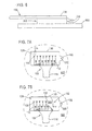
- FIG. 7A A method of using the electrode array 100 and sensor attachment system 300 according to the present invention is depicted in Figures 7A-7D.
- an electrode array 100 is shown as it is attached to skin 602 through a sensor attachment system (not shown).
- the electrode sensor region 130 of the electrode array 100 which comprises electrodes 106, metal paste traces 112 and 114, registration notch 128, registration hole 126 and tab 162.
- the electrode sensor region 130 is attached to the instrumentation connector region (not shown) through stem 116.
- Figure 7B depicts removal of electrode array 100 from skin marking guide 308.
- the support layer 306 goes with electrode array 100 as it is peeled back from the skin marking guide 308 via tab 162.
- Figure 7C depicts marking of skin 602 through a hole 702 in skin marking guide 308 with a pen 710.
- Figure 7D depicts peeling away of skin marking guide 308 from skin 602 to reveal mark 712. Steps for carrying out a method of using an electrode array and sensor attachment system include the following:
Abstract
A system for detecting and marking the positions of peripheral nerves is disclosed. A disposable or reusable electrode array comprising a plurality of electrodes is combined with a disposable sensor attachment system comprising conductor islands. In use, the electrode array is connected to a peripheral nerve detection instrument. The disposable sensor attachment system is attached to an electrode sensor region. The sensor attachment system is then adhered to an area of skin, detection is carried out, and then the electrode array is peeled back from the skin, leaving a skin marking guide in place. The skin marking guide is then used to mark areas of interest to a therapist.

Description
- This invention relates to a medical device for the non-invasive location and imaging of peripheral nerves. Specifically, the present invention relates to a sensor attachment system for use at the skin surface with an electrode array assembly having one or more electrodes. Each electrode in the electrode array assembly maintains a connection to peripheral nerve detection and imaging instrumentation. One or more return wires are attached to the electrode array assembly and to a skin surface electrode during use of the sensor system. A disposable, sterile sensor attachment system allows conductance between the electrode array and the skin surface of the subject. The sensor attachment system contains individual conductor islands, each adapted to align accurately with a specific electrode of the electrode array. The layer of the sensor attachment system that adheres to the skin surface of the subject may be left on the skin at the end of sampling to provide a skin marking guide. This facilitates the positioning of needles for subsequent nerve stimulation or therapy.
- The use of direct current skin surface conductance or resistance measurements has been employed in many forms for the identification of peripheral nerves, myofascial trigger points and acupuncture points (Cory, et al., Characterisation of cutaneous electrical hyperconductivity sites associated with myofascial trigger points and tarsal tunnel syndrome.
- In: Abstracts, 8th World Congress on Pain (Seattle: LASP Press, 1996), p. 54; Kaslow AL and Lowenschuss O. Dragon chasing: a new technique for acupuncture point finding and stimulation. American Journal of Acupunture, 3(2):157-160, 1975); Kejariwal, et al., Development of a device for non-invasive nerve location. In: Abstracts, 8th World Congress on Pain (Seattle: IASP Press, 1996), p.279-280; Kwok, et al., Mapping acupunture points using multi channel device. Australas Phys Eng Sci Med, 21(2):68-72, 1998; Lykken, Square-wave analysis of skin impedance. Psychophysiology, 7(2):262-275, 1971. An early example of this was the use of a transcutaneous electrical nerve stimulation (TENS) unit to identify acupuncture points. When a TENS unit is coupled between examiner and subject, the finger of the examiner acts as a sampling electrode (Kaslow, et al., Dragon chasing: a new technique for acupuncture point finding and stimulation. American Journal of Acupunture, 3(2):157-160, 1975)). However, the literature in the field illustrates inconsistency in locating these sites through electrical conductance measurements (Reichmanis et al., Electrical correlates of acupuncture points. IEEE Transactions on Biomedical Engineering BME 22:533-535, 1975).
- U.S. Pat. No. 4,016,870 to Lock describes a system for acupuncture point location in which a single, hand-held probe of undisclosed composition is used to determine sites of high skin surface conductance. U.S. Pat. No. 5,897,505 to Feinberg, et al., describes a system for measuring selective tissue conductance and temperature utilizing chrome-plated, brass electrodes in a handheld embodiment. Although each of these systems measures conductance at the skin surface, they suffer two main drawbacks. First, metallic electrodes display uneven current densities at the skin surface-electrode interface, which is largely dependent on the underlying moisture pattern of the skin. Devices for measuring skin surface conductance and resistance that do not employ aqueous interfaces are particularly subject to this effect and, in some cases, current densities became high enough to produce a painful sensation. Second, handheld devices are subject to uncontrolled application pressures. This is complicated in larger diameter electrode systems, such as that o. U.S. Patent 5,897,505 to Feinberg, where the angle of application causes pressure to be unequally distributed on the skin surface. The use of electrical conductance measurements at the skin surface to locate nerve tissue is facilitated by the use of aqueous electrodes, rather than metallic or dry silver-silver chloride electrodes, and by the use of non-sinusoidal, alternating current waveforms. Based upon observations such as these, a device that locates peripheral nerves transcutaneously was disclosed in the commonly owned U.S. Pat. No. 5,560,372 to Cory
- FIG. 9 is a circuit diagram of the non-invasive, peripheral nerve mapping device according to the U.S. Pat No. 5,560,372 to Cory as it is positioned over the forearm of a patient. The sampling electrode (10) depicted herein comprises eight electrodes (10a-h) having leads (41) arranged in a linear array and applied to the volar surface of the forearm on the epidermal surface (80). The reference electrode (70) is placed on the dorsal forearm. A constant current output is applied between the two electrodes (10, 70) on the epidermal surface (80). The voltage difference V between the two electrodes is measured and varies from adjacent skin sites as the electrical conductance of the skin changes. The reference electrode (70) may comprise a conductive carbon impregnated silastic pad provided with an insulated metal foil sheet laminated thereto. The metal foil sheet is in electrical contact with a connector element. The reference electrode may further contain adhesive layer laminated to the bottom of the silastic pad provided with a silicon release sheet attached to the adhesive layer. Reference electrode may comprise a carbon-impregnated silastic pad provided with a layer of pharmaceutical electrode gel placed on the bottom of the pad to be positioned against the skin.
- FIG. 10(A) depicts the constant current input (I) for each sub-electrode (10a through 10h), numbers 1-8 respectively, as shown in FIG. 9. FIG. 10(B) depicts the voltage output V for each sub-electrode. With reference to FIG. 9 and FIG. 10(B), electrode number (10b),
number 2 in FIG. 10(B) is positioned over ulnar nerve (88): As shown in FIG. 10(B), electrode (10b) indicates the position of the ulnar nerve (88) by a decrease in output voltage. Similarly, electrodes (10d) and (10e),numbers - The problem of avoiding metallic interfaces with the skin surface is addressed by the use of water-saturated felt electrodes in U.S. Pat. No. 5,560,372 to Cory and by the use of hydrogels (Jossinet and McAdams, Hydrogel Electrodes in Biosignal Recording. Annual International Conference on the IEEE Engineering in Medicine and Biology Society, 12(4): 1490-1491, 1990). The ability to obtain reproducible skin surface conductance and resistance readings allows the recognition of skin surface sites that correspond to underlying peripheral nerves. While this approach circumvents the problems of current density disparities, of the formation of thin oxidation films on the electrodes, and of subsequent back electromotive force, additional problems remain that are associated with the interface between the sampling electrodes and the skin surface.
- The invention is defined in the independent claims to which reference should now be made. Advantages features are set forth in the appendent claims.
- According to a preferred embodiment of the invention, there is provided a sensor attachment system for attaching an electrode array to the skin, comprising: a skin marking guide layer having at least one marking hole therein; a support layer having one conductor island hole corresponding to each marking hole in the skin marking guide layer, each said conductor island hole containing a conductor island which projects into its corresponding marking hole; wherein the skin marking guide layer and the support layer are detachably affixed one to the other.
-
- FIG. 1 is a basic depiction of an electrode array in a 16-electrode conformation, in a view from the side not facing the skin (top view).
- FIG. 2 is a cross-sectional side view of an electrode array in a 16-electrode conformation.
- FIG. 3A shows a sensor attachment system in a 16-electrode conformation, in a top view.
- FIG. 3B shows a sensor attachment system in a 16-electrode conformation, in a side view.
- FIG. 4 shows an exemplary electrode array in a 64-electrode conformation, in a top view.
- FIG. 5A shows an assembly of an electrode array and a sensor attachment system in a side view.
- FIG. 5B shows an assembly of an electrode array and sensor attachment system of FIG. 5A view from the sensor attachment side.
- FIG. 6 shows a side view of an electrode array and sensor attachment system according to the present invention attached to an area of skin.
- FIG. 7A-7D illustrate the steps of removing an electrode array from a skin marking guide, marking a location on an area of skin through a hole in the skin marking guide, and removal of the skin marking guide from the area of skin.
- FIG. 8 illustrates the use of the electrode array and sensor attachment system with an electronic measurement device, such as a nerve mapping device.
- FIG. 9 illustrates a prior art embodiment of an array sensor in a nerve mapping device.
- FIGs. 10A and 10B illustrate a prior art operation of an array sensor to sense various types of nerves in a nerve mapping device.
- A preferred sensor system comprises an electrode array and a sensor attachment system to attach to the skin. When combined to form the sensor system, both the electrode array and the sensor attachment system are presented in the form of complementary arrays of electrodes and conductor islands, respectively. The electrode array comprises one or more electrodes, advantageously four or more electrodes. The electrodes may be arranged randomly, in a single line, or in another fixed order. Advantageously, the electrodes of the array may be arranged in plural rows. The adjacent rows may be in line with one another or offset with respect to their nearest neighbour(s). A preferred arrangement is for the array to comprise a minimum of four electrodes arranged as two or more rows, where adjacent rows are in line with one another. Another preferred arrangement is for the array to comprise a minimum of four electrodes arranged as two or more rows of electrodes, where adjacent rows are offset with respect to one another.
- A further preferred arrangement is for there to be a minimum of two rows of four or more electrodes each.
- A further preferred arrangement is for there to be a minimum of two rows of eight or more electrodes each.
- Another further preferred arrangement is for there to be a minimum of eight rows of eight electrodes each.
- An exemplary embodiment is a two row array, as depicted in FIG 1, where an offset arrangement of adjacent rows is used. Another exemplary embodiment is an eight row arrangement, as depicted in FIG. 4, where adjacent rows are in line with one another.
- By the foregoing, it should be apparent that any number of conformations is possible. What electrode array assemblies of all of the described examples have in common is that the electrodes of the electrode array line up with the conductor islands of the sensor attachment system so that they can operate together as the herein described sensor system.
- An electrode array assembly may advantageously be made flexible so that the electrode array assembly may conform to a wide variety of body surfaces, locations and circumferences. To achieve this flexibility, the electrode array should comprise as a support structure a flexible, electrically non-conductive sheet. Also, it is useful to employ very thin, narrow, electrically conductive paste or adhesive as an electrical connection between the electrodes in the electrode array region and the leads in the electrical connector region of the electrode array. The electrical connections may also comprise suitably applied metallic ink, metallic wire, or conductive trace.
- The electrode array may be reused, a feature which is particularly achieved when the electrode array is used with a separate sensor attachment system.
- The electrode surface should be chemically, as well as biologically, inert. In other words, the electrode surface should not chemically react with, or be degraded by, surfaces which it will contact during normal use. To obtain reproducible measurements, the formation of thin, oxidation films on the electrode surface must be avoided. At the same time, the electrode array must be resistant to damage by bending and twisting. The electrode array must also be stable when cleaned with common sterilizing agents, such as isopropyl alcohol. The electrode array must also be stable upon sterilization by ethylene oxide, gamma radiation, or autoclaving. Suitable materials for the electrode surfaces include gold, gold-plated copper, nickel-plated metal, platinum, palladium, silver-silver chloride or another conductive metal, metal salt combination or conductive polymer(s) such as polyaniline.
- In preparing the electrode array assemblies, thought must be given to the reduction of sampling error. The present inventors have performed experiments to determine the size parameters that minimize sampling error. The preferred arrays may be advantageously practiced by constructing electrode arrays in which the electrode diameters are in the range of about 2-3 mm, with edge-to-edge spacing of about 3 mm. Smaller electrode diameters and closer electrode spacing may result in excessive variation between sample readings. It is believed that, at smaller electrode diameters, conductor resistance increases due to decreasing cross-sectional area in relation to the electrical field path, which may introduce variation in sample readings. However, where such variations are tolerable, smaller electrode diameters may be used. Of course, larger electrode diameters and spacings may be advantageously employed, although smaller diameters are generally preferred due to their generally more favorable resolution characteristics. The ordinary artisan will appreciate that a wide variety of electrode diameters and spacings may be used.
- The sensor attachment system provides an interface between the electrode array and the skin surface of a living being, preferably a mammal, more preferably a human patient. The sensor attachment system comprises a plurality of layers. One layer, hereinafter the support layer, contains a plurality of conductor-islands arranged in a support. The conductor-islands are formed from a suitable conductive material such as a hydrogel, or silver-silver chloride gel. Another layer, hereinafter the skin marking guide layer, is fenestrated (i.e. has holes) so that the conductor islands protrude through the holes therein. The support layer and the skin marking guide layer are held together by an adhesive that is easily broken, so that after imaging the peripheral nerves, the practitioner may then peel the support layer away from the skin marking guide layer, leaving the latter attached to the skin.
- The hydrogel or silver-silver chloride gel may be any electrically conductive hydrogel or silver-silver chloride gel known in the medicinal, biofeedback or biological testing arts. The hydrogel polymers are desirably water interactive and/or hydrophilic in nature and are of a molecular weight or structure, or have been modified such that they absorb significant quantities of water and may form hydrogels when placed in contact with water or aqueous media for a period of time sufficient to reach equilibrium with water, but which do not fully dissolve at equilibrium in water.
- The hydrogel polymers include polymers from the group of homo- and copolymers based on various combinations of the following vinyl monomers: acrylic and methacrylic acids, acrylamide, methacrylamide, hydroxyethylacrylate ormethacrylate, vinylpyrrolidones, as well as polyvinyalcohol and its co- and terpolymers, polyvinylacetate, its co- and terpolymers with the above listed monomers and 2-acrylamido-2-methyl-propanesulfonic acid (AMPS®) and sulfonated styrenes. Very useful are copolymers of the above listed monomers with copolymerizable functional monomers such as acryl or methacryl amide acrylate or methacrylate esters where the ester groups are derived from straight or branched chain alkyl, aryl having up to four aromatic rings which may contain alkyl substituents of 1 to 6 carbons. Most preferably the hydrogels of the invention should be composed of synthetic copolymers from the group of acrylic and methacrylic acids, acrylamide, methacrylamide, hydroxyethylacrylate (HEA) or methacrylate (HEMA), vinylpyrrolidones, and polyacrylonitriles. Specific illustrative examples of useful polymers are the following types of polymers: hydroxyethyl methacrylate, crosslinked polyvinyl alcohol, crosslinked N-vinylpyrrolidone/acrylic acid copolymers, crosslinked poly(N-vinyl lactam), crosslinked polyacrylamide, crosslinked polyacrylic acid, and crosslinked poly(2-acrylamide-2-methylpropane) sulfonic acid, or "Procam" or Hydrogel A11926, tradenames of Ludlow Technical Products hydrogel material.
- The foam used in the support layer may be any foam known in the art for such applications. The foam support layer should be flexible so as to conform to the surface to which it is applied. Any type of foam layer may be used but preferred foams are closed cell foams such as polyethylene. Closed cell foams are foams which have generally spherical discrete pores which are not connected. However, equivalent support layers may be used as known in the medical arts.
- The skin marking guide layer may be made of any polymeric material known in the medical arts. Particularly advantageous are those polymeric materials that are clear or translucent. Polyurethane, polypropylene, polyvinyl chloride, and copolymers thereof, all of which are known in the art, are preferred. The polymeric materials may be colored in order to enhance their visibility against skin. Particularly preferred are bright colors that offer enhanced contrast on any colored skin. Color such as blue and white are particularly preferred for the skin marking guide, however other colors, such a fluorescent yellow, orange, green and magenta may also be used.
- The nerve imaging instrument to be employed may be any suitable instrument known in the art, such as the multiplexed system disclosed in commonly owned U.S. Pat. No. 5,560,372 to Cory.
- The following non-limiting advantages may be realized by the preferred system:
- 1. Sterility. The new sensor attachment system directly contacts the skin of the subject and should be a sterile, disposable, adhesive patch. The electrode array, to which the sensor attachment system operatively attaches to the skin, may extend about six inches away from the skin of the subject, may be disposable or may be reusable and cleansed with isopropyl alcohol or sterilized under ethylene oxide, gamma radiation, or autoclaving.
- 2. Skin marking. Once samples have been taken with the sensor, all but the bottom (skin marking guide) layer of the sensor attachment system may be removed from the skin of the subject. This bottom layer is fenestrated, with holes that correspond to the location of the electrodes in the electrode array, and provides a skin marking guide. Skin can be marked through this skin marking guide to facilitate subsequent injection(s) at the site(s) chosen by the practitioner based upon the readings obtained, or the skin marking guide may be left in place on the skin to provide a convenient template for guiding a nerve stimulation needle or other needle.
- 3. Pressure applied to electrodes. The electrode array and sensor attachment system, joined together, are placed on the skin surface before sampling. The joined devices are held on the skin by virtue of an adhesive on the sensor attachment system. This arrangement was designed in part to circumvent the possibility that unequal pressures applied to each of the electrodes by the practitioner would interfere with the readings obtained at sampling.
- 4. Motion artifacts. Stable adherence of the sensor attachment system to the skin of the subject and to the electrode array decreases the possibility of motion artifacts.
- 5. Quality of image. The number of electrodes in the electrode array assembly may be increased in order to improve the resolution possible with the device.
- 6. Flexibility. The sensor attachment system and electrode array may be manufactured with different numbers of electrodes in different arrangements to address multiple uses and user preferences.
- 7. Imaging of a two-dimensional area. To image a two-dimensional area, as required for neurodiagnostic applications of the device, the sensor attachment system and electrode array may be manufactured in a two-dimensional rather than a linear format (for example, an 8x8 array). This circumvents the need to move the device along a line on the skin surface, which is cumbersome for the operator and subject to inaccuracy.
- 8. Parts replacement. The sensor attachment system is disposable after each use, but is designed as a sterile part that is inexpensive to produce. The electrode arrays may be designed as reusable parts, but would be subject to wear and tear during use and sterilization. The preferred embodiment of this invention has the practical advantage of separating the electrode array from the reminder of the device so that the electrode arrays, if nondisposable, may easily be replaced at minimal cost.
- 9. Operator's hands. The new methods and apparatus offer an important practical advantage in freeing up the hands of the practitioner while samples are taken and displayed.
- 10. Acceptability in practice. The preferred embodiment significantly decreases the steps required to sample the skin surface, reducing the time required for nerve localization.
- 11. Size. The bulk of the device that is in proximity to the subject has been reduced significantly, facilitating use of the device and acceptance by the subject.
- 12. Placement of the return electrode(s). The attachment of the return electrode wire(s) of limited length to the electrode array minimizes errors in the placement of the return electrode(s).
- Further uses, benefits and features will be seen from a review of the detailed description of the preferred system in conjunction with the various figures of the drawings.
- An
exemplary electrode array 100 is depicted in Figure 1. - The
electrode array 100 has 16electrodes 106, arranged in two rows, which are offset with respect to one another. Anotherelectrode array 400 is depicted in Figure 4.Electrode array 400 has 64electrodes 106, arranged in eight rows and eight columns. Surfaces (not shown) ofelectrodes 106 are exposed through a non-conductive sheet (not shown) facing the skin surface (view not shown). The nonconductive sheet is advantageously a polyimide, however the composition of the nonconductive sheet need not be limited to this material. Other suitable nonconductive sheet materials include polycarbonates, polyurethanes, polyvinylchlorides, polybutylenes, vinyl, silastic, and polyethylene. - The
electrodes 106 are advantageously fabricated using a subtraction technique for production of printed circuit boards. An image of electrodes and traces is first developed on a copper-plated KAPTON® brand (duPont) polyimide polymer sheet. A photoresist layer is applied over the image. After exposure to ultraviolet radiation, the copper surrounding the photoresist protected regions is etched away with a ferric chloride solution. The photoresist is removed with an organic solvent, such as acetone. Following masking of the copper traces, nickel is electroplated onto the copper electrode pads. Gold is then electroplated onto the nickel electroplate. A final KAPTON® polyimide layer is laminated over the traces. Following soldering of the connector and integrated circuit elements, the electrode assembly is complete. - To ensure non-reactivity with a sensor attachment system 300 (Figs. 3A, 3B) or with a skin layer itself, the exposed surfaces of
electrodes 106 are plated with gold in some examples. - However, other conductive materials that do not readily react with skin may also be used. Such conductive materials include suitable metals, metal alloys, metal-metal salt combinations, and conductive polymers. Between the gold surfaces of
electrodes 106 and underlying metal paste traces 112 is an interposed layer of nickel (not shown) to ensure adequate plating of the gold. Other interposed metal layers, e.g. tin, may be used. Opposite the gold-plated surface of the electrode the metal paste traces 114 in a Y-configuration provide stability and strength for theelectrodes 106. The metal paste traces 112 extend from eachelectrode 106, through astem 116 of the electrode array 100,400, to attach to theinstrumentation connector 122. The width and thickness of the metal paste traces 112 vary from 5-15 mil depending on the number ofelectrodes 106 in the array. The metal paste traces 112 may be substituted with metallic inks, metallic wires, or conductive polymers. - Figure 4 illustrates a second example in which integrated circuit elements are mounted on the
instrumentation connector portion 120. Theelectrode array 400 in Figure 4 is illustrated as a 64 electrode two dimensional array, although any number of electrodes may be included in the array. The electrode array in Figure 4 is operated by integrated circuit elements consisting ofshift registers 470 andmultiplexers 472 mounted on theinstrumentation connector portion 120 of theelectrode array 400. In the example depicted in Figure 4, there is oneshift register 470 and fourmultiplexers 472, however other configurations are possible. Moreover, although the example illustratesshift registers 470 andmultiplexers 472 mounted separately from each other, those of skill in the art will appreciate that they may be fabricated on the same integrated circuit chip. Those of skill in the art will also appreciate that additional circuitry, such as a control device, may also preferably be included with the shift registers 470 andmultiplexers 472. - The shift registers 470 and
multiplexers 472 preferably cause individual electrode elements in the array to provide a sensing signal, such a voltage, in a time division manner according to a predetermined cycling frequency, as understood by those of skill in the art. Moreover, those of skill in the art will appreciate that the shift registers 470 andmultiplexers 472 may be configured to sample the sensing signal from one electrode or from a plurality of electrodes at any given sampling time period. The sensing signals provided from the electrodes may then be provided to an analyzing device, such as a nerve location device, throughinstrumentation connector 122.Instrumentation connector 122 may be a plug type connector, or any other known type of electrical connector. - Figure 8 illustrates the
electrode array 100 joined with thesensor attachment system 300 and mounted on the skin of a subject 700. As illustrated in Figure 8, the electrode array is connected to ananalyzing device 500 viainstrumentation connector 122. The analyzingdevice 500 preferably drives adisplay device 600 to display the results of the analysis performed by the analyzingdevice 500. In the example, the analyzingdevice 500 may be a nerve location device, which determines the location of nerves based on the signals received from theelectrode array 100, as described in commonly owned U.S. Patent No. 5,560,372 to Cory. However, the analyzingdevice 500 is not limited to a nerve location device, and may be any device configured to receive electrical sensing signals from a test organism. The analyzingdevice 500 and thedisplay device 600 may be collectively referred to as a medical imaging instrument. - The electrode arrays 100,400 are wide at both the
electrode sensor region 130 and theinstrumentation connector region 120. Between theinstrumentation connector region 120 and theelectrode sensor region 130, thestem region 116 is narrow to promote flexibility and convenience of use. Theelectrode sensor region 130 of theelectrode array 100 preferably contains aregistration hole 126 and aregistration notch 128. These design characteristics allow for accurate positioning with thesensor attachment system 300. Atab 162 is on one side of theelectrode sensor portion 130 of theelectrode array 100 for ease of removal of theelectrode array 100 from a skin marking guide 308 (Fig. 3B) after sampling is complete. The electrode arrays 100,400 may have oneregistration hole 126 andregistration notch 128. Alternatively, the number and position of theregistration notches 128 andregistration holes 126 may vary, depending upon the dimensions of thesensor portion 130 of the electrode array 100,400. Some larger two-dimensional electrode arrays employ additional registration elements. Others require noregistration notches 128 or registration holes 126. - The
instrumentation connector portion 120 of the electrode array 100,400 preferably has a plastic rigidizer 138 (which may be made of any suitable material other than plastic) positioned on the side of the electrode array opposite the exposed electrodes. Therigidizer 138 provides additional support for theinstrumentation connector 122 and any attached integrated circuit elements such asshift registers 470 andmultiplexers 472. Areturn lead 134 connects via asoldered union 136 to ametal trace 132 running to theinstrumentation connector 122. Theinstrumentation connector portion 120 of theelectrode array electrode array - Figure 2 depicts a side cross-sectional view of the electrical components of the example depicted in Figure 1. Within the
instrumentation connector region 120 isinstrumentation connector 122, which connects to metal paste traces 112. The return electrode wire(s) 134 are connected toinstrumentation connector 122 though metal pasttrace 132 atsoldered union 136. The metal paste traces 112 connect to theelectrode sensor region 130. - The electrode array of the invention is preferably used in combination with a skin sensor attachment system as described herein. However, the electrode array can also be used independently of the skin sensor attachment system, for example, as a diagnostic device to screen peripheral nerves for abnormalities.
- An embodiment of a
sensor attachment system 300 for use with anelectrode array 100 as depicted in Figure 1 is depicted in Figures 3A and 3B.Sensor attachment system 300 is shaped to conform exactly to a particular electrode array configuration such aselectrode array 100 in Figure 1. A suitablesensor attachment system 300 according to the present invention consists of seven layers. - 1.
Top cover 302 of the sensor attachment system 300 i preferably composed of polyethylene, polystyrene, polyvinylchloride, polybutylene, polyurethane or other material and provides protection for the underlying materials. - 2. A top
adhesive layer 304 allows solid connection of thesensor attachment system 300 with theelectrode array 100. In the preferred embodiment, the topadhesive layer 304 does not extend over theconductor islands 314. - 3. Beneath the top
adhesive layer 304 is asupport layer 306 comprised of, but not limited in composition to, closed-cell foam. The thickness of thesupport layer 306 may be varied depending on the application intended. - 4. Between the
support layer 306 and askin marking guide 308 is an intermediateadhesive layer 310, which joins thesupport layer 306 and theskin marking guide 308. - 5. The
skin marking guide 308 is formed of a material such as 4 mil polyethylene, which is preferably colored so as to be easily visible on all skin types (e.g, blue or white). - 6. A
bottom adhesive layer 316 allows theskin marking guide 308, and thus the entire sensor attachment system with theelectrode array 100 on top of it, to adhere to the skin of the subject. Theskin marking guide 308 allows the skin to be marked at site(s) of interest before its removal. - 7.
Bottom cover 312 of thesensor attachment system 300 is preferably composed of polyethylene, polystyrene, polyvinylchloride, polybutylene, polyurethane or other material and provides protection for the underlying materials. -
Holes 314 are formed through all layers of thesensor attachment system 300 except for thetop cover 302 and thebottom cover 312. Theholes 314 are filled with aconductive material 318 comprising, but not limited in composition to, an organic hydrogel. Registration elements are preferably positioned on the sensor attachment system to provide for accurate placement of theelectrode array 100 on thesensor attachment system 300 and to indicate orientation on the nerve location device display.Tabs 320, aligned with theelectrode array tab 162 of e ectrodearray 100, are found on thesupport layer 306 and theskin marking guide 308. Thetabs 320 aid in removal of thesupport layer 306 andskin marking guide 308. In some embodiments, thesensor attachment system 300 may be packaged in a rigid container or aluminized pouch (not shown) which is sealed in an airtight fashion. Thesensor attachment system 300, in its container, is preferably capable of withstanding sterilization by gamma-irradiation. In its sealed container, thesensor attachment system 300 preferably has a shelf life of approximately 18 months. - A combination of
sensor attachment system 300 andelectrode array 100 is shown in Figures 5A and 5B. In Figure 5Asensor attachment system 300 is applied toelectrode sensor region 130 ofelectrode array 100. In Figure 5B, theelectrode array 100 andsensor attachment system 300 are seen from the side facing the skin during attachment. Thesensor attachment system 300 is seen afterbottom cover 312 has been peeled off Visible areregistration notch 128,registration hole 126,tab 162,conductor islands 314 andadhesive layer 316, which coversskin marking guide 308.Return lead 134 connects toinstrumentation connector region 120, which has aninstrumentation connector 122 for connection to an appropriate instrument. - An electrode array and sensor attachment system according to the present invention, when connected to an appropriate nerve location device, may be used to identify peripheral nerves, neuromas, myofascial trigger points, nerve entrapments, and acupuncture points. To use the invention, one preferably attaches the
sensor attachment system 300 to an appropriately configuredelectrode array 100, which is then connected to the nerve location device. When used for sensing nerves, the electrode array may preferably operate in the same manner as the electrode array described in commonly owned U.S. Pat. No. 5,560,372. Particularly, with reference to Fig. 10(A), an input current may be applied to each electrode, then, as shown in Fig. 10(B) an output voltage is sensed from each electrode. The variations in the output voltage received indicate the underlying tissue electrical conductance. - Figure 6 depicts an embodiment according to the present invention, wherein the
sensor attachment system 300 is then attached toskin 602.Electrode array 100 has been attached to thesensor attachment system 300, from whichtop layer 302 andbottom layer 312 have been removed. - A method of using the
electrode array 100 andsensor attachment system 300 according to the present invention is depicted in Figures 7A-7D. In Figure 7A, anelectrode array 100 is shown as it is attached toskin 602 through a sensor attachment system (not shown). Visible in this view is theelectrode sensor region 130 of theelectrode array 100, which compriseselectrodes 106, metal paste traces 112 and 114,registration notch 128,registration hole 126 andtab 162. Theelectrode sensor region 130 is attached to the instrumentation connector region (not shown) throughstem 116. - Figure 7B depicts removal of
electrode array 100 fromskin marking guide 308. Thesupport layer 306 goes withelectrode array 100 as it is peeled back from theskin marking guide 308 viatab 162. - Figure 7C depicts marking of
skin 602 through ahole 702 inskin marking guide 308 with apen 710. - Figure 7D depicts peeling away of
skin marking guide 308 fromskin 602 to revealmark 712. Steps for carrying out a method of using an electrode array and sensor attachment system include the following: - 1. Connect the
electrode array 100 to an instrumentation connector (not shown) of a nerve location device. - 2. Remove the
top cover 302 from the electrode array side of thesensor attachment system 300. - 3. Align the registration features of
sensor attachment system 300 with theregistration notch 128 and theregistration hole 126 ofelectrode array 100, position and securely attach thesensor attachment system 300 to theelectrode array 100. - 4. Remove
bottom cover 312 from skin surface side of thesensor attachment system 300. - 5. Attach the
skin marking guide 308, now on the combined electrode array and sensor attachment system, to intact skin of a suitable subject. The skin is advantageously prepared by stripping 3-5 times with adhesive tape. - 6. Attach the return electrode(s) (for example, a standard ECG electrode) (not shown) to the skin of subject within 10-20 cm of the
electrode array assembly 100. - 7. Attach the return electrode wire(s) 134, for instance with an alligator clip, to the return electrode(s) of the instrument (not shown).
- 8. Obtain samples with the nerve location instrument (not shown).
- 9. Once skin surface has been sampled with the nerve location device, there are two options:
- a. Using the
tab 162 on theelectrode array 100 and the tab(s) 320 on thesensor attachment system 300, remove theentire electrode array 100 and thesensor attachment system 300 from skin surface, or - b. Using the
tabs 320 on thesensor attachment system 300 as an aid, remove all but theskin marking guide 308 from the skin surface. At this point, one may mark the skin through theskin marking guide 308 at the point(s) of interest determined by the nerve location device. Once the skin surface has been marked, theskin marking guide 308 is removed and the skin surface prepared for positioning of a nerve stimulation needle and/or a needle for therapeutic injection (e.g., regional anaesthesia or pain relief).
- a. Using the
- 10. All portions of the
sensor attachment system 300 are discarded. - 11. The
electrode array 100 is discarded, if in a disposable embodiment, or if in a reusable embodiment, is cleansed with isopropyl alcohol or, if desired, may be sterilised under ethylene oxide, gamma radiation, or autoclaving. The latter method may decrease the longevity of the electrode array. - While the foregoing preferred embodiments serve to illustrate the present invention and the best mode of operation thereof, other suitable embodiments, arrangements and uses may be envisioned by the ordinary artisan and as such are contemplated as being within the scope of the herein described invention, defined by the appended claims.
Claims (5)
- A sensor attachment system (300) for attaching an electrode array to the skin, comprising:a skin marking guide layer (308), having at least one marking hole (702) therein;a support layer (306) having one conductor island hole corresponding to each marking hole in the skin marking guide layer, each said conductor island hole containing a conductor island (314), which projects into its corresponding marking hole;wherein the skin marking guide layer and the support layer are detachably affixed one to the other.
- The sensor attachment system of claim 1, wherein each of said conductor islands comprises a hydrophilic, conductive material (318).
- The sensor attachment system (300) of claim 1 or 2, wherein the conductor island (314) comprises a hydrogel, or a silver-silver chloride gel.
- The sensor attachment system (300) of claim 1, 2 or 3, further comprising a top cover layer (302) adjacent to the top of the support layer (306), and a bottom cover layer (312) adjacent the fenestrated skin marking guide (308);
the top cover layer being detachably affixed to the support layer; and the bottom cover being detachably affixed to the skin marking guide layer;
such that the top cover layer and the bottom cover layer may be removed from the sensor attachment system prior to using the sensor attachment system for imaging peripheral nerves. - The sensor attachment system of any of claims 1 to 4, comprising at least one registration feature (126, 128) for alignment of the sensor attachment system with the electrode array.
Applications Claiming Priority (2)
| Application Number | Priority Date | Filing Date | Title |
|---|---|---|---|
| US09/624,397 US6564079B1 (en) | 2000-07-27 | 2000-07-27 | Electrode array and skin attachment system for noninvasive nerve location and imaging device |
| EP01959192A EP1315449B1 (en) | 2000-07-27 | 2001-07-26 | Electrode array and sensor attachment system for noninvasive nerve location and imaging device |
Related Parent Applications (1)
| Application Number | Title | Priority Date | Filing Date |
|---|---|---|---|
| EP01959192A Division EP1315449B1 (en) | 2000-07-27 | 2001-07-26 | Electrode array and sensor attachment system for noninvasive nerve location and imaging device |
Publications (1)
| Publication Number | Publication Date |
|---|---|
| EP1629768A2 true EP1629768A2 (en) | 2006-03-01 |
Family
ID=24501843
Family Applications (2)
| Application Number | Title | Priority Date | Filing Date |
|---|---|---|---|
| EP05076748A Withdrawn EP1629768A2 (en) | 2000-07-27 | 2001-07-26 | Sensor attachment system for an electrode array |
| EP01959192A Expired - Lifetime EP1315449B1 (en) | 2000-07-27 | 2001-07-26 | Electrode array and sensor attachment system for noninvasive nerve location and imaging device |
Family Applications After (1)
| Application Number | Title | Priority Date | Filing Date |
|---|---|---|---|
| EP01959192A Expired - Lifetime EP1315449B1 (en) | 2000-07-27 | 2001-07-26 | Electrode array and sensor attachment system for noninvasive nerve location and imaging device |
Country Status (9)
| Country | Link |
|---|---|
| US (2) | US6564079B1 (en) |
| EP (2) | EP1629768A2 (en) |
| JP (1) | JP2004504877A (en) |
| AT (1) | ATE306214T1 (en) |
| AU (2) | AU2001280776B2 (en) |
| CA (1) | CA2416146A1 (en) |
| DE (1) | DE60114031T2 (en) |
| WO (1) | WO2002009584A1 (en) |
| ZA (1) | ZA200210239B (en) |
Cited By (2)
| Publication number | Priority date | Publication date | Assignee | Title |
|---|---|---|---|---|
| JP2015529113A (en) * | 2012-09-04 | 2015-10-05 | エルケーシー テクノロジーズ インコーポレイテッド | Electrode array |
| EP3432778A4 (en) * | 2016-03-21 | 2019-11-06 | Assessx Technology Ltd. | An apparatus and method to locate, measure, monitor, and treat inflammation of the skin's soft tissue and fascia layers |
Families Citing this family (229)
| Publication number | Priority date | Publication date | Assignee | Title |
|---|---|---|---|---|
| US20020180605A1 (en) * | 1997-11-11 | 2002-12-05 | Ozguz Volkan H. | Wearable biomonitor with flexible thinned integrated circuit |
| US7786562B2 (en) * | 1997-11-11 | 2010-08-31 | Volkan Ozguz | Stackable semiconductor chip layer comprising prefabricated trench interconnect vias |
| US7003336B2 (en) * | 2000-02-10 | 2006-02-21 | Medtronic Minimed, Inc. | Analyte sensor method of making the same |
| US6564079B1 (en) * | 2000-07-27 | 2003-05-13 | Ckm Diagnostics, Inc. | Electrode array and skin attachment system for noninvasive nerve location and imaging device |
| US20030009111A1 (en) * | 2001-06-13 | 2003-01-09 | Cory Philip C. | Non-invasive method and apparatus for tissue detection |
| US6823212B2 (en) * | 2001-06-13 | 2004-11-23 | The Procter & Gamble Company | Method and apparatus for measuring properties of a target surface |
| US7407570B2 (en) * | 2002-03-13 | 2008-08-05 | The Charles Stark Draper Laboratory, Inc. | Disposable, self-administered electrolyte test |
| US20040061232A1 (en) * | 2002-09-27 | 2004-04-01 | Medtronic Minimed, Inc. | Multilayer substrate |
| US8003513B2 (en) * | 2002-09-27 | 2011-08-23 | Medtronic Minimed, Inc. | Multilayer circuit devices and manufacturing methods using electroplated sacrificial structures |
| AU2003297730A1 (en) * | 2002-12-11 | 2004-06-30 | Mcw Research Foundation, Inc. | Transcutaneous electrical nerve locator |
| US8014878B2 (en) * | 2005-04-28 | 2011-09-06 | Second Sight Medical Products, Inc. | Flexible circuit electrode array |
| US7104965B1 (en) | 2003-06-06 | 2006-09-12 | The General Hospital Corporation | Interactive system and method for peripheral nerve mapping and blocking |
| US20040254494A1 (en) * | 2003-06-11 | 2004-12-16 | Spokoyny Eleonora S. | Method and appartaus for use in nerve conduction studies |
| DE10326402A1 (en) | 2003-06-12 | 2004-12-30 | Antea Medizintechnik + Informationstechnik Gmbh | Electrode sensor system, in particular for recording an electrocardiogram |
| US8419728B2 (en) * | 2003-06-30 | 2013-04-16 | Depuy Products, Inc. | Surgical scalpel and system particularly for use in a transverse carpal ligament surgical procedure |
| US8466243B2 (en) | 2003-07-11 | 2013-06-18 | Sekisui Specialty Chemicals America, Llc | Vinyl alcohol copolymers for use in aqueous dispersions and melt extruded articles |
| US6818709B1 (en) * | 2003-07-11 | 2004-11-16 | Celanese International Corporation | Production of vinyl alcohol copolymers |
| GB0402569D0 (en) * | 2004-02-05 | 2004-03-10 | Neurodan As | Nerve and/or muscle stimulation electrodes |
| US20050181341A1 (en) * | 2004-02-12 | 2005-08-18 | Ewing Donald P. | Self-contained electronic musculoskeletal stimulation apparatus and method of use |
| US8078284B2 (en) * | 2004-05-25 | 2011-12-13 | Second Sight Medical Products, Inc. | Retinal prosthesis with a new configuration |
| GB2414407B (en) * | 2004-05-28 | 2009-04-15 | Eumedic Ltd | Treatment apparatus for applying electrical impulses to the body of a patient |
| CN100395544C (en) * | 2004-08-02 | 2008-06-18 | 大金工业株式会社 | Oxygen electrodes |
| US7465114B2 (en) * | 2004-08-11 | 2008-12-16 | Elc Management Llc | Vibrating mascara applicator, suitable compositions and method of use |
| US7578819B2 (en) | 2005-05-16 | 2009-08-25 | Baxano, Inc. | Spinal access and neural localization |
| US8221397B2 (en) | 2004-10-15 | 2012-07-17 | Baxano, Inc. | Devices and methods for tissue modification |
| US8062300B2 (en) | 2006-05-04 | 2011-11-22 | Baxano, Inc. | Tissue removal with at least partially flexible devices |
| US7887538B2 (en) | 2005-10-15 | 2011-02-15 | Baxano, Inc. | Methods and apparatus for tissue modification |
| US7738969B2 (en) | 2004-10-15 | 2010-06-15 | Baxano, Inc. | Devices and methods for selective surgical removal of tissue |
| AU2005295589B2 (en) | 2004-10-15 | 2009-12-03 | Baxano, Inc. | Devices and methods for tissue removal |
| US20110190772A1 (en) | 2004-10-15 | 2011-08-04 | Vahid Saadat | Powered tissue modification devices and methods |
| US7738968B2 (en) | 2004-10-15 | 2010-06-15 | Baxano, Inc. | Devices and methods for selective surgical removal of tissue |
| US9247952B2 (en) | 2004-10-15 | 2016-02-02 | Amendia, Inc. | Devices and methods for tissue access |
| US8257356B2 (en) | 2004-10-15 | 2012-09-04 | Baxano, Inc. | Guidewire exchange systems to treat spinal stenosis |
| US8048080B2 (en) | 2004-10-15 | 2011-11-01 | Baxano, Inc. | Flexible tissue rasp |
| US8617163B2 (en) | 2004-10-15 | 2013-12-31 | Baxano Surgical, Inc. | Methods, systems and devices for carpal tunnel release |
| US7938830B2 (en) | 2004-10-15 | 2011-05-10 | Baxano, Inc. | Powered tissue modification devices and methods |
| US20100331883A1 (en) | 2004-10-15 | 2010-12-30 | Schmitz Gregory P | Access and tissue modification systems and methods |
| US8430881B2 (en) | 2004-10-15 | 2013-04-30 | Baxano, Inc. | Mechanical tissue modification devices and methods |
| US9101386B2 (en) | 2004-10-15 | 2015-08-11 | Amendia, Inc. | Devices and methods for treating tissue |
| US7959577B2 (en) | 2007-09-06 | 2011-06-14 | Baxano, Inc. | Method, system, and apparatus for neural localization |
| AU2005296341B2 (en) * | 2004-10-19 | 2011-06-30 | Meagan Medical, Inc. | Method and means for electrical stimulation of cutaneous sensory receptors |
| US8417352B2 (en) * | 2004-10-19 | 2013-04-09 | Meagan Medical, Inc. | System and method for stimulating sensory nerves |
| US20060085048A1 (en) * | 2004-10-20 | 2006-04-20 | Nervonix, Inc. | Algorithms for an active electrode, bioimpedance-based tissue discrimination system |
| US7865236B2 (en) * | 2004-10-20 | 2011-01-04 | Nervonix, Inc. | Active electrode, bio-impedance based, tissue discrimination system and methods of use |
| WO2006079888A1 (en) * | 2005-01-31 | 2006-08-03 | Koninklijke Philips Electronics, N.V. | Multi-conductor connection device for a medical sensor |
| US7878981B2 (en) | 2005-03-01 | 2011-02-01 | Checkpoint Surgical, Llc | Systems and methods for intra-operative stimulation |
| US7896815B2 (en) * | 2005-03-01 | 2011-03-01 | Checkpoint Surgical, Llc | Systems and methods for intra-operative stimulation |
| US20110060242A1 (en) * | 2005-03-01 | 2011-03-10 | Checkpoint Surgical, Llc | Systems and methods for intra-operative stimulation within a surgical field |
| US20060200219A1 (en) * | 2005-03-01 | 2006-09-07 | Ndi Medical, Llc | Systems and methods for differentiating and/or identifying tissue regions innervated by targeted nerves for diagnostic and/or therapeutic purposes |
| US20110060238A1 (en) * | 2005-03-01 | 2011-03-10 | Checkpoint Surgical, Llc | Systems and methods for intra-operative physiological functional stimulation |
| US10154792B2 (en) | 2005-03-01 | 2018-12-18 | Checkpoint Surgical, Inc. | Stimulation device adapter |
| US20110060243A1 (en) * | 2005-03-01 | 2011-03-10 | Checkpoint Surgical, Llc | Systems and methods for intra-operative regional neural stimulation |
| US20110054346A1 (en) * | 2005-03-01 | 2011-03-03 | Checkpoint Surgical, Llc | Systems and methods for Intra-operative semi-quantitative threshold neural response testing related applications |
| US8802183B2 (en) | 2005-04-28 | 2014-08-12 | Proteus Digital Health, Inc. | Communication system with enhanced partial power source and method of manufacturing same |
| CN103259027A (en) | 2005-04-28 | 2013-08-21 | 普罗透斯数字保健公司 | Pharma-informatics system |
| US8912908B2 (en) | 2005-04-28 | 2014-12-16 | Proteus Digital Health, Inc. | Communication system with remote activation |
| US8836513B2 (en) | 2006-04-28 | 2014-09-16 | Proteus Digital Health, Inc. | Communication system incorporated in an ingestible product |
| US8730031B2 (en) | 2005-04-28 | 2014-05-20 | Proteus Digital Health, Inc. | Communication system using an implantable device |
| US9198608B2 (en) | 2005-04-28 | 2015-12-01 | Proteus Digital Health, Inc. | Communication system incorporated in a container |
| ATE473679T1 (en) * | 2005-05-31 | 2010-07-15 | Koninkl Philips Electronics Nv | METHOD AND DEVICE FOR INDUCTIVELY MEASURING THE BIOIMPEDANCE OF A USER'S BODY |
| US20110054343A1 (en) | 2005-07-01 | 2011-03-03 | Impedimed Limited | Monitoring system |
| EP2449964B1 (en) | 2005-07-01 | 2016-08-10 | Impedimed Limited | Connector for Impedance Measurement System |
| US20070027387A1 (en) * | 2005-07-28 | 2007-02-01 | Neurometrix, Inc. | Integrated carrier for providing support, templates and instructions for biopotential electrode array |
| US8547248B2 (en) | 2005-09-01 | 2013-10-01 | Proteus Digital Health, Inc. | Implantable zero-wire communications system |
| WO2007041783A1 (en) | 2005-10-11 | 2007-04-19 | Impedance Cardiology Systems, Inc. | Hydration status monitoring |
| US8092456B2 (en) | 2005-10-15 | 2012-01-10 | Baxano, Inc. | Multiple pathways for spinal nerve root decompression from a single access point |
| US20080086034A1 (en) | 2006-08-29 | 2008-04-10 | Baxano, Inc. | Tissue Access Guidewire System and Method |
| US8366712B2 (en) | 2005-10-15 | 2013-02-05 | Baxano, Inc. | Multiple pathways for spinal nerve root decompression from a single access point |
| US8062298B2 (en) | 2005-10-15 | 2011-11-22 | Baxano, Inc. | Flexible tissue removal devices and methods |
| US7877866B1 (en) | 2005-10-26 | 2011-02-01 | Second Sight Medical Products, Inc. | Flexible circuit electrode array and method of manufacturing the same |
| US7914842B1 (en) | 2006-02-10 | 2011-03-29 | Second Sight Medical Products, Inc | Method of manufacturing a flexible circuit electrode array |
| CN105468895A (en) | 2006-05-02 | 2016-04-06 | 普罗透斯数字保健公司 | Patient customized therapeutic regimens |
| US7616980B2 (en) * | 2006-05-08 | 2009-11-10 | Tyco Healthcare Group Lp | Radial electrode array |
| US8200341B2 (en) * | 2007-02-07 | 2012-06-12 | Cameron Health, Inc. | Sensing vector selection in a cardiac stimulus device with postural assessment |
| WO2007138595A2 (en) | 2006-05-31 | 2007-12-06 | Michael Naroditsky | Transcutaneous electrical therapeutic device |
| US9630003B2 (en) * | 2006-06-15 | 2017-04-25 | Htk Enterprises, Inc. | Non-invasive neuro stimulation system |
| US20070293917A1 (en) * | 2006-06-15 | 2007-12-20 | Thompson Thomas C | Non-invasive neuro stimulation system |
| US8204575B2 (en) * | 2006-08-11 | 2012-06-19 | Medtronic, Inc. | Locating guide |
| US9439581B2 (en) * | 2006-08-11 | 2016-09-13 | Medtronic, Inc. | Guided medical element implantation |
| US8506502B2 (en) * | 2006-09-16 | 2013-08-13 | Terence Gilhuly | Sensors and sensing for monitoring neuromuscular blockade |
| US8109883B2 (en) | 2006-09-28 | 2012-02-07 | Tyco Healthcare Group Lp | Cable monitoring apparatus |
| US8054140B2 (en) | 2006-10-17 | 2011-11-08 | Proteus Biomedical, Inc. | Low voltage oscillator for medical devices |
| SG175681A1 (en) | 2006-10-25 | 2011-11-28 | Proteus Biomedical Inc | Controlled activation ingestible identifier |
| EP2069004A4 (en) | 2006-11-20 | 2014-07-09 | Proteus Digital Health Inc | Active signal processing personal health signal receivers |
| US8180425B2 (en) * | 2006-12-05 | 2012-05-15 | Tyco Healthcare Group Lp | ECG lead wire organizer and dispenser |
| US8668651B2 (en) | 2006-12-05 | 2014-03-11 | Covidien Lp | ECG lead set and ECG adapter system |
| US8238996B2 (en) | 2006-12-05 | 2012-08-07 | Tyco Healthcare Group Lp | Electrode array |
| WO2008097407A2 (en) * | 2006-12-18 | 2008-08-14 | Trillium Precision Surgical, Inc. | Intraoperative tissue mapping and dissection systems, devices, methods, and kits |
| US8175718B2 (en) * | 2006-12-19 | 2012-05-08 | Ethicon, Inc. | Electrode patch and method for neurostimulation |
| CN101686800A (en) | 2007-02-01 | 2010-03-31 | 普罗秋斯生物医学公司 | Ingestible event marker systems |
| CA2676280C (en) | 2007-02-14 | 2018-05-22 | Proteus Biomedical, Inc. | In-body power source having high surface area electrode |
| US9138573B2 (en) * | 2007-03-07 | 2015-09-22 | Zoll Medical Corporation | External defibrillators,transcutaneous electrodes for same, and methods of use |
| US9314610B2 (en) * | 2007-03-08 | 2016-04-19 | Zoll Medical Corporation | Defibrillation electrodes |
| EP2063771A1 (en) | 2007-03-09 | 2009-06-03 | Proteus Biomedical, Inc. | In-body device having a deployable antenna |
| EP2124725A1 (en) | 2007-03-09 | 2009-12-02 | Proteus Biomedical, Inc. | In-body device having a multi-directional transmitter |
| CA2684324C (en) | 2007-04-20 | 2017-05-30 | Impedimed Limited | Monitoring system and probe |
| US8083685B2 (en) * | 2007-05-08 | 2011-12-27 | Propep, Llc | System and method for laparoscopic nerve detection |
| US8115618B2 (en) | 2007-05-24 | 2012-02-14 | Proteus Biomedical, Inc. | RFID antenna for in-body device |
| WO2008157513A1 (en) * | 2007-06-15 | 2008-12-24 | Baxano, Inc. | Devices and methods for measuring the space around a nerve root |
| AU2008282451B2 (en) * | 2007-07-27 | 2013-09-26 | Second Sight Medical Products | Implantable device for the brain |
| JP5542050B2 (en) | 2007-08-09 | 2014-07-09 | インぺディメッド リミテッド | Impedance measurement method and apparatus |
| DE102007042257A1 (en) | 2007-09-06 | 2009-03-12 | Covidien Ag | Process for the stepwise or continuous production of disposable biomedical electrodes and electrode system formed therefrom |
| EP2192946B1 (en) | 2007-09-25 | 2022-09-14 | Otsuka Pharmaceutical Co., Ltd. | In-body device with virtual dipole signal amplification |
| US20090088652A1 (en) * | 2007-09-28 | 2009-04-02 | Kathleen Tremblay | Physiological sensor placement and signal transmission device |
| WO2009055735A1 (en) * | 2007-10-24 | 2009-04-30 | Second Sight Medical Products, Inc. | Electrode array for even neural pressure having multiple attachment points |
| US8192436B2 (en) | 2007-12-07 | 2012-06-05 | Baxano, Inc. | Tissue modification devices |
| US8038484B2 (en) | 2007-12-11 | 2011-10-18 | Tyco Healthcare Group Lp | ECG electrode connector |
| SG188839A1 (en) | 2008-03-05 | 2013-04-30 | Proteus Digital Health Inc | Multi-mode communication ingestible event markers and systems, and methods of using the same |
| US20090234236A1 (en) * | 2008-03-14 | 2009-09-17 | General Electric Company | Nerve blood flow modulation for imaging nerves |
| US9314253B2 (en) | 2008-07-01 | 2016-04-19 | Amendia, Inc. | Tissue modification devices and methods |
| US8398641B2 (en) | 2008-07-01 | 2013-03-19 | Baxano, Inc. | Tissue modification devices and methods |
| US8409206B2 (en) | 2008-07-01 | 2013-04-02 | Baxano, Inc. | Tissue modification devices and methods |
| US8892210B2 (en) * | 2008-07-02 | 2014-11-18 | Niveus Medical, Inc. | Devices, systems, and methods for automated optimization of energy delivery |
| AU2009268827B2 (en) | 2008-07-08 | 2013-10-24 | Proteus Digital Health, Inc. | Ingestible event marker data framework |
| CA2730732A1 (en) | 2008-07-14 | 2010-01-21 | Baxano, Inc. | Tissue modification devices |
| US8301219B2 (en) * | 2008-07-16 | 2012-10-30 | The General Hospital Corporation | Patient monitoring systems and methods |
| US8540633B2 (en) | 2008-08-13 | 2013-09-24 | Proteus Digital Health, Inc. | Identifier circuits for generating unique identifiable indicators and techniques for producing same |
| GB0817092D0 (en) * | 2008-09-18 | 2008-10-29 | To Be First Ag | Cranial Electrostimulation method equipment and electrode unit |
| AU2009313879B2 (en) | 2008-11-13 | 2011-10-20 | Proteus Digital Health, Inc. | Ingestible therapy activator system and method |
| USD737979S1 (en) | 2008-12-09 | 2015-09-01 | Covidien Lp | ECG electrode connector |
| CN102271578B (en) | 2008-12-11 | 2013-12-04 | 普罗秋斯数字健康公司 | Evaluation of gastrointestinal function using portable electroviscerography systems and methods of using the same |
| US9439566B2 (en) | 2008-12-15 | 2016-09-13 | Proteus Digital Health, Inc. | Re-wearable wireless device |
| US9659423B2 (en) | 2008-12-15 | 2017-05-23 | Proteus Digital Health, Inc. | Personal authentication apparatus system and method |
| TWI424832B (en) * | 2008-12-15 | 2014-02-01 | Proteus Digital Health Inc | Body-associated receiver and method |
| CA2750158A1 (en) | 2009-01-06 | 2010-07-15 | Proteus Biomedical, Inc. | Ingestion-related biofeedback and personalized medical therapy method and system |
| KR20110104079A (en) | 2009-01-06 | 2011-09-21 | 프로테우스 바이오메디컬, 인코포레이티드 | Pharmaceutical dosages delivery system |
| KR101088806B1 (en) * | 2009-01-07 | 2011-12-01 | 주식회사 뉴로바이오시스 | Micro-electrode Array Package using Liquid Crystal Polymer and Manufacturing Method thereof |
| JP5582619B2 (en) | 2009-03-13 | 2014-09-03 | バクサノ,インク. | Flexible nerve position determination device |
| GB2480965B (en) | 2009-03-25 | 2014-10-08 | Proteus Digital Health Inc | Probablistic pharmacokinetic and pharmacodynamic modeling |
| EP3906845A1 (en) | 2009-04-28 | 2021-11-10 | Otsuka Pharmaceutical Co., Ltd. | Highly reliable ingestible event markers |
| EP2432458A4 (en) | 2009-05-12 | 2014-02-12 | Proteus Digital Health Inc | Ingestible event markers comprising an ingestible component |
| US8394102B2 (en) | 2009-06-25 | 2013-03-12 | Baxano, Inc. | Surgical tools for treatment of spinal stenosis |
| GB2471873B (en) * | 2009-07-15 | 2015-09-23 | Wzvi Ltd | Electrical impedance imaging |
| US8558563B2 (en) | 2009-08-21 | 2013-10-15 | Proteus Digital Health, Inc. | Apparatus and method for measuring biochemical parameters |
| US8694080B2 (en) | 2009-10-21 | 2014-04-08 | Covidien Lp | ECG lead system |
| US9615767B2 (en) | 2009-10-26 | 2017-04-11 | Impedimed Limited | Fluid level indicator determination |
| TWI517050B (en) | 2009-11-04 | 2016-01-11 | 普羅托斯數位健康公司 | System for supply chain management |
| US9585593B2 (en) | 2009-11-18 | 2017-03-07 | Chung Shing Fan | Signal distribution for patient-electrode measurements |
| KR100965351B1 (en) * | 2009-11-23 | 2010-06-22 | 박문서 | Apparatus for acupuncturing with measuring impedance in humanbody using electrode apparatus for measuring impedance in humanbody |
| UA109424C2 (en) | 2009-12-02 | 2015-08-25 | PHARMACEUTICAL PRODUCT, PHARMACEUTICAL TABLE WITH ELECTRONIC MARKER AND METHOD OF MANUFACTURING PHARMACEUTICAL TABLETS | |
| JP5841951B2 (en) | 2010-02-01 | 2016-01-13 | プロテウス デジタル ヘルス, インコーポレイテッド | Data collection system |
| DE102010000565A1 (en) * | 2010-02-26 | 2011-09-01 | Technische Universität Ilmenau | Hybrid three-dimensional sensor array, in particular for measuring electrogenic cell arrangements, and measuring arrangement |
| US20110230785A1 (en) * | 2010-03-16 | 2011-09-22 | ProNerve, LLC | Somatosensory Evoked Potential (SSEP) Automated Alert System |
| SG184494A1 (en) | 2010-04-07 | 2012-11-29 | Proteus Biomedical Inc | Miniature ingestible device |
| US10631912B2 (en) | 2010-04-30 | 2020-04-28 | Medtronic Xomed, Inc. | Interface module for use with nerve monitoring and electrosurgery |
| US9743884B2 (en) | 2010-04-30 | 2017-08-29 | J3G Spine, Llc | Devices and methods for nerve mapping |
| TWI557672B (en) | 2010-05-19 | 2016-11-11 | 波提亞斯數位康健公司 | Computer system and computer-implemented method to track medication from manufacturer to a patient, apparatus and method for confirming delivery of medication to a patient, patient interface device |
| CA2746944C (en) | 2010-07-29 | 2018-09-25 | Tyco Healthcare Group Lp | Ecg adapter system and method |
| US20120041332A1 (en) * | 2010-08-11 | 2012-02-16 | Georgiy Lifshits | Device and method for oriental medicine diagnosis and treatment |
| US9017256B2 (en) * | 2010-09-22 | 2015-04-28 | Milieu Institute, Llc | System and method for physiological monitoring |
| BR112013008190A2 (en) | 2010-10-04 | 2017-12-12 | Nervomatrix Ltd | electrode and apparatus |
| US9155503B2 (en) | 2010-10-27 | 2015-10-13 | Cadwell Labs | Apparatus, system, and method for mapping the location of a nerve |
| JP2014504902A (en) | 2010-11-22 | 2014-02-27 | プロテウス デジタル ヘルス, インコーポレイテッド | Ingestible device with medicinal product |
| KR101244816B1 (en) * | 2010-11-23 | 2013-03-18 | 계명대학교 산학협력단 | novel planar small electrode sensor for skin impedence and system using thereof |
| EP2654556B1 (en) | 2010-12-22 | 2018-10-10 | CardioInsight Technologies, Inc. | Multi-layered sensor apparatus |
| DE102011002846A1 (en) | 2011-01-19 | 2012-07-19 | Robert Bosch Gmbh | Data acquisition unit for device for determining movement activities of person in water, is provided with electrode devices with skin-piercing electrodes for detecting of electrical muscle activity of person |
| JP2014514032A (en) | 2011-03-11 | 2014-06-19 | プロテウス デジタル ヘルス, インコーポレイテッド | Wearable personal body-related devices with various physical configurations |
| US20120330376A1 (en) * | 2011-06-27 | 2012-12-27 | Equine OrthoCare, LLC | Systems and methods for making and using electrical stimulation systems for providing therapy to large animals |
| US9756874B2 (en) | 2011-07-11 | 2017-09-12 | Proteus Digital Health, Inc. | Masticable ingestible product and communication system therefor |
| WO2015112603A1 (en) | 2014-01-21 | 2015-07-30 | Proteus Digital Health, Inc. | Masticable ingestible product and communication system therefor |
| EP2734973A4 (en) | 2011-07-21 | 2015-07-01 | Proteus Digital Health Inc | Mobile communication device, system, and method |
| EP2734106B1 (en) | 2011-07-22 | 2019-09-18 | Kpr U.S., Llc | Ecg electrode connector |
| US8634901B2 (en) | 2011-09-30 | 2014-01-21 | Covidien Lp | ECG leadwire system with noise suppression and related methods |
| US9235683B2 (en) | 2011-11-09 | 2016-01-12 | Proteus Digital Health, Inc. | Apparatus, system, and method for managing adherence to a regimen |
| JP2015512658A (en) | 2011-12-14 | 2015-04-30 | インターセクション・メディカル・インコーポレイテッドIntersection Medical,Inc. | Device, system and method for determining relative spatial variation of subsurface resistivity to frequency in tissue |
| US9283371B2 (en) | 2012-02-29 | 2016-03-15 | Thu-Ha Duncan | Electro-stimulation system |
| US9332918B1 (en) * | 2012-05-07 | 2016-05-10 | Jill Buckley | Patient monitoring devices and systems |
| AU2013293234B2 (en) | 2012-07-23 | 2017-08-31 | Otsuka Pharmaceutical Co., Ltd. | Techniques for manufacturing ingestible event markers comprising an ingestible component |
| WO2014062674A1 (en) | 2012-10-18 | 2014-04-24 | Proteus Digital Health, Inc. | Apparatus, system, and method to adaptively optimize power dissipation and broadcast power in a power source for a communication device |
| US9884178B2 (en) * | 2012-12-05 | 2018-02-06 | Battelle Memorial Institute | Neuromuscular stimulation cuff |
| US11149123B2 (en) | 2013-01-29 | 2021-10-19 | Otsuka Pharmaceutical Co., Ltd. | Highly-swellable polymeric films and compositions comprising the same |
| US9962546B2 (en) | 2013-02-21 | 2018-05-08 | Meagan Medical, Inc. | Cutaneous field stimulation with disposable and rechargeable components |
| US9408546B2 (en) | 2013-03-15 | 2016-08-09 | Covidien Lp | Radiolucent ECG electrode system |
| JP6498177B2 (en) | 2013-03-15 | 2019-04-10 | プロテウス デジタル ヘルス, インコーポレイテッド | Identity authentication system and method |
| US11744481B2 (en) | 2013-03-15 | 2023-09-05 | Otsuka Pharmaceutical Co., Ltd. | System, apparatus and methods for data collection and assessing outcomes |
| USD748275S1 (en) | 2013-03-15 | 2016-01-26 | Tesseract Sensors, LLC | Electrode patch array |
| US10098585B2 (en) | 2013-03-15 | 2018-10-16 | Cadwell Laboratories, Inc. | Neuromonitoring systems and methods |
| CN105120742B (en) | 2013-03-15 | 2017-07-28 | 柯惠有限合伙公司 | Electrode connector with conductive component |
| USD771818S1 (en) | 2013-03-15 | 2016-11-15 | Covidien Lp | ECG electrode connector |
| US10175376B2 (en) | 2013-03-15 | 2019-01-08 | Proteus Digital Health, Inc. | Metal detector apparatus, system, and method |
| USD702357S1 (en) | 2013-03-15 | 2014-04-08 | Tesseract Sensors, LLC | Electrode patch array |
| USD702356S1 (en) | 2013-03-15 | 2014-04-08 | Tesseract Sensors, LLC | Electrode patch array |
| AU2014290582B2 (en) | 2013-07-14 | 2017-08-31 | Cardiac Pacemakers, Inc. | Multi-electrode lead with backing for mecho/baroreceptor stimulation |
| US9796576B2 (en) | 2013-08-30 | 2017-10-24 | Proteus Digital Health, Inc. | Container with electronically controlled interlock |
| CA2924815C (en) | 2013-09-20 | 2017-06-20 | Proteus Digital Health, Inc. | Methods, devices and systems for receiving and decoding a signal in the presence of noise using slices and warping |
| WO2015044722A1 (en) | 2013-09-24 | 2015-04-02 | Proteus Digital Health, Inc. | Method and apparatus for use with received electromagnetic signal at a frequency not known exactly in advance |
| US11166672B2 (en) | 2013-10-18 | 2021-11-09 | Atlantic Health System, Inc. | Nerve protecting dissection device |
| US10084880B2 (en) | 2013-11-04 | 2018-09-25 | Proteus Digital Health, Inc. | Social media networking based on physiologic information |
| US9839785B2 (en) | 2013-12-13 | 2017-12-12 | Cardiac Pacemakers, Inc. | Surgical instrument for implanting leads for baroreceptor stimulation therapy |
| US10029091B2 (en) | 2014-02-20 | 2018-07-24 | Cardiac Pacemakers, Inc. | Apparatus for baroreceptor stimulation therapy |
| US20170014043A1 (en) * | 2014-04-30 | 2017-01-19 | Galvanic Limited | Electrodermal Activity Sensor |
| JP6306742B2 (en) * | 2014-06-19 | 2018-04-04 | カーディアック ペースメイカーズ, インコーポレイテッド | Baroreceptor mapping system |
| WO2016009424A1 (en) * | 2014-07-13 | 2016-01-21 | Nibs Neuroscience Technologies Ltd. | Electrode headset grid and use thereof in the non-invasive brain stimulation and monitoring |
| WO2016014444A1 (en) | 2014-07-21 | 2016-01-28 | ProPep Surgical, LLC | System and method for laparoscopic nerve identification, nerve location marking, and nerve location recognition |
| US9572975B2 (en) | 2014-09-02 | 2017-02-21 | Cardiac Pacemakers, Inc. | Paddle leads configured for suture fixation |
| US11064936B2 (en) * | 2014-09-04 | 2021-07-20 | Active4D, Inc. | Shoulder monitoring and treatment system |
| US9616219B2 (en) | 2014-09-16 | 2017-04-11 | Cardiac Pacemakers, Inc. | Paddle leads having asymmetric electrode configurations |
| US9113912B1 (en) | 2015-01-21 | 2015-08-25 | Serene Medical, Inc. | Systems and devices to identify and limit nerve conduction |
| WO2016118752A1 (en) * | 2015-01-21 | 2016-07-28 | Serene Medical, Inc. | Systems and devices to identify and limit nerve conduction |
| EP3253445A4 (en) | 2015-02-03 | 2018-02-21 | Nibs Neuroscience Technologies Ltd. | Early diagnosis and treatment of alzheimer disease and mild cognitive impairment |
| US10433793B1 (en) | 2015-03-27 | 2019-10-08 | Cadwell Laboratories, Inc. | Methods and systems for simultaneous review of brain activity and physical manifestations of users |
| US10437335B2 (en) | 2015-04-14 | 2019-10-08 | John James Daniels | Wearable electronic, multi-sensory, human/machine, human/human interfaces |
| US9861820B2 (en) | 2015-05-13 | 2018-01-09 | Second Sight Medical Products, Inc. | Cortical visual prosthesis |
| US11051543B2 (en) | 2015-07-21 | 2021-07-06 | Otsuka Pharmaceutical Co. Ltd. | Alginate on adhesive bilayer laminate film |
| WO2017090050A1 (en) * | 2015-11-29 | 2017-06-01 | Ramot At Tel-Aviv University Ltd. | Sensing electrode and method of fabricating the same |
| KR102215238B1 (en) | 2016-07-22 | 2021-02-22 | 프로테우스 디지털 헬스, 인코포레이티드 | Electromagnetic sensing and detection of ingestible event markers |
| BR112019003199A2 (en) * | 2016-08-18 | 2019-06-18 | Novocure Ltd | array temperature measurement for tt fields delivery |
| JP6832535B2 (en) * | 2016-09-13 | 2021-02-24 | 国立大学法人大阪大学 | Electrode sheet |
| WO2018081337A1 (en) | 2016-10-26 | 2018-05-03 | Proteus Digital Health, Inc. | Methods for manufacturing capsules with ingestible event markers |
| JP2020516327A (en) | 2016-11-25 | 2020-06-11 | キナプティック・エルエルシー | Haptic human/mechanical interface and wearable electronics methods and apparatus |
| US11241297B2 (en) | 2016-12-12 | 2022-02-08 | Cadwell Laboratories, Inc. | System and method for high density electrode management |
| TWI624248B (en) * | 2017-01-17 | 2018-05-21 | Univ Chang Gung | Nerve injury zone detection board, nerve assessment system and nerve assessment law |
| US9935395B1 (en) | 2017-01-23 | 2018-04-03 | Cadwell Laboratories, Inc. | Mass connection plate for electrical connectors |
| USD821587S1 (en) | 2017-01-26 | 2018-06-26 | Michael J. Vosch | Electrode patch array |
| USD821588S1 (en) | 2017-01-26 | 2018-06-26 | Michael J. Vosch | Electrode patch array |
| USD907213S1 (en) | 2017-09-18 | 2021-01-05 | Dms-Service Llc | Patch with electrode array |
| USD898202S1 (en) | 2017-11-12 | 2020-10-06 | Dms-Service Llc | Patch with electrode array |
| USD886073S1 (en) * | 2018-01-29 | 2020-06-02 | Gigalane Co., Ltd. | Flexible printed circuit board |
| US11517239B2 (en) | 2018-04-05 | 2022-12-06 | Cadwell Laboratories, Inc. | Systems and methods for processing and displaying electromyographic signals |
| US11596337B2 (en) | 2018-04-24 | 2023-03-07 | Cadwell Laboratories, Inc | Methods and systems for operating an intraoperative neurophysiological monitoring system in conjunction with electrocautery procedures |
| US11253182B2 (en) | 2018-05-04 | 2022-02-22 | Cadwell Laboratories, Inc. | Apparatus and method for polyphasic multi-output constant-current and constant-voltage neurophysiological stimulation |
| US11443649B2 (en) | 2018-06-29 | 2022-09-13 | Cadwell Laboratories, Inc. | Neurophysiological monitoring training simulator |
| US11185684B2 (en) | 2018-09-18 | 2021-11-30 | Cadwell Laboratories, Inc. | Minimally invasive two-dimensional grid electrode |
| US11517245B2 (en) | 2018-10-30 | 2022-12-06 | Cadwell Laboratories, Inc. | Method and system for data synchronization |
| US11471087B2 (en) | 2018-11-09 | 2022-10-18 | Cadwell Laboratories, Inc. | Integrity verification system for testing high channel count neuromonitoring recording equipment |
| US11317841B2 (en) | 2018-11-14 | 2022-05-03 | Cadwell Laboratories, Inc. | Method and system for electrode verification |
| US11529107B2 (en) | 2018-11-27 | 2022-12-20 | Cadwell Laboratories, Inc. | Methods for automatic generation of EEG montages |
| US11128076B2 (en) | 2019-01-21 | 2021-09-21 | Cadwell Laboratories, Inc. | Connector receptacle |
| EP4213928A4 (en) * | 2020-09-18 | 2024-04-03 | Univ Columbia | Methods and systems for optimizing placement of a nerve stimulation device |
Citations (3)
| Publication number | Priority date | Publication date | Assignee | Title |
|---|---|---|---|---|
| US4016870A (en) | 1975-10-14 | 1977-04-12 | Chuck Lock | Electronic acupuncture point finder |
| US5560372A (en) | 1994-02-02 | 1996-10-01 | Cory; Philip C. | Non-invasive, peripheral nerve mapping device and method of use |
| US5897505A (en) | 1997-05-13 | 1999-04-27 | Feinberg; Barry I. | Selective tissue conductance/thermography sensor apparatus |
Family Cites Families (123)
| Publication number | Priority date | Publication date | Assignee | Title |
|---|---|---|---|---|
| US2008295A (en) | 1933-12-07 | 1935-07-16 | Smith William | Method of and apparatus for diagnostic analysis |
| US2018080A (en) | 1934-07-09 | 1935-10-22 | Martienssen Oscar | Method of and device for differentiating between geologic strata traversed by bore holes |
| US2298506A (en) | 1940-01-25 | 1942-10-13 | Karl Binkovitz | Method for exploring living tissue |
| US2704064A (en) | 1952-09-10 | 1955-03-15 | Meditron Company | Neurosurgical stimulator |
| US3078850A (en) | 1960-08-26 | 1963-02-26 | Imp Electronics Inc | Electrochemotherapeutic cardiac device |
| AU408766B2 (en) | 1968-01-05 | 1970-12-04 | The Wellcome Foundation Limited | Peripheral nerve stimulator |
| US3682162A (en) | 1968-12-13 | 1972-08-08 | Wellcome Found | Combined electrode and hypodermic syringe needle |
| AU424672B2 (en) | 1968-12-13 | 1972-05-30 | Improved oscillator circuit configuration | |
| US3612061A (en) | 1969-02-20 | 1971-10-12 | Inst Of Medical Sciences The | Flexible cutaneous electrode matrix |
| US3664329A (en) | 1970-03-09 | 1972-05-23 | Concept | Nerve locator/stimulator |
| US3830226A (en) | 1973-06-15 | 1974-08-20 | Concept | Variable output nerve locator |
| US3989051A (en) | 1974-09-30 | 1976-11-02 | Valentin Matveevich Nozhnikov | Apparatus for current pulse action upon central nervous system |
| US3954100A (en) | 1974-12-10 | 1976-05-04 | International Defense Consultant Services, Inc. | Flexible sensor pad for non-attached monitoring EKG signals of human subjects |
| US4157087A (en) | 1978-03-06 | 1979-06-05 | Med General, Inc. | Peripheral nerve stimulator |
| US4459995A (en) | 1979-03-08 | 1984-07-17 | Lafayette R. Hubbard | Indicating device for use in a device for measuring and indicating changes in resistance of a living body |
| US4257424A (en) | 1979-04-30 | 1981-03-24 | Ndm Corporation | X-ray transparent medical electrode |
| US4370984A (en) | 1979-04-30 | 1983-02-01 | Ndm Corporation | X-Ray transparent medical electrode |
| US4838273A (en) | 1979-04-30 | 1989-06-13 | Baxter International Inc. | Medical electrode |
| DK155420C (en) | 1979-05-10 | 1989-10-09 | Rion Co | ARTIFICIAL GANE |
| US4461304A (en) | 1979-11-05 | 1984-07-24 | Massachusetts Institute Of Technology | Microelectrode and assembly for parallel recording of neurol groups |
| FR2473882A1 (en) | 1980-01-21 | 1981-07-24 | Deloffre Auguste | APPARATUS FOR DETECTING ACUPUNCTURE POINTS OF A PATIENT AND FOR APPLYING ELECTRICAL STIMULATION SIGNALS TO DETECT POINTS |
| US4578635A (en) | 1981-01-14 | 1986-03-25 | Mee John L | Device for measuring and indicating changes in the resistance of a living body |
| US4390023A (en) | 1981-04-30 | 1983-06-28 | Medtronic, Inc. | Patterned electrical tissue stimulator |
| IL62861A (en) | 1981-05-13 | 1988-01-31 | Yeda Res & Dev | Method and apparatus for carrying out electric tomography |
| CA1196691A (en) | 1982-01-12 | 1985-11-12 | Bradley Fry | Reconstruction system and methods for impedance imaging |
| IL65581A (en) | 1982-04-22 | 1985-12-31 | Dan Atlas | Electrical measuring system particularly useful for the non-invasive examination of biological tissue |
| GB8309927D0 (en) | 1983-04-13 | 1983-05-18 | Smith D N | Determination of internal structure of bounded objects |
| US4619266A (en) | 1983-05-11 | 1986-10-28 | Hodgson John A | Electrode array for muscle stimulation and recording |
| US4557271A (en) | 1983-05-11 | 1985-12-10 | Stoller Kenneth P | Method and apparatus for detecting body illness, dysfunction, disease and/or pathology |
| US4515168A (en) | 1983-07-22 | 1985-05-07 | Chester Martin H | Clamp-on nerve stimulator and locator |
| US4630615A (en) | 1984-05-21 | 1986-12-23 | Cordis Corporation | Apparatus for measuring impedance |
| US4595013A (en) | 1984-08-17 | 1986-06-17 | Neurologics, Inc. | Electrode harness |
| US4616660A (en) | 1984-12-10 | 1986-10-14 | Suncoast Medical Manufacturing, Inc. | Variable alternating current output nerve locator/stimulator |
| US4633889A (en) | 1984-12-12 | 1987-01-06 | Andrew Talalla | Stimulation of cauda-equina spinal nerves |
| JPS62324A (en) | 1985-06-27 | 1987-01-06 | 本山 博 | Apparatus for diagnosis of internal organs and nerval function |
| US4685467A (en) | 1985-07-10 | 1987-08-11 | American Hospital Supply Corporation | X-ray transparent medical electrodes and lead wires and assemblies thereof |
| DE3623711A1 (en) | 1985-07-12 | 1987-01-15 | Med & Tech Handels Gmbh | Device for the determination of properties, variations and changes of the human or animal body |
| US4702259A (en) | 1985-09-06 | 1987-10-27 | Author's Family Trust | Device for measuring and indicating changes in resistance of a living body |
| US4635641A (en) | 1985-10-16 | 1987-01-13 | Murray Electronics Associates Limited | Multi-element electrode |
| US4763660A (en) | 1985-12-10 | 1988-08-16 | Cherne Industries, Inc. | Flexible and disposable electrode belt device |
| US4753246A (en) | 1986-03-28 | 1988-06-28 | The Regents Of The University Of California | EEG spatial filter and method |
| US4892105A (en) | 1986-03-28 | 1990-01-09 | The Cleveland Clinic Foundation | Electrical stimulus probe |
| EP0249825B1 (en) | 1986-06-16 | 1991-11-06 | Pacesetter AB | Device for impedance measurement at body tissues |
| DE3775281D1 (en) | 1986-06-16 | 1992-01-30 | Siemens Ag | DEVICE FOR CONTROLLING A HEART PACER BY MEANS OF IMPEDANCE ON BODY TISSUES. |
| US4969468A (en) | 1986-06-17 | 1990-11-13 | Alfred E. Mann Foundation For Scientific Research | Electrode array for use in connection with a living body and method of manufacture |
| US4836214A (en) | 1986-12-01 | 1989-06-06 | Bomed Medical Manufacturing, Ltd. | Esophageal electrode array for electrical bioimpedance measurement |
| US4917093A (en) | 1987-06-12 | 1990-04-17 | Minnesota Mining And Manufacturing Company | Biological tissue stimulator with adjustable high voltage power supply dependent upon load impedance |
| US4926865A (en) | 1987-10-01 | 1990-05-22 | Oman Paul S | Microcomputer-based nerve and muscle stimulator |
| US4807638A (en) | 1987-10-21 | 1989-02-28 | Bomed Medical Manufacturing, Ltd. | Noninvasive continuous mean arterial blood prssure monitor |
| US5427098A (en) | 1988-12-22 | 1995-06-27 | Biofield Corp. | Noninvasive method for determining treatment based upon lesion cell proliferation measurements |
| US5697369A (en) | 1988-12-22 | 1997-12-16 | Biofield Corp. | Method and apparatus for disease, injury and bodily condition screening or sensing |
| CS275292B2 (en) | 1989-02-22 | 1992-02-19 | Cvut Fakulta Elektrotechnick | Private rehabilitation apparatus with ion transcutaneous acceleration |
| CA1319737C (en) | 1989-04-05 | 1993-06-29 | Keihachi Ishikawa | Acupuncture locating device |
| EP0397910B1 (en) | 1989-05-19 | 1994-01-19 | Siemens Aktiengesellschaft | Control circuit for an electrotherapy apparatus, especially for a high-frequency surgical apparatus |
| US4962766A (en) | 1989-07-19 | 1990-10-16 | Herzon Garrett D | Nerve locator and stimulator |
| US5010896A (en) | 1989-10-17 | 1991-04-30 | Westec Corporation | Pulsed galvanic stimulator |
| US5092332A (en) | 1990-02-22 | 1992-03-03 | Medtronic, Inc. | Steroid eluting cuff electrode for peripheral nerve stimulation |
| US5044368A (en) | 1990-04-23 | 1991-09-03 | Ad-Tech Medical Instrument Corporation | Diagnostic electrode for use with magnetic resonance imaging |
| US5388577A (en) | 1990-06-08 | 1995-02-14 | Boston University | Electrode array microchip |
| US5063937A (en) | 1990-09-12 | 1991-11-12 | Wright State University | Multiple frequency bio-impedance measurement system |
| US5272624A (en) | 1990-10-02 | 1993-12-21 | Rensselaer Polytechnic Institute | Current patterns for impedance tomography |
| US5642734A (en) | 1990-10-04 | 1997-07-01 | Microcor, Inc. | Method and apparatus for noninvasively determining hematocrit |
| SE466987B (en) | 1990-10-18 | 1992-05-11 | Stiftelsen Ct Foer Dentaltekni | DEVICE FOR DEEP-SELECTIVE NON-INVASIVE, LOCAL SEATING OF ELECTRICAL IMPEDANCE IN ORGANIC AND BIOLOGICAL MATERIALS AND PROBE FOR SEATING ELECTRICAL IMPEDANCE |
| US5199432A (en) | 1990-10-30 | 1993-04-06 | American Home Products Corporation | Fetal electrode product for use in monitoring fetal heart rate |
| US5092344A (en) | 1990-11-19 | 1992-03-03 | Lee Tzium Shou | Remote indicator for stimulator |
| US5150708A (en) | 1990-12-03 | 1992-09-29 | Spacelabs, Inc. | Tabbed defibrillator electrode pad |
| US5203344A (en) | 1991-01-31 | 1993-04-20 | Brigham And Women's Hospital | Method and apparatus for taking bioelectrical impedance measurements using proximally positioned electrodes |
| US5215100A (en) | 1991-04-29 | 1993-06-01 | Occupational Preventive Diagnostic, Inc. | Nerve condition monitoring system and electrode supporting structure |
| US5356428A (en) | 1992-03-31 | 1994-10-18 | Cardiotronics, Inc. | Non-invasive, radiolucent electrode |
| US5366497A (en) | 1992-03-31 | 1994-11-22 | Cardiotronics, Inc. | Non-invasive, radiolucent cardiac electrode |
| US5284153A (en) | 1992-04-14 | 1994-02-08 | Brigham And Women's Hospital | Method for locating a nerve and for protecting nerves from injury during surgery |
| SE469465B (en) | 1992-05-08 | 1993-07-12 | Jens Schouenborg | MEDICAL DEVICE FOR RELIEFING THE PAIN CONDITION INCLUDING AN ELECTRIC PLATE |
| US5984102A (en) | 1992-09-24 | 1999-11-16 | Survivalink Corporation | Medical electrode packaging technology |
| US5305746A (en) | 1992-09-29 | 1994-04-26 | Aspect Medical Systems, Inc. | Disposable, pre-gelled, self-prepping electrode |
| US5295482A (en) | 1992-10-22 | 1994-03-22 | Physiometrix, Inc. | Large surface area electrode |
| US5397344A (en) | 1992-12-22 | 1995-03-14 | Schering Aktiengesellschaft | Methods of and apparatus for measuring uterine electrical and mechanical activity |
| US5991649A (en) | 1992-12-22 | 1999-11-23 | University Of Texas | Methods for activating the muscle cells or nerves of the uterus or cervix |
| FR2701380B1 (en) | 1993-02-10 | 1995-04-07 | Commissariat Energie Atomique | Device for processing biological signals taken by electrodes from the skin of a patient. |
| US5335668A (en) | 1993-04-30 | 1994-08-09 | Medical Scientific, Inc. | Diagnostic impedance measuring system for an insufflation needle |
| ZA948393B (en) | 1993-11-01 | 1995-06-26 | Polartechnics Ltd | Method and apparatus for tissue type recognition |
| US5563067A (en) | 1994-06-13 | 1996-10-08 | Matsushita Electric Industrial Co., Ltd. | Cell potential measurement apparatus having a plurality of microelectrodes |
| US5443486A (en) | 1994-09-26 | 1995-08-22 | Medtronic, Inc. | Method and apparatus to limit control of parameters of electrical tissue stimulators |
| US5810742A (en) | 1994-10-24 | 1998-09-22 | Transcan Research & Development Co., Ltd. | Tissue characterization based on impedance images and on impedance measurements |
| EP0790801B1 (en) * | 1994-11-07 | 1999-04-07 | ANDERSON, John McCune | Bioelectric sensor device |
| US5534003A (en) | 1995-01-09 | 1996-07-09 | Cole; H. Lee | Method of removing hair from a localized area of skin by surface electrolysis |
| WO1996028538A1 (en) | 1995-03-10 | 1996-09-19 | Meso Scale Technologies, Llc | Multi-array, multi-specific electrochemiluminescence testing |
| US5503157A (en) | 1995-03-17 | 1996-04-02 | Sramek; Bohumir | System for detection of electrical bioimpedance signals |
| EP0957982A1 (en) | 1995-04-10 | 1999-11-24 | Admir Hadzic | Peripheral nerve stimulation device for unassisted nerve blockade |
| US5626575A (en) | 1995-04-28 | 1997-05-06 | Conmed Corporation | Power level control apparatus for electrosurgical generators |
| US5645063A (en) | 1995-06-05 | 1997-07-08 | Quinton Instrument Company | Skin electrode having multiple conductive center members |
| US5772591A (en) | 1995-06-06 | 1998-06-30 | Patient Comfort, Inc. | Electrode assembly for signaling a monitor |
| US5775331A (en) | 1995-06-07 | 1998-07-07 | Uromed Corporation | Apparatus and method for locating a nerve |
| KR0161602B1 (en) | 1995-06-24 | 1999-01-15 | 이재석 | Component analysis of human body and analytical method thereof using bioelectrical impedance analysis |
| EP0874583B1 (en) * | 1995-07-28 | 2004-04-14 | Cardiotronics International, Inc. | Disposable electro-dermal device |
| US5797854A (en) | 1995-08-01 | 1998-08-25 | Hedgecock; James L. | Method and apparatus for testing and measuring current perception threshold and motor nerve junction performance |
| JP2000507111A (en) | 1995-08-04 | 2000-06-13 | オリヴェ,ホセ ハビエル ロディエラ | Method and apparatus for monitoring and / or regulating neuromuscular blockade, particularly blockade caused by muscle relaxants used during anesthesia |
| AU720742B2 (en) * | 1995-09-28 | 2000-06-08 | Vyteris, Inc. | Iontophoretic drug delivery system, including disposable patch |
| US5782238A (en) | 1995-11-27 | 1998-07-21 | Beitler; Martin M. | Multiple electrode EKG device |
| US6044294A (en) | 1995-12-15 | 2000-03-28 | Pacesetter, Inc. | Methods and apparatus for measuring impedance in the body |
| US5779642A (en) | 1996-01-16 | 1998-07-14 | Nightengale; Christopher | Interrogation device and method |
| US5853373A (en) | 1996-08-05 | 1998-12-29 | Becton, Dickinson And Company | Bi-level charge pulse apparatus to facilitate nerve location during peripheral nerve block procedures |
| US5733151A (en) * | 1996-08-23 | 1998-03-31 | Edsall; David | Electrical clamping connection device |
| US5916157A (en) * | 1996-09-25 | 1999-06-29 | Charles F. Schroeder | Electrode patch including position marker for physical health condition tests |
| US6032064A (en) | 1996-10-11 | 2000-02-29 | Aspect Medical Systems, Inc. | Electrode array system for measuring electrophysiological signals |
| US5928142A (en) | 1996-12-17 | 1999-07-27 | Ndm, Inc. | Biomedical electrode having a disposable electrode and a reusable leadwire adapter that interfaces with a standard leadwire connector |
| US5848966A (en) | 1997-03-04 | 1998-12-15 | Graphic Controls Corporation | Medical device easily removed from skin and a method of removal therefrom |
| US5928158A (en) | 1997-03-25 | 1999-07-27 | Aristides; Arellano | Medical instrument with nerve sensor |
| US6047202A (en) | 1997-04-15 | 2000-04-04 | Paraspinal Diagnostic Corporation | EMG electrode |
| US5916179A (en) | 1997-04-18 | 1999-06-29 | Sharrock; Nigel | System and method for reducing iatrogenic damage to nerves |
| US5981268A (en) | 1997-05-30 | 1999-11-09 | Board Of Trustees, Leland Stanford, Jr. University | Hybrid biosensors |
| US5904712A (en) | 1997-06-12 | 1999-05-18 | Axelgaard Manufacturing Co., Ltd. | Current-controlling electrode |
| US5851191A (en) | 1997-07-01 | 1998-12-22 | Neurometrix, Inc. | Apparatus and methods for assessment of neuromuscular function |
| US6132386A (en) | 1997-07-01 | 2000-10-17 | Neurometrix, Inc. | Methods for the assessment of neuromuscular function by F-wave latency |
| US6146335A (en) | 1997-07-01 | 2000-11-14 | Neurometrix, Inc. | Apparatus for methods for the assessment of neuromuscular function of the lower extremity |
| US6132387A (en) | 1997-07-01 | 2000-10-17 | Neurometrix, Inc. | Neuromuscular electrode |
| US6115623A (en) * | 1997-08-14 | 2000-09-05 | Mcfee; Robin Beverly | Apparatus and method for consistent patient-specific EKG electrode positioning |
| US6032063A (en) * | 1997-12-09 | 2000-02-29 | Vital Connections, Inc. | Distributed resistance leadwire harness assembly for physiological monitoring during magnetic resonance imaging |
| US6122544A (en) * | 1998-05-01 | 2000-09-19 | Organ; Leslie William | Electrical impedance method and apparatus for detecting and diagnosing diseases |
| CA2360540C (en) * | 1999-01-13 | 2008-11-04 | David Hung | Ductal orifice identification by characteristic electrical signal |
| US6173198B1 (en) * | 1999-01-29 | 2001-01-09 | Baxter International Inc. | Apparatus and method for the accurate placement of biomedical sensors |
| US6295463B1 (en) * | 2000-01-04 | 2001-09-25 | Sensormedics Corporation | Skin protection mount for transcutaneous sensor application |
| US6564079B1 (en) * | 2000-07-27 | 2003-05-13 | Ckm Diagnostics, Inc. | Electrode array and skin attachment system for noninvasive nerve location and imaging device |
| US6360119B1 (en) | 2000-12-18 | 2002-03-19 | Lauri E. Roberts | Electrode placement device for taking electrocardiograms and method of use |
-
2000
- 2000-07-27 US US09/624,397 patent/US6564079B1/en not_active Expired - Fee Related
-
2001
- 2001-07-26 JP JP2002515141A patent/JP2004504877A/en active Pending
- 2001-07-26 CA CA002416146A patent/CA2416146A1/en not_active Abandoned
- 2001-07-26 DE DE60114031T patent/DE60114031T2/en not_active Expired - Fee Related
- 2001-07-26 AU AU2001280776A patent/AU2001280776B2/en not_active Expired - Fee Related
- 2001-07-26 EP EP05076748A patent/EP1629768A2/en not_active Withdrawn
- 2001-07-26 EP EP01959192A patent/EP1315449B1/en not_active Expired - Lifetime
- 2001-07-26 US US09/912,535 patent/US6609018B2/en not_active Expired - Fee Related
- 2001-07-26 AU AU8077601A patent/AU8077601A/en active Pending
- 2001-07-26 AT AT01959192T patent/ATE306214T1/en not_active IP Right Cessation
- 2001-07-26 WO PCT/US2001/023417 patent/WO2002009584A1/en active IP Right Grant
-
2002
- 2002-12-18 ZA ZA200210239A patent/ZA200210239B/en unknown
Patent Citations (3)
| Publication number | Priority date | Publication date | Assignee | Title |
|---|---|---|---|---|
| US4016870A (en) | 1975-10-14 | 1977-04-12 | Chuck Lock | Electronic acupuncture point finder |
| US5560372A (en) | 1994-02-02 | 1996-10-01 | Cory; Philip C. | Non-invasive, peripheral nerve mapping device and method of use |
| US5897505A (en) | 1997-05-13 | 1999-04-27 | Feinberg; Barry I. | Selective tissue conductance/thermography sensor apparatus |
Non-Patent Citations (8)
Cited By (6)
| Publication number | Priority date | Publication date | Assignee | Title |
|---|---|---|---|---|
| JP2015529113A (en) * | 2012-09-04 | 2015-10-05 | エルケーシー テクノロジーズ インコーポレイテッド | Electrode array |
| EP2892422A4 (en) * | 2012-09-04 | 2016-06-15 | Lkc Technologies Inc | Electrode arrays |
| US9510762B2 (en) | 2012-09-04 | 2016-12-06 | Lkc Technologies, Inc. | Electrode arrays |
| JP2018043061A (en) * | 2012-09-04 | 2018-03-22 | エルケーシー テクノロジーズ インコーポレイテッド | Electrode arrays and method of measuring electric signals from patient |
| US10010261B2 (en) | 2012-09-04 | 2018-07-03 | Lkc Technologies, Inc. | Electrode arrays |
| EP3432778A4 (en) * | 2016-03-21 | 2019-11-06 | Assessx Technology Ltd. | An apparatus and method to locate, measure, monitor, and treat inflammation of the skin's soft tissue and fascia layers |
Also Published As
| Publication number | Publication date |
|---|---|
| ZA200210239B (en) | 2003-12-18 |
| US6609018B2 (en) | 2003-08-19 |
| EP1315449B1 (en) | 2005-10-12 |
| AU8077601A (en) | 2002-02-13 |
| AU2001280776B2 (en) | 2006-04-27 |
| WO2002009584A1 (en) | 2002-02-07 |
| DE60114031D1 (en) | 2005-11-17 |
| DE60114031T2 (en) | 2006-07-06 |
| EP1315449A1 (en) | 2003-06-04 |
| US6564079B1 (en) | 2003-05-13 |
| CA2416146A1 (en) | 2002-02-07 |
| JP2004504877A (en) | 2004-02-19 |
| US20020095080A1 (en) | 2002-07-18 |
| ATE306214T1 (en) | 2005-10-15 |
Similar Documents
| Publication | Publication Date | Title |
|---|---|---|
| EP1315449B1 (en) | Electrode array and sensor attachment system for noninvasive nerve location and imaging device | |
| AU2001280776A1 (en) | Electrode array and sensor attachment system for noninvasive nerve location and imaging device | |
| AU2003209199B2 (en) | A universal electrocardiogram sensor positioning mask with repositionable sensors and method for employing same | |
| JP4554074B2 (en) | General-purpose multi-sensor ECG skin chest mask | |
| US8315687B2 (en) | Handheld, repositionable ECG detector | |
| US6553246B1 (en) | Universal electrocardiogram sensor positioning device and method for four sizes including extra large | |
| US10194823B1 (en) | Physiological recording device with novel and proprietary connector | |
| KR20090127434A (en) | Electrode lead set for measuring physiologic information | |
| US11872045B1 (en) | Physiological recording device with novel and proprietary connector | |
| KR20170104236A (en) | Microneedle electrode patch and fabrication method of the microneedle electrode patch | |
| CN112587156A (en) | Bioelectric signal acquisition and electrical stimulation device | |
| AU2006201197A1 (en) | Electrode array and sensor attachment system for noninvasive nerve location and imaging device | |
| US20200107748A1 (en) | Probe having multiple tips and an indicator for obtaining bioelectrical signals |
Legal Events
| Date | Code | Title | Description |
|---|---|---|---|
| PUAI | Public reference made under article 153(3) epc to a published international application that has entered the european phase |
Free format text: ORIGINAL CODE: 0009012 |
|
| AC | Divisional application: reference to earlier application |
Ref document number: 1315449 Country of ref document: EP Kind code of ref document: P |
|
| AK | Designated contracting states |
Kind code of ref document: A2 Designated state(s): AT BE CH CY DE DK ES FI FR GB GR IE IT LI LU MC NL PT SE TR |
|
| STAA | Information on the status of an ep patent application or granted ep patent |
Free format text: STATUS: THE APPLICATION IS DEEMED TO BE WITHDRAWN |
|
| 18D | Application deemed to be withdrawn |
Effective date: 20060201 |