EP1625825A1 - Needle insertion device - Google Patents
Needle insertion device Download PDFInfo
- Publication number
- EP1625825A1 EP1625825A1 EP04734101A EP04734101A EP1625825A1 EP 1625825 A1 EP1625825 A1 EP 1625825A1 EP 04734101 A EP04734101 A EP 04734101A EP 04734101 A EP04734101 A EP 04734101A EP 1625825 A1 EP1625825 A1 EP 1625825A1
- Authority
- EP
- European Patent Office
- Prior art keywords
- moving
- lancing device
- movement
- moving members
- housing
- Prior art date
- Legal status (The legal status is an assumption and is not a legal conclusion. Google has not performed a legal analysis and makes no representation as to the accuracy of the status listed.)
- Granted
Links
Images


Classifications
-
- A—HUMAN NECESSITIES
- A61—MEDICAL OR VETERINARY SCIENCE; HYGIENE
- A61B—DIAGNOSIS; SURGERY; IDENTIFICATION
- A61B5/00—Measuring for diagnostic purposes; Identification of persons
- A61B5/15—Devices for taking samples of blood
- A61B5/151—Devices specially adapted for taking samples of capillary blood, e.g. by lancets, needles or blades
- A61B5/15186—Devices loaded with a single lancet, i.e. a single lancet with or without a casing is loaded into a reusable drive device and then discarded after use; drive devices reloadable for multiple use
- A61B5/15188—Constructional features of reusable driving devices
- A61B5/15192—Constructional features of reusable driving devices comprising driving means, e.g. a spring, for retracting the lancet unit into the driving device housing
- A61B5/15194—Constructional features of reusable driving devices comprising driving means, e.g. a spring, for retracting the lancet unit into the driving device housing fully automatically retracted, i.e. the retraction does not require a deliberate action by the user, e.g. by terminating the contact with the patient's skin
-
- A—HUMAN NECESSITIES
- A61—MEDICAL OR VETERINARY SCIENCE; HYGIENE
- A61B—DIAGNOSIS; SURGERY; IDENTIFICATION
- A61B5/00—Measuring for diagnostic purposes; Identification of persons
- A61B5/15—Devices for taking samples of blood
- A61B5/150007—Details
- A61B5/150015—Source of blood
- A61B5/150022—Source of blood for capillary blood or interstitial fluid
-
- A—HUMAN NECESSITIES
- A61—MEDICAL OR VETERINARY SCIENCE; HYGIENE
- A61B—DIAGNOSIS; SURGERY; IDENTIFICATION
- A61B5/00—Measuring for diagnostic purposes; Identification of persons
- A61B5/15—Devices for taking samples of blood
- A61B5/150007—Details
- A61B5/150374—Details of piercing elements or protective means for preventing accidental injuries by such piercing elements
- A61B5/150381—Design of piercing elements
- A61B5/150412—Pointed piercing elements, e.g. needles, lancets for piercing the skin
-
- A—HUMAN NECESSITIES
- A61—MEDICAL OR VETERINARY SCIENCE; HYGIENE
- A61B—DIAGNOSIS; SURGERY; IDENTIFICATION
- A61B5/00—Measuring for diagnostic purposes; Identification of persons
- A61B5/15—Devices for taking samples of blood
- A61B5/151—Devices specially adapted for taking samples of capillary blood, e.g. by lancets, needles or blades
- A61B5/15101—Details
- A61B5/15103—Piercing procedure
- A61B5/15107—Piercing being assisted by a triggering mechanism
- A61B5/15113—Manually triggered, i.e. the triggering requires a deliberate action by the user such as pressing a drive button
-
- A—HUMAN NECESSITIES
- A61—MEDICAL OR VETERINARY SCIENCE; HYGIENE
- A61B—DIAGNOSIS; SURGERY; IDENTIFICATION
- A61B5/00—Measuring for diagnostic purposes; Identification of persons
- A61B5/15—Devices for taking samples of blood
- A61B5/151—Devices specially adapted for taking samples of capillary blood, e.g. by lancets, needles or blades
- A61B5/15101—Details
- A61B5/15115—Driving means for propelling the piercing element to pierce the skin, e.g. comprising mechanisms based on shape memory alloys, magnetism, solenoids, piezoelectric effect, biased elements, resilient elements, vacuum or compressed fluids
- A61B5/15117—Driving means for propelling the piercing element to pierce the skin, e.g. comprising mechanisms based on shape memory alloys, magnetism, solenoids, piezoelectric effect, biased elements, resilient elements, vacuum or compressed fluids comprising biased elements, resilient elements or a spring, e.g. a helical spring, leaf spring, or elastic strap
-
- A—HUMAN NECESSITIES
- A61—MEDICAL OR VETERINARY SCIENCE; HYGIENE
- A61B—DIAGNOSIS; SURGERY; IDENTIFICATION
- A61B5/00—Measuring for diagnostic purposes; Identification of persons
- A61B5/15—Devices for taking samples of blood
- A61B5/151—Devices specially adapted for taking samples of capillary blood, e.g. by lancets, needles or blades
- A61B5/15101—Details
- A61B5/15126—Means for controlling the lancing movement, e.g. 2D- or 3D-shaped elements, tooth-shaped elements or sliding guides
- A61B5/15128—Means for controlling the lancing movement, e.g. 2D- or 3D-shaped elements, tooth-shaped elements or sliding guides comprising 2D- or 3D-shaped elements, e.g. cams, curved guide rails or threads
-
- A—HUMAN NECESSITIES
- A61—MEDICAL OR VETERINARY SCIENCE; HYGIENE
- A61B—DIAGNOSIS; SURGERY; IDENTIFICATION
- A61B5/00—Measuring for diagnostic purposes; Identification of persons
- A61B5/15—Devices for taking samples of blood
- A61B5/151—Devices specially adapted for taking samples of capillary blood, e.g. by lancets, needles or blades
- A61B5/15186—Devices loaded with a single lancet, i.e. a single lancet with or without a casing is loaded into a reusable drive device and then discarded after use; drive devices reloadable for multiple use
- A61B5/15188—Constructional features of reusable driving devices
- A61B5/1519—Constructional features of reusable driving devices comprising driving means, e.g. a spring, for propelling the piercing unit
Definitions
- the present invention relates to a lancing device that punctures skin by a lancing member to obtain a sample of blood or a tissue.
- the lancing device utilizes a cam mechanism for sticking a lancet into skin (refer to JP-U-64-42010, for example).
- the lancing device disclosed in JP-U-64-42010 includes a cam 90 whose rotation is transformed into a reciprocal movement of a lancet supporting portion 91, so that a lancet 92 is moved together with the lancet supporting portion 91 to puncture the skin.
- the cam 90 in a standby position of the lancing device 9, the cam 90 is fixed with an urged coil spring 93.
- a pivot lever 94 is operated to disengage the fixation of the cam 90, as shown in Figs. 15B and 15C.
- the cam 90 rotates about a shaft 95.
- the cam 90 is formed with a v-shaped groove 96, and the groove 96 engages an engaging pin 97 that is formed integral with the lancet supporting portion 91.
- the engaging pin 97 moves along the groove 96.
- the lancet supporting portion 91 reciprocally moves in the puncturing direction N1 and the retreating direction N2 as guided within a sliding hole98, whereby the lancet 92 reciprocally moves in the puncturing and retreating directions N1, N2 together with the lancet supporting portion 91.
- the reciprocal movement of the lancet supporting portion 91 (lancet 92) on puncture operation is stopped by the engaging pin 97 that is brought into contact with the end of the groove 96.
- the engaging pin 97 is moved relative to the groove 96 by the cam 90 that moves due to the restoring force of the coil spring 93.
- the engaging pin 97 collides against the end of the groove 96 when the cam 90 comes to stop. Therefore, on puncturing, the impact due to the collision of the engaging pin 97 and the end of the groove 96 is transmitted to the skin, and the impact causes pain and discomfort, and thus increase pain on sampling. Further, impact noise due to the collision may intensify the feeling of pain, and combination of the impact noise and the pain may increase discomfort.
- An object of the present invention is to provide a lancing device for decreasing pain and discomfort on puncturing.
- a lancing device that comprises: a first moving member holding a lancing member moved from a standby position to a puncturing position in a puncturing direction, for puncturing a target portion by the lancing member; a second moving member connected to the first moving member, for controlling the movement of the first moving member upon the movement of the second moving member; a housing for accommodating the first and the second moving members, while allowing the movement of the moving members; and an impact absorbing means for absorbing impact that is caused when the first and the second moving members come to stop on puncture operation.
- the impact absorbing means absorbs the impact not only at the moment when the first and the second moving members stop, but from when the moving members start to stop.
- the impact absorbing means includes an elastic member for absorbing the impact by elastic deformation.
- the elastic member may be made of e.g. polymeric material, typically of rubber or foam (urethane or sponge).
- the elastic member may also be made of a spring such as a plate spring or a coil spring.
- the elastic member is fixed to the housing.
- the housing is provided with a projection for fixing the elastic member, and the elastic member is a ring fitting around the projection.
- the elastic member is made of rubber or foam.
- the elastic member is a coil spring for intervening between the housing and the first or the second moving member, when the first and the second moving members come to stop on puncture operation.
- the second moving member comprises an operating portion including a portion protruding out of an opening of the housing.
- the elastic member is provided at one of the opening or the operating portion, and is made of rubber, foam, or a coil spring.
- the lancing device further comprises a link connecting the first and the second moving members for moving the first moving members upon the movement of the second moving member.
- at least one of the first and the second moving members may be formed with a groove for allowing movement of a shaft of the link.
- the elastic member may be provided at an end of the groove or at the shaft.
- the impact absorbingmeans absorbs the energy of the movement of the first and the second moving members utilizing friction resistance.
- the impact absorbing means includes an inclined or curved surface provided at a portion at which the housing comes into contact with at least one of the first and the second moving members, when the first and the second moving members come to stop on puncture operation.
- the impact absorbing means may include a plurality of inclined surfaces, or a plurality of curved surfaces, or a combination of at least one inclined surface and at least one curved surface.
- An example of such a surface includes a wave surface.
- the impact absorbing means includes a lib for contact with the inclined or curved surface, when the first and the second moving members come to stop on puncture operation.
- the lib is provided at one or both of the first and the second moving members, and the inclined or curved surface is provided at the housing.
- the second moving member comprises an operating portion including a portion protruding out of an opening of the housing, and the lib may be provided at the operating portion.
- the lancing device further comprises a link connecting the first and the second moving members for moving the first moving members upon the movement of the second moving member.
- At least one of the first and the second moving members is formed with a groove for allowing movement of a shaft of the link.
- the impact absorbing means is provided by tapering the end of the groove to form a portion narrower than the shaft in diameter. The shaft is brought into contact with the tapered portion to absorb the energy of the movement of the first and the second moving members.
- the impact absorbing means includes an elastic member for absorbing impact by elastic deformation and also includes a frictional portion for absorbing the energy of the movement of the first and the second moving members utilizing friction resistance.
- the frictional portion includes an inclined or curved surface provided at a portion at which the housing comes into contact with at least one of the first and the second moving members, when the first and the second moving members come to stop on puncture operation.
- the frictional portion may include a plurality of inclined surfaces, or a plurality of curved surfaces, or a combination of at least one inclined surface and at least one curved surface.
- An example of such a surface includes a wave surface.
- the elastic member is a plate spring for contact with the inclined or curved surface, when the first and the second moving members come to stop on puncture operation.
- the plate spring is movable in a direction across the puncturing direction.
- the plate spring may include a projection protruding in a direction across the puncturing direction for contact with the inclined or curved surface.
- the inclined or curved surface is provided at the housing, and the plate spring is provided at the second moving member.
- advance or reciprocal movement of the second moving member is transformed into reciprocal movement of the first moving member.
- the first moving member reciprocates in the puncturing direction and then in the direction opposite to the puncturing direction.
- the present invention may also be applied to a lancing device where rotation of the second moving member is transformed into advance or reciprocal movement of the first moving member.
- FIG. 1-8 A first embodiment of the present invention is described with reference to Figs. 1-8.
- a lancing device X is used for puncturing skin to cause bleeding therefrom, by moving a lancet 1 from a standby position (where the lancet 1 is illustrated by solid lines in the figure) to a puncturing position (where the lancet 1 is illustrated by phantom lines in the figure).
- the lancing device X includes a housing 2, a lancet moving mechanism 3, and a latch-releasing member 4.
- the above-described lancet 1 for puncturing the skin is held in a lancet holder 32 which will be described later, and moves integrally with the lancet holder 32.
- the lancet 1 includes a body 10 and a lancing needle 11 protruding from the body, and is disposable, for example.
- the body 10 is tubular and made of a resin, for example.
- the lancing needle 11 is made of e.g. metal, and is integrated to the body 10 by insert molding. The lancing needle 11 of the lancet 1 may also adhere to the body 10.
- the housing 2 defines a space for accommodating various components, and includes first and second sleeves 21, 22.
- the first sleeve 21 includes a projection 21a and first and second openings 21b, 21c.
- the projection 21a engages a moving plate 31 of the lancet moving mechanism 3.
- the first opening 21b allows movement of an operating portion 31B of the moving plate 31.
- the second opening 21c allows movement of an end of the latch-releasing member 4.
- the first sleeve 21 accommodates an impact absorbing means 23A in the vicinity of the first opening 21b.
- the impact absorbing means 23A is for contact with the operating portion 31B of the moving plate 31, and includes a projection 23Aa formed in the first sleeve 21 and an elastic member 23Ab held by the projection.
- the elastic member 23Ab is a ring made of rubber or foam.
- the second sleeve 22 is a cylinder including open ends for allowing movement of the lancet holder 32, as described below. As shown in Figs. 1-2, the second sleeve 22 is attachable to and removable from a tip end of the first sleeve 21. Thus, the lancet 1 can be easily attached to the lancet holder 32 by removing the second sleeve 22 from the first sleeve 21.
- the lancet moving mechanism 3 includes a link 30, a moving plate 31, and a lancet holder 32.
- the lancet moving mechanism 3 transforms reciprocal movement of the moving plate 31 into reciprocal movement of the lancet holder 32 via circular movement of the link 30.
- the link 30 moves the lancet holder 32 in response to the movement of the moving plate 31.
- the link 30 includes a first movable pin 30a, a second movable pin 30b, a fixed pin 30c, a first arm 30A, and a second arm 30B.
- the first movable pin 30a engaging with the moving plate 31 connects the first arm 30A to the second arm 30B, and movable within a groove 31A of the moving plate 31.
- the movable pin 30b engaging with the lancet holder 32 is movable within a groove 36 of the lancet holder 32.
- the fixed pin 30c rotatably attaches the link 30 to the housing 2 (at the first sleeve 21).
- the moving plate 31 is movable relative to the housing 2 in a puncturing direction N1 and in a retreating direction N2, and is connected to the housing 2 via a coil spring Sp.
- the moving plate 31 includes a groove 31A, an operating portion 31B, and a hook 31C.
- the groove 31A allows movement of the first movable pin 30a of the link 30 (see Figs. 3 and 4).
- the groove 31A includes an inclined portion 31Aa inclined relative to the puncturing and retreating directions N1, N2, and linear portions 31Ab connected to the ends of the inclined portion 31Aa.
- the operating portion 31B is used to manually move the moving plate 31.
- the operation portion 31B partially protrudes beyond the first opening 21b of the housing 2, and moves within the first opening 21b in the puncturing and retreating directions N1, N2.
- the hook 31C engages with the projection 21a of the housing 2 for latching the moving plate 31 to the housing 2.
- Fig. 5B when the coil spring Sp of the moving plate 31 is compressed, the hook 31C is in the retreating direction N2 with respect to the projection 21a.
- Fig. 5A when the hook 31C of the moving plate 31 engages with the projection 21a, the coil spring Sp is stretched with a restoring force applied in the retreating direction n2.
- the lancet holder 32 holding the lancet 1 moves the lancet 1, and similarly to the moving plate 31, is movable in the puncturing and retreating direction N1, N2.
- the lancet holder 32 includes a holder 35 for holding the lancet 1 and also includes a groove 36 connected with the moving plate 31 via the link 30.
- the holder 35 includes a recess 35a having an inner form corresponding to the outer form of the lancet 1. As may be seen from Figs. 1-3, the groove 36 allows movement of the second movable pin 30b of the link 30 in a direction perpendicular to the puncturing and the retreating directions N1, N2.
- the latch-releasing member 4 for releasing the moving plate 31 from latching to the housing 2 is suitably flexible and includes an end 41 fixed to the housing 2 (the first sleeve 21).
- the other end 42 of the latch-releasing member 4 is pivotable about the end 41.
- the end 42 is exposed at the second opening 21c of the housing 2 and is movable within the second opening 21c.
- the end 42 moves inwardly of the housing 2, thereby releasing the moving plate 31 (the hook 31C) from engagement with the projection 21a of the housing 2 (the first sleeve 21).
- the moving plate 31 retreats in the retreating direction N2 to the free position (upper dead point), and the first movable pin 30a is positioned at the left end of the inclined portion 31Aa of the groove 31A of the moving plate 31, while the second movable pin 30b is positioned at the left end of the groove 36 of the lancet holder 32.
- the hook 31C of the moving plate 31 is brought into engagement with the projection 21a of the housing 2, and then the lancet 1 is attached to the lancet holder 32.
- the attachment of the lancet 1 to the lancet holder 32 may be performed before the latching of the moving plate 31 to the housing 2.
- the hook 31C is brought into engagement by moving the operating portion 31B of the moving plate 31 in the puncturing direction N1.
- the second sleeve 22 On attachment of the lancet 1, the second sleeve 22 is removed from the first sleeve 21 as shown in Fig. 2, so that the holder 35 of the lancet holder 32 is exposed. In this state, the lancet 1 is inserted, at its portion opposite to the lancing needle 11, into the holder 25.
- the end 42 of the latch-releasing member 4 is pressed down, as shown in Figs. 5A and 5B, to puncture the skin.
- the end 42 pivots about the end 41, and the end 42 moves inwardly of the housing 2. Then, the end 42 contacts the hook 31C to release the hook 31C from the engagement with the projection 21a.
- the moving plate 31 moves in the retreating direction N2 as the moving plate 31 is urged in the retreating direction N2 as described above, whereby the link 30 rotates clockwise and the lancet holder 32 is advanced in the puncturing direction N1. Thereafter, the moving plate 31 is further moved in the retreating direction N2, whereby the lancet holder 32 retreats in the retreating direction N2. In this way, the lancet holder 32 comes back to the free position where the lancet holder is not latched to the housing 2 as shown in Fig. 6A, whereby the lancing needle 11 of the lancet 1 is removed from the skin.
- the movement of the moving plate 31 and the lancet holder 32 is stopped by the elastic member 23Ab of the impact absorbing means 23A that comes into contact with the operating portion 31B of the moving plate 31.
- the elastic member 23Ab absorbs the energy of the movement of the moving plate 31 to be stopped.
- the lancing device X can regulate the impact, the impact noise and the vibration on puncturing, thereby reducing the pain or discomfort of a user.
- the impact absorbing means 23A is provided at a portion which comes into contact with the operating portion 31B of the moving plate 31.
- the impact absorbing means 23A may be provided at other portion, as far as it comes into contact with any portion of the moving plate 31 when the moving plate 31 moves on puncture operation.
- an impact absorbing means 23B is designed as a coil spring 23Bb.
- the coil spring 23Bb is provided at an upper wall 24 of the housing 2 (first sleeve 21).
- the operating portion 31B of the moving plate 31 is brought into contact with the coil spring 23Bb on puncture operation. Then, the coil spring 23Bb is elastically deformed to absorb the energy of the movement of the moving plate 31, thereby stopping the movement of the moving plate 31.
- An impact absorbingmeans similar to the impact absorbing means 23B may be provided by an elastic material other than the coil spring such as rubber or foam fixed to the upper wall of the housing, or may be provided by an elastic material such as the coil spring fixed to the moving plate 31.
- an impact absorbing means 23C is designed as an elastic member 23Cb provided at the upper end of the first opening 21b of the housing 2.
- the elastic member 23Cb may be made of various materials, such as rubber or foam.
- a spring such as a coil spring may be used as the elastic member.
- the operating portion 31B of the moving plate 31 is brought into contact with the elastic member 23Cb on puncture operation. Then, the elastic member 23Cb is elastically deformed to absorb the energy of the movement of the moving plate 31, thereby stopping the movement of the moving plate 31.
- the elastic member may be fixed to the moving plate 31.
- an impact absorbing means 23D utilizes the resistance for absorbing the energy of movement.
- the impact absorbing means 23D includes a lib 23Dc provided at an end of the moving plate 31 and an interference wall 23Db provided on an inner surface of the housing 2.
- the interference wall 23Db for contact with the lib 23Dc includes an inclined surface 23Db' inclined relative to the operating portion 31B.
- the surface of the interference wall 23Db for contact with the lib 23Dc is not limited to the inclined surface, but may be a curved face.
- the lib may be provided at the housing 2, while a member similar to the interference wall 23Db may be provided at the moving plate 31.
- an impact absorbing means 23E is designed to absorb the energy of movement by the transfer resistance and the elastic deformation.
- the impact absorbing means 23E includes a plate spring 23Ec provided at the moving plate 31 and an interference wall 23Eb provided on the inner surface of the housing 2.
- the plate spring 23Ec is pivotable in a direction perpendicular to the moving direction of the moving plate 31 (N1, N2 directions) and includes a projection 23Ec' for contact with the interference wall 23Eb.
- the interference wall 23Eb includes an inclined surface 23Eb' inclined relative to the operating portion 31B of the moving plate 31, for contact with the projection 23Ec'.
- the transfer resistance between the projection 23Ec' and the inclined surface 23Eb' is increased, and the plate spring 23Ec is elastically deformed, thereby gradually absorbing the energy of the movement of the moving plate 31.
- the plate spring may be provided at the housing, while the inclined surface for contact with the plate spring may be provided at the moving plate.
- the energy of movement is absorbed by the impact absorbing means 23A-23E that is brought into contact with the moving plate 31.
- the energy of the movement may be absorbed by a similar impact absorbing means that is brought into contact with the lancet holder 32 (see Fig. 1).
- such impact absorbing means for contact with the lancet holder may be replaced with the above impact absorbing means for contact with the moving plate, or may be used together with the impact absorbing means for contact with the moving plate.
- an impact absorbing means 23F is provided at the groove 31A of the moving plate 31.
- the impact absorbing means 23F includes an elastic member 23Fb positioned at the linear portion 31Ab of the groove 31A.
- the first movable pin 30a of the link 30 (see Fig. 1) is brought into contact with the elastic member 23Fb on puncturing, thereby stopping the movement of the moving plate 31.
- an impact absorbing means 23G is provided by utilizing the linear portion 31Ab of the moving plate 31. Specifically, The impact absorbing means 23G is provided by forming the linear portion 31Ab to be narrower as proceeding to its end.
- the energy of the movement of the moving plate 31 is gradually absorbed as the first movable pin 30a of the link 30 (see Fig. 1) moves in the linear portion 31Ab, thereby stopping the moving plate 31.
- an impact absorbing means 23H is provided at the first movable pin 30a of the link 30 (see Fig. 1).
- the impact absorbing means 23H includes an elastic member 23Hb held at the first movable pin 30a.
- the elastic member 23Hb is a ring made of rubber or foam, for example.
- the elastic member 23Hb at the first movable pin 30a of the link 30 (see Fig. 1) is brought into contact with the edge of the groove 31A on puncturing, thereby stopping the movement of the moving plate 31.
- the position of the first movable pin 30a when stopping the moving plate 31 is variable.
- the moving plate 31 may be stopped right after the first movable pin 30a turns round at the end of the linear portion 31Ab of the groove 31A.
- the moving plate 31 is slowed down when the first movable pin 30a is brought into contact with the impact absorbing means 23F, 23G, 23H, and then the moving plate 31 is stopped after the first movable pin 30a turns round.
- the impact absorbing means 23F-23H of the sixth to eighth embodiments may be used together with the above-described impact absorbing means 23A-23E.
- An impact absorbing means similar to the impact absorbing means 23F-23H may be provided at the groove 36 of the lancet holder 32 (see Fig. 1).
- the impact absorbing means at the lancet holder 32 may be replaced with the impact absorbing means at the moving plate, or may be used together with the impact absorbing means at the moving plate.
- the present invention is not limited to the impact absorbing means 23A-23H illustrated in the first to eighth embodiments, but a differently designed impact absorbing means may be provided.
- the impact absorbing means may be applied to a lancing device other than the lancing device described in the first embodiment.
- the impact absorbing means may be applied to a lancing device 9 described as a conventional example with reference to Figs. 15A-15C.
- an impact absorbing means 23I may be provided by positioning an elastic member 23Ib at the end 96a of the groove 96 of the cam 90. As shown in Fig.
- an impact absorbing means 23J may be provided by forming the end 96a of the groove 96 to be narrower as proceeding to its end.
- an impact absorbing means 2 3K may be provided by fitting an elastic member 23Kb around the ring-shaped engaging pin 97.
- the lancing device 9 may be provided with various impact absorbing means which is brought into contact with the cam 90 (see Fig. 14A) to absorb the energy of movement, similarly to the impact absorbing means 23A-23E illustrated in the first to fifth embodiments, or may be provided with another impact absorbing means.
- the present invention may further be applied to a lancing device in which a lancet holder is connected to a rotating member rotating around an axis elongated in the puncturing direction, and the lancet holder moves in response to the movement of the rotating member.
Abstract
Description
- The present invention relates to a lancing device that punctures skin by a lancing member to obtain a sample of blood or a tissue.
- An example of the lancing device utilizes a cam mechanism for sticking a lancet into skin (refer to JP-U-64-42010, for example). As shown in Figs. 15A-15C, the lancing device disclosed in JP-U-64-42010 includes a
cam 90 whose rotation is transformed into a reciprocal movement of alancet supporting portion 91, so that alancet 92 is moved together with thelancet supporting portion 91 to puncture the skin. - As shown in Fig. 15A, in a standby position of the
lancing device 9, thecam 90 is fixed with anurged coil spring 93. Apivot lever 94 is operated to disengage the fixation of thecam 90, as shown in Figs. 15B and 15C. Then, thecam 90 rotates about ashaft 95. Thecam 90 is formed with a v-shaped groove 96, and thegroove 96 engages anengaging pin 97 that is formed integral with thelancet supporting portion 91. Thus, when thecam 90 rotates, theengaging pin 97 moves along thegroove 96. In this way, thelancet supporting portion 91 reciprocally moves in the puncturing direction N1 and the retreating direction N2 as guided within a sliding hole98, whereby thelancet 92 reciprocally moves in the puncturing and retreating directions N1, N2 together with thelancet supporting portion 91. - In the
lancing device 9, the reciprocal movement of the lancet supporting portion 91 (lancet 92) on puncture operation is stopped by theengaging pin 97 that is brought into contact with the end of thegroove 96. Specifically, theengaging pin 97 is moved relative to thegroove 96 by thecam 90 that moves due to the restoring force of thecoil spring 93. Then, theengaging pin 97 collides against the end of thegroove 96 when thecam 90 comes to stop. Therefore, on puncturing, the impact due to the collision of theengaging pin 97 and the end of thegroove 96 is transmitted to the skin, and the impact causes pain and discomfort, and thus increase pain on sampling. Further, impact noise due to the collision may intensify the feeling of pain, and combination of the impact noise and the pain may increase discomfort. - An object of the present invention is to provide a lancing device for decreasing pain and discomfort on puncturing.
- According to the present invention, there is provided a lancing device that comprises: a first moving member holding a lancing member moved from a standby position to a puncturing position in a puncturing direction, for puncturing a target portion by the lancing member; a second moving member connected to the first moving member, for controlling the movement of the first moving member upon the movement of the second moving member; a housing for accommodating the first and the second moving members, while allowing the movement of the moving members; and an impact absorbing means for absorbing impact that is caused when the first and the second moving members come to stop on puncture operation.
- Here, the impact absorbing means absorbs the impact not only at the moment when the first and the second moving members stop, but from when the moving members start to stop.
- Preferably, the impact absorbing means includes an elastic member for absorbing the impact by elastic deformation. The elastic member may be made of e.g. polymeric material, typically of rubber or foam (urethane or sponge). The elastic member may also be made of a spring such as a plate spring or a coil spring.
- For example, the elastic member is fixed to the housing. Preferably, the housing is provided with a projection for fixing the elastic member, and the elastic member is a ring fitting around the projection. In this case, the elastic member is made of rubber or foam.
- Preferably, the elastic member is a coil spring for intervening between the housing and the first or the second moving member, when the first and the second moving members come to stop on puncture operation.
- Preferably, the second moving member comprises an operating portion including a portion protruding out of an opening of the housing. In this case, the elastic member is provided at one of the opening or the operating portion, and is made of rubber, foam, or a coil spring.
- Preferably, the lancing device according to the present invention further comprises a link connecting the first and the second moving members for moving the first moving members upon the movement of the second moving member. In this case, at least one of the first and the second moving members may be formed with a groove for allowing movement of a shaft of the link. The elastic member may be provided at an end of the groove or at the shaft.
- Preferably, the impact absorbingmeans absorbs the energy of the movement of the first and the second moving members utilizing friction resistance.
- Preferably, the impact absorbing means includes an inclined or curved surface provided at a portion at which the housing comes into contact with at least one of the first and the second moving members, when the first and the second moving members come to stop on puncture operation.
- Here, the impact absorbing means may include a plurality of inclined surfaces, or a plurality of curved surfaces, or a combination of at least one inclined surface and at least one curved surface. An example of such a surface includes a wave surface.
- Preferably, the impact absorbing means includes a lib for contact with the inclined or curved surface, when the first and the second moving members come to stop on puncture operation. The lib is provided at one or both of the first and the second moving members, and the inclined or curved surface is provided at the housing.
- Preferably, the second moving member comprises an operating portion including a portion protruding out of an opening of the housing, and the lib may be provided at the operating portion.
- Preferably, the lancing device according to present invention further comprises a link connecting the first and the second moving members for moving the first moving members upon the movement of the second moving member. At least one of the first and the second moving members is formed with a groove for allowing movement of a shaft of the link. The impact absorbing means is provided by tapering the end of the groove to form a portion narrower than the shaft in diameter. The shaft is brought into contact with the tapered portion to absorb the energy of the movement of the first and the second moving members.
- Preferably, the impact absorbing means includes an elastic member for absorbing impact by elastic deformation and also includes a frictional portion for absorbing the energy of the movement of the first and the second moving members utilizing friction resistance.
- Preferably, the frictional portion includes an inclined or curved surface provided at a portion at which the housing comes into contact with at least one of the first and the second moving members, when the first and the second moving members come to stop on puncture operation.
- Here, the frictional portion may include a plurality of inclined surfaces, or a plurality of curved surfaces, or a combination of at least one inclined surface and at least one curved surface. An example of such a surface includes a wave surface.
- Preferably, the elastic member is a plate spring for contact with the inclined or curved surface, when the first and the second moving members come to stop on puncture operation.
- Preferably, the plate spring is movable in a direction across the puncturing direction. The plate spring may include a projection protruding in a direction across the puncturing direction for contact with the inclined or curved surface.
- Preferably, the inclined or curved surface is provided at the housing, and the plate spring is provided at the second moving member.
- Preferably, advance or reciprocal movement of the second moving member is transformed into reciprocal movement of the first moving member. Specifically, when the second moving member retreats in a direction opposite to the puncturing direction, the first moving member reciprocates in the puncturing direction and then in the direction opposite to the puncturing direction. The present invention may also be applied to a lancing device where rotation of the second moving member is transformed into advance or reciprocal movement of the first moving member.
-
- Fig. 1 is a sectional view illustrating a lancing device according to a first embodiment of the present invention.
- Fig. 2 is a sectional view illustrating the lancing device of Fig. 1 without a second sleeve and a lancet.
- Fig. 3 is a sectional view taken along lines III-III in Fig. 1.
- Fig. 4 is an overall perspective view illustrating a link.
- Fig. 5 is a sectional view illustrating an inner structure of the lancing device of Fig. 1, partly omitting its components.
- Fig. 6 is a pattern diagram illustrating a puncturing operation of the lancing device of Fig. 1.
- Fig. 7 is a sectional view illustrating an impact absorbing means of a second embodiment of the present invention.
- Fig. 8 is a sectional view illustrating an impact absorbing means of a third embodiment of the present invention.
- Fig. 9 is a sectional view illustrating an impact absorbing means of a fourth embodiment of the present invention.
- Fig. 10 is a sectional view illustrating an impact absorbing means of a fifth embodiment of the present invention.
- Fig. 11 is a sectional view illustrating an impact absorbing means of a sixth embodiment of the present invention.
- Fig. 12 is a sectional view illustrating an impact absorbing means of a seventh embodiment of the present invention.
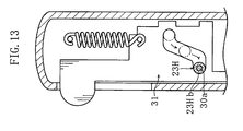
- Fig. 13 is a sectional view illustrating an impact absorbing means of an eighth embodiment of the present invention.
- Fig. 14 is a sectional view illustrating the impact absorbing means according to the present invention applied to another lancing device.
- Fig. 15 is a sectional view illustrating an example of a conventional lancing device.
- First through eighth preferred embodiments of the present invention are described below with reference to the accompanying drawings.
- A first embodiment of the present invention is described with reference to Figs. 1-8.
- As shown in Fig. 1, a lancing device X is used for puncturing skin to cause bleeding therefrom, by moving a
lancet 1 from a standby position (where thelancet 1 is illustrated by solid lines in the figure) to a puncturing position (where thelancet 1 is illustrated by phantom lines in the figure). The lancing device X includes ahousing 2, alancet moving mechanism 3, and a latch-releasingmember 4. - The above-described
lancet 1 for puncturing the skin is held in alancet holder 32 which will be described later, and moves integrally with thelancet holder 32. Thelancet 1 includes abody 10 and a lancingneedle 11 protruding from the body, and is disposable, for example. Thebody 10 is tubular and made of a resin, for example. The lancingneedle 11 is made of e.g. metal, and is integrated to thebody 10 by insert molding. The lancingneedle 11 of thelancet 1 may also adhere to thebody 10. - The
housing 2 defines a space for accommodating various components, and includes first andsecond sleeves - The
first sleeve 21 includes aprojection 21a and first andsecond openings projection 21a engages a movingplate 31 of thelancet moving mechanism 3. Thefirst opening 21b allows movement of an operatingportion 31B of the movingplate 31. Thesecond opening 21c allows movement of an end of the latch-releasingmember 4. - The
first sleeve 21 accommodates an impact absorbing means 23A in the vicinity of thefirst opening 21b. The impact absorbing means 23A is for contact with the operatingportion 31B of the movingplate 31, and includes a projection 23Aa formed in thefirst sleeve 21 and an elastic member 23Ab held by the projection. The elastic member 23Ab is a ring made of rubber or foam. - The
second sleeve 22 is a cylinder including open ends for allowing movement of thelancet holder 32, as described below. As shown in Figs. 1-2, thesecond sleeve 22 is attachable to and removable from a tip end of thefirst sleeve 21. Thus, thelancet 1 can be easily attached to thelancet holder 32 by removing thesecond sleeve 22 from thefirst sleeve 21. - As shown in Figs. 1-3, the
lancet moving mechanism 3 includes alink 30, a movingplate 31, and alancet holder 32. Thelancet moving mechanism 3 transforms reciprocal movement of the movingplate 31 into reciprocal movement of thelancet holder 32 via circular movement of thelink 30. - The
link 30 moves thelancet holder 32 in response to the movement of the movingplate 31. As shown in Figs. 3 and 4, thelink 30 includes a firstmovable pin 30a, a secondmovable pin 30b, a fixedpin 30c, afirst arm 30A, and asecond arm 30B. - As clearly shown in Fig. 3, the first
movable pin 30a engaging with the movingplate 31 connects thefirst arm 30A to thesecond arm 30B, and movable within agroove 31A of the movingplate 31. Themovable pin 30b engaging with thelancet holder 32 is movable within agroove 36 of thelancet holder 32. The fixedpin 30c rotatably attaches thelink 30 to the housing 2 (at the first sleeve 21). - As shown in Figs. 5A and 5B, the moving
plate 31 is movable relative to thehousing 2 in a puncturing direction N1 and in a retreating direction N2, and is connected to thehousing 2 via a coil spring Sp. The movingplate 31 includes agroove 31A, an operatingportion 31B, and ahook 31C. - The
groove 31A allows movement of the firstmovable pin 30a of the link 30 (see Figs. 3 and 4). Thegroove 31A includes an inclined portion 31Aa inclined relative to the puncturing and retreating directions N1, N2, and linear portions 31Ab connected to the ends of the inclined portion 31Aa. - The operating
portion 31B is used to manually move the movingplate 31. Theoperation portion 31B partially protrudes beyond thefirst opening 21b of thehousing 2, and moves within thefirst opening 21b in the puncturing and retreating directions N1, N2. - The
hook 31C engages with theprojection 21a of thehousing 2 for latching the movingplate 31 to thehousing 2. As clearly shown in Fig. 5B, when the coil spring Sp of the movingplate 31 is compressed, thehook 31C is in the retreating direction N2 with respect to theprojection 21a. On the other hand, as clearly shown in Fig. 5A, when thehook 31C of the movingplate 31 engages with theprojection 21a, the coil spring Sp is stretched with a restoring force applied in the retreating direction n2. - As shown in Figs. 1 and 2, the
lancet holder 32 holding thelancet 1 moves thelancet 1, and similarly to the movingplate 31, is movable in the puncturing and retreating direction N1, N2. As shown in Figs. 1 and 2, thelancet holder 32 includes aholder 35 for holding thelancet 1 and also includes agroove 36 connected with the movingplate 31 via thelink 30. - The
holder 35 includes arecess 35a having an inner form corresponding to the outer form of thelancet 1. As may be seen from Figs. 1-3, thegroove 36 allows movement of the secondmovable pin 30b of thelink 30 in a direction perpendicular to the puncturing and the retreating directions N1, N2. - As shown in Figs. 5A and 5B, the latch-releasing
member 4 for releasing the movingplate 31 from latching to thehousing 2 is suitably flexible and includes anend 41 fixed to the housing 2 (the first sleeve 21). Thus, theother end 42 of the latch-releasingmember 4 is pivotable about theend 41. Theend 42 is exposed at thesecond opening 21c of thehousing 2 and is movable within thesecond opening 21c. Thus, when theend 42 is pushed down, theend 42 moves inwardly of thehousing 2, thereby releasing the moving plate 31 (thehook 31C) from engagement with theprojection 21a of the housing 2 (the first sleeve 21). - Next, description is made as to the use and the operation of the lancing device X. Note that in the beginning, as shown in Fig. 6A, the moving
plate 31 retreats in the retreating direction N2 to the free position (upper dead point), and the firstmovable pin 30a is positioned at the left end of the inclined portion 31Aa of thegroove 31A of the movingplate 31, while the secondmovable pin 30b is positioned at the left end of thegroove 36 of thelancet holder 32. - As shown in Figs. 1 and 6C, on puncturing skin by the lancing device X, the
hook 31C of the movingplate 31 is brought into engagement with theprojection 21a of thehousing 2, and then thelancet 1 is attached to thelancet holder 32. However, the attachment of thelancet 1 to thelancet holder 32 may be performed before the latching of the movingplate 31 to thehousing 2. - As shown in Figs. 6A-6C, the
hook 31C is brought into engagement by moving the operatingportion 31B of the movingplate 31 in the puncturing direction N1. - On moving the moving
plate 31 in the puncturing direction N1 from the position shown in Fig. 6A,entire link 30 including the secondmovable pin 30b is rotated clockwise about the fixedpin 30c, and accordingly thelancet holder 32 retreats in the retreating direction N2, as shown in Figs. 6A and 6B. On moving the movingplate 31 in the puncturing direction N1 further from the position shown in Fig. 6B, thelink 30 is further rotated clockwise as shown in Fig. 6C, and accordingly thelancet holder 32 is advanced in the puncturing direction N1. In such an instance, the coil spring Sp is stretched and the movingplate 31 is latched to thehousing 2 with a restoring force applied in the retreating direction N2. - On attachment of the
lancet 1, thesecond sleeve 22 is removed from thefirst sleeve 21 as shown in Fig. 2, so that theholder 35 of thelancet holder 32 is exposed. In this state, thelancet 1 is inserted, at its portion opposite to the lancingneedle 11, into the holder 25. - After the completion of the latching of the moving
plate 31 as well as the attachment of thelancet 1, theend 42 of the latch-releasingmember 4 is pressed down, as shown in Figs. 5A and 5B, to puncture the skin. When theend 42 is pressed down, theend 42 pivots about theend 41, and theend 42 moves inwardly of thehousing 2. Then, theend 42 contacts thehook 31C to release thehook 31C from the engagement with theprojection 21a. - Here, the moving
plate 31 moves in the retreating direction N2 as the movingplate 31 is urged in the retreating direction N2 as described above, whereby thelink 30 rotates clockwise and thelancet holder 32 is advanced in the puncturing direction N1. Thereafter, the movingplate 31 is further moved in the retreating direction N2, whereby thelancet holder 32 retreats in the retreating direction N2. In this way, thelancet holder 32 comes back to the free position where the lancet holder is not latched to thehousing 2 as shown in Fig. 6A, whereby the lancingneedle 11 of thelancet 1 is removed from the skin. - The movement of the moving
plate 31 and thelancet holder 32 is stopped by the elastic member 23Ab of the impact absorbing means 23A that comes into contact with the operatingportion 31B of the movingplate 31. Specifically, the elastic member 23Ab absorbs the energy of the movement of the movingplate 31 to be stopped. Thus, the lancing device X can regulate the impact, the impact noise and the vibration on puncturing, thereby reducing the pain or discomfort of a user. - In the present embodiment, the impact absorbing means 23A is provided at a portion which comes into contact with the operating
portion 31B of the movingplate 31. However, the impact absorbing means 23A may be provided at other portion, as far as it comes into contact with any portion of the movingplate 31 when the movingplate 31 moves on puncture operation. - Next, second to eighth embodiments of the present invention are described below with reference to Figs. 7 to 13. In these figures, elements identical to those described in the first embodiment are given the same reference numbers.
- In the second embodiment, as shown in Figs. 7A and 7B, an impact absorbing means 23B is designed as a coil spring 23Bb. The coil spring 23Bb is provided at an
upper wall 24 of the housing 2 (first sleeve 21). - In this structure, the operating
portion 31B of the movingplate 31 is brought into contact with the coil spring 23Bb on puncture operation. Then, the coil spring 23Bb is elastically deformed to absorb the energy of the movement of the movingplate 31, thereby stopping the movement of the movingplate 31. - An impact absorbingmeans, similar to the impact absorbing means 23B may be provided by an elastic material other than the coil spring such as rubber or foam fixed to the upper wall of the housing, or may be provided by an elastic material such as the coil spring fixed to the moving
plate 31. - In a third embodiment, as shown in Figs. 8A and 8B, an impact absorbing means 23C is designed as an elastic member 23Cb provided at the upper end of the
first opening 21b of thehousing 2. The elastic member 23Cb may be made of various materials, such as rubber or foam. Of course, a spring such as a coil spring may be used as the elastic member. - In this structure, the operating
portion 31B of the movingplate 31 is brought into contact with the elastic member 23Cb on puncture operation. Then, the elastic member 23Cb is elastically deformed to absorb the energy of the movement of the movingplate 31, thereby stopping the movement of the movingplate 31. - In the present embodiment, the elastic member may be fixed to the moving
plate 31. - In a fourth embodiment, as shown in Figs. 9A and 9B, an impact absorbing means 23D utilizes the resistance for absorbing the energy of movement.
- The impact absorbing means 23D includes a lib 23Dc provided at an end of the moving
plate 31 and an interference wall 23Db provided on an inner surface of thehousing 2. The interference wall 23Db for contact with the lib 23Dc includes an inclined surface 23Db' inclined relative to the operatingportion 31B. - In this structure, as the moving
plate 31 moves in the N2 direction, the transfer resistance between the lib 23Dc and the interference surface 23Db' is increased, thereby gradually absorbing the energy of the movement of the movingplate 31. - The surface of the interference wall 23Db for contact with the lib 23Dc is not limited to the inclined surface, but may be a curved face. The lib may be provided at the
housing 2, while a member similar to the interference wall 23Db may be provided at the movingplate 31. - In a fifth embodiment, as shown in Figs. 10A and 10B, an impact absorbing means 23E is designed to absorb the energy of movement by the transfer resistance and the elastic deformation.
- The impact absorbing means 23E includes a plate spring 23Ec provided at the moving
plate 31 and an interference wall 23Eb provided on the inner surface of thehousing 2. The plate spring 23Ec is pivotable in a direction perpendicular to the moving direction of the moving plate 31 (N1, N2 directions) and includes a projection 23Ec' for contact with the interference wall 23Eb. On the other hand, the interference wall 23Eb includes an inclined surface 23Eb' inclined relative to the operatingportion 31B of the movingplate 31, for contact with the projection 23Ec'. - In the impact absorbing means 23E, as the moving
plate 31 moves in the N2 direction on puncturing, the transfer resistance between the projection 23Ec' and the inclined surface 23Eb' is increased, and the plate spring 23Ec is elastically deformed, thereby gradually absorbing the energy of the movement of the movingplate 31. - The plate spring may be provided at the housing, while the inclined surface for contact with the plate spring may be provided at the moving plate.
- In the first to fifth embodiments, the energy of movement is absorbed by the impact absorbing means 23A-23E that is brought into contact with the moving
plate 31. However, the energy of the movement may be absorbed by a similar impact absorbing means that is brought into contact with the lancet holder 32 (see Fig. 1). In this structure, such impact absorbing means for contact with the lancet holder may be replaced with the above impact absorbing means for contact with the moving plate, or may be used together with the impact absorbing means for contact with the moving plate. - In a sixth embodiment, as shown in Figs. 11A and 11B, an impact absorbing means 23F is provided at the
groove 31A of the movingplate 31. The impact absorbing means 23F includes an elastic member 23Fb positioned at the linear portion 31Ab of thegroove 31A. - In this structure, the first
movable pin 30a of the link 30 (see Fig. 1) is brought into contact with the elastic member 23Fb on puncturing, thereby stopping the movement of the movingplate 31. - In a seventh embodiment, as shown in Fig. 12, an impact absorbing means 23G is provided by utilizing the linear portion 31Ab of the moving
plate 31. Specifically, The impact absorbing means 23G is provided by forming the linear portion 31Ab to be narrower as proceeding to its end. - In this structure, the energy of the movement of the moving
plate 31 is gradually absorbed as the firstmovable pin 30a of the link 30 (see Fig. 1) moves in the linear portion 31Ab, thereby stopping the movingplate 31. - In an eighth embodiment, as shown in Fig. 13, an impact absorbing means 23H is provided at the first
movable pin 30a of the link 30 (see Fig. 1). The impact absorbing means 23H includes an elastic member 23Hb held at the firstmovable pin 30a. The elastic member 23Hb is a ring made of rubber or foam, for example. - In this structure, the elastic member 23Hb at the first
movable pin 30a of the link 30 (see Fig. 1) is brought into contact with the edge of thegroove 31A on puncturing, thereby stopping the movement of the movingplate 31. - In the sixth to eighth embodiments, the position of the first
movable pin 30a when stopping the movingplate 31 is variable. For example, the movingplate 31 may be stopped right after the firstmovable pin 30a turns round at the end of the linear portion 31Ab of thegroove 31A. In such a case, the movingplate 31 is slowed down when the firstmovable pin 30a is brought into contact with the impact absorbing means 23F, 23G, 23H, and then the movingplate 31 is stopped after the firstmovable pin 30a turns round. - The impact absorbing means 23F-23H of the sixth to eighth embodiments may be used together with the above-described impact absorbing means 23A-23E. An impact absorbing means similar to the impact absorbing means 23F-23H may be provided at the
groove 36 of the lancet holder 32 (see Fig. 1). In such a case, the impact absorbing means at thelancet holder 32 may be replaced with the impact absorbing means at the moving plate, or may be used together with the impact absorbing means at the moving plate. - Of course, the present invention is not limited to the impact absorbing means 23A-23H illustrated in the first to eighth embodiments, but a differently designed impact absorbing means may be provided. Further, the impact absorbing means may be applied to a lancing device other than the lancing device described in the first embodiment. For example, the impact absorbing means may be applied to a lancing
device 9 described as a conventional example with reference to Figs. 15A-15C. Specifically, as shown in Fig. 14A, an impact absorbing means 23I may be provided by positioning an elastic member 23Ib at theend 96a of thegroove 96 of thecam 90. As shown in Fig. 14B, an impact absorbing means 23J may be provided by forming theend 96a of thegroove 96 to be narrower as proceeding to its end. As shown in Fig. 14C, animpact absorbing means 2 3K may be provided by fitting an elastic member 23Kb around the ring-shaped engagingpin 97. Further, the lancingdevice 9 may be provided with various impact absorbing means which is brought into contact with the cam 90 (see Fig. 14A) to absorb the energy of movement, similarly to the impact absorbing means 23A-23E illustrated in the first to fifth embodiments, or may be provided with another impact absorbing means. - The present invention may further be applied to a lancing device in which a lancet holder is connected to a rotating member rotating around an axis elongated in the puncturing direction, and the lancet holder moves in response to the movement of the rotating member.
Claims (26)
- A lancing device comprising: a first moving member holding a lancing member moved from a standby position to a puncturing position in a puncturing direction, for puncturing a target portion by the lancing member; a second moving member connected to the first moving member, for controlling the movement of the first moving member upon the movement of the second moving member; a housing for accommodating the first and the second moving members, while allowing the movement of the moving members; and
an impact absorbing means for absorbing impact that is caused when the first and the second moving members come to stop on puncture operation. - The lancing device according to claim 1, wherein the impact absorbing means includes an elastic member for absorbing the impact by elastic deformation.
- The lancing device according to claim 2, wherein the elastic member is fixed to the housing.
- The lancing device according to claim 3, wherein the housing is provided with a projection for fixing the elastic member, the elastic member being a ring fitting around the projection.
- The lancing device according to claim 4, wherein the elastic member is made of rubber or foam.
- The lancing device according to claim 2, wherein the elastic member is a coil spring intervening between the housing and the first or the second moving member, when the first and the second moving members come to stop on puncture operation.
- The lancing device according to claim 2, wherein the second moving member comprises an operating portion including a portion protruding out of an opening of the housing,
the elastic member being provided at one of the opening and the operating portion. - The lancing device according to claim 2, wherein the elastic member is a plate spring provided at a portion at which the housing comes into contact with at least one of the first and the second moving members, when the first and the second moving members come to stop on puncture operation.
- The lancing device according to claim 2, further comprising a link connecting the first and the second moving members for moving the first moving members upon the movement of the second moving member,
wherein at least one of the first and the second moving members is formed with a groove for allowing movement of a shaft of the link. - The lancing device according to claim 9, wherein the elastic member is provided at an end of the groove.
- The lancing device according to claim 9, wherein the elastic member is provided at the shaft.
- The lancing device according to claim 1, wherein the impact absorbing means absorbs the energy of the movement of the first and the second moving members utilizing friction resistance.
- The lancing device according to claim 12, wherein the impact absorbing means includes an inclined or curved surface provided at a portion at which the housing comes into contact with at least one of the first and the second moving members, when the first and the second moving members come to stop on puncture operation.
- The lancing device according to claim 13, wherein the impact absorbing means includes a lib for contact with the inclined or curved surface, when the first and the second moving members come to stop on puncture operation.
- The lancing device according to claim 14, wherein the lib is provided at one or both of the first and the second moving members,
the inclined or curved surface being provided at the housing. - The lancing device according to claim 15, wherein the second moving member comprises an operating portion including a portion protruding out of an opening of the housing,
the lib being provided at the operating portion. - The lancing device according to claim 12, further comprising a link connecting the first and the second moving members for moving the first moving members upon the movement of the second moving member,
wherein at least one of the first and the second moving members is formed with a groove for allowing movement of a shaft of the link,
wherein the impact absorbingmeans is provided by tapering the end of the groove to form a portion narrower than the shaft in diameter, the shaft being brought into contact with the tapered portion to absorb the energy of the movement of the first and the second moving members. - The lancing device according to claim 1, wherein the impact absorbingmeans includes an elasticmember for absorbing impact by elastic deformation and also includes a frictional portion for absorbing the energy of the movement of the first and the second moving members utilizing friction resistance.
- The lancing device according to claim 18, wherein the frictional portion includes an inclined or curved surface provided at a portion at which the housing comes into contact with at least one of the first and the second moving members, when the first and the second moving members come to stop on puncture operation.
- The lancing device according to claim 19, wherein the elastic member is a plate spring for contact the inclined or curved surface, when the first and the second moving members come to stop on puncture operation.
- The lancing device according to claim 20, wherein the plate spring is movable in a direction across the puncturing direction.
- The lancing device according to claim 21, wherein the plate spring includes a projection protruding in a direction across the puncturing direction for contact with the inclined or curved surface.
- The lancing device according to claim 20, wherein the inclined or curved surface is provided at the housing,
the plate spring being provided at the second moving member. - The lancing device according to claim 1, wherein advance or reciprocal movement of the second moving member is transformed into reciprocal movement of the first moving member.
- The lancing device according to claim 24, wherein when the second moving member retreats in a direction opposite to the puncturing direction, the first moving member reciprocates in the puncturing direction and in the direction opposite to the puncturing direction.
- The lancing device according to claim 1, wherein rotation of the second moving member is transformed into advance or reciprocal movement of the first moving member.
Applications Claiming Priority (2)
| Application Number | Priority Date | Filing Date | Title |
|---|---|---|---|
| JP2003143194A JP4296035B2 (en) | 2003-05-21 | 2003-05-21 | Puncture device |
| PCT/JP2004/006846 WO2004103178A1 (en) | 2003-05-21 | 2004-05-20 | Needle insertion device |
Publications (3)
| Publication Number | Publication Date |
|---|---|
| EP1625825A1 true EP1625825A1 (en) | 2006-02-15 |
| EP1625825A4 EP1625825A4 (en) | 2010-02-17 |
| EP1625825B1 EP1625825B1 (en) | 2012-12-05 |
Family
ID=33475119
Family Applications (1)
| Application Number | Title | Priority Date | Filing Date |
|---|---|---|---|
| EP04734101A Active EP1625825B1 (en) | 2003-05-21 | 2004-05-20 | Needle insertion device |
Country Status (5)
| Country | Link |
|---|---|
| US (1) | US8506586B2 (en) |
| EP (1) | EP1625825B1 (en) |
| JP (1) | JP4296035B2 (en) |
| CN (1) | CN100457033C (en) |
| WO (1) | WO2004103178A1 (en) |
Cited By (4)
| Publication number | Priority date | Publication date | Assignee | Title |
|---|---|---|---|---|
| EP1852069A1 (en) * | 2006-05-04 | 2007-11-07 | Roche Diagnostics GmbH | System for sampling blood from a body part |
| EP1884191A1 (en) * | 2006-08-02 | 2008-02-06 | Roche Diagnostics GmbH | Lancet system |
| US8048098B2 (en) | 2005-07-14 | 2011-11-01 | Bayer Healthcare Llc | Lancing device for one skin puncture |
| CN110151194A (en) * | 2019-04-02 | 2019-08-23 | 天津华鸿科技股份有限公司 | Hemostix |
Families Citing this family (63)
| Publication number | Priority date | Publication date | Assignee | Title |
|---|---|---|---|---|
| US6391005B1 (en) | 1998-03-30 | 2002-05-21 | Agilent Technologies, Inc. | Apparatus and method for penetration with shaft having a sensor for sensing penetration depth |
| US8641644B2 (en) | 2000-11-21 | 2014-02-04 | Sanofi-Aventis Deutschland Gmbh | Blood testing apparatus having a rotatable cartridge with multiple lancing elements and testing means |
| US7981056B2 (en) | 2002-04-19 | 2011-07-19 | Pelikan Technologies, Inc. | Methods and apparatus for lancet actuation |
| US9226699B2 (en) | 2002-04-19 | 2016-01-05 | Sanofi-Aventis Deutschland Gmbh | Body fluid sampling module with a continuous compression tissue interface surface |
| DE60238119D1 (en) | 2001-06-12 | 2010-12-09 | Pelikan Technologies Inc | ELECTRIC ACTUATOR ELEMENT FOR A LANZETTE |
| US9427532B2 (en) | 2001-06-12 | 2016-08-30 | Sanofi-Aventis Deutschland Gmbh | Tissue penetration device |
| US8337419B2 (en) | 2002-04-19 | 2012-12-25 | Sanofi-Aventis Deutschland Gmbh | Tissue penetration device |
| US7316700B2 (en) | 2001-06-12 | 2008-01-08 | Pelikan Technologies, Inc. | Self optimizing lancing device with adaptation means to temporal variations in cutaneous properties |
| US9795747B2 (en) | 2010-06-02 | 2017-10-24 | Sanofi-Aventis Deutschland Gmbh | Methods and apparatus for lancet actuation |
| US7749174B2 (en) | 2001-06-12 | 2010-07-06 | Pelikan Technologies, Inc. | Method and apparatus for lancet launching device intergrated onto a blood-sampling cartridge |
| US7025774B2 (en) | 2001-06-12 | 2006-04-11 | Pelikan Technologies, Inc. | Tissue penetration device |
| US7901362B2 (en) | 2002-04-19 | 2011-03-08 | Pelikan Technologies, Inc. | Method and apparatus for penetrating tissue |
| US8267870B2 (en) | 2002-04-19 | 2012-09-18 | Sanofi-Aventis Deutschland Gmbh | Method and apparatus for body fluid sampling with hybrid actuation |
| US8579831B2 (en) | 2002-04-19 | 2013-11-12 | Sanofi-Aventis Deutschland Gmbh | Method and apparatus for penetrating tissue |
| US8360992B2 (en) | 2002-04-19 | 2013-01-29 | Sanofi-Aventis Deutschland Gmbh | Method and apparatus for penetrating tissue |
| US7713214B2 (en) | 2002-04-19 | 2010-05-11 | Pelikan Technologies, Inc. | Method and apparatus for a multi-use body fluid sampling device with optical analyte sensing |
| US9795334B2 (en) | 2002-04-19 | 2017-10-24 | Sanofi-Aventis Deutschland Gmbh | Method and apparatus for penetrating tissue |
| US9248267B2 (en) | 2002-04-19 | 2016-02-02 | Sanofi-Aventis Deustchland Gmbh | Tissue penetration device |
| US7976476B2 (en) | 2002-04-19 | 2011-07-12 | Pelikan Technologies, Inc. | Device and method for variable speed lancet |
| US8784335B2 (en) | 2002-04-19 | 2014-07-22 | Sanofi-Aventis Deutschland Gmbh | Body fluid sampling device with a capacitive sensor |
| US7909778B2 (en) | 2002-04-19 | 2011-03-22 | Pelikan Technologies, Inc. | Method and apparatus for penetrating tissue |
| US7491178B2 (en) | 2002-04-19 | 2009-02-17 | Pelikan Technologies, Inc. | Method and apparatus for penetrating tissue |
| US9314194B2 (en) | 2002-04-19 | 2016-04-19 | Sanofi-Aventis Deutschland Gmbh | Tissue penetration device |
| US7175642B2 (en) | 2002-04-19 | 2007-02-13 | Pelikan Technologies, Inc. | Methods and apparatus for lancet actuation |
| US7547287B2 (en) | 2002-04-19 | 2009-06-16 | Pelikan Technologies, Inc. | Method and apparatus for penetrating tissue |
| US7674232B2 (en) | 2002-04-19 | 2010-03-09 | Pelikan Technologies, Inc. | Method and apparatus for penetrating tissue |
| US7297122B2 (en) | 2002-04-19 | 2007-11-20 | Pelikan Technologies, Inc. | Method and apparatus for penetrating tissue |
| US8372016B2 (en) | 2002-04-19 | 2013-02-12 | Sanofi-Aventis Deutschland Gmbh | Method and apparatus for body fluid sampling and analyte sensing |
| US7331931B2 (en) | 2002-04-19 | 2008-02-19 | Pelikan Technologies, Inc. | Method and apparatus for penetrating tissue |
| US8221334B2 (en) | 2002-04-19 | 2012-07-17 | Sanofi-Aventis Deutschland Gmbh | Method and apparatus for penetrating tissue |
| US7892183B2 (en) | 2002-04-19 | 2011-02-22 | Pelikan Technologies, Inc. | Method and apparatus for body fluid sampling and analyte sensing |
| US7229458B2 (en) | 2002-04-19 | 2007-06-12 | Pelikan Technologies, Inc. | Method and apparatus for penetrating tissue |
| US8702624B2 (en) | 2006-09-29 | 2014-04-22 | Sanofi-Aventis Deutschland Gmbh | Analyte measurement device with a single shot actuator |
| US7232451B2 (en) | 2002-04-19 | 2007-06-19 | Pelikan Technologies, Inc. | Method and apparatus for penetrating tissue |
| US8574895B2 (en) | 2002-12-30 | 2013-11-05 | Sanofi-Aventis Deutschland Gmbh | Method and apparatus using optical techniques to measure analyte levels |
| US8262614B2 (en) | 2003-05-30 | 2012-09-11 | Pelikan Technologies, Inc. | Method and apparatus for fluid injection |
| US7850621B2 (en) | 2003-06-06 | 2010-12-14 | Pelikan Technologies, Inc. | Method and apparatus for body fluid sampling and analyte sensing |
| WO2006001797A1 (en) | 2004-06-14 | 2006-01-05 | Pelikan Technologies, Inc. | Low pain penetrating |
| WO2005033659A2 (en) | 2003-09-29 | 2005-04-14 | Pelikan Technologies, Inc. | Method and apparatus for an improved sample capture device |
| EP1680014A4 (en) | 2003-10-14 | 2009-01-21 | Pelikan Technologies Inc | Method and apparatus for a variable user interface |
| US8668656B2 (en) * | 2003-12-31 | 2014-03-11 | Sanofi-Aventis Deutschland Gmbh | Method and apparatus for improving fluidic flow and sample capture |
| US7822454B1 (en) | 2005-01-03 | 2010-10-26 | Pelikan Technologies, Inc. | Fluid sampling device with improved analyte detecting member configuration |
| WO2006011062A2 (en) | 2004-05-20 | 2006-02-02 | Albatros Technologies Gmbh & Co. Kg | Printable hydrogel for biosensors |
| US9775553B2 (en) | 2004-06-03 | 2017-10-03 | Sanofi-Aventis Deutschland Gmbh | Method and apparatus for a fluid sampling device |
| EP1765194A4 (en) | 2004-06-03 | 2010-09-29 | Pelikan Technologies Inc | Method and apparatus for a fluid sampling device |
| US8652831B2 (en) * | 2004-12-30 | 2014-02-18 | Sanofi-Aventis Deutschland Gmbh | Method and apparatus for analyte measurement test time |
| TW200640419A (en) | 2005-03-04 | 2006-12-01 | Bayer Healthcare Llc | Lancet-release mechanism |
| WO2006096539A1 (en) | 2005-03-04 | 2006-09-14 | Bayer Healthcare Llc | Lancet-release mechanism |
| EP2425775B1 (en) | 2005-04-07 | 2013-06-12 | Becton, Dickinson and Company | Lancet device |
| JP4536590B2 (en) * | 2005-05-16 | 2010-09-01 | パナソニック株式会社 | Puncture tool |
| AR057484A1 (en) | 2005-08-04 | 2007-12-05 | Bayer Healthcare Llc | SMALL PUNCTURE DEVICE |
| JPWO2007102576A1 (en) * | 2006-03-08 | 2009-07-23 | アークレイ株式会社 | Puncture device |
| JP5087749B2 (en) * | 2006-12-01 | 2012-12-05 | メディパーパス ピーティーイー リミテッド | Device for making an incision |
| US7963429B2 (en) * | 2007-08-21 | 2011-06-21 | William Carlton Zolentroff | Mid-zone stapler or pressing tool |
| EP2221000B1 (en) | 2007-11-27 | 2012-09-19 | ARKRAY, Inc. | Puncture device |
| EP2265324B1 (en) | 2008-04-11 | 2015-01-28 | Sanofi-Aventis Deutschland GmbH | Integrated analyte measurement system |
| US20090281457A1 (en) * | 2008-05-09 | 2009-11-12 | Lifescan Soctland Ltd. | Prime and fire lancing device with non-contacting bias drive and method |
| US8454533B2 (en) | 2008-05-09 | 2013-06-04 | Lifescan Scotland Limited | Lancing devices and methods |
| US8932314B2 (en) * | 2008-05-09 | 2015-01-13 | Lifescan Scotland Limited | Prime and fire lancing device with contacting bias drive and method |
| US9375169B2 (en) | 2009-01-30 | 2016-06-28 | Sanofi-Aventis Deutschland Gmbh | Cam drive for managing disposable penetrating member actions with a single motor and motor and control system |
| CN102481126B (en) | 2009-09-10 | 2014-08-06 | 旭石墨尼龙株式会社 | Lancet puncture device |
| US8965476B2 (en) | 2010-04-16 | 2015-02-24 | Sanofi-Aventis Deutschland Gmbh | Tissue penetration device |
| GB2498772A (en) | 2012-01-27 | 2013-07-31 | Owen Mumford Ltd | Lancing device moving lancet needle in longitudinal and lateral directions, lancet needle and lancing device with anti-recocking means |
Citations (6)
| Publication number | Priority date | Publication date | Assignee | Title |
|---|---|---|---|---|
| EP0569124A1 (en) * | 1992-05-05 | 1993-11-10 | Ryder International Corporation | Improved lancet actuator |
| WO1998006331A2 (en) * | 1996-08-13 | 1998-02-19 | Owen Mumford Limited | Improvements relating to skin prickers |
| US6045567A (en) * | 1999-02-23 | 2000-04-04 | Lifescan Inc. | Lancing device causing reduced pain |
| WO2001013794A1 (en) * | 1999-08-19 | 2001-03-01 | Owen Mumford Limited | Lancet |
| US6210421B1 (en) * | 1996-02-06 | 2001-04-03 | Roche Diagnostics Gmbh | Cutting device for skin for obtaining small blood samples in almost pain-free manner |
| EP1336375A2 (en) * | 2002-02-15 | 2003-08-20 | Roche Diagnostics GmbH | System for painless blood sampling |
Family Cites Families (15)
| Publication number | Priority date | Publication date | Assignee | Title |
|---|---|---|---|---|
| DE2642896C3 (en) * | 1976-09-24 | 1980-08-21 | 7800 Freiburg | Precision snapper for setting standard stab wounds in the skin for diagnostic purposes |
| US4328879A (en) * | 1978-04-27 | 1982-05-11 | The Gates Rubber Company | Shock-absorbing sprocket, drive assembly, and the like |
| JPS6442010A (en) | 1987-08-07 | 1989-02-14 | Matsushita Electric Ind Co Ltd | Magnetic head |
| JPS6442010U (en) * | 1987-09-07 | 1989-03-14 | ||
| CN2063020U (en) * | 1990-04-13 | 1990-10-03 | 李平荣 | Quick venipuncture apparatus without pain |
| US5545174A (en) * | 1994-01-11 | 1996-08-13 | Sherwood Medical Company | Finger stick device |
| PL332965A1 (en) * | 1996-10-28 | 1999-10-25 | Yissum Res Dev Co | Nucleic acid sequence encoding beta -c-4 oxygenase from haematococcus pluvialis for use in biosynthesis of astaxantin |
| US6231531B1 (en) * | 1999-04-09 | 2001-05-15 | Agilent Technologies, Inc. | Apparatus and method for minimizing pain perception |
| DE10121883A1 (en) * | 2001-05-05 | 2002-11-07 | Roche Diagnostics Gmbh | Blood Collection system |
| DE60238119D1 (en) * | 2001-06-12 | 2010-12-09 | Pelikan Technologies Inc | ELECTRIC ACTUATOR ELEMENT FOR A LANZETTE |
| JP2005511191A (en) * | 2001-06-13 | 2005-04-28 | シュラガ スティーブン | Single-use lancet device |
| DE10142232B4 (en) * | 2001-08-29 | 2021-04-29 | Roche Diabetes Care Gmbh | Process for the production of an analytical aid with a lancet and test element |
| US6929649B2 (en) * | 2002-04-23 | 2005-08-16 | Lifescan, Inc. | Lancing device with automatic stick and return |
| DE10223558A1 (en) * | 2002-05-28 | 2003-12-11 | Roche Diagnostics Gmbh | System useful in withdrawing blood for diagnostic purposes, has housing, lancet guide and lancet drive provided with drive spring, cocking device, drive rotor and outputs side coupling mechanism |
| CA2444630A1 (en) * | 2002-10-15 | 2004-04-15 | Bayer Healthcare Llc | Lancing device |
-
2003
- 2003-05-21 JP JP2003143194A patent/JP4296035B2/en not_active Expired - Fee Related
-
2004
- 2004-05-20 CN CNB2004800138923A patent/CN100457033C/en active Active
- 2004-05-20 EP EP04734101A patent/EP1625825B1/en active Active
- 2004-05-20 US US10/557,515 patent/US8506586B2/en active Active
- 2004-05-20 WO PCT/JP2004/006846 patent/WO2004103178A1/en active Application Filing
Patent Citations (6)
| Publication number | Priority date | Publication date | Assignee | Title |
|---|---|---|---|---|
| EP0569124A1 (en) * | 1992-05-05 | 1993-11-10 | Ryder International Corporation | Improved lancet actuator |
| US6210421B1 (en) * | 1996-02-06 | 2001-04-03 | Roche Diagnostics Gmbh | Cutting device for skin for obtaining small blood samples in almost pain-free manner |
| WO1998006331A2 (en) * | 1996-08-13 | 1998-02-19 | Owen Mumford Limited | Improvements relating to skin prickers |
| US6045567A (en) * | 1999-02-23 | 2000-04-04 | Lifescan Inc. | Lancing device causing reduced pain |
| WO2001013794A1 (en) * | 1999-08-19 | 2001-03-01 | Owen Mumford Limited | Lancet |
| EP1336375A2 (en) * | 2002-02-15 | 2003-08-20 | Roche Diagnostics GmbH | System for painless blood sampling |
Non-Patent Citations (1)
| Title |
|---|
| See also references of WO2004103178A1 * |
Cited By (7)
| Publication number | Priority date | Publication date | Assignee | Title |
|---|---|---|---|---|
| US8048098B2 (en) | 2005-07-14 | 2011-11-01 | Bayer Healthcare Llc | Lancing device for one skin puncture |
| US8333782B2 (en) | 2005-07-14 | 2012-12-18 | Bayer Healthcare Llc | Lancing device for one skin puncture |
| EP1852069A1 (en) * | 2006-05-04 | 2007-11-07 | Roche Diagnostics GmbH | System for sampling blood from a body part |
| US8932313B2 (en) | 2006-05-04 | 2015-01-13 | Roche Diagnostics Operations, Inc. | Blood collection system for collecting blood from a body part for diagnostic purposes |
| EP1884191A1 (en) * | 2006-08-02 | 2008-02-06 | Roche Diagnostics GmbH | Lancet system |
| CN110151194A (en) * | 2019-04-02 | 2019-08-23 | 天津华鸿科技股份有限公司 | Hemostix |
| CN110151194B (en) * | 2019-04-02 | 2022-04-05 | 天津华鸿科技股份有限公司 | Blood sampler |
Also Published As
| Publication number | Publication date |
|---|---|
| JP4296035B2 (en) | 2009-07-15 |
| EP1625825A4 (en) | 2010-02-17 |
| WO2004103178A1 (en) | 2004-12-02 |
| CN1791357A (en) | 2006-06-21 |
| CN100457033C (en) | 2009-02-04 |
| US8506586B2 (en) | 2013-08-13 |
| EP1625825B1 (en) | 2012-12-05 |
| US20070055297A1 (en) | 2007-03-08 |
| JP2004344292A (en) | 2004-12-09 |
Similar Documents
| Publication | Publication Date | Title |
|---|---|---|
| EP1625825A1 (en) | Needle insertion device | |
| US8372104B2 (en) | Lancet for blood collection and puncture needle unit | |
| JP4621853B2 (en) | Puncture device | |
| WO2003005906A1 (en) | Piercing device | |
| JP5640084B2 (en) | Lance retractable lancet | |
| JP4761701B2 (en) | Puncture device with adjustable puncture depth | |
| KR100570387B1 (en) | skin pricker | |
| EP1810616B1 (en) | Lancing device with dampener | |
| JP4901723B2 (en) | Diaphragm medical puncture device | |
| US20070010841A1 (en) | Lancet assembly | |
| EP2298161A1 (en) | Puncture device and puncture needle cartridge | |
| US8308747B2 (en) | Puncture device | |
| JP2005518858A (en) | Device for puncturing a patient's skin | |
| JP2011519647A (en) | Pre-launch preparation and launch of a lancing device with a contact energizing drive and method | |
| CA2990649C (en) | Contact activated lancet device | |
| JP4507600B2 (en) | Blood sampling puncture device and puncture needle unit | |
| EP1080688B1 (en) | Lancet | |
| JP6429770B2 (en) | One-way drive mechanism for puncture device | |
| JP4484669B2 (en) | Puncture device | |
| JP4762341B2 (en) | Puncture device | |
| RU2455933C2 (en) | Puncturing device for blood sampling for medical tests | |
| JP2005176924A (en) | Puncturing utensil for blood sampling | |
| JP3902989B2 (en) | Puncture device |
Legal Events
| Date | Code | Title | Description |
|---|---|---|---|
| PUAI | Public reference made under article 153(3) epc to a published international application that has entered the european phase |
Free format text: ORIGINAL CODE: 0009012 |
|
| 17P | Request for examination filed |
Effective date: 20051124 |
|
| AK | Designated contracting states |
Kind code of ref document: A1 Designated state(s): AT BE BG CH CY CZ DE DK EE ES FI FR GB GR HU IE IT LI LU MC NL PL PT RO SE SI SK TR |
|
| DAX | Request for extension of the european patent (deleted) | ||
| A4 | Supplementary search report drawn up and despatched |
Effective date: 20100120 |
|
| 17Q | First examination report despatched |
Effective date: 20100324 |
|
| GRAP | Despatch of communication of intention to grant a patent |
Free format text: ORIGINAL CODE: EPIDOSNIGR1 |
|
| GRAS | Grant fee paid |
Free format text: ORIGINAL CODE: EPIDOSNIGR3 |
|
| GRAA | (expected) grant |
Free format text: ORIGINAL CODE: 0009210 |
|
| AK | Designated contracting states |
Kind code of ref document: B1 Designated state(s): AT BE BG CH CY CZ DE DK EE ES FI FR GB GR HU IE IT LI LU MC NL PL PT RO SE SI SK TR |
|
| REG | Reference to a national code |
Ref country code: GB Ref legal event code: FG4D |
|
| REG | Reference to a national code |
Ref country code: CH Ref legal event code: EP |
|
| REG | Reference to a national code |
Ref country code: AT Ref legal event code: REF Ref document number: 586826 Country of ref document: AT Kind code of ref document: T Effective date: 20121215 |
|
| REG | Reference to a national code |
Ref country code: IE Ref legal event code: FG4D |
|
| REG | Reference to a national code |
Ref country code: DE Ref legal event code: R096 Ref document number: 602004040296 Country of ref document: DE Effective date: 20130131 |
|
| REG | Reference to a national code |
Ref country code: AT Ref legal event code: MK05 Ref document number: 586826 Country of ref document: AT Kind code of ref document: T Effective date: 20121205 |
|
| PG25 | Lapsed in a contracting state [announced via postgrant information from national office to epo] |
Ref country code: ES Free format text: LAPSE BECAUSE OF FAILURE TO SUBMIT A TRANSLATION OF THE DESCRIPTION OR TO PAY THE FEE WITHIN THE PRESCRIBED TIME-LIMIT Effective date: 20130316 Ref country code: FI Free format text: LAPSE BECAUSE OF FAILURE TO SUBMIT A TRANSLATION OF THE DESCRIPTION OR TO PAY THE FEE WITHIN THE PRESCRIBED TIME-LIMIT Effective date: 20121205 Ref country code: SE Free format text: LAPSE BECAUSE OF FAILURE TO SUBMIT A TRANSLATION OF THE DESCRIPTION OR TO PAY THE FEE WITHIN THE PRESCRIBED TIME-LIMIT Effective date: 20121205 |
|
| REG | Reference to a national code |
Ref country code: NL Ref legal event code: VDEP Effective date: 20121205 |
|
| PG25 | Lapsed in a contracting state [announced via postgrant information from national office to epo] |
Ref country code: PL Free format text: LAPSE BECAUSE OF FAILURE TO SUBMIT A TRANSLATION OF THE DESCRIPTION OR TO PAY THE FEE WITHIN THE PRESCRIBED TIME-LIMIT Effective date: 20121205 Ref country code: GR Free format text: LAPSE BECAUSE OF FAILURE TO SUBMIT A TRANSLATION OF THE DESCRIPTION OR TO PAY THE FEE WITHIN THE PRESCRIBED TIME-LIMIT Effective date: 20130306 Ref country code: CY Free format text: LAPSE BECAUSE OF FAILURE TO SUBMIT A TRANSLATION OF THE DESCRIPTION OR TO PAY THE FEE WITHIN THE PRESCRIBED TIME-LIMIT Effective date: 20121205 Ref country code: SI Free format text: LAPSE BECAUSE OF FAILURE TO SUBMIT A TRANSLATION OF THE DESCRIPTION OR TO PAY THE FEE WITHIN THE PRESCRIBED TIME-LIMIT Effective date: 20121205 |
|
| PG25 | Lapsed in a contracting state [announced via postgrant information from national office to epo] |
Ref country code: AT Free format text: LAPSE BECAUSE OF FAILURE TO SUBMIT A TRANSLATION OF THE DESCRIPTION OR TO PAY THE FEE WITHIN THE PRESCRIBED TIME-LIMIT Effective date: 20121205 |
|
| PG25 | Lapsed in a contracting state [announced via postgrant information from national office to epo] |
Ref country code: BG Free format text: LAPSE BECAUSE OF FAILURE TO SUBMIT A TRANSLATION OF THE DESCRIPTION OR TO PAY THE FEE WITHIN THE PRESCRIBED TIME-LIMIT Effective date: 20130305 Ref country code: EE Free format text: LAPSE BECAUSE OF FAILURE TO SUBMIT A TRANSLATION OF THE DESCRIPTION OR TO PAY THE FEE WITHIN THE PRESCRIBED TIME-LIMIT Effective date: 20121205 Ref country code: BE Free format text: LAPSE BECAUSE OF FAILURE TO SUBMIT A TRANSLATION OF THE DESCRIPTION OR TO PAY THE FEE WITHIN THE PRESCRIBED TIME-LIMIT Effective date: 20121205 Ref country code: SK Free format text: LAPSE BECAUSE OF FAILURE TO SUBMIT A TRANSLATION OF THE DESCRIPTION OR TO PAY THE FEE WITHIN THE PRESCRIBED TIME-LIMIT Effective date: 20121205 Ref country code: CZ Free format text: LAPSE BECAUSE OF FAILURE TO SUBMIT A TRANSLATION OF THE DESCRIPTION OR TO PAY THE FEE WITHIN THE PRESCRIBED TIME-LIMIT Effective date: 20121205 |
|
| PG25 | Lapsed in a contracting state [announced via postgrant information from national office to epo] |
Ref country code: PT Free format text: LAPSE BECAUSE OF FAILURE TO SUBMIT A TRANSLATION OF THE DESCRIPTION OR TO PAY THE FEE WITHIN THE PRESCRIBED TIME-LIMIT Effective date: 20130405 Ref country code: RO Free format text: LAPSE BECAUSE OF FAILURE TO SUBMIT A TRANSLATION OF THE DESCRIPTION OR TO PAY THE FEE WITHIN THE PRESCRIBED TIME-LIMIT Effective date: 20121205 Ref country code: NL Free format text: LAPSE BECAUSE OF FAILURE TO SUBMIT A TRANSLATION OF THE DESCRIPTION OR TO PAY THE FEE WITHIN THE PRESCRIBED TIME-LIMIT Effective date: 20121205 |
|
| PLBE | No opposition filed within time limit |
Free format text: ORIGINAL CODE: 0009261 |
|
| STAA | Information on the status of an ep patent application or granted ep patent |
Free format text: STATUS: NO OPPOSITION FILED WITHIN TIME LIMIT |
|
| PG25 | Lapsed in a contracting state [announced via postgrant information from national office to epo] |
Ref country code: DK Free format text: LAPSE BECAUSE OF FAILURE TO SUBMIT A TRANSLATION OF THE DESCRIPTION OR TO PAY THE FEE WITHIN THE PRESCRIBED TIME-LIMIT Effective date: 20121205 |
|
| 26N | No opposition filed |
Effective date: 20130906 |
|
| PG25 | Lapsed in a contracting state [announced via postgrant information from national office to epo] |
Ref country code: MC Free format text: LAPSE BECAUSE OF FAILURE TO SUBMIT A TRANSLATION OF THE DESCRIPTION OR TO PAY THE FEE WITHIN THE PRESCRIBED TIME-LIMIT Effective date: 20121205 |
|
| REG | Reference to a national code |
Ref country code: CH Ref legal event code: PL |
|
| REG | Reference to a national code |
Ref country code: DE Ref legal event code: R097 Ref document number: 602004040296 Country of ref document: DE Effective date: 20130906 |
|
| PG25 | Lapsed in a contracting state [announced via postgrant information from national office to epo] |
Ref country code: LI Free format text: LAPSE BECAUSE OF NON-PAYMENT OF DUE FEES Effective date: 20130531 Ref country code: CH Free format text: LAPSE BECAUSE OF NON-PAYMENT OF DUE FEES Effective date: 20130531 |
|
| REG | Reference to a national code |
Ref country code: IE Ref legal event code: MM4A |
|
| PG25 | Lapsed in a contracting state [announced via postgrant information from national office to epo] |
Ref country code: IE Free format text: LAPSE BECAUSE OF NON-PAYMENT OF DUE FEES Effective date: 20130520 |
|
| REG | Reference to a national code |
Ref country code: FR Ref legal event code: PLFP Year of fee payment: 12 |
|
| PG25 | Lapsed in a contracting state [announced via postgrant information from national office to epo] |
Ref country code: TR Free format text: LAPSE BECAUSE OF FAILURE TO SUBMIT A TRANSLATION OF THE DESCRIPTION OR TO PAY THE FEE WITHIN THE PRESCRIBED TIME-LIMIT Effective date: 20121205 |
|
| PG25 | Lapsed in a contracting state [announced via postgrant information from national office to epo] |
Ref country code: HU Free format text: LAPSE BECAUSE OF FAILURE TO SUBMIT A TRANSLATION OF THE DESCRIPTION OR TO PAY THE FEE WITHIN THE PRESCRIBED TIME-LIMIT; INVALID AB INITIO Effective date: 20040520 Ref country code: LU Free format text: LAPSE BECAUSE OF NON-PAYMENT OF DUE FEES Effective date: 20130520 |
|
| REG | Reference to a national code |
Ref country code: FR Ref legal event code: PLFP Year of fee payment: 13 |
|
| REG | Reference to a national code |
Ref country code: FR Ref legal event code: PLFP Year of fee payment: 14 |
|
| REG | Reference to a national code |
Ref country code: FR Ref legal event code: PLFP Year of fee payment: 15 |
|
| PGFP | Annual fee paid to national office [announced via postgrant information from national office to epo] |
Ref country code: IT Payment date: 20230526 Year of fee payment: 20 Ref country code: FR Payment date: 20230525 Year of fee payment: 20 Ref country code: DE Payment date: 20230519 Year of fee payment: 20 |
|
| PGFP | Annual fee paid to national office [announced via postgrant information from national office to epo] |
Ref country code: GB Payment date: 20230523 Year of fee payment: 20 |