EP1623670A1 - Capsule-type endoscope - Google Patents
Capsule-type endoscope Download PDFInfo
- Publication number
- EP1623670A1 EP1623670A1 EP05015570A EP05015570A EP1623670A1 EP 1623670 A1 EP1623670 A1 EP 1623670A1 EP 05015570 A EP05015570 A EP 05015570A EP 05015570 A EP05015570 A EP 05015570A EP 1623670 A1 EP1623670 A1 EP 1623670A1
- Authority
- EP
- European Patent Office
- Prior art keywords
- capsule
- optical system
- objective optical
- type endoscope
- transparent cover
- Prior art date
- Legal status (The legal status is an assumption and is not a legal conclusion. Google has not performed a legal analysis and makes no representation as to the accuracy of the status listed.)
- Granted
Links
Images


Classifications
-
- A—HUMAN NECESSITIES
- A61—MEDICAL OR VETERINARY SCIENCE; HYGIENE
- A61B—DIAGNOSIS; SURGERY; IDENTIFICATION
- A61B1/00—Instruments for performing medical examinations of the interior of cavities or tubes of the body by visual or photographical inspection, e.g. endoscopes; Illuminating arrangements therefor
- A61B1/04—Instruments for performing medical examinations of the interior of cavities or tubes of the body by visual or photographical inspection, e.g. endoscopes; Illuminating arrangements therefor combined with photographic or television appliances
- A61B1/041—Capsule endoscopes for imaging
-
- A—HUMAN NECESSITIES
- A61—MEDICAL OR VETERINARY SCIENCE; HYGIENE
- A61B—DIAGNOSIS; SURGERY; IDENTIFICATION
- A61B1/00—Instruments for performing medical examinations of the interior of cavities or tubes of the body by visual or photographical inspection, e.g. endoscopes; Illuminating arrangements therefor
- A61B1/00064—Constructional details of the endoscope body
- A61B1/00071—Insertion part of the endoscope body
- A61B1/0008—Insertion part of the endoscope body characterised by distal tip features
- A61B1/00096—Optical elements
-
- A—HUMAN NECESSITIES
- A61—MEDICAL OR VETERINARY SCIENCE; HYGIENE
- A61B—DIAGNOSIS; SURGERY; IDENTIFICATION
- A61B5/00—Measuring for diagnostic purposes; Identification of persons
- A61B5/07—Endoradiosondes
- A61B5/073—Intestinal transmitters
Definitions
- capsule-type endoscopes contain, for example, an objective optical system, an illumination means, an image pickup element, and a transmission means within a capsule-shaped shell.
- a cover member (hereinafter termed a transparent cover) that is generally spherical in shape and transparent within the field of view of the objective optical system seals these items within the capsule-shaped shell.
- a capsule-type endoscope having the above-discussed structure converts into signals in vivo images that are captured on a light- receiving surface of the image pickup element. These signals, of images that have been captured using light that has passed through the transparent cover and the objective optical system, are then transmitted externally by means of the transmission means. The transmitted signals are received by an external receiver device, and are then displayed on a display device for examination.
- Capsule-type endoscopes as discussed above have a problem in that illumination light emitted from the illumination means is partly reflected by the inner surface of the spherical transparent cover and enters the entrance pupil of the objective optical system, which causes flare and significantly deteriorates the image contrast.
- Japanese Laid-Open Patent Application 2003-325441 discloses a capsule-type endoscope in which the transparent cover has a spherical inner surface and the center of the entrance pupil of the objective optical system coincides with the center of curvature of this surface. Light that is emitted from the illumination means and reflected by the inner surface of the transparent cover is prevented from reaching the entrance pupil of the objective optical system, thus preventing flare.
- Japanese Laid-Open Patent Publication 2003-501704 discloses an optical device in which the transparent cover has an ellipsoidal inner surface and multiple light sources that function as an illumination means are provided along a focal curve on the focal plane of the ellipsoid. Once again, the light that is emitted from the illumination means and reflected by the inner surface of the transparent cover is prevented from reaching the objective optical system and causing flare.
- the capsule-type endoscope disclosed in Japanese Laid-Open Patent Application 2003-325441 requires that the illumination means be positioned around the objective optical system because of the structure that the center of the entrance pupil of the objective optical system coincides with the center of curvature of the inner surface of the transparent cover. This disadvantageously increases the size of the capsule-type endoscope.
- the light emitting elements that are used as the illumination means of the optical device disclosed in Japanese Laid-Open Patent Publication 2003-501704 must be located on the focal curve. Consequently, in order to provide sufficient room in which to mount these light- emitting elements, the transparent cover has to be increased in size, which requires that the size of the capsule-type endoscope itself be larger.
- the capsule-type endoscope described above provide a space for carrying a battery for ensuring sufficient operation time of the capsule-type endoscope or a tank for carrying a substance in liquid form.
- the location of such a space must be such that no interference occurs between the objective optical system and the illumination means. This requirement tends to increase the size of the capsule-type endoscope.
- the present invention relates to a capsule-type endoscope that can be swallowed for an in vivo examination.
- the purpose of the present invention is to provide a capsule-type endoscope that can prevent light that is reflected by the inner surface of the transparent cover from causing flare in the objective optical system, even if the size of the capsule-type endoscope is decreased.
- Another purpose of the present invention is to provide a capsule-type endoscope that can prevent light that is reflected by the inner surface of the transparent cover from causing flare in the objective optical system while simultaneously providing a sufficient space for mounting either a tank for carrying a substance in liquid form (such as a coloring agent or drug) for applying to a target region of a patient or a battery for increasing the operating time of the capsule-type endoscope.
- a substance in liquid form such as a coloring agent or drug
- a capsule-type endoscope is provided with an image pickup unit that includes an objective optical system, an image pickup element, and an illumination light source.
- An image pickup unit that includes an objective optical system, an image pickup element, and an illumination light source.
- a transparent cover that is transparent within the field of view of the objective optical system, seals these components within an external surface.
- the inner surface of the transparent cover is spherical so as to have a center of curvature, the optical axis of the objective optical system is offset from the center of curvature of the transparent cover, and the following Condition (1) is satisfied: 0.01 ⁇ L 1 / R tan ⁇ ⁇ 0.5 where L1 is the distance between the center of curvature of the inner surface of the transparent cover and the optical axis of the objective optical system; R is the radius of curvature of the inner surface of the transparent cover; and ⁇ is the half-field angle of the objective optical system.
- the light emitting surface(s) of the light sources that form an illumination means are positioned in a manner such that the light emitting surface(s) does (do) not overlap an image of the entrance pupil of the objective optical system when light rays are projected onto a plane Qm by being reflected by the inner surface of the transparent cover, where the plane Qm is defined as the plane containing the light emitting surface(s) of the illumination means.
- the present invention provides a capsule-type endoscope that can prevent light that is reflected by the inner surface of the transparent cover from causing flare in the objective optical system, even in the case where the capsule size is reduced or while ensuring that there exists a space for mounting either a tank for carrying a substance in liquid form or a battery for increasing the operating time of the capsule-type endoscope.
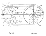
- the present invention will first be discussed in general terms with reference to Figs. 1(a) and 1(b).
- Figs. 1(a) and 1(b) are sectional illustrations of a capsule-type endoscope according to one embodiment of the present invention as viewed from the side and front, respectively.
- item 4 is the optical axis of the objective optical system 3
- St is the vertex of the inner surface 10 of the transparent cover 8.
- the vertex St is a point on the inner surface 10 of the transparent cover 8 at which the distance between two points Gn and En is largest.
- Gn is a point on the inner surface 10 of the transparent cover 8 and En is the intersection of a normal from the point Gn to a plane that is orthogonal to the optical axis and tangential to the most object side surface (surface being nearest to an object) of the objective optical system 3.
- Item 9 is the outer surface of the transparent cover
- P(Pc) is the center of the entrance pupil of the objective optical system 3
- P'c is the point of intersection of hypothetical light rays if emitted from the center Pc of the entrance pupil and reflected by the inner surface 10 of the transparent cover 8.
- Qm is as defined above, namely, the plane containing the light emitting surface(s) of the illumination means
- X is the point of intersection of a line drawn from the vertex St of the inner surface of the transparent cover normal to the plane Qm
- Region 15 (herein termed the reflected image of the entrance pupil of the objective optical system) is defined by the outer limit of hypothetical light rays emitted from the center of the entrance pupil of the objective optical system 3, when such hypothetical light rays are then reflected by the inner surface 10 of the transparent cover 8 so as to be incident onto the plane Qm.
- the capsule-type endoscope shown in Figs. 1(a) and 1(b) is an embodiment of the present invention in which the inner surface 10 of the transparent cover 8 is spherical.
- the objective optical system 3 is provided with the center Pc of its entrance pupil on a line 17 (in the plane Qm) that passes through the center of curvature 11 of the inner surface 10 of the transparent cover 8 and is orthogonal to the optical axis 4 of the objective optical system 3.
- the dashed lines 7', 7' define the outer limits of the field of view of a prior art capsule-type endoscope in which the center Pc of the entrance pupil of the objective optical system 3 coincides with the center of curvature 11 of the inner surface 10 of the transparent cover 8.
- the solid lines 7, 7 define the outer limits of the field of view of the objective optical system 3 when the center Pc of the entrance pupil of the objective optical system 3 is provided at a point that is laterally offset from the center of curvature 11, and when the above Condition (1) is satisfied.
- the outer surface 9 of the transparent cover 8 has its center of curvature at 12.
- the light emitting surface(s) of the illumination means 13 does (do) not overlap the reflected image 15 of the entrance pupil of the objective optical system 3 on the plane Qm, as can be seen in the capsule-type endoscope shown in Figs. 1(a) and 1(b).
- illumination light emitted from the illumination means 13 and reflected by the inner surface of the transparent cover 8 does not reach the entrance pupil of the objective optical system 3, thereby preventing flare.
- the objective optical system 3 When the upper limit of Condition (1) above is not satisfied, the objective optical system 3 is too close to the vertex St of the inner surface 10 of the transparent cover 8, failing to reserve a space for providing the illumination light source. On the other hand, when the lower limit of Condition (1) is not satisfied, the objective optical system 3 is too far away from the vertex St of the inner surface 10 of the transparent cover 8, unfavorably increasing the entire capsule length.
- the objective optical system be provided in a manner such that its optical axis is non-orthogonal to the inner surface of the transparent cover, and at least one of the components of the image pickup unit tilted so as to be non-orthogonal to the optical axis of the objective optical system or is de-centered relative to other components of the image pickup unit.
- Fig. 2 is an illustration to explain another important feature of the capsule-type endoscope of the present invention. It shows object points on the outer surface 9 of the transparent cover 8 at the outer limits of the field of view of the objective optical system 3 (in a cross section that contains the optical axis 4 of the objective optical system 3 and the vertex St of the inner surface 10 of the transparent cover 8) being imaged by the objective optical system 3.
- the capsule-type endoscope of the present invention does not have a mechanism for sending air into the organ during observation/diagnosis. Therefore, the digestive tract (i.e., the usual passageway of the capsule endoscope) is presumably contracted and thus at least partially blocks the field of view of the objective optical system of the capsule-type endoscope.
- the inner wall of the tubular organ is in contact with the outer surface of the capsule in the most stable manner and the inner wall of the tubular organ also surrounds the outer surface of the transparent cover along its curved surface. Therefore, it is desired that the image pickup unit be able to focus on an object point that is located on the outer surface 9 of the transparent cover 8.
- the image pickup unit 1 may be formed of an objective optical system 3 having lens components 5, 5 (which, as shown, may each consist of a lens element), a diaphragm (not shown), a lens frame (not shown), a spacing ring (not shown), an image pickup element 2, and an image pickup element frame (not shown).
- lens components 5, 5 which, as shown, may each consist of a lens element
- diaphragm not shown
- lens frame not shown
- spacing ring not shown
- an image pickup element 2 an image pickup element frame
- the objective optical system 3 when the objective optical system 3 is positioned with the center of its entrance pupil shifted from the center line of the capsule so that the optical axis of the objective optical system 3 is non-orthogonal to the inner surface of the transparent cover 8, the distance between the most object-side surface of the objective optical system 3 and the outer surface 9 of the transparent cover 8 varies, depending on the direction of viewing. This results in a shifting of the image position for each object point.
- an object of interest such as the inner surface of a tubular organ that is in contact with the outer surface of the transparent cover 8 will have a portion that is not properly focused onto the surface of the image pickup element, and this will cause difficulty in observation.
- the image pickup element 2 is tilted so as to be non-orthogonal to the optical axis of the objective optical system 3 in such a manner that the image pickup surface is positioned at the image positions XN1', XN2' that correspond to the distances XN1, XN2 between the most object-side surface of the objective optical system 3 and the outer surface 9 of the transparent cover 8.
- focal shifts as a result of differences in the object point distance to the outer surface 9 of the transparent cover 8 in different viewing directions is corrected.
- a small-sized, capsule-type endoscope that allows for clear observations of an object, such as the inner wall of a tubular organ, that is in contact with the outer surface 9 of the transparent cover 8 can be provided.
- At least one of the components of the image pickup unit other than the image pickup element can be de-centered relative to other components of the image pickup unit. In this way, focal shifts as a result of differences in the object distance to the outer surface 9 of the transparent cover 8 in different viewing directions can be similarly corrected and clear images can be obtained.
- Figs. 3(a) and 3(b) are illustrations which show the front portion of a capsule-type endoscope according to Embodiment 1 of the present invention, with Fig. 3(a) being a cross-section of a front portion of the capsule-type endoscope as viewed from the side, and Fig. 3(b) being a cross-section of a front portion of the capsule-type endoscope as viewed from the front.
- Like items in the drawings have been similarly numbered throughout the drawings.
- the illumination means 13 may be formed of semiconductor-chip-type, light emitting diodes (hereinafter termed LEDs), that are provided at different positions within the capsule, and the capsule-type endoscope is provided with a cover that is transparent within the field of view of the objective optical system 3 and that seals the capsule.
- the entrance pupil of the objective optical system 3 coincides with the most object-side surface of the lens components 5, 5 that form the objective optical system 3. Furthermore, the entrance pupil plane is on the same plane as the plane Qm that contains the light emitting surface(s) of the illumination means 13.
- a power supply battery and a transmission antenna for transmitting information, such as images, to a separate receiver device (not shown) are provided behind (i.e., on the image side of) the objective optical system 3.
- the inner surface 10 of the transparent cover 8 is spherical, and the center of curvature 11 of the inner surface 10 of the transparent cover 8 is on a line 17 that passes through the center Pc of the entrance pupil of the objective optical system 3 and is orthogonal to the optical axis 4 of the objective optical system 3.
- the lines 7, 7 are drawn through the center of the entrance pupil of the objective optical system 3 so as to pass through the points Sm and Sn that are located on the inner surface 10 of the transparent cover and these lines define the outer limits of the field of view of the objective optical system 3.
- the size of the capsule can be reduced relative to that of prior art capsule-type endoscopes by offsetting the optical axis of the objective optical system from the axial center of the capsule.
- the offset amount is 0.76 mm for a prior art transparent cover having an outer diameter of 5.6 mm.
- the reflected image range 15 of the entrance pupil of the objective optical system is defined herein as the intersection points with the plane Qm of hypothetical light rays that emerge from the center Pc of the entrance pupil of the objective optical system at the outer limits of the field of view of the objective optical system and are then reflected by the inner surface of the transparent cover onto the plane Qm.
- the reflected image range 15 may be determined by reverse ray tracing light rays entering the center Pc of the entrance pupil of the objective optical system 3 from points on the inner surface of the transparent cover 8 that are at the outermost periphery of the field of view.
- the reflected image range 15 of the entrance pupil of the objective optical system 3 is determined by the light rays 7 that form the outer limits of the field of view of the objective optical system, if such rays were to be reversed, reflected by the inner surface 10 of the transparent cover 8, and were then to be incident onto the plane Qm.
- each LED comprises the illumination means 13 and these LEDs are provided outside the reflected image range 15 of the entrance pupil of the objective optical system 3.
- none of the optical axes of the LEDs is orthogonal to the inner surface 10 of the transparent cover 8.
- the optical axis of each of the four LEDs passes through the center of its light-emitting surface and is orthogonal to the light-emitting, surface.
- a capsule-type endoscope can be provided that is reduced in size relative to that of prior art capsule-type endoscopes, while ensuring the same field of view. Moreover, light emitted from the illumination means 13 and reflected by the inner surface of the transparent cover 8 can be prevented from entering the entrance pupil of the objective optical system 3. Therefore, flare can be prevented so as to allow for observation of clear images.
- Figs. 4(a) and 4(b) show a first possible modification to Embodiment 1, with Fig. 4(a) being a cross-section of a front portion of the capsule-type endoscope as viewed from the side, and Fig. 4(b) being a cross-section of a front portion of the capsule-type endoscope as viewed from the front.
- one of the illumination light sources (such as the illumination light source 13a) is provided with its optical axis orthogonal to the inner surface 10 of the transparent cover 8.
- Embodiment 1 will now be discussed in comparison with a prior art capsule-type endoscope having a transparent cover diameter of 8.3 mm, as indicated by the dashed lines in Fig. 4(a).
- the outer diameter of the capsule's cylindrical surface can be reduced from 8.3 mm to 7.4 mm.
- the lines 7, 7 are drawn through the center of the entrance pupil of the objective optical system 3 so as to pass through the points Sm and Sn that are located on the inner surface 10 of the transparent cover 8 and that define the outer limits of the field of view of the objective optical system 3.
- Figs. 5(a) and 5(b) show a second possible modification to Embodiment 1, with Fig. 5(a) being a cross-section of a front portion of the capsule-type endoscope as viewed from the side, and Fig. 5(b) being a cross-section of a front portion of the capsule-type endoscope as viewed from the front.
- a space for mounting other members can be obtained without increasing the capsule size as compared with a prior art capsule-type endoscope.
- a capsule-type endoscope can be obtained that has space for a tank 18 for carrying a substance in liquid form while preventing light that is reflected by the inner surface of the transparent cover 8 from entering the entrance pupil of the objective optical system and causing flare.
- a tank for a carrying a substance in liquid form is mounted in the space for mounting other members, one of a battery to extend the operation time of the capsule endoscope, a wireless transmission/reception means, or a capacitor can be mounted.
- Other structures remain the same as for the capsule-type endoscope shown in Figs. 3(a) and 3(b), and therefore further explanation will be omitted.
- the capsule-type endoscope of this modified embodiment allows for providing one of a substance in liquid form (such as a coloring agent or a drug) to a lesion, an extended operating time of the image pickup system, improved reliability of the wireless communications, or another power source (such as a capacitor) within a small-sized, capsule-type endoscope.
- a substance in liquid form such as a coloring agent or a drug
- another power source such as a capacitor
- the capsule endoscope exterior is provided with a nozzle for spraying the substance in liquid form.
- a nozzle for spraying the substance in liquid form.
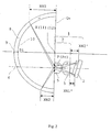
- Fig. 6 is an illustration to show the positional relationships within the outer limits 7, 7 of the field of view of the objective optical system 3, a jet orifice of a nozzle 30 for applying a substance in liquid form, and an observation target region 32 of the capsule-type endoscope 40 of the modification to Embodiment 1 shown in Figs. 5(a) and 5(b).
- a tubular organ such as the small intestine, though which the capsule-type endoscope 40 passes
- the capsule-type endoscope 40 is moved along through the tubular organ by means of the peristaltic motion of the tubular organ. Therefore, a part of the outer surface 9 of the transparent cover 8 is in contact with the inner wall 33 of the tubular organ and is within the field of view of the objective optical system 3.
- the capsule-type endoscope shown in Fig. 6 is designed to expand the inner wall 33 of the tubular organ through which it passes for enabling a substance in liquid form to be sprayed onto the inner wall of the tubular organ.
- a jet orifice 31 of the nozzle 30 is provided outside the field of view of the objective optical system 3.
- the nozzle and jet orifice can be relatively near the optical axis of the objective optical system 3, as indicated by a nozzle 30' and a jet orifice 31' as shown in dashed lines.
- a substance in liquid form is pushed out from the tank 18 to the nozzle 30 by a spray control device associated with the tank. Liquid is ejected from the jet orifice 31 and sprayed onto the observation target region 32 within a region delimited by the midpoint and the far point of the depth of field.
- the spray target region and the jet orifice 31 are too distant from each other; therefore the liquid substance will be sprayed onto an excessively large region, thereby failing to put sufficient spray per unit area on the target region.
- ⁇ is larger than 75°, the spray target region and the jet orifice 31 are too close to each other; therefore, the spray will contact the outer surface 9 of the transparent cover 8 and portions of the target region will be insufficiently sprayed.
- the nozzle shown in Fig. 6 is provided outside of the field of view of the objective optical system.
- the nozzle can be positioned so that at least a portion of the nozzle is within the field of view, if this does not interfere with the observation of a target region within the field of view. This is actually the preferred situation since it allows the spraying of the substance in liquid form to be observed within the field of view.
- a light absorbing black coating can be applied to the nozzle surface so that illumination light that would otherwise be reflected by the nozzle and cause flare within the field of view is minimized.
- Fig. 7 shows an embodiment of the capsule-type endoscope in which the jet orifice of the nozzle is positioned within the field of view of the objective optical system.
- the jet orifice 31 of the nozzle 30 of the capsule-type endoscope shown in Fig. 6 is provided at a position that is within the field of view of the objective optical system 3 and where it does not interfere with the observation of a target region within the field of view.
- the nozzle 30 and tank 18 can be formed as a unit that is detachably attachable to the capsule-type endoscope. In this way, the tank may be easily filled with a substance in liquid form, such as a solution. Further, when delivery of a substance to a target region is not required, the tank can be removed and, in its place, an extra power unit 42 can be mounted for prolonged observations.
- a capsule-type endoscope may be provided with a delivery tube having a puncture needle at one end that can be used when a substance in liquid form (such as a coloring agent or a drug) is desired to be injected into a living tissue.
- a substance in liquid form such as a coloring agent or a drug
- the puncture needle is penetrated into the living tissue at a position that is within the field of view of the objective optical system, and the substance in liquid form is injected via the delivery tube from the tank within the capsule.
- a projection port for the puncture needle should be positioned within the field of view of the objective optical system so that the tip of the puncture needle can be observed before the tip of the puncture needle is inserted into the living tissue.
- Fig. 8 shows an exemplary structure of a capsule-type endoscope that is provided with a solution delivery tube having a puncture needle at one end of the solution delivery tube.
- a projection port 34 for the puncture needle is provided at a position that is outside the outer limits 7 of the field of view of the objective optical system 3, but the tip of the puncture needle 35 is inside the field of view so that the insertion position of the puncture needle may be observed before the puncture needle is actually inserted into the living tissue.
- the puncture needle projection port 34 is designed to expand the inner wall 33 of a tubular organ, and thereby create an empty space between the puncture needle projection port 34 and the observation target region 32 that is within the field of view of the objective optical system.
- the positional relationship between the puncture needle 35 and the observation target region 32 of the living tissue may be determined before the tip of the puncture needle 35 is inserted into the observation target region 32. Therefore, the puncture needle tip may be prevented from puncturing the living tissue at an unintended point, and the puncture needle tip may be prevented from extending entirely through the living tissue.
- the puncture needle 35 may be stored inside the capsule and pushed out of the projection port 34 by a mechanism when the capsule-type endoscope approaches the observation target region 32 within the outer limits 7 of the field of view.
- the puncture needle 35 is provided with markings, which may be in different colors, at regular intervals from its tip that may be observed via a monitor to determine the depth that the tip of the puncture needle 35 has been inserted into the observation target region 32.
- the projection port 34 of the puncture needle, a puncture needle storage part 44, and a mechanism 37 for pushing out the puncture needle may be formed as a unit that may be detachably attached to the capsule-type endoscope.
- an electrical connection 38 be provided at the joint between the capsule and the detachable unit so that power is supplied from the capsule to the mechanism 37 for pushing out the puncture needle.
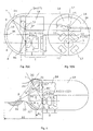
- Fig. 9 is an illustration to show another exemplary structure of a nozzle 30, as well as of a puncture needle projection port 34.
- the nozzle 30 and the puncture needle projection port 34 project through the transparent cover 8.
- the nozzle 30 is connected to the tank 18 through the transparent cover 8 at a position that is outside the outer limits 7, 7 of the field of view of the objective optical system.
- a jet orifice 31 is provided within the outer limits 7, 7 of the field of view of the objective optical system.
- the puncture needle projection port 34 is positioned so that the puncture needle protrudes through the transparent cover 8 at a point that is outside the outer limits 7, 7 of the field of view of the objective optical system.
- a delivery tube 36 that is connected to the puncture needle 35 may be connected to another tank (not shown).
- the front surface of the transparent cover 8 is designed so that a space exists between the puncture needle projection port 34 and the observation target region 32 of the living tissue. This enables the positional relationship between the puncture needle 35 and the living tissue to be observed. It is desired that the positional relationship between the image pickup unit and the inner surface of the transparent cover 8 satisfy Condition (1) above, but this is not required.
- Fig. 10 is an illustration to explain the operation of a capsule-type endoscope system for observing the inner wall of the digestive tract.
- the equipment enclosed by the dotted lines is an image display system 25 that is provided externally of the patient.
- a patient 41 is dressed in specifically designed clothing for externally controlling the orientation of the capsule-type endoscope 40 moving within the digestive tract 21.
- electromagnetic induction units not shown in the figure, may be used for this purpose.
- Image signals that are wirelessly transmitted from a communication unit that is positioned within the capsule-type endoscope 40 are received by a communication device 22 that is provided externally of the patient.
- the communication device 22 may be connected to a personal computer 24 for processing the image signals.
- the images that are processed by the personal computer 24 may be displayed on a monitor 23.
- the personal computer 24 is also provided with a memory device for storing the image signals.
- a target symbol 26 can be marked at a point ("x" in the figure) where the center line of the jet orifice 31 intersects an object to be viewed (i.e., the inner wall of the digestive tract 21). In this manner, one can ensure that a substance in liquid form is accurately sprayed onto an observation target region 32 (such as a possible lesion) within the field of view of the objective optical system.
- the observation target region 32 is captured by the image pickup unit between the far point and the mid point of the depth of field of the objective optical system.
- the orientation of the capsule-type endoscope 40 may be controlled so that the target symbol 26 overlaps the observation target region 32.
- a series of operations, including the display of the target symbol 26, the orientation control of the capsule-type endoscope 40, and the spraying of a substance in liquid form can be executed using one or more of a keyboard, a mouse, and a joy stick that are connected to the personal computer 24.
- the personal computer 24 may be used for tracking and controlling the capsule-type endoscope.
- the personal computer 24 may function to automatically control a series of operations, such as automatic tracking of the capsule-type endoscope and the delivery of a substance that is sprayed onto an intended target region.
- an observer may view images from the capsule-type endoscope that are displayed on the monitor 23 and may move a cursor over the observation target region 32 so as to specify automatic tracking of a target and the commencement of an automatic spray function.
- the personal computer 24 may provide the function of analyzing the morphology and color tone of an object captured by the image pickup unit. Screening for particular lesion patterns stored in the memory of the personal computer 24 may be performed concurrently with image processing and automatic target tracking.
- a substance in liquid form (such as a coloring agent or a drug) may be sprayed from the jet orifice 31 when the observation target region 32 and the target symbol 26 overlap on the monitor 23 in the course of automatic tracking.
- an indication to draw the observer's attention may be displayed on the monitor 23 when a lesion that may become a tracking target is first identified.
- the observer can cancel the automatic tracking operation by, for example, using a keyboard that is connected to the personal computer 24.
- the personal computer 24 may be provided with an image processing function so as to determine from captured images the depth that a puncture needle has been inserted into a living tissue after it first contacts the surface of a living tissue and so as to display the result on a monitor.
- a marking 39 (such as an "x") can be displayed at a position where the tip of the puncture needle will make contact with the living tissue surface, based on the positional relationship between the puncture needle projection port 34, the position of the observation target region 32 of the living tissue and the moving direction of the puncture needle.
- the observation target region 32 that is sprayed with a substance gradually approaches the objective optical system 3 and makes contact with the outer surface 9 of the transparent cover 8 near the near point of the depth of field of the objective optical system 3. Therefore, it is desired that the image pickup unit 1, which includes the objective optical system 3 and the image pickup element 2, has its highest resolution for objects near the outer surface 9 of the transparent cover 8 so that the region 32' can be viewed very clearly and a diagnosis made of the region 32'.
- R 1 ⁇ 5 lines per mm R 2 ⁇ 1 line per mm where R1 is the resolution on the optical axis at positions between the most object-side surface of the objective optical system and the point of intersection of the optical axis of the objective optical system with the outer surface of the transparent cover; and R2 is the resolution, as will be defined below, on the optical axis at positions between the most object-side surface of the objective optical system and the far point of the depth of field of the objective optical system.
- a resolution of 5 lines/mm or higher means that the contrast of black/white line pairs having a width of 0.2 mm is 10% or more on the monitor.
- a resolution of 1 line/mm or higher means that the contrast of black/white line pairs having a width of 0.5 mm is 10% or more on the monitor.
- Villi are small projections that extend from the wall of the small intestine.
- Villi are approximately 0.2 to 0.5 mm in width; therefore a resolution higher than this is required for good observation.
- the image pickup unit 1 has a resolution of 1 line/mm or higher for an object point distance B1
- the observation target region 32 can be easily found at the far point of the field of view when displayed on the monitor 23.
- the image pickup unit 1 is provided with an image pickup element 2 and objective optical system 3 that satisfies the following Conditions (4) - (6): 80 ⁇ IH / P ⁇ 500 80 ⁇ FL / P ⁇ 500 400 ⁇ Fno / P ⁇ 3000
- IH is the distance (in mm) between the center and the point most distant from the center of the effective image pickup area of the light-receiving surface of the image pickup element
- P is the horizontal pixel pitch (in mm) of the image pickup element
- FL is the focal length (in mm) of the objective optical system
- Fno is the effective F-number of the objective optical system.
- a capsule-type endoscope having an outer diameter of approximately 10 mm it is preferred for a capsule-type endoscope having an outer diameter of approximately 10 mm to have an object point distance A1 of 3 mm and an object point distance B1 of 50 mm.
- the objective optical system 3 consists of two positive lens elements in the disclosed embodiments of the present invention.
- the objective optical system 3 of the capsule-type endoscope of the present invention is not restricted to such a lens structure.
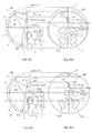
- Figs. 11(a) - 14(b) are illustrations of cross-sections of the front portion of the capsule-type endoscope according to Embodiment 2, and three possible modifications to Embodiment 2, of the present invention.
- Fig. 11(a) is a cross-section of a front portion of the capsule-type endoscope of Embodiment 2 as viewed from the side
- Fig. 11(b) is a cross-section of a front portion of the capsule-type endoscope of Embodiment 2 as viewed from the front.
- the inner surface 10 of the transparent cover 8 is spherical.
- the center of curvature 11 of the inner surface 10 of the transparent cover 8 is on the object side of a line 17 that passes through the center Pc of the entrance pupil of the objective optical system 3 and is orthogonal to the optical axis 4 of the objective optical system 3.
- the objective optical system 3 is provided in such a manner that the entrance pupil thereof is in the same plane as a plane Qm that contains the light emitting surface(s) 14 (see Fig. 12(a)) of the illumination light source(s) that form the illumination means 13.
- Points that happen to be coincident in the figures are labeled with multiple labels, with the second label listed in parenthesis.
- P is the intersection with a plane Qm of a line drawn from the center Pc of the entrance pupil of the objective optical system 3 so as to be perpendicular to the plane Qm.
- P and Pc are coincident and the position thereof is labeled P(Pc).
- three illumination light sources of the illumination means 13 are provided outside the reflected image range 15 of the entrance pupil of the objective optical system 3 when the image of the entrance pupil is projected via the inner surface 10 of the transparent cover 8 back onto the plane Qm.
- Figs. 12(a) and 12(b) show a first possible modification to Embodiment 2, with Fig. 12(a) being a cross-section of a front portion of the capsule-type endoscope according to the first possible modification of Embodiment 2 as viewed from the side, and Fig. 12(b) being a cross-section of a front portion of the capsule-type endoscope according to the first possible modification of Embodiment 2 as viewed from the front.
- the inner surface 10 of the transparent cover 8 is spherical.
- the center of curvature 11 of the inner surface 10 of the transparent cover 8 is on the image side of a line 17 that passes through the center Pc of the entrance pupil of the objective optical system 3 and is orthogonal to the optical axis 4 of the objective optical system 3.
- the objective optical system 3 is positioned so that the entrance pupil plane thereof lies in the same plane as the plane Qm that contains the light emitting surfaces 14 of the illumination light sources that form the illumination means 13.
- three illumination light sources form the illumination means 13 and these illumination light sources are provided outside the reflected image range 15 of the entrance pupil of the objective optical system 3.
- the center of curvature 11 of the portion of the inner surface 10 of the transparent cover 8 that is within the field of view of the objective optical system 3 is in a sector (among the four sectors delineated by the intersection of lines 7m and 7n when these lines are extended backward as shown in Fig. 12(a)) that does not include the optical axis of the objective optical system 3.
- the center of curvature 11 of the inner surface 10 of the transparent cover 8 coincides with the center of curvature of the portion of the inner surface 10 of the transparent cover 8 that is within the field of view of the objective optical system 3.
- the center of curvature 11 of the inner surface 10 of the transparent cover 8 coincides with the center of curvature of the portion of the inner surface 10 of the transparent cover 8 that is within the field of view of the objective optical system 3.
- the reflected image range 15 (defined above) of the entrance pupil of the objective optical system 3 will be larger than desired and thus will not leave a sufficient space for providing the illumination light source(s) that form the illumination means 13.
- FIGs. 15(a) and 15(b) are illustrations to show exemplary structure of a capsule-type endoscope according to the present invention so as to clarify the differences between the present invention versus prior art capsule-type endoscopes, with Fig. 15(a) being a cross-section of a front portion of the capsule-type endoscope as viewed from the side, and Fig. 15(b) being a cross-section of a front portion of the capsule-type endoscope as viewed from the front.
- the center of curvature 11 of the inner surface 10 of the transparent cover 8 is in a sector (among the four sectors delineated by the intersection of the lines 7m and 7n when these lines are extended backward as shown in Fig. 15(a)) that contains the optical axis of the objective optical system 3 and is on the object side of the center Pc of the entrance pupil of the objective optical system 3.
- the lines 7n and 7m are drawn from the center of the entrance pupil of the objective optical system to the points Sn and Sm that define the outer limits of the field of view of the objective optical system cross-section (depicted in Fig.
- the line 7m is on the image side (i.e., is to the right in Fig. 15(a)) of the line 19m that connects the center of curvature 11 to the outer boundary point Sm
- the line 7n is on the image side of the line 19n that connects the center of curvature 11 to the outer boundary point Sn (Sm and Sn are as defined previously).
- the light reflected at the point Sm proceeds toward the object side (i.e., to the left in Fig. 15(a)) of the line 19m that connects the center of curvature 11 to the outer boundary point Sm.
- the light reflected at the outer boundary point Sn also proceeds toward the object side of the line 19n that connects the center of curvature 11 to the outer boundary point Sn of the field of view in the plane of Fig. 15(a).
- Fig. 15(b) illustrates the reflected image range 15 (as defined above) of the entrance pupil of the objective optical system 3 onto the plane Qm that contains the light emitting surface(s) of the light source(s) that form the illumination means 13.
- Figs. 16(a) and 16(b) show another exemplary structure of a capsule-type endoscope according to the present invention so as to clarify the differences between the present invention versus prior art capsule-type endoscopes, with Fig. 16(a) being a cross-section of a front portion of the capsule-type endoscope as viewed from the side, and Fig. 16(b) being a cross-section of a front portion of the capsule-type endoscope as viewed from the front.
- the center of curvature 11 of the inner surface 10 of the transparent cover 8 is in a sector (among the four sectors delineated by the intersection of the lines 7m and 7n when these lines are extended backward as shown in Fig.
- the line 7m is on the object side (i.e., is to the left in Fig. 16(a)) of the line 19m that connects the center of curvature 11 to the outer boundary point Sm
- the line 7n is also on the object side of the line 19n that connects the center of curvature 11 to the outer boundary point Sn, where both Sm and Sn are as defined previously.
- the light reflected at the outer boundary point Sn also proceeds toward the image side of the line 19n that connects the center of curvature 11 to the outer boundary point Sn of the field of view in the plane of the figure.
- the reflected image range 15 of the entrance pupil of the objective optical system 3 will become excessively large on the plane Qm that contains the light-emitting surface(s) of the light source(s) that form the illumination means 13 and will overlap with the objective optical system 3, as shown in Fig. 16(b).
- a capsule-type endoscope embodiment in which the inner surface 10 of the transparent cover is spherical, that the center of curvature 11 of the inner surface 10 of the transparent cover 8 is in a sector (among the four sectors defined by the lines 7m and 7n when these lines are extended backward as shown in Fig. 16(b)) that does not contain the optical axis of the objective optical system.
- center of curvature 11 of the inner surface 10 of the transparent cover 8 and the center Pc of the entrance pupil of the objective optical system 3 are positioned so as to satisfy the above Condition (1).
- the objective optical system 3 When the upper limit of Condition (1) is not satisfied, the objective optical system 3 will be too close to the vertex St of the inner surface 10 of the transparent cover 8 and not leave a sufficient space to accommodate the illumination light source(s) of the illumination means 13. When the lower limit of the Condition (1) is not satisfied, the objective optical system 3 will be too far away from the vertex St of the inner surface 10 of the transparent cover 8, thereby increasing the entire capsule length.
- Figs. 13(a) and 13(b) and Figs. 14(a) and 14(b) show second and third possible modifications to Embodiment 2, with Figs. 13(a) and 14(a) being cross sections as viewed from the side, with the plane of the cross-section including the optical axis of the objective optical system and the vertex St of the inner surface of the transparent cover, and Figs. 13(b) and 14(b) being cross sections as viewed from the front.
- the inner surface 10 of the transparent cover 8 is an aspheric surface wherein the curvature increases with increasing distance from the vertex St of the inner surface.
- the inner surface 10 of the transparent cover 8 is an aspheric surface wherein the curvature decreases with increasing distance from the vertex St of the inner surface.
- the transparent cover 8 and the objective optical system 3 are positioned as follows: the curvature (curvature is defined as 1 divided by the radius of curvature R at the point of interest) at the points Sm and Sn (both as defined previously) is obtained and the centers of curvature OA and OB of spherical surfaces having a curvature of 1/R are positioned in a sector (among the four sectors delineated by the lines 7m and 7n when these lines are extended backward as shown in Figs. 13(a) and 14(a)) that does not contain the optical axis of the objective optical system.
- the objective optical system 3 is positioned so that the point of intersection X with the plane Qm of a line drawn from the vertex St perpendicular to the plane Qm (St and Qm are as defined previously) is on a line that connects the point P and the center 16 of the reflected image range 15.
- multiple illumination light sources are provided and are positioned outside the reflected image range 15.
- a sufficient space for providing the image pickup unit 1 while using multiple illumination light sources is ensured even if the inner surface 10 of the transparent cover 8 is aspheric. Therefore, a small-sized, capsule-type endoscope can be provided that prevents illumination light that is reflected by the inner surface 10 of the transparent cover 8 from causing flare in the objective optical system 3.
- Fig. 17 shows a cross-section of a front portion of a capsule-type endoscope according to Embodiment 3 of the present invention, as viewed from the side. More specifically, it illustrates a cross section that contains the optical axis 4 of the objective optical system 3 and the vertex St of the inner surface 10 of the transparent cover 8, and shows the imaging of an object point that is positioned on the outer surface 9 of the transparent cover 8 at the outer limits of the field of view of the objective optical system 3.
- the image pickup unit 1 of the capsule-type endoscope of Embodiment 3 includes an objective optical system 3 having lens components 5, 5 (which may each consist of a single lens element), a diaphragm (not shown), a lens frame (not shown), a spacer ring (not shown), an image pickup element 2, and an image pickup element frame (not shown).
- lens components 5, 5 which may each consist of a single lens element
- a diaphragm not shown
- a lens frame not shown
- a spacer ring not shown
- an image pickup element 2 an image pickup element frame
- the center of the field of view of the objective optical system 3 is positioned off the longitudinal axis of the capsule; thus, the distance between the most object-side surface of the objective optical system 3 and the outer surface 9 of the transparent cover 8 varies, depending on the viewing direction. This causes the image position for each object point to shift. Therefore, if the image pickup surface of the image pickup element 2 is positioned orthogonal to the optical axis as in prior art capsule-type endoscopes, objects that are in contact with the outer surface of the transparent cover 8 at the outer limits of the field of view of the objective optical system 3 will be partially out of focus, making observations difficult.
- the image pickup element 2 is tilted so as to be non-orthogonal to the optical axis of the objective optical system 3 in such a manner that the image pickup surface is positioned at the image positions ObA' and ObB', which correspond to the distances ObA and ObB between the most object-side surface of the objective optical system 3 and the outer surface 9 of the transparent cover 8 at the outer limits of the field of view of the objective optical system 3.
- capsule-type endoscope having such a structure, focal shifts on the image plane caused by differences in object point distances to the outer surface 9 of the transparent cover 8 in different viewing directions can be corrected, and a small-sized, capsule-type endoscope that allows for clear observation of objects that are in contact with the outer surface 9 of the transparent cover 8 can be realized.
- the tilt of the image pickup element 2 can be adjusted relative to the optical axis of the objective optical system 3 in such a manner that the diameter of a light flux on the image pickup surface extends over approximately four pixels for any viewing direction, as this yields images that are practically in focus.
- Fig. 18 shows the front portion of a capsule-type endoscope according to Embodiment 4 of the present invention and is for explaining the image-formation of an object point on the outer surface 9 of the transparent cover 8 at the outer limits of the field of view of the objective optical system 3 for this embodiment.
- the plane of the figure is a cross-section that contains the optical axis 4 of the objective optical system 3 and the vertex St of the inner surface 10 of the transparent cover 8.
- the capsule-type endoscope of Embodiment 4 is different from that of Embodiment 3 in that focal shifts on the image plane caused by differences in the object point distances as measured from the outer surface 9 of the transparent cover 8 in different viewing directions are corrected without having to tilt the image pickup element.
- the center of the field of view of the objective optical system 3 is positioned off the longitudinal axis of the capsule.
- the outer surface 9 of the transparent cover 8 is approximately symmetrically situated about the optical axis 4 of the objective optical system 3, and the vertex St of the inner surface of the transparent cover is offset from the optical axis 4 of the objective optical system 3.
- the outer surface 9 of the transparent cover 8 is spherical in shape.
- the distance between the center of curvature 12 of the outer surface 9 of the transparent cover 8 and the optical axis 4 of the objective optical system is 0.4 mm.
- Figs. 19(a) and 19(b) show the front portion of a capsule-type endoscope according to Embodiment 5 of the present invention, with Fig. 19(a) being a cross section (of a front portion of the capsule-shaped endoscope as viewed from the side) that contains the optical axis 4 of the objective optical system 3 and the vertex St of the inner surface 10 of the transparent cover 8, and Fig. 19(b) being a cross-section of a front portion of the capsule-shaped endoscope as viewed from the front.
- Fig. 19(a) illustrates forming images of object points on the outer surface 9 of the transparent cover 8 at the outer limits of the field of view of the objective optical system 3.
- Fig. 19(a) illustrates forming images of object points on the outer surface 9 of the transparent cover 8 at the outer limits of the field of view of the objective optical system 3.
- Fig. 19(a) illustrates forming images of object points on the outer surface 9 of the transparent cover 8 at the outer limits of the field of
- 19(b) shows the positional relationships, within a plane Qm that contains the light emitting surface(s) of the illumination light source(s) that form an illumination means, of the centers of curvature 11 and 12 of the inner and outer surfaces 10 and 9, respectively, of the transparent cover 8 and the reflected image range 15 (as defined previously) of the entrance pupil of the objective optical system.
- the center of curvature 12 of the outer surface 9 of the transparent cover 8 (which lies on the longitudinal axis of the capsule) is offset relative the optical axis 4 of the objective optical system, as well as relative to the center of curvature 11 of the inner surface 10 of the transparent cover 8, and one of the optical elements 5, 5 forming the objective optical system 3 is de-centered in order to compensate for object points at the outer surface of the transparent cover in different viewing directions being at different object distances from the entrance pupil of the objective optical system.
- focal shifts on the image plane caused by differences in the object point distances to the outer surface 9 of the transparent cover 8 in different viewing directions can be corrected even if the center of the field of view of the objective optical system 3 is positioned away from the longitudinal axis of the capsule.
- Figs. 20(a) and 20(b) show cross sections of the front portion of a capsule-type endoscope according to Embodiment 6 of the present invention, with Fig. 20(a) illustrating a cross section that contains the optical axis 4 of the objective optical system 3 and the vertex St of the inner surface 10 of the transparent cover 8 as viewed from the side, and Fig. 20(b) illustrating a cross-section as viewed from the front.
- Fig. 20(a) illustrates forming images of object points on the outer surface 9 of the transparent cover 8 at the outer limits of the field of view of the objective optical system 3.
- Fig. 20(a) illustrates forming images of object points on the outer surface 9 of the transparent cover 8 at the outer limits of the field of view of the objective optical system 3.
- Fig. 20(a) illustrates forming images of object points on the outer surface 9 of the transparent cover 8 at the outer limits of the field of view of the objective optical system 3.
- the inner surface 10 of the transparent cover 8 of Embodiment 6 is spherical.
- the center of curvature 11 of the inner surface 10 of the transparent cover 8 is on a line 17 that passes through the center Pc of the entrance pupil of the objective optical system 3 and is orthogonal to the optical axis 4 of the objective optical system 3.
- the entrance pupil of the objective optical system 3 coincides with the most object-side surface of the lenses 5, 5 that form the objective optical system 3.
- the objective optical system 3 is positioned so that the entrance pupil plane thereof is in the same plane as the plane Qm that contains the light emitting surfaces 14 of the illumination light sources that form the illumination means 13.
- the illumination light sources that form the illumination means 13 are evenly positioned around the optical axis of the objective optical system.
- the following Condition (7) is satisfied: PX > ( ⁇ L / 2 ) + ( ⁇ D ) where PX is the distance, on the plane Qm, between the intersection points P and X, where P is the intersection with the plane Qm of the optical axis of the objective optical system, and X is the intersection with the plane Qm of a line drawn from the vertex St of the inner surface of the transparent cover that is perpendicular to the plane Qm; ⁇ L is the outer diameter of the most object-side lens component of the objective optical system; and ⁇ D is the smallest distance between the center of an illumination light source and its outer periphery.
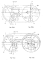
- Figs. 21(a) and 21(b) show cross sections of the front portion of a capsule-type endoscope according to Embodiment 7 of the present invention, with Fig. 21(a) illustrating a cross section that contains the optical axis 4 of the objective optical system 3 and the vertex St of the inner surface 10 of the transparent cover 8 as viewed from the side, and Fig. 21(b) illustrating a cross-section as viewed from the front.
- Fig. 21(a) illustrates forming images of object points on the outer surface 9 of the transparent cover 8 at the outer limits of the field of view of the objective optical system 3.
- Fig. 21(a) illustrates forming images of object points on the outer surface 9 of the transparent cover 8 at the outer limits of the field of view of the objective optical system 3.
- Fig. 21(a) illustrates forming images of object points on the outer surface 9 of the transparent cover 8 at the outer limits of the field of view of the objective optical system 3.
- the inner and outer surfaces 10 and 9 of the transparent cover 8 in the capsule-type endoscope of Embodiment 7 are both ellipsoidal.
- the coordinates of the focal points (0, 2.48) of the ellipsoidal transparent cover 8 are provided such that the center 11 of the inner surface 10 is the origin.
- the center 11 of the inner surface 10 is the center of the ellipsoid and is positioned at the intersection of the major and minor axes of the ellipsoid.
- the reflected image range 15 of the entrance pupil of the objective optical system 3 projected via the inner surface 10 of the transparent cover 8 is as shown in Fig. 21(b).
- the center 16 of the reflected image range 15 is positioned along a line 17 in the plane Qm that connects the points P(Pc) and X, where P and X are as defined above.
- the outer diameter of the capsule can be reduced from 12 mm, as in a prior art capsule-type endoscope, to 10.85 mm (as shown by the hatched area in Fig. 21(b)).
- the capsule-type endoscope of the present invention prevents light that is emitted by the illumination means 13 and reflected by the inner surface 10 of the transparent cover 8 from reaching the entrance pupil of the objective optical system 3, thus preventing flare even though the inner surface 10 of the transparent cover 8 is ellipsoidal in shape, while providing a small-sized, capsule-type endoscope that provides clear images.
- a coordinate system can be established with the origin at the center Pc of the entrance pupil of the objective optical system 3, with the y-axis being along the line that connects the center Pc of the entrance pupil of the objective optical system and the center of curvature 11 of the inner surface 10 of the transparent cover 8, and the x-axis being along the line that passes through the center Pc of the entrance pupil of the objective optical system 3 and is orthogonal to the y-axis.
- the positive direction of the y-axis is in the direction from the origin to the center of curvature 11 of the inner surface 10 of the transparent cover 8.
- Fig. 24 is an illustration to explain a capsule-type endoscope system in which a marking can be displayed by analyzing the position where the tip of the puncture needle makes contact with a living tissue surface, based on the positional relationship between the puncture needle projection port, the living tissue, and the moving direction of the puncture needle.
Abstract
Description
- This application claims the benefit under 35 U.S.C. §119 of JP 2004-228170, filed August 4, 2004, the contents of which are hereby incorporated by reference.
- Conventional capsule-type endoscopes contain, for example, an objective optical system, an illumination means, an image pickup element, and a transmission means within a capsule-shaped shell. A cover member (hereinafter termed a transparent cover) that is generally spherical in shape and transparent within the field of view of the objective optical system seals these items within the capsule-shaped shell. Typically, a capsule-type endoscope having the above-discussed structure converts into signals in vivo images that are captured on a light- receiving surface of the image pickup element. These signals, of images that have been captured using light that has passed through the transparent cover and the objective optical system, are then transmitted externally by means of the transmission means. The transmitted signals are received by an external receiver device, and are then displayed on a display device for examination.
- Capsule-type endoscopes as discussed above have a problem in that illumination light emitted from the illumination means is partly reflected by the inner surface of the spherical transparent cover and enters the entrance pupil of the objective optical system, which causes flare and significantly deteriorates the image contrast.
- The inventions as disclosed, for example, in the following prior art patent documents have been proposed to prevent light that is reflected by the inner surface of the transparent cover from reaching the entrance pupil of the objective optical system and causing flare.
- Japanese Laid-Open Patent Application 2003-325441 discloses a capsule-type endoscope in which the transparent cover has a spherical inner surface and the center of the entrance pupil of the objective optical system coincides with the center of curvature of this surface. Light that is emitted from the illumination means and reflected by the inner surface of the transparent cover is prevented from reaching the entrance pupil of the objective optical system, thus preventing flare.
Also, Japanese Laid-Open Patent Publication 2003-501704 discloses an optical device in which the transparent cover has an ellipsoidal inner surface and multiple light sources that function as an illumination means are provided along a focal curve on the focal plane of the ellipsoid. Once again, the light that is emitted from the illumination means and reflected by the inner surface of the transparent cover is prevented from reaching the objective optical system and causing flare. - However, the capsule-type endoscope disclosed in Japanese Laid-Open Patent Application 2003-325441 requires that the illumination means be positioned around the objective optical system because of the structure that the center of the entrance pupil of the objective optical system coincides with the center of curvature of the inner surface of the transparent cover. This disadvantageously increases the size of the capsule-type endoscope.
- As noted above, the light emitting elements that are used as the illumination means of the optical device disclosed in Japanese Laid-Open Patent Publication 2003-501704 must be located on the focal curve. Consequently, in order to provide sufficient room in which to mount these light- emitting elements, the transparent cover has to be increased in size, which requires that the size of the capsule-type endoscope itself be larger.
- Furthermore, it is desired that the capsule-type endoscope described above provide a space for carrying a battery for ensuring sufficient operation time of the capsule-type endoscope or a tank for carrying a substance in liquid form. However, when an attempt is made to provide such a space in the prior art capsule-type endoscopes discussed above, the location of such a space must be such that no interference occurs between the objective optical system and the illumination means. This requirement tends to increase the size of the capsule-type endoscope.
- The present invention relates to a capsule-type endoscope that can be swallowed for an in vivo examination. The purpose of the present invention is to provide a capsule-type endoscope that can prevent light that is reflected by the inner surface of the transparent cover from causing flare in the objective optical system, even if the size of the capsule-type endoscope is decreased.
- Another purpose of the present invention is to provide a capsule-type endoscope that can prevent light that is reflected by the inner surface of the transparent cover from causing flare in the objective optical system while simultaneously providing a sufficient space for mounting either a tank for carrying a substance in liquid form (such as a coloring agent or drug) for applying to a target region of a patient or a battery for increasing the operating time of the capsule-type endoscope.
- The present invention will become more fully understood from the detailed description given below and the accompanying drawings, which are given by way of illustration only and thus are not limitative of the present invention, wherein:
- Figs. 1(a) and 1(b) are cross-sections of a front portion of a capsule-type endoscope as viewed from the side and front, respectively;
- Fig. 2 is a cross-section of a front portion of a capsule-type endoscope as viewed from the side that shows forming images of object points located on the outer surface of the transparent cover at the outer limits of the field of view of the objective optical system;
- Figs. 3(a) and 3(b) are illustrations which relate to
Embodiment 1 of the present invention, with Fig. 3(a) being a cross-section of a front portion of the capsule-type endoscope as viewed from the side, and Fig. 3(b) being a cross-section of the front portion of the capsule-type endoscope as viewed from the front; - Figs. 4(a) and 4(b) relate to a first possible modification to
Embodiment 1 of the present invention, with Fig. 4(a) being a cross-section of a front portion of the capsule-type endoscope as viewed from the side, and Fig. 4(b) being a cross-section of a front portion of the capsule-type endoscope as viewed from the front; - Figs. 5(a) and 5(b) relate to a second possible modification to
Embodiment 1 of the present invention, with Fig. 5(a) being a cross-section of a front portion of the capsule-type endoscope as viewed from the side, and Fig. 5(b) being a cross-section of a front portion of the capsule-type endoscope as viewed from the front; - Fig. 6 shows the positional relationships of the field of view of the objective optical
system of a capsule-type endoscope, a jet orifice of a nozzle for spraying a substance in liquid
form onto a target region, and the observation target region of the capsule-type endoscope according to the second possible modification toEmbodiment 1 shown in Figs. 5(a) and 5(b); - Fig. 7 shows an embodiment of the capsule-type endoscope in which the jet orifice of a nozzle is positioned within the field of view of the objective optical system;
- Fig. 8 shows an exemplary structure of a capsule-type endoscope that is provided with a delivery tube having a puncture needle at one end of the delivery tube;
- Fig. 9 shows another exemplary structure of a nozzle, as well as of a puncture needle projection port, with the capsule being shown in cross-section as viewed from the side;
- Fig. 10 is an illustration to explain the capsule-type endoscope system of the present invention that may be used to observe the inner wall of a person=s digestive tract;
- Figs. 11(a) and 11(b) illustrate
Embodiment 2 of the present invention, with Fig. 11(a) being a cross-section of a front portion of the capsule-type endoscope as viewed from the side, and Fig. 11(b) being a cross-section of a front portion of the capsule-type endoscope as viewed from the front; - Figs. 12(a) and 12(b) illustrate a first possible modification to
Embodiment 2 of the present invention, with Fig. 12(a) being a cross-section of a front portion of the capsule-type endoscope as viewed from the side, and Fig. 12(b) being a cross-section of a front portion of the capsule-type endoscope as viewed from the front; - Figs. 13(a) and 13(b) illustrate a second possible modification to
Embodiment 2 of the present invention, with Fig. 13(a) being a cross-section of a front portion of the capsule-type endoscope as viewed from the side, and Fig. 13(b) being a cross-section of a front portion of the capsule-type endoscope as viewed from the front; - Figs. 14(a) and 14(b) illustrate a third possible modification to
Embodiment 2 of the present invention, with Fig. 14(a) being a cross-section of a front portion of the capsule-type endoscope as viewed from the side, and Fig. 14(b) being a cross-section of a front portion of the capsule-type endoscope as viewed from the front; - Figs. 15(a) and 15(b) are illustrations to show exemplary structure of a capsule-type endoscope according to the present invention so as to clarify the differences between the present invention versus prior art capsule-type endoscopes, with Fig. 15(a) being a cross-section of a front portion of a capsule-type endoscope according to the present invention as viewed from the side, and Fig. 15(b) being a cross-section of a front portion of a capsule-type endoscope according to the present invention as viewed from the front;
- Figs. 16(a) and 16(b) show another exemplary structure of a capsule-type endoscope according to the present invention so as to clarify the differences between the present invention versus prior art capsule-type endoscopes, with Fig. 16(a) being a cross-section of a front portion of a capsule-type endoscope according to the present invention as viewed from the side, and Fig. 16(b) being a cross-section of a front portion of a capsule-type endoscope according to the present invention as viewed from the front;
- Fig. 17 relates to
Embodiment 3 of the present invention, and illustrates the imaging of object points that are on the outer surface of the transparent cover at the outer limits of the field of view of the objective optical system; - Fig. 18 relates to
Embodiment 4 of the present invention, and illustrates the imaging of object points that are on the outer surface of the transparent cover at the outer limits of the field of view of the objective optical system; - Figs. 19(a) and 19(b) relate to
Embodiment 5 of the present invention, with Fig. 19(a) being a cross-section of a front portion of the capsule-type endoscope as viewed from the side, and Fig. 19(b) being a cross-section of a front portion of the capsule-type endoscope as viewed from the front; - Figs. 20(a) and 20(b) relate to
Embodiment 6 of the present invention, with Fig. 20(a) being a cross-section of a front portion of the capsule-type endoscope as viewed from the side, and Fig. 20(b) being a cross-section of a front portion of the capsule-type endoscope as viewed from the front; - Figs. 21(a) and 21(b) relate to
Embodiment 7 of the present invention, with Fig. 21(a) being a cross-section of a front portion of the capsule-type endoscope as viewed from the side, and Fig. 21(b) being a cross-section of a front portion of the capsule-type endoscope as viewed from the front; - Figs. 22(a) and 22(b) show a capsule-type endoscope in which a nozzle and tank for carrying a substance in liquid form are constituted as a unit that is detachably attached to the capsule-type endoscope;
- Figs. 23(a) and 23(b) show a capsule-type endoscope in which a puncture needle projection port, a puncture needle storage part, and a mechanism for pushing out the puncture needle are constituted as a unit that is detachably attached to the capsule-type endoscope; and
- Fig. 24 is an illustration to explain a capsule-type endoscope system in which a marking can be displayed by analyzing the position where the tip of the puncture needle will make contact with a living tissue surface, based on the positional relationship between the puncture needle projection port, the living tissue, and the moving direction of the puncture needle.
- In the present invention, a capsule-type endoscope is provided with an image pickup unit that includes an objective optical system, an image pickup element, and an illumination light source. A transparent cover, that is transparent within the field of view of the objective optical system, seals these components within an external surface. At least within the field of view of the objective optical system, the inner surface of the transparent cover is spherical so as to have a center of curvature, the optical axis of the objective optical system is offset from the center of curvature of the transparent cover, and the following Condition (1) is satisfied:

where
L1 is the distance between the center of curvature of the inner surface of the transparent cover and the optical axis of the objective optical system;
R is the radius of curvature of the inner surface of the transparent cover; and
θ is the half-field angle of the objective optical system. - It is preferred in the capsule-type endoscope of the present invention that the light emitting surface(s) of the light sources that form an illumination means are positioned in a manner such that the light emitting surface(s) does (do) not overlap an image of the entrance pupil of the objective optical system when light rays are projected onto a plane Qm by being reflected by the inner surface of the transparent cover, where the plane Qm is defined as the plane containing the light emitting surface(s) of the illumination means.
- Furthermore, the capsule-type endoscope of the present invention is characterized by the fact that the optical axis of the objective optical system is non-orthogonal to the tangential plane of the inner surface of the transparent cover where it intersects same (hereinafter referred to simply as >not orthogonal to the inner surface of the transparent cover=), and at least one of the components of the image pickup unit is tilted so as to be non-orthogonal to the optical axis of the objective optical system or is de-centered relative to other components of the image pickup unit.
- The present invention provides a capsule-type endoscope that can prevent light that is reflected by the inner surface of the transparent cover from causing flare in the objective optical system, even in the case where the capsule size is reduced or while ensuring that there exists a space for mounting either a tank for carrying a substance in liquid form or a battery for increasing the operating time of the capsule-type endoscope. The present invention will first be discussed in general terms with reference to Figs. 1(a) and 1(b).
- Figs. 1(a) and 1(b) are sectional illustrations of a capsule-type endoscope according to one embodiment of the present invention as viewed from the side and front, respectively. In Figs. 1(a) and 1(b),
item 4 is the optical axis of the objectiveoptical system 3, and St is the vertex of theinner surface 10 of thetransparent cover 8. Here, the vertex St is a point on theinner surface 10 of thetransparent cover 8 at which the distance between two points Gn and En is largest. Gn is a point on theinner surface 10 of thetransparent cover 8 and En is the intersection of a normal from the point Gn to a plane that is orthogonal to the optical axis and tangential to the most object side surface (surface being nearest to an object) of the objectiveoptical system 3.Item 9 is the outer surface of the transparent cover, P(Pc) is the center of the entrance pupil of the objectiveoptical system 3, and P'c is the point of intersection of hypothetical light rays if emitted from the center Pc of the entrance pupil and reflected by theinner surface 10 of thetransparent cover 8. Qm is as defined above, namely, the plane containing the light emitting surface(s) of the illumination means, X is the point of intersection of a line drawn from the vertex St of the inner surface of the transparent cover normal to the plane Qm, and P' is the point of intersection of a normal line drawn from the point P=c to the plane Qm. Region 15 (herein termed the reflected image of the entrance pupil of the objective optical system) is defined by the outer limit of hypothetical light rays emitted from the center of the entrance pupil of the objectiveoptical system 3, when such hypothetical light rays are then reflected by theinner surface 10 of thetransparent cover 8 so as to be incident onto the plane Qm. - The capsule-type endoscope shown in Figs. 1(a) and 1(b) is an embodiment of the present invention in which the
inner surface 10 of thetransparent cover 8 is spherical. In the capsule-type endoscope shown in Figs. 1(a) and 1(b), the objectiveoptical system 3 is provided with the center Pc of its entrance pupil on a line 17 (in the plane Qm) that passes through the center ofcurvature 11 of theinner surface 10 of thetransparent cover 8 and is orthogonal to theoptical axis 4 of the objectiveoptical system 3. In Fig. 1(a), the dashed lines 7', 7' define the outer limits of the field of view of a prior art capsule-type endoscope in which the center Pc of the entrance pupil of the objectiveoptical system 3 coincides with the center ofcurvature 11 of theinner surface 10 of thetransparent cover 8. On the other hand, thesolid lines optical system 3 when the center Pc of the entrance pupil of the objectiveoptical system 3 is provided at a point that is laterally offset from the center ofcurvature 11, and when the above Condition (1) is satisfied. - The
outer surface 9 of thetransparent cover 8 has its center of curvature at 12. - In the
capsule-type endoscope shown in Figs. 1(a) and 1(b), the centers ofcurvature outer surfaces transparent cover 8 coincide. - Satisfying Condition (1) above enables the cross-section size of the capsule to be reduced by the area indicated by the shaded part in Fig. 1(b) while maintaining the same field of view of the objective optical system as in prior art capsule-type endoscopes.
- Further, the light emitting surface(s) of the illumination means 13 does (do) not overlap the reflected
image 15 of the entrance pupil of the objectiveoptical system 3 on the plane Qm, as can be seen in the capsule-type endoscope shown in Figs. 1(a) and 1(b). Thus, illumination light emitted from the illumination means 13 and reflected by the inner surface of thetransparent cover 8 does not reach the entrance pupil of the objectiveoptical system 3, thereby preventing flare. - When the upper limit of Condition (1) above is not satisfied, the objective
optical system 3 is too close to the vertex St of theinner surface 10 of thetransparent cover 8, failing to reserve a space for providing the illumination light source. On the other hand, when the lower limit of Condition (1) is not satisfied, the objectiveoptical system 3 is too far away from the vertex St of theinner surface 10 of thetransparent cover 8, unfavorably increasing the entire capsule length. - It is preferred in the capsule-type endoscope of the present invention that the objective optical system be provided in a manner such that its optical axis is non-orthogonal to the inner surface of the transparent cover, and at least one of the components of the image pickup unit tilted so as to be non-orthogonal to the optical axis of the objective optical system or is de-centered relative to other components of the image pickup unit.
- Fig. 2 is an illustration to explain another important feature of the capsule-type endoscope of the present invention. It shows object points on the
outer surface 9 of thetransparent cover 8 at the outer limits of the field of view of the objective optical system 3 (in a cross section that contains theoptical axis 4 of the objectiveoptical system 3 and the vertex St of theinner surface 10 of the transparent cover 8) being imaged by the objectiveoptical system 3. - Unlike conventional endoscopes, the capsule-type endoscope of the present invention does not have a mechanism for sending air into the organ during observation/diagnosis. Therefore, the digestive tract (i.e., the usual passageway of the capsule endoscope) is presumably contracted and thus at least partially blocks the field of view of the objective optical system of the capsule-type endoscope. In addition, when the capsule is moved within a living body (hereinafter sometimes referred to simply as a >body=) by means of peristaltic motion of a tubular organ, the capsule is subjected to uniform pressure by the inner wall of the tubular organ. The inner wall of the tubular organ is in contact with the outer surface of the capsule in the most stable manner and the inner wall of the tubular organ also surrounds the outer surface of the transparent cover along its curved surface. Therefore, it is desired that the image pickup unit be able to focus on an object point that is located on the
outer surface 9 of thetransparent cover 8. - The
image pickup unit 1 may be formed of an objectiveoptical system 3 havinglens components 5, 5 (which, as shown, may each consist of a lens element), a diaphragm (not shown), a lens frame (not shown), a spacing ring (not shown), animage pickup element 2, and an image pickup element frame (not shown). - As shown in Fig. 2, when the objective
optical system 3 is positioned with the center of its entrance pupil shifted from the center line of the capsule so that the optical axis of the objectiveoptical system 3 is non-orthogonal to the inner surface of thetransparent cover 8, the distance between the most object-side surface of the objectiveoptical system 3 and theouter surface 9 of thetransparent cover 8 varies, depending on the direction of viewing. This results in a shifting of the image position for each object point. Therefore, if the image pickup surface of theimage pickup element 2 is orthogonal to the optical axis of the objective optical system as in prior art capsule-type endoscopes, an object of interest, such as the inner surface of a tubular organ that is in contact with the outer surface of thetransparent cover 8, will have a portion that is not properly focused onto the surface of the image pickup element, and this will cause difficulty in observation. - In the capsule-type endoscope shown in Fig. 2, the
image pickup element 2 is tilted so as to be non-orthogonal to the optical axis of the objectiveoptical system 3 in such a manner that the image pickup surface is positioned at the image positions XN1', XN2' that correspond to the distances XN1, XN2 between the most object-side surface of the objectiveoptical system 3 and theouter surface 9 of thetransparent cover 8. In this way, focal shifts as a result of differences in the object point distance to theouter surface 9 of thetransparent cover 8 in different viewing directions is corrected. In this manner, a small-sized, capsule-type endoscope that allows for clear observations of an object, such as the inner wall of a tubular organ, that is in contact with theouter surface 9 of thetransparent cover 8 can be provided. - In lieu of, or in addition to, the image pickup unit being tiled as shown in Fig. 2, at least one of the components of the image pickup unit other than the image pickup element can be de-centered relative to other components of the image pickup unit. In this way, focal shifts as a result of differences in the object distance to the
outer surface 9 of thetransparent cover 8 in different viewing directions can be similarly corrected and clear images can be obtained. - Various embodiments of the capsule-type endoscope of the present invention will now be described in detail with reference to the drawings.
- Figs. 3(a) and 3(b) are illustrations which show the front portion of a capsule-type endoscope according to
Embodiment 1 of the present invention, with Fig. 3(a) being a cross-section of a front portion of the capsule-type endoscope as viewed from the side, and Fig. 3(b) being a cross-section of a front portion of the capsule-type endoscope as viewed from the front. Like items in the drawings have been similarly numbered throughout the drawings. The illumination means 13 may be formed of semiconductor-chip-type, light emitting diodes (hereinafter termed LEDs), that are provided at different positions within the capsule, and the capsule-type endoscope is provided with a cover that is transparent within the field of view of the objectiveoptical system 3 and that seals the capsule. The entrance pupil of the objectiveoptical system 3 coincides with the most object-side surface of thelens components optical system 3. Furthermore, the entrance pupil plane is on the same plane as the plane Qm that contains the light emitting surface(s) of the illumination means 13. A power supply battery and a transmission antenna for transmitting information, such as images, to a separate receiver device (not shown) are provided behind (i.e., on the image side of) the objectiveoptical system 3. - As in Fig. 1, the
inner surface 10 of thetransparent cover 8 is spherical, and the center ofcurvature 11 of theinner surface 10 of thetransparent cover 8 is on aline 17 that passes through the center Pc of the entrance pupil of the objectiveoptical system 3 and is orthogonal to theoptical axis 4 of the objectiveoptical system 3. Thelines optical system 3 so as to pass through the points Sm and Sn that are located on theinner surface 10 of the transparent cover and these lines define the outer limits of the field of view of the objectiveoptical system 3. - As mentioned above, the size of the capsule can be reduced relative to that of prior art capsule-type endoscopes by offsetting the optical axis of the objective optical system from the axial center of the capsule. In this embodiment, the offset amount is 0.76 mm for a prior art transparent cover having an outer diameter of 5.6 mm. In this way, the cross-sectional area of the capsule can be reduced (as shown by the hatched area illustrated in Fig. 3(b)) and the outer diameter of the capsule=s cylindrical surface can be reduced from 5.6 mm to 5.0 mm. The reflected
image range 15 of the entrance pupil of the objective optical system is defined herein as the intersection points with the plane Qm of hypothetical light rays that emerge from the center Pc of the entrance pupil of the objective optical system at the outer limits of the field of view of the objective optical system and are then reflected by the inner surface of the transparent cover onto the plane Qm. - The reflected image range 15 (defined above) may be determined by reverse ray tracing light rays entering the center Pc of the entrance pupil of the objective
optical system 3 from points on the inner surface of thetransparent cover 8 that are at the outermost periphery of the field of view. In other words, in Fig. 3(a), the reflectedimage range 15 of the entrance pupil of the objectiveoptical system 3 is determined by the light rays 7 that form the outer limits of the field of view of the objective optical system, if such rays were to be reversed, reflected by theinner surface 10 of thetransparent cover 8, and were then to be incident onto the plane Qm. - In the capsule-type endoscope of
Embodiment 1, four LEDs comprise the illumination means 13 and these LEDs are provided outside the reflectedimage range 15 of the entrance pupil of the objectiveoptical system 3. In addition, none of the optical axes of the LEDs is orthogonal to theinner surface 10 of thetransparent cover 8. The optical axis of each of the four LEDs passes through the center of its light-emitting surface and is orthogonal to the light-emitting, surface. When multiple light emitting surfaces form the illumination means 13, and when these surfaces do not lie in the same plane Qm, the objectiveoptical system 3 and each LED are positioned to satisfy Condition (1) above within the respective planes containing the light emitting surfaces of the illumination means 13. - With the capsule-type endoscope of
Embodiment 1 having the structure discussed above, a capsule-type endoscope can be provided that is reduced in size relative to that of prior art capsule-type endoscopes, while ensuring the same field of view. Moreover, light emitted from the illumination means 13 and reflected by the inner surface of thetransparent cover 8 can be prevented from entering the entrance pupil of the objectiveoptical system 3. Therefore, flare can be prevented so as to allow for observation of clear images. - Figs. 4(a) and 4(b) show a first possible modification to
Embodiment 1, with Fig. 4(a) being a cross-section of a front portion of the capsule-type endoscope as viewed from the side, and Fig. 4(b) being a cross-section of a front portion of the capsule-type endoscope as viewed from the front. In the capsule-type endoscope of the modification toEmbodiment 1 shown in Figs. 4(a) and 4(b), one of the illumination light sources (such as theillumination light source 13a) is provided with its optical axis orthogonal to theinner surface 10 of thetransparent cover 8. This modification toEmbodiment 1 will now be discussed in comparison with a prior art capsule-type endoscope having a transparent cover diameter of 8.3 mm, as indicated by the dashed lines in Fig. 4(a). By offsetting the optical axis of the objective optical system from the axial center of the capsule a distance of 1.7 mm, the outer diameter of the capsule's cylindrical surface can be reduced from 8.3 mm to 7.4 mm. As before, thelines optical system 3 so as to pass through the points Sm and Sn that are located on theinner surface 10 of thetransparent cover 8 and that define the outer limits of the field of view of the objectiveoptical system 3. - Figs. 5(a) and 5(b) show a second possible modification to
Embodiment 1, with Fig. 5(a) being a cross-section of a front portion of the capsule-type endoscope as viewed from the side, and Fig. 5(b) being a cross-section of a front portion of the capsule-type endoscope as viewed from the front. With the second possible modification toEmbodiment 1 as shown in Figs. 5(a) and 5(b), a space for mounting other members can be obtained without increasing the capsule size as compared with a prior art capsule-type endoscope. As a result, a capsule-type endoscope can be obtained that has space for atank 18 for carrying a substance in liquid form while preventing light that is reflected by the inner surface of thetransparent cover 8 from entering the entrance pupil of the objective optical system and causing flare. Instead of a tank for a carrying a substance in liquid form being mounted in the space for mounting other members, one of a battery to extend the operation time of the capsule endoscope, a wireless transmission/reception means, or a capacitor can be mounted. Other structures remain the same as for the capsule-type endoscope shown in Figs. 3(a) and 3(b), and therefore further explanation will be omitted. The capsule-type endoscope of this modified embodiment allows for providing one of a substance in liquid form (such as a coloring agent or a drug) to a lesion, an extended operating time of the image pickup system, improved reliability of the wireless communications, or another power source (such as a capacitor) within a small-sized, capsule-type endoscope. - In the case where a tank for delivery of a substance in liquid form to a lesion is provided, the capsule endoscope exterior is provided with a nozzle for spraying the substance in liquid form. When a possible lesion is found by observing the inner wall of an organ that is in the field of view of the objective optical system while the capsule-type endoscope moves along within tubular organs such as organs of the digestive tract, a substance such as a coloring agent can be sprayed on the region through the nozzle. Therefore, a jet orifice of the nozzle is directed in the viewing direction, and the field of view of the objective optical system and the spray range of the nozzle should overlap. It is further desired that the nozzle be at a position that does not obscure the observation of a target region within the field of view.
- Fig. 6 is an illustration to show the positional relationships within the
outer limits optical system 3, a jet orifice of anozzle 30 for applying a substance in liquid form, and anobservation target region 32 of the capsule-type endoscope 40 of the modification toEmbodiment 1 shown in Figs. 5(a) and 5(b). Presumably, the inside of a tubular organ (such as the small intestine, though which the capsule-type endoscope 40 passes) contacts the peripheral portion of the transparent cover of the capsule-type endoscope 40. The capsule-type endoscope 40 is moved along through the tubular organ by means of the peristaltic motion of the tubular organ. Therefore, a part of theouter surface 9 of thetransparent cover 8 is in contact with theinner wall 33 of the tubular organ and is within the field of view of the objectiveoptical system 3. - The capsule-type endoscope shown in Fig. 6 is designed to expand the
inner wall 33 of the tubular organ through which it passes for enabling a substance in liquid form to be sprayed onto the inner wall of the tubular organ. As shown in Fig. 6, which illustrates a cross-section of the capsule-type endoscope as viewed from the side, ajet orifice 31 of thenozzle 30 is provided outside the field of view of the objectiveoptical system 3. In addition, if the angle β between the center line of thejet orifice 31 and theoptical axis 4 of the objectiveoptical system 3 is made to lie in the range of 15° to 75°, the nozzle and jet orifice can be relatively near the optical axis of the objectiveoptical system 3, as indicated by a nozzle 30' and a jet orifice 31' as shown in dashed lines. A substance in liquid form is pushed out from thetank 18 to thenozzle 30 by a spray control device associated with the tank. Liquid is ejected from thejet orifice 31 and sprayed onto theobservation target region 32 within a region delimited by the midpoint and the far point of the depth of field. - If the angle β is smaller than 15°, the spray target region and the
jet orifice 31 are too distant from each other; therefore the liquid substance will be sprayed onto an excessively large region, thereby failing to put sufficient spray per unit area on the target region. On the other hand, if β is larger than 75°, the spray target region and thejet orifice 31 are too close to each other; therefore, the spray will contact theouter surface 9 of thetransparent cover 8 and portions of the target region will be insufficiently sprayed. - The nozzle shown in Fig. 6 is provided outside of the field of view of the objective optical system. However, the nozzle can be positioned so that at least a portion of the nozzle is within the field of view, if this does not interfere with the observation of a target region within the field of view. This is actually the preferred situation since it allows the spraying of the substance in liquid form to be observed within the field of view. In such a case, it is desired that the nozzle surface be processed so as to reduce the amount of light reflected by the nozzle. Alternately, a light absorbing black coating can be applied to the nozzle surface so that illumination light that would otherwise be reflected by the nozzle and cause flare within the field of view is minimized.
- Fig. 7 shows an embodiment of the capsule-type endoscope in which the jet orifice of the nozzle is positioned within the field of view of the objective optical system. The
jet orifice 31 of thenozzle 30 of the capsule-type endoscope shown in Fig. 6 is provided at a position that is within the field of view of the objectiveoptical system 3 and where it does not interfere with the observation of a target region within the field of view. As shown in Figs. 22(a) and 22(b) , thenozzle 30 andtank 18 can be formed as a unit that is detachably attachable to the capsule-type endoscope. In this way, the tank may be easily filled with a substance in liquid form, such as a solution. Further, when delivery of a substance to a target region is not required, the tank can be removed and, in its place, anextra power unit 42 can be mounted for prolonged observations. - A capsule-type endoscope may be provided with a delivery tube having a puncture needle at one end that can be used when a substance in liquid form (such as a coloring agent or a drug) is desired to be injected into a living tissue. In such a case, the puncture needle is penetrated into the living tissue at a position that is within the field of view of the objective optical system, and the substance in liquid form is injected via the delivery tube from the tank within the capsule. To accomplish this, a projection port for the puncture needle should be positioned within the field of view of the objective optical system so that the tip of the puncture needle can be observed before the tip of the puncture needle is inserted into the living tissue. This is to ensure that the puncture needle tip does not puncture at an unintended point and to ensure that the puncture needle tip does not extend entirely through, and thus beyond, the intended living tissue. A similar precaution can be taken for a puncture needle to be inserted into living tissue for collecting biopsy samples.
- Fig. 8 shows an exemplary structure of a capsule-type endoscope that is provided with a solution delivery tube having a puncture needle at one end of the solution delivery tube.
In the capsule-type endoscope in Fig. 8, aprojection port 34 for the puncture needle is provided at a position that is outside theouter limits 7 of the field of view of the objectiveoptical system 3, but the tip of thepuncture needle 35 is inside the field of view so that the insertion position of the puncture needle may be observed before the puncture needle is actually inserted into the living tissue. The punctureneedle projection port 34 is designed to expand theinner wall 33 of a tubular organ, and thereby create an empty space between the punctureneedle projection port 34 and theobservation target region 32 that is within the field of view of the objective optical system. - With such a structure, the positional relationship between the
puncture needle 35 and theobservation target region 32 of the living tissue may be determined before the tip of thepuncture needle 35 is inserted into theobservation target region 32. Therefore, the puncture needle tip may be prevented from puncturing the living tissue at an unintended point, and the puncture needle tip may be prevented from extending entirely through the living tissue. Thepuncture needle 35 may be stored inside the capsule and pushed out of theprojection port 34 by a mechanism when the capsule-type endoscope approaches theobservation target region 32 within theouter limits 7 of the field of view. Moreover, thepuncture needle 35 is provided with markings, which may be in different colors, at regular intervals from its tip that may be observed via a monitor to determine the depth that the tip of thepuncture needle 35 has been inserted into theobservation target region 32. - As shown in Figs. 23(a) and 23(b), the
projection port 34 of the puncture needle, a punctureneedle storage part 44, and amechanism 37 for pushing out the puncture needle may be formed as a unit that may be detachably attached to the capsule-type endoscope. In such a case, it is preferred that anelectrical connection 38 be provided at the joint between the capsule and the detachable unit so that power is supplied from the capsule to themechanism 37 for pushing out the puncture needle. - Fig. 9 is an illustration to show another exemplary structure of a
nozzle 30, as well as of a punctureneedle projection port 34. In this structure, thenozzle 30 and the punctureneedle projection port 34 project through thetransparent cover 8. Thenozzle 30 is connected to thetank 18 through thetransparent cover 8 at a position that is outside theouter limits jet orifice 31 is provided within theouter limits needle projection port 34 is positioned so that the puncture needle protrudes through thetransparent cover 8 at a point that is outside theouter limits delivery tube 36 that is connected to thepuncture needle 35 may be connected to another tank (not shown). The front surface of thetransparent cover 8 is designed so that a space exists between the punctureneedle projection port 34 and theobservation target region 32 of the living tissue. This enables the positional relationship between thepuncture needle 35 and the living tissue to be observed. It is desired that the positional relationship between the image pickup unit and the inner surface of thetransparent cover 8 satisfy Condition (1) above, but this is not required. - Fig. 10 is an illustration to explain the operation of a capsule-type endoscope system for observing the inner wall of the digestive tract. In Fig. 10, the equipment enclosed by the dotted lines is an
image display system 25 that is provided externally of the patient. Apatient 41 is dressed in specifically designed clothing for externally controlling the orientation of the capsule-type endoscope 40 moving within thedigestive tract 21. For example, electromagnetic induction units, not shown in the figure, may be used for this purpose. Image signals that are wirelessly transmitted from a communication unit that is positioned within the capsule-type endoscope 40 are received by acommunication device 22 that is provided externally of the patient. Thecommunication device 22 may be connected to apersonal computer 24 for processing the image signals. The images that are processed by thepersonal computer 24 may be displayed on amonitor 23. Thepersonal computer 24 is also provided with a memory device for storing the image signals. For example, atarget symbol 26 can be marked at a point ("x" in the figure) where the center line of thejet orifice 31 intersects an object to be viewed (i.e., the inner wall of the digestive tract 21). In this manner, one can ensure that a substance in liquid form is accurately sprayed onto an observation target region 32 (such as a possible lesion) within the field of view of the objective optical system. - During an observation while the capsule-
type endoscope 40 proceeds along within thedigestive tract 21, theobservation target region 32 is captured by the image pickup unit between the far point and the mid point of the depth of field of the objective optical system. The orientation of the capsule-type endoscope 40 may be controlled so that thetarget symbol 26 overlaps theobservation target region 32. A series of operations, including the display of thetarget symbol 26, the orientation control of the capsule-type endoscope 40, and the spraying of a substance in liquid form can be executed using one or more of a keyboard, a mouse, and a joy stick that are connected to thepersonal computer 24. - The
personal computer 24 may be used for tracking and controlling the capsule-type endoscope. For example, thepersonal computer 24 may function to automatically control a series of operations, such as automatic tracking of the capsule-type endoscope and the delivery of a substance that is sprayed onto an intended target region. With thepersonal computer 24 providing such a function, an observer may view images from the capsule-type endoscope that are displayed on themonitor 23 and may move a cursor over theobservation target region 32 so as to specify automatic tracking of a target and the commencement of an automatic spray function. Alternatively, thepersonal computer 24 may provide the function of analyzing the morphology and color tone of an object captured by the image pickup unit. Screening for particular lesion patterns stored in the memory of thepersonal computer 24 may be performed concurrently with image processing and automatic target tracking. A substance in liquid form (such as a coloring agent or a drug) may be sprayed from thejet orifice 31 when theobservation target region 32 and thetarget symbol 26 overlap on themonitor 23 in the course of automatic tracking. When automatically determining a tracking target by analyzing the morphology and color tone of the images captured by the image pickup unit, an indication to draw the observer's attention may be displayed on themonitor 23 when a lesion that may become a tracking target is first identified. - Should an observer determine by observing the received images that there is no need for spraying, the observer can cancel the automatic tracking operation by, for example, using a keyboard that is connected to the
personal computer 24. When using a capsule-type endoscope that is provided with a delivery tube and a puncture needle, thepersonal computer 24 may be provided with an image processing function so as to determine from captured images the depth that a puncture needle has been inserted into a living tissue after it first contacts the surface of a living tissue and so as to display the result on a monitor. Furthermore, a marking 39 (such as an "x") can be displayed at a position where the tip of the puncture needle will make contact with the living tissue surface, based on the positional relationship between the punctureneedle projection port 34, the position of theobservation target region 32 of the living tissue and the moving direction of the puncture needle. - As shown by the diagonal, broken lines in the region 32' of Fig. 6, the
observation target region 32 that is sprayed with a substance gradually approaches the objectiveoptical system 3 and makes contact with theouter surface 9 of thetransparent cover 8 near the near point of the depth of field of the objectiveoptical system 3. Therefore, it is desired that theimage pickup unit 1, which includes the objectiveoptical system 3 and theimage pickup element 2, has its highest resolution for objects near theouter surface 9 of thetransparent cover 8 so that the region 32' can be viewed very clearly and a diagnosis made of the region 32'. In other words, it is desired for the structure in Fig. 6 to satisfy the following Conditions (2) and (3):

where
R1 is the resolution on the optical axis at positions between the most object-side surface of the objective optical system and the point of intersection of the optical axis of the objective optical system with the outer surface of the transparent cover; and
R2 is the resolution, as will be defined below, on the optical axis at positions between the most object-side surface of the objective optical system and the far point of the depth of field of the objective optical system. - The term Aresolution@ (as will be defined below) is measured as follows. Pairs of black and white lines are captured by the image pickup unit and displayed on a monitor via a system for processing image signals transmitted from the solid-state image pickup element. The contrast I of the black/white line pairs on the monitor is obtained using the following Equation (A):

where
Imax and Imin are the maximum and minimum values of the black and white intensity profile, respectively. - >Resolution= is defined as the reciprocal of the width (in mm) of the black/white line pair when the contrast I, as set forth above, is 10%. Thus, "a resolution of 5 lines/mm or higher" means that the contrast of black/white line pairs having a width of 0.2 mm is 10% or more on the monitor. Similarly, a resolution of 1 line/mm or higher means that the contrast of black/white line pairs having a width of 0.5 mm is 10% or more on the monitor. When the
image pickup unit 1 has a resolution of 5 lines/mm or higher for an object point distance A1, the living tissue near the outer surface of the transparent cover can be enlarged on themonitor 23 for observation. Particularly, it is important for a capsule-type endoscope to allow for close-up observation of villi, which are small projections that extend from the wall of the small intestine. Villi are approximately 0.2 to 0.5 mm in width; therefore a resolution higher than this is required for good observation. When theimage pickup unit 1 has a resolution of 1 line/mm or higher for an object point distance B1, theobservation target region 32 can be easily found at the far point of the field of view when displayed on themonitor 23. - It is desired that the
image pickup unit 1 is provided with animage pickup element 2 and objectiveoptical system 3 that satisfies the following Conditions (4) - (6):


where
IH is the distance (in mm) between the center and the point most distant from the center of the effective image pickup area of the light-receiving surface of the image pickup element;
P is the horizontal pixel pitch (in mm) of the image pickup element;
FL is the focal length (in mm) of the objective optical system; and
Fno is the effective F-number of the objective optical system. - When the value of IH / P equals or exceeds 500 (i.e., does not satisfy the upper limit of Condition (4)), a larger depth of field cannot be obtained when used in combination with the objective optical system. On the other hand, when the value of IH/P does not satisfy the lower limit of Condition (4), a required resolution cannot be obtained near the near point of the depth of field.
- When the value of FL / P equals or exceeds 500 (i.e., does not satisfy the upper limit of Condition (5)), the depth of field will become small when used in combination with the objective optical system. On the other hand, when the value of FL / P does not satisfy the lower limit of Condition (5), it is difficult to obtain a desired resolution at the object point distance A1.
- When the value of Fno / P equals or exceeds 3000 (i.e., does not satisfy the upper limit of Condition (6)), the required resolution will exceed the optical diffraction limit, and thus high quality images will be unattainable even though the images are in focus. When the value of
Fno / P is 400 or less (i.e., does not satisfy the lower limit of Condition (6)), the depth of field will become small; a desired resolution will be obtained at the object point distance A1 while focal shifts will occur at the object point distance B1. - For example, it is preferred for a capsule-type endoscope having an outer diameter of approximately 10 mm to have an object point distance A1 of 3 mm and an object point distance B1 of 50 mm. The objective
optical system 3 consists of two positive lens elements in the disclosed embodiments of the present invention. However, the objectiveoptical system 3 of the capsule-type endoscope of the present invention is not restricted to such a lens structure. - Figs. 11(a) - 14(b) are illustrations of cross-sections of the front portion of the capsule-type endoscope according to
Embodiment 2, and three possible modifications toEmbodiment 2, of the present invention. Fig. 11(a) is a cross-section of a front portion of the capsule-type endoscope ofEmbodiment 2 as viewed from the side, and Fig. 11(b) is a cross-section of a front portion of the capsule-type endoscope ofEmbodiment 2 as viewed from the front. - In the capsule-type endoscope of
Embodiment 2 shown in Figs. 11(a) and 11(b), theinner surface 10 of thetransparent cover 8 is spherical. The center ofcurvature 11 of theinner surface 10 of thetransparent cover 8 is on the object side of aline 17 that passes through the center Pc of the entrance pupil of the objectiveoptical system 3 and is orthogonal to theoptical axis 4 of the objectiveoptical system 3. The objectiveoptical system 3 is provided in such a manner that the entrance pupil thereof is in the same plane as a plane Qm that contains the light emitting surface(s) 14 (see Fig. 12(a)) of the illumination light source(s) that form the illumination means 13. - Furthermore, in the capsule-type endoscope of
Embodiment 2 shown in Figs. 11(a) and 11(b), the objectiveoptical system 3 is positioned so that the point of intersection X with the plane Qm of a line drawn from the vertex St of theinner surface 10 of the transparent cover so as to be perpendicular to the plane Qm lies on the longitudinal axis of the capsule, and the point X is on a line that connects the intersection points P and P=. Points that happen to be coincident in the figures are labeled with multiple labels, with the second label listed in parenthesis. P is the intersection with a plane Qm of a line drawn from the center Pc of the entrance pupil of the objectiveoptical system 3 so as to be perpendicular to the plane Qm. Thus, in Fig. 11(a), P and Pc are coincident and the position thereof is labeled P(Pc). P= is the intersection with the plane Qm of a line drawn from the intersection point P'c so as to be perpendicular to the plane Qm. P=c is the intersection point of hypothetical light rays that emerge from the center Pc of the entrance pupil of the objectiveoptical system 3 and are reflected by theinner surface 10 of thetransparent cover 8 at the points Sm and Sn that define the outer limits of the field of view of the objectiveoptical system 3 in the plane (depicted in Fig. 11(a)) that contains the vertex St of the inner surface of the transparent cover and the optical axis of the objective optical system. In this embodiment, three illumination light sources of the illumination means 13 are provided outside the reflectedimage range 15 of the entrance pupil of the objectiveoptical system 3 when the image of the entrance pupil is projected via theinner surface 10 of thetransparent cover 8 back onto the plane Qm. - Figs. 12(a) and 12(b) show a first possible modification to
Embodiment 2, with Fig. 12(a) being a cross-section of a front portion of the capsule-type endoscope according to the first possible modification ofEmbodiment 2 as viewed from the side, and Fig. 12(b) being a cross-section of a front portion of the capsule-type endoscope according to the first possible modification ofEmbodiment 2 as viewed from the front. In this capsule-type endoscope, theinner surface 10 of thetransparent cover 8 is spherical. The center ofcurvature 11 of theinner surface 10 of thetransparent cover 8 is on the image side of aline 17 that passes through the center Pc of the entrance pupil of the objectiveoptical system 3 and is orthogonal to theoptical axis 4 of the objectiveoptical system 3. The objectiveoptical system 3 is positioned so that the entrance pupil plane thereof lies in the same plane as the plane Qm that contains thelight emitting surfaces 14 of the illumination light sources that form the illumination means 13. - Furthermore, in the possible modification to
Embodiment 2 shown in Figs. 12(a) and 12(b), the objectiveoptical system 3 is positioned such that the intersection X with the plane Qm of a line drawn from the vertex St of theinner surface 10 of the transparent cover perpendicular to the plane Qm is on a line that connects the points P and P=, where Qm, P and P= are as previously defined. In the possible modification shown in Figs. 12(a) and 12(b), three illumination light sources form the illumination means 13 and these illumination light sources are provided outside the reflectedimage range 15 of the entrance pupil of the objectiveoptical system 3. - In the capsule-type endoscope of the present invention according to
Embodiment 2 shown in Figs. 11(a) and 11(b), and the first possible modification shown in Figs. 12(a) and 12(b), four areas are defined by thelines optical axis 4 of the objectiveoptical system 3 and the vertex St of theinner surface 10 of thetransparent cover 8. Thelines optical system 3 so as to pass through the points Sm and Sn on theinner surface 10 of thetransparent cover 8 that define the outer limits of the field of view of the objective optical system in the cross-section (depicted in Fig. 12(a)) that contains the vertex St of the inner surface of the transparent cover and the center Pc of the entrance pupil of the objective optical system. As is apparent from Fig. 12(b), the center ofcurvature 11 of the portion of theinner surface 10 of thetransparent cover 8 that is within the field of view of the objectiveoptical system 3 is in a sector (among the four sectors delineated by the intersection oflines optical system 3. In the capsule-type endoscope ofEmbodiment 2 and the first possible modification as discussed above, the center ofcurvature 11 of theinner surface 10 of thetransparent cover 8 coincides with the center of curvature of the portion of theinner surface 10 of thetransparent cover 8 that is within the field of view of the objectiveoptical system 3. Among the four sectors delineated by the intersection of thelines curvature 11 of theinner surface 10 of thetransparent cover 8 lies within a sector that includes theoptical axis 4 of the objectiveoptical system 3, the reflected image range 15 (defined above) of the entrance pupil of the objectiveoptical system 3 will be larger than desired and thus will not leave a sufficient space for providing the illumination light source(s) that form the illumination means 13. - This issue will now be discussed with reference to Figs. 15(a) to 16(b). Figs. 15(a) and 15(b) are illustrations to show exemplary structure of a capsule-type endoscope according to the present invention so as to clarify the differences between the present invention versus prior art capsule-type endoscopes, with Fig. 15(a) being a cross-section of a front portion of the capsule-type endoscope as viewed from the side, and Fig. 15(b) being a cross-section of a front portion of the capsule-type endoscope as viewed from the front.
- In the capsule-type endoscope shown in Figs. 15(a) and 15(b), the center of
curvature 11 of theinner surface 10 of thetransparent cover 8 is in a sector (among the four sectors delineated by the intersection of thelines optical system 3 and is on the object side of the center Pc of the entrance pupil of the objectiveoptical system 3. As before, thelines line 7m is on the image side (i.e., is to the right in Fig. 15(a)) of theline 19m that connects the center ofcurvature 11 to the outer boundary point Sm, and theline 7n is on the image side of theline 19n that connects the center ofcurvature 11 to the outer boundary point Sn (Sm and Sn are as defined previously). Once again it is assumed that hypothetical light rays come from the center Pc of the entrance pupil of the objectiveoptical system 3 and are reflected at the outer boundary points Sm and Sn of the field of view in the plane of Fig. 15(a). The light reflected at the point Sm proceeds toward the object side (i.e., to the left in Fig. 15(a)) of theline 19m that connects the center ofcurvature 11 to the outer boundary point Sm. The light reflected at the outer boundary point Sn also proceeds toward the object side of theline 19n that connects the center ofcurvature 11 to the outer boundary point Sn of the field of view in the plane of Fig. 15(a). When the hypothetical light rays that come from the center Pc of the entrance pupil of the objectiveoptical system 3 are reflected at the outer boundary points Sm and Sn, the reflectedimage range 15 of the entrance pupil of the objective optical system 3 (as defined previously) will become excessively large. - Fig. 15(b) illustrates the reflected image range 15 (as defined above) of the entrance pupil of the objective
optical system 3 onto the plane Qm that contains the light emitting surface(s) of the light source(s) that form the illumination means 13. - Figs. 16(a) and 16(b) show another exemplary structure of a capsule-type endoscope according to the present invention so as to clarify the differences between the present invention versus prior art capsule-type endoscopes, with Fig. 16(a) being a cross-section of a front portion of the capsule-type endoscope as viewed from the side, and Fig. 16(b) being a cross-section of a front portion of the capsule-type endoscope as viewed from the front. In Figs. 16(a) and 16(b), the center of
curvature 11 of theinner surface 10 of thetransparent cover 8 is in a sector (among the four sectors delineated by the intersection of thelines optical system 3. Therefore, theline 7m is on the object side (i.e., is to the left in Fig. 16(a)) of theline 19m that connects the center ofcurvature 11 to the outer boundary point Sm, and theline 7n is also on the object side of theline 19n that connects the center ofcurvature 11 to the outer boundary point Sn, where both Sm and Sn are as defined previously. It is assumed that hypothetical light rays come from the center Pc of the entrance pupil of the objectiveoptical system 3 and are reflected at the outer boundary points Sm and Sn of the field of view in the cross-section (depicted in Fig. 16(a)) that contains the vertex St of the inner surface of the transparent cover and the center Pc of the entrance pupil of the objective optical system. The light reflected at the point Sm proceeds toward the image side (i.e., to the right in Fig. 16(a)) of theline 19m that connects the center ofcurvature 11 to the outer boundary point Sm. The light reflected at the outer boundary point Sn also proceeds toward the image side of theline 19n that connects the center ofcurvature 11 to the outer boundary point Sn of the field of view in the plane of the figure. When the hypothetical light rays that come from the center Pc of the entrance pupil of the objectiveoptical system 3 are reflected at the outer boundary points Sm and Sn, the reflectedimage range 15 of the entrance pupil of the objectiveoptical system 3 will become excessively large on the plane Qm that contains the light-emitting surface(s) of the light source(s) that form the illumination means 13 and will overlap with the objectiveoptical system 3, as shown in Fig. 16(b). - As described above, it is preferred, for a capsule-type endoscope embodiment in which the
inner surface 10 of the transparent cover is spherical, that the center ofcurvature 11 of theinner surface 10 of thetransparent cover 8 is in a sector (among the four sectors defined by thelines - It is further preferred that the center of
curvature 11 of theinner surface 10 of thetransparent cover 8 and the center Pc of the entrance pupil of the objectiveoptical system 3 are positioned so as to satisfy the above Condition (1). - When the upper limit of Condition (1) is not satisfied, the objective
optical system 3 will be too close to the vertex St of theinner surface 10 of thetransparent cover 8 and not leave a sufficient space to accommodate the illumination light source(s) of the illumination means 13. When the lower limit of the Condition (1) is not satisfied, the objectiveoptical system 3 will be too far away from the vertex St of theinner surface 10 of thetransparent cover 8, thereby increasing the entire capsule length. - Figs. 13(a) and 13(b) and Figs. 14(a) and 14(b) show second and third possible modifications to
Embodiment 2, with Figs. 13(a) and 14(a) being cross sections as viewed from the side, with the plane of the cross-section including the optical axis of the objective optical system and the vertex St of the inner surface of the transparent cover, and Figs. 13(b) and 14(b) being cross sections as viewed from the front. In the second possible modification shown in Figs. 13(a) and 13(b), theinner surface 10 of thetransparent cover 8 is an aspheric surface wherein the curvature increases with increasing distance from the vertex St of the inner surface. In the third possible modification shown in Figs. 14(a) and 14(b), theinner surface 10 of thetransparent cover 8 is an aspheric surface wherein the curvature decreases with increasing distance from the vertex St of the inner surface. When theinner surface 10 of thetransparent cover 8 is aspheric, thetransparent cover 8 and the objectiveoptical system 3 are positioned as follows: the curvature (curvature is defined as 1 divided by the radius of curvature R at the point of interest) at the points Sm and Sn (both as defined previously) is obtained and the centers of curvature OA and OB of spherical surfaces having a curvature of 1/R are positioned in a sector (among the four sectors delineated by thelines - In the second and third possible modifications to the capsule-type endoscope of
Embodiment 2 that are shown in Figs. 13(a) to 14(b), the objectiveoptical system 3 is positioned so that the point of intersection X with the plane Qm of a line drawn from the vertex St perpendicular to the plane Qm (St and Qm are as defined previously) is on a line that connects the point P and thecenter 16 of the reflectedimage range 15. In these possible modifications, multiple illumination light sources are provided and are positioned outside the reflectedimage range 15. With the second and third possible modifications toEmbodiment 2 shown in Figs. 13(a) to 14(b), a sufficient space for providing theimage pickup unit 1 while using multiple illumination light sources is ensured even if theinner surface 10 of thetransparent cover 8 is aspheric. Therefore, a small-sized, capsule-type endoscope can be provided that prevents illumination light that is reflected by theinner surface 10 of thetransparent cover 8 from causing flare in the objectiveoptical system 3. - Fig. 17 shows a cross-section of a front portion of a capsule-type endoscope according to
Embodiment 3 of the present invention, as viewed from the side. More specifically, it illustrates a cross section that contains theoptical axis 4 of the objectiveoptical system 3 and the vertex St of theinner surface 10 of thetransparent cover 8, and shows the imaging of an object point that is positioned on theouter surface 9 of thetransparent cover 8 at the outer limits of the field of view of the objectiveoptical system 3. Theimage pickup unit 1 of the capsule-type endoscope ofEmbodiment 3 includes an objectiveoptical system 3 havinglens components 5, 5 (which may each consist of a single lens element), a diaphragm (not shown), a lens frame (not shown), a spacer ring (not shown), animage pickup element 2, and an image pickup element frame (not shown). - As shown in Fig. 17, the center of the field of view of the objective
optical system 3 is positioned off the longitudinal axis of the capsule; thus, the distance between the most object-side surface of the objectiveoptical system 3 and theouter surface 9 of thetransparent cover 8 varies, depending on the viewing direction. This causes the image position for each object point to shift. Therefore, if the image pickup surface of theimage pickup element 2 is positioned orthogonal to the optical axis as in prior art capsule-type endoscopes, objects that are in contact with the outer surface of thetransparent cover 8 at the outer limits of the field of view of the objectiveoptical system 3 will be partially out of focus, making observations difficult. - Hence, in the endoscope of Embodiment 3 (as shown in Fig. 17), the
image pickup element 2 is tilted so as to be non-orthogonal to the optical axis of the objectiveoptical system 3 in such a manner that the image pickup surface is positioned at the image positions ObA' and ObB', which correspond to the distances ObA and ObB between the most object-side surface of the objectiveoptical system 3 and theouter surface 9 of thetransparent cover 8 at the outer limits of the field of view of the objectiveoptical system 3. With a capsule-type endoscope having such a structure, focal shifts on the image plane caused by differences in object point distances to theouter surface 9 of thetransparent cover 8 in different viewing directions can be corrected, and a small-sized, capsule-type endoscope that allows for clear observation of objects that are in contact with theouter surface 9 of thetransparent cover 8 can be realized. - When it is difficult to tilt the
image pickup element 2 in a manner such that the image- forming points at the image positions ObA and ObB completely coincide with the image pickup surface, the tilt of theimage pickup element 2 can be adjusted relative to the optical axis of the objectiveoptical system 3 in such a manner that the diameter of a light flux on the image pickup surface extends over approximately four pixels for any viewing direction, as this yields images that are practically in focus. - Fig. 18 shows the front portion of a capsule-type endoscope according to
Embodiment 4 of the present invention and is for explaining the image-formation of an object point on theouter surface 9 of thetransparent cover 8 at the outer limits of the field of view of the objectiveoptical system 3 for this embodiment. The plane of the figure is a cross-section that contains theoptical axis 4 of the objectiveoptical system 3 and the vertex St of theinner surface 10 of thetransparent cover 8. The capsule-type endoscope ofEmbodiment 4 is different from that ofEmbodiment 3 in that focal shifts on the image plane caused by differences in the object point distances as measured from theouter surface 9 of thetransparent cover 8 in different viewing directions are corrected without having to tilt the image pickup element. In this embodiment, the center of the field of view of the objectiveoptical system 3 is positioned off the longitudinal axis of the capsule. In the capsule-type endoscope ofEmbodiment 4, theouter surface 9 of thetransparent cover 8 is approximately symmetrically situated about theoptical axis 4 of the objectiveoptical system 3, and the vertex St of the inner surface of the transparent cover is offset from theoptical axis 4 of the objectiveoptical system 3. Moreover, theouter surface 9 of thetransparent cover 8 is spherical in shape. The distance between the center ofcurvature 12 of theouter surface 9 of thetransparent cover 8 and theoptical axis 4 of the objective optical system is 0.4 mm. With this structure, focal shifts on the image plane caused by differences in the object point distance when the object point is positioned on theouter surface 9 of thetransparent cover 8 in different viewing directions are not significant and can be corrected without having to tilt the image pickup element. - Figs. 19(a) and 19(b) show the front portion of a capsule-type endoscope according to
Embodiment 5 of the present invention, with Fig. 19(a) being a cross section (of a front portion of the capsule-shaped endoscope as viewed from the side) that contains theoptical axis 4 of the objectiveoptical system 3 and the vertex St of theinner surface 10 of thetransparent cover 8, and Fig. 19(b) being a cross-section of a front portion of the capsule-shaped endoscope as viewed from the front. Fig. 19(a) illustrates forming images of object points on theouter surface 9 of thetransparent cover 8 at the outer limits of the field of view of the objectiveoptical system 3. Fig. 19(b) shows the positional relationships, within a plane Qm that contains the light emitting surface(s) of the illumination light source(s) that form an illumination means, of the centers ofcurvature outer surfaces transparent cover 8 and the reflected image range 15 (as defined previously) of the entrance pupil of the objective optical system. In the capsule-type endoscope ofEmbodiment 5, the center ofcurvature 12 of theouter surface 9 of the transparent cover 8 (which lies on the longitudinal axis of the capsule) is offset relative theoptical axis 4 of the objective optical system, as well as relative to the center ofcurvature 11 of theinner surface 10 of thetransparent cover 8, and one of theoptical elements optical system 3 is de-centered in order to compensate for object points at the outer surface of the transparent cover in different viewing directions being at different object distances from the entrance pupil of the objective optical system. Thus, focal shifts on the image plane caused by differences in the object point distances to theouter surface 9 of thetransparent cover 8 in different viewing directions can be corrected even if the center of the field of view of the objectiveoptical system 3 is positioned away from the longitudinal axis of the capsule. - Figs. 20(a) and 20(b) show cross sections of the front portion of a capsule-type endoscope according to
Embodiment 6 of the present invention, with Fig. 20(a) illustrating a cross section that contains theoptical axis 4 of the objectiveoptical system 3 and the vertex St of theinner surface 10 of thetransparent cover 8 as viewed from the side, and Fig. 20(b) illustrating a cross-section as viewed from the front. Fig. 20(a) illustrates forming images of object points on theouter surface 9 of thetransparent cover 8 at the outer limits of the field of view of the objectiveoptical system 3. Fig. 20(b) shows the positional relationships, within a plane Qm that contains the light emitting surfaces of the light sources that form the illumination means 13, of the centers ofcurvature outer surfaces transparent cover 8 and the reflected image range 15 (as defined previously) of the entrance pupil of the objective optical system. - The
inner surface 10 of thetransparent cover 8 ofEmbodiment 6 is spherical. The center ofcurvature 11 of theinner surface 10 of thetransparent cover 8 is on aline 17 that passes through the center Pc of the entrance pupil of the objectiveoptical system 3 and is orthogonal to theoptical axis 4 of the objectiveoptical system 3. The entrance pupil of the objectiveoptical system 3 coincides with the most object-side surface of thelenses optical system 3. The objectiveoptical system 3 is positioned so that the entrance pupil plane thereof is in the same plane as the plane Qm that contains thelight emitting surfaces 14 of the illumination light sources that form the illumination means 13. - In order to provide uniform illumination within the field of view of the objective
optical system 3 in the present invention, the illumination light sources that form the illumination means 13 are evenly positioned around the optical axis of the objective optical system. Preferably, the following Condition (7) is satisfied:
where
PX is the distance, on the plane Qm, between the intersection points P and X, where P is the intersection with the plane Qm of the optical axis of the objective optical system, and X is the intersection with the plane Qm of a line drawn from the vertex St of the inner surface of the transparent cover that is perpendicular to the plane Qm;
φL is the outer diameter of the most object-side lens component of the objective optical system; and
ΔD is the smallest distance between the center of an illumination light source and its outer periphery. - In the capsule-type endoscope of
Embodiment 6,φL = 0.75 mm and ΔD = 0.55 mm; therefore the distance between the intersection points P and X is 1.65 mm. This embodiment realizes a small-sized, capsule-type endoscope despite there being multiple illumination light sources that form the illumination means 13 so as to assure a sufficient brightness of illumination while simultaneously preventing light emitted from an illumination light source and reflected by theinner surface 10 of thetransparent cover 8 from entering the entrance pupil of the objectiveoptical system 3, thereby preventing flare. - Figs. 21(a) and 21(b) show cross sections of the front portion of a capsule-type endoscope according to
Embodiment 7 of the present invention, with Fig. 21(a) illustrating a cross section that contains theoptical axis 4 of the objectiveoptical system 3 and the vertex St of theinner surface 10 of thetransparent cover 8 as viewed from the side, and Fig. 21(b) illustrating a cross-section as viewed from the front. Fig. 21(a) illustrates forming images of object points on theouter surface 9 of thetransparent cover 8 at the outer limits of the field of view of the objectiveoptical system 3. Fig. 21(b) shows the positional relationships, within the plane Qm that contains the light emitting surfaces of the illumination light sources that form the illumination means, among the points St, Pc and P=c and the reflected image range 15 (all as defined previously) of the entrance pupil of the objective optical system. - The inner and
outer surfaces transparent cover 8 in the capsule-type endoscope ofEmbodiment 7 are both ellipsoidal. Theinner surface 10 is defined by the following equation:
where x and y are the coordinates of the inner surface. - The coordinates of the focal points (0, 2.48) of the ellipsoidal
transparent cover 8 are provided such that thecenter 11 of theinner surface 10 is the origin. Thecenter 11 of theinner surface 10 is the center of the ellipsoid and is positioned at the intersection of the major and minor axes of the ellipsoid. - With the structure above, the reflected
image range 15 of the entrance pupil of the objectiveoptical system 3 projected via theinner surface 10 of thetransparent cover 8 is as shown in Fig. 21(b). Three LEDs, that each comprise an illumination source of the illumination means 13, are positioned around the optical axis of the objectiveoptical system 3 outside the reflected image range 15 (as defined previously). Thecenter 16 of the reflectedimage range 15 is positioned along aline 17 in the plane Qm that connects the points P(Pc) and X, where P and X are as defined above. With the capsule-type endoscope ofEmbodiment 7, the outer diameter of the capsule can be reduced from 12 mm, as in a prior art capsule-type endoscope, to 10.85 mm (as shown by the hatched area in Fig. 21(b)). - As is apparent from the endoscope of
Embodiment 7, the capsule-type endoscope of the present invention prevents light that is emitted by the illumination means 13 and reflected by theinner surface 10 of thetransparent cover 8 from reaching the entrance pupil of the objectiveoptical system 3, thus preventing flare even though theinner surface 10 of thetransparent cover 8 is ellipsoidal in shape, while providing a small-sized, capsule-type endoscope that provides clear images. - When the
inner surface 10 of thetransparent cover 8 is ellipsoidal in shape, a coordinate system can be established with the origin at the center Pc of the entrance pupil of the objectiveoptical system 3, with the y-axis being along the line that connects the center Pc of the entrance pupil of the objective optical system and the center ofcurvature 11 of theinner surface 10 of thetransparent cover 8, and the x-axis being along the line that passes through the center Pc of the entrance pupil of the objectiveoptical system 3 and is orthogonal to the y-axis. The positive direction of the y-axis is in the direction from the origin to the center ofcurvature 11 of theinner surface 10 of thetransparent cover 8. Then,primary light 7 around the outermost peripheries of the field of view will be reflected by theinner surface 10 of thetransparent cover 8 and will reach the x-y plane, with the y-coordinate being positive when the following Condition (8) is satisfied:
where
β1 equals the minor diameter of the ellipsoid divided by 2, and
α1 equals the major diameter of the ellipsoid divided by 2. - Therefore, if the center coordinates of the light emitting surfaces of the illumination means 13 have y > 0 on the x-y plane, light emitted from the illumination light sources of the illumination means 13 and reflected by the
inner surface 10 of thetransparent cover 8 will not enter the entrance pupil of the objectiveoptical system 3, thereby preventing flare. - Fig. 24 is an illustration to explain a capsule-type endoscope system in which a marking can be displayed by analyzing the position where the tip of the puncture needle makes contact with a living tissue surface, based on the positional relationship between the puncture needle projection port, the living tissue, and the moving direction of the puncture needle.
- The invention being thus described, it will be obvious that the same may be varied in
many ways. Such variations are not to be regarded as a departure from the spirit and scope of the invention. Rather, the scope of the invention shall be defined as set forth in the following claims and their legal equivalents. All such modifications as would be obvious to one skilled in the art are intended to be included within the scope of the following claims. - Based on the above-described embodiments, aspects and particular features of the invention with the following structures are conceivable:
- A. A capsule-type endoscope having a capsule-shaped exterior surface, said capsule-type endoscope comprising:
- an image pickup unit that includes an objective optical system and an image pickup element;
- at least one illumination means; and
- a transparent cover for covering the image pickup unit and the illumination means;
- wherein
- the objective optical system is provided in a manner such that its optical axis is not orthogonal to the inner surface of the transparent cover, and
- at least one of the components of the image pickup unit is tilted so as to be non-orthogonal to the optical axis of the objective optical system or is de-centered relative to other components of the image pickup unit.
- B. The capsule-type endoscope according to item A, and further comprising:
- a tank that is located inside the capsule-shaped exterior surface; and
- a nozzle that is located outside the capsule-shaped exterior surface, said nozzle having a spray range for spraying a substance carried within the tank;
- wherein
- the nozzle is located at a position and orientation such that the nozzle is outside the field of view of the objective optical system, but the field of view of the objective optical system and the spray range of the nozzle overlap.
- C. The capsule-type endoscope according to item A, wherein:
- a puncture needle and a mechanism, for pushing at least a portion of the puncture needle outside the capsule-shaped exterior surface, is located inside the capsule-shaped exterior surface;
- a projection port, for the projection of the puncture needle outside the capsule-shaped exterior surface, is provided on the capsule-shaped exterior surface; and
- the projection port is provided at a position that is outside the field of view of the objective optical system and a tip of the puncture needle, when projected through the projection port but before making contact with a puncture target region, comes within the field of view of the objective optical system.
- D. The capsule-type endoscope according to item A, wherein:
- a tank is provided inside the capsule-shaped exterior surface;
- a nozzle, for spraying a substance carried within the tank, is provided outside the capsule-shaped exterior surface; and
- at least a portion of the nozzle is positioned within the field of view of the objective optical system.
- E. The capsule-type endoscope according to item B, wherein the nozzle is oriented so that the following condition is satisfied:

β is the angle between the optical axis of the objective optical system and the centerline of an orifice of the nozzle. - F. The capsule-type endoscope according to item B, wherein the nozzle is connected to the tank through the transparent cover at location such that the nozzle is outside the field of view of the objective optical system.
- G. The capsule-type endoscope according to item B, wherein the nozzle and the tank are detachably attached to the capsule.
- H. The capsule-type endoscope according to item C, wherein the projection port passes through the transparent cover at a location that is outside the field of view of the objective optical system.
- I. The capsule-type endoscope according to item C, wherein a puncture-needle storage part that includes the projection port is detachably attached to the capsule.
- J. The capsule-type endoscope according to item D, wherein the nozzle is provided at an orientation so that the following condition is satisfied:

- K. The capsule-type endoscope according to item D, wherein the nozzle is connected to the tank through the transparent cover at a location such that the nozzle is outside the field of view of the objective optical system.
- L. The capsule-type endoscope according to item D, wherein the nozzle and the tank are detachably attached to the capsule.
- M. A capsule-type endoscope that includes, at different positions within a capsule having a transparent cover on the object side of the capsule that seals the capsule:
- an objective optical system;
- an image pickup element; and
- an illumination light source;
- wherein
- among the four sectors delineated by the intersection of extended lines that connect the center of the entrance pupil of the objective optical system to points on the inner surface of the transparent cover that define the outer limits of the field of view of the objective optical system in a cross section that contains the optical axis of the objective optical system and the vertex of the inner surface of the transparent cover, the center of curvature of the inner surface of the transparent cover is present in a sector that does not include the optical axis of the objective optical system.
- N. The capsule-type endoscope according to item M, wherein at least one optical component of the image pickup unit is de-centered relative to other components of the image pickup unit.
- O. The capsule-type endoscope according to item M, wherein the outer surface of the transparent cover is spherical and within 0.4 mm of being symmetric about the optical axis of the objective optical system.
- P. The capsule-type endoscope according to item M, wherein:
- a tank is further provided inside the capsule;
- a nozzle, for spraying a substance carried in the tank, is provided outside the capsule; and
- the nozzle is located at a position that is outside the field of view of the objective optical system, but the field of view of the objective optical system and a spray range of the nozzle overlap.
- Q. The capsule-type endoscope according to item M, wherein:
- a puncture needle and a mechanism for pushing the puncture needle outside the capsule is further provided inside the capsule;
- a projection port for the puncture needle is provided on the exterior surface of the capsule; and
- the projection port is provided at a position that is outside the field of view of the objective optical system, but when the puncture needle is projected through the projection port, a tip of the puncture needle comes within the field of view of the objective optical system before the puncture needle makes contact with a puncture target region.
- R. The capsule-type endoscope according to item M, wherein:
- a tank is further provided inside the capsule;
- a nozzle, for spraying a substance carried in the tank, is provided outside the capsule; and
- at least a portion of the nozzle is located within the field of view of the objective optical system.
- S. The capsule-type endoscope according to item M, wherein an inner surface of the transparent cover is an aspheric surface with a curvature that decreases with increasing distance from the vertex of the inner surface.
- T. The capsule-type endoscope according to item M, wherein an inner surface of the transparent cover is an aspheric surface with a curvature that increases with increasing distance from the vertex of the inner surface.
- U. The capsule-type endoscope according to item M, wherein the objective optical system satisfies the following conditions:
-
R1 5 lines per mm
- R21 line per mm

- where
- R1 is the resolution on the optical axis at positions between the most object-side surface of the objective optical system and the point of intersection of the optical axis of the objective optical system with an outer surface of the transparent cover; and
- R2 is the resolution on the optical axis at positions between the most object-side surface of the objective optical system and a far point of the depth of field of the objective optical system.
-
- V. The capsule-type endoscope according to item P, wherein the nozzle is oriented so that the following condition is satisfied:

β is the angle between the optical axis of the objective optical system and the centerline of an orifice of the nozzle. - W. The capsule-type endoscope according to item P, wherein the nozzle is connected to the tank through the transparent cover at a location such that the nozzle is outside the field of view of the objective optical system.
- X. The capsule-type endoscope according to item P, wherein the nozzle and the tank are detachably attached to the capsule.
- Y. The capsule-type endoscope according to item Q, wherein the projection port passes through the transparent cover at a location that is outside the field of view of the objective optical system.
- Z. The capsule-type endoscope according to item Q, wherein a puncture-needle storage part that includes the projection port is detachably attached to the capsule.
- 1. The capsule-type endoscope according to item R, wherein the nozzle is oriented so that the following condition is satisfied:

β is the angle between the optical axis of the objective optical system and the centerline of an orifice of the nozzle. - 2. The capsule-type endoscope according to item R, wherein the nozzle is connected to the tank through the transparent cover at a location such that the nozzle is outside the field of view of the objective optical system.
- 3. The capsule-type endoscope according to item R, wherein the nozzle and the tank are detachably attached to the capsule.
- 4. The capsule-type endoscope according to item U, wherein the image pickup unit satisfies the following conditions:
- 80<IH/P<500
- 80<FL/P<500
- 400 < Fno / P < 3000
- where
- IH is the distance, in mm, between the center and the furthermost point of the effective image pickup area of the light-receiving surface of the image pickup element;
- P is the horizontal pixel pitch, in mm, of the image pickup element;
- FL is the focal length, in mm, of the objective optical system; and
- Fno is the effective F-number of the objective optical system.
- 5. A capsule-type endoscope that includes an image pickup unit comprising an objective optical system, an image pickup element, and at least one illumination light source located at different positions within a capsule that has a transparent cover that seals these items within the capsule,
wherein
at least within the field of view of the objective optical system, the inner surface of the transparent cover is spherical;
light-emitting surface(s) of the illumination light source(s) does(do) not overlap with an image of the entrance pupil of the objective optical system that is projected onto a plane Qm by light rays that are reflected by the inner surface of the transparent cover; and
X lies on a line drawn from P to P'
where
Qm is a plane that contains the light-emitting surface(s) of the illumination light source(s);
X is the point of intersection with the plane Qm of a line drawn from the vertex
St of the inner surface of the transparent cover so as to be normal to the plane Qm;
P is the point of intersection with the plane Qm of a line that is drawn from the center of the entrance pupil of the objective optical system so as to be perpendicular to the plane Qm; and
P' is the point of intersection with the plane Qm of a line that is drawn from a point P=c so as to be normal to the plane Qm; and
P'c is the point of intersection of hypothetical light rays emitted from the center of the
entrance pupil of the objective optical system after such light rays are reflected by the inner surface of the transparent cover at positions that are at the outer limits of the field of view of the objective optical system in a cross section that contains the vertex of the inner surface of the transparent cover and the optical axis of the objective optical system. - 6. The capsule-type endoscope according to
item 5, wherein at least one of the components of the image pickup unit is tilted so as to be non-orthogonal to the optical axis of the objective optical system or is de-centered relative to other components of the image pickup unit. - 7. The capsule-type endoscope according to
item 5 wherein:- the outer surface of the transparent cover is spherical and within 0.4 mm of being symmetric about the optical axis of the objective optical system.
- 8. The capsule-type endoscope according to
item 5, wherein:- a tank is further provided inside the capsule;
- a nozzle, for spraying a substance carried in the tank, is provided outside the capsule; and
- the nozzle is provided at a position that is outside the field of view of the objective optical system but where the field of view of the objective optical system and a spray range of the nozzle overlap.
- 9. The capsule-type endoscope according to
item 5, wherein:- a puncture needle and a mechanism for pushing the puncture needle outside the capsule is further provided inside the capsule;
- a projection port for the puncture needle is provided on an exterior surface of the capsule; and
- the projection port is located at a position that is outside the field of view of the objective optical system but, when the puncture needle is projected through the projection port, the tip of the puncture needle comes within the field of view of the objective optical system before it makes contact with a puncture target region.
- 10. The capsule-type endoscope according to
item 5, wherein:- a tank is further provided inside the capsule;
- a nozzle, for spraying a substance carried in the tank, is provided outside the capsule; and
- at least a portion of the nozzle is positioned within the field of view of the objective optical system.
- 11. The capsule-type endoscope according to
item 5, wherein the objective optical system satisfies the following conditions:-
R1 5 lines per mm
-
R2 1 line per mm
- where
- R1 is the resolution on the optical axis at positions between the most object-side surface of the objective optical system and the point of intersection of the optical axis of the objective optical system with an outer surface of the transparent cover; and
- R2 is the resolution on the optical axis at positions between the most object-side surface of the objective optical system and a far point of the depth of field of the objective optical system.
-
- 12. The capsule-type endoscope according to
item 8, wherein the nozzle is oriented so that the following condition is satisfied:
β is the angle between the optical axis of the objective optical system and the centerline of an orifice of the nozzle. - 13. The capsule-type endoscope according to
item 8, wherein the nozzle is connected to the tank through the transparent cover at a location that is outside the field of view of the objective optical system. - 14. The capsule-type endoscope according to
item 8, wherein the nozzle and the tank are detachably attached to the capsule. - 15. The capsule-type endoscope according to
item 9, wherein the projection port passes through the transparent cover at a location that is outside the field of view of the objective optical system. - 16. The capsule-type endoscope according to
item 9, wherein a puncture-needle storage part that includes the projection port is detachably attached to the capsule. - 17. The capsule-type endoscope according to
item 10, wherein the nozzle is oriented so that the following condition is satisfied:
β is the angle between the optical axis of the objective optical system and the centerline of an orifice of the nozzle. - 18. The capsule-type endoscope according to
item 10, wherein the nozzle is connected to the tank through the transparent cover at a location such that the nozzle is outside the field of view of the objective optical system. - 19. The capsule-type endoscope according to
item 10, wherein the nozzle and the tank are detachably attached to the capsule. - 20. The capsule-type endoscope according to
item 11, wherein the image pickup unit satisfies the following conditions:- 80<IH/P<500
- 80 < FL / P < 500
- 400 < Fno / P < 3000
- where
- IH is the distance, in mm, between the center and the furthermost point of the effective image pickup area of the light-receiving surface of the image pickup element;
- P is the horizontal pixel pitch, in mm, of the image pickup element;
- FL is the focal length, in mm, of the objective optical system; and
- Fno is the effective F-number of the objective optical system.
- 21. A capsule-type endoscope comprising:
- an image pickup unit that includes an objective optical system having an optical axis and an image pickup element;
- at least one illumination means; and
- a transparent cover,
- wherein
- the objective optical system is provided in a manner such that its optical axis is not orthogonal to an inner surface of the transparent cover; and
- at least one optical member within the objective optical system is de-centered relative to other optical members within the objective optical system or the image pickup surface of the image pickup element is tilted so as to be non-orthogonal to the optical axis of the objective optical system.
- 22. The capsule-type endoscope according to
item 21, wherein an outer surface of the transparent cover is spherical and within 0.4 mm of being symmetric about the optical axis of the objective optical system. - 23. The capsule-type endoscope according to
item 21, wherein an image of an entrance pupil of the objective optical system that is projected onto a plane Qm by light rays that are reflected by the inner surface of the transparent cover and the light emitting surface of the at least one illumination means do not overlap, where the plane Qm is the plane containing the light emitting surface of the illumination means. - 24. The capsule-type endoscope according to
item 21, and further comprising:- a tank that is positioned inside the capsule;
- a nozzle, for spraying a substance carried in the tank, is provided outside the capsule; and
- the nozzle is provided at a location that is outside a field of view of the objective optical system but where the field of view of the objective optical system and a spray range of the nozzle overlap.
- 25. The capsule-type endoscope according to
item 21, and further comprising:- a puncture needle and a mechanism for pushing the puncture needle outside the capsule is further provided inside the capsule;
- a projection port for the puncture needle is provided on an exterior surface of the capsule-type endoscope; and
- the projection port is provided at a position that is outside a field of view of the objective optical system, but when the puncture needle is projected through the projection port, a tip of the puncture needle comes within the field of view of the objective optical system before it makes contact with a puncture target region.
- 26. The capsule-type endoscope according to
item 21, and further comprising:- a tank that is located within an exterior surface of the capsule-type endoscope;
- a nozzle, for spraying a substance carried in the tank, is located outside the exterior surface of the capsule-type endoscope; and
- at least a portion of the nozzle is positioned within a field of view of the objective optical system.
- 27. The capsule-type endoscope according to
item 24, wherein the nozzle is oriented so that the following condition is satisfied:
β is the angle between the optical axis of the objective optical system and the centerline of an orifice of the nozzle. - 28. The capsule-type endoscope according to
item 24, wherein the nozzle is connected to the tank through the transparent cover at a location that is outside the field of view of the objective optical system. - 29. The capsule-type endoscope according to
item 24, wherein the nozzle and the tank are detachably attached to the capsule. - 30. The capsule-type endoscope according to
item 25, wherein the projection port passes through the transparent cover at a location that is outside the field of view of the objective optical system. - 31. The capsule-type endoscope according to
item 25, wherein a puncture-needle storage part that includes the projection port is detachably attached to the capsule. - 32. The capsule-type endoscope according to
item 26, wherein the nozzle is oriented so that the following condition is satisfied:
β is the angle between the optical axis of the objective optical system and the centerline of an orifice of the nozzle. - 33. The capsule-type endoscope according to
item 26, wherein the nozzle is connected to the tank through the transparent cover at a location that is outside the field of view of the objective optical system. - 34. The capsule-type endoscope according to
item 26, wherein the nozzle and the tank are detachably attached to the capsule. - 35. A capsule-type endoscope comprising:
- an image pickup unit that includes an objective optical system and an image pickup element;
- at least one illumination means; and
- a transparent cover;
- wherein
- an inner surface of the transparent cover has an ellipsoidal shape and, in a cross section that contains the optical axis of the objective optical system and the vertex of the inner surface of the transparent cover, D1. is greater than (β1)2/(4•α1), where β1. equals the minor diameter of the ellipsoid divided by 2, and α1 equals the major diameter of the ellipsoid divided by 2.
- 36. The capsule-type endoscope according to
item 35, wherein:- the light emitting surface of the illumination light source does not overlap an image of the entrance pupil of the objective optical system that is formed by light rays that are projected onto a plane Qm by being reflected from the inner surface of the transparent cover, where the plane Qm is the plane containing the light emitting surface of the illumination light source.
- 37. The capsule-type endoscope according to
item 35, and further comprising:- a tank that is located within an exterior surface of the capsule-type endoscope;
- and
- a nozzle, for spraying a substance carried in the tank, that is located outside the exterior surface of the capsule-type endoscope;
- wherein
- the nozzle is positioned outside a field of view of the objective optical system, but where the field of view of the objective optical system and a spray range of the nozzle overlap.
- 38. The capsule-type endoscope according to
item 35, wherein:- a puncture needle and a mechanism for pushing the puncture needle outside an exterior surface of the capsule-type endoscope is further provided inside said exterior surface;
- a projection port for the puncture needle is provided on said exterior surface of the capsule; and
- the projection port is provided at a position that is outside a field of view of the objective optical system, but when the puncture needle is projected through the projection port a tip of the puncture needle will come within the field of view of the objective optical system before it makes contact with a puncture target region.
- 39. The capsule-type endoscope according to
item 35, and further comprising:- a tank that is located within an exterior surface of the capsule-type endoscope;
- and
- a nozzle, for spraying a substance carried in the tank, that is located outside the exterior surface of the capsule-type endoscope;
- wherein
- at least a portion of the nozzle is positioned within a field of view of the objective optical system.
- 40. The capsule-type endoscope according to
item 35, wherein the objective optical system satisfies the following conditions:-
R1 5 lines per mm
-
R2 1 line per mm
- where
- R1 is the resolution on the optical axis at positions between the most object-side surface of the objective optical system and the point of intersection of the optical
- axis of the objective optical system with an outer surface of the transparent cover; and
- R2 is the resolution on the optical axis at positions between the most object-side surface of the objective optical system and a far point of the depth of field of the objective optical system.
-
- 41. The capsule-type endoscope according to
item 35, wherein at least one of the components of the image pickup unit is tilted so as to be non-orthogonal to the optical axis of the objective optical system or is de-centered relative to other components of the image pickup unit. - 42. The capsule-type endoscope according to
item 35, wherein an outer surface of the transparent cover is spherical and within 0.4 mm of being symmetric about the optical axis of the objective optical system. - 43. The capsule-type endoscope according to
item 37, wherein the nozzle is oriented such that the following condition is satisfied:
β is the angle between the optical axis of the objective optical system and the centerline of an orifice of the nozzle. - 44. The capsule-type endoscope according to
item 37, wherein the nozzle is connected to the tank through the transparent cover at a location that is outside a field of view of the objective optical system. - 45. The capsule-type endoscope according to
item 37, wherein the nozzle and the tank are detachably attached to the capsule. - 46. The capsule-type endoscope according to
item 38, wherein the projection port passes through the transparent cover at a location that is outside the field of view of the objective optical system. - 47. The capsule-type endoscope according to
item 38, wherein a puncture-needle storage part that includes the projection port is detachably attached to the capsule. - 48. The capsule-type endoscope according to
item 39, wherein the nozzle is oriented such that the following condition is satisfied:
β is the angle between the optical axis of the objective optical system and the centerline of an orifice of the nozzle. - 49. The capsule-type endoscope according to
item 39, wherein the nozzle is connected to the tank through the transparent cover at a location that is outside the field of view of the objective optical system. - 50. The capsule-type endoscope according to
item 39, wherein the nozzle and the tank are detachably attached to the capsule. - 51. The capsule-type endoscope according to
item 40, wherein the image pickup unit satisfies the following conditions:- 80 < IH / P < 500
- 80 < FL / P < 500
- 400 < Fno / P < 3000
- where
- IH is the distance, in mm, between the center and the furthermost point of the effective image pickup area of the light-receiving surface of the image pickup element;
- P is the horizontal pixel pitch, in mm, of the image pickup element;
- FL is the focal length, in mm, of the objective optical system; and
- Fno is the effective F-number of the objective optical system.
- 52. A capsule-type endoscope system comprising:
- a capsule-type endoscope that includes a light source for providing illumination inside a living body, an image pickup unit for capturing images inside the body, a spray unit for spraying a substance inside the body, and a communication unit for transmitting image signals to outside the body, and for receiving signals for controlling the spray unit from outside the body;
- a communication device, external of the body, for communicating with the capsule-type endoscope; and
- a personal computer, external of the body, that includes a memory for storing image signals received from the capsule-type endoscope, an image processing circuit for processing image signals and for generating images, and a control circuit for controlling the timing of spraying by the spray unit;
- wherein
- the spray unit includes a tank that is located inside an exterior surface of the capsule-type endoscope and a spray nozzle that is located outside the exterior surface of the capsule-type endoscope.
- 53. The capsule-type endoscope system according to item 52, and further comprising:
- an orientation control device for controlling, from outside the body, the orientation of
- the capsule-type endoscope when the capsule-type endoscope is inside the body;
- wherein
- said control circuit also has a function to control the orientation of the capsule-type endoscope.
- 54. The capsule-type endoscope system according to item 52, wherein:
- the control circuit of the personal computer has a function to automatically control the orientation of the capsule-type endoscope for directing the orifice of the spray unit to spray a target.
- 55. The capsule-type endoscope system according to item 52, and further comprising:
- a display device for displaying images processed by the personal computer is provided; wherein
- the image processing circuit of the personal computer has a function to display a symbol mark at the intersection of the center line of an orifice of the spray unit with the image of an in vivo object displayed on the display device.
- 56. The capsule-type endoscope system according to item 52, wherein:
- the image processing circuit of the personal computer has a function of performing an analysis of the morphology and color tone of an object captured in the image; and
- a screening, for particular lesion patterns stored in the memory of the personal computer, is concurrently performed with the image processing.
- 57. A capsule-type endoscope system comprising:
- a capsule-type endoscope that includes a light source for providing illumination inside a living body, an image pickup unit for capturing images inside the body, a puncture needle unit for inserting a needle into tissue of the body so as to deliver a substance or to collect a sample of the tissue, and a communication unit for transmitting image signals outside the living body and for receiving signals for controlling the puncture needle unit from outside the living body;
- a communication device external of the living body for communicating with the capsule-type endoscope; and
- a personal computer external of the living body and equipped with a memory for storing image signals from the capsule-type endoscope, an image processing circuit for processing image signals and for generating images, and a control circuit for controlling the timing of insertion of the puncture needle into the tissue.
- 58. The capsule-type endoscope system according to item 57, and further comprising:
- an orientation control device for externally controlling the orientation of the capsule-type endoscope inside the living body;
- wherein
- the control circuit of the personal computer has a function to control the orientation of the capsule-type endoscope.
- 59. The capsule-type endoscope system according to item 57, and further comprising:
- a display device for displaying images processed by the personal computer;
- wherein
- the image processing circuit of the personal computer can perform an analysis of the distance that the puncture needle has been inserted in the living tissue after a tip of the puncture needle makes contact with the surface of the living tissue and can display the result of the analysis, as well as an image of the surface of the living tissue, on the display screen of the display device.
- 60. The capsule-type endoscope system according to item 57, and further comprising:
- a display device for displaying images processed by the personal computer;
- wherein
- the image processing circuit of the personal computer can perform an analysis, before the needle makes contact, of the point where the tip of the needle will make contact with a surface of the tissue, based on the positional relationship between the projection port, the surface of the tissue, and the moving direction of the puncture needle and can display an image of the surface of the tissue as well as a pointer, such as an arrow, superimposed on the image.
- 61. An observation method using a capsule-type endoscope system, said system comprising:
- a capsule-type endoscope that includes a light source for providing illumination inside a living body, an image pickup unit for capturing images inside the body, a spray unit for spraying a substance inside the body, and a communication unit for transmitting image signals taken inside the body to outside the body and for receiving signals that control the spray unit from outside the body;
- an orientation control device, external of the body, for controlling the orientation of the capsule-type endoscope inside the body;
- a communication device, external of the body, for communicating with the capsule-type endoscope;
- a personal computer, external of the body, that includes a memory for storing image signals from the capsule-type endoscope, an image processing circuit for processing image signals and for generating images, and a control circuit for controlling the orientation of the capsule-type endoscope and the timing of spraying the substance; and
- a display device for displaying images processed by the personal computer, said observation method comprising the following steps:
- (a) - specifying a tracking target on an image that is displayed on the display screen of the display device;
- (b) - automatically controlling the orientation of the capsule-type endoscope so that the center line of an orifice of the spray unit intersects the tracking target; and
- (c) - automatically spraying the substance when the center axis of the orifice of the spray unit intersects with the tracking target.
- 62. An observation method using a capsule-type endoscope system, said system comprising:
- a capsule-type endoscope that includes a light source for providing illumination inside a living body, an image pickup unit for capturing images inside the body, a spray unit for spraying a substance inside the body, and a communication unit for transmitting image signals that are taken within the body to outside the body and for receiving signals for controlling the spray unit from outside the body;
- a communication device, external of the body, for communicating with the capsule-type endoscope;
- a personal computer, external of the body, that includes a memory for storing image signals from the capsule-type endoscope, an image processing circuit for processing image signals and for generating images, and a control circuit for controlling the timing of spraying; and
- a display device for displaying images processed by the personal computer;
- said method comprising the following steps:
- (a) - identifying a lesion by observing an image displayed on the display device;
- (b) - spraying a substance on the lesion; and
- (c) - observing the image of the lesion sprayed with the substance at a larger magnification than used when observing the image in step (a).
- 63. An observation method using a capsule-type endoscope system, said system comprising:
- a capsule-type endoscope that includes a light source for providing illumination inside a living body, an image pickup unit for capturing images inside the body, a puncture needle unit for inserting a needle into tissue so as to inject a substance or to collect a sample of the tissue, and a communication unit for transmitting image signals taken within the body to outside the body and for receiving signals for controlling the puncture needle unit from outside the body;
- a communication device, external of the body, for communicating with the capsule-type endoscope;
- a personal computer, external of the body, that includes a memory for storing image signals from the capsule-type endoscope, an image processing circuit for processing image signals and for generating images, and a control circuit for controlling the timing of insertion of a puncture needle into living tissue; and
- a display device for displaying images processed by the personal computer;
- said method comprising the following steps:
- (a) - analyzing the distance the puncture needle has been inserted into a living tissue after the tip of the puncture needle makes contact with a surface of the living tissue; and
- (b) - displaying the result of step (a), as well as a captured image, on the display device.
- 64. A capsule-type endoscope for observing an in vivo object, said capsule-type endoscope comprising:
- a light source for illuminating the object;
- an image pickup unit for capturing an image of the object;
- a transparent cover that seals the light source and the image pickup unit within a capsule-shaped external surface;
- wherein
- the image pickup unit comprises an objective optical system and an image pickup element; and
- the objective optical system satisfies the following two conditions
-
R1 5 lines per mm
- R21line per mm

- where
- R1 is the resolution on the optical axis at positions between the most object-side surface of the objective optical system and the point of intersection of the optical axis of the objective optical system with an outer surface of the transparent cover; and
- R2 is the resolution on the optical axis at positions between the most object-side surface of the objective optical system and a far point of the depth of field of the objective optical system.
- 65. The capsule-type endoscope according to item 64, wherein the image pickup unit satisfies the following conditions:
- 80<IH/P<500
- 80<FL/P<500
- 400 < Fno / P < 3000
- where
- IH is the distance, in mm, between the center and the furthermost point of the effective image pickup area of the light-receiving surface of the image pickup element;
- P is the horizontal pixel pitch, in mm, of the image pickup element;
- FL is the focal length, in mm, of the objective optical system; and
- Fno is the effective F-number of the objective optical system.
- 66. A capsule-type endoscope comprising:
- a light source for providing illumination inside a living body;
- an image pickup unit for capturing images inside the body;
- a spray unit for spraying a substance inside the body; and
- a communication unit for transmitting the image signals to outside the body and
- for receiving signals for controlling the spray unit from outside the body;
- wherein
- the spray unit includes a tank that is located inside an exterior surface of the capsule-type endoscope and a nozzle that is located outside said exterior surface;
- and
- the nozzle is positioned outside a field of view of the objective optical system but where the field of view of the objective optical system and a spray range of the nozzle overlap.
- 67. A capsule-type endoscope comprising:
- a light source for providing illumination inside a living body;
- an image pickup unit for capturing images inside the body;
- a puncture needle unit for inserting a needle into tissue of the body so as to inject a substance or collect a sample of the tissue; and
- a communication unit for transmitting image signals to outside the body and for receiving signals for controlling the puncture needle unit from outside the body,
- wherein
- the image pickup unit includes an objective optical system having a field of view;
- the puncture needle unit includes a projection port, a puncture needle storage space, and a mechanism for pushing the puncture needle through the projection port; and
- the projection port is provided at a location that is outside the field of view of the objective optical system but, when the puncture needle is projected through the projection port, a tip of the puncture needle comes within the field of view of the objective optical system before it makes contact with a puncture target region.
- 68. A capsule-type endoscope comprising:
- a light source for providing illumination inside a living body;
- an image pickup unit for capturing images inside the body;
- a spray unit for spraying a substance inside the body; and
- a communication unit for transmitting image signals to outside the body and for receiving signals for controlling the spray unit from outside the body,
- wherein
- the image pickup unit includes an objective optical system having a field of view;
- the spray unit includes a tank that is located within an external surface of the capsule-type endoscope, and a nozzle that is located outside said external surface; and
- at least a portion of the nozzle is positioned within the field of view of the objective optical system.
- 69. A capsule-type endoscope comprising:
- a light source for providing illumination inside a living body;
- an image pickup unit for capturing images inside the body;
- a spray unit for spraying a substance inside the body; and
- a communication unit for transmitting image signals to outside the body and for receiving signals for controlling the spray unit from outside the body,
- wherein:
- the image pickup unit includes an objective optical system having an optical axis and a field of view;
- the spray unit includes a tank located within an external surface of the capsule-type endoscope and a nozzle that is located outside said external surface; and
- the nozzle is oriented so that the following condition is satisfied:

β is the angle between the optical axis of the objective optical system and the center line of an orifice of the nozzle.
- 70. A capsule-type endoscope comprising:
- a light source for providing illumination inside a living body;
- an image pickup unit for capturing images inside the body;
- a spray unit for spraying a substance inside the body using a nozzle;
- a communication unit for transmitting image signals to outside the body and for receiving signals for controlling the spray unit from outside the body; and
- a transparent cover that seals the light source, the image pickup unit, and the communication unit within an exterior surface of the capsule-type endoscope;
- wherein
- the image pickup unit includes an objective optical system having a field of view;
- the spray unit includes a tank that is located inside the exterior surface; and
- the nozzle is in fluid communication with the tank through the transparent cover at a location such that the nozzle is outside the field of view of the objective optical system.
- 71. A capsule-type endoscope comprising:
- a light source for providing illumination inside a living body;
- an image pickup unit for capturing images inside the body;
- a puncture needle unit for inserting a substance into tissue of the body or to collect a sample of the tissue;
- a communication unit for transmitting image signals outside the body and for receiving signals used to control the puncture needle unit from outside the body;
- and
- a transparent cover that seals the light source, the image pickup unit, and the communication unit within an external surface of the capsule-type endoscope;
- wherein
- the image pickup unit includes an objective optical system having a field of view;
- the puncture needle unit includes a puncture needle projection port, a puncture needle storage space, and a mechanism for pushing the puncture needle through
- the puncture needle projection port; and
- the puncture needle projection port passes through the transparent cover at a location that is outside the field of view of the objective optical system.
- 72. The capsule-type endoscope according to item 66, wherein the spray unit is detachably attached to the capsule.
- 73. The capsule-type endoscope according to item 67, wherein the puncture needle unit is detachably attached to the capsule.
- 74. The capsule-type endoscope according to item 68, wherein the spray unit is detachably attached to the capsule.
- 75. The capsule-type endoscope according to item 69, wherein the spray unit is detachably attached to the capsule.
- 76. The capsule-type endoscope according to item 70, wherein the spray unit is detachably attached to the capsule.
Claims (18)
- A capsule-type endoscope comprising:a capsule;an image pickup unit that includes an objective optical system having an optical axis and a field of view, and an image pickup element;an illumination light source having a light emitting surface; anda transparent cover that seals the objective optical system, the image pickup unit, and the illumination light source within the capsule;whereinan inner surface of the transparent cover is spherical within the field of view of the objective optical system so as to have a center of curvature, the center of curvature is offset from the optical axis of the objective optical system, and the following condition is satisfied:
 whereL1 is the distance between the center of curvature of the inner surface of the transparent cover and the optical axis of the objective optical system;R is the radius of curvature of the inner surface of the transparent cover; andθ is the half-field angle of the objective optical system.
 - The capsule-type endoscope according to claim 1, wherein the light emitting surface of the illumination light source, which is planer, is positioned in such a manner that it does not overlap any part of an image of the entrance pupil of the objective optical system, said image being defined when hypothetical light rays emitted from the center of the entrance pupil at the outer limits of the field of view of the objective optical system are projected onto a plane Qm by being reflected by the inner surface of the transparent cover, where the plane Qm is the plane containing the light emitting surface of the illumination light source,
- The capsule-type endoscope according to claim 1, and further comprising:a tank that is located within the capsule; anda nozzle, that is located outside the capsule, for spraying a substance carried in the tank;whereinthe nozzle is located at a position and orientation that is outside the field of view of the objective optical system, but the field of view of the objective optical system and a spray range of the nozzle overlap.
- The capsule-type endoscope according to claim 1, and further comprising:a puncture needle;a projection port for the puncture needle; anda mechanism that is located inside the capsule for pushing the puncture needle through the projection port;whereinthe projection port is located at a position that is outside the field of view of the objective optical system; andwhen the puncture needle is pushed through the projection port, a tip of the puncture needle enters within the field of view of the objective optical system prior to the puncture needle making contact with a puncture target region.
- The capsule-type endoscope according to claim 1, and further comprising:a tank that is located within the capsule; anda nozzle, that is located outside the capsule, for spraying a substance carried in the tank;whereinat least a portion of the nozzle is positioned within the field of view of the objective optical system.
- The capsule-type endoscope according to claim 1, wherein the objective optical system satisfies the following conditions:R1. 5 lines per mmR2. 1 line per mm
where
R1 is the resolution on the optical axis at positions between the most object-side surface of the objective optical system and the point of intersection of the optical axis of the objective optical system with an outer surface of the transparent cover; and
R2 is the resolution on the optical axis at positions between the most object-side surface of the objective optical system and a far point of the depth of field of the objective optical system. - The capsule-type endoscope according to claim 2, wherein:at least one optical component of the image pickup unit is de-centered relative to other components of the image pickup unit.
- The capsule-type endoscope according to claim 2, wherein an outer surface of the transparent cover is spherical and within 0.4 mm of being symmetric about the optical axis of the objective optical system.
- The capsule-type endoscope according to claim 3, wherein the nozzle is oriented so that the following condition is satisfied:

where
β is the angle between the optical axis of the objective optical system and a centerline of an orifice of the nozzle. - The capsule-type endoscope according to claim 3, wherein:the nozzle is connected to the tank through the transparent cover at a location that is outside the field of view of the objective optical system.
- The capsule-type endoscope according to claim 3, wherein the nozzle and the tank are detachably attached to the capsule.
- The capsule-type endoscope according to claim 4, wherein the projection port passes through the transparent cover at a position that is outside the field of view of the objective optical system.
- The capsule-type endoscope according to claim 4, wherein a puncture-needle storage part that includes the projection port is detachably attached to the capsule.
- The capsule-type endoscope according to claim 5, wherein the nozzle is oriented so that the following condition is satisfied:

where
β is the angle between the optical axis of the objective optical system and the centerline of an orifice of the nozzle. - The capsule-type endoscope according to claim 5, wherein the nozzle is connected to the tank through the transparent cover at a location where the nozzle is outside the field of view of the objective optical system.
- The capsule-type endoscope according to claim 5, wherein the nozzle and the tank are detachably attached to the capsule.
- The capsule-type endoscope according to claim 6, wherein the image pickup unit satisfies the following conditions:


where
IH is the distance, in mm, between the center and the furthermost point of the effective image pickup area of the light-receiving surface of the image pickup element;
P is the horizontal pixel pitch, in mm, of the image pickup element;
FL is the focal length, in mm, of the objective optical system; and
Fno is the effective F-number of the objective optical system. - An observation method using a capsule-type endoscope system, said system comprising:a capsule-type endoscope that includes a light source for providing illumination inside a living body, an image pickup unit for capturing images inside the body, a spray unit for spraying a substance inside the body, and a communication unit for transmitting image signals taken inside the body to outside the body and for receiving signals for controlling the spray unit from outside the body;an orientation control device, external of the body, for controlling the orientation of the capsule-type endoscope within the body;a communication device, external of the body, for communicating with the capsule-type endoscope;a personal computer, external of the body, that includes a memory for storing image signals from the capsule-type endoscope, an image processing circuit forprocessing image signals and generating images, and a control circuit for controlling the orientation of the capsule-type endoscope and the timing of spraying; anda display device for displaying images processed by the personal computer, said observation method comprising the following steps:(a) - analyzing the morphology and color tone of an object in a captured image and comparing it with particular lesion patterns stored in the memory of the personal computer;(b) - identifying the position of the lesion based on the comparison result of step (a);(c) - automatically specifying the lesion position identified in step (b) for tracking a target;(d) - automatically controlling the orientation of the capsule-type endoscope so that a center line of an orifice of the spray unit intersects with the target; and(e) - automatically spraying the substance when the center line of the orifice intersects with the target.
Priority Applications (1)
| Application Number | Priority Date | Filing Date | Title |
|---|---|---|---|
| EP09012770.5A EP2133024B1 (en) | 2004-08-04 | 2005-07-18 | Capsule-type endoscope |
Applications Claiming Priority (1)
| Application Number | Priority Date | Filing Date | Title |
|---|---|---|---|
| JP2004228170A JP4589048B2 (en) | 2004-08-04 | 2004-08-04 | Capsule endoscope |
Related Child Applications (2)
| Application Number | Title | Priority Date | Filing Date |
|---|---|---|---|
| EP09012770.5A Division EP2133024B1 (en) | 2004-08-04 | 2005-07-18 | Capsule-type endoscope |
| EP09012770.5 Division-Into | 2009-10-08 |
Publications (2)
| Publication Number | Publication Date |
|---|---|
| EP1623670A1 true EP1623670A1 (en) | 2006-02-08 |
| EP1623670B1 EP1623670B1 (en) | 2011-02-09 |
Family
ID=35094087
Family Applications (2)
| Application Number | Title | Priority Date | Filing Date |
|---|---|---|---|
| EP09012770.5A Expired - Fee Related EP2133024B1 (en) | 2004-08-04 | 2005-07-18 | Capsule-type endoscope |
| EP05015570A Expired - Fee Related EP1623670B1 (en) | 2004-08-04 | 2005-07-18 | Capsule-type endoscope |
Family Applications Before (1)
| Application Number | Title | Priority Date | Filing Date |
|---|---|---|---|
| EP09012770.5A Expired - Fee Related EP2133024B1 (en) | 2004-08-04 | 2005-07-18 | Capsule-type endoscope |
Country Status (5)
| Country | Link |
|---|---|
| US (2) | US7854700B2 (en) |
| EP (2) | EP2133024B1 (en) |
| JP (1) | JP4589048B2 (en) |
| CN (3) | CN100389718C (en) |
| DE (1) | DE602005026235D1 (en) |
Cited By (1)
| Publication number | Priority date | Publication date | Assignee | Title |
|---|---|---|---|---|
| WO2012163779A1 (en) * | 2011-06-03 | 2012-12-06 | Siemens Aktiengesellschaft | Method and device for carrying out an examination of a body cavity of a patient |
Families Citing this family (35)
| Publication number | Priority date | Publication date | Assignee | Title |
|---|---|---|---|---|
| JP4589048B2 (en) * | 2004-08-04 | 2010-12-01 | オリンパス株式会社 | Capsule endoscope |
| US20060169294A1 (en) * | 2004-12-15 | 2006-08-03 | Kaler Karan V | Inertial navigation method and apparatus for wireless bolus transit monitoring in gastrointestinal tract |
| US8235055B2 (en) * | 2005-01-11 | 2012-08-07 | Uti Limited Partnership | Magnetic levitation of intraluminal microelectronic capsule |
| US8852083B2 (en) * | 2005-02-04 | 2014-10-07 | Uti Limited Partnership | Self-stabilized encapsulated imaging system |
| US20060231110A1 (en) * | 2005-03-24 | 2006-10-19 | Mintchev Martin P | Ingestible capsule for esophageal monitoring |
| JP4528216B2 (en) * | 2005-06-29 | 2010-08-18 | オリンパスメディカルシステムズ株式会社 | Endoscope |
| US7896805B2 (en) * | 2005-11-23 | 2011-03-01 | Given Imaging Ltd. | In-vivo imaging device and optical system thereof |
| EP2011429B1 (en) * | 2006-04-25 | 2011-11-09 | Olympus Medical Systems Corp. | Encapsulated endoscope |
| US20070282165A1 (en) * | 2006-05-31 | 2007-12-06 | Karl Storz Endovision | Optically coupled endoscope with microchip |
| JP5399253B2 (en) | 2007-09-26 | 2014-01-29 | オリンパスメディカルシステムズ株式会社 | Intra-subject introduction system |
| JP5314913B2 (en) * | 2008-04-03 | 2013-10-16 | オリンパスメディカルシステムズ株式会社 | Capsule medical system |
| DE602009001050D1 (en) | 2008-06-04 | 2011-05-26 | Olympus Medical Systems Corp | Capsular medical device |
| US8262566B2 (en) * | 2008-07-14 | 2012-09-11 | Given Imaging Ltd. | Device and method for uniform in vivo illumination |
| US11064903B2 (en) | 2008-11-18 | 2021-07-20 | Sync-Rx, Ltd | Apparatus and methods for mapping a sequence of images to a roadmap image |
| DE102010009884A1 (en) * | 2010-03-02 | 2011-09-08 | Friedrich-Alexander-Universität Erlangen-Nürnberg | Method and device for acquiring information about the three-dimensional structure of the inner surface of a body cavity |
| CN101900296B (en) * | 2010-08-30 | 2012-06-27 | 珠海晟源同泰电子有限公司 | Method for designing dodging and beaming reflector |
| CN103281947B (en) * | 2011-01-20 | 2015-06-17 | 奥林巴斯医疗株式会社 | Image processing device, image processing method, and endoscope system |
| EP2996541B1 (en) * | 2013-05-17 | 2020-07-08 | EndoChoice, Inc. | Interface unit in a multiple viewing elements endoscope system |
| CN103462583A (en) * | 2013-08-03 | 2013-12-25 | 徐怀 | Method for adjusting observation angle of endoscope |
| CN103462582A (en) * | 2013-08-03 | 2013-12-25 | 徐怀 | Endoscopic probe with adjustable viewing angle |
| CN110916599B (en) * | 2015-03-26 | 2022-09-23 | 上海安翰医疗技术有限公司 | Capsule-shaped shell and capsule endoscope with capsule-shaped shell |
| WO2017015282A1 (en) * | 2015-07-20 | 2017-01-26 | The Regents Of The University Of Michigan | Spray cap for chromoendoscopy |
| US20200000327A1 (en) * | 2017-01-27 | 2020-01-02 | The Johns Hopkins University | Device and methods for color corrected oct imaging endoscope/catheter/capsule to achieve high-resolution |
| WO2018207254A1 (en) * | 2017-05-09 | 2018-11-15 | オリンパス株式会社 | Capsule-type endoscope |
| US11541015B2 (en) | 2017-05-17 | 2023-01-03 | Massachusetts Institute Of Technology | Self-righting systems, methods, and related components |
| MX2019013747A (en) | 2017-05-17 | 2020-07-20 | Massachusetts Inst Technology | Self-righting systems and related components and methods. |
| WO2019123753A1 (en) | 2017-12-21 | 2019-06-27 | オリンパス株式会社 | Capsule endoscope |
| WO2019222570A1 (en) | 2018-05-17 | 2019-11-21 | Massachusetts Institute Of Technology | Systems for electrical stimulation |
| CN108523823B (en) * | 2018-06-29 | 2024-02-13 | 重庆金山医疗技术研究院有限公司 | Capsule endoscope and autonomous mobile steering control system thereof |
| KR102545980B1 (en) | 2018-07-19 | 2023-06-21 | 액티브 서지컬, 인크. | Systems and methods for multi-modal sensing of depth in vision systems for automated surgical robots |
| US11771829B2 (en) | 2019-02-01 | 2023-10-03 | Massachusetts Institute Of Technology | Systems and methods for liquid injection |
| CN113950279B (en) | 2019-04-08 | 2023-04-14 | 艾科缇弗外科公司 | System and method for medical imaging |
| CN110327046B (en) * | 2019-04-28 | 2022-03-25 | 安翰科技(武汉)股份有限公司 | Method for measuring object in digestive tract based on camera system |
| US11541216B2 (en) | 2019-11-21 | 2023-01-03 | Massachusetts Institute Of Technology | Methods for manufacturing tissue interfacing components |
| CN110916600B (en) * | 2019-12-02 | 2021-12-14 | 郑州大学第一附属医院 | Capsule endoscope capable of being automatically separated and combined |
Citations (5)
| Publication number | Priority date | Publication date | Assignee | Title |
|---|---|---|---|---|
| US6240312B1 (en) * | 1997-10-23 | 2001-05-29 | Robert R. Alfano | Remote-controllable, micro-scale device for use in in vivo medical diagnosis and/or treatment |
| WO2003011103A2 (en) * | 2001-08-02 | 2003-02-13 | Given Imaging Ltd. | Apparatus and methods for in vivo imaging |
| US20030167000A1 (en) * | 2000-02-08 | 2003-09-04 | Tarun Mullick | Miniature ingestible capsule |
| JP2003325441A (en) * | 2002-03-08 | 2003-11-18 | Olympus Optical Co Ltd | Capsule endoscope |
| WO2005048825A1 (en) * | 2003-11-18 | 2005-06-02 | Olympus Corporation | Capsule-type medical system |
Family Cites Families (21)
| Publication number | Priority date | Publication date | Assignee | Title |
|---|---|---|---|---|
| US4778247A (en) * | 1984-05-04 | 1988-10-18 | Warner Lambert Technologies, Inc. | Molded objective head for fiberscopes with integral lenses |
| JPH05245101A (en) | 1992-03-04 | 1993-09-24 | Asahi Optical Co Ltd | Injection means for endoscope |
| DE69528953T2 (en) * | 1994-12-26 | 2003-07-03 | Adachi Co | Process for cleaning an endoscope using an atomizing device |
| JPH10165355A (en) | 1996-12-11 | 1998-06-23 | Olympus Optical Co Ltd | Endoscope |
| US8636648B2 (en) * | 1999-03-01 | 2014-01-28 | West View Research, Llc | Endoscopic smart probe |
| IL130486A (en) * | 1999-06-15 | 2005-08-31 | Given Imaging Ltd | Optical system |
| US7996067B2 (en) * | 1999-06-15 | 2011-08-09 | Given Imaging Ltd. | In-vivo imaging device, optical system and method |
| JP2001087217A (en) * | 1999-09-21 | 2001-04-03 | Olympus Optical Co Ltd | Endoscope |
| JP2002136474A (en) | 2000-11-02 | 2002-05-14 | Olympus Optical Co Ltd | Endoscope |
| AU2002225304A1 (en) * | 2001-01-11 | 2002-07-24 | Given Imaging Ltd. | Device and system for in-vivo procedures |
| JP2003135387A (en) | 2001-10-30 | 2003-05-13 | Olympus Optical Co Ltd | Capsule type medical apparatus |
| JP2002186672A (en) | 2001-09-28 | 2002-07-02 | Olympus Optical Co Ltd | Medical capsule device |
| JP3957271B2 (en) * | 2002-01-22 | 2007-08-15 | オリンパス株式会社 | Capsule medical device |
| JP2003210387A (en) | 2002-01-28 | 2003-07-29 | Pentax Corp | Endoscope having sub-water supply function |
| JP3895618B2 (en) * | 2002-03-08 | 2007-03-22 | オリンパス株式会社 | Capsule endoscope |
| CA2494231A1 (en) | 2002-08-01 | 2004-04-22 | The Johns Hopkins University | Techniques for identifying molecular structures and treating cell types lining a body lumen using fluorescence |
| JP4281363B2 (en) | 2003-01-20 | 2009-06-17 | パナソニック電工株式会社 | Wiring board and light emitting device |
| CN100446717C (en) * | 2003-04-25 | 2008-12-31 | 奥林巴斯株式会社 | Capsule endoscope and capsule endoscope system |
| AU2004233668B2 (en) * | 2003-04-25 | 2008-02-28 | Olympus Corporation | Capsule endoscope and capsule endoscope system |
| JP4436631B2 (en) * | 2003-08-04 | 2010-03-24 | オリンパス株式会社 | Capsule endoscope |
| JP4589048B2 (en) * | 2004-08-04 | 2010-12-01 | オリンパス株式会社 | Capsule endoscope |
-
2004
- 2004-08-04 JP JP2004228170A patent/JP4589048B2/en not_active Expired - Fee Related
-
2005
- 2005-07-18 EP EP09012770.5A patent/EP2133024B1/en not_active Expired - Fee Related
- 2005-07-18 DE DE602005026235T patent/DE602005026235D1/en active Active
- 2005-07-18 EP EP05015570A patent/EP1623670B1/en not_active Expired - Fee Related
- 2005-07-27 US US11/189,783 patent/US7854700B2/en active Active
- 2005-08-04 CN CNB2005100885966A patent/CN100389718C/en not_active Expired - Fee Related
- 2005-08-04 CN CN201010287955.1A patent/CN101933796B/en not_active Expired - Fee Related
- 2005-08-04 CN CN200810092926.2A patent/CN101357059B/en not_active Expired - Fee Related
-
2010
- 2010-10-12 US US12/902,993 patent/US8517928B2/en active Active
Patent Citations (5)
| Publication number | Priority date | Publication date | Assignee | Title |
|---|---|---|---|---|
| US6240312B1 (en) * | 1997-10-23 | 2001-05-29 | Robert R. Alfano | Remote-controllable, micro-scale device for use in in vivo medical diagnosis and/or treatment |
| US20030167000A1 (en) * | 2000-02-08 | 2003-09-04 | Tarun Mullick | Miniature ingestible capsule |
| WO2003011103A2 (en) * | 2001-08-02 | 2003-02-13 | Given Imaging Ltd. | Apparatus and methods for in vivo imaging |
| JP2003325441A (en) * | 2002-03-08 | 2003-11-18 | Olympus Optical Co Ltd | Capsule endoscope |
| WO2005048825A1 (en) * | 2003-11-18 | 2005-06-02 | Olympus Corporation | Capsule-type medical system |
Non-Patent Citations (1)
| Title |
|---|
| PATENT ABSTRACTS OF JAPAN vol. 2003, no. 12 5 December 2003 (2003-12-05) * |
Cited By (1)
| Publication number | Priority date | Publication date | Assignee | Title |
|---|---|---|---|---|
| WO2012163779A1 (en) * | 2011-06-03 | 2012-12-06 | Siemens Aktiengesellschaft | Method and device for carrying out an examination of a body cavity of a patient |
Also Published As
| Publication number | Publication date |
|---|---|
| EP1623670B1 (en) | 2011-02-09 |
| CN101357059B (en) | 2011-04-27 |
| CN100389718C (en) | 2008-05-28 |
| CN101933796B (en) | 2013-09-25 |
| EP2133024A2 (en) | 2009-12-16 |
| JP4589048B2 (en) | 2010-12-01 |
| US20110028786A1 (en) | 2011-02-03 |
| US7854700B2 (en) | 2010-12-21 |
| CN1732840A (en) | 2006-02-15 |
| CN101933796A (en) | 2011-01-05 |
| DE602005026235D1 (en) | 2011-03-24 |
| US8517928B2 (en) | 2013-08-27 |
| CN101357059A (en) | 2009-02-04 |
| EP2133024A3 (en) | 2010-05-05 |
| EP2133024B1 (en) | 2015-03-04 |
| US20060030752A1 (en) | 2006-02-09 |
| JP2006043115A (en) | 2006-02-16 |
Similar Documents
| Publication | Publication Date | Title |
|---|---|---|
| EP1623670B1 (en) | Capsule-type endoscope | |
| US8535218B2 (en) | Capsule endoscope | |
| AU664343B2 (en) | Endoscope scope assembly for full hemisphere view | |
| US6939295B2 (en) | Capsule endoscope | |
| JP4500096B2 (en) | Endoscope and endoscope system | |
| EP1342447B1 (en) | Endoscopic capsule | |
| JP4128505B2 (en) | Capsule endoscope | |
| KR101050879B1 (en) | Endoscope | |
| EP2420178A1 (en) | Endoscope device and endoscope | |
| EP1508294A1 (en) | Endoscope hood | |
| JP2006068488A (en) | Capsule type endoscope | |
| EP3120751B1 (en) | Endoscope system | |
| US20070106120A1 (en) | Endoscope | |
| EP3103378A1 (en) | Endoscope system | |
| JP2009136385A (en) | Imaging lens and capsule endoscope | |
| US11119306B2 (en) | Image pickup optical system, endoscope, and image pickup apparatus | |
| JP2008018254A (en) | Capsule endoscope | |
| JP2006061438A (en) | Capsule endoscope | |
| CN111031891B (en) | Endoscope with a detachable handle | |
| JP2021153779A (en) | Endoscope |
Legal Events
| Date | Code | Title | Description |
|---|---|---|---|
| PUAI | Public reference made under article 153(3) epc to a published international application that has entered the european phase |
Free format text: ORIGINAL CODE: 0009012 |
|
| AK | Designated contracting states |
Kind code of ref document: A1 Designated state(s): AT BE BG CH CY CZ DE DK EE ES FI FR GB GR HU IE IS IT LI LT LU LV MC NL PL PT RO SE SI SK TR |
|
| AX | Request for extension of the european patent |
Extension state: AL BA HR MK YU |
|
| 17P | Request for examination filed |
Effective date: 20060407 |
|
| AKX | Designation fees paid |
Designated state(s): DE FR GB |
|
| 17Q | First examination report despatched |
Effective date: 20070817 |
|
| GRAP | Despatch of communication of intention to grant a patent |
Free format text: ORIGINAL CODE: EPIDOSNIGR1 |
|
| GRAS | Grant fee paid |
Free format text: ORIGINAL CODE: EPIDOSNIGR3 |
|
| GRAA | (expected) grant |
Free format text: ORIGINAL CODE: 0009210 |
|
| AK | Designated contracting states |
Kind code of ref document: B1 Designated state(s): DE FR GB |
|
| REG | Reference to a national code |
Ref country code: GB Ref legal event code: FG4D |
|
| REF | Corresponds to: |
Ref document number: 602005026235 Country of ref document: DE Date of ref document: 20110324 Kind code of ref document: P |
|
| REG | Reference to a national code |
Ref country code: DE Ref legal event code: R096 Ref document number: 602005026235 Country of ref document: DE Effective date: 20110324 |
|
| PLBE | No opposition filed within time limit |
Free format text: ORIGINAL CODE: 0009261 |
|
| STAA | Information on the status of an ep patent application or granted ep patent |
Free format text: STATUS: NO OPPOSITION FILED WITHIN TIME LIMIT |
|
| 26N | No opposition filed |
Effective date: 20111110 |
|
| REG | Reference to a national code |
Ref country code: DE Ref legal event code: R097 Ref document number: 602005026235 Country of ref document: DE Effective date: 20111110 |
|
| PGFP | Annual fee paid to national office [announced via postgrant information from national office to epo] |
Ref country code: FR Payment date: 20140708 Year of fee payment: 10 Ref country code: GB Payment date: 20140716 Year of fee payment: 10 |
|
| GBPC | Gb: european patent ceased through non-payment of renewal fee |
Effective date: 20150718 |
|
| PG25 | Lapsed in a contracting state [announced via postgrant information from national office to epo] |
Ref country code: GB Free format text: LAPSE BECAUSE OF NON-PAYMENT OF DUE FEES Effective date: 20150718 |
|
| REG | Reference to a national code |
Ref country code: FR Ref legal event code: ST Effective date: 20160331 |
|
| PG25 | Lapsed in a contracting state [announced via postgrant information from national office to epo] |
Ref country code: FR Free format text: LAPSE BECAUSE OF NON-PAYMENT OF DUE FEES Effective date: 20150731 |
|
| PGFP | Annual fee paid to national office [announced via postgrant information from national office to epo] |
Ref country code: DE Payment date: 20170711 Year of fee payment: 13 |
|
| REG | Reference to a national code |
Ref country code: DE Ref legal event code: R119 Ref document number: 602005026235 Country of ref document: DE |
|
| PG25 | Lapsed in a contracting state [announced via postgrant information from national office to epo] |
Ref country code: DE Free format text: LAPSE BECAUSE OF NON-PAYMENT OF DUE FEES Effective date: 20190201 |