EP1621401A1 - Trailer-indicating arrangement for a tractor-trailer-combination - Google Patents
Trailer-indicating arrangement for a tractor-trailer-combination Download PDFInfo
- Publication number
- EP1621401A1 EP1621401A1 EP05015054A EP05015054A EP1621401A1 EP 1621401 A1 EP1621401 A1 EP 1621401A1 EP 05015054 A EP05015054 A EP 05015054A EP 05015054 A EP05015054 A EP 05015054A EP 1621401 A1 EP1621401 A1 EP 1621401A1
- Authority
- EP
- European Patent Office
- Prior art keywords
- arrangement
- trailer
- fuse
- arrangement according
- fuse element
- Prior art date
- Legal status (The legal status is an assumption and is not a legal conclusion. Google has not performed a legal analysis and makes no representation as to the accuracy of the status listed.)
- Withdrawn
Links
Images
Classifications
-
- B—PERFORMING OPERATIONS; TRANSPORTING
- B60—VEHICLES IN GENERAL
- B60R—VEHICLES, VEHICLE FITTINGS, OR VEHICLE PARTS, NOT OTHERWISE PROVIDED FOR
- B60R25/00—Fittings or systems for preventing or indicating unauthorised use or theft of vehicles
- B60R25/01—Fittings or systems for preventing or indicating unauthorised use or theft of vehicles operating on vehicle systems or fittings, e.g. on doors, seats or windscreens
- B60R25/04—Fittings or systems for preventing or indicating unauthorised use or theft of vehicles operating on vehicle systems or fittings, e.g. on doors, seats or windscreens operating on the propulsion system, e.g. engine or drive motor
- B60R25/045—Fittings or systems for preventing or indicating unauthorised use or theft of vehicles operating on vehicle systems or fittings, e.g. on doors, seats or windscreens operating on the propulsion system, e.g. engine or drive motor by limiting or cutting the electrical supply to the propulsion unit
-
- B—PERFORMING OPERATIONS; TRANSPORTING
- B60—VEHICLES IN GENERAL
- B60Q—ARRANGEMENT OF SIGNALLING OR LIGHTING DEVICES, THE MOUNTING OR SUPPORTING THEREOF OR CIRCUITS THEREFOR, FOR VEHICLES IN GENERAL
- B60Q1/00—Arrangement of optical signalling or lighting devices, the mounting or supporting thereof or circuits therefor
- B60Q1/26—Arrangement of optical signalling or lighting devices, the mounting or supporting thereof or circuits therefor the devices being primarily intended to indicate the vehicle, or parts thereof, or to give signals, to other traffic
- B60Q1/30—Arrangement of optical signalling or lighting devices, the mounting or supporting thereof or circuits therefor the devices being primarily intended to indicate the vehicle, or parts thereof, or to give signals, to other traffic for indicating rear of vehicle, e.g. by means of reflecting surfaces
- B60Q1/305—Indicating devices for towed vehicles
Definitions
- the invention relates to a trailer lighting arrangement for a tractor-trailer combination.
- tractor-trailer combinations typically the trailer-side consumers of a lighting arrangement are supplied via a multi-pin plug connection from the electrical system of the towing vehicle.
- Different lighting circuits of the trailer are assigned according to different lighting functions separate poles of the plug connection or separate wires of a plug cable and secured individually in the towing vehicle. It is also known, in addition to hedge the individual trailer-side circuits with separate fuses on the trailer side in a front side at the connector control device arranged.
- the various lighting functions can be given in particular by turn signals on the left, turn signals on the right, brake lights, reversing lights, rear fog lamp and / or the group with taillights, outline, marker, lane keeping and license plate lights, the lights of the latter group are always operated together, and typically in subgroups left and right are supplied via separate wires and plug poles and are separately secured in the towing vehicle.
- the lights of the other lighting functions are typically secured together with the functionally identical lights of the towing vehicle.
- the lighting arrangement is subject in the harsh conditions of the environment of use of a variety of interference, which also affect the protection of the individual circuits against overcurrents, security issues on the one hand lighting failures are kept as low as possible by disturbances and on the other hand disturbances should be detected as reliably and early.
- the present invention has for its object to reduce without loss of electrical safety lighting failures trailer-side consumers and this particular without interference with the electrical systems of the u. U. frequently changing towing vehicles and to maintain compatibility with existing standardized tractor supply systems for the trailer lighting arrangement.
- the measures according to the invention are preferably realized together.
- the invention is particularly advantageous in connection with luminaire arrangements which are equipped with light-emitting diodes, in particular in series connection of a plurality of diodes.
- the self-resetting overcurrent fuse elements are designed as current-limiting components or circuits.
- the limiting current can advantageously be set to a maximum of 3 times, in particular maximally 2 times, the rated current of the connected lighting circuit. When the fuse element responds only the limiting current flows.
- overcurrent fuse elements PTC in particular polymer PTC fuses, which jump at a current above the threshold by heating in a high-resistance state and become low again after cooling.
- PTC overcurrent fuse elements
- polymer PTC fuses which jump at a current above the threshold by heating in a high-resistance state and become low again after cooling.
- light emitting diodes preferably series circuits of light emitting diodes as lighting in the connected lighting arrangements, since then at cooling of the heated by the overcurrent high-resistance fuse element of the sinking of the temperature and the resistance of the fuse element re-starting current even at low current values causes a large voltage drop in the diodes and only little voltage drops on the fuse element, so that it can reliably and quickly cool further.
- the response of the fuse element can trigger an interference signal in an advantageous embodiment, which z. B. in the first fuse arrangement, a visual display, in particular a light emitting diode and thus easily recognizable for the user can signal the presence of a fault.
- An interference signal can, for example, simply result from an increased voltage drop across the fuse element be derived.
- a separate display is provided for each fuse element of the first fuse arrangement or for each trailer circuit.
- the interference signal is switched monostable and remains after elimination of a fault until it is selectively reset by the user or by removing the electrical power supply, for. B. by loosening the plug connection is deleted.
- the interference signal can also be transmitted to the towing vehicle, preferably via a wireless signal connection, where it is visually or acoustically displayed to the driver.
- self-resetting fuse elements can still be provided in the individual lamp arrangements, which in turn may have a lower threshold than the fuse element associated with the trailer circuit in the first fuse arrangement.
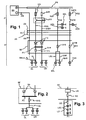
- Fig. 1 shows a schematic representation of excerpts line guides with further appropriate explanation of the invention appropriate elements of a lighting arrangement of a tractor-trailer combination.
- a zugterrorism personer section Z and a trailer-side section A of the schematic structure of the lighting arrangement is distinguished.
- the two sections are electrically connected via a multipolar connector SV with a karGHz section ZS and a trailer-side connector part AS.
- the arrangement is electrically supplied from the DC on-board electrical system BN of the tractor, the negative pole typically forms the electrical vehicle ground as a reference potential and its positive pole is connected in Fig. 1 with a potential distribution rail PS, from which depart the individual circuits.
- the towing vehicle mass ZM is common to all circuits as a reference potential.
- the electric trailer mass AM is contacted by the plug connection SV through with the electrical ground ZM of the towing vehicle, in addition, but also typically exist on metallic mechanical connections between towing vehicle and trailer electrical ground connections between towing vehicle and trailer.
- the lighting functions brake light, turn signals left, turn signals right, reversing lights, rear fog light and taillight group are distinguished as independent functions, in given systems, the taillight group is divided into two independent and separately hedged circuits with a left taillight group GL and a right taillight group GR, which in addition to the actual taillights RL still separate vehicle sides separated outline lights UL, Lane Keeping Lights SL and side marker lights SM.
- a license plate light can be assigned to one of the two tail light groups or, when divided into two lighting parts, two tail light groups.
- the two taillight groups are supplied separately via lines, which are typically distinguished by terminal designations 58L and 58R, and are separately protected in a towing vehicle-side second fuse arrangement SI2 with separate fuses S2L or S2R. Both taillight groups are switched simultaneously via a double switch NG in the towing vehicle.
- the circuits with the terminal designations 58L and 58R only feed the tail light groups GL and GR of the trailer lighting.
- the fuses in the trailer-side first fuse arrangement SI1 are advantageously designed as self-resetting overcurrent fuse elements.
- these fuse elements can act as current limiters which are low-resistance up to a depending on the circuit differently predetermined An Anlagenstromschwelle and limit the current threshold through the fuse element from the An Anlagenstromschwelle to a limiting current which is approximately equal to the An Maschinenschwellstrom.
- the current flowing in the trailer circuits current is limited in the event of a short circuit to the limiting current of the fuse element. Due to the high-impedance fuse element in the event of a short circuit, the power loss predominantly occurs in the short-circuit element itself, in which provision can be made for controlled dissipation of the heat loss, so that even in the event of a short circuit no uncontrolled heat generation is to be expected at any other point in the circuit.
- the current-limiting fuse element remains in the event of malfunction, especially in case of a short circuit without destruction and limits the current through the affected circuit. After elimination of the disturbance, the current-limiting fuse element reverts to the low-resistance state.
- a non-destructive, self-resetting safety element on the trailer side takes into account that often faults occur in the truck trailer area only for a short time, for example, damage to one of the several lighting arrangements by driving on an obstacle, which is often unnoticed by the driver, or by Salt water power bridges, etc., but that after the elimination of such temporary overcurrent situations in the circuit by the use of self-resettable fuse element of the circuit, possibly with the exception of a destroyed or teilzerstörten luminaire arrangement works again and thus over the conventional use of fuses, in which the affected circuit is permanently interrupted until replacement of the fuse, a higher traffic safety is achieved.
- the fuse elements in the first fuse arrangement SI1 on the trailer side are designed as PTC switching fuses, in particular based on polymer (PPTC), which suddenly change into a very high-resistance state when a threshold current is reached by heating a polymer.
- PPTC polymer
- the current in the tripped state of the fuse element is advantageously very low, since the resistance of the fuse element jumps when triggered in the Megaohm Siemens. It thus falls for this circuit in case of failure virtually no power loss.
- PTC switch fuses with the use of series circuits of light-emitting diodes as light sources in the connected trailer-side lighting arrangements.
- circuits of towing vehicle-trailer combination of the circuit for the right turn signal is most easily shown with a zugterrorism solutionen fuse S2FR in the second fuse arrangement SI2, a turn signal switch NFR, a zug mecanical disordering light FZR, a trailer-side self-resetting fuse S1 FR in the first fuse arrangement SI1 and a trailer-side right brake light FAR.
- Fig. 1 also brake light circuit with zugterrorism spiriter safety S2B, brake light switch NB and trailer self-resetting fuse S1B right and left side brake lights BZR and BZL and trailer side right and left side brake lights BAR or BAL are provided on towing vehicle side.
- On the trailer side of the fuse S1 B insofar as a special feature of the wiring is provided to the side brake lights, as two separate longitudinal lines LBL and LBR are provided, which are again cross-interconnected before the brake lights. Due to the cross-connection, a closed conductor loop is formed, so that when severing one of the two longitudinal lines, for example, by an accident, both brake lights BAL and BAR are still functional, resulting in greater road safety leads.
- a special wiring of separate on towing vehicle side and also separately secured lines to the taillights GL and GR provides according to the invention that the separated from the towing vehicle to the connector SV guided lines 58L and 58R on the trailer side after the plug connection to a common potential, represented by the connector PV in Fig. 1, merged and the two taillights groups GL and GR are fed from this common potential. Due to the always common circuit of the two circuits by the light switch group NG, which at the same time also switches the lighting of the towing vehicle with other contacts, there is usually no functional change for the operation of the taillights GL and GR.
- a significant advantage of the potential reunification is that in case of a disturbance in Switzerlandmiliar section of the wiring, for example, response of the fuses S2L or S2R or resistance increase in one of the leads by reducing the cross section of moving kinks, contact problems, etc., the power supply both taillights easily the other intact supply line on towing vehicle side can be taken over.
- the potential combination according to the invention is particularly advantageous in connection with the use of LEDs as lamps in the taillights GL and GR, since thereby the operating current of the taillights for the same light output compared to the use of incandescent lamps can be significantly reduced in conventional lights and also the cumulative operating current through both Tail light groups can be easily carried by only one of the zugizidovs leads and fuses.
- return current barriers are inserted into both line paths 58L, 58R on the trailer side prior to the potential combination in the connector PV, so that when a line path is separated on the towing vehicle side, it is ensured that there is no voltage feedback via the other line path and can be done via the potential merger in the separated part of the interrupted line path.
- the backflow locks can advantageously be designed as semiconductor diodes TD.
- the undisturbed continuation of the operation of both taillight groups even when disturbed in one of the zughusen line routes 58L or 58R contributes in a particularly simple manner significantly to increase road safety by lower probability of failure of parts of the lighting assembly of the trailer.
- no intervention in the line system of commercial vehicles is required, so that the new trailer-side arrangement can be easily operated with all standardized commercial vehicles.
- a variant for the trailer-side circuits of the taillights GL and GR is outlined.
- this variant after the potential combination in the connector PV, only one connecting line VG leads to the rear of the vehicle via a single securing element S1G in the first securing arrangement and branches there to the individual luminaires of the two taillights groups GL and GR.
- a luminaire structure of a lamp LD is schematically outlined with a series connection of a plurality of light-emitting diodes LED.
- the series connection of the light emitting diodes is advantageously provided in or in the housing of the lamp assembly LD an element QD for adjusting the operating current of the series-connected LEDs.
- the element QD can be the simplest Case be a series resistor.
- the element QD may also be a current source, which also serves as a current limiter with varying voltages at the input of the luminaire arrangement.
- the use of a voltage regulator VR is provided for the circuit as a further measure, which is advantageously arranged in front of the self-resetting fuse element SD of the first fuse arrangement SI1.
- the voltage for the lighting circuit can be reduced, for example, to approximately 12 V compared with the value of 24 V typical for on-board networks of tractors.
Abstract
Description
Die Erfindung betrifft eine Anhänger-Beleuchtungsanordnung für eine Zugfahrzeug-Anhänger-Kombination.The invention relates to a trailer lighting arrangement for a tractor-trailer combination.
Bei Zugfahrzeug-Anhänger-Kombinationen werden typischerweise die anhängerseitigen Verbraucher einer Beleuchtungsanordnung über eine mehrpolige Steckerverbindung aus dem Bordnetz des Zugfahrzeugs versorgt. Dabei sind verschiedene Leuchtenstromkreise des Anhängers entsprechend unterschiedlichen Beleuchtungsfunktionen getrennten Polen der Steckerverbindung bzw. getrennten Adern eines Steckerkabels zugeordnet und einzeln im Zugfahrzeug abgesichert. Es ist ferner bekannt, zusätzlich auf Anhängerseite in einer bei der Steckerverbindung frontseitig angeordneten Steuereinrichtung die einzelnen anhängerseitigen Stromkreise nochmals mit separaten Schmelzsicherungen abzusichern.In tractor-trailer combinations typically the trailer-side consumers of a lighting arrangement are supplied via a multi-pin plug connection from the electrical system of the towing vehicle. Different lighting circuits of the trailer are assigned according to different lighting functions separate poles of the plug connection or separate wires of a plug cable and secured individually in the towing vehicle. It is also known, in addition to hedge the individual trailer-side circuits with separate fuses on the trailer side in a front side at the connector control device arranged.
Aus der DE 102 47 307 B3 ist ein Fahrzeugbordnetz mit einer Sicherungsanordnung bekannt, bei welcher höhere Ströme durch Parallelbetrieb von wenigstens zwei Sicherungen an einem Verbraucherstromkreis abgesichert werden können. Neben den bevorzugten Schmelzsicherungen sind auch PTC-Sicherungselemente für den Kfz-Einsatz, z B. aus der DE 202 19 088 U1 an sich bekannt, aber nicht üblich.From DE 102 47 307 B3 a vehicle electrical system with a fuse arrangement is known in which higher currents can be secured by parallel operation of at least two fuses on a load circuit. In addition to the preferred fuses PTC fuse elements for automotive use, for example, from DE 202 19 088 U1 are known per se, but not common.
Die verschiedenen Beleuchtungsfunktionen können insbesondere gegeben sein durch Blinker links, Blinker rechts, Bremslichter, Rückfahrscheinwerfer, Nebelschlussleuchte und/oder die Gruppe mit Rücklichtern, Umriss-, Markierungs-, Spurhalte- und Kennzeichenleuchten, wobei die Lichter der letztgenannten Gruppe immer gemeinsam betrieben sind und typischerweise in Teilgruppen links und rechts über getrennte Adern und Steckerpole versorgt sind und im Zugfahrzeug jeweils separat abgesichert sind. Die Leuchten der anderen Beleuchtungsfunktionen sind typischerweise zusammen mit den funktionsgleichen Leuchten des Zugfahrzeugs abgesichert.The various lighting functions can be given in particular by turn signals on the left, turn signals on the right, brake lights, reversing lights, rear fog lamp and / or the group with taillights, outline, marker, lane keeping and license plate lights, the lights of the latter group are always operated together, and typically in subgroups left and right are supplied via separate wires and plug poles and are separately secured in the towing vehicle. The lights of the other lighting functions are typically secured together with the functionally identical lights of the towing vehicle.
Die Beleuchtungsanordnung unterliegt in den rauhen Bedingungen der Einsatzumgebung einer Vielzahl von Störeinflüssen, welche auch die Absicherung der einzelnen Stromkreise gegen Überströme beeinflussen, wobei unter Sicherheitsaspekten einerseits Beleuchtungsausfälle durch Störungen möglichst gering gehalten werden und andererseits Störungen möglichst zuverlässig und frühzeitig erkannt werden sollen.The lighting arrangement is subject in the harsh conditions of the environment of use of a variety of interference, which also affect the protection of the individual circuits against overcurrents, security issues on the one hand lighting failures are kept as low as possible by disturbances and on the other hand disturbances should be detected as reliably and early.
Der vorliegenden Erfindung liegt die Aufgabe zugrunde, ohne Einbußen bei der elektrischen Sicherheit Beleuchtungsausfälle anhängerseitiger Verbraucher zu verringern und hierbei insbesondere ohne Eingriffe in die elektrischen Systeme der u. U. häufig wechselnden Zugfahrzeuge auszukommen und die Kompatibilität mit bestehenden standardisierten Zugfahrzeug-Versorgungssystemen für die Anhänger-Beleuchtungsanordnung zu wahren.The present invention has for its object to reduce without loss of electrical safety lighting failures trailer-side consumers and this particular without interference with the electrical systems of the u. U. frequently changing towing vehicles and to maintain compatibility with existing standardized tractor supply systems for the trailer lighting arrangement.
Die Erfindung ist im Patentanspruch 1 beschrieben. Die abhängigen Ansprüche enthalten vorteilhafte Ausgestaltungen und Weiterbildungen der Erfindung.The invention is described in claim 1. The dependent claims contain advantageous refinements and developments of the invention.
Die erfindungsgemäßen Maßnahmen sind bevorzugt gemeinsam realisiert. Die Erfindung ist besonders vorteilhaft in Verbindung mit Leuchtenanordnungen, welche mit lichtemittierenden Dioden, insbesondere in Reihenschaltung mehrerer Dioden, ausgestattet sind.The measures according to the invention are preferably realized together. The invention is particularly advantageous in connection with luminaire arrangements which are equipped with light-emitting diodes, in particular in series connection of a plurality of diodes.
Die Zusammenführung von in standardisierten elektrischen Zugfahrzeug-Versorgungssystemen für Anhänger-Beleuchtungsanordnungen getrennten Versorgungsleitungen für linksseitige und rechtsseitige Teilgruppen von Leuchten aus der Gruppe mit Rücklichtern, Umrissleuchten, seitlichen Markierungsleuchten, Spurhalteleuchten und Kennzeichenleuchten auf ein gemeinsames Zwischenpotential auf Anhängerseite verringert die Auswirkungen von zugfahrzeugseitigen Störungen, welche zum Auslösen einer der beiden für die Teilgruppen parallel vorgesehenen Sicherungen führen oder Schäden in einer der beiden parallelen Adern bewirken, auf die anhängerseitige Beleuchtungsanordnung, da der Strom für beide Teilgruppen problemlos auch von nur einem der beiden parallelen zugfahrzeugseitigen Leitungswege getragen werden kann. Besonders vorteilhaft ist hierbei die Verwendung von Leuchtdioden als Leuchtmittel in den angeschlossenen anhängerseitigen Leuchten, da hierdurch der Betriebsstrom deutlich abgesenkt werden kann. Zur Vermeidung von Rückwirkungen eines intakten zugfahrzeugseitigen Leitungswegs auf den durch Auslösen der zugeordneten Sicherung unterbrochenen parallelen Leitungsweg über die Potentialzusammenführung sind anhängerseitig zwischen der Steckerverbindung und der Potentialzusammenführung Rückstromsperren, vorteilhafterweise Halbleiterdioden eingefügt.The merging of separate in standard electric towing vehicle supply systems for trailer lighting arrangements Supply lines for left-sided and right-sided sub-groups of lights from the group comprising taillights, clearance lights, side marker lights, lane lights and license plate lights to a common intermediate potential on the trailer side reduces the effects of vehicle-side interference, which leads to the triggering of one of the two fuses provided in parallel for the subgroups or damage cause in one of the two parallel wires on the trailer side lighting arrangement, since the power for both subgroups can be easily carried by only one of the two parallel zugfahrzeugseitigen cable routes. Particularly advantageous in this case is the use of light-emitting diodes as lighting means in the connected trailer-side luminaires, since in this way the operating current can be significantly reduced. To avoid repercussions of an intact zugfahrzeugseitigen line path on the interrupted by triggering the associated fuse parallel line path on the potential merger trailers between the plug connection and the potential combination return current barriers, advantageously inserted semiconductor diodes.
Besonders vorteilhaft ist der Einsatz von selbstrückstellenden Überstrom-Sicherungselementen in einer anhängerseitigen ersten Sicherungsanordnung zur Überstromsicherung von Stromkreisen der anhängerseitigen Beleuchtungsanordnung, wobei die Ansprechstromquelle dieser selbstrückstellenden Überstrom-Sicherungselemente vorteilhafterweise deutlich unter der Ansprechstromschwelle der zum selben Stromkreis gehörenden Sicherung in der zugfahrzeugseitigen zweiten Sicherungsanordnung liegt. Hierdurch kann die anhängerseitige Sicherung schneller und besser angepasst auf anhängerseitige Störungen reagieren, wodurch die elektrische Sicherheit verbessert wird. Insbesondere aber kann nach Wegfall einer das Ansprechen des Sicherungselements verursachenden Störung das Sicherungselement wieder selbsttätig in den niederohmigen Zustand zurückfallen und somit die Ausfallzeit der betroffenen Beleuchtungsfunktion im wesentlichen auf die Zeit des Vorliegens des störungsbedingten Überstroms bzw. Kurzschlusses beschränkt werden.Particularly advantageous is the use of self-resetting overcurrent fuse elements in a trailer side first fuse arrangement for overcurrent protection of circuits of the trailer side lighting arrangement, the Ansprechstromquelle this self-resetting overcurrent protection elements advantageously well below the Ansprechstromschwelle belonging to the same circuit backup in the zugfahrzeugseitigen second fuse arrangement. As a result, the trailer side fuse faster and better adapted to respond to trailer side disturbances, whereby the electrical safety is improved. In particular, however, after the elimination of a fault causing the response of the fuse element, the fuse element can again be activated automatically fall back the low-impedance state and thus the downtime of the affected lighting function are essentially limited to the time of the presence of the interference-induced overcurrent or short circuit.
In einer ersten vorteilhaften Ausführungsform sind die selbstrückstellenden Überstrom-Sicherungselemente als strombegrenzende Bauteile bzw. Schaltungen ausgeführt. Der Grenzstrom kann dabei vorteilhafterweise auf maximal das 3-fache, insbesondere maximal das 2-fache des Nennstroms des angeschlossenen Leuchten-Stromkreises eingestellt sein. Bei Ansprechen des Sicherungselements fließt nur der Grenzstrom.In a first advantageous embodiment, the self-resetting overcurrent fuse elements are designed as current-limiting components or circuits. The limiting current can advantageously be set to a maximum of 3 times, in particular maximally 2 times, the rated current of the connected lighting circuit. When the fuse element responds only the limiting current flows.
In anderer vorteilhafter Ausführungsform sind als Überstrom-Sicherungselemente PTC-, insbesondere Polymer-PTC-Sicherungen eingesetzt, welche bei einem Strom über der Ansprechschwelle durch Erwärmung in einen hochohmigen Zustand springen und nach Abkühlung wieder niederohmig werden. Von besonderem Vorteil ist hierbei wiederum die Verwendung von Leuchtdioden, vorzugsweise Reihenschaltungen von Leuchtdioden als Leuchtmittel in den angeschlossenen Leuchtenanordnungen, da dann beim Abkühlen des durch den Überstrom erhitzten hochohmigen Sicherungselements der bei Sinken der Temperatur und des Widerstands des Sicherungselements wieder einsetzende Strom bereits bei niedrigen Stromwerten einen großen Spannungsabfall in den Dioden hervorruft und nur wenig Spannung am Sicherungselement abfällt, so dass dieses zuverlässig und schnell weiter abkühlen kann.In another advantageous embodiment are used as overcurrent fuse elements PTC, in particular polymer PTC fuses, which jump at a current above the threshold by heating in a high-resistance state and become low again after cooling. Of particular advantage here again is the use of light emitting diodes, preferably series circuits of light emitting diodes as lighting in the connected lighting arrangements, since then at cooling of the heated by the overcurrent high-resistance fuse element of the sinking of the temperature and the resistance of the fuse element re-starting current even at low current values causes a large voltage drop in the diodes and only little voltage drops on the fuse element, so that it can reliably and quickly cool further.
Das Ansprechen des Sicherungselements kann in vorteilhafter Ausführung ein Störsignal auslösen, welches z. B. bei der ersten Sicherungsanordnung eine optische Anzeige, insbesondere eine Leuchtdiode ansteuern und damit für den Benutzer leicht erkennbar das Vorliegen einer Störung signalisieren kann. Ein Störsignal kann z B. einfach aus einem erhöhten Spannungsabfall am Sicherungselement abgeleitet werden. Vorteilhafterweise ist zu jedem Sicherungselement der ersten Sicherungsanordnung bzw. zu jedem Anhängerstromkreis eine eigene Anzeige vorgesehen. In vorteilhafter Weiterbildung kann vorgesehen sein, dass das Störsignal monostabil geschaltet ist und nach Wegfall einer Störung bestehen bleibt, bis es durch den Benutzer gezielt zurückgesetzt wird oder durch Entfernen der elektrischen Leistungsversorgung, z. B. durch Lösen der Steckerverbindung, gelöscht wird. Durch die monostabile Schaltung des Störsignals kann dem Benutzer auch nach Wegfall der auslösenden Störung angezeigt werden, dass eine Störung vorgelegen hat und der Stromkreis vorsorglich überprüft werden sollte. Das Störsignal kann auch zum Zugfahrzeug übertragen werden, vorzugsweise über eine drahtlose Signalverbindung, und dort dem Fahrer optisch oder akustisch angezeigt werden.The response of the fuse element can trigger an interference signal in an advantageous embodiment, which z. B. in the first fuse arrangement, a visual display, in particular a light emitting diode and thus easily recognizable for the user can signal the presence of a fault. An interference signal can, for example, simply result from an increased voltage drop across the fuse element be derived. Advantageously, a separate display is provided for each fuse element of the first fuse arrangement or for each trailer circuit. In an advantageous embodiment, it can be provided that the interference signal is switched monostable and remains after elimination of a fault until it is selectively reset by the user or by removing the electrical power supply, for. B. by loosening the plug connection is deleted. Due to the monostable circuit of the interference signal, the user can be displayed even after elimination of the triggering fault that a fault has been present and the circuit should be checked as a precaution. The interference signal can also be transmitted to the towing vehicle, preferably via a wireless signal connection, where it is visually or acoustically displayed to the driver.
Zusätzlich zu den Sicherungselementen der ersten Sicherungsanordnung können noch selbstrückstellende Sicherungselemente bei den einzelnen Leuchtenanordnungen vorgesehen sein, welche wiederum eine niedrigere Ansprechschwelle aufweisen können als das dem Anhängerstromkreis zugeordnete Sicherungselement in der ersten Sicherungsanordnung.In addition to the fuse elements of the first fuse arrangement, self-resetting fuse elements can still be provided in the individual lamp arrangements, which in turn may have a lower threshold than the fuse element associated with the trailer circuit in the first fuse arrangement.
Die Erfindung ist nachfolgend anhand bevorzugter Ausführungsbeispiele unter Bezugnahme auf die Abbildungen noch eingehend veranschaulicht. Dabei zeigt:
- Fig. 1
- schematische Stromkreisabschnitte einer Beleuchtungsanordnung einer Zugfahrzeug-Anhänger-Kombination,
- Fig. 2
- eine alternative Ausführung eines anhängerseitigen Stromkreises,
- Fig. 3
- eine Leuchtenanordnung in einem anhängerseitigen Stromkreis.
- Fig. 1
- schematic circuit sections of a lighting arrangement of a tractor-trailer combination,
- Fig. 2
- an alternative embodiment of a trailer-side circuit,
- Fig. 3
- a luminaire arrangement in a trailer-side circuit.
Fig. 1 zeigt in schematischer Darstellung auszugsweise Leitungsführungen mit zur weiteren Erläuterung der Erfindung zweckmäßigen Elementen einer Beleuchtungsanordnung einer Zugfahrzeug-Anhänger-Kombination. In der Zeichnung ist ein zugfahrzeugseitiger Abschnitt Z und ein anhängerseitiger Abschnitt A des schematischen Aufbaus der Beleuchtungsanordnung unterschieden. Die beiden Abschnitte sind über eine mehrpolige Steckerverbindung SV mit einem zugfahrzeugseitigen Steckerteil ZS und einem anhängerseitigen Steckerteil AS elektrisch verbunden.Fig. 1 shows a schematic representation of excerpts line guides with further appropriate explanation of the invention appropriate elements of a lighting arrangement of a tractor-trailer combination. In the drawing, a zugfahrzeugseitiger section Z and a trailer-side section A of the schematic structure of the lighting arrangement is distinguished. The two sections are electrically connected via a multipolar connector SV with a zugfahrzeugseitigen connector part ZS and a trailer-side connector part AS.
Die Anordnung ist elektrisch versorgt aus dem Gleichstrom-Bordnetz BN des Zugfahrzeugs, dessen Minuspol typischerweise als Referenzpotential die elektrische Fahrzeugmasse bildet und dessen Pluspol in Fig. 1 mit einer Potentialverteilerschiene PS verbunden ist, von welcher aus die einzelnen Stromkreise abgehen. Die Zugfahrzeugmasse ZM ist allen Stromkreisen als Referenzpotential gemeinsam. Die elektrische Anhängermasse AM ist zum einen durch die Steckerverbindung SV hindurch mit der elektrischen Masse ZM des Zugfahrzeugs kontaktiert, darüber hinaus bestehen aber auch typischerweise über metallische mechanische Verbindungen zwischen Zugfahrzeug und Anhänger noch elektrische Masseverbindungen zwischen Zugfahrzeug und Anhänger.The arrangement is electrically supplied from the DC on-board electrical system BN of the tractor, the negative pole typically forms the electrical vehicle ground as a reference potential and its positive pole is connected in Fig. 1 with a potential distribution rail PS, from which depart the individual circuits. The towing vehicle mass ZM is common to all circuits as a reference potential. The electric trailer mass AM is contacted by the plug connection SV through with the electrical ground ZM of the towing vehicle, in addition, but also typically exist on metallic mechanical connections between towing vehicle and trailer electrical ground connections between towing vehicle and trailer.
Auf Anhängerseite werden innerhalb der Beleuchtungsanordnung des Anhängers typischerweise die Beleuchtungsfunktionen Bremslicht, Blinker links, Blinker rechts, Rückfahrscheinwerfer, Nebelschlussleuchte und Rücklichtgruppe als unabhängige Funktionen unterschieden, wobei in gegebenen Systemen die Rücklichtgruppe aufgeteilt ist in zwei unabhängige und separat abgesicherte Stromkreise mit einer linken Rücklichtgruppe GL und einer rechten Rücklichtgruppe GR, welche jeweils neben den eigentlichen Rücklichtern RL noch nach Fahrzeugseiten getrennt Umrissleuchten UL, Spurhalteleuchten SL und seitliche Markierungsleuchten SM umfassen. Eine Kennzeichenbeleuchtung kann einer der beiden Rücklichtgruppen oder bei Aufteilung in zwei Beleuchtungsteile beiden Rücklichtgruppen zugeordnet sein. Die beiden Rücklichtgruppen sind über Leitungen, welche typischerweise mit Klemmenbezeichnungen 58L und 58R unterschieden sind, separat versorgt und in einer zugfahrzeugseitigen zweiten Sicherungsanordnung SI2 auch mit separaten Sicherungen S2L bzw. S2R getrennt abgesichert. Beide Rücklichtgruppen werden aber simultan über einen Doppelschalter NG im Zugfahrzeug geschaltet. Über die Stromkreise mit den Klemmenbezeichnungen 58L und 58R werden lediglich die Rücklichtgruppen GL und GR der Anhängerbeleuchtung gespeist.On the trailer side within the lighting arrangement of the trailer typically the lighting functions brake light, turn signals left, turn signals right, reversing lights, rear fog light and taillight group are distinguished as independent functions, in given systems, the taillight group is divided into two independent and separately hedged circuits with a left taillight group GL and a right taillight group GR, which in addition to the actual taillights RL still separate vehicle sides separated outline lights UL, Lane Keeping Lights SL and side marker lights SM. A license plate light can be assigned to one of the two tail light groups or, when divided into two lighting parts, two tail light groups. The two taillight groups are supplied separately via lines, which are typically distinguished by terminal designations 58L and 58R, and are separately protected in a towing vehicle-side second fuse arrangement SI2 with separate fuses S2L or S2R. Both taillight groups are switched simultaneously via a double switch NG in the towing vehicle. The circuits with the terminal designations 58L and 58R only feed the tail light groups GL and GR of the trailer lighting.
Im Unterschied dazu sind bei den übrigen genannten unabhängigen Beleuchtungsfunktionen jeweils nur ein Stromkreis mit einer Sicherung und einem Schalter vorgesehen und die Stromkreise speisen neben den jeweils betroffenen Leuchten der Anhänger-Beleuchtungsanordnung auch die funktional gleichen Leuchten des Zugfahrzeugs. Als Beispiele für solche weiteren Stromkreise sind ein Bremslicht-Stromkreis mit einer zugfahrzeugseitigen Sicherung S2B, zugfahrzeugseitigen beidseitigen Bremsleuchten BZL und BZR sowie anhängerseitigen beidseitigen Bremsleuchten BAL und BAR sowie ein Blinklicht-Stromkreis rechts mit einer eigenen Sicherung S2FR in der zugfahrzeugseitigen Sicherungsanordnung SI2, wenigstens einem rechten Blinklicht FZR am Zugfahrzeug und wenigstens einem rechten Blinklicht FAR am Anhänger in Fig. 1 mit eingezeichnet. Die übrigen Komponenten und Stromkreise der Beleuchtungsanordnung der Zugfahrzeug-Anhänger-Kombination sind der Übersichtlichkeit halber weg gelassen.In contrast, only one circuit with a fuse and a switch are provided in the other mentioned independent lighting functions and the circuits feed next to each affected lights of the trailer lighting arrangement and the functionally same lights of the towing vehicle. As examples of such further circuits are a brake light circuit with a zugfahrzeugseitigen fuse S2B, zugfahrzeugseitigen two-sided brake lights BZL and BZR and trailer side double-sided brake lights BAL and BAR and a flashing light circuit right with its own fuse S2FR in the zugfahrzeugseitigen fuse arrangement SI2, at least one right Flashing light FZR on towing vehicle and at least one right flashing light FAR on the trailer in Fig. 1 with. The remaining components and circuits of the lighting arrangement of towing vehicle-trailer combination are left out for the sake of clarity.
Es ist darüber hinaus bekannt, auf Anhängerseite in einer primär als Verteiler fungierenden frontseitigen Steuereinrichtung SE eine eigene Sicherungsanordnung SI1 vorzusehen. Die Ansprechstromschwellen der Sicherung in der ersten Sicherungsanordnung SI1 auf Anhängerseite können, insbesondere bei den Stromkreisen, welche sowohl anhängerseitige als auch zugfahrzeugseitige Leuchtenanordnungen versorgen, niedriger liegen als in der zweiten Sicherungsanordnung SI2 im Zugfahrzeug. Bei der erfindungsgemäßen Beleuchtungsanordnung sind die Sicherungen in der anhängerseitigen ersten Sicherungsanordnung SI1 vorteilhafterweise als selbstrückstellende Überstrom-Sicherungselemente ausgeführt.It is also known to provide on the trailer side in a primary acting as a distributor front-side control device SE own security arrangement SI1. The Ansprechstromschwellen the fuse in the first fuse arrangement SI1 on the trailer side, especially in the circuits that supply both trailer-side and zugfahrzeugseitige lamp assemblies are lower than in the second fuse assembly SI2 in the towing vehicle. In the lighting arrangement according to the invention, the fuses in the trailer-side first fuse arrangement SI1 are advantageously designed as self-resetting overcurrent fuse elements.
In einer ersten vorteilhaften Ausführungsform können diese Sicherungselemente als Strombegrenzer wirken, welche bis zu einer je nach Stromkreis unterschiedlich vorgegebenen Ansprechstromschwelle niederohmig sind und ab der Ansprechstromschwelle den Strom durch das Sicherungselement auf einen Grenzstrom beschränken, welcher annähernd gleich dem Ansprechschwellstrom ist. Hierdurch wird der in den Anhängerstromkreisen fließende Strom im Kurzschlussfall auf den Grenzstrom des Sicherungselements begrenzt. Durch das im Kurzschlussfall hochohmige Sicherungselement fällt die Verlustleistung überwiegend in dem Kurzschlusselement selbst an, bei welchem für eine kontrollierte Abführung der Verlustwärme vorgesorgt werden kann, so dass auch im Kurzschlussfall keine unkontrollierte Hitzeentwicklung an irgend einer anderen Stelle im Stromkreis zu erwarten ist.In a first advantageous embodiment, these fuse elements can act as current limiters which are low-resistance up to a depending on the circuit differently predetermined Ansprechstromschwelle and limit the current threshold through the fuse element from the Ansprechstromschwelle to a limiting current which is approximately equal to the Ansprechschwellstrom. As a result, the current flowing in the trailer circuits current is limited in the event of a short circuit to the limiting current of the fuse element. Due to the high-impedance fuse element in the event of a short circuit, the power loss predominantly occurs in the short-circuit element itself, in which provision can be made for controlled dissipation of the heat loss, so that even in the event of a short circuit no uncontrolled heat generation is to be expected at any other point in the circuit.
Das strombegrenzende Sicherungselement bleibt im Störungsfall, insbesondere auch im Kurzschlussfall zerstörungsfrei erhalten und begrenzt den Strom durch den betroffenen Stromkreis. Nach Wegfall der Störung geht das strombegrenzende Sicherungselement wieder in den niederohmigen Zustand über.The current-limiting fuse element remains in the event of malfunction, especially in case of a short circuit without destruction and limits the current through the affected circuit. After elimination of the disturbance, the current-limiting fuse element reverts to the low-resistance state.
Der Einsatz eines zerstörungsfrei reagierenden, selbstrückstellenden Sicherungselements auf Anhängerseite trägt der Erkenntnis Rechnung, dass häufig Störungen im Lastfahrzeug-Anhängerbereich nur kurzfristig auftreten, beispielsweise bei Beschädigung einer der mehreren Leuchtenanordnungen durch Auffahren auf ein Hindernis, was häufig auch vom Fahrer nicht bemerkt wird, oder durch Salzwasser-Strombrücken usw., dass aber nach Wegfall solcher temporärer Überstrom-Situationen im Stromkreis durch den Einsatz des selbstrückstellenden Sicherungselement der Stromkreis, gegebenenfalls mit Ausnahme einer zerstörten oder teilzerstörten Leuchtenanordnung wieder funktioniert und damit gegenüber dem gebräuchlichen Einsatz von Schmelzsicherungen, bei welchen der betroffene Stromkreis bis zum Auswechseln der Schmelzsicherung dauerhaft unterbrochen ist, eine höhere Verkehrssicherheit erreicht wird.The use of a non-destructive, self-resetting safety element on the trailer side takes into account that often faults occur in the truck trailer area only for a short time, for example, damage to one of the several lighting arrangements by driving on an obstacle, which is often unnoticed by the driver, or by Salt water power bridges, etc., but that after the elimination of such temporary overcurrent situations in the circuit by the use of self-resettable fuse element of the circuit, possibly with the exception of a destroyed or teilzerstörten luminaire arrangement works again and thus over the conventional use of fuses, in which the affected circuit is permanently interrupted until replacement of the fuse, a higher traffic safety is achieved.
In anderer vorteilhafter Ausführungsform sind die Sicherungselemente in der ersten Sicherungsanordnung SI1 auf Anhängerseite als PTC-Schaltsicherungen, insbesondere auf Polymerbasis (PPTC) ausgeführt, welche ab Erreichen einer Ansprechstromschwelle durch Erwärmung eines Polymers sprunghaft in einen sehr hochohmigen Zustand übergehen. Durch Abkühlen des Polymers, beispielsweise nach Wegfall eines temporären Kurzschlusses im Stromkreis oder nach Lösen der Steckerverbindung SV, gehen derartige PTC-Schaltsicherungen wieder in den niederohmigen Zustand über. Bei derartigen PTC-Schaltsicherungen ist der Strom im ausgelösten Zustand des Sicherungselements vorteilhafterweise sehr gering, da der Widerstand des Sicherungselements beim Auslösen in den Megaohmbereich springt. Es fällt damit für diesen Stromkreis im Störungsfall praktisch keine Verlustleistung an. Besonders vorteilhaft ist die Kombination solcher PTC-Schaltsicherungen mit der Verwendung von Reihenschaltungen von Leuchtdioden als Leuchtmitteln in den angeschlossenen anhängerseitigen Leuchtenanordnungen. Der beim Abkühlen des ausgelösten Sicherungselements nach Wegfall beispielsweise eines Kurzschlusses allmählich wieder einsetzende Strom durch das Sicherungselement führt bereits bei sehr geringen Stromstärken in der Leuchtenanordnung zu einem relativ hohen Spannungsabfall entsprechend der Summe der Durchlassspannungen der Leuchtdioden-Reihenschaltung, so dass am Sicherungselement selbst nur noch ein geringer Spannungsabfall und damit auch nur noch eine geringe Verlustleistung anfällt und die Abkühlung des Sicherungselements schnell erfolgen kann.In another advantageous embodiment, the fuse elements in the first fuse arrangement SI1 on the trailer side are designed as PTC switching fuses, in particular based on polymer (PPTC), which suddenly change into a very high-resistance state when a threshold current is reached by heating a polymer. By cooling the polymer, for example, after elimination of a temporary short circuit in the circuit or after loosening the connector SV, go such PTC switching fuses again in the low-resistance state. In such PTC switch fuses the current in the tripped state of the fuse element is advantageously very low, since the resistance of the fuse element jumps when triggered in the Megaohmbereich. It thus falls for this circuit in case of failure virtually no power loss. Particularly advantageous is the combination of such PTC switch fuses with the use of series circuits of light-emitting diodes as light sources in the connected trailer-side lighting arrangements. The while cooling the triggered fuse element after elimination, for example, a short circuit gradually re-entering current through the fuse element leads at very low currents in the lamp assembly to a relatively high voltage drop corresponding to the sum of the forward voltages of the light-emitting diode series, so that the fuse element itself only a small voltage drop and thus Even only a small power loss is incurred and the cooling of the fuse element can be done quickly.
Bei den in Fig. 1 dargestellten Stromkreisen der Zugfahrzeug-Anhänger-Kombination ist der Stromkreis für den rechten Blinker am einfachsten aufgebaut dargestellt mit einer zugfahrzeugseitigen Schmelzsicherung S2FR in der zweiten Sicherungsanordnung SI2, einem Blinkerschalter NFR, einer zugfahrzeugseitigen Blinkleuchte FZR, einer anhängerseitigen selbstrückstellenden Sicherung S1 FR in der ersten Sicherungsanordnung SI1 und einer anhängerseitigen rechten Bremsleuchte FAR.In the illustrated in Fig. 1 circuits of towing vehicle-trailer combination of the circuit for the right turn signal is most easily shown with a zugfahrzeugseitigen fuse S2FR in the second fuse arrangement SI2, a turn signal switch NFR, a zugfahrzeugseitigen flashing light FZR, a trailer-side self-resetting fuse S1 FR in the first fuse arrangement SI1 and a trailer-side right brake light FAR.
Bei dem in Fig. 1 gleichfalls dargestellten Bremslichtschaltkreis mit zugfahrzeugseitiger Schmelzsicherung S2B, Bremslichtschalter NB und anhängerseitiger selbstrückstellender Sicherung S1B sind auf Zugfahrzeugseite rechts- und linksseitige Bremsleuchten BZR und BZL und auf Anhängerseite rechtsseitige und linksseitige Bremsleuchten BAR bzw. BAL vorgesehen. Auf Anhängerseite ist nach der Sicherung S1 B insoweit eine Besonderheit der Leitungsführung zu den seitlichen Bremsleuchten vorgesehen, als zwei separate Längsleitungen LBL und LBR vorgesehen sind, welche vor den Bremsleuchten wieder untereinander querverbunden sind. Durch die Querverbindung wird eine geschlossene Leiterschleife gebildet, so dass bei Durchtrennung einer der beiden Längsleitungen, beispielsweise durch einen Unfall, dennoch beide Bremsleuchten BAL und BAR funktionsfähig sind, was zu höherer Verkehrssicherheit führt. Eine besondere Beschaltung der auf Zugfahrzeugseite getrennten und auch getrennt abgesicherten Leitungen zu den Rücklichtgruppen GL und GR sieht gemäß der Erfindung vor, dass die vom Zugfahrzeug getrennt zu der Steckerverbindung SV geführten Leitungen 58L und 58R auf Anhängerseite nach der Steckerverbindung auf ein gemeinsames Potential, repräsentiert durch den Verbinder PV in Fig. 1, zusammengeführt werden und die beiden Rücklichtgruppen GL und GR aus diesem gemeinsamen Potential gespeist werden. Durch die immer gemeinsame Schaltung der beiden Stromkreise durch die Lichtschaltergruppe NG, welche typischerweise mit weiteren Kontakten gleichzeitig auch die Beleuchtung des Zugfahrzeugs schaltet, ergibt sich im Regelfall keine funktionale Änderung für den Betrieb der Rücklichtgruppen GL und GR. Ein wesentlicher Vorteil der Potentialzusammenführung besteht aber darin, dass bei einer Störung im zugfahrzeugseitigen Teil der Leitungsführung, beispielsweise Ansprechen einer der Schmelzsicherungen S2L oder S2R oder durch Widerstandsanstieg in einer der Zuleitungen durch Querschnittsverringerung an bewegten Knickstellen, durch Kontaktprobleme usw. die Leistungsversorgung beider Rücklichtgruppen problemlos durch die andere intakte Zuleitung auf Zugfahrzeugseite mit übernommen werden kann. Die erfindungsgemäße Potentialzusammenführung ist besonders vorteilhaft in Verbindung mit der Verwendung von Leuchtdioden als Leuchtmitteln in den Rücklichtgruppen GL und GR, da dadurch der Betriebsstrom der Rücklichtgruppen für gleiche Lichtleistung gegenüber der Verwendung von Glühlampen in herkömmlichen Leuchten deutlich verringert werden kann und auch der kumulierte Betriebsstrom durch beide Rücklichtgruppen problemlos von nur einer der zugfahrzeugseitigen Zuleitungen und Sicherungen getragen werden kann. Vorteilhafterweise sind vor der Potentialzusammenführung in dem Verbinder PV Rückstromsperren in beide Leitungswege 58L, 58R auf Anhängerseite eingefügt, so dass bei Auftrennung eines Leitungsweges auf der Zugfahrzeugseite sicher gestellt wird, dass keine Spannungsrückführung über den anderen Leitungsweg und über die Potentialzusammenführung in den abgetrennten Teil des unterbrochenen Leitungswegs erfolgen kann. Die Rückstromsperren können vorteilhafterweise als Halbleiterdioden TD ausgeführt sein. Die ungestörte Fortsetzung des Betriebs beider Rücklichtgruppen auch bei Störung in einem der zugfahrzeugseitigen Leitungswege 58L oder 58R trägt auf besonders einfache Weise erheblich zur Erhöhung der Verkehrssicherheit durch geringere Ausfallwahrscheinlichkeit von Teilen der Beleuchtungsanordnung des Anhängers bei. Vorteilhafterweise ist dabei keinerlei Eingriff in das Leitungssystem der Nutzfahrzeuge erforderlich, so dass die neue anhängerseitige Anordnung problemlos mit allen standardisierten Nutzfahrzeugen betrieben werden kann.In the illustrated in Fig. 1 also brake light circuit with zugfahrzeugseitiger safety S2B, brake light switch NB and trailer self-resetting fuse S1B right and left side brake lights BZR and BZL and trailer side right and left side brake lights BAR or BAL are provided on towing vehicle side. On the trailer side of the fuse S1 B insofar as a special feature of the wiring is provided to the side brake lights, as two separate longitudinal lines LBL and LBR are provided, which are again cross-interconnected before the brake lights. Due to the cross-connection, a closed conductor loop is formed, so that when severing one of the two longitudinal lines, for example, by an accident, both brake lights BAL and BAR are still functional, resulting in greater road safety leads. A special wiring of separate on towing vehicle side and also separately secured lines to the taillights GL and GR provides according to the invention that the separated from the towing vehicle to the connector SV guided lines 58L and 58R on the trailer side after the plug connection to a common potential, represented by the connector PV in Fig. 1, merged and the two taillights groups GL and GR are fed from this common potential. Due to the always common circuit of the two circuits by the light switch group NG, which at the same time also switches the lighting of the towing vehicle with other contacts, there is usually no functional change for the operation of the taillights GL and GR. However, a significant advantage of the potential reunification is that in case of a disturbance in Zugfahrzeugseitigen part of the wiring, for example, response of the fuses S2L or S2R or resistance increase in one of the leads by reducing the cross section of moving kinks, contact problems, etc., the power supply both taillights easily the other intact supply line on towing vehicle side can be taken over. The potential combination according to the invention is particularly advantageous in connection with the use of LEDs as lamps in the taillights GL and GR, since thereby the operating current of the taillights for the same light output compared to the use of incandescent lamps can be significantly reduced in conventional lights and also the cumulative operating current through both Tail light groups can be easily carried by only one of the zugfahrzeugseitigen leads and fuses. Advantageously, return current barriers are inserted into both line paths 58L, 58R on the trailer side prior to the potential combination in the connector PV, so that when a line path is separated on the towing vehicle side, it is ensured that there is no voltage feedback via the other line path and can be done via the potential merger in the separated part of the interrupted line path. The backflow locks can advantageously be designed as semiconductor diodes TD. The undisturbed continuation of the operation of both taillight groups even when disturbed in one of the zugfahrzeugseitigen line routes 58L or 58R contributes in a particularly simple manner significantly to increase road safety by lower probability of failure of parts of the lighting assembly of the trailer. Advantageously, no intervention in the line system of commercial vehicles is required, so that the new trailer-side arrangement can be easily operated with all standardized commercial vehicles.
Im skizzierten Beispiel der Fig. 1 führen nach der Potentialzusammenführung im Verbinder PV von dem einheitlichen Potential getrennte Leitungen über separate selbstrückstellende Sicherungen S1 L bzw. S1R der ersten Sicherungsanordnung SI1 zu den Rücklichtgruppen GL und GR, welche jeweils eine Mehrzahl einzelner Leuchten in separaten Gehäusen umfassen.In the sketched example of FIG. 1, after potential bonding in the connector PV separate lines lead from the uniform potential via separate self-resetting fuses S1 L or S1R of the first fuse arrangement SI1 to the backlight groups GL and GR, which each include a plurality of individual lights in separate housings ,
In Fig. 2 ist eine Variante für die anhängerseitigen Stromkreise der Rücklichtgruppen GL und GR skizziert. In dieser Variante führt nach der Potentialzusammenführung in dem Verbinder PV lediglich eine Verbindungsleitung VG über ein einzelnes Sicherungselement S1G in der ersten Sicherungsanordnung zum Fahrzeugheck und verzweigt sich dort auf die einzelnen Leuchten der beiden Rücklichtgruppen GL und GR.In Fig. 2 a variant for the trailer-side circuits of the taillights GL and GR is outlined. In this variant, after the potential combination in the connector PV, only one connecting line VG leads to the rear of the vehicle via a single securing element S1G in the first securing arrangement and branches there to the individual luminaires of the two taillights groups GL and GR.
In Fig. 3 ist schematisch ein Leuchtenaufbau einer Leuchte LD mit einer Reihenschaltung von mehreren Leuchtdioden LED skizziert. Der Reihenschaltung der Leuchtdioden ist im oder beim Gehäuse der Leuchtenanordnung LD vorteilhafterweise ein Element QD zur Einstellung des Betriebsstroms der in Reihe geschalteten Leuchtdioden vorgesehen. Das Element QD kann im einfachsten Fall ein Vorwiderstand sein. In anderer Ausführung kann das Element QD auch eine Stromquelle sein, welche zugleich als Strombegrenzer bei variierenden Spannungen am Eingang der Leuchtenanordnung dient. In der Steuereinrichtung SE ist für den Stromkreis als weitere Maßnahme der Einsatz eines Spannungsreglers VR vorgesehen, welcher vorteilhafterweise vor dem selbstrückstellenden Sicherungselement SD der ersten Sicherungsanordnung SI1 angeordnet ist. Mittels des Spannungsreglers VR kann die Spannung für den Leuchtenstromkreis beispielsweise auf ca. 12 V gegenüber den für Bordnetzen von Zugmaschinen typischen Wert von 24 V herabgesetzt werden.In Fig. 3, a luminaire structure of a lamp LD is schematically outlined with a series connection of a plurality of light-emitting diodes LED. The series connection of the light emitting diodes is advantageously provided in or in the housing of the lamp assembly LD an element QD for adjusting the operating current of the series-connected LEDs. The element QD can be the simplest Case be a series resistor. In another embodiment, the element QD may also be a current source, which also serves as a current limiter with varying voltages at the input of the luminaire arrangement. In the control device SE, the use of a voltage regulator VR is provided for the circuit as a further measure, which is advantageously arranged in front of the self-resetting fuse element SD of the first fuse arrangement SI1. By means of the voltage regulator VR, the voltage for the lighting circuit can be reduced, for example, to approximately 12 V compared with the value of 24 V typical for on-board networks of tractors.
Die vorstehend und die in den Ansprüchen angegebenen sowie die den Abbildungen entnehmbaren Merkmale sind sowohl einzeln als auch in verschiedener Kombination vorteilhaft realisierbar. Die Erfindung ist nicht auf die beschriebenen Ausführungsbeispiele beschränkt, sondern im Rahmen fachmännischen Könnens in mancherlei Weise abwandelbar.The features indicated above and in the claims, as well as the features which can be seen in the figures, can be implemented advantageously both individually and in various combinations. The invention is not limited to the exemplary embodiments described, but can be modified in many ways within the scope of expert knowledge.
Claims (13)
und/oder
and or
Applications Claiming Priority (1)
| Application Number | Priority Date | Filing Date | Title |
|---|---|---|---|
| DE200410036342 DE102004036342A1 (en) | 2004-07-27 | 2004-07-27 | Trailer lighting arrangement for a tractor-trailer combination |
Publications (1)
| Publication Number | Publication Date |
|---|---|
| EP1621401A1 true EP1621401A1 (en) | 2006-02-01 |
Family
ID=35063182
Family Applications (1)
| Application Number | Title | Priority Date | Filing Date |
|---|---|---|---|
| EP05015054A Withdrawn EP1621401A1 (en) | 2004-07-27 | 2005-07-12 | Trailer-indicating arrangement for a tractor-trailer-combination |
Country Status (2)
| Country | Link |
|---|---|
| EP (1) | EP1621401A1 (en) |
| DE (1) | DE102004036342A1 (en) |
Cited By (1)
| Publication number | Priority date | Publication date | Assignee | Title |
|---|---|---|---|---|
| CN114051305A (en) * | 2021-12-02 | 2022-02-15 | 北京福田戴姆勒汽车有限公司 | Trailer tail lamp control device and connection state judgment method |
Citations (8)
| Publication number | Priority date | Publication date | Assignee | Title |
|---|---|---|---|---|
| EP0483650A1 (en) * | 1990-10-27 | 1992-05-06 | Dietrich Gebhard | Circuit arrangement for a towing vehicle |
| WO1992015473A1 (en) * | 1991-03-08 | 1992-09-17 | Kjell Rune Fundin | Electric control means in vehicles |
| DE29515223U1 (en) * | 1995-09-26 | 1995-11-23 | Siemens Ag | Circuit board |
| US6259170B1 (en) * | 1998-06-15 | 2001-07-10 | Draw-Tite, Inc. | Bi-color led trailer connector circuit protector and indicator |
| DE20219088U1 (en) | 2002-01-26 | 2003-05-22 | Ellenberger & Poensgen | Circuit protection against overcurrent, especially for cars with positive temperature coefficient (PTC) element |
| DE10247307B3 (en) | 2002-10-10 | 2004-01-22 | Siemens Ag | Vehicle electrical system |
| DE10236304A1 (en) * | 2002-08-08 | 2004-02-19 | Hella Kg Hueck & Co. | Circuit arrangement for control and monitoring of electrical lighting devices in trailer vehicles, has protective diode connected between load side connection of each power switch and common line |
| DE10236302A1 (en) * | 2002-08-08 | 2004-02-19 | Hella Kg Hueck & Co. | Circuit arrangement for control and monitoring electrical lighting devices in trailer vehicles, feeds voltage signal from each illumination device to microprocessor voltage monitoring input |
Family Cites Families (2)
| Publication number | Priority date | Publication date | Assignee | Title |
|---|---|---|---|---|
| DE4424471C2 (en) * | 1994-07-12 | 1997-03-20 | Daimler Benz Ag | Electrical trailer connection device for a towing vehicle |
| DE20117386U1 (en) * | 2001-10-28 | 2002-01-24 | Aicher Andreas | Circuit for a voltage converter |
-
2004
- 2004-07-27 DE DE200410036342 patent/DE102004036342A1/en not_active Withdrawn
-
2005
- 2005-07-12 EP EP05015054A patent/EP1621401A1/en not_active Withdrawn
Patent Citations (8)
| Publication number | Priority date | Publication date | Assignee | Title |
|---|---|---|---|---|
| EP0483650A1 (en) * | 1990-10-27 | 1992-05-06 | Dietrich Gebhard | Circuit arrangement for a towing vehicle |
| WO1992015473A1 (en) * | 1991-03-08 | 1992-09-17 | Kjell Rune Fundin | Electric control means in vehicles |
| DE29515223U1 (en) * | 1995-09-26 | 1995-11-23 | Siemens Ag | Circuit board |
| US6259170B1 (en) * | 1998-06-15 | 2001-07-10 | Draw-Tite, Inc. | Bi-color led trailer connector circuit protector and indicator |
| DE20219088U1 (en) | 2002-01-26 | 2003-05-22 | Ellenberger & Poensgen | Circuit protection against overcurrent, especially for cars with positive temperature coefficient (PTC) element |
| DE10236304A1 (en) * | 2002-08-08 | 2004-02-19 | Hella Kg Hueck & Co. | Circuit arrangement for control and monitoring of electrical lighting devices in trailer vehicles, has protective diode connected between load side connection of each power switch and common line |
| DE10236302A1 (en) * | 2002-08-08 | 2004-02-19 | Hella Kg Hueck & Co. | Circuit arrangement for control and monitoring electrical lighting devices in trailer vehicles, feeds voltage signal from each illumination device to microprocessor voltage monitoring input |
| DE10247307B3 (en) | 2002-10-10 | 2004-01-22 | Siemens Ag | Vehicle electrical system |
Non-Patent Citations (1)
| Title |
|---|
| STAUDT, WILFRIED; MOOS, DIETER: "Kraftfahrzeugtechnik - Technologie für Automobil- und Kraftfahrzeugmechaniker", 1988, FRIEDR. VIEWEG & SOHN, BRAUNSCHWEIG/WIESBADEN (DE), XP002355667 * |
Cited By (1)
| Publication number | Priority date | Publication date | Assignee | Title |
|---|---|---|---|---|
| CN114051305A (en) * | 2021-12-02 | 2022-02-15 | 北京福田戴姆勒汽车有限公司 | Trailer tail lamp control device and connection state judgment method |
Also Published As
| Publication number | Publication date |
|---|---|
| DE102004036342A1 (en) | 2006-03-16 |
Similar Documents
| Publication | Publication Date | Title |
|---|---|---|
| EP1151639B1 (en) | Control circuit for led and corresponding operating method | |
| DE4010765C1 (en) | ||
| DE102004020691B4 (en) | vehicle light | |
| DE10353064B4 (en) | Vehicle turn signal system and flasher circuit for the same | |
| EP2000359B1 (en) | Switching assembly | |
| DE102006015053A1 (en) | LED turn signals and fault detection method | |
| DE19708659C1 (en) | Flashing light signal system for motor vehicle | |
| EP2000358B1 (en) | Circuit for supplying power to LED in a trailer | |
| EP0279168B1 (en) | Circuit for the power supply of a multitude of consumers | |
| EP1967393B1 (en) | Electric trailer connection device | |
| EP0483650B1 (en) | Circuit arrangement for a towing vehicle | |
| DE3724916A1 (en) | Motor vehicle for use with trailers with monitoring of the rear lights | |
| DE4137611A1 (en) | Direction and hazard light indication system for motor vehicle - has additional input to timing controller and logic integrated circuit to safeguard rate of hazard flashing. | |
| EP1621401A1 (en) | Trailer-indicating arrangement for a tractor-trailer-combination | |
| DE2007702C3 (en) | Electric circuit for the automatic switching on of park lights | |
| EP0129221B1 (en) | Circuit arrangement for a traction vehicle | |
| DE10211099B4 (en) | Device for controlling an electrical load | |
| DE102013001976B3 (en) | Light signal device for vehicle e.g. passenger car, has LEDs which are arranged in region of headlights and rear lights of vehicle, and luminous element which is activated for detecting failure of electrical system of vehicle | |
| DE2700995A1 (en) | Lamp failure warning device - has LED bridged by reed switch in lamp circuit | |
| DE202010016339U1 (en) | circuitry | |
| DE2439533A1 (en) | Fuse system for all components in vehicle - fuse bridging solenoid for starter motor | |
| EP3580096B1 (en) | Headlight for motor vehicles, comprising at least one light source | |
| DE19937491B4 (en) | Safety device for the electrical system of a vehicle | |
| DE2919356A1 (en) | DEVICE FOR MONITORING AND DISPLAYING THE FUNCTIONALITY OF VEHICLE EQUIPMENT | |
| DE1917527A1 (en) | Switching device for flashing light systems in motor vehicles |
Legal Events
| Date | Code | Title | Description |
|---|---|---|---|
| PUAI | Public reference made under article 153(3) epc to a published international application that has entered the european phase |
Free format text: ORIGINAL CODE: 0009012 |
|
| AK | Designated contracting states |
Kind code of ref document: A1 Designated state(s): AT BE BG CH CY CZ DE DK EE ES FI FR GB GR HU IE IS IT LI LT LU LV MC NL PL PT RO SE SI SK TR |
|
| AX | Request for extension of the european patent |
Extension state: AL BA HR MK YU |
|
| 17P | Request for examination filed |
Effective date: 20060801 |
|
| 17Q | First examination report despatched |
Effective date: 20060830 |
|
| AKX | Designation fees paid |
Designated state(s): AT BE BG CH CY CZ DE DK EE ES FI FR GB GR HU IE IS IT LI LT LU LV MC NL PL PT RO SE SI SK TR |
|
| RAP1 | Party data changed (applicant data changed or rights of an application transferred) |
Owner name: KOMPLED GMBH & CO. KG |
|
| RAP1 | Party data changed (applicant data changed or rights of an application transferred) |
Owner name: KOMPLED LIGHTSYSTEMS GMBH |
|
| RAP1 | Party data changed (applicant data changed or rights of an application transferred) |
Owner name: KOMPLED LIGHTSYSTEMS GMBH |
|
| STAA | Information on the status of an ep patent application or granted ep patent |
Free format text: STATUS: THE APPLICATION HAS BEEN WITHDRAWN |
|
| 18W | Application withdrawn |
Effective date: 20100116 |