EP1620036B1 - Distal protection device - Google Patents
Distal protection device Download PDFInfo
- Publication number
- EP1620036B1 EP1620036B1 EP04750453A EP04750453A EP1620036B1 EP 1620036 B1 EP1620036 B1 EP 1620036B1 EP 04750453 A EP04750453 A EP 04750453A EP 04750453 A EP04750453 A EP 04750453A EP 1620036 B1 EP1620036 B1 EP 1620036B1
- Authority
- EP
- European Patent Office
- Prior art keywords
- catheter
- wire
- membrane
- flexible member
- loop
- Prior art date
- Legal status (The legal status is an assumption and is not a legal conclusion. Google has not performed a legal analysis and makes no representation as to the accuracy of the status listed.)
- Expired - Fee Related
Links
Images


Classifications
-
- A—HUMAN NECESSITIES
- A61—MEDICAL OR VETERINARY SCIENCE; HYGIENE
- A61F—FILTERS IMPLANTABLE INTO BLOOD VESSELS; PROSTHESES; DEVICES PROVIDING PATENCY TO, OR PREVENTING COLLAPSING OF, TUBULAR STRUCTURES OF THE BODY, e.g. STENTS; ORTHOPAEDIC, NURSING OR CONTRACEPTIVE DEVICES; FOMENTATION; TREATMENT OR PROTECTION OF EYES OR EARS; BANDAGES, DRESSINGS OR ABSORBENT PADS; FIRST-AID KITS
- A61F2/00—Filters implantable into blood vessels; Prostheses, i.e. artificial substitutes or replacements for parts of the body; Appliances for connecting them with the body; Devices providing patency to, or preventing collapsing of, tubular structures of the body, e.g. stents
- A61F2/01—Filters implantable into blood vessels
- A61F2/0105—Open ended, i.e. legs gathered only at one side
-
- A—HUMAN NECESSITIES
- A61—MEDICAL OR VETERINARY SCIENCE; HYGIENE
- A61F—FILTERS IMPLANTABLE INTO BLOOD VESSELS; PROSTHESES; DEVICES PROVIDING PATENCY TO, OR PREVENTING COLLAPSING OF, TUBULAR STRUCTURES OF THE BODY, e.g. STENTS; ORTHOPAEDIC, NURSING OR CONTRACEPTIVE DEVICES; FOMENTATION; TREATMENT OR PROTECTION OF EYES OR EARS; BANDAGES, DRESSINGS OR ABSORBENT PADS; FIRST-AID KITS
- A61F2/00—Filters implantable into blood vessels; Prostheses, i.e. artificial substitutes or replacements for parts of the body; Appliances for connecting them with the body; Devices providing patency to, or preventing collapsing of, tubular structures of the body, e.g. stents
- A61F2/01—Filters implantable into blood vessels
- A61F2002/018—Filters implantable into blood vessels made from tubes or sheets of material, e.g. by etching or laser-cutting
-
- A—HUMAN NECESSITIES
- A61—MEDICAL OR VETERINARY SCIENCE; HYGIENE
- A61F—FILTERS IMPLANTABLE INTO BLOOD VESSELS; PROSTHESES; DEVICES PROVIDING PATENCY TO, OR PREVENTING COLLAPSING OF, TUBULAR STRUCTURES OF THE BODY, e.g. STENTS; ORTHOPAEDIC, NURSING OR CONTRACEPTIVE DEVICES; FOMENTATION; TREATMENT OR PROTECTION OF EYES OR EARS; BANDAGES, DRESSINGS OR ABSORBENT PADS; FIRST-AID KITS
- A61F2230/00—Geometry of prostheses classified in groups A61F2/00 - A61F2/26 or A61F2/82 or A61F9/00 or A61F11/00 or subgroups thereof
- A61F2230/0002—Two-dimensional shapes, e.g. cross-sections
- A61F2230/0004—Rounded shapes, e.g. with rounded corners
- A61F2230/0006—Rounded shapes, e.g. with rounded corners circular
-
- A—HUMAN NECESSITIES
- A61—MEDICAL OR VETERINARY SCIENCE; HYGIENE
- A61F—FILTERS IMPLANTABLE INTO BLOOD VESSELS; PROSTHESES; DEVICES PROVIDING PATENCY TO, OR PREVENTING COLLAPSING OF, TUBULAR STRUCTURES OF THE BODY, e.g. STENTS; ORTHOPAEDIC, NURSING OR CONTRACEPTIVE DEVICES; FOMENTATION; TREATMENT OR PROTECTION OF EYES OR EARS; BANDAGES, DRESSINGS OR ABSORBENT PADS; FIRST-AID KITS
- A61F2230/00—Geometry of prostheses classified in groups A61F2/00 - A61F2/26 or A61F2/82 or A61F9/00 or A61F11/00 or subgroups thereof
- A61F2230/0002—Two-dimensional shapes, e.g. cross-sections
- A61F2230/0004—Rounded shapes, e.g. with rounded corners
- A61F2230/0008—Rounded shapes, e.g. with rounded corners elliptical or oval
-
- A—HUMAN NECESSITIES
- A61—MEDICAL OR VETERINARY SCIENCE; HYGIENE
- A61F—FILTERS IMPLANTABLE INTO BLOOD VESSELS; PROSTHESES; DEVICES PROVIDING PATENCY TO, OR PREVENTING COLLAPSING OF, TUBULAR STRUCTURES OF THE BODY, e.g. STENTS; ORTHOPAEDIC, NURSING OR CONTRACEPTIVE DEVICES; FOMENTATION; TREATMENT OR PROTECTION OF EYES OR EARS; BANDAGES, DRESSINGS OR ABSORBENT PADS; FIRST-AID KITS
- A61F2230/00—Geometry of prostheses classified in groups A61F2/00 - A61F2/26 or A61F2/82 or A61F9/00 or A61F11/00 or subgroups thereof
- A61F2230/0063—Three-dimensional shapes
- A61F2230/0073—Quadric-shaped
- A61F2230/0076—Quadric-shaped ellipsoidal or ovoid
-
- A—HUMAN NECESSITIES
- A61—MEDICAL OR VETERINARY SCIENCE; HYGIENE
- A61F—FILTERS IMPLANTABLE INTO BLOOD VESSELS; PROSTHESES; DEVICES PROVIDING PATENCY TO, OR PREVENTING COLLAPSING OF, TUBULAR STRUCTURES OF THE BODY, e.g. STENTS; ORTHOPAEDIC, NURSING OR CONTRACEPTIVE DEVICES; FOMENTATION; TREATMENT OR PROTECTION OF EYES OR EARS; BANDAGES, DRESSINGS OR ABSORBENT PADS; FIRST-AID KITS
- A61F2230/00—Geometry of prostheses classified in groups A61F2/00 - A61F2/26 or A61F2/82 or A61F9/00 or A61F11/00 or subgroups thereof
- A61F2230/0063—Three-dimensional shapes
- A61F2230/0073—Quadric-shaped
- A61F2230/008—Quadric-shaped paraboloidal
Definitions
- This application relates to a vascular device in the form of a distal protection device and more particularly to a vascular device for capturing embolic material during surgical procedures.
- embolic material such as plaque and blood clots can become dislodged. Dislodgement of such embolic material can cause the emboli to flow downstream to lodge in the vascular system, thereby occluding flow of oxygenated blood to the brain or other vital organs. Such occlusion can compromise peripheral circulation or result in heart attack, stroke or even death.
- distal protection devices typically are collapsible for insertion and expandable once in the vessel.
- Some devices are in the form of an expandable balloon which is inserted within the vessel inside a sheath. When the sheath is withdrawn, the balloon is expanded to block emboli. These balloon devices even in the collapsed position increase the profile of the device since they are wrapped on the outside of the device.
- a wire is covered by a membrane. These wires extend laterally from the device and may not enable the membrane to block the entire region of the vessel. Failure to expand to geometry to block the entire region can result in the unwanted passage of debris which can cause vessel occlusion and the aforementioned adverse consequences.
- US2002/0002384 describes an embolic protection device which has a collapsible filter element mounted on a carrier such as a guidewire.
- the filter element collapses into an outer end of a catheter for deployment and retrieval through a vascular system of a patient.
- Such device would have a reduced profile to facilitate insertion and to better enable placement of the device distal of the emboli to block potential downstream flow.
- the device would also be easy to manipulate and sufficiently fill the vessel area to ensure all passage is blocked.
- a distal protection device comprising a catheter having a cylindrical wall, a flexible member movable from a first retracted position to a second looped position extending laterally with respect to the catheter, and filtering material movable from a collapsed position to an expanded position in response to movement of the flexible member, wherein in the second looped position a first loop opening extends substantially in a direction of blood flow as the first loop opening lies in a plane substantially parallel to a transverse axis of the catheter, and wherein a slot is formed in a sidewall of the catheter, the flexible member extending through the slot when moved to the second looped position.
- the flexible member may be contained within the catheter in the first position so the cross sectional dimension of the catheter at a portion containing the flexible member does not exceed other cross-sectional dimensions of the catheter.
- the flexible member may loop in a plane perpendicular to the longitudinal axis of the catheter.
- the device may further comprise a second loop spaced from the first loop and movable from a first retracted position to a second looped position extending laterally with respect to the catheter.
- two radially spaced loops may be formed.
- the loops may extend in opposite directions with respect to the catheter so in the looped position the loops are approximately 180 degrees apart.
- the loops may be axially offset.
- the device may further comprise an actuating member movable from a first position to a second position to move the flexible member into the looped position.
- the filtering material may automatically moves back from the expanded position to the collapsed position upon movement of the actuating member back to the first position.
- the flexible member may be a wire wherein, in the second position, a first end of the wire extends in a proximal direction and a second end of the wire extends in a distal direction with the loop therebetween having an opening extending in a proximal to distal direction.
- the wire may form a second loop in the second position.
- the filter material may automatically move from the expanded position to the collapsed position upon movement of the flexible member back to the first position.
- a catheter 10 has an outer tube 12, a coaxial inner core 14 disposed in the outer tube 12, an inner balloon filter 16 and an outer balloon filter 18.
- the tube 12 and core 14 are preferably composed of Nitinol, with the core preferably having a platinum wind therearound, however other materials such as stainless steel are also contemplated.
- the inner balloon filter 16, preferably made of polyurethane, is attached to the catheter 10 at a distal end via ring 29.
- Balloon 16 has small holes 17 dimensioned for filtering embolic material.
- the holes 17 are preferably 180 microns, although other dimensions are contemplated.
- Outer filter balloon 18, also preferably made of PET, is attached at a distal end to catheter 10 via ring 22.
- outer filter balloon 18 is external of inner filter balloon 20.
- Balloon 18 also has a series of holes 19 for filtering embolic material.
- the holes of the outer balloon 18 are preferably smaller than those of the inner balloon 16 to capture embolic material filtering through the inner balloon 16.
- the holes 19 of the outer balloon are 120 microns, although other dimensions are contemplated.
- Mounting ring 26 supports proximal ends of balloons 16 and 18 and has an inflation port 28 communicating with the space between the balloons.
- the space between the balloons 16 and 18 is inflated through inflation port 28, so they are moved to assume the expanded configuration of Figures 4 and 5 .
- the inner and outer balloons 16, 18 are preferably attached along a surface so fluid injection to expand the space between the balloons does not enter the balloon and exit through the holes 17, 19.
- embolic material exceeding a certain size carried by the blood through the proximal opening in the balloons is captured in the balloon filters 16, 18, with the blood and smaller particles flowing through the holes 17, 19 in the balloons.
- balloon filters instead of balloon filters, other inner/outer filtering material with appropriate size holes can be utilized.
- FIGS 8-10 illustrate an alternate example of the distal protection device, designated generally by reference numeral 30.
- the blocking membrane is deployed by mechanical actuation of a wire or shaft.
- catheter 31 has a coiled wire 32 attached at a distal end to end wall 37 of tip 34 and at its proximal end to wall 36 by means such as welding.
- An actuation shaft 38 or alternatively a wire, is slidably positioned within a bore in the catheter 31 and is attached at a distal end 39 to proximal extension 35 of tip 34.
- a porous membrane 40 is positioned over the coiled wire 32.
- the membrane 40 can be attached at a proximal end to wall 36 and at a distal end to wall 37 of tip 34.
- Membrane 40 may also be attached to coiled wire 32. As shown, the membrane 40 fully covers the distal portion of the wire 32 and has enlarged open regions or windows, defined between elongated strips 42, to allow entry of blood.
- actuation shaft 38 is pulled proximally (in the direction of the arrow of Figure 10 ), thereby pulling tip 34 proximally.
- tip 34 forces the coiled wire 32 to compress and extend radially outwardly as shown, thereby forcing the membrane 40 radially to a stretched or expanded configuration to block and capture flow of embolic material.
- the pores in the extended membrane 40 enable blood flow therethrough while capturing embolic material exceeding a predetermined size, i.e. the size of the pores in the membrane.
- actuation shaft 38 is pushed distally to retract the wire 32 and collapse membrane 40.
- a tubular braid could be provided with a membrane, e.g. of urethane material, over the braid.
- the braid would be attached to the catheter and moved between retracted and expanded positions in a similar manner as wire 32.
- the braided version could alternately be obtained by providing a braided catheter and etching a section of the outer plastic to expose the braid.
- FIGS 6 and 7 illustrate a self expanding distal protection device 50.
- the self-expansion occurs as a result of blood flow.
- the distal protection device 50 is an umbrella type device attached to a distal region 51 of guidewire 52.
- the guidewire 52 is shown with a reduced diameter distal portion 53.
- the umbrella is in the form of a porous balloon 54, preferably composed of polyurethane, although other materials are also contemplated.
- a suture loop or ring 56 is attached to a proximal end 51 of the balloon 54 and a suture 58 extends proximally from the suture loop 56.
- the device is inserted with the balloon 54 in the collapsed low profile position of Figure 6 .
- the device 50 of Figure 6 could be placed within the catheter after the guidewire for introducing the catheter is withdrawn.
- the catheter can then be withdrawn and another catheter, such as a stent delivery catheter could be inserted over the guidewire 52.
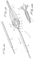
- FIGS 12-17 Alternate examples of a guidewire containing a self-expanding distal protection device are illustrated in Figures 12-17 .
- the membrane automatically expands when deployed from the catheter as a result of the shape memory or springiness characteristics of the wire underlying the membrane.
- a 0.46 mm (.018 inch) diameter wire can be utilized by way of example, it being understood that wire of other dimensions could be used.
- distal protection device 70 comprises a membrane or bag 80 and a guidewire 71 having a guidewire extension 72, illustratively of a larger diameter, extending from its distal end.
- a membrane 80 preferably made of PET, is welded to region 74 of the extension 72.
- a series of wires 76 preferably composed of shape memory material such as Nitinol, a nickel titanium alloy, extends past the distal end 75 of the guidewire 70 and are welded thereto. Alternately, other materials such as stainless steel with sufficient springiness could be utilized.
- Four wires are shown but a different number to expand the membrane could be provided.
- the distal end of the wires 76 are connected to a proximal end 73 of extension 72.
- Each of the wires curves in the expanded condition as shown.
- Guidewire 71 is shown by way of example comprising a wound coil around the four wires 76. However, alternately the wires can extend only from the distal end of the guidewire.
- a flexible mounting ring or band 82 is attached to the proximal end of the membrane 80, at the mouth, and is attached, e.g. welded, to the wires 76.
- the ring 82 can also be composed of shape memory material to automatically expand when deployed or alternatively of other flexible material to expand when the shape memory wires move to their expanded memorized position.
- the wires 76 and membrane 80 are retained in a collapsed position within catheter 79 for delivery as illustrated in Figure 12 .
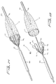
- the wires 76 When catheter 79 is pulled proximally in the direction of the arrow, the wires 76 are exposed from the catheter 79, and automatically expand to the memorized position shown in Figure 13 . As they expand they move the membrane 80 from a contracted position to the expanded position of Figure 13 aided by expansion of band 82. Embolic material flowing through the mouth 84 of the membrane 80 will be captured in the membrane 80, with the blood flowing through the membrane pores.
- the wires 76 can be fully or partially withdrawn into the catheter 79, or the catheter advanced partially or fully over the wires 76, thus collapsing at least the mouth of the membrane to contain the embolic material therein as the device is withdrawn.
- a 5-7 French catheter can be used by way of example.
- wires for attaching the membrane are illustrated.
- the wires are also preferably made of shape memory material and form part of the guidewire. They can extend the length of the guidewire as in Figure 13A or alternatively only extend from the distal end.
- the porous membrane is attached only at the end portions of the wires 96, thereby reducing the presence of wires in the flow path.
- guidewire 93 of distal protection device 90 has four looped wires 96 extending from region 95 and connected to band or ring 97 of membrane 91 at bend points 98. Membrane 91 is attached at its distal end 94 to guidewire extension 92.
- each wire 96" has a curved wire section 92" and a looped section 93" extending from a distal end of the wire section 92" forming a bend point 95" for attachment to the band 97" of membrane 91".
- These looped wires function in the same manner as in the Figure 12 as they are preferably composed of shape memory material so that membrane expansion occurs upon release of the wires from the catheter and collapse of the wires by the catheter closes the membrane to withdraw the device.
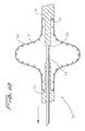
- Figures 18 and 19 illustrate an alternate examples of a distal protection device.
- Wire 102 of distal protection device 100 expands to a coiled shape as shown to expand a porous membrane 104 into a substantially spherical shape.
- Wire 102 wraps around the outer surface of the guidewire 105 and forms several loops when expanded. More than one wire could optionally be used.
- wire 102' is offset for positioning on one side of the guidewire 105' such that expansion of the membrane 104' provides a larger region for blood flow and a wider opening in membrane 104' for capture of material.
- Wire 102' loops around the outer surface of guidewire 105, forming a plurality of loops of progressively increasing diameter toward the proximal end and proximal opening 107 in the membrane 104'.
- the wires 102, 102' are preferably composed of shape memory material (or springy material) so they expand to the coiled (looped) position when deployed from catheter 110.
- the wires 102, 102' assume a substantially linear configuration within catheter 110 to maintain a low profile for delivery. When exposed from catheter 110, the wire assumes its coiled shape to expand the membrane 104, 104' to a radially deployed position as shown.
- other filtering material can be utilized.
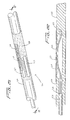
- FIG. 21-24 an embodiment of the distal protection device of the present invention is shown and represented generally by reference numeral 110.
- a flexible member such as a wire 112 is seated within slot 120 formed in the sidewall of tube 122 and is attached at its distal end 114 to the tube 122 and at its proximal end 116 to slidable tube or shaft 118.
- a filtering material such as porous membrane 126 covers a region of the tube and the slot 120.
- the wire 112 In the collapsed position, the wire 112 is preferably fully contained within the tube 122 to reduce the overall insertion profile. In this collapsed position it is in alignment with the slot 120 and the membrane 126 is collapsed around the tube 122.
- a 0.13 mm (.005 inch) diameter wire can be utilized although wires of other dimensions could also be used.
- slidable member such as shaft or tube 118 is advanced in a distal direction (see arrow of Figure 24 ) to deploy the wire 112 laterally to bend into a loop extending transversely to a longitudinal axis of the tube 122.
- End 117 extends proximally and end 119 extends distally.
- the expanded loop thus lies in a plane at an angle to both the longitudinal axis and transverse axis of the catheter.
- the plane of the loop opening would be at an angle (preferably at a slight angle) to the longitudinal and transverse axis of tube 122.
- the wire 112 would thus extend such that the loop opening is slightly offset from the direction of the longitudinal axis of tube 122 but still open generally in the direction of blood flow. That is, a central longitudinal axis extending through the loop opening would be at an angle with respect to the longitudinal axis of the tube 122.
- the plane of the loop opening is perpendicular to the longitudinal axis of the catheter (parallel to the transverse axis) and perpendicular to the direction of blood flow. In other embodiments, rather than perpendicular, the plane of the loop opening is at an angle less than 90 degrees, but preferably greater than about 45 degrees to the longitudinal axis.
- the formation of the wire loop stretches the membrane 126 on one side of the catheter to the illustrated expanded configuration of Figures 23 and 24 to block the flow of material. This provides additional coverage of the vessel lumen as the catheter can be placed adjacent the internal wall of the vessel with the membrane 126 filling the space above.
- the windows 127 of membrane 126 provide enlarged openings for blood flow, with the membrane 126 blocking flow of materials exceeding the pore size.
- the shaft 118 is moved proximally to retract the loop and membrane to the initial low profile insertion position.
- the membrane 126 is made of a material that would return automatically from its stretched position to the original collapsed position when the wire is retracted. This passive self-contraction would avoid the need for insertion of a separate device over the membrane to cover it for removal, thus reducing the overall profile of the instrumentation necessary for the procedure. That is, in the preferred embodiment the wire is expanded by active control while the membrane would automatically retract without other assistance.
- the membrane can be attached to wire 112 and move with the wire 112.
- a flexible member in the form of a wire 131 of distal protection device 130 forms two looped wire regions 132, 134 when expanded so the filtering material such as membrane 136 stretches in two directions.
- slidable actuating member such as tube or shaft 138 is advanced distally in the direction of the arrow, the wire 131 bends to extend further through slot 144 in the sidewall of the catheter 142, forming the first looped wire region 132 on one side of catheter 142 and the second looped wire region 134 on the other side of the catheter 142, preferably about 180 degrees apart.
- This double looped configuration causes membrane 136 to be stretched on opposing sides of the tube 142 to filter materials.
- the loops are open generally in a direction of blood flow (the plane of the loop opening is substantially transverse to the direction of blood flow and substantially transverse to the longitudinal axis of the device) with blood flowing through windows 137 of membrane 136.
- the wire can be configured so the two looped sections are axially offset as shown in Fig. 28 . That is, the loop sections 162, 164 of wire 161 of distal protection device 160 are axially displaced so that loop 162 is positioned distal of loop section 164.
- advancement of tube or shaft 172 deploys wire 161 through the slot in the sidewall of tube 174 to assume the looped configuration and stretch porous membrane 176 to the deployed configuration on both sides of tube 174.
- a double loop configuration of distal protection device 180 is achieved on each side of the tube 192.
- the flexible member in the form of wire 181 extends through slot 194 of tube 192, forming two loops on each side of tube 192 to stretch membrane (filtering material) 186 when tube or shaft 188 is moved distally. That is, in the expanded configuration, wire 181 extends out of slot 194 to form first loop 185 on a first side of the tube 192, then extends to form second loop 183 on a second opposing side of tube 192, extends upwardly (as viewed in the orientation of Fig.
- loop openings are generally in the direction of blood flow with the plane of the loop openings substantially transverse to the direction of the blood flow.
- Porous membrane 186 has windows 189.
- the loop opening can be in a plane perpendicular or at an angle less than 90 degrees to the longitudinal axis, but preferably greater than about 45 degrees.
- Figure 29 shows the positioning of the distal protection device of the present invention.
- device 130 of Figure 26 is shown deployed in the carotid artery "c", it being understood that the other devices described herein can be placed in the same location.
- the catheter 200 is inserted through the femoral vein “f” as shown in Figure 24 and advanced to the carotid artery "c". Once positioned at the desired site, catheter 200 is retracted to expose the device 130, or alternately the device 130 is advanced from the catheter 200. Once exposed at the site, the tube is advanced as described above to deploy the wire to the looped configuration to expand membrane 136 to block emboli in the artery.
- the wire can include radiopaque material for imaging.
Description
- This application relates to a vascular device in the form of a distal protection device and more particularly to a vascular device for capturing embolic material during surgical procedures.
- During vascular surgical procedures such as stenting, angioplasty, thrombectomy, and atherectomy, embolic material such as plaque and blood clots can become dislodged. Dislodgement of such embolic material can cause the emboli to flow downstream to lodge in the vascular system, thereby occluding flow of oxygenated blood to the brain or other vital organs. Such occlusion can compromise peripheral circulation or result in heart attack, stroke or even death.
- Techniques to cut the debris into smaller sizes, such as by use of lasers, have had significant drawbacks, such as the inability to ensure all the debris is cut into sufficiently small fragments. If some of the fragments remain too large, then occlusion of the vessels can occur causing the problems and risks enumerated above.
- Attempts have been made to place a device distal (downstream) of the stenosis, thrombus, etc. to capture the emboli. Such distal protection devices typically are collapsible for insertion and expandable once in the vessel. Some devices are in the form of an expandable balloon which is inserted within the vessel inside a sheath. When the sheath is withdrawn, the balloon is expanded to block emboli. These balloon devices even in the collapsed position increase the profile of the device since they are wrapped on the outside of the device. In other distal protection devices, a wire is covered by a membrane. These wires extend laterally from the device and may not enable the membrane to block the entire region of the vessel. Failure to expand to geometry to block the entire region can result in the unwanted passage of debris which can cause vessel occlusion and the aforementioned adverse consequences.
-
US2002/0002384 describes an embolic protection device which has a collapsible filter element mounted on a carrier such as a guidewire. The filter element collapses into an outer end of a catheter for deployment and retrieval through a vascular system of a patient. - It is an object of the present invention to provide an improved distal protection device. Such device would have a reduced profile to facilitate insertion and to better enable placement of the device distal of the emboli to block potential downstream flow. The device would also be easy to manipulate and sufficiently fill the vessel area to ensure all passage is blocked.
- According to the present invention there is provided a distal protection device comprising a catheter having a cylindrical wall, a flexible member movable from a first retracted position to a second looped position extending laterally with respect to the catheter, and filtering material movable from a collapsed position to an expanded position in response to movement of the flexible member, wherein in the second looped position a first loop opening extends substantially in a direction of blood flow as the first loop opening lies in a plane substantially parallel to a transverse axis of the catheter, and wherein a slot is formed in a sidewall of the catheter, the flexible member extending through the slot when moved to the second looped position.
- The flexible member may be contained within the catheter in the first position so the cross sectional dimension of the catheter at a portion containing the flexible member does not exceed other cross-sectional dimensions of the catheter.
- The flexible member may loop in a plane perpendicular to the longitudinal axis of the catheter.
- The device may further comprise a second loop spaced from the first loop and movable from a first retracted position to a second looped position extending laterally with respect to the catheter.
- In the looped position, two radially spaced loops may be formed.
- The loops may extend in opposite directions with respect to the catheter so in the looped position the loops are approximately 180 degrees apart.
- The loops may be axially offset.
- The device may further comprise an actuating member movable from a first position to a second position to move the flexible member into the looped position.
- The filtering material may automatically moves back from the expanded position to the collapsed position upon movement of the actuating member back to the first position.
- The flexible member may be a wire wherein, in the second position, a first end of the wire extends in a proximal direction and a second end of the wire extends in a distal direction with the loop therebetween having an opening extending in a proximal to distal direction.
- The wire may form a second loop in the second position.
- The filter material may automatically move from the expanded position to the collapsed position upon movement of the flexible member back to the first position.
- Preferred embodiment(s) of the present disclosure are described herein with reference to the drawings wherein:
-
Figures 1-5 illustrate a distal protection device, wherein-
Figure 1 is a perspective view; -
Figure 2 is a cross-sectional view taken along lines 2-2 ofFigure 1 ; -
Figure 3 is a perspective view showing the outer tube withdrawn to enable expansion of the balloons; -
Figure 4 is a perspective view illustrating the inner and outer balloons in the expanded configuration; and -
Figure 5 is a side view in partial cross section showing the balloons expanded;
-
-
Figure 6 is a perspective view of a distal protection device, having a self-expanding umbrella device; -
Figure 7 is a perspective view of the device ofFigure 6 showing the umbrella device expanded by blood flow; -
Figures 8 and 9 are perspective and longitudinal cross-sectional views, respectively, of another distal protection device, having a membrane formed over a coiled wire, the membrane and wire shown in the retracted insertion position; -
Figure 9A is an enlarged longitudinal cross-sectional view of a portion of the catheter ofFigure 9 ; -
Figure 10 is a view similar toFigure 9A except showing the wire and membrane in the expanded position; -
Figure 11 is a perspective view of the device in the expanded position ofFigure 10 ; -
Figures 12 and 13 are perspective views of a further distal protection device, having a membrane fused to a shape memory wire, whereinFigure 12 shows the shape memory wire and membrane contained within the catheter andFigure 13 shows the shape memory wire advanced from the catheter to open the membrane to an expanded position; -
Figure 13A is an enlarged view of the area of detail ofFigure 13 ; -
Figures 14-17 illustrate three alternate examples of the device ofFigure 12 , showing varying shape memory wire configurations fused to a membrane wherein;-
Figures 14 and 15 are perspective views showing looped wires, withFigure 14 showing the attachment to the membrane ring andFigure 15 showing an exploded view; -
Figure 16 is an exploded view showing looped wires with pointed bend points; and -
Figure 17 is an exploded view showing individual wire segments terminating in rings;
-
-
Figures 18 and 19 are perspective and side views, respectively, of another alternate distal protection device having a membrane attached to a coiled wire and shown in the expanded position; -
Figure 20 is a side view of an alternate device ofFigure 18 wherein the coiled wire for deploying the membrane extends on one side of the guidewire; -
Figures 21 and 22 are respectively perspective and longitudinal cross-sectional views (taken along lines 22-22) of an embodiment of a distal protection device according to the present invention and having a single wire loop for deploying the membrane, the membrane and wire shown in the non-expanded (collapsed) position; -
Figures 23 and 24 are respectively perspective and longitudinal cross-sectional views (taken along lines 24-24) similar toFigures 21 and 22 except illustrating the wire in the looped position and membrane in the deployed position; -
Figure 24A is an end view of the device ofFigure 23 ; -
Figure 25 and 26 are perspective views of yet another alternate embodiment of the distal protection device according to the present invention as shownFigure 21 , the device having a double looped wire for deploying the membrane, the membrane shown in the non-expanded position inFig. 25 and the deployed position inFig. 26 ; -
Figure 27 is a perspective view illustrating another alternate embodiment of the distal protection device according to the present invention as shown inFigure 21 , the device having multiple wire loops, the membrane shown in the deployed position; -
Figure 28 is a perspective view of an alternate embodiment of the distal protection device according to the present invention as shown inFigure 26 wherein the wire loops are axially offset; and -
Figures 29 and 29A illustrate placement of the device ofFigure 26 , whereinFigure 29 shows the catheter advanced through the femoral to the carotid artery andFigure 29A shows the device deployed in the carotid artery to block distal flow of emboli. - Referring now in detail to the drawings where like reference numerals identify similar or like components throughout the several views, several different embodiments for capturing embolic material during surgical procedures.
- Turning first to the examples of
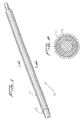
Figures 1-5 , acatheter 10 has anouter tube 12, a coaxialinner core 14 disposed in theouter tube 12, aninner balloon filter 16 and anouter balloon filter 18. Thetube 12 andcore 14 are preferably composed of Nitinol, with the core preferably having a platinum wind therearound, however other materials such as stainless steel are also contemplated. Theinner balloon filter 16, preferably made of polyurethane, is attached to thecatheter 10 at a distal end viaring 29.Balloon 16 hassmall holes 17 dimensioned for filtering embolic material. Theholes 17 are preferably 180 microns, although other dimensions are contemplated.Outer filter balloon 18, also preferably made of PET, is attached at a distal end tocatheter 10 viaring 22. As shown,outer filter balloon 18 is external of inner filter balloon 20.Balloon 18 also has a series ofholes 19 for filtering embolic material. The holes of theouter balloon 18 are preferably smaller than those of theinner balloon 16 to capture embolic material filtering through theinner balloon 16. In one example, theholes 19 of the outer balloon are 120 microns, although other dimensions are contemplated. Mountingring 26 supports proximal ends ofballoons - In use, the space between the
balloons Figures 4 and5 . The inner andouter balloons holes - Thus, embolic material exceeding a certain size carried by the blood through the proximal opening in the balloons is captured in the balloon filters 16, 18, with the blood and smaller particles flowing through the
holes -
Figures 8-10 illustrate an alternate example of the distal protection device, designated generally byreference numeral 30. In this example, the blocking membrane is deployed by mechanical actuation of a wire or shaft. More specifically,catheter 31 has a coiledwire 32 attached at a distal end to endwall 37 oftip 34 and at its proximal end to wall 36 by means such as welding. Anactuation shaft 38, or alternatively a wire, is slidably positioned within a bore in thecatheter 31 and is attached at adistal end 39 toproximal extension 35 oftip 34. Aporous membrane 40 is positioned over the coiledwire 32. Themembrane 40 can be attached at a proximal end to wall 36 and at a distal end to wall 37 oftip 34.Membrane 40 may also be attached to coiledwire 32. As shown, themembrane 40 fully covers the distal portion of thewire 32 and has enlarged open regions or windows, defined betweenelongated strips 42, to allow entry of blood. - To deploy the
membrane 40 ofdistal protection device 30 from a low profile insertion position ofFigures 8 and 9 to an expanded configuration ofFigure 10 to block particles,actuation shaft 38 is pulled proximally (in the direction of the arrow ofFigure 10 ), thereby pullingtip 34 proximally. Such retraction oftip 34, forces the coiledwire 32 to compress and extend radially outwardly as shown, thereby forcing themembrane 40 radially to a stretched or expanded configuration to block and capture flow of embolic material. The pores in theextended membrane 40 enable blood flow therethrough while capturing embolic material exceeding a predetermined size, i.e. the size of the pores in the membrane. To remove thedevice 30,actuation shaft 38 is pushed distally to retract thewire 32 andcollapse membrane 40. - It should be appreciated that instead of a coiled wire, a tubular braid could be provided with a membrane, e.g. of urethane material, over the braid. The braid would be attached to the catheter and moved between retracted and expanded positions in a similar manner as
wire 32. The braided version could alternately be obtained by providing a braided catheter and etching a section of the outer plastic to expose the braid. -
Figures 6 and7 illustrate a self expandingdistal protection device 50. The self-expansion occurs as a result of blood flow. Thedistal protection device 50 is an umbrella type device attached to adistal region 51 ofguidewire 52. Theguidewire 52 is shown with a reduced diameterdistal portion 53. The umbrella is in the form of aporous balloon 54, preferably composed of polyurethane, although other materials are also contemplated. A suture loop orring 56 is attached to aproximal end 51 of theballoon 54 and asuture 58 extends proximally from thesuture loop 56. In use, the device is inserted with theballoon 54 in the collapsed low profile position ofFigure 6 . When thedevice 50 is exposed from the catheter or sheath, either by advance ofdevice 50 or retraction of the catheter or sheath, blood flow will expand theballoon 54 to the position shown inFigure 7 with the mouth 59 open in a proximal direction. The blood will flow through the holes (pores) 55 in theballoon 54, with the embolic material exceeding the size of the pores being captured within theballoon 54. At the end of the procedure, thesuture 58 is pulled proximally to flatten and close the mouth 59 of theballoon 54, thus capturing the embolic material inside. The reduced profile of the flattened balloon enables withdrawal of the device through the catheter or sheath. - Being part of a guidewire, in use, the
device 50 ofFigure 6 could be placed within the catheter after the guidewire for introducing the catheter is withdrawn. The catheter can then be withdrawn and another catheter, such as a stent delivery catheter could be inserted over theguidewire 52. - Alternate examples of a guidewire containing a self-expanding distal protection device are illustrated in
Figures 12-17 . However, rather than expansion by blood flow, the membrane automatically expands when deployed from the catheter as a result of the shape memory or springiness characteristics of the wire underlying the membrane. A 0.46 mm (.018 inch) diameter wire can be utilized by way of example, it being understood that wire of other dimensions could be used. - Turning first to the examples of
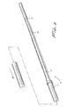
Figures 12 and 13 ,distal protection device 70 comprises a membrane orbag 80 and aguidewire 71 having aguidewire extension 72, illustratively of a larger diameter, extending from its distal end. Amembrane 80, preferably made of PET, is welded toregion 74 of theextension 72. A series ofwires 76, preferably composed of shape memory material such as Nitinol, a nickel titanium alloy, extends past thedistal end 75 of theguidewire 70 and are welded thereto. Alternately, other materials such as stainless steel with sufficient springiness could be utilized. Four wires are shown but a different number to expand the membrane could be provided. The distal end of thewires 76 are connected to aproximal end 73 ofextension 72. Each of the wires curves in the expanded condition as shown.Guidewire 71 is shown by way of example comprising a wound coil around the fourwires 76. However, alternately the wires can extend only from the distal end of the guidewire. A flexible mounting ring orband 82 is attached to the proximal end of themembrane 80, at the mouth, and is attached, e.g. welded, to thewires 76. Thering 82 can also be composed of shape memory material to automatically expand when deployed or alternatively of other flexible material to expand when the shape memory wires move to their expanded memorized position. Thewires 76 andmembrane 80 are retained in a collapsed position withincatheter 79 for delivery as illustrated inFigure 12 . - When
catheter 79 is pulled proximally in the direction of the arrow, thewires 76 are exposed from thecatheter 79, and automatically expand to the memorized position shown inFigure 13 . As they expand they move themembrane 80 from a contracted position to the expanded position ofFigure 13 aided by expansion ofband 82. Embolic material flowing through themouth 84 of themembrane 80 will be captured in themembrane 80, with the blood flowing through the membrane pores. At the end of the procedure, thewires 76 can be fully or partially withdrawn into thecatheter 79, or the catheter advanced partially or fully over thewires 76, thus collapsing at least the mouth of the membrane to contain the embolic material therein as the device is withdrawn. A 5-7 French catheter can be used by way of example. - In
Figures 14-17 , three alternate examples of wires for attaching the membrane are illustrated. In these embodiments, the wires are also preferably made of shape memory material and form part of the guidewire. They can extend the length of the guidewire as inFigure 13A or alternatively only extend from the distal end. In these examples, the porous membrane is attached only at the end portions of thewires 96, thereby reducing the presence of wires in the flow path. InFigures 14 and 15 , guidewire 93 ofdistal protection device 90 has four loopedwires 96 extending fromregion 95 and connected to band orring 97 ofmembrane 91 at bend points 98.Membrane 91 is attached at itsdistal end 94 toguidewire extension 92. Upon deployment fromcatheter 99,wires 96 move to their memorized position to expandmembrane 91. InFigure 16 , shape memory looped wires 96' have more pointed bend points 98' for attachment to the band 97' of membrane 91'. Otherwise, the device 90' is identical todistal protection device 90 ofFigure 15 . In theFigure 17 , eachwire 96" has acurved wire section 92" and a loopedsection 93" extending from a distal end of thewire section 92" forming abend point 95" for attachment to theband 97" ofmembrane 91". These looped wires function in the same manner as in theFigure 12 as they are preferably composed of shape memory material so that membrane expansion occurs upon release of the wires from the catheter and collapse of the wires by the catheter closes the membrane to withdraw the device. -
Figures 18 and 19 illustrate an alternate examples of a distal protection device.Wire 102 ofdistal protection device 100 expands to a coiled shape as shown to expand aporous membrane 104 into a substantially spherical shape.Wire 102 wraps around the outer surface of theguidewire 105 and forms several loops when expanded. More than one wire could optionally be used. InFigure 20 , wire 102' is offset for positioning on one side of the guidewire 105' such that expansion of the membrane 104' provides a larger region for blood flow and a wider opening in membrane 104' for capture of material. Wire 102' loops around the outer surface ofguidewire 105, forming a plurality of loops of progressively increasing diameter toward the proximal end andproximal opening 107 in the membrane 104'. Thewires 102, 102' are preferably composed of shape memory material (or springy material) so they expand to the coiled (looped) position when deployed fromcatheter 110. Thewires 102, 102' assume a substantially linear configuration withincatheter 110 to maintain a low profile for delivery. When exposed fromcatheter 110, the wire assumes its coiled shape to expand themembrane 104, 104' to a radially deployed position as shown. Besides a membrane, as with each of the embodiments described herein, other filtering material can be utilized. - In
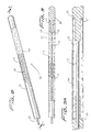
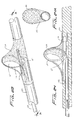
Figures 21-24 , an embodiment of the distal protection device of the present invention is shown and represented generally byreference numeral 110. A flexible member such as awire 112 is seated withinslot 120 formed in the sidewall oftube 122 and is attached at itsdistal end 114 to thetube 122 and at itsproximal end 116 to slidable tube orshaft 118. A filtering material such asporous membrane 126 covers a region of the tube and theslot 120. In the collapsed position, thewire 112 is preferably fully contained within thetube 122 to reduce the overall insertion profile. In this collapsed position it is in alignment with theslot 120 and themembrane 126 is collapsed around thetube 122. A 0.13 mm (.005 inch) diameter wire can be utilized although wires of other dimensions could also be used. - To deploy the device, slidable member such as shaft or
tube 118 is advanced in a distal direction (see arrow ofFigure 24 ) to deploy thewire 112 laterally to bend into a loop extending transversely to a longitudinal axis of thetube 122.End 117 extends proximally and end 119 extends distally. The expanded loop thus lies in a plane at an angle to both the longitudinal axis and transverse axis of the catheter. In other words, the plane of the loop opening would be at an angle (preferably at a slight angle) to the longitudinal and transverse axis oftube 122. Thewire 112 would thus extend such that the loop opening is slightly offset from the direction of the longitudinal axis oftube 122 but still open generally in the direction of blood flow. That is, a central longitudinal axis extending through the loop opening would be at an angle with respect to the longitudinal axis of thetube 122. - Consequently, in one embodiment, the plane of the loop opening is perpendicular to the longitudinal axis of the catheter (parallel to the transverse axis) and perpendicular to the direction of blood flow. In other embodiments, rather than perpendicular, the plane of the loop opening is at an angle less than 90 degrees, but preferably greater than about 45 degrees to the longitudinal axis.
- The formation of the wire loop stretches the
membrane 126 on one side of the catheter to the illustrated expanded configuration ofFigures 23 and 24 to block the flow of material. This provides additional coverage of the vessel lumen as the catheter can be placed adjacent the internal wall of the vessel with themembrane 126 filling the space above. Thewindows 127 ofmembrane 126 provide enlarged openings for blood flow, with themembrane 126 blocking flow of materials exceeding the pore size. - To withdraw the device, the
shaft 118 is moved proximally to retract the loop and membrane to the initial low profile insertion position. In a preferred embodiment, themembrane 126 is made of a material that would return automatically from its stretched position to the original collapsed position when the wire is retracted. This passive self-contraction would avoid the need for insertion of a separate device over the membrane to cover it for removal, thus reducing the overall profile of the instrumentation necessary for the procedure. That is, in the preferred embodiment the wire is expanded by active control while the membrane would automatically retract without other assistance. - In another embodiment, the membrane can be attached to
wire 112 and move with thewire 112. - Other materials for the embodiments of
Figures 21-28 can be utilized which as inmembrane 126 would be movable between collapsed and deployed positions. - In the embodiment of the distal protection device of the present invention as shown in
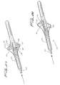
Figures 25 and 26 , a flexible member in the form of awire 131 ofdistal protection device 130 forms two loopedwire regions membrane 136 stretches in two directions. When slidable actuating member such as tube orshaft 138 is advanced distally in the direction of the arrow, thewire 131 bends to extend further throughslot 144 in the sidewall of thecatheter 142, forming the first loopedwire region 132 on one side ofcatheter 142 and the second loopedwire region 134 on the other side of thecatheter 142, preferably about 180 degrees apart. This double looped configuration causesmembrane 136 to be stretched on opposing sides of thetube 142 to filter materials. As in the embodiment ofFigure 23 , the loops are open generally in a direction of blood flow (the plane of the loop opening is substantially transverse to the direction of blood flow and substantially transverse to the longitudinal axis of the device) with blood flowing throughwindows 137 ofmembrane 136. - Although shown in axial alignment in
Fig. 26 , alternatively the wire can be configured so the two looped sections are axially offset as shown inFig. 28 . That is, theloop sections 162, 164 ofwire 161 ofdistal protection device 160 are axially displaced so that loop 162 is positioned distal ofloop section 164. As in the previous embodiment, advancement of tube orshaft 172 deployswire 161 through the slot in the sidewall oftube 174 to assume the looped configuration and stretchporous membrane 176 to the deployed configuration on both sides oftube 174. - In
Fig. 27 , a double loop configuration of distal protection device 180 according to the present invention is achieved on each side of the tube 192. The flexible member in the form ofwire 181 extends throughslot 194 of tube 192, forming two loops on each side of tube 192 to stretch membrane (filtering material) 186 when tube orshaft 188 is moved distally. That is, in the expanded configuration,wire 181 extends out ofslot 194 to form first loop 185 on a first side of the tube 192, then extends to formsecond loop 183 on a second opposing side of tube 192, extends upwardly (as viewed in the orientation ofFig. 27 ) to form third loop 182 on the first side, and then extends to form fourth loop 184 on the second side, after which it extends back throughslot 194. As in the other embodiments the loop openings are generally in the direction of blood flow with the plane of the loop openings substantially transverse to the direction of the blood flow.Porous membrane 186 has windows 189. - As noted above, in these embodiments of
Figures 21-27 , the loop opening can be in a plane perpendicular or at an angle less than 90 degrees to the longitudinal axis, but preferably greater than about 45 degrees. -
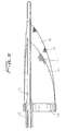
Figure 29 shows the positioning of the distal protection device of the present invention. By way of example,device 130 ofFigure 26 is shown deployed in the carotid artery "c", it being understood that the other devices described herein can be placed in the same location. Thecatheter 200 is inserted through the femoral vein "f" as shown inFigure 24 and advanced to the carotid artery "c". Once positioned at the desired site,catheter 200 is retracted to expose thedevice 130, or alternately thedevice 130 is advanced from thecatheter 200. Once exposed at the site, the tube is advanced as described above to deploy the wire to the looped configuration to expandmembrane 136 to block emboli in the artery. - While the above description contains many specifics, those specifics should not be construed as limitations on the scope of the disclosure, but merely as exemplifications of preferred embodiments thereof. For example, the wire can include radiopaque material for imaging.
Claims (12)
- A distal protection device comprising a catheter (142, 200) having a cylindrical wall, a flexible member (112, 131, 161, 181) movable from a first retracted position to a second looped position extending laterally with respect to the catheter, and filtering material (126, 136, 176, 186) movable from a collapsed position to an expanded position in response to movement of the flexible member, characterized in that in the second looped position a first loop opening extends substantially in a direction of blood flow as the first loop opening lies in a plane substantially parallel to a transverse axis of the catheter, and in that a slot (120, 144, 194) is formed in a sidewall of the catheter, the flexible member (112, 131, 161, 181) extending through the slot when moved to the second looped position.
- A device as claimed in claim 1, characterized in that the flexible member (112, 131, 161, 181) is contained within the catheter (142, 200) in the first position so the cross sectional dimension of the catheter at a portion containing the flexible member does not exceed other cross-sectional dimensions of the catheter.
- A device as claimed in any preceding claim, characterized in that the flexible member (112, 131, 161, 181) loops in a plane perpendicular to the longitudinal axis of the catheter (142, 200).
- A device as claimed in any preceding claim, characterized in that the device further comprises a second loop (134) spaced from the first loop (132) and movable from a first retracted position to a second looped position extending laterally with respect to the catheter (142, 200).
- A device as claimed in any preceding claim, characterized in that, in the looped position, two radially spaced loops (132, 134) are formed.
- A device as claimed in claim 4 or 5, characterized in that the loops (132, 134) extend in opposite directions with respect to the catheter (142, 200) so in the looped position the loops are approximately 180 degrees apart.
- A device as claimed in claim 4, 5 or 6, characterized in that the loops (32, 102, 102') are axially offset.
- A device as claimed in any preceding claim, characterized in that the device further comprises an actuating member (118, 138, 172) movable from a first position to a second position to move the flexible member (112, 131, 161, 181) into the looped position.
- A device as claimed in claim 8, characterized in that the filtering material (126, 136, 176, 186) automatically moves back from the expanded position to the collapsed position upon movement of the actuating member (118, 138, 172) back to the first position.
- A device as claimed in any preceding claim, characterized in that the flexible member (112, 131, 161, 181) is a wire wherein, in the second position, a first end of the wire extends in a proximal direction and a second end of the wire extends in a distal direction with the loop therebetween having an opening extending in a proximal to distal direction.
- A device as claimed in claim 10, characterized in that the wire forms a second loop in the second position.
- A device as claimed in any preceding claim, characterized in that the filter material (126, 136, 176, 186) automatically moves from the expanded position to the collapsed position upon movement of the flexible member (112, 131, 161, 181) back to the first position.
Applications Claiming Priority (3)
| Application Number | Priority Date | Filing Date | Title |
|---|---|---|---|
| US46649103P | 2003-04-29 | 2003-04-29 | |
| US10/800,299 US7604649B2 (en) | 2003-04-29 | 2004-03-12 | Distal protection device |
| PCT/US2004/012356 WO2004096089A2 (en) | 2003-04-29 | 2004-04-22 | Distal protection device |
Publications (2)
| Publication Number | Publication Date |
|---|---|
| EP1620036A2 EP1620036A2 (en) | 2006-02-01 |
| EP1620036B1 true EP1620036B1 (en) | 2009-10-14 |
Family
ID=33423612
Family Applications (1)
| Application Number | Title | Priority Date | Filing Date |
|---|---|---|---|
| EP04750453A Expired - Fee Related EP1620036B1 (en) | 2003-04-29 | 2004-04-22 | Distal protection device |
Country Status (7)
| Country | Link |
|---|---|
| US (1) | US7604649B2 (en) |
| EP (1) | EP1620036B1 (en) |
| JP (1) | JP2006525082A (en) |
| AU (1) | AU2004233843A1 (en) |
| CA (1) | CA2522966A1 (en) |
| DE (1) | DE602004023598D1 (en) |
| WO (1) | WO2004096089A2 (en) |
Families Citing this family (131)
| Publication number | Priority date | Publication date | Assignee | Title |
|---|---|---|---|---|
| US8414543B2 (en) | 1999-10-22 | 2013-04-09 | Rex Medical, L.P. | Rotational thrombectomy wire with blocking device |
| US6575997B1 (en) * | 1999-12-23 | 2003-06-10 | Endovascular Technologies, Inc. | Embolic basket |
| US6402771B1 (en) | 1999-12-23 | 2002-06-11 | Guidant Endovascular Solutions | Snare |
| US6660021B1 (en) * | 1999-12-23 | 2003-12-09 | Advanced Cardiovascular Systems, Inc. | Intravascular device and system |
| US6540722B1 (en) * | 1999-12-30 | 2003-04-01 | Advanced Cardiovascular Systems, Inc. | Embolic protection devices |
| US7918820B2 (en) * | 1999-12-30 | 2011-04-05 | Advanced Cardiovascular Systems, Inc. | Device for, and method of, blocking emboli in vessels such as blood arteries |
| US6695813B1 (en) | 1999-12-30 | 2004-02-24 | Advanced Cardiovascular Systems, Inc. | Embolic protection devices |
| US20040167567A1 (en) * | 2001-03-23 | 2004-08-26 | Cano Gerald G. | Method and apparatus for capturing objects beyond an operative site in medical procedures |
| US6939362B2 (en) * | 2001-11-27 | 2005-09-06 | Advanced Cardiovascular Systems, Inc. | Offset proximal cage for embolic filtering devices |
| US6964670B1 (en) * | 2000-07-13 | 2005-11-15 | Advanced Cardiovascular Systems, Inc. | Embolic protection guide wire |
| US6527746B1 (en) * | 2000-08-03 | 2003-03-04 | Ev3, Inc. | Back-loading catheter |
| US6537294B1 (en) * | 2000-10-17 | 2003-03-25 | Advanced Cardiovascular Systems, Inc. | Delivery systems for embolic filter devices |
| US20060135947A1 (en) * | 2000-10-27 | 2006-06-22 | Pulmonx | Occlusal stent and methods for its use |
| US6893451B2 (en) * | 2000-11-09 | 2005-05-17 | Advanced Cardiovascular Systems, Inc. | Apparatus for capturing objects beyond an operative site utilizing a capture device delivered on a medical guide wire |
| US6506203B1 (en) * | 2000-12-19 | 2003-01-14 | Advanced Cardiovascular Systems, Inc. | Low profile sheathless embolic protection system |
| US6645223B2 (en) * | 2001-04-30 | 2003-11-11 | Advanced Cardiovascular Systems, Inc. | Deployment and recovery control systems for embolic protection devices |
| US6929652B1 (en) * | 2001-06-01 | 2005-08-16 | Advanced Cardiovascular Systems, Inc. | Delivery and recovery systems having steerability and rapid exchange operating modes for embolic protection systems |
| US6599307B1 (en) * | 2001-06-29 | 2003-07-29 | Advanced Cardiovascular Systems, Inc. | Filter device for embolic protection systems |
| US7338510B2 (en) * | 2001-06-29 | 2008-03-04 | Advanced Cardiovascular Systems, Inc. | Variable thickness embolic filtering devices and method of manufacturing the same |
| US20030032941A1 (en) * | 2001-08-13 | 2003-02-13 | Boyle William J. | Convertible delivery systems for medical devices |
| US6638294B1 (en) | 2001-08-30 | 2003-10-28 | Advanced Cardiovascular Systems, Inc. | Self furling umbrella frame for carotid filter |
| US6592606B2 (en) | 2001-08-31 | 2003-07-15 | Advanced Cardiovascular Systems, Inc. | Hinged short cage for an embolic protection device |
| US8262689B2 (en) * | 2001-09-28 | 2012-09-11 | Advanced Cardiovascular Systems, Inc. | Embolic filtering devices |
| US7241304B2 (en) | 2001-12-21 | 2007-07-10 | Advanced Cardiovascular Systems, Inc. | Flexible and conformable embolic filtering devices |
| US6887258B2 (en) * | 2002-06-26 | 2005-05-03 | Advanced Cardiovascular Systems, Inc. | Embolic filtering devices for bifurcated vessels |
| US7331973B2 (en) * | 2002-09-30 | 2008-02-19 | Avdanced Cardiovascular Systems, Inc. | Guide wire with embolic filtering attachment |
| US20040064099A1 (en) * | 2002-09-30 | 2004-04-01 | Chiu Jessica G. | Intraluminal needle injection substance delivery system with filtering capability |
| US7252675B2 (en) * | 2002-09-30 | 2007-08-07 | Advanced Cardiovascular, Inc. | Embolic filtering devices |
| US20040088000A1 (en) * | 2002-10-31 | 2004-05-06 | Muller Paul F. | Single-wire expandable cages for embolic filtering devices |
| US8591540B2 (en) * | 2003-02-27 | 2013-11-26 | Abbott Cardiovascular Systems Inc. | Embolic filtering devices |
| US20040172055A1 (en) * | 2003-02-27 | 2004-09-02 | Huter Scott J. | Embolic filtering devices |
| JP4845335B2 (en) * | 2003-05-21 | 2011-12-28 | キヤノン株式会社 | Data stream transmitting apparatus and data stream receiving apparatus |
| US7892251B1 (en) | 2003-11-12 | 2011-02-22 | Advanced Cardiovascular Systems, Inc. | Component for delivering and locking a medical device to a guide wire |
| US7678129B1 (en) | 2004-03-19 | 2010-03-16 | Advanced Cardiovascular Systems, Inc. | Locking component for an embolic filter assembly |
| US8403976B2 (en) * | 2004-04-08 | 2013-03-26 | Contego Medical Llc | Percutaneous transluminal angioplasty device with integral embolic filter |
| WO2006042114A1 (en) * | 2004-10-06 | 2006-04-20 | Cook, Inc. | Emboli capturing device having a coil and method for capturing emboli |
| US9510930B2 (en) | 2008-10-22 | 2016-12-06 | Contego Medical, Llc | Angioplasty device with embolic filter |
| US9707071B2 (en) | 2004-11-24 | 2017-07-18 | Contego Medical Llc | Percutaneous transluminal angioplasty device with integral embolic filter |
| US20060149313A1 (en) * | 2004-12-30 | 2006-07-06 | Edward Arguello | Distal protection apparatus with improved wall apposition |
| US20080015569A1 (en) | 2005-02-02 | 2008-01-17 | Voyage Medical, Inc. | Methods and apparatus for treatment of atrial fibrillation |
| US11478152B2 (en) | 2005-02-02 | 2022-10-25 | Intuitive Surgical Operations, Inc. | Electrophysiology mapping and visualization system |
| US9510732B2 (en) | 2005-10-25 | 2016-12-06 | Intuitive Surgical Operations, Inc. | Methods and apparatus for efficient purging |
| US8945169B2 (en) * | 2005-03-15 | 2015-02-03 | Cook Medical Technologies Llc | Embolic protection device |
| US9259305B2 (en) | 2005-03-31 | 2016-02-16 | Abbott Cardiovascular Systems Inc. | Guide wire locking mechanism for rapid exchange and other catheter systems |
| US8187298B2 (en) | 2005-08-04 | 2012-05-29 | Cook Medical Technologies Llc | Embolic protection device having inflatable frame |
| US8377092B2 (en) | 2005-09-16 | 2013-02-19 | Cook Medical Technologies Llc | Embolic protection device |
| US8632562B2 (en) | 2005-10-03 | 2014-01-21 | Cook Medical Technologies Llc | Embolic protection device |
| US8182508B2 (en) | 2005-10-04 | 2012-05-22 | Cook Medical Technologies Llc | Embolic protection device |
| US20070088382A1 (en) * | 2005-10-13 | 2007-04-19 | Bei Nianjiong J | Embolic protection recovery catheter assembly |
| US8252017B2 (en) | 2005-10-18 | 2012-08-28 | Cook Medical Technologies Llc | Invertible filter for embolic protection |
| US8216269B2 (en) | 2005-11-02 | 2012-07-10 | Cook Medical Technologies Llc | Embolic protection device having reduced profile |
| US8152831B2 (en) | 2005-11-17 | 2012-04-10 | Cook Medical Technologies Llc | Foam embolic protection device |
| US20070179519A1 (en) * | 2006-01-27 | 2007-08-02 | Wang Huisun | Stent delivery system to improve placement accuracy for self-expanding stent |
| US8500772B2 (en) * | 2006-03-20 | 2013-08-06 | Cook Medical Technologies Llc | Distal protection device |
| US9055906B2 (en) | 2006-06-14 | 2015-06-16 | Intuitive Surgical Operations, Inc. | In-vivo visualization systems |
| US10004388B2 (en) | 2006-09-01 | 2018-06-26 | Intuitive Surgical Operations, Inc. | Coronary sinus cannulation |
| US20080097476A1 (en) | 2006-09-01 | 2008-04-24 | Voyage Medical, Inc. | Precision control systems for tissue visualization and manipulation assemblies |
| US8758229B2 (en) | 2006-12-21 | 2014-06-24 | Intuitive Surgical Operations, Inc. | Axial visualization systems |
| US8480702B2 (en) * | 2007-01-11 | 2013-07-09 | Covidien Lp | Convertible embolic protection devices and methods of use |
| US9901434B2 (en) * | 2007-02-27 | 2018-02-27 | Cook Medical Technologies Llc | Embolic protection device including a Z-stent waist band |
| US8216209B2 (en) | 2007-05-31 | 2012-07-10 | Abbott Cardiovascular Systems Inc. | Method and apparatus for delivering an agent to a kidney |
| US7867273B2 (en) | 2007-06-27 | 2011-01-11 | Abbott Laboratories | Endoprostheses for peripheral arteries and other body vessels |
| US8142443B2 (en) * | 2007-07-18 | 2012-03-27 | Rafic Saleh | Surgical retrieval device radially deployable from a collapsed position to a snare or cauterization loop |
| US9138307B2 (en) | 2007-09-14 | 2015-09-22 | Cook Medical Technologies Llc | Expandable device for treatment of a stricture in a body vessel |
| US9402707B2 (en) | 2008-07-22 | 2016-08-02 | Neuravi Limited | Clot capture systems and associated methods |
| US8388644B2 (en) | 2008-12-29 | 2013-03-05 | Cook Medical Technologies Llc | Embolic protection device and method of use |
| US20100168786A1 (en) * | 2008-12-31 | 2010-07-01 | Abbott Cardiovascular Systems Inc. | Support frame for an embolic protection device |
| US9820726B2 (en) * | 2009-08-24 | 2017-11-21 | St. Jude Medical Puerto Rico Llc | Polymer membrane locator with built-in stress relief structure |
| US20110054593A1 (en) * | 2009-08-28 | 2011-03-03 | Boston Scientific Scimed, Inc. | Sheathless embolic protection device |
| US9526648B2 (en) | 2010-06-13 | 2016-12-27 | Synerz Medical, Inc. | Intragastric device for treating obesity |
| US10420665B2 (en) | 2010-06-13 | 2019-09-24 | W. L. Gore & Associates, Inc. | Intragastric device for treating obesity |
| US10010439B2 (en) | 2010-06-13 | 2018-07-03 | Synerz Medical, Inc. | Intragastric device for treating obesity |
| US8628554B2 (en) | 2010-06-13 | 2014-01-14 | Virender K. Sharma | Intragastric device for treating obesity |
| WO2012002944A1 (en) | 2010-06-29 | 2012-01-05 | Artventive Medical Group, Inc. | Reducing flow through a tubular structure |
| US9247942B2 (en) | 2010-06-29 | 2016-02-02 | Artventive Medical Group, Inc. | Reversible tubal contraceptive device |
| US9149277B2 (en) | 2010-10-18 | 2015-10-06 | Artventive Medical Group, Inc. | Expandable device delivery |
| EP2629684B1 (en) | 2010-10-22 | 2018-07-25 | Neuravi Limited | Clot engagement and removal system |
| US9301769B2 (en) | 2011-03-09 | 2016-04-05 | Neuravi Limited | Clot retrieval device for removing clot from a blood vessel |
| US11259824B2 (en) | 2011-03-09 | 2022-03-01 | Neuravi Limited | Clot retrieval device for removing occlusive clot from a blood vessel |
| US9089668B2 (en) * | 2011-09-28 | 2015-07-28 | Surefire Medical, Inc. | Flow directional infusion device |
| US9095344B2 (en) | 2013-02-05 | 2015-08-04 | Artventive Medical Group, Inc. | Methods and apparatuses for blood vessel occlusion |
| US8984733B2 (en) | 2013-02-05 | 2015-03-24 | Artventive Medical Group, Inc. | Bodily lumen occlusion |
| US20180360586A9 (en) * | 2013-03-07 | 2018-12-20 | Merit Medical Systems, Inc. | Embolic filter balloon |
| US9642635B2 (en) | 2013-03-13 | 2017-05-09 | Neuravi Limited | Clot removal device |
| US9433429B2 (en) | 2013-03-14 | 2016-09-06 | Neuravi Limited | Clot retrieval devices |
| WO2014140092A2 (en) | 2013-03-14 | 2014-09-18 | Neuravi Limited | Devices and methods for removal of acute blockages from blood vessels |
| ES2960917T3 (en) | 2013-03-14 | 2024-03-07 | Neuravi Ltd | Clot retrieval device to remove occlusive clots from a blood vessel |
| GB2512386B (en) * | 2013-03-28 | 2017-02-01 | Cook Medical Technologies Llc | Medical device retrieval apparatus |
| US9750921B2 (en) * | 2013-04-23 | 2017-09-05 | Subbarao V. Myla | Valve plane locator method and device |
| US9636116B2 (en) | 2013-06-14 | 2017-05-02 | Artventive Medical Group, Inc. | Implantable luminal devices |
| US9737306B2 (en) | 2013-06-14 | 2017-08-22 | Artventive Medical Group, Inc. | Implantable luminal devices |
| US9737308B2 (en) | 2013-06-14 | 2017-08-22 | Artventive Medical Group, Inc. | Catheter-assisted tumor treatment |
| US10149968B2 (en) | 2013-06-14 | 2018-12-11 | Artventive Medical Group, Inc. | Catheter-assisted tumor treatment |
| US10285720B2 (en) | 2014-03-11 | 2019-05-14 | Neuravi Limited | Clot retrieval system for removing occlusive clot from a blood vessel |
| US10363043B2 (en) | 2014-05-01 | 2019-07-30 | Artventive Medical Group, Inc. | Treatment of incompetent vessels |
| US10441301B2 (en) | 2014-06-13 | 2019-10-15 | Neuravi Limited | Devices and methods for removal of acute blockages from blood vessels |
| US10792056B2 (en) | 2014-06-13 | 2020-10-06 | Neuravi Limited | Devices and methods for removal of acute blockages from blood vessels |
| US10265086B2 (en) | 2014-06-30 | 2019-04-23 | Neuravi Limited | System for removing a clot from a blood vessel |
| US11253278B2 (en) | 2014-11-26 | 2022-02-22 | Neuravi Limited | Clot retrieval system for removing occlusive clot from a blood vessel |
| EP3223723B1 (en) | 2014-11-26 | 2020-01-08 | Neuravi Limited | A clot retrieval device for removing occlusive clot from a blood vessel |
| US10617435B2 (en) | 2014-11-26 | 2020-04-14 | Neuravi Limited | Clot retrieval device for removing clot from a blood vessel |
| EP3247441B1 (en) | 2015-01-23 | 2023-11-08 | Contego Medical, Inc. | Interventional device having an integrated embolic filter |
| FR3032106B1 (en) * | 2015-02-02 | 2020-07-31 | Centre Nat Rech Scient | MICRODISPOSITIVE FOR THE IN VIVO CAPTURE OF CIRCULATING CELLULAR BIOMARKERS. |
| US10813644B2 (en) | 2016-04-01 | 2020-10-27 | Artventive Medical Group, Inc. | Occlusive implant and delivery system |
| US10779980B2 (en) | 2016-04-27 | 2020-09-22 | Synerz Medical, Inc. | Intragastric device for treating obesity |
| AU2017312421A1 (en) | 2016-08-17 | 2019-03-07 | Neuravi Limited | A clot retrieval system for removing occlusive clot from a blood vessel |
| MX2019002565A (en) | 2016-09-06 | 2019-09-18 | Neuravi Ltd | A clot retrieval device for removing occlusive clot from a blood vessel. |
| US10842498B2 (en) | 2018-09-13 | 2020-11-24 | Neuravi Limited | Systems and methods of restoring perfusion to a vessel |
| US11406416B2 (en) | 2018-10-02 | 2022-08-09 | Neuravi Limited | Joint assembly for vasculature obstruction capture device |
| JP2020142074A (en) | 2019-03-04 | 2020-09-10 | ニューラヴィ・リミテッド | Actuated clot retrieval catheter |
| EP3791815A1 (en) | 2019-09-11 | 2021-03-17 | Neuravi Limited | Expandable mouth catheter |
| US11712231B2 (en) | 2019-10-29 | 2023-08-01 | Neuravi Limited | Proximal locking assembly design for dual stent mechanical thrombectomy device |
| US11779364B2 (en) | 2019-11-27 | 2023-10-10 | Neuravi Limited | Actuated expandable mouth thrombectomy catheter |
| US11839725B2 (en) | 2019-11-27 | 2023-12-12 | Neuravi Limited | Clot retrieval device with outer sheath and inner catheter |
| US11517340B2 (en) | 2019-12-03 | 2022-12-06 | Neuravi Limited | Stentriever devices for removing an occlusive clot from a vessel and methods thereof |
| US11633198B2 (en) | 2020-03-05 | 2023-04-25 | Neuravi Limited | Catheter proximal joint |
| US11944327B2 (en) | 2020-03-05 | 2024-04-02 | Neuravi Limited | Expandable mouth aspirating clot retrieval catheter |
| US11883043B2 (en) | 2020-03-31 | 2024-01-30 | DePuy Synthes Products, Inc. | Catheter funnel extension |
| US11759217B2 (en) | 2020-04-07 | 2023-09-19 | Neuravi Limited | Catheter tubular support |
| US11717308B2 (en) | 2020-04-17 | 2023-08-08 | Neuravi Limited | Clot retrieval device for removing heterogeneous clots from a blood vessel |
| US11730501B2 (en) | 2020-04-17 | 2023-08-22 | Neuravi Limited | Floating clot retrieval device for removing clots from a blood vessel |
| US11871946B2 (en) | 2020-04-17 | 2024-01-16 | Neuravi Limited | Clot retrieval device for removing clot from a blood vessel |
| US11737771B2 (en) | 2020-06-18 | 2023-08-29 | Neuravi Limited | Dual channel thrombectomy device |
| US11937836B2 (en) | 2020-06-22 | 2024-03-26 | Neuravi Limited | Clot retrieval system with expandable clot engaging framework |
| US11439418B2 (en) | 2020-06-23 | 2022-09-13 | Neuravi Limited | Clot retrieval device for removing clot from a blood vessel |
| US11395669B2 (en) | 2020-06-23 | 2022-07-26 | Neuravi Limited | Clot retrieval device with flexible collapsible frame |
| US11864781B2 (en) | 2020-09-23 | 2024-01-09 | Neuravi Limited | Rotating frame thrombectomy device |
| US11937837B2 (en) | 2020-12-29 | 2024-03-26 | Neuravi Limited | Fibrin rich / soft clot mechanical thrombectomy device |
| US11872354B2 (en) | 2021-02-24 | 2024-01-16 | Neuravi Limited | Flexible catheter shaft frame with seam |
| US11937839B2 (en) | 2021-09-28 | 2024-03-26 | Neuravi Limited | Catheter with electrically actuated expandable mouth |
| CN114305590B (en) * | 2022-03-16 | 2022-06-21 | 北京华脉泰科医疗器械股份有限公司 | Far-end protector |
Family Cites Families (115)
| Publication number | Priority date | Publication date | Assignee | Title |
|---|---|---|---|---|
| US492230A (en) * | 1893-02-21 | Supplementary truck for street-cars | ||
| US1019880A (en) * | 1911-07-14 | 1912-03-12 | Ollie F Brower | Hose-supporter. |
| US1771870A (en) * | 1929-08-05 | 1930-07-29 | Fidelity Electric Company | Blasting machine |
| US2160520A (en) * | 1937-05-24 | 1939-05-30 | Translode Joint Company | Road guard fence |
| US4425908A (en) | 1981-10-22 | 1984-01-17 | Beth Israel Hospital | Blood clot filter |
| US4873978A (en) | 1987-12-04 | 1989-10-17 | Robert Ginsburg | Device and method for emboli retrieval |
| US5421832A (en) * | 1989-12-13 | 1995-06-06 | Lefebvre; Jean-Marie | Filter-catheter and method of manufacturing same |
| US5100423A (en) * | 1990-08-21 | 1992-03-31 | Medical Engineering & Development Institute, Inc. | Ablation catheter |
| US5370685A (en) | 1991-07-16 | 1994-12-06 | Stanford Surgical Technologies, Inc. | Endovascular aortic valve replacement |
| US5192286A (en) * | 1991-07-26 | 1993-03-09 | Regents Of The University Of California | Method and device for retrieving materials from body lumens |
| ES2100272T3 (en) | 1992-10-12 | 1997-06-16 | Schneider Europ Ag | CATHETER WITH A CYLINDRICAL VASCULAR SUPPORT. |
| US6635058B2 (en) * | 1992-11-13 | 2003-10-21 | Ams Research Corporation | Bone anchor |
| DE9409484U1 (en) | 1994-06-11 | 1994-08-04 | Naderlinger Eduard | Vena cava thrombus filter |
| US6123715A (en) | 1994-07-08 | 2000-09-26 | Amplatz; Curtis | Method of forming medical devices; intravascular occlusion devices |
| DE69529338T3 (en) | 1994-07-08 | 2007-05-31 | Ev3 Inc., Plymouth | Intravascular filter device |
| US5658296A (en) | 1994-11-21 | 1997-08-19 | Boston Scientific Corporation | Method for making surgical retrieval baskets |
| US6348056B1 (en) | 1999-08-06 | 2002-02-19 | Scimed Life Systems, Inc. | Medical retrieval device with releasable retrieval basket |
| US6096053A (en) | 1996-05-03 | 2000-08-01 | Scimed Life Systems, Inc. | Medical retrieval basket |
| US5662671A (en) | 1996-07-17 | 1997-09-02 | Embol-X, Inc. | Atherectomy device having trapping and excising means for removal of plaque from the aorta and other arteries |
| US6066158A (en) | 1996-07-25 | 2000-05-23 | Target Therapeutics, Inc. | Mechanical clot encasing and removal wire |
| US5972019A (en) | 1996-07-25 | 1999-10-26 | Target Therapeutics, Inc. | Mechanical clot treatment device |
| US5876367A (en) | 1996-12-05 | 1999-03-02 | Embol-X, Inc. | Cerebral protection during carotid endarterectomy and downstream vascular protection during other surgeries |
| US6391044B1 (en) | 1997-02-03 | 2002-05-21 | Angioguard, Inc. | Vascular filter system |
| US6464712B1 (en) | 1997-02-11 | 2002-10-15 | Biointerventional Corporation | Expansile device for use in blood vessels and tracts in the body and method |
| US6056770A (en) | 1997-02-11 | 2000-05-02 | Biointerventional Corporation | Expansile device for use in blood vessels and tracts in the body and method |
| US5814064A (en) * | 1997-03-06 | 1998-09-29 | Scimed Life Systems, Inc. | Distal protection device |
| US5827324A (en) | 1997-03-06 | 1998-10-27 | Scimed Life Systems, Inc. | Distal protection device |
| US6152946A (en) | 1998-03-05 | 2000-11-28 | Scimed Life Systems, Inc. | Distal protection device and method |
| WO1998047447A1 (en) | 1997-04-23 | 1998-10-29 | Dubrul William R | Bifurcated stent and distal protection system |
| US5911734A (en) | 1997-05-08 | 1999-06-15 | Embol-X, Inc. | Percutaneous catheter and guidewire having filter and medical device deployment capabilities |
| US5846260A (en) | 1997-05-08 | 1998-12-08 | Embol-X, Inc. | Cannula with a modular filter for filtering embolic material |
| US6761727B1 (en) | 1997-06-02 | 2004-07-13 | Medtronic Ave, Inc. | Filter assembly |
| US5947995A (en) * | 1997-06-06 | 1999-09-07 | Samuels; Shaun Lawrence Wilkie | Method and apparatus for removing blood clots and other objects |
| US5848964A (en) | 1997-06-06 | 1998-12-15 | Samuels; Shaun Lawrence Wilkie | Temporary inflatable filter device and method of use |
| US6245088B1 (en) | 1997-07-07 | 2001-06-12 | Samuel R. Lowery | Retrievable umbrella sieve and method of use |
| US5941896A (en) | 1997-09-08 | 1999-08-24 | Montefiore Hospital And Medical Center | Filter and method for trapping emboli during endovascular procedures |
| US6066149A (en) | 1997-09-30 | 2000-05-23 | Target Therapeutics, Inc. | Mechanical clot treatment device with distal filter |
| DE69838952T2 (en) | 1997-11-07 | 2009-01-02 | Salviac Ltd. | EMBOLISM PROTECTION DEVICE |
| WO1999023952A1 (en) | 1997-11-12 | 1999-05-20 | William Dubrul | Biological passageway occlusion removal |
| EP1054635B1 (en) | 1998-02-10 | 2010-01-06 | Artemis Medical, Inc. | Occlusion, anchoring, tensioning or flow direction apparatus |
| US5984947A (en) * | 1998-05-04 | 1999-11-16 | Scimed Life Systems, Inc. | Removable thrombus filter |
| US6083239A (en) | 1998-11-24 | 2000-07-04 | Embol-X, Inc. | Compliant framework and methods of use |
| US6652554B1 (en) | 1999-01-04 | 2003-11-25 | Mark H. Wholey | Instrument for thromboembolic protection |
| US20020138094A1 (en) | 1999-02-12 | 2002-09-26 | Thomas Borillo | Vascular filter system |
| US6171327B1 (en) | 1999-02-24 | 2001-01-09 | Scimed Life Systems, Inc. | Intravascular filter and method |
| US6146396A (en) | 1999-03-05 | 2000-11-14 | Board Of Regents, The University Of Texas System | Declotting method and apparatus |
| US6368338B1 (en) | 1999-03-05 | 2002-04-09 | Board Of Regents, The University Of Texas | Occlusion method and apparatus |
| US6743247B1 (en) | 1999-04-01 | 2004-06-01 | Scion Cardio-Vascular, Inc. | Locking frame, filter and deployment system |
| US6277139B1 (en) | 1999-04-01 | 2001-08-21 | Scion Cardio-Vascular, Inc. | Vascular protection and embolic material retriever |
| US6080178A (en) * | 1999-04-20 | 2000-06-27 | Meglin; Allen J. | Vena cava filter |
| US6918921B2 (en) | 1999-05-07 | 2005-07-19 | Salviac Limited | Support frame for an embolic protection device |
| WO2000067670A1 (en) * | 1999-05-07 | 2000-11-16 | Salviac Limited | An embolic protection device |
| US6364900B1 (en) | 1999-07-14 | 2002-04-02 | Richard R. Heuser | Embolism prevention device |
| US6530939B1 (en) * | 1999-07-30 | 2003-03-11 | Incept, Llc | Vascular device having articulation region and methods of use |
| US6544279B1 (en) | 2000-08-09 | 2003-04-08 | Incept, Llc | Vascular device for emboli, thrombus and foreign body removal and methods of use |
| US6616679B1 (en) | 1999-07-30 | 2003-09-09 | Incept, Llc | Rapid exchange vascular device for emboli and thrombus removal and methods of use |
| US6620182B1 (en) | 1999-07-30 | 2003-09-16 | Incept Llc | Vascular filter having articulation region and methods of use in the ascending aorta |
| US6179861B1 (en) | 1999-07-30 | 2001-01-30 | Incept Llc | Vascular device having one or more articulation regions and methods of use |
| US6589263B1 (en) | 1999-07-30 | 2003-07-08 | Incept Llc | Vascular device having one or more articulation regions and methods of use |
| US6142987A (en) | 1999-08-03 | 2000-11-07 | Scimed Life Systems, Inc. | Guided filter with support wire and methods of use |
| US6346116B1 (en) | 1999-08-03 | 2002-02-12 | Medtronic Ave, Inc. | Distal protection device |
| US6168579B1 (en) | 1999-08-04 | 2001-01-02 | Scimed Life Systems, Inc. | Filter flush system and methods of use |
| US6187025B1 (en) | 1999-09-09 | 2001-02-13 | Noble-Met, Ltd. | Vascular filter |
| US6364895B1 (en) | 1999-10-07 | 2002-04-02 | Prodesco, Inc. | Intraluminal filter |
| US6375670B1 (en) | 1999-10-07 | 2002-04-23 | Prodesco, Inc. | Intraluminal filter |
| US6340364B2 (en) * | 1999-10-22 | 2002-01-22 | Nozomu Kanesaka | Vascular filtering device |
| US6264672B1 (en) | 1999-10-25 | 2001-07-24 | Biopsy Sciences, Llc | Emboli capturing device |
| US6425909B1 (en) * | 1999-11-04 | 2002-07-30 | Concentric Medical, Inc. | Methods and devices for filtering fluid flow through a body structure |
| US6371971B1 (en) | 1999-11-15 | 2002-04-16 | Scimed Life Systems, Inc. | Guidewire filter and methods of use |
| US6660021B1 (en) | 1999-12-23 | 2003-12-09 | Advanced Cardiovascular Systems, Inc. | Intravascular device and system |
| US6290710B1 (en) | 1999-12-29 | 2001-09-18 | Advanced Cardiovascular Systems, Inc. | Embolic protection device |
| US6645220B1 (en) | 1999-12-30 | 2003-11-11 | Advanced Cardiovascular Systems, Inc. | Embolic protection system and method including and embolic-capturing filter |
| US6695813B1 (en) | 1999-12-30 | 2004-02-24 | Advanced Cardiovascular Systems, Inc. | Embolic protection devices |
| US6511503B1 (en) | 1999-12-30 | 2003-01-28 | Advanced Cardiovascular Systems, Inc. | Catheter apparatus for treating occluded vessels and filtering embolic debris and method of use |
| US6361546B1 (en) | 2000-01-13 | 2002-03-26 | Endotex Interventional Systems, Inc. | Deployable recoverable vascular filter and methods for use |
| US6695865B2 (en) | 2000-03-20 | 2004-02-24 | Advanced Bio Prosthetic Surfaces, Ltd. | Embolic protection device |
| US6706053B1 (en) | 2000-04-28 | 2004-03-16 | Advanced Cardiovascular Systems, Inc. | Nitinol alloy design for sheath deployable and re-sheathable vascular devices |
| US6592616B1 (en) | 2000-04-28 | 2003-07-15 | Advanced Cardiovascular Systems, Inc. | System and device for minimizing embolic risk during an interventional procedure |
| US6939362B2 (en) * | 2001-11-27 | 2005-09-06 | Advanced Cardiovascular Systems, Inc. | Offset proximal cage for embolic filtering devices |
| US6482222B1 (en) | 2000-07-11 | 2002-11-19 | Rafael Medical Technologies Inc. | Intravascular filter |
| US6656202B2 (en) | 2000-07-14 | 2003-12-02 | Advanced Cardiovascular Systems, Inc. | Embolic protection systems |
| US6740061B1 (en) | 2000-07-28 | 2004-05-25 | Ev3 Inc. | Distal protection device |
| US6485501B1 (en) | 2000-08-11 | 2002-11-26 | Cordis Corporation | Vascular filter system with guidewire and capture mechanism |
| US6558405B1 (en) | 2000-08-29 | 2003-05-06 | Advanced Cardiovascular Systems, Inc. | Embolic filter |
| US6616680B1 (en) | 2000-11-01 | 2003-09-09 | Joseph M. Thielen | Distal protection and delivery system and method |
| US6726703B2 (en) | 2000-11-27 | 2004-04-27 | Scimed Life Systems, Inc. | Distal protection device and method |
| US6582448B1 (en) | 2000-12-21 | 2003-06-24 | Advanced Cardiovascular Systems, Inc. | Vessel occlusion device for embolic protection system |
| US6936059B2 (en) | 2001-01-16 | 2005-08-30 | Scimed Life Systems, Inc. | Endovascular guidewire filter and methods of use |
| US6610077B1 (en) | 2001-01-23 | 2003-08-26 | Endovascular Technologies, Inc. | Expandable emboli filter and thrombectomy device |
| US6840950B2 (en) | 2001-02-20 | 2005-01-11 | Scimed Life Systems, Inc. | Low profile emboli capture device |
| US6569184B2 (en) | 2001-02-27 | 2003-05-27 | Advanced Cardiovascular Systems, Inc. | Recovery system for retrieving an embolic protection device |
| US6562058B2 (en) | 2001-03-02 | 2003-05-13 | Jacques Seguin | Intravascular filter system |
| US6911036B2 (en) | 2001-04-03 | 2005-06-28 | Medtronic Vascular, Inc. | Guidewire apparatus for temporary distal embolic protection |
| US6706055B2 (en) | 2001-04-03 | 2004-03-16 | Medtronic Ave Inc. | Guidewire apparatus for temporary distal embolic protection |
| US6818006B2 (en) | 2001-04-03 | 2004-11-16 | Medtronic Vascular, Inc. | Temporary intraluminal filter guidewire |
| US6645223B2 (en) | 2001-04-30 | 2003-11-11 | Advanced Cardiovascular Systems, Inc. | Deployment and recovery control systems for embolic protection devices |
| US6746469B2 (en) | 2001-04-30 | 2004-06-08 | Advanced Cardiovascular Systems, Inc. | Balloon actuated apparatus having multiple embolic filters, and method of use |
| US6635070B2 (en) | 2001-05-21 | 2003-10-21 | Bacchus Vascular, Inc. | Apparatus and methods for capturing particulate material within blood vessels |
| US6929652B1 (en) | 2001-06-01 | 2005-08-16 | Advanced Cardiovascular Systems, Inc. | Delivery and recovery systems having steerability and rapid exchange operating modes for embolic protection systems |
| US20020183783A1 (en) | 2001-06-04 | 2002-12-05 | Shadduck John H. | Guidewire for capturing emboli in endovascular interventions |
| US6596011B2 (en) | 2001-06-12 | 2003-07-22 | Cordis Corporation | Emboli extraction catheter and vascular filter system |
| US6997939B2 (en) | 2001-07-02 | 2006-02-14 | Rubicon Medical, Inc. | Methods, systems, and devices for deploying an embolic protection filter |
| US6962598B2 (en) | 2001-07-02 | 2005-11-08 | Rubicon Medical, Inc. | Methods, systems, and devices for providing embolic protection |
| US6656203B2 (en) | 2001-07-18 | 2003-12-02 | Cordis Corporation | Integral vascular filter system |
| US6652557B1 (en) | 2001-08-29 | 2003-11-25 | Macdonald Kenneth A. | Mechanism for capturing debris generated during vascular procedures |
| US6638294B1 (en) | 2001-08-30 | 2003-10-28 | Advanced Cardiovascular Systems, Inc. | Self furling umbrella frame for carotid filter |
| US6592606B2 (en) | 2001-08-31 | 2003-07-15 | Advanced Cardiovascular Systems, Inc. | Hinged short cage for an embolic protection device |
| US7097651B2 (en) | 2001-09-06 | 2006-08-29 | Advanced Cardiovascular Systems, Inc. | Embolic protection basket |
| WO2003049795A2 (en) * | 2001-09-28 | 2003-06-19 | Boston Scientific Limited | Medical devices comprising nanocomposites |
| US6755847B2 (en) | 2001-10-05 | 2004-06-29 | Scimed Life Systems, Inc. | Emboli capturing device and method of manufacture therefor |
| US6890340B2 (en) * | 2001-11-29 | 2005-05-10 | Medtronic Vascular, Inc. | Apparatus for temporary intraluminal protection |
| US6837898B2 (en) | 2001-11-30 | 2005-01-04 | Advanced Cardiovascular Systems, Inc. | Intraluminal delivery system for an attachable treatment device |
| US6793666B2 (en) * | 2001-12-18 | 2004-09-21 | Scimed Life Systems, Inc. | Distal protection mechanically attached filter cartridge |
| US6773448B2 (en) | 2002-03-08 | 2004-08-10 | Ev3 Inc. | Distal protection devices having controllable wire motion |
| US7331976B2 (en) * | 2003-04-29 | 2008-02-19 | Rex Medical, L.P. | Distal protection device |
-
2004
- 2004-03-12 US US10/800,299 patent/US7604649B2/en not_active Expired - Fee Related
- 2004-04-22 JP JP2006513203A patent/JP2006525082A/en not_active Abandoned
- 2004-04-22 AU AU2004233843A patent/AU2004233843A1/en not_active Abandoned
- 2004-04-22 CA CA002522966A patent/CA2522966A1/en not_active Abandoned
- 2004-04-22 DE DE602004023598T patent/DE602004023598D1/en active Active
- 2004-04-22 WO PCT/US2004/012356 patent/WO2004096089A2/en active Application Filing
- 2004-04-22 EP EP04750453A patent/EP1620036B1/en not_active Expired - Fee Related
Also Published As
| Publication number | Publication date |
|---|---|
| EP1620036A2 (en) | 2006-02-01 |
| US20050004597A1 (en) | 2005-01-06 |
| CA2522966A1 (en) | 2004-11-11 |
| US7604649B2 (en) | 2009-10-20 |
| AU2004233843A1 (en) | 2004-11-11 |
| WO2004096089A2 (en) | 2004-11-11 |
| JP2006525082A (en) | 2006-11-09 |
| WO2004096089A3 (en) | 2005-04-07 |
| DE602004023598D1 (en) | 2009-11-26 |
Similar Documents
| Publication | Publication Date | Title |
|---|---|---|
| EP1620036B1 (en) | Distal protection device | |
| US7331976B2 (en) | Distal protection device | |
| US20190231506A1 (en) | Method and apparatus for capturing objects beyond an operative site in medical procedures | |
| US7056328B2 (en) | Apparatus for capturing objects beyond an operative site utilizing a capture device delivered on a medical guide wire | |
| US6893451B2 (en) | Apparatus for capturing objects beyond an operative site utilizing a capture device delivered on a medical guide wire | |
| EP1351622B1 (en) | Endovascular guidewire filter | |
| US8052712B2 (en) | Methods, systems, and devices for deploying a filter from a filter device | |
| US6962598B2 (en) | Methods, systems, and devices for providing embolic protection | |
| US6997939B2 (en) | Methods, systems, and devices for deploying an embolic protection filter | |
| US20090240238A1 (en) | Clot Retrieval Mechanism | |
| WO2010009045A1 (en) | Embolic protection device | |
| CA2449721C (en) | Methods, systems, and devices for deploying a filter from a filter device | |
| WO2001072205A2 (en) | Method and apparatus for capturing objects beyond an operative site in medical procedures | |
| EP1292356B1 (en) | Apparatus for capturing objects beyond an operative site utilizing a capture device delivered on a medical guide wire |
Legal Events
| Date | Code | Title | Description |
|---|---|---|---|
| PUAI | Public reference made under article 153(3) epc to a published international application that has entered the european phase |
Free format text: ORIGINAL CODE: 0009012 |
|
| 17P | Request for examination filed |
Effective date: 20051005 |
|
| AK | Designated contracting states |
Kind code of ref document: A2 Designated state(s): DE ES FR GB IT |
|
| DAX | Request for extension of the european patent (deleted) | ||
| RBV | Designated contracting states (corrected) |
Designated state(s): DE ES FR GB IT |
|
| 17Q | First examination report despatched |
Effective date: 20081111 |
|
| GRAP | Despatch of communication of intention to grant a patent |
Free format text: ORIGINAL CODE: EPIDOSNIGR1 |
|
| GRAS | Grant fee paid |
Free format text: ORIGINAL CODE: EPIDOSNIGR3 |
|
| GRAA | (expected) grant |
Free format text: ORIGINAL CODE: 0009210 |
|
| AK | Designated contracting states |
Kind code of ref document: B1 Designated state(s): DE ES FR GB IT |
|
| REG | Reference to a national code |
Ref country code: GB Ref legal event code: FG4D |
|
| REF | Corresponds to: |
Ref document number: 602004023598 Country of ref document: DE Date of ref document: 20091126 Kind code of ref document: P |
|
| PG25 | Lapsed in a contracting state [announced via postgrant information from national office to epo] |
Ref country code: ES Free format text: LAPSE BECAUSE OF FAILURE TO SUBMIT A TRANSLATION OF THE DESCRIPTION OR TO PAY THE FEE WITHIN THE PRESCRIBED TIME-LIMIT Effective date: 20100125 |
|
| PLBE | No opposition filed within time limit |
Free format text: ORIGINAL CODE: 0009261 |
|
| STAA | Information on the status of an ep patent application or granted ep patent |
Free format text: STATUS: NO OPPOSITION FILED WITHIN TIME LIMIT |
|
| 26N | No opposition filed |
Effective date: 20100715 |
|
| PG25 | Lapsed in a contracting state [announced via postgrant information from national office to epo] |
Ref country code: IT Free format text: LAPSE BECAUSE OF FAILURE TO SUBMIT A TRANSLATION OF THE DESCRIPTION OR TO PAY THE FEE WITHIN THE PRESCRIBED TIME-LIMIT Effective date: 20091014 |
|
| PGFP | Annual fee paid to national office [announced via postgrant information from national office to epo] |
Ref country code: GB Payment date: 20130409 Year of fee payment: 10 Ref country code: DE Payment date: 20130426 Year of fee payment: 10 |
|
| PGFP | Annual fee paid to national office [announced via postgrant information from national office to epo] |
Ref country code: FR Payment date: 20130523 Year of fee payment: 10 |
|
| REG | Reference to a national code |
Ref country code: DE Ref legal event code: R119 Ref document number: 602004023598 Country of ref document: DE |
|
| GBPC | Gb: european patent ceased through non-payment of renewal fee |
Effective date: 20140422 |
|
| REG | Reference to a national code |
Ref country code: DE Ref legal event code: R119 Ref document number: 602004023598 Country of ref document: DE Effective date: 20141101 |
|
| REG | Reference to a national code |
Ref country code: FR Ref legal event code: ST Effective date: 20141231 |
|
| PG25 | Lapsed in a contracting state [announced via postgrant information from national office to epo] |
Ref country code: DE Free format text: LAPSE BECAUSE OF NON-PAYMENT OF DUE FEES Effective date: 20141101 Ref country code: GB Free format text: LAPSE BECAUSE OF NON-PAYMENT OF DUE FEES Effective date: 20140422 |
|
| PG25 | Lapsed in a contracting state [announced via postgrant information from national office to epo] |
Ref country code: FR Free format text: LAPSE BECAUSE OF NON-PAYMENT OF DUE FEES Effective date: 20140430 |