EP1610117A2 - Light scanning device - Google Patents
Light scanning device Download PDFInfo
- Publication number
- EP1610117A2 EP1610117A2 EP05020027A EP05020027A EP1610117A2 EP 1610117 A2 EP1610117 A2 EP 1610117A2 EP 05020027 A EP05020027 A EP 05020027A EP 05020027 A EP05020027 A EP 05020027A EP 1610117 A2 EP1610117 A2 EP 1610117A2
- Authority
- EP
- European Patent Office
- Prior art keywords
- sample
- light
- focusing
- optics
- focusing optics
- Prior art date
- Legal status (The legal status is an assumption and is not a legal conclusion. Google has not performed a legal analysis and makes no representation as to the accuracy of the status listed.)
- Withdrawn
Links
- 230000003287 optical effect Effects 0.000 claims abstract description 20
- 230000005284 excitation Effects 0.000 claims description 48
- 238000001514 detection method Methods 0.000 claims description 44
- 230000033001 locomotion Effects 0.000 claims description 16
- 238000006073 displacement reaction Methods 0.000 claims description 5
- 230000005540 biological transmission Effects 0.000 claims description 4
- 238000003384 imaging method Methods 0.000 claims description 4
- 230000004936 stimulating effect Effects 0.000 claims 1
- 230000000638 stimulation Effects 0.000 abstract 2
- 239000000523 sample Substances 0.000 description 71
- 239000000126 substance Substances 0.000 description 5
- 239000013307 optical fiber Substances 0.000 description 4
- 238000005070 sampling Methods 0.000 description 4
- 238000006243 chemical reaction Methods 0.000 description 3
- 238000000034 method Methods 0.000 description 3
- 230000000903 blocking effect Effects 0.000 description 2
- 238000012937 correction Methods 0.000 description 2
- 230000008878 coupling Effects 0.000 description 2
- 238000010168 coupling process Methods 0.000 description 2
- 238000005859 coupling reaction Methods 0.000 description 2
- 239000007850 fluorescent dye Substances 0.000 description 2
- 238000010353 genetic engineering Methods 0.000 description 2
- 239000003550 marker Substances 0.000 description 2
- 206010001497 Agitation Diseases 0.000 description 1
- 230000004888 barrier function Effects 0.000 description 1
- 230000001419 dependent effect Effects 0.000 description 1
- 238000011161 development Methods 0.000 description 1
- 239000000975 dye Substances 0.000 description 1
- 230000008030 elimination Effects 0.000 description 1
- 238000003379 elimination reaction Methods 0.000 description 1
- 238000005516 engineering process Methods 0.000 description 1
- 238000011835 investigation Methods 0.000 description 1
- 238000005259 measurement Methods 0.000 description 1
- 230000002906 microbiologic effect Effects 0.000 description 1
- 230000010287 polarization Effects 0.000 description 1
- 230000001902 propagating effect Effects 0.000 description 1
- 238000002310 reflectometry Methods 0.000 description 1
- 238000007493 shaping process Methods 0.000 description 1
- 230000001629 suppression Effects 0.000 description 1
- 238000012549 training Methods 0.000 description 1
Images

Classifications
-
- G—PHYSICS
- G01—MEASURING; TESTING
- G01N—INVESTIGATING OR ANALYSING MATERIALS BY DETERMINING THEIR CHEMICAL OR PHYSICAL PROPERTIES
- G01N21/00—Investigating or analysing materials by the use of optical means, i.e. using sub-millimetre waves, infrared, visible or ultraviolet light
- G01N21/62—Systems in which the material investigated is excited whereby it emits light or causes a change in wavelength of the incident light
- G01N21/63—Systems in which the material investigated is excited whereby it emits light or causes a change in wavelength of the incident light optically excited
- G01N21/64—Fluorescence; Phosphorescence
- G01N21/645—Specially adapted constructive features of fluorimeters
- G01N21/6452—Individual samples arranged in a regular 2D-array, e.g. multiwell plates
Definitions
- the present invention relates to a light scanning device for excitation and detection of secondary light, in particular fluorescent light, from a sample with a light emission device to emit excitation light with one for secondary light excitation on or in the sample suitable wavelength, a focusing optics for focusing of the excitation light on the sample, a sample holding device for releasable Holder of the sample, a detection unit with detection optics for the excitation secondary light emitted from the sample and having a detector device for conversion of the secondary light into electrical signals.
- Such light scanning devices are used, for example, for molecular biological or used genetic engineering studies. It will be a variety of to be examined Substances are applied in a field-like manner on a support and with a fluorescent marker temporarily brought into contact. Those substances to be investigated which have an affinity for the tag, bind the tag itself and can thus be excited to emit fluorescent light. By the excitability Fluorescence thus becomes the property of the substance under investigation, the marker to bind to itself, visible, giving conclusions about the nature of the sample material can be pulled.
- this object is achieved by a light scanning device of the beginning mentioned type, which is characterized in that the sample holding device is rotatable to rotate the sample relative to the excitation light such that different Subareas of the sample with the excitation light for the emission of secondary light excitable are.
- the beginning is called Lichtabtastvorraum characterized in that the focusing optics rotatably supported is to guide the excitation light along a circular arc on the sample.
- the previously known scanning system is used tilting mirrors replaced by a mechanical rotation of either the sample or the Scanning light beam, whereby in each case a circular arc is scanned on the sample surface.
- An increase of inaccuracies or inaccuracies occurring according to the galvanometer principle Tolerances in the rotation of the tilting mirror in the previously known scanning devices the relatively large inaccuracies in the position coordinates of the scanning on lead the sample is excluded in the device according to the invention, since the beam axis is not tilted relative to the sample surface.
- high spatial resolutions of up to 2 ⁇ m e.g. when using a suitable laser diode as a light emitting device can be achieved.
- the Focusing optics for focusing the excitation light on a subregion of the sample a relatively inexpensive lens with a small diameter and a small corrected Field area exist. This allows high cost savings in the inventive Device by using a simple and cheap focusing optics and the elimination of the costly brackets and controls for the tilting mirror achieve.
- the focusing optics is radially with respect the axis of rotation of the sample holder displaceable or the sample holder in radial Direction displaceable with respect to the optical axis of the focusing optics.
- two or more are each each other associated pairs of the focusing optics and the detection unit provided.
- the sampling time can be especially when using large samples and high resolution considerably reduced.
- the two pairs of focusing optics and Detection unit is halved the sampling time of the sample area.
- the two pairs of focusing optics and detection unit a distance of their optical Have paths that is equal to half the radius of the Monabtast Structure.
- the pairs of the focusing optics and the detection unit mechanically coupled together. In this case, by the mechanical Coupling control elements for radial displacement of the focusing optics saved, thereby again the costs of the light scanning device according to the invention are reduced, and on the other hand, the rigid mechanical connection makes a more accurate positioning guaranteed.
- a plurality of light sources with different emission light wavelengths and / or color filters of different transmission wavelengths be provided before the individual detector devices, what the Increased flexibility and versatility of the system.
- a light scanning device for exciting and detection of secondary light, in particular fluorescent light, on one Sample.
- the light scanning device comprises a light emitting device for emitting excitation light with one for a secondary light excitation on or in the sample of suitable wavelength, a focusing optics for focusing the excitation light to a portion of the sample, a sample holding device for releasable Holder of the sample and a detection unit with a detection optics for Excitation of the sample emitted secondary light and with a detector device for Conversion of the detected and imaged secondary light into electrical signals.
- the Sample holding device is rotatable for rotation of the sample relative to the excitation light such that different subregions of the sample with the excitation light to the emission of secondary light are excitable.
- a light scanning device for exciting and detection of secondary light, in particular fluorescent light, on one Sample.
- the light scanning device comprises a light emitting device for emitting excitation light with one for a secondary light excitation on or in the sample of suitable wavelength, a focusing optics for focusing the excitation light to a portion of the sample, a sample holding device for releasable Holder of the sample, a detection unit with a detection optics for that when excited emitted from the sample secondary light and with a detector device for Conversion of the detected and imaged secondary light into electrical signals.
- the Focusing optics are rotatably supported to guide the excitation light along a Arc on the sample.
- the focusing optics displaceable radially with respect to a rotation axis of the sample-holding device.
- the sample holder is displaceable in the radial direction with respect to a rotational axis of the focusing optics.
- the detection unit and the focusing optics coupled together and at least partially a common optical path.
- the focusing optics and the detection optics of the detection unit have a common beam splitter, to combine the optical paths of the excitation light and the secondary light or to separate.
- the beam splitter is a dichroic beam splitter that reflects either the excitation light or the secondary light and the other light is substantially transmitted.
- the beam splitter Reflected and transmitted according to another embodiment of the second aspect the beam splitter the light incident on him in a ratio of 50:50.
- At least two mutually associated pairs of the focusing optics and the Detection unit provided.
- the pair of focusing optics and the detection unit mechanically coupled together.
- the detector device a pinhole in an imaging plane of the detection optics intended for the secondary light.
- Blocking filter for suppressing the excitation light provided in front of the detector device.
- the detector device and / or the light emission device fixedly provided.
- the detector device and / or the light emission device with the detection optics or the focusing optics coupled to the light transmission via optical fibers.
- a Color filter for transmitting a specific wavelength of the secondary light before Detector device provided.
- the light emitting device comprises a plurality of laser diodes each having a different output wavelength.
- FIG. 1 an embodiment of the light scanning device according to the invention is schematic shown.
- a light emitting device 10 which is e.g. to a laser emits a light beam 11 which is incident on a first unit 30 with a focusing optics for the light beam and a detection optics for the secondary light strikes.
- the first unit 30 comprises a carrier body 35 for holding a beam splitter cube 33, a focusing lens 34 for focusing the light emission device 10 emitted light on the sample, a detection lens 32 for detection and Collection of secondary light and a detector 31.
- the carrier body 35 has along the propagation path of the emission light beam 11 recesses, the one Allow passage of the light beam 11.
- the beam splitter 33 is arranged so that the beam 11 is partially substantially is reflected vertically and then along a through the focusing lens 34 extending optical axis 12 extends.
- the through the beam splitter 33rd Transmitted part of the beam leaves at a corresponding second recess the carrier body 35 and meets a second unit 40, which substantially to first unit 30 is constructed identically.
- the second unit 40 thus comprises a detector 41, a detection lens 42 for detection and collection of the secondary light, a beam splitter 43 and a focusing optics 44, which are all held in a carrier body 45.
- the carrier body 45 has again suitably arranged recesses for entry and exit of the of Light emitting device 10 generated, straight-line propagating beam 11th on.
- the two units 30 and 40 are rigid Connection 51 mechanically coupled. As indicated by the horizontal arrows are the units 30 and 40 together along the propagation direction of the undeflected, from the emission device 10 emitted beam 11 slidably.
- a sample 22 Opposite the two focusing lenses 34 and 44 is a sample 22 arranged, which is releasably supported on a sample holder 20.
- the sample holder 20 In the embodiment shown, a turntable supported on an axis of rotation 21 is shown. to Mounting the sample 22 on the turntable 20, not shown clamping elements or vacuum suction lines, but usually the normal friction the sample on the base is sufficient.
- the distance between the units 30 and 40 is half the radius of the area to be scanned on the sample 22.
- the optical path of the light beam emitted from the light emitting device 10 11 initially runs substantially parallel to the surface of the sample 22 and becomes respectively at the beam splitters 33 and 43 in a direction substantially perpendicular to the surface the sample 22 deflected to the excitation light on the focusing lenses 34th and 44 to focus on two locations of the sample surface. That at fluorescence of the Sample surface radiated secondary light goes into the upper half-space (if the sample holder 20 absorbed). Of this, only that part is used for the detector, the from the optics 34, 32 and 44, 42 can be received. After collection by the Focusing lenses 34 and 44, the secondary light goes to the beam splitters 33 and 43th above.
- a portion of the secondary light is respectively at the beam splitters 33 and 43 in the direction the light emitting device 10, while another part through the beam splitter cube goes through and on the respective detection objectives 32 and 42, the secondary light to the corresponding detector 31 and 41, respectively.
- a polarizing beam splitter cube which is a polarized excitation light reflected with high reflectivity in the direction of the samples.
- the fluorescent Molecules are randomly distributed and emit in all polarization directions. Therefore, little reflection is given to the light emitting device 10, while the most light goes through the beam splitter.
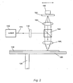
- FIG. 2 is another embodiment of the invention Lichtabtastvorraum shown.
- a light emitting device 110 e.g. a laser generates an excitation light beam 111, which refers to a schematically illustrated beam expansion optics 115 for Expansion of the excitation light beam hits.
- the beam expanding optics 115 may simultaneously contain a spatial filter to improve the beam quality.
- a dichroic beam splitter 164 the Exciting light almost completely at a right angle towards a sample 122 reflected.
- a focusing lens 165 which focuses the excitation light to a small spot on the sample.
- the sample 122 is again on a turntable 120 as in the previous embodiment removably mounted, which is rotatably supported via a rotation axis 121.
- the focusing optics are located first 165 followed by the dichroic beamsplitter 164 designed so that is the fluorescent light different in wavelength from the excitation light is almost completely transmitted to a detection optics 163, the fluorescent light focused on a pinhole 161, behind which a detector 162 is arranged.
- Embodiments may include a blocking filter for suppressing stray light from the Be provided light emission device in front of the respective detectors.
- a blocking filter for suppressing stray light from the Be provided light emission device in front of the respective detectors.
- the Barrier filter and the pinhole (which, of course, before the detectors 31 and 41 the embodiment shown in Fig. 1 is providable) is a strong suppression of achieved scattered excitation light and significantly improves the signal-to-noise ratio.
- the focusing lens 165 is combined with the beam splitter 164, the detection lens 163, the pinhole 161 and the detector 162 along the optical axis of the excitation light beam 111 between Light generating device and beam splitter displaced.
- an emission filter could also be used to match the wavelength to select the emission light.
- the light emitting device and / or the detection unit (s) could be used to arrange fixed and the light via flexible optical fibers to couple to the slidable focusing optics.
- the beam splitter could be omitted.
- Such Use of optical fibers in the embodiment shown in Fig. 1 allows a fixed arrangement of the detectors 31 and 41 with respect to the sliding movement of the Focusing lens, with a flexible connection between the detectors and the Focusing optics would be made by means of optical fibers.
- Figs. 1 and 2 would also be an arrangement conceivable for measurement in transmission.
- the beam splitter cube would respectively omitted and the detection units on the opposite side of the excitation the sample and the sample holder which is transparent in this case.
- the proof optics would then be with the linear movement of the or the excitation light beam coupled accordingly on the sample 22.
- the sample is applied to a carrier by means of a microspot application method, which is detachably mounted on the sample holder.
- the carrier can be a circular Be disc or have any other flat shape.
- the carrier is subjected to microdosing techniques, e.g. using a microdroppiezo technology, used. This makes it possible to spot single spot samples in the range of typically Apply 30 to 100 microns in diameter.
- the invention provides the significant advantage that the positioning of the scanning light beam on the sample due to the rotational movement or the linear movement is more controllable than by means of tilting the tilting mirror according to the prior Technique in which a gain of a positional tolerance as a mirror galvanometer occurred.
- the sampling time can be significant be shortened, wherein the rigid connection of the imaging and detection optics leads to an improvement of the positioning.
- the confocal arranged in front of the detectors Aperture diaphragms prevent the crosstalk of the two detectors assigned Channels and suppress stray light from the environment of the excitation light spot, causing the signal-to-noise ratio is improved.
- the possibility of multiple light emission devices and using different filters increases the flexibility of the system.
Abstract
Description
Die vorliegende Erfindung betrifft eine Lichtabtastvorrichtung zur Anregung und Detektion von Sekundärlicht, insbesondere von Fluoreszenzlicht, von einer Probe mit einer Lichtemissionsvorrichtung zur Aussendung von Anregungslicht mit einer für eine Sekundärlichtanregung auf oder in der Probe geeigneten Wellenlänge, einer Fokussierungsoptik zur Fokussierung des Anregungslichts auf die Probe, einer Probenhalterungsvorrichtung zur lösbaren Halterung der Probe, einer Nachweiseinheit mit einer Erfassungsoptik für das bei Anregung von der Probe emittierte Sekundärlicht und mit einer Detektorvorrichtung zur Umwandlung des Sekundärlichts in elektrische Signale.The present invention relates to a light scanning device for excitation and detection of secondary light, in particular fluorescent light, from a sample with a light emission device to emit excitation light with one for secondary light excitation on or in the sample suitable wavelength, a focusing optics for focusing of the excitation light on the sample, a sample holding device for releasable Holder of the sample, a detection unit with detection optics for the excitation secondary light emitted from the sample and having a detector device for conversion of the secondary light into electrical signals.
Derartige Lichtabtastvorrichtungen werden beispielsweise für molekularbiologische oder gentechnische Untersuchungen verwendet. Dabei wird eine Vielzahl von zu untersuchenden Stoffen feldartig auf einem Träger aufgebracht und mit einem fluoreszierenden Markierungsstoff vorübergehend in Kontakt gebracht. Diejenigen zu untersuchenden Stoffe, die eine Affinität zum Markierungsstoff aufweisen, binden den Markierungsstoff an sich und können folglich zur Emission von Fluoreszenzlicht angeregt werden. Durch die Anregbarkeit der Fluoreszenz wird somit die Eigenschaft des zu untersuchenden Stoffs, den Markierungsstoff an sich zu binden, sichtbar, wodurch Rückschlüsse auf die Art des Probenstoffs gezogen werden können.Such light scanning devices are used, for example, for molecular biological or used genetic engineering studies. It will be a variety of to be examined Substances are applied in a field-like manner on a support and with a fluorescent marker temporarily brought into contact. Those substances to be investigated which have an affinity for the tag, bind the tag itself and can thus be excited to emit fluorescent light. By the excitability Fluorescence thus becomes the property of the substance under investigation, the marker to bind to itself, visible, giving conclusions about the nature of the sample material can be pulled.
Bei mikrobiologischen oder gentechnischen Untersuchungen werden große Felder solcher mit Fluoreszenzstoffen markierter Stoffe mit Anregungslicht sequentiell abgetastet. Bei bisher bekannten Vorrichtungen erfolgte die Abtastung des die Probenstoffe haltenden Trägers mittels zweier im optischen Weg des Anregungslichts vorhandener Kippspiegel, die zwei zueinander senkrechte Drehachsen aufweisen. Wenn der Abtastlichtstrahl auf eine Stelle mit einer markierten und somit fluoreszierenden Probensubstanz trifft, wird Sekundärlicht ausgesendet, das von einer Nachweiseinheit mit einer Erfassungsoptik und einer Detektorvorrichtung erfasst und in elektrische Signale umgewandelt wird.In microbiological or genetic engineering studies, large fields become such sequentially scanned fluorescently labeled substances with excitation light. At so far known devices was the sampling of the samples holding the carrier by means of two existing in the optical path of the excitation light tilting mirror, the have two mutually perpendicular axes of rotation. When the scanning light beam on a Spot with a labeled and thus fluorescent sample substance hits, becomes secondary light emitted by a detection unit with a detection optics and a Detector device is detected and converted into electrical signals.
Bei derartigen Vorrichtungen ist jedoch die Drehung der Kippspiegel zur Abtastung toleranzbehaftet, was aufgrund des langen Strahlwegs zu großen Ungenauigkeiten in der Ortsauflösung der Abtastung führt. Weiter ist es bei einer "Pre-Objective-Scanning"-Anordnung der Fokussierungsoptik (d.h. zwischen der Abtasteinheit und der Probe) notwendig, dass diese einen großen Durchmesser aufweist, um das durch die Abtastspiegel von der optischen Achse abgelenkte Lichtstrahlenbündel in die Probenebene abzubilden. Bei solchen Objektiven mit einem großen Durchmesser ist jedoch eine Korrektur für große Bildwinkel und eine gute Bildfeldebnung sehr aufwendig und folglich mit erhöhten Kosten verbunden.In such devices, however, the rotation of the tilting mirror is sensitive to the scanning, which due to the long beam path to large inaccuracies in the Spatial resolution of the scan leads. Next is a "pre-objective scanning" arrangement the focusing optics (i.e., between the scanning unit and the sample), that this has a large diameter to the by the scanning mirror of the Imaged deflected light beam in the sample plane optical axis. In such However, lenses with a large diameter is a correction for large image angles and a good Bildfeldebnung very expensive and therefore associated with increased costs.
Es ist daher eine Aufgabe der vorliegenden Erfindung, eine Lichtabtastvorrichtung der eingangs genannten Art zu schaffen, mit der eine verbesserte Ortsauflösung bei vereinfachtem optischen Aufbau möglich ist.It is therefore an object of the present invention to provide a light scanning apparatus of the beginning mentioned type, with the improved spatial resolution in a simplified optical structure is possible.
Erfindungsgemäß wird diese Aufgabe gelöst durch eine Lichtabtastvorrichtung der eingangs genannten Art, die sich dadurch auszeichnet, dass die Probenhalterungsvorrichtung drehbar ist zur Drehung der Probe relativ zu dem Anregungslicht derart, dass unterschiedliche Teilgebiete der Probe mit dem Anregungslicht zur Aussendung von Sekundärlicht anregbar sind.According to the invention, this object is achieved by a light scanning device of the beginning mentioned type, which is characterized in that the sample holding device is rotatable to rotate the sample relative to the excitation light such that different Subareas of the sample with the excitation light for the emission of secondary light excitable are.
In einer weiteren erfindungsgemäßen Lösung dieser Aufgabe zeichnet sich die eingangs genannte Lichtabtastvorrichtung dadurch aus, dass die Fokussierungsoptik drehbar gehaltert ist zur Führung des Anregungslichts entlang eines Kreisbogens auf der Probe.In a further inventive solution to this problem, the beginning is called Lichtabtastvorrichtung characterized in that the focusing optics rotatably supported is to guide the excitation light along a circular arc on the sample.
Gemäß diesen beiden Lösungen wird das bisher bekannte Abtastsystem unter Verwendung von Kippspiegeln ersetzt durch eine mechanische Drehung entweder der Probe oder des Abtastlichtstrahls, wodurch jeweils ein Kreisbogen auf der Probenfläche abgetastet wird. Eine gemäß dem Galvanometerprinzip auftretende Verstärkung von Ungenauigkeiten bzw. Toleranzen bei der Verdrehung der Kippspiegel in den bisher bekannten Abtastvorrichtungen, die zu relativ großen Ungenauigkeiten in den Lagekoordinaten des Abtaststrahls auf der Probe führen, ist in der erfindungsgemäßen Vorrichtung ausgeschlossen, da die Strahlachse gegenüber der Probenfläche nicht verkippt wird. Somit können durch die erfindungsgemäßen Vorrichtungen hohe Ortsauflösungen von bis zu 2 µm, z.B. bei Verwendung einer geeigneten Laserdiode als Lichtemissionsvorrichtung, erzielt werden. Außerdem kann die Fokussierungsoptik zur Fokussierung des Anregungslichts auf ein Teilgebiet der Probe aus einem relativ kostengünstigen Objektiv mit kleinem Durchmesser und einem kleinen korrigierten Feldbereich bestehen. Dadurch lassen sich hohe Kosteneinsparungen bei der erfindungsgemäßen Vorrichtung durch Verwendung einer einfachen und billigen Fokussierungsoptik und den Wegfall der aufwendigen Halterungen und Ansteuerungen für die Kippspiegel erzielen.According to these two solutions, the previously known scanning system is used tilting mirrors replaced by a mechanical rotation of either the sample or the Scanning light beam, whereby in each case a circular arc is scanned on the sample surface. An increase of inaccuracies or inaccuracies occurring according to the galvanometer principle Tolerances in the rotation of the tilting mirror in the previously known scanning devices, the relatively large inaccuracies in the position coordinates of the scanning on lead the sample is excluded in the device according to the invention, since the beam axis is not tilted relative to the sample surface. Thus, by the inventive Devices high spatial resolutions of up to 2 μm, e.g. when using a suitable laser diode as a light emitting device can be achieved. In addition, the Focusing optics for focusing the excitation light on a subregion of the sample a relatively inexpensive lens with a small diameter and a small corrected Field area exist. This allows high cost savings in the inventive Device by using a simple and cheap focusing optics and the elimination of the costly brackets and controls for the tilting mirror achieve.
In einer vorteilhaften Weiterbildung der Erfindung ist die Fokussierungsoptik radial bezüglich der Drehachse der Probenhalterung verschiebbar bzw. die Probenhalterung in radialer Richtung bezüglich der optischen Achse der Fokussierungsoptik verschiebbar. Dadurch wird eine zweidimensionale Ortsauflösung mittels einer einfachen mechanischen Bewegung der Fokussierungsoptik bzw. des Probenhalters ohne Veränderung des Winkels der Strahlachse relativ zur Probenoberfläche erzielt. Daher wird gemäß dieser vorteilhaften Weiterbildung auch in der zweiten Dimension die sehr gute Ortsauflösung erreicht. Auch in dieser Ausführungsform ist das zuvor erwähnte kostengünstige Objektiv mit geringem Durchmesser und geringem Aufwand in der Bildfeldkorrektur verwendbar.In an advantageous embodiment of the invention, the focusing optics is radially with respect the axis of rotation of the sample holder displaceable or the sample holder in radial Direction displaceable with respect to the optical axis of the focusing optics. Thereby becomes a two-dimensional spatial resolution by means of a simple mechanical movement the focusing optics or the sample holder without changing the angle of the Beam axis achieved relative to the sample surface. Therefore, according to this advantageous Training also achieved in the second dimension, the very good spatial resolution. Also in This embodiment is the aforementioned low-cost low-power lens Diameter and little effort in the field correction can be used.
Gemäß einer weiteren vorteilhaften Weiterbildung sind zwei oder mehrere jeweils einander zugeordnete Paare der Fokussierungsoptik und der Nachweiseinheit vorgesehen. Dadurch lässt sich die Abtastzeit insbesondere bei Verwendung großer Proben und hoher Auflösung beträchtlich verringem. Bei Verwendung von zwei Paaren aus Fokussierungsoptik und Nachweiseinheit wird die Abtastzeit der Probenfläche halbiert. Dabei ist es bevorzugt, dass die beiden Paare aus Fokussierungsoptik und Nachweiseinheit einen Abstand ihrer optischen Wege aufweisen, der gleich dem halben Radius der Gesamtabtastfläche ist. Insbesondere ist es vorteilhaft, wenn die Paare der Fokussierungsoptik und der Nachweiseinheit mechanisch miteinander gekoppelt sind. In diesem Fall werden durch die mechanische Kopplung Stellelemente zur radialen Verschiebung der Fokussierungsoptik eingespart, wodurch wiederum die Kosten der erfindungsgemäßen Lichtabtastvorrichtung verringert werden, und andererseits wird durch die starre mechanische Verbindung eine genauere Positionierung gewährleistet.According to a further advantageous development, two or more are each each other associated pairs of the focusing optics and the detection unit provided. Thereby the sampling time can be especially when using large samples and high resolution considerably reduced. When using two pairs of focusing optics and Detection unit is halved the sampling time of the sample area. It is preferred that the two pairs of focusing optics and detection unit a distance of their optical Have paths that is equal to half the radius of the Gesamtabtastfläche. Especially it is advantageous if the pairs of the focusing optics and the detection unit mechanically coupled together. In this case, by the mechanical Coupling control elements for radial displacement of the focusing optics saved, thereby again the costs of the light scanning device according to the invention are reduced, and on the other hand, the rigid mechanical connection makes a more accurate positioning guaranteed.
Bei der gleichzeitigen Verwendung mehrerer Detektoren ist es vorteilhaft, Lochblenden jeweils in einer Abbildungsebene einer Erfassungsoptik vor der entsprechenden Detektorvorrichtung vorzusehen. Dadurch kann ein Übersprechen zwischen den einzelnen Detektoren und eine Aufnahme von Streulicht aus der Umgebung des Anregungslichtflecks verhindert werden. With the simultaneous use of multiple detectors, it is advantageous to pinhole each in an imaging plane of a detection optics in front of the corresponding detector device provided. This can cause crosstalk between the individual detectors and prevents the recording of stray light from the vicinity of the excitation light spot become.
Schließlich können in der erfindungsgemäßen Lichtabtastvorrichtung mehrere Lichtquellen mit verschiedenen Emissionslichtwellenlängen und/oder Farbfilter unterschiedlicher Transmissionswellenlänge vor den einzelnen Detektorvorrichtungen vorgesehen werden, was die Flexibilität und Vielseitigkeit des Systems erhöht.Finally, in the light scanning device according to the invention, a plurality of light sources with different emission light wavelengths and / or color filters of different transmission wavelengths be provided before the individual detector devices, what the Increased flexibility and versatility of the system.
Gemäß einem ersten Aspekt der Erfindung wird eine Lichtabtastvorrichtung zur Anregung und Detektion von Sekundärlicht, insbesondere von Fluoreszenzlicht, auf einer Probe bereitgestellt. Die Lichtabtastvorrichtung umfasst eine Lichtemissionsvorrichtung zur Aussendung von Anregungslicht mit einer für eine Sekundärlichtanregung auf oder in der Probe geeigneten Wellenlänge, eine Fokussierungsoptik zur Fokussierung des Anregungslichts auf ein Teilgebiet der Probe, eine Probenhalterungsvorrichtung zur lösbaren Halterung der Probe und eine Nachweiseinheit mit einer Erfassungsoptik für das bei Anregung von der Probe emittierte Sekundärlicht und mit einer Detektorvorrichtung zur Umwandlung des erfassten und abgebildeten Sekundärlichts in elektrische Signale. Die Probenhalterungsvorrichtung ist drehbar zur Drehung der Probe relativ zu dem Anregungslicht derart, dass unterschiedliche Teilgebiete der Probe mit dem Anregungslicht zur Aussendung von Sekundärlicht anregbar sind.According to a first aspect of the invention, a light scanning device for exciting and detection of secondary light, in particular fluorescent light, on one Sample provided. The light scanning device comprises a light emitting device for emitting excitation light with one for a secondary light excitation on or in the sample of suitable wavelength, a focusing optics for focusing the excitation light to a portion of the sample, a sample holding device for releasable Holder of the sample and a detection unit with a detection optics for Excitation of the sample emitted secondary light and with a detector device for Conversion of the detected and imaged secondary light into electrical signals. The Sample holding device is rotatable for rotation of the sample relative to the excitation light such that different subregions of the sample with the excitation light to the emission of secondary light are excitable.
Gemäß einem zweiten Aspekt der Erfindung wird eine Lichtabtastvorrichtung zur Anregung und Detektion von Sekundärlicht, insbesondere von Fluoreszenzlicht, auf einer Probe bereitgestellt. Die Lichtabtastvorrichtung umfasst eine Lichtemissionsvorrichtung zur Aussendung von Anregungslicht mit einer für eine Sekundärlichtanregung auf oder in der Probe geeigneten Wellenlänge, eine Fokussierungsoptik zur Fokussierung des Anregungslichts auf ein Teilgebiet der Probe, eine Probenhalterungsvorrichtung zur lösbaren Halterung der Probe, eine Nachweiseinheit mit einer Erfassungsoptik für das bei Anregung von der Probe emittierte Sekundärlicht und mit einer Detektorvorrichtung zur Umwandlung des erfassten und abgebildeten Sekundärlichts in elektrische Signale. Die Fokussierungsoptik ist drehbar gehaltert zur Führung des Anregungslichts entlang eines Kreisbogens auf der Probe.According to a second aspect of the invention, a light scanning device for exciting and detection of secondary light, in particular fluorescent light, on one Sample provided. The light scanning device comprises a light emitting device for emitting excitation light with one for a secondary light excitation on or in the sample of suitable wavelength, a focusing optics for focusing the excitation light to a portion of the sample, a sample holding device for releasable Holder of the sample, a detection unit with a detection optics for that when excited emitted from the sample secondary light and with a detector device for Conversion of the detected and imaged secondary light into electrical signals. The Focusing optics are rotatably supported to guide the excitation light along a Arc on the sample.
Gemäß einer Ausführungsform des ersten Aspektes der Erfindung ist die Fokussierungsoptik radial bezüglich einer Drehachse der Probenhalterungsvorrichtung verschiebbar. According to an embodiment of the first aspect of the invention, the focusing optics displaceable radially with respect to a rotation axis of the sample-holding device.
Gemäß einer Ausführungsform des zweiten Aspektes der Erfindung ist die Probenhalterung in radialer Richtung bezüglich einer Drehachse der Fokussierungsoptik verschiebbar.According to an embodiment of the second aspect of the invention, the sample holder is displaceable in the radial direction with respect to a rotational axis of the focusing optics.
Gemäß einer weiteren Ausführungsform der vorstehenden Aspekte sind die Nachweiseinheit und die Fokussierungsoptik zusammengekoppelt und weisen wenigstens teilweise einen gemeinsamen optischen Weg auf.According to another embodiment of the above aspects, the detection unit and the focusing optics coupled together and at least partially a common optical path.
Gemäß einer weiteren Ausführungsform des zweiten Aspektes weist die Fokussierungsoptik und die Erfassungsoptik der Nachweiseinheit einen gemeinsamen Strahlteiler auf, um die optischen Wege des Anregungslichts und des Sekundärlichts zu vereinen bzw. zu trennen.According to a further embodiment of the second aspect, the focusing optics and the detection optics of the detection unit have a common beam splitter, to combine the optical paths of the excitation light and the secondary light or to separate.
Gemäß einer weiteren Ausführungsform des zweiten Aspektes ist der Strahlteiler ein dichroitischer Strahlteiler, der entweder das Anregungslicht oder das Sekundärlicht reflektiert und das andere Licht im wesentlichen transmittiert.According to a further embodiment of the second aspect, the beam splitter is a dichroic beam splitter that reflects either the excitation light or the secondary light and the other light is substantially transmitted.
Gemäß einer weiteren Ausführungsform des zweiten Aspektes reflektiert und transmittiert der Strahlteiler das auf ihn einfallende Licht in einem Verhältnis von 50:50.Reflected and transmitted according to another embodiment of the second aspect the beam splitter the light incident on him in a ratio of 50:50.
Gemäß einer weiteren Ausführungsform der vorstehenden Aspekte der Erfindung sind wenigstens zwei jeweils einander zugeordnete Paare der Fokussierungsoptik und der Nachweiseinheit vorgesehen.According to another embodiment of the above aspects of the invention at least two mutually associated pairs of the focusing optics and the Detection unit provided.
Gemäß einer weiteren Ausführungsform der vorstehenden Aspekte der Erfindung sind die Paare der Fokussierungsoptik und der Nachweiseinheit mechanisch miteinander gekoppelt.According to another embodiment of the above aspects of the invention the pair of focusing optics and the detection unit mechanically coupled together.
Gemäß einer weiteren Ausführungsform der vorstehenden Aspekte der Erfindung ist vor der Detektorvorrichtung eine Lochblende in einer Abbildungsebene der Erfassungsoptik für das Sekundärlicht vorgesehen. According to a further embodiment of the above aspects of the invention is present the detector device, a pinhole in an imaging plane of the detection optics intended for the secondary light.
Gemäß einer weiteren Ausführungsform der vorstehenden Aspekte der Erfindung ist ein Sperrfilter zur Unterdrückung des Anregungslichts vor der Detektorvorrichtung vorgesehen.According to a further embodiment of the above aspects of the invention is a Blocking filter for suppressing the excitation light provided in front of the detector device.
Gemäß einer weiteren Ausführungsform der vorstehenden Aspekte der Erfindung sind die Detektorvorrichtung und/oder die Lichtemissionsvorrichtung fixiert vorgesehen.According to another embodiment of the above aspects of the invention the detector device and / or the light emission device fixedly provided.
Gemäß einer weiteren Ausführungsform der vorstehenden Aspekte der Erfindung sind die Detektorvorrichtung und/oder die Lichtemissionsvorrichtung mit der Erfassungsoptik bzw. der Fokussierungsoptik zur Lichtübertragung über Lichtleitfasern gekoppelt.According to another embodiment of the above aspects of the invention the detector device and / or the light emission device with the detection optics or the focusing optics coupled to the light transmission via optical fibers.
Gemäß einer weiteren Ausführungsform der vorstehenden Aspekte der Erfindung ist ein Farbfilter zur Transmission einer bestimmten Wellenlänge des Sekundärlichts vor der Detektorvorrichtung vorgesehen.According to a further embodiment of the above aspects of the invention is a Color filter for transmitting a specific wavelength of the secondary light before Detector device provided.
Gemäß einer weiteren Ausführungsform der vorstehenden Aspekte der Erfindung umfasst
die Lichtemissionsvorrichtung eine Vielzahl von Laserdioden mit jeweils unterschiedlicher
Ausgangswellenlänge.
Weitere vorteilhafte Ausführungsformen gehen aus den Unteransprüchen hervor.According to another embodiment of the above aspects of the invention, the light emitting device comprises a plurality of laser diodes each having a different output wavelength.
Further advantageous embodiments will become apparent from the dependent claims.
Nachfolgend wird die vorliegende Erfindung beispielhaft anhand eines bevorzugten Ausführungsbeispiels näher erläutert und beschrieben. In den begleitenden Zeichnungen zeigen:
- Fig. 1
- eine schematische Ansicht eines Aufbaus einer erfindungsgemäßen Ausführungsform; und
- Fig. 2
- eine schematische Darstellung einer weiteren Ausführungsform der vorliegenden Erfindung.
- Fig. 1
- a schematic view of a structure of an embodiment of the invention; and
- Fig. 2
- a schematic representation of another embodiment of the present invention.
In Fig. 1 ist eine Ausführungsform der erfindungsgemäßen Lichtabtastvorrichtung schematisch
dargestellt. Eine Lichtemissionsvorrichtung 10, bei der es sich z.B. um einen Laser
handelt, emittiert einen Lichtstrahl 11, der auf eine erste Einheit 30 mit einer Fokussierungsoptik
für den Lichtstrahl und einer Erfassungsoptik für das Sekundärlicht trifft. Die
erste Einheit 30 umfasst einen Trägerkörper 35 zur Halterung eines Strahlteilerwürfels 33,
eines Fokussierungsobjektivs 34 zur Fokussierung des von der Lichtemissionsvorrichtung
10 emittierten Lichts auf die Probe, eines Erfassungsobjektivs 32 zur Erfassung und
Sammlung von Sekundärlicht und eines Detektors 31. Der Trägerkörper 35 besitzt entlang
des Ausbreitungswegs des Emissionslichtstrahlenbündels 11 Ausnehmungen, die einen
Durchgang des Lichtstrahlenbündels 11 erlauben. Im optischen Weg des Lichtstrahlenbündels
11 ist der Strahlteiler 33 so angeordnet, dass das Strahlenbündel 11 teilweise im wesentlichen
senkrecht reflektiert wird und anschließend entlang einer durch das Fokussierungsobjektiv
34 verlaufenden optischen Achse 12 verläuft. Der durch den Strahlteiler 33
transmittierte Teil des Strahlenbündels verlässt an einer entsprechenden zweiten Ausnehmung
den Trägerkörper 35 und trifft auf eine zweite Einheit 40, die im wesentlichen zur
ersten Einheit 30 identisch aufgebaut ist.In Fig. 1, an embodiment of the light scanning device according to the invention is schematic
shown. A
Die zweite Einheit 40 umfasst somit einen Detektor 41, ein Erfassungsobjektiv 42 zur Erfassung
und Sammlung des Sekundärlichts, einen Strahlteiler 43 und eine Fokussierungsoptik
44, die sämtlich in einem Trägerkörper 45 gehaltert sind. Der Trägerkörper 45 weist
wieder geeignet angeordnete Ausnehmungen zum Eintritt und Austritt des von der
Lichtemissionsvorrichtung 10 erzeugten, sich geradlinig ausbreitenden Strahlenbündels 11
auf.The
In der gezeigten Ausführungsform sind die beiden Einheiten 30 und 40 mittels einer starren
Verbindung 51 mechanisch gekoppelt. Wie durch die horizontalen Pfeile angezeigt ist, sind
die Einheiten 30 und 40 gemeinsam entlang der Ausbreitungsrichtung des nicht abgelenkten,
von der Emissionsvorrichtung 10 emittierten Strahlenbündels 11 verschiebbar.In the embodiment shown, the two
Gegenüberliegend zu den beiden Fokussierungsobjektiven 34 und 44 ist eine Probe 22
angeordnet, die auf einer Probenhalterung 20 lösbar gehaltert ist. Die Probenhalterung 20
ist in der gezeigten Ausführungsform ein an einer Drehachse 21 gehalterter Drehteller. Zur
Halterung der Probe 22 auf dem Drehteller 20 können nicht gezeigte Aufspannelemente
oder Vakuumansaugleitungen vorhanden sein, wobei jedoch meist die normale Reibung
der Probe auf der Unterlage genügt.Opposite the two focusing
In der in Fig. 1 gezeigten Ausführungsform ist der Abstand zwischen den Einheiten 30 und
40 der halbe Radius des auf der Probe 22 abzutastenden Gebiets. In the embodiment shown in Fig. 1, the distance between the
Der optische Weg des von der Lichtemissionsvorrichtung 10 emittierten Lichtstrahlenbündels
11 verläuft zuerst im wesentlichen parallel zur Oberfläche der Probe 22 und wird jeweils
an den Strahlteilern 33 und 43 in eine Richtung im wesentlichen senkrecht zur Oberfläche
der Probe 22 abgelenkt, um das Anregungslicht über die Fokussierungsobjektive 34
und 44 auf zwei Stellen der Probenoberfläche zu fokussieren. Das bei Fluoreszenz von der
Probenoberfläche abgestrahlte Sekundärlicht geht in den oberen Halbraum (falls die Probenhalterung
20 absorbiert). Davon wird nur derjenige Teil für den Detektor genutzt, der
von der Optik 34, 32 bzw. 44, 42 aufgenommen werden kann. Nach Sammlung durch die
Fokussierungsobjektive 34 und 44 geht das Sekundärlicht zu den Strahlteilern 33 und 43
über. An den Strahlteilern 33 und 43 werden die zwischen der Probe 22 und den beiden
Strahlteilern für das Anregungslicht und das Sekundärlicht vereinten optischen Wege getrennt.
Ein Teil des Sekundärlichts wird jeweils an den Strahlteilern 33 und 43 in Richtung
der Lichtemissionsvorrichtung 10 reflektiert, während ein anderer Teil durch die Strahlteilerwürfel
durchgeht und auf die jeweiligen Erfassungsobjektive 32 und 42 trifft, die das Sekundärlicht
auf den entsprechenden Detektor 31 bzw. 41 abbilden.The optical path of the light beam emitted from the
Man kann einen polarisierenden Strahlteilerwürfel einsetzen, der ein polarisiertes Anregungslicht
mit hoher Reflektivität in Richtung der Proben reflektiert. Die fluoreszierenden
Moleküle sind statistisch ("random") verteilt und emittieren in alle Polarisationsrichtungen.
Daher wird in Richtung der Lichtemissionsvorrichtung 10 nur wenig reflektiert, während das
meiste Licht durch den Strahlteiler geht.You can use a polarizing beam splitter cube, which is a polarized excitation light
reflected with high reflectivity in the direction of the samples. The fluorescent
Molecules are randomly distributed and emit in all polarization directions.
Therefore, little reflection is given to the
In der gezeigten Ausführungsform bei Verwendung von zwei Einheiten 30 und 40 besitzen
die Strahlteiler beispielsweise ein Aufteilungsverhältnis von 50:50.In the embodiment shown when using two
In Fig. 2 ist eine weitere Ausführungsform der erfindungsgemäßen Lichtabtastvorrichtung
gezeigt. Eine Lichtemissionsvorrichtung 110, z.B. ein Laser, erzeugt ein Anregungslichtstrahlenbündel
111, das auf eine schematisch dargestellte Strahlaufweitungsoptik 115 zur
Aufweitung des Anregungslichtstrahlenbündels trifft. Die Strahlaufweitungsoptik 115 kann
gleichzeitig zur Verbesserung der Strahlqualität einen Raumfilter enthalten. Anschließend
folgt im optischen Weg des Anregungslichtstrahls ein dichroitischer Strahlteiler 164, der das
Anregungslicht nahezu vollständig unter einem rechten Winkel in Richtung auf eine Probe
122 reflektiert. Zwischen dem Strahlteiler und der Probe 122 ist ein Fokussierungsobjektiv
165 angeordnet, das das Anregungslicht auf einen kleinen Fleck auf der Probe fokussiert. In Fig. 2 is another embodiment of the invention Lichtabtastvorrichtung
shown. A
Die Probe 122 ist wieder wie in der vorherigen Ausführungsform auf einem Drehteller 120
lösbar angebracht, der über eine Drehachse 121 drehbar gehaltert ist.The
Im optischen Weg des von der Probe 122 emittierten Fluoreszenzlichts liegt zuerst die Fokussierungsoptik
165, auf die der dichroitische Strahlteiler 164 folgt, der so entworfen ist,
dass das sich in der Wellenlänge vom Anregungslicht unterscheidende Fluoreszenzlicht
nahezu vollständig transmittiert wird zu einer Erfassungsoptik 163, die das Fluoreszenzlicht
auf eine Lochblende 161 fokussiert, hinter der ein Detektor 162 angeordnet ist.In the optical path of the fluorescent light emitted by the
Zusätzlich zu den in den Figuren 1 und 2 gezeigten Elementen der oben beschriebenen
Ausführungsformen kann ein Sperrfilter zur Unterdrückung von Streulicht von der
Lichtemissionsvorrichtung vor den jeweiligen Detektoren vorgesehen sein. Durch das
Sperrfilter und die Lochblende (die selbstverständlich auch vor den Detektoren 31 und 41
der in Fig. 1 gezeigten Ausführungsform vorsehbar ist) wird eine starke Unterdrückung von
gestreutem Anregungslicht erzielt und das Signal-zu-Rauschverhältnis deutlich verbessert.
In der in Fig. 2 gezeigten Ausführungsform ist das Fokussierungsobjektiv 165 zusammen
mit den Strahlteiler 164, dem Erfassungsobjektiv 163, der Lochblende 161 und dem Detektor
162 entlang der optischen Achse des Anregungslichtstrahlenbündels 111 zwischen
Lichterzeugungsvorrichtung und Strahlteiler verschiebbar.In addition to the elements shown in Figures 1 and 2 of the above-described
Embodiments may include a blocking filter for suppressing stray light from the
Be provided light emission device in front of the respective detectors. By the
Barrier filter and the pinhole (which, of course, before the
An der Lochblende 161 könnte auch ein Emissionsfilter eingesetzt werden, um die Wellenlänge
des Emissionslichts zu selektionieren.At the
In den beiden gezeigten Ausführungsformen wäre es auch möglich, die Anordnung von Laser und Nachweisoptik unter entsprechender Umorientierung des Strahlteilers zu vertauschen. Weiter wäre es möglich, anstelle der Drehbewegung der Probenhalterung und der Linearbewegung der Fokussierungs- und Nachweiseinheit die Drehbewegung bei letzterer vorzusehen, und stattdessen die Probe linear verschiebbar anzuordnen, wodurch wiederum das gesamte Probengebiet abrasterbar wäre.In the two embodiments shown, it would also be possible to use the arrangement of Laser and detection optics with appropriate reorientation of the beam splitter to swap. It would also be possible, instead of the rotational movement of the sample holder and the Linear movement of the focusing and detection unit, the rotational movement in the latter provide, and instead to arrange the sample linearly displaceable, which in turn the entire sample area could be scanned.
Bei den gezeigten Ausführungsformen wäre es weiter möglich, die Lichtemissionsvorrichtung
und/oder die Nachweiseinheit(en) fixiert anzuordnen und das Licht über flexible Lichtleitfasern
an die verschiebbare Fokussierungsoptik zu koppeln. Bei Verwendung von Lichtleitfasem
zur Einkopplung des Anregungslichts und zur Übertragung des von der Probe
emittierten Fluoreszenzlichts zum Detektor könnte der Strahlteiler entfallen. Eine derartige
Verwendung von Lichtleitfasern bei der in Fig. 1 gezeigten Ausführungsform ermöglicht
eine fixierte Anordnung der Detektoren 31 und 41 bezüglich der Verschiebebewegung des
Fokussierungsobjektivs, wobei eine flexible Verbindung zwischen den Detektoren und der
Fokussierungsoptik mittels der Lichtleitfasern hergestellt würde.In the embodiments shown, it would further be possible to use the light emitting device
and / or the detection unit (s) to arrange fixed and the light via flexible optical fibers
to couple to the slidable focusing optics. When using Lichtleitfasem
for coupling the excitation light and for transferring it from the sample
emitted fluorescent light to the detector, the beam splitter could be omitted. Such
Use of optical fibers in the embodiment shown in Fig. 1 allows
a fixed arrangement of the
Bei Verwendung mehrerer Fokussierungs- und Nachweiseinheiten ist es auch möglich, unterschiedliche Wellenlängenfilter vor den jeweiligen Detektoren vorzusehen, wodurch verschiedene Fluorophore oder mehrere Wellenlängen des gleichen Fluoreszenzfarbstoffs simultan gemessen werden können. Andererseits kann man unterschiedliche Lichtemissionsvorrichtungen vorsehen, die jeweils über einen eigenen Strahlengang eingekoppelt werden und verschiedene Anregungswellenlängen zur Anregung verschiedener Fluoreszenzfarbstoffe aufweisen. Damit ist es ebenfalls möglich, die Probe bezüglich verschiedener Farbstoffe gleichzeitig zu vermessen.When using multiple focusing and detection units it is also possible provide different wavelength filter in front of the respective detectors, thereby different fluorophores or multiple wavelengths of the same fluorescent dye can be measured simultaneously. On the other hand, one can different light emission devices Provide, each coupled via its own beam path and different excitation wavelengths for excitation of different fluorescent dyes exhibit. Thus, it is also possible to sample the various To measure dyes simultaneously.
Anstatt den in Fig. 1 und 2 gezeigten reflektiven Anordnungen wäre auch eine Anordnung
zur Messung in Transmission denkbar. In diesem Fall würden die Strahlteilerwürfel jeweils
entfallen und die Nachweiseinheiten auf der der Anregungsseite gegenüberliegenden Seite
der Probe und des in diesem Fall transparenten Probenhalters angeordnet sein. Die Nachweisoptik
wäre dann mit der Linearbewegung des oder der Anregungslichtstrahlenbündel
auf der Probe 22 entsprechend gekoppelt.Instead of the reflective arrangements shown in Figs. 1 and 2 would also be an arrangement
conceivable for measurement in transmission. In this case, the beam splitter cube would respectively
omitted and the detection units on the opposite side of the excitation
the sample and the sample holder which is transparent in this case. The proof optics
would then be with the linear movement of the or the excitation light beam
coupled accordingly on the
Speziell bei Verwendung einer oder mehrerer Laserdioden als Lichtemissionsvorrichtung ist
die Verwendung einer Strahlformungsoptik, wie symbolisch mit Bezugszeichen 115 in Fig. 2
angezeigt, vorteilhaft.Especially when using one or more laser diodes as the light emitting device
the use of beam shaping optics, as symbolically represented by
Die Probe ist mittels eines Mikrospotauftragungsverfahrens auf einem Träger aufgebracht, der auf der Probenhalterung lösbar angebracht ist. Der Träger kann eine kreisrunde Scheibe sein oder auch eine beliebige andere flache Form besitzen. Zur Probenaufgabe auf den Träger werden Mikrodosiertechniken, z.B. unter Verwendung einer Mikrodroppiezotechnologie, verwendet. Damit ist es möglich, einzelne Spotproben im Bereich von typischerweise 30 bis 100 µm Durchmesser aufzutragen. The sample is applied to a carrier by means of a microspot application method, which is detachably mounted on the sample holder. The carrier can be a circular Be disc or have any other flat shape. For sample application the carrier is subjected to microdosing techniques, e.g. using a microdroppiezo technology, used. This makes it possible to spot single spot samples in the range of typically Apply 30 to 100 microns in diameter.
Die Erfindung schafft den wesentlichen Vorteil, dass die Positionierung des Abtastlichtstrahlenbündels auf der Probe aufgrund der Rotationsbewegung bzw. der Linearbewegung genauer steuerbar ist als mittels einer Verkippung der Kippspiegel gemäß dem Stand der Technik, bei denen eine Verstärkung einer Positionstoleranz wie bei einem Spiegelgalvanometer auftrat. Durch die Verwendung mehrerer Detektoren kann die Abtastzeit wesentlich verkürzt werden, wobei die starre Verbindung der Abbildungs- und Erfassungsoptiken zu einer Verbesserung der Positionierung führt. Die konfokal vor den Detektoren angeordneten Lochblenden verhindern das Übersprechen der den beiden Detektoren zugeordneten Kanäle und unterdrücken Streulicht aus der Umgebung des Anregungslichtspots, wodurch das Signal-zu-Rauschverhältnis verbessert wird. Die Möglichkeit, mehrere Lichtemissionsvorrichtungen und verschiedene Filter einzusetzen, erhöht die Flexibilität des Systems.The invention provides the significant advantage that the positioning of the scanning light beam on the sample due to the rotational movement or the linear movement is more controllable than by means of tilting the tilting mirror according to the prior Technique in which a gain of a positional tolerance as a mirror galvanometer occurred. By using multiple detectors, the sampling time can be significant be shortened, wherein the rigid connection of the imaging and detection optics leads to an improvement of the positioning. The confocal arranged in front of the detectors Aperture diaphragms prevent the crosstalk of the two detectors assigned Channels and suppress stray light from the environment of the excitation light spot, causing the signal-to-noise ratio is improved. The possibility of multiple light emission devices and using different filters increases the flexibility of the system.
Claims (4)
Applications Claiming Priority (3)
| Application Number | Priority Date | Filing Date | Title |
|---|---|---|---|
| DE19707226 | 1997-02-24 | ||
| DE19707226A DE19707226A1 (en) | 1997-02-24 | 1997-02-24 | Light scanner |
| EP97953740A EP0961929B1 (en) | 1997-02-24 | 1997-12-04 | Light-scanning device |
Related Parent Applications (1)
| Application Number | Title | Priority Date | Filing Date |
|---|---|---|---|
| EP97953740A Division EP0961929B1 (en) | 1997-02-24 | 1997-12-04 | Light-scanning device |
Publications (2)
| Publication Number | Publication Date |
|---|---|
| EP1610117A2 true EP1610117A2 (en) | 2005-12-28 |
| EP1610117A3 EP1610117A3 (en) | 2006-05-10 |
Family
ID=7821242
Family Applications (2)
| Application Number | Title | Priority Date | Filing Date |
|---|---|---|---|
| EP97953740A Expired - Lifetime EP0961929B1 (en) | 1997-02-24 | 1997-12-04 | Light-scanning device |
| EP05020027A Withdrawn EP1610117A3 (en) | 1997-02-24 | 1997-12-04 | Light scanning device |
Family Applications Before (1)
| Application Number | Title | Priority Date | Filing Date |
|---|---|---|---|
| EP97953740A Expired - Lifetime EP0961929B1 (en) | 1997-02-24 | 1997-12-04 | Light-scanning device |
Country Status (6)
| Country | Link |
|---|---|
| US (1) | US6211989B1 (en) |
| EP (2) | EP0961929B1 (en) |
| JP (2) | JP3660691B2 (en) |
| AU (1) | AU5753998A (en) |
| DE (2) | DE19707226A1 (en) |
| WO (1) | WO1998038495A1 (en) |
Families Citing this family (67)
| Publication number | Priority date | Publication date | Assignee | Title |
|---|---|---|---|---|
| US5631734A (en) * | 1994-02-10 | 1997-05-20 | Affymetrix, Inc. | Method and apparatus for detection of fluorescently labeled materials |
| US6048734A (en) | 1995-09-15 | 2000-04-11 | The Regents Of The University Of Michigan | Thermal microvalves in a fluid flow method |
| DE19844713C2 (en) * | 1998-09-29 | 2001-09-20 | Gsf Forschungszentrum Umwelt | Fluorescence measuring device |
| JP2000121559A (en) * | 1998-10-14 | 2000-04-28 | Hitachi Denshi Ltd | Device for reading quantity of light of micro spot |
| JP3597729B2 (en) * | 1999-05-11 | 2004-12-08 | 日立ソフトウエアエンジニアリング株式会社 | Fluorescence metering method and fluorescence meter |
| US20050279949A1 (en) * | 1999-05-17 | 2005-12-22 | Applera Corporation | Temperature control for light-emitting diode stabilization |
| US7423750B2 (en) * | 2001-11-29 | 2008-09-09 | Applera Corporation | Configurations, systems, and methods for optical scanning with at least one first relative angular motion and at least one second angular motion or at least one linear motion |
| DE19959742A1 (en) * | 1999-12-10 | 2001-06-13 | Zeiss Carl | System for compensating for changes in direction and position of a light generated by a laser |
| US6912076B2 (en) * | 2000-03-17 | 2005-06-28 | Accu-Sort Systems, Inc. | Coplanar camera scanning system |
| US6563581B1 (en) * | 2000-07-14 | 2003-05-13 | Applera Corporation | Scanning system and method for scanning a plurality of samples |
| US6603546B1 (en) * | 2000-07-21 | 2003-08-05 | I.S.S. (Usa) Inc. | Rapid high throughput spectrometer and method |
| CA2418271A1 (en) * | 2000-08-03 | 2002-07-04 | Perlegen Sciences | High performance substrate scanning |
| US7062092B2 (en) | 2000-08-22 | 2006-06-13 | Affymetrix, Inc. | System, method, and computer software product for gain adjustment in biological microarray scanner |
| US6692700B2 (en) | 2001-02-14 | 2004-02-17 | Handylab, Inc. | Heat-reduction methods and systems related to microfluidic devices |
| US7829025B2 (en) | 2001-03-28 | 2010-11-09 | Venture Lending & Leasing Iv, Inc. | Systems and methods for thermal actuation of microfluidic devices |
| US8895311B1 (en) | 2001-03-28 | 2014-11-25 | Handylab, Inc. | Methods and systems for control of general purpose microfluidic devices |
| US7010391B2 (en) | 2001-03-28 | 2006-03-07 | Handylab, Inc. | Methods and systems for control of microfluidic devices |
| US7323140B2 (en) | 2001-03-28 | 2008-01-29 | Handylab, Inc. | Moving microdroplets in a microfluidic device |
| US6852287B2 (en) | 2001-09-12 | 2005-02-08 | Handylab, Inc. | Microfluidic devices having a reduced number of input and output connections |
| US6643015B2 (en) | 2001-04-26 | 2003-11-04 | Affymetrix, Inc. | System, method, and product for symmetrical filtering in scanning of biological materials |
| US6490533B2 (en) | 2001-04-26 | 2002-12-03 | Affymetrix, Inc. | System, method, and product for dynamic noise reduction in scanning of biological materials |
| US6650411B2 (en) | 2001-04-26 | 2003-11-18 | Affymetrix, Inc. | System, method, and product for pixel clocking in scanning of biological materials |
| DE10136863A1 (en) | 2001-07-28 | 2003-02-20 | Berthold Tech Gmbh & Co Kg | Device for the optional measurement of in particular luminescence and / or fluorescence radiation |
| CA2422224A1 (en) | 2002-03-15 | 2003-09-15 | Affymetrix, Inc. | System, method, and product for scanning of biological materials |
| DE20214868U1 (en) * | 2002-07-31 | 2003-03-13 | Tecan Trading Ag Maennedorf | Device for measuring the lifetime of fluorescence from fluorophores in samples |
| US7148043B2 (en) | 2003-05-08 | 2006-12-12 | Bio-Rad Laboratories, Inc. | Systems and methods for fluorescence detection with a movable detection module |
| US7731906B2 (en) | 2003-07-31 | 2010-06-08 | Handylab, Inc. | Processing particle-containing samples |
| US7317415B2 (en) | 2003-08-08 | 2008-01-08 | Affymetrix, Inc. | System, method, and product for scanning of biological materials employing dual analog integrators |
| US8852862B2 (en) | 2004-05-03 | 2014-10-07 | Handylab, Inc. | Method for processing polynucleotide-containing samples |
| AU2005241080B2 (en) | 2004-05-03 | 2011-08-11 | Handylab, Inc. | Processing polynucleotide-containing samples |
| WO2006014494A2 (en) * | 2004-07-07 | 2006-02-09 | Corcoran Timothy C | Multiple-label fluorescence imaging using excitation-emission matrices |
| EP1787106A1 (en) * | 2004-09-10 | 2007-05-23 | Wallac Oy | Instrumentation and method adapted for optical measurement of an amplified luminescent proximity homogeneous assay |
| JP4577645B2 (en) * | 2004-09-30 | 2010-11-10 | 横河電機株式会社 | Screening equipment |
| US7507575B2 (en) * | 2005-04-01 | 2009-03-24 | 3M Innovative Properties Company | Multiplex fluorescence detection device having removable optical modules |
| US7709249B2 (en) * | 2005-04-01 | 2010-05-04 | 3M Innovative Properties Company | Multiplex fluorescence detection device having fiber bundle coupling multiple optical modules to a common detector |
| US8351026B2 (en) | 2005-04-22 | 2013-01-08 | Affymetrix, Inc. | Methods and devices for reading microarrays |
| US7754148B2 (en) | 2006-12-27 | 2010-07-13 | Progentech Limited | Instrument for cassette for sample preparation |
| US7727473B2 (en) | 2005-10-19 | 2010-06-01 | Progentech Limited | Cassette for sample preparation |
| WO2007091530A1 (en) | 2006-02-07 | 2007-08-16 | The Furukawa Electric Co., Ltd. | Photodetector and measurement object reader |
| US8088616B2 (en) * | 2006-03-24 | 2012-01-03 | Handylab, Inc. | Heater unit for microfluidic diagnostic system |
| JP5415253B2 (en) | 2006-03-24 | 2014-02-12 | ハンディラブ・インコーポレーテッド | Integrated system for processing microfluidic samples and methods of use thereof |
| US8883490B2 (en) | 2006-03-24 | 2014-11-11 | Handylab, Inc. | Fluorescence detector for microfluidic diagnostic system |
| US11806718B2 (en) | 2006-03-24 | 2023-11-07 | Handylab, Inc. | Fluorescence detector for microfluidic diagnostic system |
| US10900066B2 (en) | 2006-03-24 | 2021-01-26 | Handylab, Inc. | Microfluidic system for amplifying and detecting polynucleotides in parallel |
| US7998708B2 (en) | 2006-03-24 | 2011-08-16 | Handylab, Inc. | Microfluidic system for amplifying and detecting polynucleotides in parallel |
| US8009889B2 (en) | 2006-06-27 | 2011-08-30 | Affymetrix, Inc. | Feature intensity reconstruction of biological probe array |
| WO2008061165A2 (en) | 2006-11-14 | 2008-05-22 | Handylab, Inc. | Microfluidic cartridge and method of making same |
| AU2013205253B8 (en) * | 2007-07-13 | 2015-10-22 | Handylab, Inc. | Integrated apparatus for performing nucleic acid extraction and diagnostic testing on multiple biological samples |
| USD621060S1 (en) | 2008-07-14 | 2010-08-03 | Handylab, Inc. | Microfluidic cartridge |
| US8287820B2 (en) | 2007-07-13 | 2012-10-16 | Handylab, Inc. | Automated pipetting apparatus having a combined liquid pump and pipette head system |
| US8105783B2 (en) | 2007-07-13 | 2012-01-31 | Handylab, Inc. | Microfluidic cartridge |
| US8133671B2 (en) | 2007-07-13 | 2012-03-13 | Handylab, Inc. | Integrated apparatus for performing nucleic acid extraction and diagnostic testing on multiple biological samples |
| WO2009012185A1 (en) | 2007-07-13 | 2009-01-22 | Handylab, Inc. | Polynucleotide capture materials, and methods of using same |
| US8182763B2 (en) | 2007-07-13 | 2012-05-22 | Handylab, Inc. | Rack for sample tubes and reagent holders |
| US9186677B2 (en) | 2007-07-13 | 2015-11-17 | Handylab, Inc. | Integrated apparatus for performing nucleic acid extraction and diagnostic testing on multiple biological samples |
| US20090136385A1 (en) | 2007-07-13 | 2009-05-28 | Handylab, Inc. | Reagent Tube |
| US9618139B2 (en) * | 2007-07-13 | 2017-04-11 | Handylab, Inc. | Integrated heater and magnetic separator |
| USD618820S1 (en) | 2008-07-11 | 2010-06-29 | Handylab, Inc. | Reagent holder |
| USD787087S1 (en) | 2008-07-14 | 2017-05-16 | Handylab, Inc. | Housing |
| US9767342B2 (en) | 2009-05-22 | 2017-09-19 | Affymetrix, Inc. | Methods and devices for reading microarrays |
| EP2539426B1 (en) * | 2010-02-23 | 2016-11-09 | Luminex Corporation | Apparatus for integrated sample preparation, reaction and detection |
| CN106190806B (en) | 2011-04-15 | 2018-11-06 | 贝克顿·迪金森公司 | Scan real-time microfluid thermal cycler and the method for synchronous thermal cycle and scanning optical detection |
| CA2834790C (en) | 2011-05-04 | 2019-04-09 | Luminex Corporation | Apparatus and methods for integrated sample preparation, reaction and detection |
| KR102121853B1 (en) | 2011-09-30 | 2020-06-12 | 벡톤 디킨슨 앤드 컴퍼니 | Unitized reagent strip |
| USD692162S1 (en) | 2011-09-30 | 2013-10-22 | Becton, Dickinson And Company | Single piece reagent holder |
| CN104040238B (en) | 2011-11-04 | 2017-06-27 | 汉迪拉布公司 | Polynucleotides sample preparation apparatus |
| CN107881219B (en) | 2012-02-03 | 2021-09-10 | 贝克顿·迪金森公司 | External file for molecular diagnostic test assignment and compatibility determination between tests |
Citations (7)
| Publication number | Priority date | Publication date | Assignee | Title |
|---|---|---|---|---|
| US5091652A (en) * | 1990-01-12 | 1992-02-25 | The Regents Of The University Of California | Laser excited confocal microscope fluorescence scanner and method |
| EP0504432A1 (en) * | 1990-10-09 | 1992-09-23 | Idemitsu Petrochemical Co. Ltd. | Method of immunological quantitative analysis |
| US5223718A (en) * | 1992-08-10 | 1993-06-29 | Alcor, Inc. | Method and apparatus for quantifying thermal oxidation tester tube deposits |
| US5459325A (en) * | 1994-07-19 | 1995-10-17 | Molecular Dynamics, Inc. | High-speed fluorescence scanner |
| WO1996009548A1 (en) * | 1994-09-21 | 1996-03-28 | The University Court Of The University Of Glasgow | Apparatus and method for carrying out analysis of samples |
| US5537247A (en) * | 1994-03-15 | 1996-07-16 | Technical Instrument Company | Single aperture confocal imaging system |
| EP0753779A2 (en) * | 1995-07-13 | 1997-01-15 | Yokogawa Electric Corporation | Confocal microscope |
Family Cites Families (4)
| Publication number | Priority date | Publication date | Assignee | Title |
|---|---|---|---|---|
| US3918812A (en) * | 1973-05-07 | 1975-11-11 | Us Energy | Diagnoses of disease states by fluorescent measurements utilizing scanning laser beams |
| US4405993A (en) * | 1981-01-02 | 1983-09-20 | Hewlett-Packard Company | Liquid crystal disc memory system |
| US4626684A (en) * | 1983-07-13 | 1986-12-02 | Landa Isaac J | Rapid and automatic fluorescence immunoassay analyzer for multiple micro-samples |
| US5022757A (en) * | 1989-01-23 | 1991-06-11 | Modell Mark D | Heterodyne system and method for sensing a target substance |
-
1997
- 1997-02-24 DE DE19707226A patent/DE19707226A1/en not_active Withdrawn
- 1997-12-04 AU AU57539/98A patent/AU5753998A/en not_active Abandoned
- 1997-12-04 EP EP97953740A patent/EP0961929B1/en not_active Expired - Lifetime
- 1997-12-04 WO PCT/EP1997/006793 patent/WO1998038495A1/en active IP Right Grant
- 1997-12-04 EP EP05020027A patent/EP1610117A3/en not_active Withdrawn
- 1997-12-04 JP JP53720398A patent/JP3660691B2/en not_active Expired - Fee Related
- 1997-12-04 US US09/367,949 patent/US6211989B1/en not_active Expired - Lifetime
- 1997-12-04 DE DE59712623T patent/DE59712623D1/en not_active Expired - Lifetime
-
2005
- 2005-01-24 JP JP2005015926A patent/JP2005140796A/en active Pending
Patent Citations (7)
| Publication number | Priority date | Publication date | Assignee | Title |
|---|---|---|---|---|
| US5091652A (en) * | 1990-01-12 | 1992-02-25 | The Regents Of The University Of California | Laser excited confocal microscope fluorescence scanner and method |
| EP0504432A1 (en) * | 1990-10-09 | 1992-09-23 | Idemitsu Petrochemical Co. Ltd. | Method of immunological quantitative analysis |
| US5223718A (en) * | 1992-08-10 | 1993-06-29 | Alcor, Inc. | Method and apparatus for quantifying thermal oxidation tester tube deposits |
| US5537247A (en) * | 1994-03-15 | 1996-07-16 | Technical Instrument Company | Single aperture confocal imaging system |
| US5459325A (en) * | 1994-07-19 | 1995-10-17 | Molecular Dynamics, Inc. | High-speed fluorescence scanner |
| WO1996009548A1 (en) * | 1994-09-21 | 1996-03-28 | The University Court Of The University Of Glasgow | Apparatus and method for carrying out analysis of samples |
| EP0753779A2 (en) * | 1995-07-13 | 1997-01-15 | Yokogawa Electric Corporation | Confocal microscope |
Also Published As
| Publication number | Publication date |
|---|---|
| EP0961929B1 (en) | 2006-04-19 |
| JP3660691B2 (en) | 2005-06-15 |
| JP2005140796A (en) | 2005-06-02 |
| JP2000509826A (en) | 2000-08-02 |
| US6211989B1 (en) | 2001-04-03 |
| DE59712623D1 (en) | 2006-05-24 |
| EP0961929A1 (en) | 1999-12-08 |
| WO1998038495A1 (en) | 1998-09-03 |
| EP1610117A3 (en) | 2006-05-10 |
| AU5753998A (en) | 1998-09-18 |
| DE19707226A1 (en) | 1998-08-27 |
Similar Documents
| Publication | Publication Date | Title |
|---|---|---|
| EP0961929B1 (en) | Light-scanning device | |
| DE10004191B4 (en) | Fluorescence scanning microscope | |
| DE60202027T2 (en) | Multi-photon endoscope | |
| DE10225838B4 (en) | Method for scanning microscopy, scanning microscope and device for coding an illuminating light beam | |
| DE19653413C2 (en) | Scanning microscope, in which a sample is simultaneously optically excited in several sample points | |
| EP0961945A1 (en) | Light sensing device | |
| EP1354234B1 (en) | Optical system and method for exciting and measuring of fluorescence on or in samples prepared with fluorescent colorants | |
| DE10105391A1 (en) | Scanning microscope and module for a scanning microscope | |
| DE10038528A1 (en) | Optical detection of characteristic parameters of illuminated specimen involves computing intermediate values from signals for different displacements to increase spatial resolution | |
| DE102007047461A1 (en) | Method and optical arrangement for examining a sample | |
| DE10043992B4 (en) | Method for examining a sample and confocal scanning microscope | |
| EP1420281A2 (en) | Method and apparatus for optical scanning with a large depth of field | |
| EP0941470A1 (en) | Fluorescence correlation spectroscopy module for a microscope | |
| EP1496386A2 (en) | System comprising two objective lenses for the detection of radiation excited or backscattered in a sample | |
| DE10121064A1 (en) | Device and method for the optical measurement of chemical and / or biological samples | |
| DE19822869C2 (en) | Optical near-field microscope | |
| DE10231776B4 (en) | Procedure for scanning microscopy and scanning microscope | |
| EP1576405A2 (en) | Coherence microscope | |
| EP0961930A1 (en) | Light-scanning device | |
| DE19950225A1 (en) | Arrangement for the optical scanning of an object | |
| EP1049952B1 (en) | Arrangement for optically scanning an object | |
| DE10209322A1 (en) | Device for deflecting a light beam and scanning microscope | |
| DE102012211780A1 (en) | Device for supporting and lighting i.e. biological specimens on slide of microscope, has movement generation unit generating relative movement between sample and light sheet such that relative movement is generated between belt and sample | |
| WO2002090947A2 (en) | Fluorescence fluctuation microscope analytical module or scanning module, method for measurement of fluorescence fluctuation and method and device for adjustment of a fluorescence fluctuation microscope | |
| DE20221635U1 (en) | Optical system for stimulating, measuring fluorescence on/in specimens treated with fluorescent paint has geometric axis at least partly identical with optic axis between mirror and detector |
Legal Events
| Date | Code | Title | Description |
|---|---|---|---|
| PUAI | Public reference made under article 153(3) epc to a published international application that has entered the european phase |
Free format text: ORIGINAL CODE: 0009012 |
|
| AC | Divisional application: reference to earlier application |
Ref document number: 0961929 Country of ref document: EP Kind code of ref document: P |
|
| AK | Designated contracting states |
Kind code of ref document: A2 Designated state(s): AT BE CH DE DK ES FI FR GB GR IE IT LI LU MC NL PT SE |
|
| AX | Request for extension of the european patent |
Extension state: AL LT LV MK RO SI |
|
| PUAL | Search report despatched |
Free format text: ORIGINAL CODE: 0009013 |
|
| AK | Designated contracting states |
Kind code of ref document: A3 Designated state(s): AT BE CH DE DK ES FI FR GB GR IE IT LI LU MC NL PT SE |
|
| AX | Request for extension of the european patent |
Extension state: AL LT LV MK RO SI |
|
| 17P | Request for examination filed |
Effective date: 20061030 |
|
| 17Q | First examination report despatched |
Effective date: 20061208 |
|
| AKX | Designation fees paid |
Designated state(s): DE FR GB IT NL |
|
| GRAP | Despatch of communication of intention to grant a patent |
Free format text: ORIGINAL CODE: EPIDOSNIGR1 |
|
| RAP1 | Party data changed (applicant data changed or rights of an application transferred) |
Owner name: BODENSEEWERK PERKIN-ELMER GMBH |
|
| INTG | Intention to grant announced |
Effective date: 20160617 |
|
| INTG | Intention to grant announced |
Effective date: 20160620 |
|
| STAA | Information on the status of an ep patent application or granted ep patent |
Free format text: STATUS: THE APPLICATION IS DEEMED TO BE WITHDRAWN |
|
| 18D | Application deemed to be withdrawn |
Effective date: 20161101 |