EP1608099A1 - Adaptive Modulation and Coding (AMC) in a MIMO system - Google Patents
Adaptive Modulation and Coding (AMC) in a MIMO system Download PDFInfo
- Publication number
- EP1608099A1 EP1608099A1 EP05012688A EP05012688A EP1608099A1 EP 1608099 A1 EP1608099 A1 EP 1608099A1 EP 05012688 A EP05012688 A EP 05012688A EP 05012688 A EP05012688 A EP 05012688A EP 1608099 A1 EP1608099 A1 EP 1608099A1
- Authority
- EP
- European Patent Office
- Prior art keywords
- threshold
- check result
- error check
- transmission mode
- existing
- Prior art date
- Legal status (The legal status is an assumption and is not a legal conclusion. Google has not performed a legal analysis and makes no representation as to the accuracy of the status listed.)
- Granted
Links
Images


Classifications
-
- H—ELECTRICITY
- H04—ELECTRIC COMMUNICATION TECHNIQUE
- H04B—TRANSMISSION
- H04B7/00—Radio transmission systems, i.e. using radiation field
- H04B7/02—Diversity systems; Multi-antenna system, i.e. transmission or reception using multiple antennas
- H04B7/04—Diversity systems; Multi-antenna system, i.e. transmission or reception using multiple antennas using two or more spaced independent antennas
- H04B7/06—Diversity systems; Multi-antenna system, i.e. transmission or reception using multiple antennas using two or more spaced independent antennas at the transmitting station
-
- H—ELECTRICITY
- H04—ELECTRIC COMMUNICATION TECHNIQUE
- H04L—TRANSMISSION OF DIGITAL INFORMATION, e.g. TELEGRAPHIC COMMUNICATION
- H04L1/00—Arrangements for detecting or preventing errors in the information received
- H04L1/0001—Systems modifying transmission characteristics according to link quality, e.g. power backoff
- H04L1/0015—Systems modifying transmission characteristics according to link quality, e.g. power backoff characterised by the adaptation strategy
- H04L1/0019—Systems modifying transmission characteristics according to link quality, e.g. power backoff characterised by the adaptation strategy in which mode-switching is based on a statistical approach
- H04L1/0021—Systems modifying transmission characteristics according to link quality, e.g. power backoff characterised by the adaptation strategy in which mode-switching is based on a statistical approach in which the algorithm uses adaptive thresholds
-
- H—ELECTRICITY
- H04—ELECTRIC COMMUNICATION TECHNIQUE
- H04B—TRANSMISSION
- H04B7/00—Radio transmission systems, i.e. using radiation field
- H04B7/02—Diversity systems; Multi-antenna system, i.e. transmission or reception using multiple antennas
- H04B7/04—Diversity systems; Multi-antenna system, i.e. transmission or reception using multiple antennas using two or more spaced independent antennas
- H04B7/06—Diversity systems; Multi-antenna system, i.e. transmission or reception using multiple antennas using two or more spaced independent antennas at the transmitting station
- H04B7/0686—Hybrid systems, i.e. switching and simultaneous transmission
- H04B7/0689—Hybrid systems, i.e. switching and simultaneous transmission using different transmission schemes, at least one of them being a diversity transmission scheme
-
- H—ELECTRICITY
- H04—ELECTRIC COMMUNICATION TECHNIQUE
- H04L—TRANSMISSION OF DIGITAL INFORMATION, e.g. TELEGRAPHIC COMMUNICATION
- H04L1/00—Arrangements for detecting or preventing errors in the information received
- H04L1/0001—Systems modifying transmission characteristics according to link quality, e.g. power backoff
- H04L1/0002—Systems modifying transmission characteristics according to link quality, e.g. power backoff by adapting the transmission rate
- H04L1/0003—Systems modifying transmission characteristics according to link quality, e.g. power backoff by adapting the transmission rate by switching between different modulation schemes
-
- H—ELECTRICITY
- H04—ELECTRIC COMMUNICATION TECHNIQUE
- H04L—TRANSMISSION OF DIGITAL INFORMATION, e.g. TELEGRAPHIC COMMUNICATION
- H04L1/00—Arrangements for detecting or preventing errors in the information received
- H04L1/02—Arrangements for detecting or preventing errors in the information received by diversity reception
- H04L1/06—Arrangements for detecting or preventing errors in the information received by diversity reception using space diversity
- H04L1/0618—Space-time coding
- H04L1/0637—Properties of the code
- H04L1/0643—Properties of the code block codes
-
- H—ELECTRICITY
- H04—ELECTRIC COMMUNICATION TECHNIQUE
- H04B—TRANSMISSION
- H04B17/00—Monitoring; Testing
- H04B17/20—Monitoring; Testing of receivers
- H04B17/24—Monitoring; Testing of receivers with feedback of measurements to the transmitter
-
- H—ELECTRICITY
- H04—ELECTRIC COMMUNICATION TECHNIQUE
- H04B—TRANSMISSION
- H04B7/00—Radio transmission systems, i.e. using radiation field
- H04B7/02—Diversity systems; Multi-antenna system, i.e. transmission or reception using multiple antennas
- H04B7/04—Diversity systems; Multi-antenna system, i.e. transmission or reception using multiple antennas using two or more spaced independent antennas
- H04B7/06—Diversity systems; Multi-antenna system, i.e. transmission or reception using multiple antennas using two or more spaced independent antennas at the transmitting station
- H04B7/0613—Diversity systems; Multi-antenna system, i.e. transmission or reception using multiple antennas using two or more spaced independent antennas at the transmitting station using simultaneous transmission
- H04B7/0615—Diversity systems; Multi-antenna system, i.e. transmission or reception using multiple antennas using two or more spaced independent antennas at the transmitting station using simultaneous transmission of weighted versions of same signal
- H04B7/0619—Diversity systems; Multi-antenna system, i.e. transmission or reception using multiple antennas using two or more spaced independent antennas at the transmitting station using simultaneous transmission of weighted versions of same signal using feedback from receiving side
- H04B7/0621—Feedback content
- H04B7/0632—Channel quality parameters, e.g. channel quality indicator [CQI]
-
- H—ELECTRICITY
- H04—ELECTRIC COMMUNICATION TECHNIQUE
- H04L—TRANSMISSION OF DIGITAL INFORMATION, e.g. TELEGRAPHIC COMMUNICATION
- H04L1/00—Arrangements for detecting or preventing errors in the information received
- H04L1/0001—Systems modifying transmission characteristics according to link quality, e.g. power backoff
- H04L1/0023—Systems modifying transmission characteristics according to link quality, e.g. power backoff characterised by the signalling
- H04L1/0026—Transmission of channel quality indication
Definitions
- the present invention relates generally to a mobile communication system, and in particular, to a transmitting/receiving apparatus and method for ensuring high data rate and high reliability in a multiple-input multiple-output (MIMO) mobile communication system.
- MIMO multiple-input multiple-output
- Adaptive Modulation and Coding is actively studied to increase channel capacity in wireless networks.
- the AMC scheme adapts a modulation scheme and a code rate according to the current signal quality or channel state, while keeping transmit power constant during transmission of one frame, to increase data rate.
- a nearby mobile station MS
- the nearby MS uses a high-order modulation scheme such as 16-ary quadrature amplitude modulation (16QAM) in which four bits form one signal, and a high code rate such as 3/4.
- 16QAM 16-ary quadrature amplitude modulation
- the remote MS uses a low-order modulation scheme and a low code rate to receive signals without errors.
- the transmission scheme used is decided with respect to a plurality of code rates and modulation schemes depending on what region a signal-to-noise ratio (SNR) measured at a receiver belongs to in an SNR versus throughput graph (or curve).
- SNR signal-to-noise ratio
- the SNR versus throughput graph is derived from a particular fading channel model, which implies that the SNR versus throughput graph may not be viable in a changed fading environment. Accordingly, a need exists for a new method of selecting a transmission scheme.
- multiple antennas are used for two purposes: one is to increase data reliability and the other is to increase data rate.
- the data reliability increasing scheme is adopted in a bad channel state and the data rate increasing scheme is adopted in a good channel state.
- the adaptive use of a multiple antenna scheme according to a channel state leads to the increase of data rate and data reliability.
- SM spatial multiplexing
- the STC aims to reduce the error rate of transmission data and the SM is used to maximize the data rate of transmission data.
- One method that serves both purposes is 2-layered SM. For example, in a system where four transmit antennas act as two transmit antennas by grouping, two STBC blocks corresponding to the two transmit antennas can be connected. In this case, a higher data rate is achieved than in an STBC scheme using four antennas, and a lower error rate than in an SM method using four antennas.
- MIMO Multiple-Input Multiple-Output
- An object of the present invention is to substantially solve at least the above problems and/or disadvantages and to provide at least the advantages below. Accordingly, an object of the present invention is to provide an apparatus and method for controlling a code rate, a modulation scheme, and an antenna transmission scheme according to a channel state in a MIMO mobile communication system.
- Another object of the present invention is to provide an apparatus and method for changing a criterion to determine a transmission mode according to a channel state and controlling a code rate, a modulation scheme, and an antenna transmission scheme according to the changed criterion in a MIMO mobile communication system.
- an error checker checks errors in received data and outputs an error check result.
- a feedback portion adaptively changes a threshold associated with a channel state according to the error check result, and determines a transmission mode by comparing the changed threshold with a measured CQI (Channel Quality Indicator), and feeds back transmission mode information to a transmitter.
- CQI Channel Quality Indicator
- a receiving portion receives a CQI and the error check result of transmitted data from an MS.
- a controller adaptively changes a threshold associated with a channel state according to the error check result and determines a transmission mode by comparing the changed threshold with the received CQI.
- an existing threshold is used to compare with a CQI for determining a transmission mode, a threshold calculated under a severe-distortion channel environment is set as an initial threshold. If the CRC (Cyclic Redundancy Code) check result of a frame received at a receiver is an ACK, an existing threshold is compared with a predetermined reference value. If the existing threshold is equal to or greater than the reference value, the existing threshold is non-linearly decreased. If the existing threshold is less than the reference value, the existing threshold is linearly decreased. If the CRC check result is a NACK, the existing threshold is changed to the initial threshold.
- CRC Cyclic Redundancy Code
- a threshold calculated under a typical channel environment is set as an initial threshold. If the CRC check result of a frame received at a receiver is an ACK, an existing threshold is linearly decreased. If the CRC check result is a NACK, the existing threshold is changed to the initial threshold.
- a threshold calculated under a severe-distortion channel environment is set as an initial threshold. If the CRC check result of a frame received at a receiver is an ACK, an existing threshold is non-linearly decreased. If the CRC check result is a NACK, it is determined whether a previous CRC check result is an ACK or a NACK. If the previous CRC check result is an ACK, the existing threshold is increased to a predetermined first value. If the previous CRC check result is a NACK, the number of successive NACKs is counted.
- the existing threshold is maintained, and if the count is equal to or greater than the predetermined value, the existing threshold is changed to the initial threshold. If an ACK follows, the initial threshold is linearly decreased, and if a NACK follows, the initial threshold is changed to a predetermined second value.
- a feeding back method in a receiver in a MIMO mobile communication system errors are checked in received data and an error check result is output
- a threshold associated with a channel state is adaptively changed according to the error check result.
- a transmission mode is determined by comparing the changed threshold with a measured CQI, and transmission mode information is fed back to a transmitter.
- a CQI and the error check result of transmitted data are received from a receiver.
- a threshold associated with a channel state is adaptively changed according to the error check result and a transmission mode is determined by comparing the changed threshold with the received CQI.
- the present invention is intended to provide a method of changing a criterion to determine a transmission mode according to a channel state and controlling a code rate, a modulation scheme, and an antenna transmission scheme according to the changed criterion in a MIMO mobile communication system.
- While the present invention is applicable to any of frequency division multiple access (FDMA), time division multiple access (TDMA), code division multiple access (CDMA), and orthogonal frequency division multiplexing (OFDM) systems, the OFDM system is taken as an example, for notational simplicity.
- FDMA frequency division multiple access
- TDMA time division multiple access
- CDMA code division multiple access
- OFDM orthogonal frequency division multiplexing
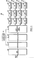
- FIG 1 is a block diagram of a transmitter in an OFDM system according to an embodiment of the present invention.
- a transmitter 100 of the present invention includes a cyclic redundancy code (CRC) generator 102, an encoder 104, a modulator 106, a multi-transmission mode portion 108, a controller 110, a plurality of inverse fast Fourier transform (IFFT) processors 112, 114, 116 and 118, a plurality of parallel-to-serial (P/S) converters 120, 122, 124 and 126, a plurality of radio frequency (RF) processors 128, 130, 132 and 134, and a plurality of transmit antennas 13 6, 13 8, 140 and 142.
- CRC cyclic redundancy code
- IFFT inverse fast Fourier transform
- P/S parallel-to-serial
- RF radio frequency
- the controller 110 determines a code rate, a modulation scheme, and an antenna transmission scheme according to feedback information (or transmission mode information) received from a receiver in an MS and correspondingly controls the encoder 104, the modulator 106, and the multi-transmission mode portion 108.
- the CRC generator 102 generates a CRC for input transmission data and attaches the CRC to the transmission data.
- the encoder 104 encodes the CRC-attached data at a predetermined code rate under the control of the controller 110 and outputs a codeword.
- k the code rate that the controller 110 tells the encoder 104 be denoted by R.
- R the code rate that the controller 110 tells the encoder 104 be denoted by R.
- the encoder 104 can be a convolutional encoder, a turbo encoder, or an LDPC (Low Density Parity Check) encoder.
- the modulator 106 modulates the coded data in a predetermined modulation scheme under the control of the controller 110. Specifically, the modulator 106 maps the input data into modulation symbols in accordance with the signal constellation of a modulation scheme (or a modulation order) that the controller 110 tells the modulator 106.
- the modulator 106 supports binary phase shift keying (BPSK), quadrature phase shift keying (QPSK), 8-quadrature phase shift keying (8-PSK), and 16QAM.
- BPSK binary phase shift keying
- QPSK quadrature phase shift keying
- 8-PSK 8-quadrature phase shift keying
- 16QAM 16QAM.
- the multi-transmission mode portion 108 encodes the modulation symbols in a predetermined method under the control of the controller 110, thereby producing a plurality of antenna signals. These antenna signals are provided respectively to their corresponding IFFT processors 112 to 118. Operations of the multi-transmission mode portion 108 will be described later in great detail with reference to FIGs. 2A, 2B and 2C.
- the IFFT processors 112 to 118 IFFT-process the received data.
- the P/S (Parallel to Serial) converters 120 to 126 serialize the IFFT signals received from their corresponding IFFT processors 112 to 118.
- the RF processors 128 to 134 convert the serial data received from their corresponding P/S converters 120 to 126 to analog signals, RF-process the analog signals, and output them to their corresponding transmit antennas 136 to 142.
- the RF processors 128 to 134 each include a filter and a front-end unit.
- the transmit antennas 136 to 142 radiate the received signals over the air. Specifically, the RF signal from the RF processor 128 is transmitted through the first transmit antenna 136, the RF signal from the RF processor 130 is transmitted through the second transmit antenna 138, the RF signal from the RF processor 132 is transmitted through the third transmit antenna 140, and the RF signal from the RF processor 134 is transmitted through the fourth transmit antenna 142.
- FIGs. 2A, 2B and 2C are diagrammatic representations of operations of the multi-transmission mode portion 108 illustrated in FIG. 1.
- FIG 2A is a block diagram of the multi-transmission mode portion 108 in the case where it operates in space-time block coding (STBC)
- FIG 2B is a block diagram of the multi-transmission mode portion 108 in the case where it operates in 2-layered spatial multiplexing (SM)
- FIG 2C is a block diagram of the multi-transmission mode portion 108 in the case where it operates in SM.
- STBC space-time block coding
- SM 2-layered spatial multiplexing
- the multi-transmission mode portion 108 needs a 4x4 STBC encoder 202, for STBC operation.
- the 4x4 STBC encoder 202 encodes the modulation symbols received from the modulator 106 in such a manner that four modulation symbols can be transmitted through four transmit antennas in four time intervals.
- four modulation symbols forming one antenna signal are mapped to predetermined four subcarriers or carried over predetermined two subcarriers for two time periods, rather than they are transmitted for four time periods.
- the multi-transmission mode portion 108 needs a serial-to-parallel (S/P) converter 206 and two 2x2 STBC encoders 208 and 210.
- the S/P converter 206 parallelizes the serial modulation symbols received from the modulator 106 illustrated in FIG. 1 and outputs odd-numbered modulation symbols to the first 2x2 STBC encoder 208 and even-numbered modulation symbols to the second 2x2 STBC encoder 210.
- the 2x2 STBC encoders 208 and 210 encode the input symbols so that two input symbols can be transmitted through two antennas for two time periods.
- two symbols forming one antenna signal are mapped to predetermined two subcarriers or carried over predetermined one subcarrier for two time periods, rather than they are transmitted just for two time periods.
- the multi-transmission mode portion 108 needs an S/P converter 214.
- the S/P converter 214 parallelizes the serial modulation symbols received from the modulator 106 illustrated in FIG. 1 and outputs the parallel modulation symbols to four antennas so that four modulation symbols can be transmitted through the four respective antennas for one time period.
- the multi-transmission mode portion 108 is so configured as to support the above three antenna transmission schemes. Yet, the antenna transmission schemes are merely exemplary applications to which the multi-transmission mode portion 108 is not limited.
- the three antenna transmission schemes have the following characteristics.
- the STBC is lowest in terms of data rate but highest in terms of diversity gain.
- the SM is highest in terms of data rate but lowest in terms of diversity gain. It is preferred, therefore, that a higher-rate antenna transmission scheme like the SM is used with a good channel state and a high-diversity gain antenna scheme like the STBC is used with a bad channel state.
- FIG 3 is a block diagram of a receiver in the OFDM system according to the embodiment of the present invention.
- the receiver of the present invention includes a plurality of receive antennas 300 to 302, a plurality of RF processors 304 to 306, a plurality of S/P converters 308 to 310, a plurality of fast Fourier transform (FFT) processors 312 to 314, a space-time processor 316, a P/S (Parallel to Serial) converter 318, a demodulator 320, a decoder 322, a CRC checker 324, and a feedback portion 326.
- FFT fast Fourier transform
- the RF processors 304 to 306 downconvert signals received from the transmit antennas 136 to 142 of the transmitter 100 through the receive antennas 300 to 302 to intermediate frequency (IF) signals and then to baseband signals, and convert the analog baseband signals to digital signals.
- IF intermediate frequency
- the S/P converters 308 to 310 parallelize the serial data received from their corresponding RF processors 304 to 306.
- the FFT processors 312 to 314 FFT-process the parallel data received from their corresponding P/S converters 308 to 310.
- the space-time processor 316 decodes the FFT signals in a predetermined method corresponding to the transmission scheme of the multi-transmission mode portion 108 in the transmitter 100, thereby estimating the input signal of the multi-transmission mode portion 108.
- the P/S converter 318 serializes the parallel data received from the space-time processor 316.
- the demodulator 320 demodulates the serial data, thereby estimating bits mapped to modulation symbols.
- the decoder 322 decodes the demodulated data in accordance with the operation of the encoder 104 and outputs an information word including a CRC to the CRC checker 324. That is, the decoder 322 determines the information bits input to the encoder 104.
- the CRC checker 324 checks the CRC of the decoded data on the basis of a predetermined data unit, for example, on a frame basis in order to determine whether the decoded data is identical to the input data of the transmitter 100. If they are identical, no CRC error is generated. If they are different, a CRC error occurs.
- the CRC check result (acknowledgement: ACK or non-acknowledgement: NACK) is provided to the feedback portion 326. In the absence of a CRC error, the decoded data is output.
- the feedback portion 326 determines feedback information (i.e., transmission mode information) to be transmitted to the transmitter 100 according to the CRC check result
- the transmission mode information is used to determine an AMC level and/or an antenna transmission scheme.
- FIG. 4 is a detailed block diagram of the feedback portion 326 illustrated in FIG. 3.
- the feedback portion 326 is comprised of a first transmission mode decider 400, a second transmission mode decider 402, a third transmission mode decider 404, and a transmission mode selector 406.
- the operations of the first, second and third transmission mode deciders 400, 402 and 404 will be described later in great detail with reference to FIGs. 5A & 5B, 6A & 6B and 7A & 7B, respectively.
- the first, second and third transmission mode deciders 400, 402 and 404 channel-adaptively change thresholds in different manners according to the CRC check result from the CRC checker 220, compare the changed thresholds with an SNR as a channel quality indicator (CQI) measurement, and decide on a transmission mode according to the comparison results.
- the receiver decides on a transmission mode using an SNR versus throughput graph illustrating the mapping relationship between SNR measurements and transmission modes. For example, if an SNR measurement is less than a predetermined threshold, a first transmission mode is chosen and if the SNR measurement is larger than the threshold, a second transmission mode is chosen, referring to the SNR versus throughput graph.
- the SNR versus throughput graph (or the threshold) is confined to a particular channel model and thus may not be appropriate under a changed fading environment. Accordingly, the present invention characteristically changes the threshold according to the CRC check result of received data and decides on a transmission mode based on the changed threshold. Adaptation of the SNR versus throughput graph (or the threshold) to the current channel state leads to more reliable decision on a transmission mode.
- the transmission mode deciders 400, 402 and 404 each have a memory table associated with a predetermined SNR versus throughput curve, adjust thresholds that divide the curve into a plurality of regions according to the CRC check result, and determine a curve area corresponding to the SNR measurement, thereby determining a transmission mode.
- the transmission mode selector 406 selects one of the outputs of the first, second and third transmission mode deciders 400, 402 and 404 and feeds back information about the selected transmission mode to the transmitter.
- the transmission mode information includes at least one of a coding method, a modulation scheme, and an antenna transmission scheme.
- all or at least one of the three transmission mode deciders 400, 402 and 404 may be provided to the receiver. If it has a plurality of transmission mode deciders, the receiver determines a transmission mode by selecting one of the transmission mode deciders under a given situation.
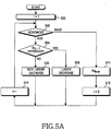
- FIG 5A is a flowchart illustrating a threshold determining operation in the first transmission mode decider 400.
- the first transmission mode decider 400 sets a time index i to 1 to start communications in step 500.
- the first transmission mode decider 400 determines a transmission mode based on an initial threshold TH initial calculated under a severe-distortion channel environment such as an AWGN (Additive White Noise) channel environment.
- the first transmission mode decider 400 determines a threshold in the following way in order to decide on a transmission mode.
- the first transmission mode decider 400 first checks the CRC check result received from the CRC checker 324 in step 502. If the CRC check result is an ACK, the first transmission mode decider 400 compares a predetermined reference value with an existing threshold, TH i-1 in step 504. If the existing threshold, TH i-1 is equal to or larger than the reference value (TH i-1 ⁇ reference), the first transmission mode decider 400 calculates a new threshold, TH i non-linearly in step 506 and proceeds to step 514.
- the first transmission mode decider 400 calculates a new threshold, TH i by the following Equation (2) in step 508 and proceeds to step 514.
- TH i TH i-1 - ⁇
- the first transmission mode decider 400 sets the initial threshold, TH initial as a new threshold TH i in step 510.
- the first transmission mode decider 400 sets the time index i to 0 in step 512 and proceeds to step 514.
- TH i TH initial
- step 514 the first transmission mode decider 400 increases the time index i by 1 and returns to step 502.
- FIG. 5B is a graph illustrating changes in the threshold in accordance with the operation of the first transmission mode decider 400.
- communications start using the initial threshold obtained under the severe-distortion channel environment. Then, if the CRC check of a received frame turns out an ACK, an existing threshold is decreased by the product of the predetermined value A and the time index i. As successive ACKs drop the threshold below the predetermined reference value, the threshold is decreased by the predetermined value ⁇ . If a NACK is generated during this operation, the threshold is returned to the initial threshold and then decreased again in the method described above.
- FIG 6A is a flowchart illustrating a threshold determining operation in the second transmission mode decider 402.
- the second transmission mode decider 402 operates in a different manner from the first transmission mode decider 400 in that a threshold is linearly decreased directly without non-linear changes because a typical channel environment is assumed.
- the second transmission mode decider 402 sets the time index i to 1 to start communications in step 600.
- the second transmission mode decider 402 determines a transmission mode based on an initial threshold TH initial calculated over a typical channel.
- the second transmission mode decider 402 determines thresholds to decide on a transmission mode, as follows.
- the second transmission mode decider 402 first checks the CRC check result received from the CRC checker 324 of FIG 3 in step 602. If the CRC check result is an ACK, the second transmission mode decider 402 calculates a new threshold, TH i by subtracting a predetermined value A from an existing threshold TH i-1 in step 604 and proceeds to step 612. That is, the second transmission mode decider 402 directly decreases the threshold linearly, as compared to the first transmission mode decider 400.
- the second transmission mode decider 402 compares the existing threshold TH i-1 with a predetermined reference value in step 606. If the existing threshold TH i-1 is less than the reference value, the second transmission mode decider 402 sets the initial threshold, TH initial as a new threshold TH i in step 608 and proceeds to step 612.
- TH i TH initial
- FIG 6B is a graph illustrating changes in the threshold in accordance with the operation of the second transmission mode decider 402.
- communications start using the initial threshold obtained under the typical channel environment.
- the communications start with a threshold lower than the initial threshold for the first transmission mode decider 400. If the CRC check of a received frame turns out an ACK, the existing threshold is decreased by the predetermined value A. If the CRC check of the received frame turns out a NACK, the existing threshold is returned to the initial threshold and then decreased linearly again in the method described above. Due to the assumption of a typical channel environment, the first CRC check result can be a NACK, as compared to the channel environment in which the first transmission mode decider 400 operates. Therefore, if a NACK occurs in the state where the existing threshold is equal to or greater than the initial threshold, a new threshold is calculated by adding the predetermined value to the existing threshold.
- FIG 7A is a flowchart illustrating a threshold determining operation in the third transmission mode decider 404.
- the third transmission mode decider 404 combines the operations of the first and second transmission mode deciders 400 and 402. Specifically, the third transmission mode decider 404 uses a threshold calculated under the severe-distortion channel environment as an initial threshold. If a NACK is generated, the third transmission mode decider 404 changes an existing threshold to a predetermined value without returning to the initial threshold. If another NACK follows, the third transmission mode decider 404 maintains the changed threshold. However, if m successive NACKs are generated, the third transmission mode decider 404 returns to the initial threshold and then operates in the same manner as the second transmission mode decider 402.
- the third transmission mode decider 404 sets the time index i to 1 to start communications and initializes its operation mode to the operation of the first transmission mode decider 400 (hereinafter, referred to as a first mode) in step 700.
- the third transmission mode decider 404 determines whether the NACK is another one, that is, whether the previous CRC check result is a NACK in step 708. If the previous CRC check result is an ACK, the third transmission mode decider 404 sets the new threshold TH i to a predetermined first value in step 710 and proceeds to step 722. For example, the first value can be the threshold before the current NACK. On the contrary, if the previous CRC check result is a NACK, the third transmission mode decider 404 counts the number of successive NACKs in step 712.
- the third transmission mode decider 404 sets the new threshold TH i to an initial threshold TH initial calculated under the worst channel environment, considering that the successive NACK occurrences arose from a bad channel condition in step 718.
- step 720 the third transmission mode decider 404 transitions to the operation mode of the second transmission mode decider 402 (hereinafter, referred to as a second mode) and proceeds to step 722.
- step 722 the third transmission mode decider 404 increases the time index i by 1 and returns to step 702.
- the third transmission mode decider 404 checks the CRC check result in step 724. If the CRC check result is an ACK, the third transmission mode decider 404 decreases the existing threshold TH i-1 linearly in step 726 and proceeds to step 722. If the CRC check result is a NACK, the third transmission mode decider 404 sets the new threshold TH i to a predetermined second value in step 728 and then goes to step 722.
- FIG 7B is a graph illustrating changes in the threshold according to the operation of the third transmission mode decider 404.
- communications start using the initial threshold obtained under the severe-distortion channel environment. Then, if the CRC check of a received frame turns out an ACK, the threshold is decreased non-linearly in the manner of the first transmission mode decider 400. If the CRC check of the received frame turns out a NACK, the threshold is changed to the predetermined first value. If an ACK is generated subsequently, the threshold is decreased non-linearly, and if m successive NACKs are generated, the threshold is changed to the initial threshold. Then, the threshold is changed in the manner of the second transmission mode decider 402. Specifically, in the case of an ACK, the threshold is linearly decreased, and in the case of a NACK, the threshold is changed to the predetermined second value.
- the transmitter first generates a CRC for transmission data, encodes and modulates the CRC-attached transmission data, and transmits the modulated data through the transmit antennas in one of multi-antenna transmission schemes that the multi-transmission mode portion 108 supports.
- the transmitter determines a code rate, a modulation scheme and an antenna transmission scheme according to feedback information or transmission mode information received from the receiver.
- a predetermined code rate, modulation scheme and antenna transmission scheme are used for an initial transmission.
- the receiver recovers a received signal and performs a CRC check on the signal. If the CRC check result is an ACK, a threshold is decreased to thereby select a transmission mode suitable for a better fading situation. If the CRC check result is a NACK, the threshold is increased to thereby select a transmission mode suitable for a worse fading situation.
- the threshold can be changed in the above-described three methods. As described before, the threshold adjustment is a process of adapting the SNR versus throughput graph to the current channel state to decide on a transmission mode.
- the receiver (MS) determines a transmission mode involving a code rate, a modulation scheme and an antenna transmission scheme and feeds back transmission mode information to the transmitter (BS). It can be further contemplated as an alternative embodiment that the receiver (MS) feeds back a CQI and the CRC check result (ACK or NACK) of a frame and the transmitter (BS) determines a transmission mode based on the feedback information.
- the receiver (MS) feeds back a CQI and the CRC check result (ACK or NACK) of a frame and the transmitter (BS) determines a transmission mode based on the feedback information.
- the transmitter and the receiver according to an alternative embodiment of the present invention have the configurations illustrated in FIGs. 1 and 3, respectively. Yet, they operate partially in different manners from the transmitter and the receiver in the first embodiment of the present invention described above.
- the feedback portion 326 feeds back the CRC check result of the CRC checker 324 and a CQI to the transmitter 100 and the transmitter 100 determines a transmission mode based on the feedback information.
- the controller 110 changes SNR versus throughput graphs according to the feedback information and determines a transmission mode based on the changed graphs. Therefore, the controller 110 includes the feedback portion having the configuration illustrated in FIG 4 and determines a transmission mode in one of the procedures illustrated in FIGs. 5A, 6A and 7A. These transmission mode deciding procedures have been described before in great detail and so, are not described again here.
- the receiver first performs a CRC check on data received from the transmitter and feeds back the CRC check result and a CQI to the transmitter.
- the transmitter generates a CRC for transmission data, encodes and modulates the CRC-attached transmission data, and transmits the modulated data through the transmit antennas in one of multi-antenna transmission schemes that the multi-transmission mode portion 108 supports.
- the transmitter determines a code rate, a modulation scheme and an antenna transmission scheme according to the feedback information or transmission mode information received from the receiver and transmits the data in the decided transmission mode. If the CRC check result is an ACK, a threshold is decreased for an SNR versus throughput graph to thereby select a transmission mode suitable for a better fading situation. If the CRC check result is a NACK, the threshold is increased to thereby select a transmission mode suitable for a worse fading situation.
- the threshold can be changed in the above-described three methods.
- FIG. 8 is a conceptual SNR versus throughput graph for use in determining a transmission mode according to an embodiment of the present invention. In the illustrated case, four transmission modes are defined.
- a first transmission mode is set for an SNR less than a first threshold, TH1.
- the transmitter transmits data at a code rate of 1/2, in QPSK, and using the STBC scheme.
- a second transmission mode is set for an SNR between the first threshold, TH 1 and a second threshold, TH2.
- the transmitter transmits data at a code rate of 3/4, in 16QAM, and using the 2-layered SM.
- a third transmission mode is set for an SNR between the second threshold, TH 2 and a third threshold, TH3.
- the transmitter transmits data at a code rate of 6/7, in 16QAM, and using the 2-layered SM.
- a fourth transmission mode is set for an SNR above the third threshold, TH3. In the fourth transmission mode, the transmitter transmits data at a code rate of 3/4, in 64QAM, and using the SM.
- the thresholds TH1, TH2 and TH3 are changed according to the CRC check result, thereby selecting a transmission mode suitable for the current channel state. For example, if the CRC check result is a NACK, the thresholds TH1, TH2 and TH3 are shifted to the right so that a transmission mode can be selected for a bad
Abstract
Description
- This application claims priority under 35 U.S.C. § 119 to an application entitled "Apparatus And Method For Controlling Transmission Mode In A MIMO Mobile Communication System" filed in the Korean Intellectual Property Office on June 14, 2004 and assigned Serial No. 2004-43402, the contents of which are incorporated herein by reference.
- The present invention relates generally to a mobile communication system, and in particular, to a transmitting/receiving apparatus and method for ensuring high data rate and high reliability in a multiple-input multiple-output (MIMO) mobile communication system.
- Adaptive Modulation and Coding (AMC) is actively studied to increase channel capacity in wireless networks. The AMC scheme adapts a modulation scheme and a code rate according to the current signal quality or channel state, while keeping transmit power constant during transmission of one frame, to increase data rate. For example, assume a nearby mobile station (MS) has a small error probability in receiving signals from a base station (BS). The nearby MS uses a high-order modulation scheme such as 16-ary quadrature amplitude modulation (16QAM) in which four bits form one signal, and a high code rate such as 3/4. As a remote MS receives signals with a high error probability from the BS, the remote MS uses a low-order modulation scheme and a low code rate to receive signals without errors.
- In AMC, the transmission scheme used is decided with respect to a plurality of code rates and modulation schemes depending on what region a signal-to-noise ratio (SNR) measured at a receiver belongs to in an SNR versus throughput graph (or curve). However, the SNR versus throughput graph is derived from a particular fading channel model, which implies that the SNR versus throughput graph may not be viable in a changed fading environment. Accordingly, a need exists for a new method of selecting a transmission scheme.
- Typically, multiple antennas are used for two purposes: one is to increase data reliability and the other is to increase data rate. To achieve a higher reliability and a higher data rate, the data reliability increasing scheme is adopted in a bad channel state and the data rate increasing scheme is adopted in a good channel state. Obviously, the adaptive use of a multiple antenna scheme according to a channel state leads to the increase of data rate and data reliability.
- In this context, combining the traditional AMC scheme and a multiple transmit/receive antenna scheme has emerged as a significant issue for future communication systems. Satisfactory data rate and reliability can be achieved by optimizing a modulation scheme, a code rate, and an antenna transmission scheme according to a channel state, taking into account both the AMC and the multiple antenna scheme which serve the same purpose.
- Technologies of exploiting multiple antennas have been studied to build a high-speed, reliable communication system that maximizes data transmission rate and minimizes an error rate with limited radio resources. These technologies are called space-time processing.
- Space-time processing was developed to cope with problems encountered in a wireless environment, such as signal loss and unexpected channel state degradation. With their introduction in the 1960's, beam-forming algorithms are now an area of active study for the purpose of increasing cell capacities and antenna gains on the forward link and the reverse link. As is well known, the Space Time Coding (STC) proposed by Tarokh, et. al in 1997 achieves a diversity effect proportional to the product of the number of transmit and receive antennas.
- Considerable efforts have also been made to exploit multiple antennas for increasing data transmission rate as well as for improving reception performance as described above. One of the most prominent data rate increasing methods is spatial multiplexing (SM). The SM is a scheme of transmitting different information data through different transmit antennas. Telta, et. al.'s study results reveal that the SM brings as much an increase in capacity as the number of transmit antennas, compared to single-input single-output (SISO). The capacity increase is significant to a high-speed data transmission system.
- The STC aims to reduce the error rate of transmission data and the SM is used to maximize the data rate of transmission data. One method that serves both purposes is 2-layered SM. For example, in a system where four transmit antennas act as two transmit antennas by grouping, two STBC blocks corresponding to the two transmit antennas can be connected. In this case, a higher data rate is achieved than in an STBC scheme using four antennas, and a lower error rate than in an SM method using four antennas.
- As described above, there exist a variety of MIMO (Multiple-Input Multiple-Output) schemes according to the numbers of transmit antennas and receive antennas in the communication system. Therefore, system capacity depends on which one is selected for data transmission/reception among the various antenna combinations.
- Accordingly, a need exists for developing a method of determining an antenna transmission scheme according to a fading channel environment, while still applying the traditional AMC scheme, in a MIMO system.
- An object of the present invention is to substantially solve at least the above problems and/or disadvantages and to provide at least the advantages below. Accordingly, an object of the present invention is to provide an apparatus and method for controlling a code rate, a modulation scheme, and an antenna transmission scheme according to a channel state in a MIMO mobile communication system.
- Another object of the present invention is to provide an apparatus and method for changing a criterion to determine a transmission mode according to a channel state and controlling a code rate, a modulation scheme, and an antenna transmission scheme according to the changed criterion in a MIMO mobile communication system.
- The above objects are achieved by providing an apparatus and method for controlling a transmission mode in a MIMO mobile communication system. According to an aspect of the present invention, in a receiver in a MIMO mobile communication system, an error checker checks errors in received data and outputs an error check result. A feedback portion adaptively changes a threshold associated with a channel state according to the error check result, and determines a transmission mode by comparing the changed threshold with a measured CQI (Channel Quality Indicator), and feeds back transmission mode information to a transmitter.
- According to another aspect of the present invention, in a transmitter in a MIMO mobile communication system, a receiving portion receives a CQI and the error check result of transmitted data from an MS. A controller adaptively changes a threshold associated with a channel state according to the error check result and determines a transmission mode by comparing the changed threshold with the received CQI.
- According to a further aspect of the present invention, in a method of adaptively changing a threshold according to a channel state, an existing threshold is used to compare with a CQI for determining a transmission mode, a threshold calculated under a severe-distortion channel environment is set as an initial threshold. If the CRC (Cyclic Redundancy Code) check result of a frame received at a receiver is an ACK, an existing threshold is compared with a predetermined reference value. If the existing threshold is equal to or greater than the reference value, the existing threshold is non-linearly decreased. If the existing threshold is less than the reference value, the existing threshold is linearly decreased. If the CRC check result is a NACK, the existing threshold is changed to the initial threshold.
- According to still another aspect of the present invention, in a method of adaptively changing a threshold according to a channel state, the threshold being compared with a CQI for determining a transmission mode, a threshold calculated under a typical channel environment is set as an initial threshold. If the CRC check result of a frame received at a receiver is an ACK, an existing threshold is linearly decreased. If the CRC check result is a NACK, the existing threshold is changed to the initial threshold.
- According to still further aspect of the present invention, in a method of adaptively changing a threshold according to a channel state, the threshold being compared with a CQI for determining a transmission mode, a threshold calculated under a severe-distortion channel environment is set as an initial threshold. If the CRC check result of a frame received at a receiver is an ACK, an existing threshold is non-linearly decreased. If the CRC check result is a NACK, it is determined whether a previous CRC check result is an ACK or a NACK. If the previous CRC check result is an ACK, the existing threshold is increased to a predetermined first value. If the previous CRC check result is a NACK, the number of successive NACKs is counted. If the count is less than a predetermined value, the existing threshold is maintained, and if the count is equal to or greater than the predetermined value, the existing threshold is changed to the initial threshold. If an ACK follows, the initial threshold is linearly decreased, and if a NACK follows, the initial threshold is changed to a predetermined second value.
- According to yet another aspect of the present invention, in a feeding back method in a receiver in a MIMO mobile communication system, errors are checked in received data and an error check result is output A threshold associated with a channel state is adaptively changed according to the error check result. A transmission mode is determined by comparing the changed threshold with a measured CQI, and transmission mode information is fed back to a transmitter.
- According to yet a further aspect of the present invention, in a transmitting method in a MIMO mobile communication system, a CQI and the error check result of transmitted data are received from a receiver. A threshold associated with a channel state is adaptively changed according to the error check result and a transmission mode is determined by comparing the changed threshold with the received CQI.
- The above and other objects, features and advantages of the present invention will become more apparent from the following detailed description when taken in conjunction with the accompanying drawings in which:
- FIG. 1 is a block diagram of a transmitter in an OFDM system according to an embodiment of the present invention;
- FIGs. 2A, 2B and 2C are diagrammatic representations of operations of a multi-transmission mode portion illustrated in FIG 1;
- FIG 3 is a block diagram of a receiver in the OFDM system according to an embodiment of the present invention;
- FIG. 4 is a detailed block diagram of a feedback portion illustrated in FIG 3;
- FIG. 5A is a flowchart illustrating a threshold determining operation in the first transmission mode decider illustrated in FIG 4;
- FIG. 5B is a graph illustrating changes in a threshold in accordance with the operation of a first transmission mode decider according to an embodiment of the present invention;
- FIG. 6A is a flowchart illustrating a threshold determining operation in the second transmission mode decider illustrated in FIG 4;
- FIG. 6B is a graph illustrating changes in a threshold in a second transmission mode decider according to an embodiment of the present invention;
- FIG 7A is a flowchart illustrating a threshold determining operation in the third transmission mode decider illustrated in FIG. 4;
- FIG 7B is a graph illustrating changes in a threshold in a third transmission mode decider according to an embodiment of the present invention; and
- FIG. 8 is a conceptual SNR versus throughput graph according to an embodiment of the present invention.
-
- Preferred embodiments of the present invention will be described herein below with reference to the accompanying drawings. In the following description, well-known functions or constructions are not described in detail since they would obscure the invention in unnecessary detail.
- The present invention is intended to provide a method of changing a criterion to determine a transmission mode according to a channel state and controlling a code rate, a modulation scheme, and an antenna transmission scheme according to the changed criterion in a MIMO mobile communication system.
- It is to be appreciated that the following description is made of the present invention in the context of a communication system having a transmitter with four transmit antennas and a receiver with two receive antennas and a communication system having a transmitter with four transmit antennas and a receiver with four receive antennas. Yet, it is clear that there are other various MIMO schemes than those described herein.
- While the present invention is applicable to any of frequency division multiple access (FDMA), time division multiple access (TDMA), code division multiple access (CDMA), and orthogonal frequency division multiplexing (OFDM) systems, the OFDM system is taken as an example, for notational simplicity.
- FIG 1 is a block diagram of a transmitter in an OFDM system according to an embodiment of the present invention.
- Referring to FIG 1, a
transmitter 100 of the present invention includes a cyclic redundancy code (CRC)generator 102, anencoder 104, amodulator 106, amulti-transmission mode portion 108, acontroller 110, a plurality of inverse fast Fourier transform (IFFT)processors converters processors - In operation, the
controller 110 determines a code rate, a modulation scheme, and an antenna transmission scheme according to feedback information (or transmission mode information) received from a receiver in an MS and correspondingly controls theencoder 104, themodulator 106, and themulti-transmission mode portion 108. - The
CRC generator 102 generates a CRC for input transmission data and attaches the CRC to the transmission data. Theencoder 104 encodes the CRC-attached data at a predetermined code rate under the control of thecontroller 110 and outputs a codeword. Here, let the length of an input information word be denoted by k and the code rate that thecontroller 110 tells theencoder 104 be denoted by R. Then, the length of the codeword is n (=k/R). Theencoder 104 can be a convolutional encoder, a turbo encoder, or an LDPC (Low Density Parity Check) encoder. - The
modulator 106 modulates the coded data in a predetermined modulation scheme under the control of thecontroller 110. Specifically, themodulator 106 maps the input data into modulation symbols in accordance with the signal constellation of a modulation scheme (or a modulation order) that thecontroller 110 tells themodulator 106. Themodulator 106 supports binary phase shift keying (BPSK), quadrature phase shift keying (QPSK), 8-quadrature phase shift keying (8-PSK), and 16QAM. One bit (s=1) is mapped to one complex signal in BPSK, two bits (s=2) to one complex signal in QPSK, three bits (s=3) to one complex signal in 8PSK, and four bits (s=4) to one complex signal in 16QAM. - The
multi-transmission mode portion 108 encodes the modulation symbols in a predetermined method under the control of thecontroller 110, thereby producing a plurality of antenna signals. These antenna signals are provided respectively to their corresponding IFFT processors 112 to 118. Operations of themulti-transmission mode portion 108 will be described later in great detail with reference to FIGs. 2A, 2B and 2C. - The IFFT processors 112 to 118 IFFT-process the received data. The P/S (Parallel to Serial)
converters 120 to 126 serialize the IFFT signals received from their corresponding IFFT processors 112 to 118. - The
RF processors 128 to 134 convert the serial data received from their corresponding P/S converters 120 to 126 to analog signals, RF-process the analog signals, and output them to their corresponding transmitantennas 136 to 142. TheRF processors 128 to 134 each include a filter and a front-end unit. - The transmit
antennas 136 to 142 radiate the received signals over the air. Specifically, the RF signal from theRF processor 128 is transmitted through the first transmitantenna 136, the RF signal from theRF processor 130 is transmitted through the second transmitantenna 138, the RF signal from theRF processor 132 is transmitted through the third transmitantenna 140, and the RF signal from theRF processor 134 is transmitted through the fourth transmitantenna 142. - FIGs. 2A, 2B and 2C are diagrammatic representations of operations of the
multi-transmission mode portion 108 illustrated in FIG. 1. Specifically, FIG 2A is a block diagram of themulti-transmission mode portion 108 in the case where it operates in space-time block coding (STBC), FIG 2B is a block diagram of themulti-transmission mode portion 108 in the case where it operates in 2-layered spatial multiplexing (SM), and FIG 2C is a block diagram of themulti-transmission mode portion 108 in the case where it operates in SM. - Referring to FIG 2A, the
multi-transmission mode portion 108 needs a4x4 STBC encoder 202, for STBC operation. The4x4 STBC encoder 202 encodes the modulation symbols received from themodulator 106 in such a manner that four modulation symbols can be transmitted through four transmit antennas in four time intervals. In the OFDM system, four modulation symbols forming one antenna signal are mapped to predetermined four subcarriers or carried over predetermined two subcarriers for two time periods, rather than they are transmitted for four time periods. - Referring to FIG. 2B, for 2-layered SM, the
multi-transmission mode portion 108 needs a serial-to-parallel (S/P)converter 206 and two2x2 STBC encoders P converter 206 parallelizes the serial modulation symbols received from themodulator 106 illustrated in FIG. 1 and outputs odd-numbered modulation symbols to the first2x2 STBC encoder 208 and even-numbered modulation symbols to the second2x2 STBC encoder 210. The2x2 STBC encoders - Referring to FIG 2C, for SM operation, the
multi-transmission mode portion 108 needs an S/P converter 214. The S/P converter 214 parallelizes the serial modulation symbols received from themodulator 106 illustrated in FIG. 1 and outputs the parallel modulation symbols to four antennas so that four modulation symbols can be transmitted through the four respective antennas for one time period. - The
multi-transmission mode portion 108 is so configured as to support the above three antenna transmission schemes. Yet, the antenna transmission schemes are merely exemplary applications to which themulti-transmission mode portion 108 is not limited. - For four transmit antennas, for instance, the three antenna transmission schemes have the following characteristics.
STBC 2-layered SM SM Data rate 1 2 4 Diversity gain 4 2 None - As noted from Table 1, the STBC is lowest in terms of data rate but highest in terms of diversity gain. On the other hand, the SM is highest in terms of data rate but lowest in terms of diversity gain. It is preferred, therefore, that a higher-rate antenna transmission scheme like the SM is used with a good channel state and a high-diversity gain antenna scheme like the STBC is used with a bad channel state.
- Now a description will be made of the configuration of a receiver being the counterpart of the
transmitter 100. - FIG 3 is a block diagram of a receiver in the OFDM system according to the embodiment of the present invention.
- Referring to FIG 3, the receiver of the present invention includes a plurality of receive
antennas 300 to 302, a plurality ofRF processors 304 to 306, a plurality of S/P converters 308 to 310, a plurality of fast Fourier transform (FFT)processors 312 to 314, a space-time processor 316, a P/S (Parallel to Serial)converter 318, ademodulator 320, adecoder 322, aCRC checker 324, and afeedback portion 326. - In operation, the
RF processors 304 to 306 downconvert signals received from the transmitantennas 136 to 142 of thetransmitter 100 through the receiveantennas 300 to 302 to intermediate frequency (IF) signals and then to baseband signals, and convert the analog baseband signals to digital signals. - The S/
P converters 308 to 310 parallelize the serial data received from theircorresponding RF processors 304 to 306. TheFFT processors 312 to 314 FFT-process the parallel data received from their corresponding P/S converters 308 to 310. - The space-
time processor 316 decodes the FFT signals in a predetermined method corresponding to the transmission scheme of themulti-transmission mode portion 108 in thetransmitter 100, thereby estimating the input signal of themulti-transmission mode portion 108. - The P/
S converter 318 serializes the parallel data received from the space-time processor 316. Thedemodulator 320 demodulates the serial data, thereby estimating bits mapped to modulation symbols. - The
decoder 322 decodes the demodulated data in accordance with the operation of theencoder 104 and outputs an information word including a CRC to theCRC checker 324. That is, thedecoder 322 determines the information bits input to theencoder 104. - The
CRC checker 324 checks the CRC of the decoded data on the basis of a predetermined data unit, for example, on a frame basis in order to determine whether the decoded data is identical to the input data of thetransmitter 100. If they are identical, no CRC error is generated. If they are different, a CRC error occurs. The CRC check result (acknowledgement: ACK or non-acknowledgement: NACK) is provided to thefeedback portion 326. In the absence of a CRC error, the decoded data is output. - The
feedback portion 326 determines feedback information (i.e., transmission mode information) to be transmitted to thetransmitter 100 according to the CRC check result The transmission mode information is used to determine an AMC level and/or an antenna transmission scheme. - FIG. 4 is a detailed block diagram of the
feedback portion 326 illustrated in FIG. 3. - Referring to FIG. 4, the
feedback portion 326 is comprised of a firsttransmission mode decider 400, a secondtransmission mode decider 402, a thirdtransmission mode decider 404, and atransmission mode selector 406. The operations of the first, second and thirdtransmission mode deciders - In operation, the first, second and third
transmission mode deciders - The SNR versus throughput graph (or the threshold) is confined to a particular channel model and thus may not be appropriate under a changed fading environment. Accordingly, the present invention characteristically changes the threshold according to the CRC check result of received data and decides on a transmission mode based on the changed threshold. Adaptation of the SNR versus throughput graph (or the threshold) to the current channel state leads to more reliable decision on a transmission mode. Thus, the
transmission mode deciders - The
transmission mode selector 406 selects one of the outputs of the first, second and thirdtransmission mode deciders transmission mode deciders - FIG 5A is a flowchart illustrating a threshold determining operation in the first
transmission mode decider 400. - Referring to FIG 5A, the first
transmission mode decider 400 sets a time index i to 1 to start communications instep 500. For the first frame or feedback information, the firsttransmission mode decider 400 determines a transmission mode based on an initial threshold THinitial calculated under a severe-distortion channel environment such as an AWGN (Additive White Noise) channel environment. For the following frames, the firsttransmission mode decider 400 determines a threshold in the following way in order to decide on a transmission mode. - The first
transmission mode decider 400 first checks the CRC check result received from theCRC checker 324 instep 502. If the CRC check result is an ACK, the firsttransmission mode decider 400 compares a predetermined reference value with an existing threshold, THi-1 instep 504. If the existing threshold, THi-1 is equal to or larger than the reference value (THi-1≥reference), the firsttransmission mode decider 400 calculates a new threshold, THi non-linearly instep 506 and proceeds to step 514. Specifically, the firsttransmission mode decider 400 subtracts the product of a predetermined value A and the time index i from the existing threshold THi-1, thereby producing the new threshold, THi, as set forth in Equation (1): - If the existing threshold THi-1 is less than the reference value (THi-1<reference), the first
transmission mode decider 400 calculates a new threshold, THi by the following Equation (2) instep 508 and proceeds to step 514. - On the other hand, in the case of a NACK in
step 502, the firsttransmission mode decider 400 sets the initial threshold, THinitial as a new threshold THi instep 510. The firsttransmission mode decider 400 sets the time index i to 0 instep 512 and proceeds to step 514. Thus, in Equation (3): - In
step 514, the firsttransmission mode decider 400 increases the time index i by 1 and returns to step 502. - FIG. 5B is a graph illustrating changes in the threshold in accordance with the operation of the first
transmission mode decider 400. - Referring to FIG 5B, communications start using the initial threshold obtained under the severe-distortion channel environment. Then, if the CRC check of a received frame turns out an ACK, an existing threshold is decreased by the product of the predetermined value A and the time index i. As successive ACKs drop the threshold below the predetermined reference value, the threshold is decreased by the predetermined value Δ. If a NACK is generated during this operation, the threshold is returned to the initial threshold and then decreased again in the method described above.
- FIG 6A is a flowchart illustrating a threshold determining operation in the second
transmission mode decider 402. The secondtransmission mode decider 402 operates in a different manner from the firsttransmission mode decider 400 in that a threshold is linearly decreased directly without non-linear changes because a typical channel environment is assumed. - Referring to FIG. 6A, the second
transmission mode decider 402 sets the time index i to 1 to start communications instep 600. For the first reverse link frame or feedback information, the secondtransmission mode decider 402 determines a transmission mode based on an initial threshold THinitial calculated over a typical channel. For the following frames, the secondtransmission mode decider 402 determines thresholds to decide on a transmission mode, as follows. - The second
transmission mode decider 402 first checks the CRC check result received from theCRC checker 324 of FIG 3 instep 602. If the CRC check result is an ACK, the secondtransmission mode decider 402 calculates a new threshold, THi by subtracting a predetermined value A from an existing threshold THi-1 instep 604 and proceeds to step 612. That is, the secondtransmission mode decider 402 directly decreases the threshold linearly, as compared to the firsttransmission mode decider 400. The new threshold THi is computed by Equation (4): - On the other hand, in the case of a NACK in
step 602, the secondtransmission mode decider 402 compares the existing threshold THi-1 with a predetermined reference value instep 606. If the existing threshold THi-1 is less than the reference value, the secondtransmission mode decider 402 sets the initial threshold, THinitial as a new threshold THi instep 608 and proceeds to step 612. Thus, in Equation (5): - If the existing threshold THi-1 is equal to or larger than the reference value, the second
transmission mode decider 402 calculates a new threshold THi by adding the predetermined value A to the existing threshold THi-1 instep 610 and proceeds to step 612. That is, in Equation (6): - FIG 6B is a graph illustrating changes in the threshold in accordance with the operation of the second
transmission mode decider 402. - Referring to FIG 6B, communications start using the initial threshold obtained under the typical channel environment. In other words, the communications start with a threshold lower than the initial threshold for the first
transmission mode decider 400. If the CRC check of a received frame turns out an ACK, the existing threshold is decreased by the predetermined value A. If the CRC check of the received frame turns out a NACK, the existing threshold is returned to the initial threshold and then decreased linearly again in the method described above. Due to the assumption of a typical channel environment, the first CRC check result can be a NACK, as compared to the channel environment in which the firsttransmission mode decider 400 operates. Therefore, if a NACK occurs in the state where the existing threshold is equal to or greater than the initial threshold, a new threshold is calculated by adding the predetermined value to the existing threshold. - FIG 7A is a flowchart illustrating a threshold determining operation in the third
transmission mode decider 404. The thirdtransmission mode decider 404 combines the operations of the first and secondtransmission mode deciders transmission mode decider 404 uses a threshold calculated under the severe-distortion channel environment as an initial threshold. If a NACK is generated, the thirdtransmission mode decider 404 changes an existing threshold to a predetermined value without returning to the initial threshold. If another NACK follows, the thirdtransmission mode decider 404 maintains the changed threshold. However, if m successive NACKs are generated, the thirdtransmission mode decider 404 returns to the initial threshold and then operates in the same manner as the secondtransmission mode decider 402. - Referring to FIG 7A, the third
transmission mode decider 404 sets the time index i to 1 to start communications and initializes its operation mode to the operation of the first transmission mode decider 400 (hereinafter, referred to as a first mode) instep 700. - In
step 702, the thirdtransmission mode decider 404 checks the current operation mode. If it is the first mode, the thirdtransmission mode decider 404 checks the CRC check result of theCRC checker 324 illustrated in FIG. 3 instep 704. If the CRC check result is an ACK, the thirdtransmission mode decider 404 decreases an existing threshold THi-1 non-linearly instep 706 and proceeds to step 722. Specifically, the thirdtransmission mode decider 404 calculates a new threshold THi by subtracting the product of a predetermined value Δ and the time index i from the existing threshold THi-1, which is expressed as Equation (7): - If the CRC check result is a NACK in
step 704, the thirdtransmission mode decider 404 determines whether the NACK is another one, that is, whether the previous CRC check result is a NACK instep 708. If the previous CRC check result is an ACK, the thirdtransmission mode decider 404 sets the new threshold THi to a predetermined first value instep 710 and proceeds to step 722. For example, the first value can be the threshold before the current NACK. On the contrary, if the previous CRC check result is a NACK, the thirdtransmission mode decider 404 counts the number of successive NACKs instep 712. If the count is less than m, the thirdtransmission mode decider 404 maintains the existing threshold THi-1 instep 714, sets the time index i to 0, and goes to step 722. That is, if the number of successive NACKs is less than a predetermined value, the existing threshold is kept Hence, in Equation (8): - Meanwhile, if the count is m or higher in
step 712, the thirdtransmission mode decider 404 sets the new threshold THi to an initial threshold THinitial calculated under the worst channel environment, considering that the successive NACK occurrences arose from a bad channel condition instep 718. - In
step 720, the thirdtransmission mode decider 404 transitions to the operation mode of the second transmission mode decider 402 (hereinafter, referred to as a second mode) and proceeds to step 722. Instep 722, the thirdtransmission mode decider 404 increases the time index i by 1 and returns to step 702. - If the current operation mode is the second mode in
step 702, the thirdtransmission mode decider 404 checks the CRC check result instep 724. If the CRC check result is an ACK, the thirdtransmission mode decider 404 decreases the existing threshold THi-1 linearly instep 726 and proceeds to step 722. If the CRC check result is a NACK, the thirdtransmission mode decider 404 sets the new threshold THi to a predetermined second value instep 728 and then goes to step 722. - FIG 7B is a graph illustrating changes in the threshold according to the operation of the third
transmission mode decider 404. - Referring to FIG 7B, communications start using the initial threshold obtained under the severe-distortion channel environment. Then, if the CRC check of a received frame turns out an ACK, the threshold is decreased non-linearly in the manner of the first
transmission mode decider 400. If the CRC check of the received frame turns out a NACK, the threshold is changed to the predetermined first value. If an ACK is generated subsequently, the threshold is decreased non-linearly, and if m successive NACKs are generated, the threshold is changed to the initial threshold. Then, the threshold is changed in the manner of the secondtransmission mode decider 402. Specifically, in the case of an ACK, the threshold is linearly decreased, and in the case of a NACK, the threshold is changed to the predetermined second value. - The whole operation of the present invention in the above-described embodiment is summarized as follows.
- The transmitter first generates a CRC for transmission data, encodes and modulates the CRC-attached transmission data, and transmits the modulated data through the transmit antennas in one of multi-antenna transmission schemes that the
multi-transmission mode portion 108 supports. For the data transmission, the transmitter determines a code rate, a modulation scheme and an antenna transmission scheme according to feedback information or transmission mode information received from the receiver. For an initial transmission, a predetermined code rate, modulation scheme and antenna transmission scheme are used. - The receiver recovers a received signal and performs a CRC check on the signal. If the CRC check result is an ACK, a threshold is decreased to thereby select a transmission mode suitable for a better fading situation. If the CRC check result is a NACK, the threshold is increased to thereby select a transmission mode suitable for a worse fading situation. The threshold can be changed in the above-described three methods. As described before, the threshold adjustment is a process of adapting the SNR versus throughput graph to the current channel state to decide on a transmission mode.
- In the above-described embodiment, the receiver (MS) determines a transmission mode involving a code rate, a modulation scheme and an antenna transmission scheme and feeds back transmission mode information to the transmitter (BS). It can be further contemplated as an alternative embodiment that the receiver (MS) feeds back a CQI and the CRC check result (ACK or NACK) of a frame and the transmitter (BS) determines a transmission mode based on the feedback information.
- The transmitter and the receiver according to an alternative embodiment of the present invention have the configurations illustrated in FIGs. 1 and 3, respectively. Yet, they operate partially in different manners from the transmitter and the receiver in the first embodiment of the present invention described above.
- Regarding the receiver illustrated in FIG 3, all components except the
feedback portion 326 operate in the same manner as in the first embodiment. Thefeedback portion 326 feeds back the CRC check result of theCRC checker 324 and a CQI to thetransmitter 100 and thetransmitter 100 determines a transmission mode based on the feedback information. - Regarding the transmitter illustrated in FIG 1, all components except for the
controller 110 operate in the same manner as in the first embodiment. Thecontroller 110 changes SNR versus throughput graphs according to the feedback information and determines a transmission mode based on the changed graphs. Therefore, thecontroller 110 includes the feedback portion having the configuration illustrated in FIG 4 and determines a transmission mode in one of the procedures illustrated in FIGs. 5A, 6A and 7A. These transmission mode deciding procedures have been described before in great detail and so, are not described again here. - The whole operation of the present invention in the alternative embodiment of the present invention is summarized as follows.
- The receiver first performs a CRC check on data received from the transmitter and feeds back the CRC check result and a CQI to the transmitter.
- The transmitter generates a CRC for transmission data, encodes and modulates the CRC-attached transmission data, and transmits the modulated data through the transmit antennas in one of multi-antenna transmission schemes that the
multi-transmission mode portion 108 supports. For the data transmission, the transmitter determines a code rate, a modulation scheme and an antenna transmission scheme according to the feedback information or transmission mode information received from the receiver and transmits the data in the decided transmission mode. If the CRC check result is an ACK, a threshold is decreased for an SNR versus throughput graph to thereby select a transmission mode suitable for a better fading situation. If the CRC check result is a NACK, the threshold is increased to thereby select a transmission mode suitable for a worse fading situation. The threshold can be changed in the above-described three methods. - FIG. 8 is a conceptual SNR versus throughput graph for use in determining a transmission mode according to an embodiment of the present invention. In the illustrated case, four transmission modes are defined.
- Referring to FIG. 8, a first transmission mode is set for an SNR less than a first threshold, TH1. In the first transmission mode, the transmitter transmits data at a code rate of 1/2, in QPSK, and using the STBC scheme. A second transmission mode is set for an SNR between the first threshold,
TH 1 and a second threshold, TH2. In the second transmission mode, the transmitter transmits data at a code rate of 3/4, in 16QAM, and using the 2-layered SM. A third transmission mode is set for an SNR between the second threshold,TH 2 and a third threshold, TH3. In the third transmission mode, the transmitter transmits data at a code rate of 6/7, in 16QAM, and using the 2-layered SM. A fourth transmission mode is set for an SNR above the third threshold, TH3. In the fourth transmission mode, the transmitter transmits data at a code rate of 3/4, in 64QAM, and using the SM. - As illustrated in FIG 8, all of a code rate, a modulation scheme and an antenna transmission scheme can be controlled. Yet all these parameters do not need to be considered. For example, given a code rate, only a modulation scheme and an antenna transmission scheme are controlled.
- In accordance with an embodiment of the present invention, the thresholds TH1, TH2 and TH3 are changed according to the CRC check result, thereby selecting a transmission mode suitable for the current channel state. For example, if the CRC check result is a NACK, the thresholds TH1, TH2 and TH3 are shifted to the right so that a transmission mode can be selected for a bad
Claims (60)
- A receiver in a multiple-input multiple-output (MIMO) mobile communication system, comprising:an error checker for checking errors in received data and outputting an error check result; anda feedback portion for adaptively changing a threshold associated with a channel state according to the error check result, and determining a transmission mode by comparing the changed threshold with a measured channel quality indicator (CQI), and feeding back transmission mode information to a transmitter.
- The receiver of claim 1, wherein the error check result is a cyclic redundancy code (CRC) check result.
- The receiver of claim 1, wherein the CQI is a signal-to-noise ratio (SNR).
- The receiver of claim 1, wherein the transmission mode is at least one of a coding method, a modulation scheme, and an antenna transmission scheme.
- The receiver of claim 1, wherein the feedback portion uses a threshold calculated under a severe-distortion channel environment as an initial threshold, non-linearly decreases an existing threshold if the error check result is an acknowledgement (ACK) and the threshold is less than a predetermined reference value, linearly decreases an existing threshold if the error check result is an ACK and the threshold is greater than or equal to the predetermined reference value, and changes the existing threshold to the initial threshold if the error check result is a non-acknowledgement (NACK).
- The receiver of claim 1, wherein the feedback portion uses a threshold calculated under a typical channel environment as an initial threshold, linearly decreases an existing threshold if the error check result is an ACK, and changes the existing threshold to the initial threshold if the error check result is a NACK.
- The receiver of claim 6, wherein if the error check result is a NACK where the threshold is greater than or equal to the initial threshold and, the feedback portion increases the existing threshold by a predetermined value.
- The receiver of claim 1, wherein the feedback portion uses a threshold calculated under a severe-distortion channel environment as an initial threshold, non-linearly decreases an existing threshold if the current error check result is an ACK, changes the existing threshold to a predetermined first value if a previous error check result is an ACK and the current error check result is a non-acknowledgement (NACK), maintains the existing threshold if the previous error check result is a NACK and the error check result is another NACK, changes the existing threshold to the initial threshold if the number of successive NACKs is a predetermined value or above, linearly decreases the initial threshold if an ACK is then generated, and changes the initial threshold to a predetermined second value if a NACK is then generated.
- The receiver of claim 1, further comprising:a demodulator for generating code symbols by demodulating received modulated symbols; anda decoder for recovering data transmitted from the transmitter by decoding the code symbols.
- The receiver of claim 1, wherein the feedback portion includes a database associated with an SNR versus throughput curve, adaptively adjusts thresholds according to the error check result, the thresholds dividing the SNR versus throughput curve into a plurality of regions, and feeds back information about a transmission mode corresponding to a region within which an SNR measurement falls.
- A transmitter in a multiple-input multiple-output (MIMO) mobile communication system, comprising:a receiving portion for receiving a channel quality indicator (CQI) and an error check result of transmitted data from a mobile station (MS); anda controller for adaptively changing a threshold associated with a channel state according to the error check result and determining a transmission mode by comparing the changed threshold with the received CQI.
- The transmitter of claim 11, wherein the error check result is a cyclic redundancy code (CRC) check result.
- The transmitter of claim 11, wherein the CQI is a signal-to-noise ratio (SNR).
- The transmitter of claim 11, wherein the transmission mode is at least one of a coding method, a modulation scheme, and an antenna transmission scheme.
- The transmitter of claim 11, wherein the controller uses a threshold calculated under a severe-distortion channel environment as an initial threshold, non-linearly decreases an existing threshold if the error check result is an acknowledgement (ACK) and the threshold is less than a predetermined reference value, linearly decreases the existing threshold if the error check result is an ACK and the threshold is greater than or equal to the predetermined reference value, and changes the existing threshold to the initial threshold if the error check result is a non-acknowledgement (NACK).
- The transmitter of claim 11, wherein the controller uses a threshold calculated under a typical channel environment as an initial threshold, linearly decreases an existing threshold if the error check result is an ACK, and changes the existing threshold to the initial threshold if the error check result is a NACK.
- The transmitter of claim 16, wherein if the error check result is a NACK where the threshold is greater than or equal to the initial threshold, then the controller increases the existing threshold by a predetermined value.
- The transmitter of claim 11, wherein the controller uses a threshold calculated under a severe-distortion channel environment as an initial threshold, non-linearly decreases an existing threshold if the error check result is an ACK, changes the existing threshold to a predetermined first value if a previous error check result is an ACK and the current error check result is a non-acknowledgement (NACK), maintains the existing threshold if the previous error check result is a NACK and the current error check result is another NACK, changes the existing threshold to the initial threshold if the number of successive NACKs is a predetermined value or above, linearly decreases the initial threshold if an ACK is then generated, and changes the initial threshold to a predetermined second value if a NACK is then generated.
- The transmitter of claim 11, further comprising:wherein the controller controls at least one of the code rate, the modulation scheme and the antenna transmission scheme according to the determined transmission mode.an encoder for encoding transmission data at a predetermined code rate;a modulator for modulating the coded data in a predetermined modulation scheme; anda multi-transmission mode portion for generating a plurality of antenna signals by encoding the modulated data in a predetermined antenna transmission scheme,
- The transmitter of claim 19, wherein the antenna transmission scheme is one of spatial multiplexing (SM) offering a high data rate, space-time block coding (STBC) offering a high diversity gain, and a hybrid method being a combination of SM and STBC.
- The transmitter of claim 11, wherein the controller includes a database associated with an SNR versus throughput curve, adaptively adjusts thresholds according to the error check result, the thresholds dividing the SNR versus throughput curve into a plurality of regions, and feeds back information about a transmission mode corresponding to a region within which an SNR measurement falls.
- A mobile communication system comprising:a receiver including an error checker for checking errors in received data and outputting an error check result, and a feedback portion for adaptively changing a threshold associated with a channel state according to the error check result, and determining a transmission mode by comparing the changed threshold with a measured channel quality indicator (CQI), and feeding back transmission mode information to a transmitter; andthe transmitter including a controller for controlling at least one of a coding method, a modulation scheme and an antenna transmission scheme according to the transmission mode information.
- The mobile communication system of claim 22, wherein the error check result is a cyclic redundancy code (CRC) check result.
- The mobile communication system of claim 22, wherein the CQI is a signal-to-noise ratio (SNR).
- The mobile communication system of claim 22, wherein the transmitter determines as the antenna transmission scheme one of spatial multiplexing (SM) offering a high data rate, space-time block coding (STBC) offering a high diversity gain, and a hybrid method being a combination of SM and STBC.
- A mobile communication system, comprising:a receiver including an error checker for checking errors in received data and outputting an error check result, and a feedback portion for feeding back a measured channel quality indicator (CQI) and the error check result to a transmitter; andthe transmitter including a controller for adaptively changing a threshold associated with a channel state according to the error check result and determining a transmission mode by comparing the changed threshold with the CQI.
- The mobile communication system of claim 25, wherein the error check result is a cyclic redundancy code (CRC) check result
- The mobile communication system of claim 26, wherein the CQI is a signal-to-noise ratio (SNR).
- The mobile communication system of claim 28, wherein the transmitter further comprises:wherein the controller controls at least one of the code rate, the modulation scheme and the antenna transmission scheme according to the determined transmission mode.an encoder for encoding transmission data at a predetermined code rate;a modulator for modulating the coded data in a predetermined modulation scheme; anda multi-transmission mode portion for generating a plurality of antenna signals by encoding the modulated data in a predetermined antenna transmission scheme,
- The mobile communication system of claim 29, wherein the antenna transmission scheme is one of spatial multiplexing (SM) offering a high data rate, space-time block coding (STBC) offering a high diversity gain, and a hybrid method being a combination of SM and STBC.
- A method of adaptively changing a threshold according to a channel state, the threshold being compared with a channel quality indicator (CQI) for determining a transmission mode, comprising the steps of:setting a threshold calculated under a severe-distortion channel environment as an initial threshold;comparing an existing threshold with a predetermined reference value if the Cyclic Redundancy Code(CRC) check result of a frame received at a receiver is an acknowledgement (ACK);non-linearly decreasing the existing threshold if the existing threshold is greater than or equal to the reference value;linearly decreasing the existing threshold if the existing threshold is less than the reference value; andchanging the existing threshold to the initial threshold if the CRC check result is a non-acknowledgement (NACK).
- The method of claim 30, wherein the transmission mode is at least one of a coding method, a modulation scheme, and an antenna transmission scheme.
- The method of claim 31, wherein the CQI is a signal-to-noise ratio (SNR).
- A method of adaptively changing a threshold according to a channel state, the threshold being compared with a channel quality indicator (CQI) for determining a transmission mode, comprising the steps of:setting a threshold calculated under a typical channel environment as an initial threshold;linearly decreasing an existing threshold if a cyclic redundancy code (CRC) check result of a frame received at a receiver is an acknowledgement (ACK); andchanging the existing threshold to the initial threshold if the CRC check result is a non-acknowledgement (NACK).
- The method of claim 34, further comprising the step of increasing the existing threshold by a predetermined value if the CRC check result is a NACK where the existing threshold is greater than or equal to the initial threshold.
- The method of claim 34, wherein the transmission mode is at least one of a coding method, a modulation scheme, and an antenna transmission scheme.
- The method of claim 34, wherein the CQI is a signal-to-noise ratio (SNR).
- A method of adaptively changing a threshold according to a channel state, the threshold being compared with a channel quality indicator (CQI) for determining a transmission mode, comprising the steps of:setting a threshold calculated under a severe-distortion channel environment as an initial threshold;non-linearly decreasing an existing threshold if a cyclic redundancy code (CRC) check result of a frame received at a receiver is an acknowledgement (ACK);determining, if the CRC check result is a non-acknowledgement (NACK), whether a previous CRC check result is an ACK or a NACK;increasing the existing threshold to a predetermined first value if the previous CRC check result is an ACK, and counting the number of successive NACKs if the previous CRC check result is a NACK;maintaining the existing threshold if the count is less than a predetermined value and changing the existing threshold to the initial threshold if the count is greater than or equal to the predetermined value; andlinearly decreasing the initial threshold if an ACK follows, and changing the initial threshold to a predetermined second value if a NACK follows.
- The method of claim 38, wherein the transmission mode is at least one of a coding method, a modulation scheme, and an antenna transmission scheme.
- The method of claim 38, wherein the CQI is a signal-to-noise ratio (SNR).
- The method of claim 38, further comprising the steps of:generating code symbols by demodulating received modulation symbols; andrecovering data transmitted from a transmitter by decoding the code symbols.
- A feed-back method in a receiver in a multiple-input multiple-output (MIMO) mobile communication system, comprising the steps of:checking errors in received data and outputting an error check result;adaptively changing a threshold associated with a channel state according to the error check result; anddetermining a transmission mode by comparing the changed threshold with a measured channel quality indicator (CQI), and feeding back transmission mode information to a transmitter.
- The feed-back method of claim 42, wherein the error check result is a cyclic redundancy code (CRC) check result.
- The feed-back method of claim 42, wherein the CQI is a signal-to-noise ratio (SNR).
- The feed-back method of claim 42, wherein the transmission mode is at least one of a coding method, a modulation scheme, and an antenna transmission scheme.
- The feed-back method of claim 42, wherein the threshold changing step comprises the steps of:setting a threshold calculated under a severe-distortion channel environment as an initial threshold;non-linearly decreasing an existing threshold if the error check result is an acknowledgement (ACK) and the existing threshold is less than a predetermined reference value;linearly decreasing the existing threshold if the existing threshold is greater than or equal to the reference value; andchanging the existing threshold to the initial threshold if the error check result is a non-acknowledgement (NACK).
- The feeding back method of claim 42, wherein the threshold changing step comprises the steps of:setting a threshold calculated under a typical channel environment as an initial threshold;linearly decreasing an existing threshold if the error check result is an ACK;changing the existing threshold to the initial threshold if the error check result is a NACK; andincreasing the existing threshold by a predetermined value if the error check result is a NACK where the existing threshold is greater than or equal to the initial threshold.
- The feeding back method of claim 42, wherein the threshold changing step comprises the steps of:setting a threshold calculated under a severe-distortion channel environment as an initial threshold;non-linearly decreasing an existing threshold if the error check result is an ACK;determining, if the error check result is a NACK, whether a previous error check result is an ACK or a NACK;increasing the existing threshold to a predetermined first value if the previous error check result is an ACK, and counting the number of successive NACKs if the previous error check result is a NACK;maintaining the existing threshold if the count is less than a predetermined value and changing the existing threshold to the initial threshold if the count is greater than or equal to the predetermined value; andlinearly decreasing the initial threshold if an ACK follows, and changing the initial threshold to a predetermined second value if a NACK follows.
- The feeding back method of claim 42, further comprising the steps of:generating code symbols by demodulating received modulated symbols ; andrecovering data transmitted from the transmitter by decoding the code symbols.
- The feeding back method of claim 42, wherein the threshold divides an SNR versus throughput curve into a plurality of regions, and wherein the feeding back step comprises the step of feeding back to the transmitter information about a transmission mode corresponding to a region within which an SNR measurement falls.
- A transmitting method in a multiple-input multiple-output (MIMO) mobile communication system, comprising the steps of:receiving a channel quality indicator (CQI) and an error check result of transmitted data from a receiver;adaptively changing a threshold associated with a channel state according to the error check result and determining a transmission mode by comparing the changed threshold with the received CQI.
- The transmitting method of claim 51, wherein the error check result is a cyclic redundancy code (CRC) check result.
- The transmitting method of claim 51, wherein the CQI is a signal-to-noise ratio (SNR).
- The transmitting method of claim 51, wherein the transmission mode is at least one of a coding method, a modulation scheme, and an antenna transmission scheme.
- The transmitting method of claim 51, wherein the threshold changing step comprises the steps of:setting a threshold calculated under a severe-distortion channel environment as an initial threshold;non-linearly decreasing an existing threshold if the error check result is an acknowledgement (ACK) and the existing threshold is less than a predetermined reference value;linearly decreasing the existing threshold if the existing threshold is greater than or equal to the reference value; andchanging the existing threshold to the initial threshold if the error check result is a non-acknowledgement (NACK).
- The transmitting method of claim 51, wherein the threshold changing step comprises the steps of:setting a threshold calculated under a typical channel environment as an initial threshold;linearly decreasing an existing threshold if the error check result is an ACK;changing the existing threshold to the initial threshold if the error check result is a NACK; andincreasing the existing threshold by a predetermined value if the error check result is a NACK where the existing threshold is greater than or equal to the initial threshold.
- The transmitting method of claim 51, wherein the threshold changing step comprises the steps of:setting a threshold calculated under a severe-distortion channel environment as an initial threshold;non-linearly decreasing an existing threshold if the error check result is an ACK;determining, if the error check result is a NACK, whether a previous error check result is an ACK or a NACK;increasing the existing threshold to a predetermined first value if the previous error check result is an ACK, and counting the number of successive NACKs if the previous error check result is a NACK;maintaining the existing threshold if the count is less than a predetermined value and changing the existing threshold to the initial threshold if the count is greater than or equal to the predetermined value; andlinearly decreasing the initial threshold if an ACK follows, and changing the initial threshold to a predetermined second value if a NACK follows.
- The transmitting method of claim 51, further comprising the steps of:controlling at least one of a code rate, a modulation scheme, and an antenna transmission scheme according to the determined transmission mode;encoding transmission data at a predetermined code rate;modulating the coded data in a predetermined modulation scheme; andgenerating a plurality of antenna signals by encoding the modulated data in a predetermined antenna transmission scheme.
- The transmitting method of claim 51, wherein the antenna transmission scheme is one of spatial multiplexing (SM) offering a high data rate, space-time block coding (STBC) offering a high diversity gain, and a hybrid method being a combination of SM and STBC.
- The transmitting method of claim 51, wherein the threshold divides an SNR versus throughput curve into a plurality of regions, and wherein the step of determining a transmission mode comprises the step of selecting a transmission mode corresponding to a region within which an SNR measurement falls.
Applications Claiming Priority (2)
| Application Number | Priority Date | Filing Date | Title |
|---|---|---|---|
| KR20040043402 | 2004-06-14 | ||
| KR2004043402 | 2004-06-14 |
Publications (2)
| Publication Number | Publication Date |
|---|---|
| EP1608099A1 true EP1608099A1 (en) | 2005-12-21 |
| EP1608099B1 EP1608099B1 (en) | 2012-08-15 |
Family
ID=34937412
Family Applications (1)
| Application Number | Title | Priority Date | Filing Date |
|---|---|---|---|
| EP05012688A Active EP1608099B1 (en) | 2004-06-14 | 2005-06-13 | Adaptive Modulation and Coding (AMC) in a MIMO system |
Country Status (6)
| Country | Link |
|---|---|
| US (1) | US7593486B2 (en) |
| EP (1) | EP1608099B1 (en) |
| JP (1) | JP4616338B2 (en) |
| KR (1) | KR100682330B1 (en) |
| CN (1) | CN1969473B (en) |
| WO (1) | WO2005122426A1 (en) |
Cited By (4)
| Publication number | Priority date | Publication date | Assignee | Title |
|---|---|---|---|---|
| WO2007085924A1 (en) * | 2006-01-26 | 2007-08-02 | Nokia Corporation | Predetermined transmission mode sequence and feedback reduction technique |
| CN101534176B (en) * | 2008-03-11 | 2012-12-19 | 中兴通讯股份有限公司 | Self-adaptive antenna mode control method and device thereof |
| CN103701557A (en) * | 2006-10-31 | 2014-04-02 | 艾利森电话股份有限公司 | System and method for coding WCDMA MIMO CQI reports |
| WO2014204738A1 (en) * | 2013-06-19 | 2014-12-24 | Qualcomm Incorporated | Devices and methods for detecting and handling deconstructive impacts of default weight factors for closed-loop transmission diversity communications |
Families Citing this family (111)
| Publication number | Priority date | Publication date | Assignee | Title |
|---|---|---|---|---|
| WO2005109726A1 (en) * | 2004-05-06 | 2005-11-17 | Koninklijke Philips Electronics N.V. | Method, system and station for communicating data packets using arq |
| GB2419786C (en) * | 2004-10-27 | 2009-10-07 | Toshiba Res Europ Ltd | Multiple list link adaption |
| US7783267B1 (en) * | 2005-06-23 | 2010-08-24 | Magnolia Broadband Inc. | Modifying a signal in response to quality indicator availability |
| WO2007004285A1 (en) * | 2005-07-04 | 2007-01-11 | Matsushita Electric Industrial Co., Ltd. | Wireless communication method, wireless transmitter and wireless receiver |
| JP4671790B2 (en) * | 2005-07-07 | 2011-04-20 | パナソニック株式会社 | COMMUNICATION DEVICE, BASE STATION DEVICE, AND COMMUNICATION METHOD |
| US7751372B2 (en) * | 2005-09-23 | 2010-07-06 | Peter Monsen | Technique for adaptive data rate communication over fading dispersive channels |
| JP5063883B2 (en) * | 2005-09-29 | 2012-10-31 | 富士通株式会社 | Wireless communication apparatus, transmission method, transmission apparatus, data transmission system, and data transmission method |
| US8165189B2 (en) * | 2005-10-07 | 2012-04-24 | University Of Washington Through Its Center For Commercialization | Dirty paper precoding with known interference structure at receiver |
| US8175021B2 (en) | 2005-11-04 | 2012-05-08 | Texas Instruments Incorporated | Method for transmission of unicast control in broadcast/multicast transmission time intervals |
| KR100728239B1 (en) * | 2005-12-09 | 2007-06-13 | 한국전자통신연구원 | Frequency coordination by calculation of protection ratio in the fixed wireless communication system |
| ATE505854T1 (en) * | 2006-01-04 | 2011-04-15 | Ericsson Telefon Ab L M | GROUP ANTENNA ARRANGEMENT |
| TWI446763B (en) | 2006-01-11 | 2014-07-21 | Interdigital Tech Corp | Method and apparatus for implementing space time processing with unequal modulation and coding schemes |
| EP1982451A4 (en) * | 2006-01-13 | 2010-12-29 | Lg Electronics Inc | A method and apparatus for achieving transmit diversity and spatial multiplexing using antenna selection based on feedback information |
| JP4589250B2 (en) * | 2006-02-21 | 2010-12-01 | 富士通株式会社 | Power control apparatus in wireless communication system |
| JP4589249B2 (en) * | 2006-02-21 | 2010-12-01 | 富士通株式会社 | Power control apparatus in wireless communication system |
| US9806785B2 (en) * | 2006-04-28 | 2017-10-31 | Apple Inc. | Rank adaptive transmission methods and apparatuses |
| KR101269201B1 (en) | 2006-06-30 | 2013-05-28 | 삼성전자주식회사 | Apparatus and method for transmitting/receiving data in a multi-antenna system of closed loop |
| US8098212B2 (en) * | 2006-08-15 | 2012-01-17 | Cisco Technology, Inc. | Method for antenna array partitioning |
| WO2008023922A1 (en) * | 2006-08-22 | 2008-02-28 | Electronics And Telecommunications Research Institute | Method for retransmitting packets in mimo system |
| KR100790365B1 (en) | 2006-08-22 | 2008-01-02 | 한국전자통신연구원 | The method for retransmission of packet in mimo systems |
| US7792084B2 (en) * | 2006-08-29 | 2010-09-07 | Panasonic Corporation | MIMO antenna apparatus controlling number of streams and modulation and demodulation method |
| CN101150343B (en) * | 2006-09-20 | 2011-08-24 | 华为技术有限公司 | A MIMO mobile communication method and system |
| JP2010506495A (en) * | 2006-10-02 | 2010-02-25 | インターデイジタル テクノロジー コーポレーション | Method and apparatus for encoding channel quality indicator bits and precoding control information bits |
| US8019018B2 (en) * | 2006-10-12 | 2011-09-13 | Powerwave Cognition, Inc. | Determining a mode to transmit data |
| US8208873B2 (en) * | 2006-11-10 | 2012-06-26 | Powerwave Cognition, Inc. | Method and apparatus for adjusting waveform parameters for an adaptive air interface waveform |
| US8014783B2 (en) * | 2006-11-10 | 2011-09-06 | Powerwave Cognition, Inc. | Bearer selection and negotiation in autonomous dynamic spectrum access systems |
| US20080112428A1 (en) * | 2006-11-10 | 2008-05-15 | Seidel Scott Y | Scheduling for autonomous dynamic spectrum access systems |
| US8155127B2 (en) * | 2006-11-10 | 2012-04-10 | Powerwave Cognition, Inc. | Autonomous dynamic spectrum access |
| US8718555B2 (en) * | 2006-11-10 | 2014-05-06 | Powerwave Cognition, Inc. | Method and system for using selected bearer channels |
| JP5286278B2 (en) | 2006-12-14 | 2013-09-11 | トムソン ライセンシング | Rate-free code decoding method for communication systems |
| KR101367072B1 (en) | 2006-12-14 | 2014-02-24 | 톰슨 라이센싱 | Arq with adaptive modulation for communication systems |
| KR101355355B1 (en) * | 2006-12-14 | 2014-01-23 | 톰슨 라이센싱 | Modulation indication method for communication systems |
| KR20090099553A (en) | 2006-12-14 | 2009-09-22 | 톰슨 라이센싱 | Rateless encoding in communication systems |
| US8462758B2 (en) * | 2006-12-20 | 2013-06-11 | Intel Corporation | Channel quality information feedback techniques for a wireless system |
| JP4858199B2 (en) * | 2007-02-02 | 2012-01-18 | 住友電気工業株式会社 | Radio communication receiving apparatus and receiving method |
| US8020075B2 (en) | 2007-03-16 | 2011-09-13 | Apple Inc. | Channel quality index feedback reduction for broadband systems |
| US8165224B2 (en) * | 2007-03-22 | 2012-04-24 | Research In Motion Limited | Device and method for improved lost frame concealment |
| JP5109438B2 (en) * | 2007-03-28 | 2012-12-26 | 日本電気株式会社 | Response probability calculation method, response probability calculation device, and communication system using the same |
| US8547986B2 (en) | 2007-04-30 | 2013-10-01 | Apple Inc. | System and method for resource block-specific control signaling |
| KR101468490B1 (en) * | 2007-05-02 | 2014-12-10 | 삼성전자주식회사 | Method and apparatus for transmitting/receiving control channels by restricting set of the control channels in wireless telecommunication system |
| JP4871801B2 (en) * | 2007-07-09 | 2012-02-08 | キヤノン株式会社 | COMMUNICATION DEVICE, COMMUNICATION METHOD, COMPUTER PROGRAM FOR CAUSING COMPUTER TO EXECUTE THE COMMUNICATION METHOD |
| KR20090020138A (en) * | 2007-08-22 | 2009-02-26 | 엘지전자 주식회사 | Method of retransmission to reduce the overhead in wireless access system |
| CN101472292B (en) * | 2007-12-28 | 2012-05-30 | 株式会社Ntt都科摩 | Multiuser multi-input multi-output system, base station, customer equipment and CQI feedback method |
| JP5125645B2 (en) * | 2008-03-18 | 2013-01-23 | 富士通株式会社 | Communication method and communication apparatus |
| US7978623B1 (en) | 2008-03-22 | 2011-07-12 | Freescale Semiconductor, Inc. | Channel rank updates in multiple-input multiple-output communication systems |
| KR101537591B1 (en) | 2008-04-07 | 2015-07-20 | 엘지전자 주식회사 | Method for mode adaptation in MIMO system |
| JP4594451B2 (en) | 2008-04-25 | 2010-12-08 | シャープ株式会社 | Mobile communication system, base station apparatus, mobile station apparatus, and mobile communication method |
| US8233926B2 (en) | 2008-05-22 | 2012-07-31 | Futurewei Technologies, Inc. | Spatial mode adaptation at the cell edge using interferer spatial correlation |
| KR101578135B1 (en) | 2008-08-29 | 2015-12-16 | 삼성전자주식회사 | Apparatus and method for transmitting and receiving fast feedback information in a broadband wireless communication system |
| JP5139222B2 (en) | 2008-09-30 | 2013-02-06 | 株式会社日立国際電気 | Wireless communication device |
| CN101729119B (en) * | 2008-10-15 | 2014-06-11 | 中兴通讯股份有限公司 | Adaptive switching method and system for downlink multi-input multi-output mode |
| EP2374221B1 (en) | 2009-01-05 | 2019-09-11 | Marvell World Trade Ltd. | Precoding codebooks for mimo communication systems |
| KR101011988B1 (en) * | 2009-03-13 | 2011-01-31 | 한국항공대학교산학협력단 | Method and apparatus for transmitting/receiving feedback inforamtion in a communication system including user terminals including various numbers of antennas |
| CN101572941B (en) * | 2009-06-09 | 2011-09-14 | 华为技术有限公司 | Signal transmission method based on multiple antennae and device |
| US8218492B2 (en) * | 2009-06-26 | 2012-07-10 | Intel Corporation | Apparatus, systems and methods for switching MIMO transmission techniques in wireless communication systems |
| US8537795B2 (en) * | 2009-07-28 | 2013-09-17 | Intel Corporation | Method, apparatus and system for forwarding frame in wireless communication systems |
| US8675794B1 (en) | 2009-10-13 | 2014-03-18 | Marvell International Ltd. | Efficient estimation of feedback for modulation and coding scheme (MCS) selection |
| US8917796B1 (en) * | 2009-10-19 | 2014-12-23 | Marvell International Ltd. | Transmission-mode-aware rate matching in MIMO signal generation |
| WO2011055238A1 (en) | 2009-11-09 | 2011-05-12 | Marvell World Trade Ltd | Asymmetrical feedback for coordinated transmission systems |
| US8761289B2 (en) * | 2009-12-17 | 2014-06-24 | Marvell World Trade Ltd. | MIMO feedback schemes for cross-polarized antennas |
| JP5258002B2 (en) | 2010-02-10 | 2013-08-07 | マーベル ワールド トレード リミテッド | Device, mobile communication terminal, chipset, and method in MIMO communication system |
| CN102347816B (en) * | 2010-07-30 | 2014-08-13 | 中兴通讯股份有限公司 | Method and device for selecting modulation and coding scheme |
| JP2012100254A (en) | 2010-10-06 | 2012-05-24 | Marvell World Trade Ltd | Codebook subsampling for pucch feedback |
| CN102457361B (en) * | 2010-10-27 | 2014-09-10 | 中兴通讯股份有限公司 | Method supporting multiple transmitting modes and base station |
| US9048970B1 (en) | 2011-01-14 | 2015-06-02 | Marvell International Ltd. | Feedback for cooperative multipoint transmission systems |
| JP5602652B2 (en) * | 2011-01-27 | 2014-10-08 | 京セラ株式会社 | Communication apparatus and communication method |
| EP2692068B1 (en) | 2011-03-31 | 2019-06-19 | Marvell World Trade Ltd. | Channel feedback for cooperative multipoint transmission |
| CN102832980B (en) * | 2011-06-14 | 2017-10-20 | 中兴通讯股份有限公司 | A kind of Uplink MIMO pattern method for switching between, device and equipment |
| EP2727393B1 (en) * | 2011-07-01 | 2018-09-05 | Telefonaktiebolaget LM Ericsson (publ) | Node and method for transmission mode switching for downlink transmission in downlink channel |
| US10462690B2 (en) * | 2011-08-05 | 2019-10-29 | Telefonaktiebolaget Lm Ericsson (Publ) | RLC status reporting for eight-carrier HSDPA |
| JP2013074479A (en) * | 2011-09-28 | 2013-04-22 | Fujitsu Ltd | Radio communication system, radio communication device, and radio communication method |
| WO2013068916A1 (en) | 2011-11-07 | 2013-05-16 | Marvell World Trade Ltd. | Codebook sub-sampling for frequency-selective precoding feedback |
| US9020058B2 (en) | 2011-11-07 | 2015-04-28 | Marvell World Trade Ltd. | Precoding feedback for cross-polarized antennas based on signal-component magnitude difference |
| WO2013068974A1 (en) | 2011-11-10 | 2013-05-16 | Marvell World Trade Ltd. | Differential cqi encoding for cooperative multipoint feedback |
| US9220087B1 (en) | 2011-12-08 | 2015-12-22 | Marvell International Ltd. | Dynamic point selection with combined PUCCH/PUSCH feedback |
| US8902842B1 (en) | 2012-01-11 | 2014-12-02 | Marvell International Ltd | Control signaling and resource mapping for coordinated transmission |
| WO2012103850A2 (en) * | 2012-04-11 | 2012-08-09 | 华为技术有限公司 | Method and device for configuring transmission mode |
| US8995320B2 (en) * | 2012-04-16 | 2015-03-31 | Qualcomm Incorporated | Systems and methods of using space time block codes |
| EP2842361B1 (en) | 2012-04-27 | 2019-03-27 | Marvell World Trade Ltd. | Coordinated multipoint (comp) communication between base-stations and mobile communication terminals |
| CN104365030B (en) * | 2012-06-18 | 2018-11-02 | 英派尔科技开发有限公司 | Adaptive model for mimo wireless communication system switches spatial modulation |
| US9166834B2 (en) | 2012-06-20 | 2015-10-20 | MagnaCom Ltd. | Method and system for corrupt symbol handling for providing high reliability sequences |
| US8781008B2 (en) | 2012-06-20 | 2014-07-15 | MagnaCom Ltd. | Highly-spectrally-efficient transmission using orthogonal frequency division multiplexing |
| US8681889B2 (en) | 2012-06-20 | 2014-03-25 | MagnaCom Ltd. | Multi-mode orthogonal frequency division multiplexing receiver for highly-spectrally-efficient communications |
| US8605832B1 (en) | 2012-06-20 | 2013-12-10 | MagnaCom Ltd. | Joint sequence estimation of symbol and phase with high tolerance of nonlinearity |
| US9143372B2 (en) | 2012-10-26 | 2015-09-22 | Samsung Electronics Co., Ltd. | Communication system with receiver optimization mechanism and method of operation thereof |
| US8811548B2 (en) | 2012-11-14 | 2014-08-19 | MagnaCom, Ltd. | Hypotheses generation based on multidimensional slicing |
| US9088400B2 (en) | 2012-11-14 | 2015-07-21 | MagnaCom Ltd. | Hypotheses generation based on multidimensional slicing |
| US9794005B2 (en) | 2012-12-19 | 2017-10-17 | Telefonaktiebolaget Lm Ericsson (Publ) | Methods and devices for MIMO transmission |
| CN104079367B (en) * | 2013-03-25 | 2017-09-12 | 中国移动通信集团公司 | transmission mode switching method and device |
| CN105309028A (en) * | 2013-05-06 | 2016-02-03 | 爱立信(中国)通信有限公司 | Method and radio network node for enabling switch of transmission mode for a user equipment |
| GB2514174B (en) * | 2013-05-17 | 2015-12-02 | Cambium Networks Ltd | Improvements to adaptive modulation |
| US9118519B2 (en) | 2013-11-01 | 2015-08-25 | MagnaCom Ltd. | Reception of inter-symbol-correlated signals using symbol-by-symbol soft-output demodulator |
| US8804879B1 (en) | 2013-11-13 | 2014-08-12 | MagnaCom Ltd. | Hypotheses generation based on multidimensional slicing |
| CN103746773B (en) * | 2013-12-31 | 2017-02-15 | 深圳信息职业技术学院 | Method and system for correcting errors of decoded data by using UMTS (Universal Mobile Telecommunications System) receiver |
| US9130637B2 (en) | 2014-01-21 | 2015-09-08 | MagnaCom Ltd. | Communication methods and systems for nonlinear multi-user environments |
| US9496900B2 (en) | 2014-05-06 | 2016-11-15 | MagnaCom Ltd. | Signal acquisition in a multimode environment |
| US8891701B1 (en) | 2014-06-06 | 2014-11-18 | MagnaCom Ltd. | Nonlinearity compensation for reception of OFDM signals |
| US9246523B1 (en) | 2014-08-27 | 2016-01-26 | MagnaCom Ltd. | Transmitter signal shaping |
| US9276619B1 (en) * | 2014-12-08 | 2016-03-01 | MagnaCom Ltd. | Dynamic configuration of modulation and demodulation |
| US9191247B1 (en) | 2014-12-09 | 2015-11-17 | MagnaCom Ltd. | High-performance sequence estimation system and method of operation |
| WO2016174774A1 (en) * | 2015-04-30 | 2016-11-03 | 三菱電機株式会社 | Transmission station, control station, reception station, data transfer system, and data transfer method |
| CN106301613B (en) * | 2015-05-30 | 2019-04-16 | 北京智谷睿拓技术服务有限公司 | The method and apparatus for determining channel quality |
| CN106301724B (en) * | 2015-05-30 | 2019-05-07 | 北京智谷睿拓技术服务有限公司 | The method and apparatus for transmitting data |
| EP3419190A4 (en) * | 2016-03-10 | 2019-01-02 | Huawei Technologies Co., Ltd. | Transmission diversity method, device and system |
| CN107733592B (en) | 2016-08-10 | 2020-11-27 | 华为技术有限公司 | Transmission scheme indication method, data transmission method, device and system |
| US10299192B2 (en) | 2017-01-07 | 2019-05-21 | At&T Intellectual Property I, L.P. | Configuration of codeword numbers for 5G or other next generation network |
| US10069519B1 (en) * | 2018-01-23 | 2018-09-04 | Mitsubishi Electric Research Laboratories, Inc. | Partition based distribution matcher for probabilistic constellation shaping |
| CN111684742B (en) * | 2018-02-14 | 2022-08-19 | 华为技术有限公司 | Data transmission method and device |
| JP7206734B2 (en) * | 2018-09-20 | 2023-01-18 | 富士通株式会社 | BASE STATION DEVICE, SELECTION METHOD AND WIRELESS SYSTEM |
| CN113315559B (en) * | 2021-05-25 | 2022-11-15 | 天津大学 | Transmission method of wireless sensor network |
| CN113595833B (en) * | 2021-08-05 | 2024-01-30 | 中国工商银行股份有限公司 | CRC exception handling method and system |
Citations (3)
| Publication number | Priority date | Publication date | Assignee | Title |
|---|---|---|---|---|
| US6351499B1 (en) * | 1999-12-15 | 2002-02-26 | Iospan Wireless, Inc. | Method and wireless systems using multiple antennas and adaptive control for maximizing a communication parameter |
| EP1255369A1 (en) * | 2001-05-04 | 2002-11-06 | TELEFONAKTIEBOLAGET LM ERICSSON (publ) | Link adaptation for wireless MIMO transmission schemes |
| US20030125040A1 (en) * | 2001-11-06 | 2003-07-03 | Walton Jay R. | Multiple-access multiple-input multiple-output (MIMO) communication system |
Family Cites Families (37)
| Publication number | Priority date | Publication date | Assignee | Title |
|---|---|---|---|---|
| US5727033A (en) * | 1994-11-30 | 1998-03-10 | Lucent Technologies Inc. | Symbol error based power control for mobile telecommunication system |
| US6700881B1 (en) * | 1998-03-02 | 2004-03-02 | Samsung Electronics Co., Ltd. | Rate control device and method for CDMA communication system |
| US6449463B1 (en) * | 1998-10-29 | 2002-09-10 | Qualcomm, Incorporated | Variable loop gain in double loop power control systems |
| GB2351420A (en) * | 1999-06-23 | 2000-12-27 | Motorola Ltd | Power control in a radio communication system |
| EP1513269B1 (en) * | 1999-07-13 | 2008-09-24 | Alcatel Lucent | A method for improving performances of a mobile radiocommunication system using a power control algorithm |
| US6807164B1 (en) * | 1999-09-14 | 2004-10-19 | Telefonaktiebolaget Lm Ericsson (Publ) | Power control in a CDMA mobile communication system |
| US6754506B2 (en) * | 2000-06-13 | 2004-06-22 | At&T Wireless Services, Inc. | TDMA communication system having enhanced power control |
| CN1140147C (en) * | 2000-07-01 | 2004-02-25 | 信息产业部电信传输研究所 | Method and system of outer loop power control |
| CN1148006C (en) * | 2000-08-17 | 2004-04-28 | 华为技术有限公司 | Method and decoder for decoding turbo code |
| US6802035B2 (en) * | 2000-09-19 | 2004-10-05 | Intel Corporation | System and method of dynamically optimizing a transmission mode of wirelessly transmitted information |
| CN1171407C (en) * | 2000-09-19 | 2004-10-13 | 中兴通讯股份有限公司 | Outer loop power control method for WCDMA system |
| US6980601B2 (en) * | 2000-11-17 | 2005-12-27 | Broadcom Corporation | Rate adaptation and parameter optimization for multi-band single carrier transmission |
| JP3843329B2 (en) * | 2000-12-25 | 2006-11-08 | 株式会社日立国際電気 | Adaptive modulation control method |
| US6771706B2 (en) * | 2001-03-23 | 2004-08-03 | Qualcomm Incorporated | Method and apparatus for utilizing channel state information in a wireless communication system |
| US8199696B2 (en) * | 2001-03-29 | 2012-06-12 | Qualcomm Incorporated | Method and apparatus for power control in a wireless communication system |
| JP4016647B2 (en) * | 2001-05-17 | 2007-12-05 | 日本電気株式会社 | Mobile communication system, base station, mobile station, threshold setting method used therefor, and program thereof |
| JP4082661B2 (en) * | 2001-08-22 | 2008-04-30 | 独立行政法人情報通信研究機構 | Communication quality estimation method, communication quality estimation apparatus, and communication system |
| US7010316B2 (en) * | 2001-09-28 | 2006-03-07 | Qualcomm Incorporated | Method and apparatus for multi-channel reverse link outer-loop power control |
| US20030097623A1 (en) * | 2001-10-24 | 2003-05-22 | Javad Razavilar | Method and apparatus for performance optimization and adaptive bit loading for wireless modems with convolutional coder, FEC, CRC and ARQ |
| US7164649B2 (en) * | 2001-11-02 | 2007-01-16 | Qualcomm, Incorporated | Adaptive rate control for OFDM communication system |
| US7012883B2 (en) * | 2001-11-21 | 2006-03-14 | Qualcomm Incorporated | Rate selection for an OFDM system |
| US6636568B2 (en) * | 2002-03-01 | 2003-10-21 | Qualcomm | Data transmission with non-uniform distribution of data rates for a multiple-input multiple-output (MIMO) system |
| US7184713B2 (en) * | 2002-06-20 | 2007-02-27 | Qualcomm, Incorporated | Rate control for multi-channel communication systems |
| US8218609B2 (en) * | 2002-10-25 | 2012-07-10 | Qualcomm Incorporated | Closed-loop rate control for a multi-channel communication system |
| US8208364B2 (en) * | 2002-10-25 | 2012-06-26 | Qualcomm Incorporated | MIMO system with multiple spatial multiplexing modes |
| KR20040046322A (en) * | 2002-11-27 | 2004-06-05 | 엘지전자 주식회사 | Signal Processing Apparatus and Method of Multi Input, Multi Output Mobile Communication System |
| US7885228B2 (en) * | 2003-03-20 | 2011-02-08 | Qualcomm Incorporated | Transmission mode selection for data transmission in a multi-channel communication system |
| WO2004102829A1 (en) * | 2003-05-15 | 2004-11-25 | Lg Electronics Inc. | Method and apparatus for allocating channelization codes for wireless communications |
| FI20031079A0 (en) * | 2003-07-16 | 2003-07-16 | Nokia Corp | A method for controlling communication resources, and a controller |
| US7724838B2 (en) * | 2003-09-25 | 2010-05-25 | Qualcomm Incorporated | Hierarchical coding with multiple antennas in a wireless communication system |
| US9473269B2 (en) * | 2003-12-01 | 2016-10-18 | Qualcomm Incorporated | Method and apparatus for providing an efficient control channel structure in a wireless communication system |
| US7324605B2 (en) * | 2004-01-12 | 2008-01-29 | Intel Corporation | High-throughput multicarrier communication systems and methods for exchanging channel state information |
| US7730381B2 (en) * | 2004-06-09 | 2010-06-01 | Qualcomm Incorporated | Erasure detection and power control for a transport channel with unknown format in a wireless communication system |
| US7197692B2 (en) * | 2004-06-18 | 2007-03-27 | Qualcomm Incorporated | Robust erasure detection and erasure-rate-based closed loop power control |
| US8224368B2 (en) * | 2004-09-27 | 2012-07-17 | Alcatel Lucent | Method and apparatus for controlling transmission power in a wireless network |
| US20070053287A1 (en) * | 2005-09-07 | 2007-03-08 | Gang Li | System and method for selecting data rates in a wireless communication system |
| JP2007325142A (en) * | 2006-06-05 | 2007-12-13 | Sony Corp | Communication system, reception apparatus, transmission mode proposing method, and program |
-
2005
- 2005-06-13 KR KR1020050050203A patent/KR100682330B1/en active IP Right Grant
- 2005-06-13 WO PCT/KR2005/001779 patent/WO2005122426A1/en active Application Filing
- 2005-06-13 EP EP05012688A patent/EP1608099B1/en active Active
- 2005-06-13 CN CN2005800195530A patent/CN1969473B/en active Active
- 2005-06-13 JP JP2007516380A patent/JP4616338B2/en active Active
- 2005-06-14 US US11/152,456 patent/US7593486B2/en active Active
Patent Citations (3)
| Publication number | Priority date | Publication date | Assignee | Title |
|---|---|---|---|---|
| US6351499B1 (en) * | 1999-12-15 | 2002-02-26 | Iospan Wireless, Inc. | Method and wireless systems using multiple antennas and adaptive control for maximizing a communication parameter |
| EP1255369A1 (en) * | 2001-05-04 | 2002-11-06 | TELEFONAKTIEBOLAGET LM ERICSSON (publ) | Link adaptation for wireless MIMO transmission schemes |
| US20030125040A1 (en) * | 2001-11-06 | 2003-07-03 | Walton Jay R. | Multiple-access multiple-input multiple-output (MIMO) communication system |
Non-Patent Citations (1)
| Title |
|---|
| ZHENG, H., LOZANO A., HALEEM M.: "Multiple ARQ Processes for MIMO Systems", EURASIP JOURNAL ON APPLIED SIGNAL PROCESSING, vol. 5, 1 May 2004 (2004-05-01), pages 772 - 782, XP002347853, Retrieved from the Internet <URL:http://www.hindawi.com/journals/asp/volume-2004/S1110865704311042.html> [retrieved on 20050929] * |
Cited By (5)
| Publication number | Priority date | Publication date | Assignee | Title |
|---|---|---|---|---|
| WO2007085924A1 (en) * | 2006-01-26 | 2007-08-02 | Nokia Corporation | Predetermined transmission mode sequence and feedback reduction technique |
| CN103701557A (en) * | 2006-10-31 | 2014-04-02 | 艾利森电话股份有限公司 | System and method for coding WCDMA MIMO CQI reports |
| CN101534176B (en) * | 2008-03-11 | 2012-12-19 | 中兴通讯股份有限公司 | Self-adaptive antenna mode control method and device thereof |
| WO2014204738A1 (en) * | 2013-06-19 | 2014-12-24 | Qualcomm Incorporated | Devices and methods for detecting and handling deconstructive impacts of default weight factors for closed-loop transmission diversity communications |
| US9143964B2 (en) | 2013-06-19 | 2015-09-22 | Qualcomm Incorporated | Devices and methods for detecting and handling deconstructive impacts of default weight factors for closed-loop transmission diversity communications |
Also Published As
| Publication number | Publication date |
|---|---|
| CN1969473B (en) | 2011-02-09 |
| US7593486B2 (en) | 2009-09-22 |
| WO2005122426A1 (en) | 2005-12-22 |
| JP2008503144A (en) | 2008-01-31 |
| US20050276317A1 (en) | 2005-12-15 |
| KR20060046429A (en) | 2006-05-17 |
| JP4616338B2 (en) | 2011-01-19 |
| KR100682330B1 (en) | 2007-02-15 |
| CN1969473A (en) | 2007-05-23 |
| EP1608099B1 (en) | 2012-08-15 |
Similar Documents
| Publication | Publication Date | Title |
|---|---|---|
| US7593486B2 (en) | Apparatus and method for controlling transmission mode in a MIMO mobile communication system | |
| EP2477350B1 (en) | A method for transmitting codewords in multiple input multiple output system | |
| US8416872B2 (en) | Radio communication apparatus and a radio communication method | |
| US7826557B2 (en) | Retransmitting method and transmitting method in multi-antenna transmission | |
| US7453948B2 (en) | Apparatus and method for transmitting/receiving data using a multiple antenna diversity scheme in a mobile communication system | |
| EP1813043B1 (en) | Method for adaptive interleaving in a wireless communication system with feedback | |
| US8625692B2 (en) | Transmission/reception apparatus and method for improving throughput in a multi-input multi-output communication system | |
| US8243673B2 (en) | Radio communication apparatus, radio communication system, and radio communication method | |
| US7773686B2 (en) | MIMO wireless data transmission system | |
| CN102017524A (en) | Method and apparatus for spectrally efficient link adaptation using HARQ in OFDMA systems | |
| JP5112469B2 (en) | Wireless communication apparatus and wireless communication method | |
| US20070245205A1 (en) | Automatic Repeat reQuest (ARQ) apparatus and method of Multiple Input Multiple Output (MIMO) system | |
| US8467471B2 (en) | Coding and modulation selecting method and wireless communication equipment | |
| US8451923B2 (en) | MIMO transmission mode selecting method and wireless communication equipment | |
| US20090180458A1 (en) | Wireless communication system using harq and method of operating the system | |
| KR20090061881A (en) | Method of determining modulation and coding scheme in multiple antenna system | |
| de Araújo et al. | Average Throughput Link Adaptation using HARQ Information and MIMO Systems |
Legal Events
| Date | Code | Title | Description |
|---|---|---|---|
| PUAI | Public reference made under article 153(3) epc to a published international application that has entered the european phase |
Free format text: ORIGINAL CODE: 0009012 |
|
| AK | Designated contracting states |
Kind code of ref document: A1 Designated state(s): AT BE BG CH CY CZ DE DK EE ES FI FR GB GR HU IE IS IT LI LT LU MC NL PL PT RO SE SI SK TR |
|
| AX | Request for extension of the european patent |
Extension state: AL BA HR LV MK YU |
|
| RIN1 | Information on inventor provided before grant (corrected) |
Inventor name: CHAE, CHAN-BYOUNG Inventor name: JEONG, HONG-SIL Inventor name: KIM, JAE-YOEL |
|
| RIN1 | Information on inventor provided before grant (corrected) |
Inventor name: JEONG, HONG-SIL Inventor name: KIM, JAE-YOEL1601-435, SAMSUNG RAEMIAN APT Inventor name: CHAE, CHAN-BYOUNG |
|
| 17P | Request for examination filed |
Effective date: 20060125 |
|
| AKX | Designation fees paid |
Designated state(s): DE FR GB IT SE |
|
| REG | Reference to a national code |
Ref country code: DE Ref legal event code: R079 Ref document number: 602005035592 Country of ref document: DE Free format text: PREVIOUS MAIN CLASS: H04L0001000000 Ipc: H04L0001060000 |
|
| GRAP | Despatch of communication of intention to grant a patent |
Free format text: ORIGINAL CODE: EPIDOSNIGR1 |
|
| RIC1 | Information provided on ipc code assigned before grant |
Ipc: H04B 7/06 20060101ALI20120217BHEP Ipc: H04L 1/06 20060101AFI20120217BHEP Ipc: H04L 1/00 20060101ALI20120217BHEP |
|
| GRAS | Grant fee paid |
Free format text: ORIGINAL CODE: EPIDOSNIGR3 |
|
| GRAA | (expected) grant |
Free format text: ORIGINAL CODE: 0009210 |
|
| AK | Designated contracting states |
Kind code of ref document: B1 Designated state(s): DE FR GB IT SE |
|
| REG | Reference to a national code |
Ref country code: GB Ref legal event code: FG4D |
|
| RAP2 | Party data changed (patent owner data changed or rights of a patent transferred) |
Owner name: SAMSUNG ELECTRONICS CO., LTD. |
|
| REG | Reference to a national code |
Ref country code: DE Ref legal event code: R096 Ref document number: 602005035592 Country of ref document: DE Effective date: 20121018 |
|
| REG | Reference to a national code |
Ref country code: SE Ref legal event code: TRGR |
|
| PLBE | No opposition filed within time limit |
Free format text: ORIGINAL CODE: 0009261 |
|
| STAA | Information on the status of an ep patent application or granted ep patent |
Free format text: STATUS: NO OPPOSITION FILED WITHIN TIME LIMIT |
|
| 26N | No opposition filed |
Effective date: 20130516 |
|
| REG | Reference to a national code |
Ref country code: DE Ref legal event code: R097 Ref document number: 602005035592 Country of ref document: DE Effective date: 20130516 |
|
| REG | Reference to a national code |
Ref country code: FR Ref legal event code: PLFP Year of fee payment: 12 |
|
| REG | Reference to a national code |
Ref country code: FR Ref legal event code: PLFP Year of fee payment: 13 |
|
| REG | Reference to a national code |
Ref country code: FR Ref legal event code: PLFP Year of fee payment: 14 |
|
| REG | Reference to a national code |
Ref country code: DE Ref legal event code: R082 Ref document number: 602005035592 Country of ref document: DE Representative=s name: PAGE, WHITE & FARRER GERMANY LLP, DE Ref country code: DE Ref legal event code: R082 Ref document number: 602005035592 Country of ref document: DE |
|
| REG | Reference to a national code |
Ref country code: GB Ref legal event code: 732E Free format text: REGISTERED BETWEEN 20190530 AND 20190605 |
|
| REG | Reference to a national code |
Ref country code: DE Ref legal event code: R081 Ref document number: 602005035592 Country of ref document: DE Owner name: NOKIA TECHNOLOGIES OY, FI Free format text: FORMER OWNER: SAMSUNG ELECTRONICS CO., LTD., SUWON-SI, GYEONGGI-DO, KR Ref country code: DE Ref legal event code: R082 Ref document number: 602005035592 Country of ref document: DE Representative=s name: PAGE, WHITE & FARRER GERMANY LLP, DE |
|
| PGFP | Annual fee paid to national office [announced via postgrant information from national office to epo] |
Ref country code: IT Payment date: 20230510 Year of fee payment: 19 Ref country code: FR Payment date: 20230510 Year of fee payment: 19 Ref country code: DE Payment date: 20230502 Year of fee payment: 19 |
|
| PGFP | Annual fee paid to national office [announced via postgrant information from national office to epo] |
Ref country code: SE Payment date: 20230510 Year of fee payment: 19 |
|
| PGFP | Annual fee paid to national office [announced via postgrant information from national office to epo] |
Ref country code: GB Payment date: 20230504 Year of fee payment: 19 |