EP1605482B1 - Lockout mechanism for power tool - Google Patents
Lockout mechanism for power tool Download PDFInfo
- Publication number
- EP1605482B1 EP1605482B1 EP05018447A EP05018447A EP1605482B1 EP 1605482 B1 EP1605482 B1 EP 1605482B1 EP 05018447 A EP05018447 A EP 05018447A EP 05018447 A EP05018447 A EP 05018447A EP 1605482 B1 EP1605482 B1 EP 1605482B1
- Authority
- EP
- European Patent Office
- Prior art keywords
- handle
- latch
- switch
- thumb
- power tool
- Prior art date
- Legal status (The legal status is an assumption and is not a legal conclusion. Google has not performed a legal analysis and makes no representation as to the accuracy of the status listed.)
- Expired - Lifetime
Links
Images
Classifications
-
- H—ELECTRICITY
- H01—ELECTRIC ELEMENTS
- H01H—ELECTRIC SWITCHES; RELAYS; SELECTORS; EMERGENCY PROTECTIVE DEVICES
- H01H13/00—Switches having rectilinearly-movable operating part or parts adapted for pushing or pulling in one direction only, e.g. push-button switch
- H01H13/02—Details
- H01H13/04—Cases; Covers
- H01H13/08—Casing of switch constituted by a handle serving a purpose other than the actuation of the switch
-
- H—ELECTRICITY
- H01—ELECTRIC ELEMENTS
- H01H—ELECTRIC SWITCHES; RELAYS; SELECTORS; EMERGENCY PROTECTIVE DEVICES
- H01H3/00—Mechanisms for operating contacts
- H01H3/02—Operating parts, i.e. for operating driving mechanism by a mechanical force external to the switch
- H01H3/20—Operating parts, i.e. for operating driving mechanism by a mechanical force external to the switch wherein an auxiliary movement thereof, or of an attachment thereto, is necessary before the main movement is possible or effective, e.g. for unlatching, for coupling
-
- H—ELECTRICITY
- H01—ELECTRIC ELEMENTS
- H01H—ELECTRIC SWITCHES; RELAYS; SELECTORS; EMERGENCY PROTECTIVE DEVICES
- H01H9/00—Details of switching devices, not covered by groups H01H1/00 - H01H7/00
- H01H9/02—Bases, casings, or covers
- H01H9/06—Casing of switch constituted by a handle serving a purpose other than the actuation of the switch, e.g. by the handle of a vacuum cleaner
Definitions
- This invention relates to a switch lockout mechanism for a power tool, and, more particularly, to a mechanism that locks the power switch in an "off” position and requires an operator to actuate a separate lever to orient the switch to its "on” position.
- Power tools such as circular saws
- a handle molded into the body of the tool.
- Such a handle is grasped by the power tool operator to guide and propel the tool through the workpiece.
- the rear handle oftentimes resembles a pistol grip, and extends upwardly and forwardly.
- the handle is separated from the body of the saw so that the operator can easily grasp an elongated handle section that fits comfortably within the hand of the operator.
- This handle section typically extends in a direction that is generally parallel to and along the line of travel of the saw.
- the on/off switch for the saw located where it can be actuated by at least the index finger of the operator's hand engaging the handle.
- Such an arrangement allows an operator to selectively start and stop the cutting operation of the saw while having his/her hand gripping the handle.
- Prior lockout mechanisms or latches typically are of two main types, a pivoting type and a sliding type.
- a pivot-type arrangement the latch is pivotally mounted within the handle structure about an axis which is transverse or perpendicular to the elongated direction of the handle.
- the latch In the case of a circular saw, the latch is pivotally mounted about an axis that is parallel to the axis of rotation of the saw blade.
- a still further disadvantage of these references is the location of the lockout mechanism at the same general location of or behind the location of the on/off switch with respect to the longitudinal axis of the handle. More specifically, when a person typically grabs a handle, the tendency is for the thumb to be forward of the index and middle fingers. To actuate the lockout mechanism buttons of these references, the thumb must be moved rearwardly to push the actuating button, thus presenting a potential awkward position for the saw operator, and, further, possibly resulting in unnecessary reorientation of the thumb along the side of the handle to the normal gripping position.
- the rotation of a switch is truly of a "trigger" nature if the pivot point is located adjacent the top of the switch and the lower end of the switch rotates inwardly toward the handle.
- the large trigger structures of the above references also may result in some instability and finger fatigue in operating the structure. More specifically, because the trigger structure is not confined by a guard but extends along the length of the handle, it may be difficult for an operator to align his or her fingers with the trigger for actuation thereof.
- the second type of lockout mechanism includes a latch member which, when actuated, slides within the handle housing to allow actuation of the on/off switch by the operator.
- An example of this type of sliding latch member is disclosed in U.S. Patent No. 5,638,945 .
- These sliding lockout mechanisms are oftentimes relatively complicated and do not allow ergonomic positioning of the thumb during the beginning power tool operation.
- the lockout structure of the above patent again, has the actuating button positioned on the top surface of a handle housing and at a location that is above the actuating switch for the power tool.
- this sliding-type mechanism is highly disadvantageous because it requires the operator to utilize significant effort to reposition his or her thumb in a normal gripping operation, and also has the sliding actuating switch or button located generally at the same location as the on/off switch along a longitudinal axis of the handle which is typically not a normal position for a user's thumb of the hand gripping the handle.
- An additional disadvantage of sliding mechanisms is that they are oftentimes subject to contamination by dirt or grease, which affects their operations. In particular, sliding mechanisms often have grooves and sliding surfaces which can become fouled easily.
- Prior art lockout mechanisms are also oftentimes subject to substantial forces as an operator attempts to actuate the power switch with the lockout mechanism in its locked position. Sometimes, such prior art mechanisms will give way and actually allow actuation of the power switch, without the operator first utilising the button or other structure to disengage the lockout mechanism.
- a power tool comprising:
- the switch may have a first locking abutment.
- the latch may be located forward of the switch and have a second locking abutment for engaging the first locking abutment when the latch is in the engaged position.
- the latch member may be pivotally mounted to the handle so that the latch pivots between the engaged and disengaged positions.
- the lever preferably extends outwardly beyond both the sidewalls of the handle and has a sloped surface on each side of the handle.
- the sloped surface preferably is generally arcuate and has a convex upwardly orientation.
- a power circular saw designated generally by the numeral 20 is shown.
- Saw 20 has a housing assembly 22 in which is disposed a motor for powering a blade 24.
- Blade 24 is generally surrounded by an upper stationary guard 26 and a lower movable guard 28.
- Saw 20 also has a generally planar base or shoe 30 attached to stationary guard 26. Base 30 rests on the upper surface of the workpiece as the saw passes therethrough and is used to gauge the depth to which blade 24 cuts.
- Saw 20 further includes a rear trigger handle 32 and a forward brace handle 34.
- the trigger handle 32 has a power switch 36 mounted therein for operation by one hand of the saw user.
- the other hand of the saw user is positioned on brace handle 34 which allows the user to further control the saw as it passes through the workpiece.
- Trigger handle 32 has a generally hollow housing 38 which can be formed in a clamshell fashion by half sections 39. Housing 38 has a gripping portion 40 which fits within the palm of an operator during operation, and generally extends in an elongated direction along an axis 42, as best shown in Fig. 2. Power switch 36 is received within housing 38 and has a trigger 44 extending through an aperture 48 formed within housing 38 that allows actuation of the trigger by the index finger of an operator. More specifically, trigger 44 is configured with a finger-engaging surface 45 that accommodates the index finger of the hand of the operator gripping the handle. Trigger 44 is pivotally mounted about an axis 46 that is transverse to the elongated direction of handle portion 40 and to axis 42.
- Trigger 44 is actuated by an operator utilizing his or her index finger to rotate trigger 44 to the left in Fig. 5. As this is done, electrical contacts are made within switch 36 to connect the power supply of the saw with the saw motor to result in rotation of the blade. Trigger 44 is biased to its "off" position such that to actuate the switch and rotate it about axis 46 an operator must overcome the internal bias within switch 36. Trigger 44 can be pivotally mounted within housing 38 by a pin, trunnion or other suitable pivotal mounting arrangement.
- Trigger 44 is also received in a finger resting ring 52 extending outwardly from handle portion 40 and generally perpendicular to axis 42.
- Ring 52 serves to orient the index finger of a saw operator on trigger 44, and also provides a resting surface 54 upon which the index finger of a saw user can rest during operation while at the same time actuating the trigger. Ring 52 will help prevent an operator's index finger from slipping off of trigger 44 during operation because of the containment of the index finger within the aperture formed by the ring.
- the upper pivotal nature of trigger 44 and the positioning of the trigger within a finger support ring 52 provides a true "trigger" type operation which users often find comfortable and advantageous in selectively controlling the saw.
- Trigger 44 generally includes opposed spaced parallel sidewalls or flanges 56 which form a latch receiving space 58 therebetween, as best shown in Figs. 4-6.
- Trigger 44 has a locking pin 60 extending between flanges 56 at a location within housing 38 that is on the opposite side of trigger 44 from finger-engaging surface 45.
- Pin 60 rotates in the arc 61 indicated in Fig. 4 when trigger 44 is rotated.
- Pin 60 provides a locking engagement surface or abutment for engaging latch 62, as will be more fully described below.
- Latch 62 is generally L-shaped in nature and is pivotally mounted within housing 38 about an axis or pivot point 64 which is generally transverse to the elongated direction of handle portion 40 and axis 42. Latch 62 is pivotally mounted within housing 38 by any suitable means, such as a pivot pin, trunnion or other pivoting arrangement. Extending from axis 64 in a generally rearward direction is a locking leg or segment 66. Disposed on a rearward end of locking leg 66 is a generally arcuate abutment surface or cutout 68. Cutout 68 is used to engage pin 60 to secure trigger 44 in its locked position, as will be more fully described below. Leg 66 can have an inverted channel shape to reduce the weight associated with the latch member.
- a spring receiving area 72 Positioned on an upper surface 70 of locking arm 66 are a spring receiving area 72 and a spring maintaining pin 74. As best shown in Figs. 3 and 4, a coil compression spring is positioned about pin 74 and on area 72 and extends from arm 66 to a suitable receiving area 77 on an upper surface of housing 38. Spring 76 is used to bias latch 62 toward a locked position, as will be more fully described below.
- leg 78 Extending forwardly from pivot axis 64 is an actuating leg or segment 78.
- Leg 78 extends within housing 38 to a position that is forwardly of pivot axis 46 of trigger 44 along the elongated direction of portion 40.
- a locking lever 80 Located on a forward end of leg 78 is a locking lever 80 that extends transversely to the elongated direction of handle portion 40.
- lever 80 has two operator engaging sections 82 extending in opposite directions through oppositely disposed apertures 84 formed on the sidewalls 86 of housing 38. Segments 82 are the areas that are engaged by an operator to rotate latch 62 between a locked position, and an unlocked position, as will be more fully described below.
- Each segment 82 of lever 80 has an upper surface 88 that is sloped downwardly in a direction from the front of the saw toward the back of the saw, as best shown in Fig. 3. Still further, surface 88 is curved in a downwardly sloping arcuate fashion away from sidewall 86 to a lever end 90 (as best shown in Figs. 6-8).
- This arcuate curving is in a convex upwardly fashion. It is surface 88 and this downwardly sloping arcuate orientation from side wall 86 to end 90 that allows a user to easily slide his or her thumb off of the segment 82 after latch 62 has been actuated to its disengaged position and to position the thumb at a more comfortable location along the side of handle housing 38.
- segment 82 is actuated downwardly by the thumb of a user, it is desirable for the thumb to stay as close to sidewall 86 as possible.
- the sloping nature of segment 82 from side wall 86 to end 90 allows the thumb to slide over end surface 90 and resume its normal gripping position.
- End 90 is such that it is similar to a partial spherical surface which also aids the slide of the thumb off of segment 82.
- the thumb of the user may move slightly outwardly away from sidewall 86 as the thumb slides over end 90.
- the slope of surface 88, the distance segment 82 extends beyond surface 86, and the soft tissue associated with a user's thumb tip may be such that there is no noticeable outward movement of the thumb from side wall 86.
- some users may find it desirable to continue to rest their thumb on surface 88 during the entire cutting operation.
- the sloped surface 88 and its elimination of any sort of sharp edge associated with end 90 allows more user comfort if the user keeps his/her thumb on the segment.
- latch 62 is generally shown in a "locked” or “engaged” position. In this position, cutout 68 engages pin 60 of trigger 44, and is maintained thereon by the bias in coil spring 76. If a user attempts to rotate trigger 44 about trigger axis 46, latch 62 will prevent such rotation due to the engagement of abutting pin 60 and abutment cutout 68.
- An advantageous feature of latch 62 is the orientation such that the force vector of a user attempting to rotate trigger 44 at pin 60 extends directly through latch pivot axis 64. More specifically, the rotational arc of trigger 44 at pin 60 is shown in Fig. 4, as reference numeral 61.
- Pivot axis 64 of latch 62 is configured such that force vector 92 resulting from attempted actuation of trigger 44 extends directly through axis 64. Therefore, there are no force components being applied to latch 62 other than those directly through axis 64. As is apparent, this structure, because there are no other force vectors, helps prevent accidental disengagement of latch 62 and holds it firmly in its locked position even if substantial pressures are applied to trigger 44 by an operator.
- latch 62 is rotated to an "unlocked” and “disengaged” position by an operator pushing downwardly on upper surface 88 of either segment 82 to rotate leg 66 generally upwardly so that cutout 68 disengages pin 60.
- this rotation results in compression of spring 76, thus applying a downwardly biasing force to arm 66 that must be overcome by additional pressure on surface 88.
- a user begins rotation of trigger 44 using his or her index finger. As trigger 44 is rotated, pin 60 can pass adjacent a lower edge 94 of arm 60 until such time as electrical contact is made in switch 36 and the motor of saw 20 is actuated. As best shown in Figs.
- the downwardly sloping arcuate surface 88 from side wall 86 to end 90 allows an operator to easily slide his or her thumb over end 90 after latch 62 has been disengaged and thereafter rest comfortably along the side of housing 88 for further operation of the saw.
- the downward rotational direction of actuating leg 78 coincides with the downward pivot of a thumb, thus making the pivoting action of latch 62 a more natural occurrence for an operator.
- spring 76 will maintain contact between pin 60 and lower edge 94. After an operator is done cutting he or she simply releases trigger 44 and it returns to its "off" position via an internal spring bias. As it reaches its off position, pin 60 will again engage cutout 68 due to the bias of spring 76, and latch 62 will return automatically to its locked position. In order to reactuate trigger 44, an operator must again pivot latch 62 utilizing either of segments 82.
- the lockout mechanism in the present invention is advantageous for a number of reasons. First of all, the orientation of pivot point 64 of latch 62 such that force vector 92 of trigger 44 extends through such latch axis helps ensure that the latch will not accidentally disengage even when subjected to substantial force.
- actuating segments 82 and their sloped engaging surfaces 88 at a location that is forwardly of the location of the front portion of engaging surface 75 of trigger 44 ensures that the normal hand orientation, wherein the thumb is typically forward of the index finger during a gripping action, can be attained during the initial cutting operations of the saw, thus preventing unstable and awkward initial cutting operations.
- the rotational direction of latch 62 to its unlocked position in the same direction as the downward pivot of a user's thumb further allows easy, comfortable efficient operation by a user.
- the downwardly sloping arcuate upper surfaces 88 from sidewalls 86 toward ends 90 allow an operator to easily slide the thumb of the gripping hand over end 90 and off of lever 80 once the latch has been actuated.
- the dual oppositely extending segments 82 on both sides of the housing also allow easy uniform operation by either right-handed or left-handed operators.
- pivoting actions of both trigger 44 and latch 62 reduce the vulnerability to contamination and increased friction that is oftentimes present when sliding lockout mechanisms are utilized.
Abstract
Description
- This invention relates to a switch lockout mechanism for a power tool, and, more particularly, to a mechanism that locks the power switch in an "off" position and requires an operator to actuate a separate lever to orient the switch to its "on" position.
- Power tools, such as circular saws, typically have a handle molded into the body of the tool. Such a handle is grasped by the power tool operator to guide and propel the tool through the workpiece. Usually, in a circular saw, there is a rear handle and a forward handle. The rear handle oftentimes resembles a pistol grip, and extends upwardly and forwardly. The handle is separated from the body of the saw so that the operator can easily grasp an elongated handle section that fits comfortably within the hand of the operator. This handle section typically extends in a direction that is generally parallel to and along the line of travel of the saw. As is apparent, it is extremely desirable to have the on/off switch for the saw located where it can be actuated by at least the index finger of the operator's hand engaging the handle. Such an arrangement allows an operator to selectively start and stop the cutting operation of the saw while having his/her hand gripping the handle.
- Many prior power tool constructions have a lockout mechanism also associated with the handle structure which holds the switch on the handle in a locked position and requires the operator to actuate the mechanism prior to turning the power tool to the "on" position utilizing the switch. In particular, many of these prior structures require an operator to actuate a separate button or lever with his/her thumb prior to or simultaneously with actuation of the switch by the index finger of the operator's hand gripping the handle.
- Prior lockout mechanisms or latches typically are of two main types, a pivoting type and a sliding type. In a pivot-type arrangement the latch is pivotally mounted within the handle structure about an axis which is transverse or perpendicular to the elongated direction of the handle. In the case of a circular saw, the latch is pivotally mounted about an axis that is parallel to the axis of rotation of the saw blade. These latches operate by pivoting between an engaged position wherein the handle switch contacts the latch member and is prevented from movement to its "on" position, and a disengaged position wherein the operator is allowed to actuate the switch to the "on" position. Examples of these transverse pivotal lockout mechanisms can be found in
U.S. Patent No. 3,873,796 andU.S. Patent No. 5,577,600 . In each of these references, the latch mechanism is actuated by a button located on the top surface of the handle. In particular, they require either the pushing of the button or the rotating of the button rearwardly to allow actuation of the switch. These structures are disadvantageous for various reasons. In particular, the location of the lockout mechanism button on the top surface of the handle requires the positioning of the thumb in an awkward position. More specifically, it is natural when gripping a handle for the thumb to be along the side of the handle with the cross section of the handle received between the thumb and index finger. As is apparent, to actuate the mechanisms in these references, the thumb must first be positioned on the top of the handle, thus resulting in a less secure grip on the handle. Such loose gripping can result in misalignment of the saw during its initial cutting actions. Still further, in these prior references, for the thumb to reach the normal gripping position on the side of the handle, the thumb must slide off the button and over the side of the handle. The friction associated with the thumb passing over the top surface of the handle and the awkward sideward movement of the thumb can result in operator discomfort during the initial cutting action of the saw. - A still further disadvantage of these references is the location of the lockout mechanism at the same general location of or behind the location of the on/off switch with respect to the longitudinal axis of the handle. More specifically, when a person typically grabs a handle, the tendency is for the thumb to be forward of the index and middle fingers. To actuate the lockout mechanism buttons of these references, the thumb must be moved rearwardly to push the actuating button, thus presenting a potential awkward position for the saw operator, and, further, possibly resulting in unnecessary reorientation of the thumb along the side of the handle to the normal gripping position.
- These references suffer from a further disadvantage in that they do not provide a "trigger" feel or structure for saw operation. More specifically, in each of these references, the trigger mechanism is pivotally mounted at a location far down the handle from the normal positioning of the index finger of the operator. The pivoting arc of such structures is relatively great and results in the trigger lever or button extending a fair distance longitudinally within the handle structure. As is apparent, to have a true "trigger" type feel to an actuating switch, and to decrease the space necessary for the switch, it may be desirable to have the pivot point for the switch located at a location adjacent the index finger of the operator's hand as it grips the handle. Thus, the rotation of a switch is truly of a "trigger" nature if the pivot point is located adjacent the top of the switch and the lower end of the switch rotates inwardly toward the handle. The large trigger structures of the above references also may result in some instability and finger fatigue in operating the structure. More specifically, because the trigger structure is not confined by a guard but extends along the length of the handle, it may be difficult for an operator to align his or her fingers with the trigger for actuation thereof.
- The second type of lockout mechanism includes a latch member which, when actuated, slides within the handle housing to allow actuation of the on/off switch by the operator. An example of this type of sliding latch member is disclosed in
U.S. Patent No. 5,638,945 . These sliding lockout mechanisms are oftentimes relatively complicated and do not allow ergonomic positioning of the thumb during the beginning power tool operation. More specifically, the lockout structure of the above patent, again, has the actuating button positioned on the top surface of a handle housing and at a location that is above the actuating switch for the power tool. Thus, an operator, to use the power tool, is required to position his or her thumb on the top of the handle instead of along the side, and to push the lockout mechanism button forward on the upper surface while pushing upward on the switch, and thereafter to slide the thumb of the hand positioned on the handle to the side of the handle to the normal comfortable gripping position. As with the pivoting latch mechanisms discussed above, this sliding-type mechanism is highly disadvantageous because it requires the operator to utilize significant effort to reposition his or her thumb in a normal gripping operation, and also has the sliding actuating switch or button located generally at the same location as the on/off switch along a longitudinal axis of the handle which is typically not a normal position for a user's thumb of the hand gripping the handle. An additional disadvantage of sliding mechanisms is that they are oftentimes subject to contamination by dirt or grease, which affects their operations. In particular, sliding mechanisms often have grooves and sliding surfaces which can become fouled easily. - Prior art lockout mechanisms are also oftentimes subject to substantial forces as an operator attempts to actuate the power switch with the lockout mechanism in its locked position. Sometimes, such prior art mechanisms will give way and actually allow actuation of the power switch, without the operator first utilising the button or other structure to disengage the lockout mechanism.
- Therefore, a lockout mechanism is needed which will overcome the problems with the prior art lockout mechanisms discussed above.
- Document
US 4 276 459 discloses a device according to the preamble of claim 1. - According to the present invention, there is provided a power tool comprising:
- a housing including an elongated handle having first and second ends, the handle having an internal cavity and opposed top and bottom walls and opposed sidewalls for receiving the hand of a user with the palm on the top wall, the thumb and index finger of the user adjacent the first end of the handle, and the small end finger of the user adjacent the second end of the handle, and an opening formed in at least one of the sidewalls;
- a motor in the housing;
- a switch mounted in the handle cavity for actuating the motor;
- a latch mounted in the handle cavity adjacent to the switch for movement between an engaged position engaging the switch and preventing the switch from being actuated and a disengaged position disengaging the switch and permitting the switch to be actuated;
- the latch having an actuating lever extending through the side wall opening and having an upper position when the latch is in an engaged position and a lower position when the latch is in a disengaged position, and
- the lever having a surface engageable by the thumb of a user, the surface sloping downwardly from the side wall having the opening to a distal end of the lever to permit the thumb to slide over the end if the thumb is used move the latch from the engaged to the disengaged position.
- The switch may have a first locking abutment. The latch may be located forward of the switch and have a second locking abutment for engaging the first locking abutment when the latch is in the engaged position.
- The latch member may be pivotally mounted to the handle so that the latch pivots between the engaged and disengaged positions.
- The lever preferably extends outwardly beyond both the sidewalls of the handle and has a sloped surface on each side of the handle. The sloped surface preferably is generally arcuate and has a convex upwardly orientation.
- Additional objects, advantages and novel features of the invention will be set forth in part in a description which follows, and in part will become apparent to those skilled in the art upon examination of the following, or may be learned by practice of the invention.
- In the accompanying drawings which form a part of this specification and are to be read in conjunction therewith and in which like reference numerals are used to indicate like parts in the various views. The present invention will now be described, by way of example only, and with reference to the accompanying drawings, of which:
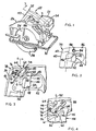
- Fig. 1 is top perspective view of a circular saw having a lockout mechanism embodying the principles of the present invention;
- Fig. 2 is an enlarged, side elevational view of the lockout mechanism shown in Fig. 1, with the lockout mechanism in its "locked" position;
- Fig. 3 is a cross-sectional view taken generally along lines 3-3 of Fig. 1 and showing the lockout mechanism in its "locked" position, parts broken away and shown in cross section to reveal details of construction;
- Fig. 4 is a further enlarged view similar to Fig. 3 showing the latch of the lockout mechanism, and further showing the force vector associated with the switch of the saw, and the arc rotation of a lockout pin of the switch;
- Fig. 5 is a view similar to Fig. 3 but showing the latch mechanism in its "unlocked" position and the trigger switch actuated to the "on" position of the saw;
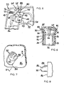
- Fig. 6 is a cross-sectional view taken generally along line 6-6 of Fig. 3;
- Fig. 7 is a top perspective view of a lockout mechanism actuating lever extending from one side of a handle; and
- Fig. 8 is a sectional view taken generally along line 8-8 of Fig. 7 and showing a side profile of the actuating lever.
- Referring to the drawings in greater detail, and initially to Fig. 1, a power circular saw designated generally by the numeral 20 is shown.
Saw 20 has ahousing assembly 22 in which is disposed a motor for powering ablade 24.Blade 24 is generally surrounded by an upperstationary guard 26 and a lowermovable guard 28.Saw 20 also has a generally planar base or shoe 30 attached tostationary guard 26. Base 30 rests on the upper surface of the workpiece as the saw passes therethrough and is used to gauge the depth to whichblade 24 cuts. -
Saw 20 further includes a rear trigger handle 32 and a forward brace handle 34. The trigger handle 32 has apower switch 36 mounted therein for operation by one hand of the saw user. The other hand of the saw user is positioned on brace handle 34 which allows the user to further control the saw as it passes through the workpiece. - Trigger handle 32 has a generally
hollow housing 38 which can be formed in a clamshell fashion byhalf sections 39.Housing 38 has a grippingportion 40 which fits within the palm of an operator during operation, and generally extends in an elongated direction along anaxis 42, as best shown in Fig. 2.Power switch 36 is received withinhousing 38 and has atrigger 44 extending through anaperture 48 formed withinhousing 38 that allows actuation of the trigger by the index finger of an operator. More specifically, trigger 44 is configured with a finger-engagingsurface 45 that accommodates the index finger of the hand of the operator gripping the handle.Trigger 44 is pivotally mounted about anaxis 46 that is transverse to the elongated direction ofhandle portion 40 and toaxis 42.Trigger 44 is actuated by an operator utilizing his or her index finger to rotatetrigger 44 to the left in Fig. 5. As this is done, electrical contacts are made withinswitch 36 to connect the power supply of the saw with the saw motor to result in rotation of the blade.Trigger 44 is biased to its "off" position such that to actuate the switch and rotate it aboutaxis 46 an operator must overcome the internal bias withinswitch 36.Trigger 44 can be pivotally mounted withinhousing 38 by a pin, trunnion or other suitable pivotal mounting arrangement. -
Trigger 44 is also received in afinger resting ring 52 extending outwardly fromhandle portion 40 and generally perpendicular toaxis 42.Ring 52 serves to orient the index finger of a saw operator ontrigger 44, and also provides a restingsurface 54 upon which the index finger of a saw user can rest during operation while at the same time actuating the trigger.Ring 52 will help prevent an operator's index finger from slipping off oftrigger 44 during operation because of the containment of the index finger within the aperture formed by the ring. Thus, the upper pivotal nature oftrigger 44 and the positioning of the trigger within afinger support ring 52 provides a true "trigger" type operation which users often find comfortable and advantageous in selectively controlling the saw. -
Trigger 44 generally includes opposed spaced parallel sidewalls orflanges 56 which form alatch receiving space 58 therebetween, as best shown in Figs. 4-6.Trigger 44 has a lockingpin 60 extending betweenflanges 56 at a location withinhousing 38 that is on the opposite side oftrigger 44 from finger-engagingsurface 45.Pin 60 rotates in thearc 61 indicated in Fig. 4 whentrigger 44 is rotated.Pin 60 provides a locking engagement surface or abutment for engaginglatch 62, as will be more fully described below. -
Latch 62 is generally L-shaped in nature and is pivotally mounted withinhousing 38 about an axis orpivot point 64 which is generally transverse to the elongated direction ofhandle portion 40 andaxis 42.Latch 62 is pivotally mounted withinhousing 38 by any suitable means, such as a pivot pin, trunnion or other pivoting arrangement. Extending fromaxis 64 in a generally rearward direction is a locking leg orsegment 66. Disposed on a rearward end of lockingleg 66 is a generally arcuate abutment surface orcutout 68.Cutout 68 is used to engagepin 60 to securetrigger 44 in its locked position, as will be more fully described below.Leg 66 can have an inverted channel shape to reduce the weight associated with the latch member. Positioned on an upper surface 70 of lockingarm 66 are aspring receiving area 72 and aspring maintaining pin 74. As best shown in Figs. 3 and 4, a coil compression spring is positioned aboutpin 74 and onarea 72 and extends fromarm 66 to asuitable receiving area 77 on an upper surface ofhousing 38.Spring 76 is used to biaslatch 62 toward a locked position, as will be more fully described below. - Extending forwardly from
pivot axis 64 is an actuating leg orsegment 78.Leg 78 extends withinhousing 38 to a position that is forwardly ofpivot axis 46 oftrigger 44 along the elongated direction ofportion 40. Located on a forward end ofleg 78 is a lockinglever 80 that extends transversely to the elongated direction ofhandle portion 40. In particular,lever 80 has twooperator engaging sections 82 extending in opposite directions through oppositely disposedapertures 84 formed on thesidewalls 86 ofhousing 38.Segments 82 are the areas that are engaged by an operator to rotatelatch 62 between a locked position, and an unlocked position, as will be more fully described below. Eachsegment 82 oflever 80 has anupper surface 88 that is sloped downwardly in a direction from the front of the saw toward the back of the saw, as best shown in Fig. 3. Still further,surface 88 is curved in a downwardly sloping arcuate fashion away fromsidewall 86 to a lever end 90 (as best shown in Figs. 6-8). - This arcuate curving is in a convex upwardly fashion. It is
surface 88 and this downwardly sloping arcuate orientation fromside wall 86 to end 90 that allows a user to easily slide his or her thumb off of thesegment 82 afterlatch 62 has been actuated to its disengaged position and to position the thumb at a more comfortable location along the side ofhandle housing 38. In particular, assegment 82 is actuated downwardly by the thumb of a user, it is desirable for the thumb to stay as close tosidewall 86 as possible. The sloping nature ofsegment 82 fromside wall 86 to end 90 allows the thumb to slide overend surface 90 and resume its normal gripping position.End 90 is such that it is similar to a partial spherical surface which also aids the slide of the thumb off ofsegment 82. The thumb of the user may move slightly outwardly away fromsidewall 86 as the thumb slides overend 90. However, the slope ofsurface 88, thedistance segment 82 extends beyondsurface 86, and the soft tissue associated with a user's thumb tip may be such that there is no noticeable outward movement of the thumb fromside wall 86. In addition, some users may find it desirable to continue to rest their thumb onsurface 88 during the entire cutting operation. The slopedsurface 88 and its elimination of any sort of sharp edge associated withend 90 allows more user comfort if the user keeps his/her thumb on the segment. - With reference to Figs. 3 and 4, latch 62 is generally shown in a "locked" or "engaged" position. In this position,
cutout 68 engagespin 60 oftrigger 44, and is maintained thereon by the bias incoil spring 76. If a user attempts to rotatetrigger 44 abouttrigger axis 46,latch 62 will prevent such rotation due to the engagement of abuttingpin 60 andabutment cutout 68. An advantageous feature oflatch 62 is the orientation such that the force vector of a user attempting to rotatetrigger 44 atpin 60 extends directly throughlatch pivot axis 64. More specifically, the rotational arc oftrigger 44 atpin 60 is shown in Fig. 4, asreference numeral 61. As a user attempts to rotatetrigger 44 with his or her index finger, the force vector applied by such action will be generally tangential to such a radius of rotation. The force vector applied by rotation is generally indicated by thereference numeral 92 in Fig. 4.Pivot axis 64 oflatch 62 is configured such thatforce vector 92 resulting from attempted actuation oftrigger 44 extends directly throughaxis 64. Therefore, there are no force components being applied to latch 62 other than those directly throughaxis 64. As is apparent, this structure, because there are no other force vectors, helps prevent accidental disengagement oflatch 62 and holds it firmly in its locked position even if substantial pressures are applied to trigger 44 by an operator. - With reference to Fig. 5, latch 62 is rotated to an "unlocked" and "disengaged" position by an operator pushing downwardly on
upper surface 88 of eithersegment 82 to rotateleg 66 generally upwardly so thatcutout 68disengages pin 60. As is apparent, this rotation results in compression ofspring 76, thus applying a downwardly biasing force toarm 66 that must be overcome by additional pressure onsurface 88. Subsequent to or simultaneously with pushing downwardly onsurface 88, a user begins rotation oftrigger 44 using his or her index finger. Astrigger 44 is rotated, pin 60 can pass adjacent alower edge 94 ofarm 60 until such time as electrical contact is made inswitch 36 and the motor ofsaw 20 is actuated. As best shown in Figs. 6-8, the downwardly slopingarcuate surface 88 fromside wall 86 to end 90 allows an operator to easily slide his or her thumb overend 90 afterlatch 62 has been disengaged and thereafter rest comfortably along the side ofhousing 88 for further operation of the saw. The downward rotational direction of actuatingleg 78 coincides with the downward pivot of a thumb, thus making the pivoting action of latch 62 a more natural occurrence for an operator. - After an operator releases from either
surfaces 88,spring 76 will maintain contact betweenpin 60 andlower edge 94. After an operator is done cutting he or she simply releasestrigger 44 and it returns to its "off" position via an internal spring bias. As it reaches its off position, pin 60 will again engagecutout 68 due to the bias ofspring 76, and latch 62 will return automatically to its locked position. In order to reactuatetrigger 44, an operator must again pivotlatch 62 utilizing either ofsegments 82. - The lockout mechanism in the present invention is advantageous for a number of reasons. First of all, the orientation of
pivot point 64 oflatch 62 such thatforce vector 92 oftrigger 44 extends through such latch axis helps ensure that the latch will not accidentally disengage even when subjected to substantial force. - Still further, the location of actuating
segments 82 and their slopedengaging surfaces 88 at a location that is forwardly of the location of the front portion of engaging surface 75 oftrigger 44 ensures that the normal hand orientation, wherein the thumb is typically forward of the index finger during a gripping action, can be attained during the initial cutting operations of the saw, thus preventing unstable and awkward initial cutting operations. The rotational direction oflatch 62 to its unlocked position in the same direction as the downward pivot of a user's thumb further allows easy, comfortable efficient operation by a user. - Additionally, the downwardly sloping arcuate
upper surfaces 88 from sidewalls 86 towardends 90 allow an operator to easily slide the thumb of the gripping hand overend 90 and off oflever 80 once the latch has been actuated. The dualoppositely extending segments 82 on both sides of the housing also allow easy uniform operation by either right-handed or left-handed operators. - Still further, the pivoting actions of both trigger 44 and latch 62 reduce the vulnerability to contamination and increased friction that is oftentimes present when sliding lockout mechanisms are utilized.
- From the foregoing, it will be seen that this invention is one well adapted to attain all the ends and objects hereinabove set forth together with other advantages which are obvious and which are inherent to the structure. It will be understood that certain features and subcombinations are of utility and may be employed without reference to other features and subcombinations, as defined by the claims.
Claims (6)
- A power tool (20) comprising:a housing (22) including an elongated handle (32) having first and second ends, the handle having an internal cavity and opposed top and bottom walls and opposed sidewalls (86) for receiving the hand of a user with the palm on the top wall, the thumb and index finger of the user adjacent the first end of the handle, and the small end finger of the user adjacent the second end of the handle, and an opening (84) formed in at least one of the sidewalls;a motor in the housing;a switch (36) mounted in the handle cavity for actuating the motor,a latch (62) mounted in the handle cavity adjacent to the switch for movement between an engaged position engaging the switch and preventing the switch from being actuated and a disengaged position disengaging the switch and permitting the switch to be actuated, characterised bythe latch having an actuating lever (80) extending through the side wall opening and having an upper position when the latch is in an engaged position and a lower position when the latch is in a disengaged position, andthe lever having a surface (88) engageable by the thumb of a user, the surface sloping downwardly from the side wall having the opening to a distal end of the lever to permit the thumb to slide over the end if the thumb is used to move the latch from the engaged to the disengaged position.
- The power tool of claim 1 wherein:the switch has a first locking abutment (60); andthe latch is located forward of the switch and has a second locking abutment (68) for engaging the first locking abutment when the latch is in the engaged position.
- The power tool of claim 1 or claim 2 wherein the lever extends outwardly beyond both the sidewalls of the handle, the lever having a sloped surface (88) on each side of the handle.
- The power tool according to any one of claims 1-3 wherein the latch member is pivotally mounted to the handle so that the latch pivots between the engaged and disengaged positions.
- The power tool according to any one of claims 1-4 wherein the sloped surface is generally arcuate in nature.
- The power tool according to any one of claims 1-5 wherein the arcuate sloped surface is of a convex upwardly orientation.
Applications Claiming Priority (3)
| Application Number | Priority Date | Filing Date | Title |
|---|---|---|---|
| US133846 | 1998-08-14 | ||
| US09/133,846 US6057518A (en) | 1998-08-14 | 1998-08-14 | Lockout mechanism for power tool |
| EP99306355A EP0982745B1 (en) | 1998-08-14 | 1999-08-11 | Lock out mechanism for power tool |
Related Parent Applications (1)
| Application Number | Title | Priority Date | Filing Date |
|---|---|---|---|
| EP99306355A Division EP0982745B1 (en) | 1998-08-14 | 1999-08-11 | Lock out mechanism for power tool |
Publications (2)
| Publication Number | Publication Date |
|---|---|
| EP1605482A1 EP1605482A1 (en) | 2005-12-14 |
| EP1605482B1 true EP1605482B1 (en) | 2007-10-17 |
Family
ID=22460558
Family Applications (3)
| Application Number | Title | Priority Date | Filing Date |
|---|---|---|---|
| EP05018447A Expired - Lifetime EP1605482B1 (en) | 1998-08-14 | 1999-08-11 | Lockout mechanism for power tool |
| EP99306355A Expired - Lifetime EP0982745B1 (en) | 1998-08-14 | 1999-08-11 | Lock out mechanism for power tool |
| EP06111208A Expired - Lifetime EP1670011B1 (en) | 1998-08-14 | 1999-08-11 | Lockout mechanism for power tool |
Family Applications After (2)
| Application Number | Title | Priority Date | Filing Date |
|---|---|---|---|
| EP99306355A Expired - Lifetime EP0982745B1 (en) | 1998-08-14 | 1999-08-11 | Lock out mechanism for power tool |
| EP06111208A Expired - Lifetime EP1670011B1 (en) | 1998-08-14 | 1999-08-11 | Lockout mechanism for power tool |
Country Status (8)
| Country | Link |
|---|---|
| US (4) | US6057518A (en) |
| EP (3) | EP1605482B1 (en) |
| JP (1) | JP4786774B2 (en) |
| AT (3) | ATE376250T1 (en) |
| DE (3) | DE69933626T2 (en) |
| DK (1) | DK1605482T3 (en) |
| ES (1) | ES2293450T3 (en) |
| PT (1) | PT1605482E (en) |
Families Citing this family (37)
| Publication number | Priority date | Publication date | Assignee | Title |
|---|---|---|---|---|
| US6057518A (en) * | 1998-08-14 | 2000-05-02 | Black & Decker, Inc. | Lockout mechanism for power tool |
| US6091035A (en) * | 1998-08-14 | 2000-07-18 | Black & Decker, Inc. | Lockout mechanism for power tool |
| JP2000233383A (en) * | 1999-02-12 | 2000-08-29 | Makita Corp | Switch mechanism of power tool |
| US6274828B1 (en) * | 2000-02-22 | 2001-08-14 | Defond Manufacturing Limited | On-off switch with off position locking actuator |
| DE10040326A1 (en) * | 2000-08-17 | 2002-02-28 | Hilti Ag | Locking device for hand-held power tools |
| JP3961755B2 (en) * | 2000-09-18 | 2007-08-22 | Idec株式会社 | Grip-type switch device |
| DE20104536U1 (en) * | 2001-03-16 | 2001-05-23 | Stihl Maschf Andreas | Hand-held, portable work tool with thumb supports |
| AU2002324688A1 (en) | 2001-08-10 | 2003-02-24 | Shakti Systems, Inc. | Logic state transition sensor circuit |
| US6653584B1 (en) * | 2002-05-24 | 2003-11-25 | Rexon Co., Ltd. | Successive switch device of a slot cutting machine |
| US6987244B2 (en) * | 2002-07-31 | 2006-01-17 | Illinois Tool Works Inc. | Self-contained locking trigger assembly and systems which incorporate the assembly |
| US6753490B2 (en) * | 2002-10-16 | 2004-06-22 | S-B Power Tool Corporation | Ambidextrous switch lockout system |
| GB2395460B8 (en) * | 2002-11-22 | 2013-02-06 | Bosch Gmbh Robert | Electric hand tool machine |
| US6930262B2 (en) * | 2003-06-30 | 2005-08-16 | Wy Peron Lee | Safety switch box for saw machine |
| EP1589550A1 (en) * | 2004-04-20 | 2005-10-26 | GMCA PTY Ltd | Switch mechanism |
| US7007712B2 (en) * | 2004-05-10 | 2006-03-07 | Gary Anderson | Pneumatic tool lock |
| CA2506876C (en) * | 2004-05-10 | 2012-11-20 | Gary Anderson | Power tool lockdown device |
| US7750509B2 (en) * | 2004-05-10 | 2010-07-06 | Gary Anderson | Power tool lockdown device |
| TWM301736U (en) * | 2006-06-05 | 2006-12-01 | Mobiletron Electronics Co Ltd | Electrical tool |
| DE102006000316A1 (en) * | 2006-06-29 | 2008-01-03 | Hilti Ag | Main handle for e.g. separating or cutting device, has handle for engine switch and actuating unit that releases safety locking unit, where actuating unit is formed by rotatably supported rotary unit at which blocking area is formed |
| US7476821B1 (en) * | 2007-07-24 | 2009-01-13 | Defond Components Limited | Trigger mechanism |
| JP5148297B2 (en) * | 2008-01-10 | 2013-02-20 | 株式会社マキタ | Marnoco |
| GB0812274D0 (en) * | 2008-07-04 | 2008-08-13 | Black & Decker Inc | Switch mechanism for a power cutter |
| US8198560B2 (en) * | 2009-01-09 | 2012-06-12 | Makita Corporation | Switch devices for power tools |
| US8393835B2 (en) * | 2009-06-16 | 2013-03-12 | Robert Bosch Gmbh | Detachable operating handle for a power tool |
| ITTV20090136A1 (en) * | 2009-06-26 | 2010-12-27 | Saccon Srl | MECHANICAL SAFETY DEVICE FOR SELECTIVE UNLOCKING OF A COMMAND LEVER WITH CABLE TIE FOR VEHICULATED EQUIPMENT AND CONTROL LEVER WITH SAFETY DEVICE FOR VEHICULATED EQUIPMENT |
| US8598477B2 (en) | 2009-10-13 | 2013-12-03 | Barton L. Garvin | Universal switch restraint device |
| US8937259B2 (en) | 2009-10-13 | 2015-01-20 | Barton L. Garvin | Universal electrical circuit breaker locking device |
| US9149923B2 (en) | 2010-11-09 | 2015-10-06 | Black & Decker Inc. | Oscillating tools and accessories |
| US8723060B2 (en) * | 2011-12-21 | 2014-05-13 | Robert Bosch Tool Corporation | Method and mechanism for power tool lock-off |
| US8872049B2 (en) | 2012-04-18 | 2014-10-28 | Milwaukee Electric Tool Corporation | Trigger lock-on lock-off mechanism |
| CN105392587B (en) | 2012-12-11 | 2017-09-15 | 罗伯特·博世有限公司 | Annular saw with light-emitting component system |
| US10014128B2 (en) * | 2013-12-17 | 2018-07-03 | Robert Bosch Tool Corporation | Portable power tool with trigger switch, trigger release and lock-on mechanism combination |
| GB2546733B (en) * | 2016-01-22 | 2018-07-04 | Dyson Technology Ltd | Domestic appliance and part thereof |
| US20180093335A1 (en) | 2016-10-04 | 2018-04-05 | Tti (Macao Commercial Offshore) Limited | Trigger lock for a miter saw |
| JP7167490B2 (en) * | 2018-05-31 | 2022-11-09 | 工機ホールディングス株式会社 | Electric tool |
| TWM605270U (en) * | 2020-06-04 | 2020-12-11 | 勞朋企業有限公司 | Safety switch for gas burner |
| TWI745198B (en) * | 2020-12-21 | 2021-11-01 | 力山工業股份有限公司 | Foldable miter saw with safety device |
Family Cites Families (63)
| Publication number | Priority date | Publication date | Assignee | Title |
|---|---|---|---|---|
| US30270A (en) * | 1860-10-02 | Hew-cleaner | ||
| US1929662A (en) * | 1930-08-16 | 1933-10-10 | Wappat Inc | Motor driven tool switch |
| US3194084A (en) * | 1963-01-21 | 1965-07-13 | Black & Decker Mfg Co | Trigger locking means for hand-portable power-operated device |
| US3331406A (en) | 1964-03-03 | 1967-07-18 | Joseph C Christophel | Radial saw |
| US3383943A (en) | 1966-07-08 | 1968-05-21 | Cutler Hammer Inc | All-speed lever lock |
| US3626118A (en) * | 1966-11-14 | 1971-12-07 | Harold R Botefuhr | Radial arm saw with a depressible key for unlocking a switch-actuating trigger |
| US3422296A (en) | 1967-01-03 | 1969-01-14 | Emerson Electric Co | Interlock reversing switch |
| US3461556A (en) * | 1967-07-10 | 1969-08-19 | Sunbeam Corp | Trigger switch for electric appliance |
| US3376402A (en) | 1967-09-25 | 1968-04-02 | Black & Decker Mfg Co | Reversible electric switch with laterally extending reversing member for use in portable electric tool or appliance |
| US3579002A (en) | 1970-03-31 | 1971-05-18 | Black & Decker Mfg Co | Reversing switch for power tools |
| US3746815A (en) | 1971-11-03 | 1973-07-17 | Cutler Hammer Inc | Off locking trigger switches |
| US3780246A (en) * | 1972-08-22 | 1973-12-18 | Black & Decker Mfg Co | Hand-operated tool with switch actuator having three-position lock-off assembly |
| DE2254554C3 (en) | 1972-11-08 | 1979-08-30 | Licentia Patent-Verwaltungs-Gmbh, 6000 Frankfurt | On-switch for an electric motor-driven hand machine tool |
| USRE30270E (en) | 1972-12-18 | 1980-05-06 | Eaton Corporation | Off locking in-line trigger switch |
| DE7321450U (en) | 1973-06-08 | 1973-09-06 | Metabowerke Kg | Switch for a hand tool operated by an electric motor |
| US3873796A (en) * | 1973-07-06 | 1975-03-25 | Black & Decker Mfg Co | Trigger mechanism for hand-operated power device including independently operable locking devices providing automatic lock off and manual lock-on operation |
| JPS5078998A (en) * | 1973-11-15 | 1975-06-27 | ||
| US3973179A (en) * | 1974-08-23 | 1976-08-03 | The Black And Decker Manufacturing Company | Modular cordless tools |
| US3952239A (en) * | 1974-08-23 | 1976-04-20 | The Black And Decker Manufacturing Company | Modular cordless tools |
| US3971906A (en) * | 1974-11-01 | 1976-07-27 | Lucerne Products, Inc. | Trigger-lock control |
| DE2601269A1 (en) | 1976-01-15 | 1977-07-21 | Streicher Emide Metall | HOUSEHOLD CUTTER |
| US4122320A (en) * | 1976-08-16 | 1978-10-24 | Disston, Inc. | Hand-operated double-acting trigger switch |
| US4135068A (en) | 1976-09-13 | 1979-01-16 | Bowen Tools, Inc. | Dead man safety assembly |
| JPS567053Y2 (en) | 1977-11-15 | 1981-02-16 | ||
| US4196343A (en) * | 1978-03-02 | 1980-04-01 | C.A.H., Inc. | Hair dryer |
| FR2454171A1 (en) | 1979-04-13 | 1980-11-07 | Telemecanique Electrique | LOCKING DEVICE FOR TWO PUSH BUTTONS |
| DE3007304A1 (en) | 1980-02-27 | 1981-09-03 | Marquardt Gmbh, 7201 Rietheim-Weilheim | Switch for electric hand tool - has actuating member rotatably mounted on intermediate member and movable against return spring force and actuating switching mechanism |
| US4276459A (en) * | 1980-06-16 | 1981-06-30 | Ingersoll-Rand Company | Paddle switch safety button |
| DE3173142D1 (en) * | 1980-09-15 | 1986-01-16 | Black & Decker Inc | Safety arrangement for a powered tool or implement |
| US4365141A (en) * | 1981-01-05 | 1982-12-21 | Jerdon Industries, Inc. | Hair dryer |
| DE3104733C3 (en) | 1981-02-11 | 1997-01-09 | Reich Maschf Gmbh Karl | Power tool switches |
| DE3342412A1 (en) | 1983-11-24 | 1985-06-05 | Black & Decker Inc., Newark, Del. | SWITCH ARRANGEMENT FOR THE DIRECTION OF SWITCHING OF AN ELECTRIC TOOL, ESPECIALLY A DRILLING OR IMPACT DRILLING MACHINE |
| DE3731079A1 (en) | 1987-09-16 | 1989-03-30 | Metabowerke Kg | ELECTRIC HAND TOOL WITH A UNIVERSAL MOTOR WITH RIGHT AND LEFT ROTATION |
| US4934494A (en) * | 1988-03-30 | 1990-06-19 | Makita Electric Works, Ltd. | Combined locking mechanism and switch especially for power tools |
| US4864083A (en) | 1988-04-15 | 1989-09-05 | Lucerne Products, Inc. | Reversing switch |
| US4900881A (en) | 1988-10-24 | 1990-02-13 | Breuer Electric Mfg. Co. | Safety interlock for floor maintenance machine and method |
| JPH02137723U (en) | 1989-04-21 | 1990-11-16 | ||
| JPH0832396B2 (en) * | 1989-05-17 | 1996-03-29 | 株式会社マキタ | Portable power tools |
| DE8908924U1 (en) | 1989-07-22 | 1989-09-14 | Gardena Kress + Kastner Gmbh, 7900 Ulm, De | |
| DE4007030A1 (en) * | 1990-03-02 | 1991-09-05 | Black & Decker Inc | POWER-DRIVEN MACHINE TOOL WITH A ROTATING DRIVE |
| DE4023101A1 (en) * | 1990-07-20 | 1992-01-23 | Metabowerke Kg | Electrical power tool - has switch interlock mechanism to ensure safe operation of unit |
| DE4120874C2 (en) | 1991-06-21 | 2002-02-07 | Stihl Maschf Andreas | Device housing for an implement, in particular a chain saw |
| US5310259A (en) | 1993-02-02 | 1994-05-10 | Black & Decker Inc. | Mixer with lockout device for power boost switch |
| DE4309033C2 (en) | 1993-03-20 | 1999-11-25 | Braun Gmbh | Safety switching device for electrical devices |
| US5440089A (en) | 1993-05-07 | 1995-08-08 | General Binding Corporation | Foot/table switch lockout for electric punches |
| DE4407418C2 (en) * | 1994-03-03 | 1998-02-19 | Black & Decker Inc | Switch arrangement, especially for a router |
| JP3572665B2 (en) * | 1994-06-10 | 2004-10-06 | 日立工機株式会社 | Portable power tools |
| DE19522218B4 (en) | 1994-06-23 | 2010-11-11 | Fa. Andreas Stihl | Handle assembly for a motor chain saw |
| US5629679A (en) * | 1994-12-15 | 1997-05-13 | Cranford; Richard | Personal security device |
| US5483727A (en) * | 1995-03-02 | 1996-01-16 | P&F Brother Industrial Corporation | Operating handle for a cutting device |
| JP2852217B2 (en) | 1995-10-26 | 1999-01-27 | リョービ株式会社 | Trigger switch |
| US5577600A (en) * | 1995-11-21 | 1996-11-26 | Emerson Electric Co. | Switch lock-out device for power tool |
| GB9524333D0 (en) | 1995-11-28 | 1996-01-31 | Black & Decker Inc | Lock-on, lock-off switch |
| DE19546328B4 (en) | 1995-12-12 | 2007-12-13 | Robert Bosch Gmbh | Hand tool machine with a rotatable handle |
| JP2977076B2 (en) * | 1996-03-01 | 1999-11-10 | リョービ株式会社 | Power tool switch mechanism |
| US5638945A (en) * | 1996-06-10 | 1997-06-17 | Ryobi North America, Inc. | Locking trigger mechanism for a portable power tool |
| DE19745100B4 (en) | 1996-10-22 | 2007-01-04 | Marquardt Gmbh | Electric switch |
| US5778747A (en) | 1996-11-21 | 1998-07-14 | Rexon Industrial Corp., Ltd. | Power saw having an ergonomically-designed handle and safety switch |
| JPH11347968A (en) * | 1998-06-09 | 1999-12-21 | Makita Corp | Switch mechanism of power tool |
| US5969312A (en) | 1998-06-24 | 1999-10-19 | S-B Power Tool Company | Ambidextrous powers-switch lock-out mechanism |
| US6091035A (en) * | 1998-08-14 | 2000-07-18 | Black & Decker, Inc. | Lockout mechanism for power tool |
| US6057518A (en) * | 1998-08-14 | 2000-05-02 | Black & Decker, Inc. | Lockout mechanism for power tool |
| JP2000233383A (en) * | 1999-02-12 | 2000-08-29 | Makita Corp | Switch mechanism of power tool |
-
1998
- 1998-08-14 US US09/133,846 patent/US6057518A/en not_active Expired - Lifetime
-
1999
- 1999-08-11 ES ES05018447T patent/ES2293450T3/en not_active Expired - Lifetime
- 1999-08-11 EP EP05018447A patent/EP1605482B1/en not_active Expired - Lifetime
- 1999-08-11 DE DE69933626T patent/DE69933626T2/en not_active Expired - Lifetime
- 1999-08-11 AT AT05018447T patent/ATE376250T1/en not_active IP Right Cessation
- 1999-08-11 PT PT05018447T patent/PT1605482E/en unknown
- 1999-08-11 DK DK05018447T patent/DK1605482T3/en active
- 1999-08-11 DE DE69937377T patent/DE69937377T2/en not_active Expired - Lifetime
- 1999-08-11 AT AT06111208T patent/ATE410778T1/en not_active IP Right Cessation
- 1999-08-11 EP EP99306355A patent/EP0982745B1/en not_active Expired - Lifetime
- 1999-08-11 EP EP06111208A patent/EP1670011B1/en not_active Expired - Lifetime
- 1999-08-11 DE DE69939718T patent/DE69939718D1/en not_active Expired - Lifetime
- 1999-08-11 AT AT99306355T patent/ATE343214T1/en not_active IP Right Cessation
- 1999-08-16 JP JP23002199A patent/JP4786774B2/en not_active Expired - Fee Related
-
2000
- 2000-03-14 US US09/524,867 patent/US6340802B1/en not_active Expired - Lifetime
-
2002
- 2002-01-18 US US10/051,422 patent/US6538218B2/en not_active Expired - Fee Related
-
2003
- 2003-03-04 US US10/379,120 patent/US6861598B2/en not_active Expired - Fee Related
Also Published As
| Publication number | Publication date |
|---|---|
| EP1670011A1 (en) | 2006-06-14 |
| EP0982745A2 (en) | 2000-03-01 |
| ATE376250T1 (en) | 2007-11-15 |
| US20020056618A1 (en) | 2002-05-16 |
| JP2000061867A (en) | 2000-02-29 |
| ES2293450T3 (en) | 2008-03-16 |
| US20030136652A1 (en) | 2003-07-24 |
| US6538218B2 (en) | 2003-03-25 |
| US6340802B1 (en) | 2002-01-22 |
| EP1670011B1 (en) | 2008-10-08 |
| PT1605482E (en) | 2008-01-28 |
| EP1605482A1 (en) | 2005-12-14 |
| EP0982745A3 (en) | 2000-08-16 |
| DE69937377T2 (en) | 2008-07-17 |
| ATE343214T1 (en) | 2006-11-15 |
| US6057518A (en) | 2000-05-02 |
| JP4786774B2 (en) | 2011-10-05 |
| ATE410778T1 (en) | 2008-10-15 |
| DK1605482T3 (en) | 2008-02-11 |
| DE69939718D1 (en) | 2008-11-20 |
| DE69933626T2 (en) | 2007-08-23 |
| DE69933626D1 (en) | 2006-11-30 |
| US6861598B2 (en) | 2005-03-01 |
| DE69937377D1 (en) | 2007-11-29 |
| EP0982745B1 (en) | 2006-10-18 |
Similar Documents
| Publication | Publication Date | Title |
|---|---|---|
| EP1605482B1 (en) | Lockout mechanism for power tool | |
| US6288350B1 (en) | Lockout mechanism for power tool | |
| US5638945A (en) | Locking trigger mechanism for a portable power tool | |
| US7739799B2 (en) | Combination utility and sporting knife | |
| EP2248413B1 (en) | Hedgetrimmer with rotatable rear handle | |
| US5577600A (en) | Switch lock-out device for power tool | |
| EP2285535B1 (en) | Powered device having an on-off mechanism | |
| US8723060B2 (en) | Method and mechanism for power tool lock-off | |
| US6610946B2 (en) | Actuation mechanism for a power tool | |
| US6805208B2 (en) | Switch lock-off mechanism for power tools | |
| US7015409B2 (en) | Power tool trigger | |
| US11642771B2 (en) | Operating device with handle and motorized working apparatus | |
| JPH1124771A (en) | Operation lever device of operating machine | |
| EP1079956A1 (en) | Folding knife |
Legal Events
| Date | Code | Title | Description |
|---|---|---|---|
| PUAI | Public reference made under article 153(3) epc to a published international application that has entered the european phase |
Free format text: ORIGINAL CODE: 0009012 |
|
| 17P | Request for examination filed |
Effective date: 20050825 |
|
| AC | Divisional application: reference to earlier application |
Ref document number: 0982745 Country of ref document: EP Kind code of ref document: P |
|
| AK | Designated contracting states |
Kind code of ref document: A1 Designated state(s): AT BE CH CY DE DK ES FI FR GB GR IE IT LI LU MC NL PT SE |
|
| AKX | Designation fees paid |
Designated state(s): AT BE CH CY DE DK ES FI FR GB GR IE IT LI LU MC NL PT SE |
|
| GRAP | Despatch of communication of intention to grant a patent |
Free format text: ORIGINAL CODE: EPIDOSNIGR1 |
|
| GRAS | Grant fee paid |
Free format text: ORIGINAL CODE: EPIDOSNIGR3 |
|
| GRAA | (expected) grant |
Free format text: ORIGINAL CODE: 0009210 |
|
| AC | Divisional application: reference to earlier application |
Ref document number: 0982745 Country of ref document: EP Kind code of ref document: P |
|
| AK | Designated contracting states |
Kind code of ref document: B1 Designated state(s): AT BE CH CY DE DK ES FI FR GB GR IE IT LI LU MC NL PT SE |
|
| REG | Reference to a national code |
Ref country code: GB Ref legal event code: FG4D |
|
| REG | Reference to a national code |
Ref country code: CH Ref legal event code: EP |
|
| REG | Reference to a national code |
Ref country code: IE Ref legal event code: FG4D |
|
| REF | Corresponds to: |
Ref document number: 69937377 Country of ref document: DE Date of ref document: 20071129 Kind code of ref document: P |
|
| REG | Reference to a national code |
Ref country code: PT Ref legal event code: SC4A Free format text: AVAILABILITY OF NATIONAL TRANSLATION Effective date: 20080117 |
|
| REG | Reference to a national code |
Ref country code: SE Ref legal event code: TRGR |
|
| REG | Reference to a national code |
Ref country code: DK Ref legal event code: T3 |
|
| REG | Reference to a national code |
Ref country code: CH Ref legal event code: NV Representative=s name: E. BLUM & CO. AG PATENT- UND MARKENANWAELTE VSP |
|
| REG | Reference to a national code |
Ref country code: ES Ref legal event code: FG2A Ref document number: 2293450 Country of ref document: ES Kind code of ref document: T3 |
|
| ET | Fr: translation filed | ||
| PLBE | No opposition filed within time limit |
Free format text: ORIGINAL CODE: 0009261 |
|
| STAA | Information on the status of an ep patent application or granted ep patent |
Free format text: STATUS: NO OPPOSITION FILED WITHIN TIME LIMIT |
|
| 26N | No opposition filed |
Effective date: 20080718 |
|
| PGFP | Annual fee paid to national office [announced via postgrant information from national office to epo] |
Ref country code: CH Payment date: 20080825 Year of fee payment: 10 Ref country code: ES Payment date: 20080826 Year of fee payment: 10 Ref country code: NL Payment date: 20080824 Year of fee payment: 10 |
|
| PGFP | Annual fee paid to national office [announced via postgrant information from national office to epo] |
Ref country code: AT Payment date: 20080721 Year of fee payment: 10 |
|
| PG25 | Lapsed in a contracting state [announced via postgrant information from national office to epo] |
Ref country code: GR Free format text: LAPSE BECAUSE OF FAILURE TO SUBMIT A TRANSLATION OF THE DESCRIPTION OR TO PAY THE FEE WITHIN THE PRESCRIBED TIME-LIMIT Effective date: 20080118 |
|
| PG25 | Lapsed in a contracting state [announced via postgrant information from national office to epo] |
Ref country code: MC Free format text: LAPSE BECAUSE OF NON-PAYMENT OF DUE FEES Effective date: 20080831 |
|
| PG25 | Lapsed in a contracting state [announced via postgrant information from national office to epo] |
Ref country code: IE Free format text: LAPSE BECAUSE OF NON-PAYMENT OF DUE FEES Effective date: 20080811 Ref country code: CY Free format text: LAPSE BECAUSE OF FAILURE TO SUBMIT A TRANSLATION OF THE DESCRIPTION OR TO PAY THE FEE WITHIN THE PRESCRIBED TIME-LIMIT Effective date: 20071017 |
|
| REG | Reference to a national code |
Ref country code: CH Ref legal event code: PL Ref country code: NL Ref legal event code: V1 Effective date: 20100301 |
|
| PG25 | Lapsed in a contracting state [announced via postgrant information from national office to epo] |
Ref country code: LI Free format text: LAPSE BECAUSE OF NON-PAYMENT OF DUE FEES Effective date: 20090831 Ref country code: CH Free format text: LAPSE BECAUSE OF NON-PAYMENT OF DUE FEES Effective date: 20090831 |
|
| PG25 | Lapsed in a contracting state [announced via postgrant information from national office to epo] |
Ref country code: AT Free format text: LAPSE BECAUSE OF NON-PAYMENT OF DUE FEES Effective date: 20090811 |
|
| PG25 | Lapsed in a contracting state [announced via postgrant information from national office to epo] |
Ref country code: NL Free format text: LAPSE BECAUSE OF NON-PAYMENT OF DUE FEES Effective date: 20100301 Ref country code: LU Free format text: LAPSE BECAUSE OF NON-PAYMENT OF DUE FEES Effective date: 20080811 |
|
| REG | Reference to a national code |
Ref country code: ES Ref legal event code: FD2A Effective date: 20090812 |
|
| PG25 | Lapsed in a contracting state [announced via postgrant information from national office to epo] |
Ref country code: ES Free format text: LAPSE BECAUSE OF NON-PAYMENT OF DUE FEES Effective date: 20090812 |
|
| PGFP | Annual fee paid to national office [announced via postgrant information from national office to epo] |
Ref country code: DK Payment date: 20110826 Year of fee payment: 13 |
|
| PGFP | Annual fee paid to national office [announced via postgrant information from national office to epo] |
Ref country code: GB Payment date: 20120828 Year of fee payment: 14 Ref country code: FI Payment date: 20120829 Year of fee payment: 14 Ref country code: SE Payment date: 20120829 Year of fee payment: 14 |
|
| PGFP | Annual fee paid to national office [announced via postgrant information from national office to epo] |
Ref country code: IT Payment date: 20120823 Year of fee payment: 14 Ref country code: FR Payment date: 20120830 Year of fee payment: 14 Ref country code: BE Payment date: 20120827 Year of fee payment: 14 |
|
| PGFP | Annual fee paid to national office [announced via postgrant information from national office to epo] |
Ref country code: PT Payment date: 20120213 Year of fee payment: 14 |
|
| PGFP | Annual fee paid to national office [announced via postgrant information from national office to epo] |
Ref country code: DE Payment date: 20130828 Year of fee payment: 15 |
|
| REG | Reference to a national code |
Ref country code: PT Ref legal event code: MM4A Free format text: LAPSE DUE TO NON-PAYMENT OF FEES Effective date: 20140211 |
|
| BERE | Be: lapsed |
Owner name: BLACK & DECKER INC. Effective date: 20130831 |
|
| REG | Reference to a national code |
Ref country code: DK Ref legal event code: EBP Effective date: 20130831 |
|
| REG | Reference to a national code |
Ref country code: SE Ref legal event code: EUG |
|
| GBPC | Gb: european patent ceased through non-payment of renewal fee |
Effective date: 20130811 |
|
| PG25 | Lapsed in a contracting state [announced via postgrant information from national office to epo] |
Ref country code: SE Free format text: LAPSE BECAUSE OF NON-PAYMENT OF DUE FEES Effective date: 20130812 Ref country code: FI Free format text: LAPSE BECAUSE OF NON-PAYMENT OF DUE FEES Effective date: 20130811 |
|
| REG | Reference to a national code |
Ref country code: FR Ref legal event code: ST Effective date: 20140430 |
|
| PG25 | Lapsed in a contracting state [announced via postgrant information from national office to epo] |
Ref country code: IT Free format text: LAPSE BECAUSE OF NON-PAYMENT OF DUE FEES Effective date: 20130811 Ref country code: BE Free format text: LAPSE BECAUSE OF NON-PAYMENT OF DUE FEES Effective date: 20130831 |
|
| PG25 | Lapsed in a contracting state [announced via postgrant information from national office to epo] |
Ref country code: PT Free format text: LAPSE BECAUSE OF NON-PAYMENT OF DUE FEES Effective date: 20140211 |
|
| PG25 | Lapsed in a contracting state [announced via postgrant information from national office to epo] |
Ref country code: GB Free format text: LAPSE BECAUSE OF NON-PAYMENT OF DUE FEES Effective date: 20130811 |
|
| PG25 | Lapsed in a contracting state [announced via postgrant information from national office to epo] |
Ref country code: FR Free format text: LAPSE BECAUSE OF NON-PAYMENT OF DUE FEES Effective date: 20130902 |
|
| PG25 | Lapsed in a contracting state [announced via postgrant information from national office to epo] |
Ref country code: DK Free format text: LAPSE BECAUSE OF NON-PAYMENT OF DUE FEES Effective date: 20130831 |
|
| REG | Reference to a national code |
Ref country code: DE Ref legal event code: R119 Ref document number: 69937377 Country of ref document: DE |
|
| REG | Reference to a national code |
Ref country code: DE Ref legal event code: R119 Ref document number: 69937377 Country of ref document: DE Effective date: 20150303 |
|
| PG25 | Lapsed in a contracting state [announced via postgrant information from national office to epo] |
Ref country code: DE Free format text: LAPSE BECAUSE OF NON-PAYMENT OF DUE FEES Effective date: 20150303 |