EP1599343B1 - Printing system and method and computer program product comprising print data integrity monitoring - Google Patents
Printing system and method and computer program product comprising print data integrity monitoring Download PDFInfo
- Publication number
- EP1599343B1 EP1599343B1 EP04713534.8A EP04713534A EP1599343B1 EP 1599343 B1 EP1599343 B1 EP 1599343B1 EP 04713534 A EP04713534 A EP 04713534A EP 1599343 B1 EP1599343 B1 EP 1599343B1
- Authority
- EP
- European Patent Office
- Prior art keywords
- control
- numbers
- printed
- printing
- page
- Prior art date
- Legal status (The legal status is an assumption and is not a legal conclusion. Google has not performed a legal analysis and makes no representation as to the accuracy of the status listed.)
- Expired - Lifetime
Links
- 238000000034 method Methods 0.000 title claims description 181
- 238000012544 monitoring process Methods 0.000 title claims description 34
- 238000004590 computer program Methods 0.000 title claims description 4
- 230000008569 process Effects 0.000 claims description 59
- 238000005520 cutting process Methods 0.000 claims description 11
- 238000004364 calculation method Methods 0.000 claims description 7
- 238000012545 processing Methods 0.000 claims description 7
- 230000005540 biological transmission Effects 0.000 claims description 6
- 238000004080 punching Methods 0.000 claims description 4
- 230000002441 reversible effect Effects 0.000 claims description 3
- 230000000875 corresponding effect Effects 0.000 description 24
- 238000012806 monitoring device Methods 0.000 description 23
- 238000004422 calculation algorithm Methods 0.000 description 14
- 238000004519 manufacturing process Methods 0.000 description 10
- 238000011156 evaluation Methods 0.000 description 5
- 230000006870 function Effects 0.000 description 5
- 238000012805 post-processing Methods 0.000 description 5
- 239000000047 product Substances 0.000 description 5
- 230000007704 transition Effects 0.000 description 4
- 230000001360 synchronised effect Effects 0.000 description 3
- 230000001174 ascending effect Effects 0.000 description 2
- 230000008901 benefit Effects 0.000 description 2
- 239000003086 colorant Substances 0.000 description 2
- 230000001276 controlling effect Effects 0.000 description 2
- 238000007796 conventional method Methods 0.000 description 2
- 230000002950 deficient Effects 0.000 description 2
- 238000012546 transfer Methods 0.000 description 2
- 230000001960 triggered effect Effects 0.000 description 2
- 239000000853 adhesive Substances 0.000 description 1
- 230000001070 adhesive effect Effects 0.000 description 1
- 238000004458 analytical method Methods 0.000 description 1
- 229910002056 binary alloy Inorganic materials 0.000 description 1
- 239000007795 chemical reaction product Substances 0.000 description 1
- 230000002596 correlated effect Effects 0.000 description 1
- 230000000694 effects Effects 0.000 description 1
- 230000001788 irregular Effects 0.000 description 1
- 239000000463 material Substances 0.000 description 1
- 230000003287 optical effect Effects 0.000 description 1
- 238000012552 review Methods 0.000 description 1
- 238000005070 sampling Methods 0.000 description 1
- 230000001953 sensory effect Effects 0.000 description 1
- 230000002123 temporal effect Effects 0.000 description 1
- 230000009466 transformation Effects 0.000 description 1
Images


Classifications
-
- B—PERFORMING OPERATIONS; TRANSPORTING
- B42—BOOKBINDING; ALBUMS; FILES; SPECIAL PRINTED MATTER
- B42C—BOOKBINDING
- B42C19/00—Multi-step processes for making books
-
- B—PERFORMING OPERATIONS; TRANSPORTING
- B41—PRINTING; LINING MACHINES; TYPEWRITERS; STAMPS
- B41J—TYPEWRITERS; SELECTIVE PRINTING MECHANISMS, i.e. MECHANISMS PRINTING OTHERWISE THAN FROM A FORME; CORRECTION OF TYPOGRAPHICAL ERRORS
- B41J29/00—Details of, or accessories for, typewriters or selective printing mechanisms not otherwise provided for
- B41J29/38—Drives, motors, controls or automatic cut-off devices for the entire printing mechanism
- B41J29/393—Devices for controlling or analysing the entire machine ; Controlling or analysing mechanical parameters involving printing of test patterns
-
- B—PERFORMING OPERATIONS; TRANSPORTING
- B41—PRINTING; LINING MACHINES; TYPEWRITERS; STAMPS
- B41J—TYPEWRITERS; SELECTIVE PRINTING MECHANISMS, i.e. MECHANISMS PRINTING OTHERWISE THAN FROM A FORME; CORRECTION OF TYPOGRAPHICAL ERRORS
- B41J3/00—Typewriters or selective printing or marking mechanisms characterised by the purpose for which they are constructed
- B41J3/60—Typewriters or selective printing or marking mechanisms characterised by the purpose for which they are constructed for printing on both faces of the printing material
-
- B—PERFORMING OPERATIONS; TRANSPORTING
- B65—CONVEYING; PACKING; STORING; HANDLING THIN OR FILAMENTARY MATERIAL
- B65H—HANDLING THIN OR FILAMENTARY MATERIAL, e.g. SHEETS, WEBS, CABLES
- B65H2301/00—Handling processes for sheets or webs
- B65H2301/50—Auxiliary process performed during handling process
- B65H2301/51—Modifying a characteristic of handled material
- B65H2301/511—Processing surface of handled material upon transport or guiding thereof, e.g. cleaning
- B65H2301/5111—Printing; Marking
-
- B—PERFORMING OPERATIONS; TRANSPORTING
- B65—CONVEYING; PACKING; STORING; HANDLING THIN OR FILAMENTARY MATERIAL
- B65H—HANDLING THIN OR FILAMENTARY MATERIAL, e.g. SHEETS, WEBS, CABLES
- B65H2511/00—Dimensions; Position; Numbers; Identification; Occurrences
- B65H2511/50—Occurence
- B65H2511/51—Presence
- B65H2511/512—Marks, e.g. invisible to the human eye; Patterns
Definitions
- the invention relates to a printing system, and more particularly to a method, a control device and a computer program product for monitoring printed data in a printing system. More particularly, the invention relates to a method of monitoring printed data in a high performance electrographic printing system.
- edge-punched, band-shaped paper as well as paper without edge perforation are used as the recording medium.
- the page numbers of the printed document can be used instead of the bar code. whereby it is possible to dispense with the printing of another control mark in the form of the bar code.
- a disadvantage of the previously known method is that the bar codes used in this case are very large and significantly affect the printed image of a printed page.
- a method for monitoring a high-performance production process for producing printed products is known.
- the sheets to be printed are conveyed in a predetermined direction.
- a picture of the sheet or a section of the printed sheet is detected by means of a camera.
- the process synchronizes individual sections of the manufacturing process and calibrates the position of the sheets in the manufacturing process.
- this method comprises a control device with which an alarm can be triggered if, for example, the sheets are not merged correctly.
- This control function evaluates the image taken by the chamber, in which case a predetermined portion of the printed image or a code, such as a bar code, is read and evaluated.
- the US 4,429,217 describes an apparatus and method for verifying credit cards, inserting credit cards into corresponding card cases, and stacking the card cases as appropriate for inserting the cards in envelopes.
- the cards are typically identified by specific information in the form of alphabetic, numeric or optical indicia (eg, 1-bar code or I-bar code) or information contained on magnetic stripes.
- the initial product may be provided with individual printed markers so that each bound end product has at least one such mark.
- the page number or a sequence of further pages can be added.
- the mark can also represent the end of a particular sequence, which can then be used to monitor whether all necessary sub-products are present.
- the mark is preferably printed in a region which is cut off at the end of the production process.
- the DE 10050 438 C1 discloses a method of synchronizing a plurality of paper-feeding channels of an inserter.
- Each sheet supplied by such a channel contains corresponding data or information identifying the membership of the sheet to a particular group, data identifying the sheet sequence within a group, and additional data indicating whether the sheet is a final or continuous one Sheet of a group.
- These data may be, for example, by means of a bar code, a 2 D code or other suitable coding on the sheets be upset.
- the group sequence number may consist of, for example, a six-digit number sequence and the sheet sequence number of a two-digit number sequence.
- the marking of an ongoing group or the group end can be in the form of a bit. In the case of an error, only one group is affected, which can be sorted out if necessary and supplemented by hand, for example.
- a tandem printing system is in the US-A-4,609,279 described.
- US-A-4,774,524 is for driving such a printing system provided to connect the main control devices of the two printers on the one hand via a host computer on a data control level and on the other hand via a second connection on a device control level.
- From the US B1-6,501,929 It is known to synchronize the printed page sequence in a tandem printing system via an electronic memory.
- a duplex printing system is known in which a control code is generated and printed for a page to be printed and the printed control code is evaluated.
- From the US-B1 6,246,856 is a printing device with two printing units for simultaneously printing the front and back of a web-shaped recording medium known. From the US-B1-.
- the above publications are hereby incorporated by reference into the present specification.
- a method for monitoring a high-performance production process for producing printed products is known.
- the sheets to be printed are conveyed in a predetermined direction.
- a picture of the sheet or a section of the printed sheet is detected by means of a camera.
- the process synchronizes individual sections of the manufacturing process and the position of the Bends calibrated in the manufacturing process.
- this method comprises a control device with which an alarm can be triggered if, for example, the sheets are not merged correctly.
- This control function evaluates the image taken by the camera, in which case a predetermined portion of the printed image or a code, such as a bar code, is read and evaluated.
- the US 5,265,008 relates to a system and a method for carrying out financial transactions by means of fax machines.
- a payment institution issues transaction vouchers to a particular customer, containing in the form of a bar code a series of alphanumeric random characters, each voucher printed with a different set of alphanumeric random characters.
- the party faxes this coupon to a central facility.
- the coupon will be read automatically and the set of alphanumeric characters will determine if this is an original coupon.
- Each coupon can only be used once.
- the individual vouchers of a customer must be used in a predetermined order.
- Each sheet of paper also prints a barcode that is a sequential number in the printing process.
- the barcode is automatically read after ordered workstations by means of a reader and compared with a serial number of the paper sheet. If the number of the barcode matches the serial number of the paper sheet, printing is OK.
- the invention has for its object to provide a method for monitoring printed data in a printing system which is suitable for using smaller codes compared to conventional bar codes, and with which, nevertheless, the page-by-page synchronization of a large print job can be safely monitored. Furthermore, the invention has for its object to provide a printing system for performing the method.
- control numbers are used as control codes which are not contained numerically in a checklist and that the checklist contains more control numbers than the number of counts contains control numbers. Individual control numbers are thus repeatedly included in the checklist. When evaluating the read control numbers, these can be compared in particular with the order of the control numbers of the checklist, with a deviation being assessed as an error.
- a very small number of sets can be used as the set of control numbers, such as a set of numbers consisting of a maximum of 64 numbers, and in particular a set of numbers consisting of a maximum of 16 Numbers, up to a number consisting of only eight, four or even two numbers, and yet it is possible to monitor a large number of pages.
- This is possible because, in contrast to conventional methods, in which each individual control number has a high information capacity, the information is transferred from the control numbers to the checklist in which this information is stored by the order of the individual control numbers. The larger the entropy in the numerical sense of the checklist, the greater the information contained in the checklist.
- a decimal range of, for example, 0 to 99 is printed as a binary number in the form of a bar or bar code as a control mark. These binary numbers comprise seven digits and therefore form a correspondingly long bar or bar code.
- control number is a one-digit binary number, that is, each control number is either "0" or "1".
- the number of counts of the control numbers can thus be limited even to two numbers.
- a number of numbers can be used which comprises not more than 32, in particular not more than 16, or not more than 8 numbers.
- the checklist may be provided either as a stored data list or by a method (algorithm) for generating a consecutive sequence of control numbers. These methods are realized with typically pseudo-random number generators.
- the period with which the control numbers repeat in the checklist is preferably greater than the typical print volume being executed on the printing system or greater than the maximum page number that may fail in a printing problem without being otherwise noted. If the typical print jobs only cover a few to a hundred pages, then a repetition period of 100 control numbers is sufficient. If the print jobs are considerably more extensive, it is expedient to provide correspondingly longer repetition periods. If, however, a few thousand pages are not printed in a large print job, this is also noticeable in other ways without the need for the monitoring system. Therefore, the repetition periods do not have to comprise more than a thousand or a few thousand control numbers. In the context of the invention, it is of course also possible to use longer repetition periods. In particular, if the checklists are generated by means of pseudo-random number generators, the repetition period can be significantly increased.
- This method is characterized in that are used as control codes control numbers that are included in a checklist not numerically ascending or descending sequentially, and in evaluating the read control numbers, the control numbers of each sheet are compared with each other, and in case of a deviation, this as a mistake is judged.
- a complete sequence of n read control numbers is determined and based on this sequence it is determined at which page number of the print job the error has occurred.
- the determination of the page number can be done by means of a decoding table in which all sequences of n-control numbers and the corresponding page numbers are stored.
- it is also possible to determine the page number such that the control numbers are sequentially generated with a certain control number until the complete sequence of read control numbers has been generated, the number of control numbers generated being a measure of the page number.
- page also includes the terms "print image” and "print page”.
- a sheet-shaped recording medium if a sheet-shaped recording medium is used, a sheet can also be understood to mean a web section if a continuous sheet is used or web-shaped recording carrier (fanfold, continous or web-shaped recording carrier) is used, which is first printed in the web-like state and cut in a post-printing processing operation to a single sheet. In the latter procedure, an assignment to the finally generated sheet can already take place during the printing, if the corresponding post-processing operations are clearly defined.
- the method and the device can be designed to monitor the exact page assignment of print data on the print material, the so-called data integrity. This is particularly important in printing devices or printing systems of importance, having a plurality of printing units and in which at least two printing units on the same recording medium and in particular print on a portion of the recording medium, which is associated with an output sheet. As part of the second printing process, the printed bit marks are detected, the reading result is compared with the originally assigned code, and thus the printing process is controlled.
- a web-shaped recording medium can be cut in a later processing step along the area boundaries to the sheet shape.
- a method of monitoring area data integrity in transmitting print data from a data source to a data receiver, wherein the print data is transmitted are sequentially numbered according to an N-digit binary number, where N is a natural number.
- the serial number is used to read a one-digit control code from a checklist and to read the print data of the Transfer area.
- N is a natural number.
- N is a specific sequence of N single-digit control codes is included only once.
- the associated single-digit control code is read in each case in regions and, based on a comparison of the read sequence of single-digit control codes with the code sequences available in the checklist, a decision about the data integrity is automatically made.
- the data integrity in the area-by-area transfer or printing of print data can be checked with a simple, minimal single-digit binary control code.
- the binary control code is not disturbing when transmitting the data because it has so little information content.
- it allows a minimal print image in the form of a simple stroke, which in particular also corresponds to the area boundary, e.g. Page boundary of a document can be printed.
- the printed bar code can still be used as a control mark for processes following the printing process, such as cutting, folding or punching of the recording medium.
- an N-digit read binary number associated with an area is formed and the consecutive numbering is reconstructed and checked therewith; this can be done by determining their position in the checklist and comparing the number associated with that position with the sequential number of the area generated during transmission.
- the N-digit read binary number is assigned to an area whose read control code is contained in the N-digit read binary number and in particular the area whose read.
- the N-digit read binary number is assigned to an area whose read control code is contained in the N-digit read binary number and, in particular, the area whose read control code is at the first or last digit of the N-digit read binary number. On the basis of the comparison result can then be decided automatically whether in the data transmission partially data has been lost.
- the result of the comparison can be used to automatically determine the number of areas where data has been lost.
- a computer or a controller, especially a printer may be used as the data source.
- a data receiver a controller, a printing unit, each of which prints the single-digit binary control code as a bit mark on a region of the recording medium and / or in particular a recording medium as a carrier of the printed information including the control code.
- the printed bit marks can be read with a sensor and the reading result compared with the control code associated with the transmission and thus the printing process can be controlled.
- associated print data of a region eg in form fields of forms or on the front and back of the document
- one or more printing units on the document be verifiable in terms of their data integrity or correct togetherness
- the checklist may also be provided according to the fourth aspect as a stored data list or by means of a method (algorithm) for generating a successive sequence of control numbers, i. both the sending system (data source) and the receiving system (data receiver) may optionally be connected to the checklist as a stored list, e.g. Look-up-table (LUT) or calculate the control numbers of the checklist online with a computer processor.
- algorithm for generating a successive sequence of control numbers, i. both the sending system (data source) and the receiving system (data receiver) may optionally be connected to the checklist as a stored list, e.g. Look-up-table (LUT) or calculate the control numbers of the checklist online with a computer processor.
- the invention also provides devices, printing devices, controllers or computer software that can automatically effect a sequence according to the invention.
- FIG. 1 A printing system for carrying out the method according to the invention is schematically simplified in FIG FIG. 1 shown.
- This printing system has a printer 1, which is preferably a high-performance printer, for printing on a paper web 2.
- the printer 1 is connected via a data line 3 to a computer 4, from which the printer 1 via the data line 3, a print data stream receives.
- the computer 4 is either a server that merely caches or forwards the print data stream or a host to which the print job and the corresponding print data stream are generated.
- the print data stream used is the IPDS (Intelligent Printer Data Stream) print data stream typical for high-performance printers.
- IPDS Intelligent Printer Data Stream
- print data streams in other formats, such as PCL (Print Command Language), PS (Post Script) or AFP (Advanced Function Presentation).
- the data line 3 leads to a controller 5, in which the print data contained in the print data stream are processed for a subsequently arranged character generator.
- the character generator 6 generates control signals for driving a printing unit 19 with a photoconductor drum 7, with which the printing data are printed on the paper web 2.
- the character generator 6 and the photoconductive drum 7 constitute a printing unit 19.
- the controller 5 is further connected to a device controller, not shown, which drives the various units of the printing apparatus, e.g. The paper transport, the electrophotography unit, the fuser, etc.
- the controller 5 is connected to a control panel 20, displayed on the system information and can be made via the settings on the printer 1. It may include known means such as a screen (esp. Touch-screen), keyboard and / or mouse, etc.
- the paper web 2 is typically a continuous paper web for high-performance printers. However, there are now also known printers with very high performance, which print on single sheets, in which the application of the method according to the invention is also expedient.
- control numbers are generated and inserted into the print data stream. This will be explained below.
- a sensor 8 for scanning the printed on the paper web 2 control numbers is provided adjacent to the paper web 2. If the control numbers are printed in the form of a bar or bar code, the sensor is a simple photo sensor which detects the brightness differences on the paper web.
- the sensor 8 is connected to a monitoring device 9, which in turn is coupled to a central pressure controller 10.
- the paper web 2 is driven by a conveyor 13 in the conveying direction 14.
- the data stream delivered via data line 3 contains additional information about the print job, such as a print job. Sheet or page numbers that are supplied via a further data line 11 to a monitoring device 9. Alternatively, this additional information can initially only be supplied to the controller 5, which then forwards it to the monitoring device 9 via a further data line 12. The data line 11 can then be omitted. It is also possible in this case that the controller 5 generates the additional information about the print job itself and delivers it to the monitoring device 9 if the computer 4 does not provide such information.
- the control signal (A) is a central start / stop signal with which the beginning and the end of a printing process are marked.
- the control signal is usually generated by the character generator 6 as soon as it receives the information from the controller 5 that sufficient print data prepared for the printing process are available.
- the control signal (B) is a clock signal which predetermines a predetermined clock, which synchronizes all of the am Enabling the printing process and is constantly available.
- the individual devices of the printer 1 can determine on the basis of the start / stop signal (A) and the clock signal (B) when the individual pages or predetermined locations on the pages pass them. Usually there is a delay (C1) at the beginning of a printing process until the leading edge of the first page passes a predetermined location in the printer 1 and the cycle time (C2) of the further pages is usually constant.
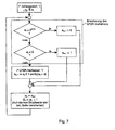
- step S2 the controller 5 reads the printing data coming from the computer 4 via the data line 3.
- a means for generating control numbers is provided, with which the control numbers are provided (step S3).
- This facility can be a list of stored control numbers.
- this device can also be designed as a method. Such methods are, for example, pseudo-random number generators.
- the controller 5 and the monitoring device 9 must synchronize their devices with each other, so that both devices in each case the same Provide a sequence of control numbers.
- Such a synchronization can take place by means of a synchronization command from the controller 5 via the data line 12 to the monitoring device 9.
- This synchronization takes place, for example, after an interruption of the printing process due to an error condition and after the error condition has been remedied.
- An error condition in this sense is also a detected by the monitoring unit 9 error in the printing process.
- the sequence of control numbers should have as low a redundancy as possible, that is to say that sequences with a certain number of control numbers preferably occur only once in the entire list of control numbers. In other words, this means that the entropy should be as large as possible in the numerical order of the control number sequence.
- the sequence of numbers 1, 0, 1, 0, 1, 0 ... has a very high degree of redundancy and a very low entropy, since this sequence repeats with the period two. It is expedient to provide significantly longer repetition periods. For printing systems intended for small print jobs, a repetition period of 100 may already be sufficient. More advantageously, however, larger repetition periods of at least 1000, 10000 or more are to be used.
- control numbers thus generated are inserted in the print data (step S4).
- a character is inserted in each page to be printed at a predetermined location in the print data, which reproduces the control number.
- Such a sign is also called a control mark.
- control numbers a small number of numbers with, for example, sixteen, eight, four or only two numbers corresponding to a few places, for example as a single-digit or two-digit Control numbers are displayed.
- Such control numbers can be printed with a smaller area brand than control numbers from a larger number of numbers.
- control numbers in any number system, such as a hexadecimal, decimal or binary number system.
- control numbers in the binary system.
- the control numbers are preferably represented by bar or bar code, as these are easily detected automatically. In this case, either a thin or thick bar or an existing or a nonexistent bar is provided for each digit of the binary number.
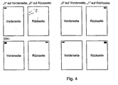
- FIG. 4 shown here in each case the front and back of a sheet is shown, on which the corresponding control numbers are printed in the form of a bar code.
- the bar code is binary in this example, ie only one zero or one is coded. The zero can by no stroke (in the upper sides of the FIG. 4 shown) or by a relatively thin line (in the lower sides of the FIG.
- the one is then coded by a stroke (upper sides) or by a relatively thick stroke (lower sides).
- An advantage of using the variant with different line widths is that on each page to be printed in a given range, a single line can be printed, the downstream of the printing devices such as cutting sensory detected and as a trigger mark for certain actions such as cutting the Record carrier can be used on side transitions.
- the line can be printed in particular along the page boundary at the side transitions of a web-shaped recording medium, whereby it virtually completely disappears after a cutting operation and therefore can no longer be annoying.
- the barcode may also comprise a plurality of dashes and / or for the invention Control numbers of more than one bit represent information content.
- step S5 After inserting the control numbers in the print data they are printed by the printing unit on the paper web 2 (step S5). This completes the process of generating and printing the control numbers (step S6).
- step S7 the control marks or control numbers printed on the paper web 2 are scanned by means of the sensor 8.
- the sampling process is timed by the start / stop signal (A) and the clock signal (B) ( FIG. 2 ) controlled. As a result, exactly predetermined areas can be scanned on the respective printed pages.
- the sensor 8 converts the sampled light signals into digital signals, namely into the control numbers and forwards them to the monitoring device 9.
- the read control number is compared with a corresponding check number of the checklist (step S9).
- the checklist can in turn be stored in the form of a prestored data list in the monitoring device 9 or be generated by means of a predetermined method, such as a pseudo-random number generator. Regardless of how the sequence of control numbers is provided in the monitoring device 9, this sequence of control numbers must be synchronized with the sides to be monitored. This is done in the present embodiment in that the first Assigned control number in the checklist of the first by the start / stop signal (A) and the clock signal (B) side defined and the other control numbers of the list in the order in the checklist assigned to the pages following to the first page in this order with which they are also inserted by the controller 5 in the pages of the print data.
- A start / stop signal
- B clock signal
- step S9 If it is determined in this comparison (step S9) that the read control number should not be the same as the corresponding check number of the checklist, this means that the sensor has scanned a check number which does not correspond to the page which is located at the corresponding position in the Sequence of pages of the printing process should be present. Such a deviation is thus assessed as an error. A corresponding error message is passed on to the print controller 10 (step S10).
- step S11 in which it is checked whether another control number is to be sampled. If this is the case, the process flow returns to step S8, otherwise the process is terminated with step S12.
- step S9 If the comparison in step S9 shows that the read control number is equal to the corresponding check number in the checklist, the method proceeds directly from step S9 to step S11.
- This method can be modified such that not only is it determined whether the correct control number is read by the sensor 8, but it is also determined whether the control number passes exactly at the predetermined time at which it is to pass the sensor, and if there is a time difference, it can be measured, for example in units of the clock signal. By determining this time deviation, the deviation becomes the control number measured from the ideal position on the paper web. As a result, the registration accuracy of the imprint on the paper web can also be determined.
- the information contained in the order of the check numbers present in the checklist is used, the information contained in a check number can be very small. It is therefore even possible to use only a single-digit binary number as a control number. With the invention, the information contained in the control numbers is thus correlated with the information contained in the order of the control number.
- the coefficient k is used for inversion (variation) of the code values.
- the operator " ⁇ " denotes the bitwise exclusive-or-shortcut used to invert the calculated codes. It may be useful, for example, to use a sequence of control numbers for the front side and the corresponding sequence of inverted control numbers for the back side in the case of double-sided printing.
- the method according to the invention can be used very advantageously in a tandem printing system.
- a tandem printing system comprises two printers 1a, 1b (FIG. Fig. 3 ) each having a controller 5a, 5b, a row generator 6a, 6b, printing units, each one a photoconductor drum 7a regarding. 7b, a monitoring device 9a, 9b and a pressure control 10a, 10b.
- the two printers 1a, 1b print on a common paper web 2, wherein the paper web 2 is turned in the area between the two printers 1a, 1b by means of a turning device 15. It is thus printed by each printer 1a, 1b each have a side surface of the paper web, so that the paper web is printed on both side surfaces.
- the two printers 1a and 1b receive the print data stream via a respective data line 3a and 3b from a computer 4.
- the data stream contains additional information about the print job, e.g. Sheet or page numbers, which are also supplied to the monitoring devices 9a and 9b via further data lines 11a and 11b.
- this additional information can initially be supplied only to the controllers 5a and 5b, which then pass them on to the monitoring devices 9a or 9b via further data lines 12a or 12b.
- the data lines 11a and 11b can then be omitted. It is also possible in this case that the controllers 5a and 5b generate the additional information about the print job itself and deliver it to the monitoring devices 9a or 9b if the computer 4 does not provide such information.
- control signal (A) is a central start / stop signal with which the beginning and the end of a printing process are marked.
- the control signal is usually generated by the character generator 6a or 6b as soon as it receives the information from the controller 5a or 5b that the printing process can begin. This is the case in the printer 1a if sufficient print data prepared for the printing process are available in both printers 1a and 1b. In the printer 1b, this is the case when there there are enough print data available and additionally a sufficiently long paper web (supplied by printer 1a) is available for printing.
- the control signal (B) is a clock signal which predetermines a predetermined clock, which enables a temporal synchronization of all devices involved in the printing process and this is constantly available.
- the two printers 1a, 1b each individually and in particular also jointly as a so-called. Single point of operation operated.
- the printer 1a is arranged in the conveying direction (arrow 14) in front of the turning device 15 and similar to the printer 1 from FIG. 1 formed with a sensor 8a.
- the second printer 1b which is arranged in the conveying direction after the turning device 15, has two sensors 8b, 8c, wherein the sensor 8a adjacent to one side of the paper web 2 and the sensor 8c at the same height adjacent to the other side of the paper web 2 is arranged so that both sides of the paper web are scanned by the sensors 8b, 8c.
- the monitoring of the printing process is exactly as in the above-explained in FIG. 1 illustrated printing system.
- both sides of the paper web are monitored.
- control numbers are printed, which have been created for example by means of the same control list, where on one side, the control numbers are not inverted and on the other hand, the control numbers are inverted.
- two control numbers are read out for each paper sheet, one for the front and one for the back.
- the inverted control number is inverted again, so that the two read control numbers can be compared with each other and with the corresponding control number of the control list. If one of these three control numbers deviates one, there is an error and is output accordingly.
- the check list can in turn be provided by a predetermined list of control numbers, which is stored in the two controllers 5a, 5b. However, it can also be generated, for example, in the controller 5a by means of a suitable method and the control numbers can be forwarded via the data line 3 to the controller 5b of the printer 1b. Preferably, however, in the two controllers 5a, 5b, the control numbers are generated by a suitable method, such as a pseudo-random number generator. For this purpose, the random number generator is started with the same start parameters at a corresponding point in time.
- control numbers are passed on and processed by the page-by-side processing of the print data stream.
- control numbers are advanced by the page-by-page scanning of the control codes, which is enabled by the control signals (A) and (B) in synchronism with the printing operation.
- the printed control numbers printed in the form of a bar code can furthermore be used to control other processes which are carried out on the web-shaped recording medium or on the paper web, for example cutting, folding, punching, stapling or adhesive processes.
- a cutting device 16 is arranged, which has two sensors 17 a, 17 b on both sides of the paper web 2 to scan both turned and double-sided record carrier as well as unswept, printed on one side record carrier.
- One of the sensors 17a, 17b detects the printed bar code corresponding to the control code on the paper web 2.
- the scanning signal then controls the time at which the knife 18 of the cutting device cuts the paper web 2 into two parts.
- the blade 18 can be controlled so that it separates the paper web 2 exactly along the stroke. This makes it possible to achieve that the printed line is at the outermost edge of the cut paper or that the line is cut out or punched out and virtually no longer disturbs the paper sheet produced in the process.
- the above embodiment shows how the printing process in two printers of a tandem printing system can be synchronized with one another by means of the method according to the invention.
- a printing process with a post-processing process.
- Such post-processing processes are, for example, the cutting of paper webs, the punching or binding of the printed sheets.
- finishing devices There are a variety of different finishing devices known.
- a monitoring device with a corresponding sensor as used in the above-explained printers, is to be provided in the post-processing device.
- the checklist is provided in the monitoring device and read the control numbers of the sides to be monitored in order to be compared with the corresponding control numbers of the checklist.
- control numbers according to the invention can also be generated with the linear feedback shift register method, which is also referred to as LFSR method ("Linear Feedback Shift Register").
- LFSR method Linear Feedback Shift Register
- bit string can be generated which has the special property that any sequence of n consecutive bits within the entire sequence of N bits always occurs only once.
- the total length N of the bit sequence can be a maximum of 2 n .
- the number sequence is extended by one state: ... ⁇ 2 (n-1) ⁇ 0 ⁇ 1 ⁇ ...
- a sequence of n consecutive bits is understood as a coded page number.
- the coded page number can then be converted into the normal, uncoded page number.
- control numbers of eight consecutive pages give a complete page number.
- Each control number consists of two bits.
- the page numbers run from 1 to 65535.
- the bit sequence of N 65535 bits is traversed twice. In the second pass, the bit positions are offset by one from the first pass, thereby making the second pass distinguishable from the first pass.
- control numbers of five consecutive pages give a complete page number.
- Each control number consists of three bits.
- the page numbers run from 1 to 32768.
- the bit sequence of N 32768 bits is traversed three times.
- t-steps of the LFSR process are executed for each printed page (or printed sheet).
- t bits are supplied for each control number.
- This control number is printed on the paper according to the methods described above and detected by means of a monitoring device.
- the page number of a page is determined by reading the control number from this page as well as the control numbers of the previous pages m-1. The total of m control numbers are then assembled into a coded page number (according to a predetermined order).
- control numbers of the non-existent pages are replaced by defined replacement or initial values that correspond to the end sequence of the bit sequence generated by the LFSR method.
- initial value a the missing control numbers can always be set to 0.
- the method can also be realized in such a way that the control numbers of the "searched" page and the following m-1 pages are assembled. However, then the determination of the page number for the last m-1 pages of a print job is problematic or not possible.
- each page is printed with a control number consisting of one bit each.
- the first read control number is considered the most significant, the last one read as the least significant number.
- the missing control numbers on pages 1 to 15 are assumed to be "0".
- the end sequence of the sequence indicates that these control numbers actually take the value 0.
- a decoding method which supplies the uncoded page number z from the coded page number c.
- a decoding method which supplies the uncoded page number z from the coded page number c.
- the variant with the largest computation time and the smallest memory requirement uses the LFSR method, which is applied "backwards", ie opposite to the (encoding) LFSR method, which generated the control numbers.
- the number of passes d required is then counted until the LFSR method reaches the initial state of the first coded page number C 1 .
- the number of passes d can also be 0.
- the first table is a listing of intermediate values evenly distributed over all coded page numbers.
- the second table contains the information as to whether a particular coded page number c is contained in the first table.
- the second table comprises N bits, that is one bit per possible value c.
- the first table then contains 1024 values or 2048 bytes.
- the second table claims 65536 bits or 8 kbytes. The number of passes d is always in the range of 0 to 63, and within the first table a maximum of 1024 search steps are necessary.
- the LFSR bit sequence (1 to N) is traversed several times during a run of the page numbers (1 to Z).
- the page numbers are virtually "blended" into each other.
- the number of pages at which an error has occurred can thus be determined from the sequence of read control numbers.
- the LFSR method thus represents a preferred pseudo-random number generator, since the resulting sequence of control numbers is suitable for the subsequent determination of the page numbers.
- pseudo-random number generators instead of a pseudo-random number generator, other random number generators can be used.
- random number generators are known that use the thermal noise of a diode to generate the random numbers.
- Corresponding hardware components are commercially available. However, if no pseudo-random number generators but "true random number” generators are used, the relevant sequences of the random numbers must be recorded in the printing system and the monitoring devices made available.
- control numbers of at least n previous pages are stored in order to be able to indicate the earliest possible faulty page number in the event of an error. If the control numbers of the previous pages are not saved, to avoid erroneous printouts, all n previous pages must always be discarded and reprinted in the event of an error.
- the sequence B is the sequence of control numbers read from the printed pages.
- control numbers of the previous page 30 and the current page 31 are the same, i. H. it will be further investigated according to case b).
- the method according to the invention can be modified such that a single read error is tolerated if thereafter the check numbers of at least following pages match again, where i is equal to or greater than 10.
- the memory for the control numbers of the past pages must then include at least 2i numbers to indicate the range of a possible error.
- a page number can be decoded from this. This can be compared with a page number which is obtained, for example, by counting the printed sheets or is obtained by assigning to each check number of the checklist a page number which can then be correspondingly read out. From this comparison can be z. For example, you can see if and how many pages are missing in the printout or are duplicated. This is important for identifying and remedying possible causes of errors.
- Example 2 This example continues Example 2 above.
- This list shows the decoded page numbers after an error.
- the page numbers in column A result from the reference sequence
- the page numbers in column B result from the read control numbers. It turns out that the page numbers of column B over 15 pages are irregular and quasi disturbed, since in the expression one page and thus one bit of the associated page numbers was missing. From the reference page number 46, the page numbers of column B are again regular, and the difference between column B and column A indicates that exactly one page was missing. The assumption mentioned in Example 2 that pages could have been printed several times can thus be excluded. On page 31, where the error is first detected, this information is not yet apparent.
- FIGS. 1 and 3 illustrated printing systems used for logical control and monitoring of the printing process.
- Corresponding data integrity monitoring can also take place in other printing systems, for example in a printing system which has two printing units in a common housing for simultaneously printing the front side and the back side of a web-shaped or sheet-like recording medium, as is known from US Pat US B1-6,246,856 is known.
- bit marks are printed as so-called bit marks on each printed page.
- the bit marks each contain one bit of information, represented e.g. B. by a thin or thick line. Whether a "0" or a "1" is printed as a bit mark is determined by the controller on the basis of the LFSR algorithm already explained above, which is run through for each printed page.
- the LFSR algorithm is based on an N-bit key and generates a unique bit sequence of length 2 N bits. In each case N consecutive bits within the bit sequence are again unique and can therefore be understood as an "encrypted page number".
- N 12
- N 12
- the repetition rate for the page-by-page assignment of the control numbers (page numbers) in this case is 4096 pages.
- each N-digit binary control number exists only once, so there is a one-to-one correspondence between all start and end positions of N-digit sections with their respective position numbers (page numbers) .
- the same LFSR algorithm is used as in the controller.
- a first monitoring step the device controller checks to see if the state values supplied by the controller match the values calculated using its own LFSR algorithm.
- the printed bit marks are scanned with brand sensors.
- the device control evaluates the signals of the brand sensors and decodes the Scanning signals back to individual bits.
- the read bits must match the bits supplied by the LFSR algorithm. Even possible reading errors of the brand sensors can or must be taken into account. It may happen that a bit mark is either not read or misinterpreted. It is advantageous that individual read errors are tolerated within certain limits (eg N pages). A deviation of two or more bits within N pages causes the printing process to be aborted with an error message.
- the "encrypted" page number can be formed from N consecutively read bits and, in turn, a "real", consecutive page number can be decoded therefrom, as described above.
- FIGS. 8 to 11 illustrate a representation in which the generated control codes, the read control codes and any system messages that are generated based on the reading result and / or the comparison of the sequence of control codes and the read control codes are displayed.
- a display in tabular form is provided, which can be called up by the user (operator) at any time, and which is constantly updated during a running printing process.
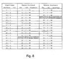
- the first column in the table shows the sequence of the LFSR algorithm with the expected page number and the expected bit mark.
- Threshold values can be set for the evaluation, namely, how many errors of the first or second type may occur before the decision "data integrity error" is automatically made and the printing process is aborted.
- the error of the first kind may occur at most twice per 12 pages before the printing process is aborted, while the second type error may only occur a maximum of once per 12 pages before the printing process is aborted. If a first type error and a second type error occur within 12 pages, printing will continue.
- bit marks of page No. 14 on the lower printing unit and page No. 22 of the upper printing unit are not recognized.
- the missing bit mark can then be replaced by the expected bit mark of the algorithm, so that the page numbers continue to be properly decoded and displayed. The individual read errors are tolerated.
- the unrecognized mark ("mark missing") is marked in the color representation on the control panel with a first color, eg with yellow.
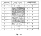
- FIG. 11 The example shown shows the procedure for two or more incorrectly read bit marks.
- the data source bitstream is (first column), starting at page 21 and ending at page 32: 111110111011.
- the lower print engine (right column) has all Data printed correctly and therefore between pages 21 and 32 the same bit string of printed bit marks.
- the bit marks printed correctly by the upper print engine end at page 19.
- a serious bit error occurs: A 1 is read, although a zero would be expected. If you then follow the read bit values until the page number 32 is decoded, it turns out that the above-mentioned bit pattern 111110111011 for the page number 32 already occurs at a position at which the first bit from the (computational) page number 20 (the first error occurred). From this it can be clearly concluded that a page has been lost in the printed page sequence. In the displayed list according to FIG. 11 this is immediately apparent to the viewer, because in the middle column for the upper printing unit, the page numbers from page 31 are shifted upwards by one line compared to the corresponding page numbers of the left column of the data source.
- the invention is described above with reference to examples which print a web-shaped recording medium, in particular a paper web, on one or both sides. However, it can also be used to synchronize differently colored printouts or to check the data integrity of printouts on cut sheets, especially when different data from different print engines are printed on a single cut sheet.
- Data integrity on a record carrier can be accomplished by comparing the control codes between the data source and the data receiver (such as in particular FIG. 8 described) or by comparison between the control codes of two data receivers, in particular, if the two data receivers are printing units or different areas (front / back) of a recording medium, which were printed with different printing units or in separate printing processes.
- control codes of the print data of both areas must be included the same number sequence or a number sequence transformation have been performed.
- Each sheet can print several print images on the front and back and / or in different colors. For full-color printing, for example, up to five (or more) individual color images are printed per sheet page.
- control number can be generated and printed in the form of a control mark.
- the control marks of different print images should not overlap.
- the control numbers of the individual print images do not have to be the same, but can be varied according to a fixed scheme; for example, the control numbers of the back side can be inverted to those of the front side.
- the read control numbers are compared with a reference sequence of control numbers supplied by an electronic circuit, a stored table, a calculation method or a random number generator.
- a missing or multiple printed sheet is recognized.
- control numbers are printed as control code, which are contained in a checklist.
- the control numbers are not sorted numerically in succession, but arranged in an arbitrary order with the highest possible entropy.
- the expression checks whether the control numbers have been printed in the same order as in the checklist. This makes it possible to use control numbers with few digits, in particular even single-digit binary numbers.
- control numbers can either be provided by stored checklists or the checklists can be generated by a corresponding method.
- a preferred method is the LFSR method, since control numbers are generated which are suitable for calculating the page numbers from the control numbers.
Description
Die Erfindung betrifft ein Drucksystem und insbesondere ein Verfahren, eine Steuervorrichtung und ein Computerprogrammprodukt zum Überwachen von gedruckten Daten in einem Drucksystem. Die Erfindung betrifft weiterhin insbesondere ein Verfahren zum Überwachen von gedruckten Daten in einem elektrografischen Hochleistungs-Drucksystem.The invention relates to a printing system, and more particularly to a method, a control device and a computer program product for monitoring printed data in a printing system. More particularly, the invention relates to a method of monitoring printed data in a high performance electrographic printing system.
Bei elektrografischen Hochleistungs-Drucksystemen mit einer Druckleistung von mehr als 40 Seiten pro Minute wird sowohl randgelochtes, bandförmiges Papier als auch Papier ohne Randlochung als Aufzeichnungsträger verwendet.In high-performance electrographic printing systems with a printing performance of more than 40 pages per minute, edge-punched, band-shaped paper as well as paper without edge perforation are used as the recording medium.
Bei Hochleistungs-Drucksystemen ist es notwendig, dass die Druckdaten und der Drucker selbst seitenweise synchronisiert sind. Hierzu ist ein Verfahren bekannt, bei welchem auf jeden bedruckten Bogen zumindest zwei Druckbilder gedruckt werden, wobei jedes Druckbild einen Bar-Code enthält. Diese Bar-Codes enthalten fortlaufende Zahlen. Sie können von einer bestimmten Arbeitsstation, wie zum Beispiel einem weiteren Drucker oder Druckwerk oder einer Nachbearbeitungsstation gelesen werden. Ergeben sich Abweichungen der Bar-Codes innerhalb eines Bogens, so wird dies als Fehler beurteilt.For high-performance printing systems, it is necessary for the print data and the printer itself to be synchronized page by page. For this purpose, a method is known in which at least two printed images are printed on each printed sheet, each printed image containing a bar code. These bar codes contain consecutive numbers. They can be read by a specific workstation, such as another printer or print engine, or a post-processing station. If deviations of the bar codes within an arc occur, then this is judged as an error.
Anstelle des Bar-Codes können auch grundsätzlich die Seitenzahlen des gedruckten Dokumentes verwendet werden, wodurch auf den Aufdruck einer weiteren Kontrollmarke in Form des Bar-Codes verzichtet werden kann.In principle, the page numbers of the printed document can be used instead of the bar code. whereby it is possible to dispense with the printing of another control mark in the form of the bar code.
Jedoch ist es nicht immer möglich, die Seitenzahlen zu verwenden, insbesondere wenn ein großer Druckauftrag aus einer Vielzahl einzelner kurzer Dokumente mit jeweils wenigen Seiten besteht oder wenn die Dokumente keine Seitenzahlen beinhalten. Zudem ist das automatische Abtasten von Seitenzahlen wesentlich aufwendiger als das eines Bar-Codes.However, it is not always possible to use the page numbers, especially if a large print job consists of a large number of individual short documents, each with few pages, or if the documents do not contain page numbers. In addition, the automatic scanning of page numbers is much more complicated than that of a bar code.
Nachteilig an dem bisher bekannten Verfahren ist, dass die hierbei verwendeten Bar-Codes sehr groß sind und das Druckbild einer bedruckten Seite erheblich beeinträchtigen.A disadvantage of the previously known method is that the bar codes used in this case are very large and significantly affect the printed image of a printed page.
Aus der
Aus der
Die
In der
Die
Weiterhin ist es bei sogenannten Tandem-Drucksystemen in der Regel erforderlich, die Druckbilder der beiden Druckgeräte des Tandem-Drucksystems seitengenau zu positionieren. Ein Tandem-Drucksystem ist in der
Aus der
Die
Aus der
Der Erfindung liegt die Aufgabe zugrunde, ein Verfahren zum Überwachen von gedruckten Daten in einem Drucksystem zu schaffen, das zur Verwendung von im Vergleich zu herkömmlichen Bar-Codes kleineren Codes geeignet ist, und mit welchen dennoch die seitenweise Synchronisation eines großen Druckauftrages sicher überwacht werden kann. Ferner liegt der Erfindung die Aufgabe zugrunde, ein Drucksystem zur Durchführung des Verfahrens zu schaffen.The invention has for its object to provide a method for monitoring printed data in a printing system which is suitable for using smaller codes compared to conventional bar codes, and with which, nevertheless, the page-by-page synchronization of a large print job can be safely monitored. Furthermore, the invention has for its object to provide a printing system for performing the method.
Die Aufgabe wird durch die in den unabhängigen Ansprüchen angegebene Erfindung gelöst. Vorteilhafte Ausgestaltungen der Erfindung sind in den jeweiligen Unteransprüchen angegeben.The object is achieved by the invention specified in the independent claims. Advantageous embodiments of the invention are specified in the respective subclaims.
Gemäß einem ersten Aspekt der Erfindung weist ein Verfahren zum Überwachen von gedruckten Daten in einem Drucksystem folgende Schritte auf:
- Erzeugen eines Kontrollcodes für jeweils eine zu druckende Seite,
- Drucken des Kontrollcodes auf die jeweils entsprechende Seite eines zu bedruckenden Aufzeichnungsträgers,
- Automatisches Lesen und Auswerten der gedruckten Kontrollcodes.
- Generating a control code for each one page to be printed,
- Printing the control code on the respective corresponding side of a record carrier to be printed,
- Automatic reading and evaluation of the printed control codes.
Die Erfindung zeichnet sich gemäß diesem Aspekt dadurch aus, dass als Kontrollcodes Kontrollzahlen verwendet werden, die in einer Kontrollliste nicht numerisch aufeinanderfolgend enthalten sind und, dass die Kontrollliste mehr Kontrollzahlen enthält als die Zahlenmenge Kontrollzahlen enthält. Einzelne Kontrollzahlen sind somit wiederholt in der Kontrollliste enthalten. Beim Auswerten der gelesenen Kontrollzahlen können diese insbesondere mit der Reihenfolge der Kontrollzahlen der Kontrollliste verglichen werden, wobei eine Abweichung als Fehler beurteilt wird.According to this aspect, the invention is characterized in that control numbers are used as control codes which are not contained numerically in a checklist and that the checklist contains more control numbers than the number of counts contains control numbers. Individual control numbers are thus repeatedly included in the checklist. When evaluating the read control numbers, these can be compared in particular with the order of the control numbers of the checklist, with a deviation being assessed as an error.
Es ist auch möglich, falls auf einen Bogen zwei oder mehr Kontrollzahlen gedruckt werden, die Auswertung durch Vergleich der Kontrollzahlen des Bogens auszuführen, wobei eine Abweichung als Fehler beurteilt wird.It is also possible, if two or more control numbers are printed on one sheet, to carry out the evaluation by comparing the control numbers of the sheet, with a deviation being judged as an error.
Gemäß einem weiteren vorteilhaften Ausführungsbeispiel der Erfindung wird beim Auswerten der gelesenen Kontrollzahlen deren Reihenfolge mit derjenigen der Kontrollliste verglichen.According to a further advantageous embodiment of the invention, when evaluating the read control numbers their order compared with that of the control list.
Da die Reihenfolge der Kontrollzahlen in der Kontrollliste von einer numerisch aufsteigenden bzw. numerisch absteigenden Reihenfolge abweicht, kann eine sehr kleine Zahlenmenge als Menge der Kontrollzahlen verwendet werden, wie zum Beispiel eine Zahlenmenge bestehend aus maximal 64 Zahlen, und insbesondere eine Zahlenmenge bestehend aus maximal 16 Zahlen, bis hin zu einer aus nur acht, vier oder sogar nur zwei Zahlen bestehenden Zahlenmenge, und dennoch ist es möglich, eine große Anzahl von Seiten zu überwachen. Dies wird dadurch möglich, dass im Gegensatz zu herkömmlichen Verfahren, bei welchen jede einzelne Kontrollzahl eine hohe Informationskapazität besitzt, die Information aus den Kontrollzahlen in die Kontrollliste übertragen wird, in der diese Information durch die Reihenfolge der einzelnen Kontrollzahlen gespeichert ist. Die in der Kontrollliste enthaltene Information ist um so größer, je größer die Entropie im numerischen Sinne der Kontrollliste ist. Bei herkömmlichen Verfahren wird ein Dezimalzahlenbereich von zum Beispiel 0 bis 99 als Binärzahl in Form eines Strich- oder Bar-Codes als Kontrollzahl bzw. Kontrollmarke aufgedruckt. Diese Binärzahlen umfassen sieben Stellen und bilden daher einen dementsprechend langen Bar- oder Strichcode.Since the order of the control numbers in the control list deviates from a numerically ascending or numerically descending order, a very small number of sets can be used as the set of control numbers, such as a set of numbers consisting of a maximum of 64 numbers, and in particular a set of numbers consisting of a maximum of 16 Numbers, up to a number consisting of only eight, four or even two numbers, and yet it is possible to monitor a large number of pages. This is possible because, in contrast to conventional methods, in which each individual control number has a high information capacity, the information is transferred from the control numbers to the checklist in which this information is stored by the order of the individual control numbers. The larger the entropy in the numerical sense of the checklist, the greater the information contained in the checklist. In conventional methods, a decimal range of, for example, 0 to 99 is printed as a binary number in the form of a bar or bar code as a control mark. These binary numbers comprise seven digits and therefore form a correspondingly long bar or bar code.
Die Erfindung erlaubt die Verwendung von ein-, zwei- oder dreistelligen Zahlen. Im Extremfall wird als Kontrollzahl eine einstellige Binärzahl verwendet, d.h., dass jede Kontrollzahl entweder "0" oder "1" ist.The invention allows the use of one, two or three digit numbers. In extreme cases, the control number is a one-digit binary number, that is, each control number is either "0" or "1".
Mit dem erfindungsgemäßen Verfahren kann die Zahlenmenge der Kontrollzahlen somit sogar auf zwei Zahlen beschränkt werden. Mit der Erfindung kann eine Zahlenmenge verwendet werden, die nicht mehr als 32, insbesondere nicht mehr als 16, beziehungsweise nicht mehr als 8 Zahlen umfasst.With the method according to the invention, the number of counts of the control numbers can thus be limited even to two numbers. With the invention, a number of numbers can be used which comprises not more than 32, in particular not more than 16, or not more than 8 numbers.
Die Kontrollliste kann entweder als eine gespeicherte Datenliste oder mittels eines Verfahrens (Algorithmus) zum Erzeugen einer aufeinanderfolgenden Folge von Kontrollzahlen bereit gestellt werden. Diese Verfahren werden mit typischerweise Pseudo-Zufallszahlen-Generatoren realisiert.The checklist may be provided either as a stored data list or by a method (algorithm) for generating a consecutive sequence of control numbers. These methods are realized with typically pseudo-random number generators.
Die Periode, mit welcher sich die Kontrollzahlen in der Kontrollliste wiederholen, ist vorzugsweise größer als das typische Druckvolumen, das am Drucksystem ausgeführt wird oder größer als die maximale Seitenzahl, die bei einem Druckproblem ohne sicher auf andere Weise bemerkt zu werden, ausfallen kann. Umfassen die typischen Druckaufträge lediglich einige bis hundert Seiten, so genügt eine Wiederholungsperiode von 100 Kontrollzahlen. Sind die Druckaufträge wesentlich umfangreicher, so ist es zweckmäßig, entsprechend größere Wiederholungsperioden vorzusehen. Werden jedoch bei einem großen Druckauftrag einige tausend Seiten nicht gedruckt, so fällt dies auch anderweitig auf, ohne dass hierzu das Überwachungssystem notwendig ist. Deshalb müssen die Wiederholperioden grundsätzlich nicht mehr als tausend oder einige tausend Kontrollzahlen umfassen. Im Rahmen der Erfindung ist es selbstverständlich auch möglich, längere Wiederholungsperioden zu verwenden. Insbesondere wenn die Kontrolllisten mittels Pseudo-Zufallszahlen-Generatoren erzeugt werden, kann die Wiederholungsperiode wesentlich gesteigert werden.The period with which the control numbers repeat in the checklist is preferably greater than the typical print volume being executed on the printing system or greater than the maximum page number that may fail in a printing problem without being otherwise noted. If the typical print jobs only cover a few to a hundred pages, then a repetition period of 100 control numbers is sufficient. If the print jobs are considerably more extensive, it is expedient to provide correspondingly longer repetition periods. If, however, a few thousand pages are not printed in a large print job, this is also noticeable in other ways without the need for the monitoring system. Therefore, the repetition periods do not have to comprise more than a thousand or a few thousand control numbers. In the context of the invention, it is of course also possible to use longer repetition periods. In particular, if the checklists are generated by means of pseudo-random number generators, the repetition period can be significantly increased.
Weiterhin kann ein Verfahren zum Überwachen von gedruckten Daten in einem Drucksystem vorgesehen, das folgende Schritte umfasst:
- Erzeugen eines Kontrollcodes für eine jeweils ein zu druckendes Druckbild,
- Drucken von zumindest zwei Druckbildern mit jeweils einem Kontrollcode auf einen zu bedruckenden Bogen,
- automatisches Lesen und Auswerten der gedruckten Kontrollcode.
- Generating a control code for each print image to be printed,
- Print at least two print images, each with a control code on a sheet to be printed,
- automatic reading and evaluation of the printed control code.
Dieses Verfahren zeichnet sich hierdurch aus, dass als Kontrollcodes Kontrollzahlen verwendet werden, die in einer Kontrollliste nicht numerisch aufsteigender bzw. absteigender aufeinanderfolgend enthalten sind, und beim Auswerten der gelesen Kontrollzahlen die Kontrollzahlen jeweils eines Bogens miteinander verglichen werden, und bei einer Abweichung dies als Fehler beurteilt wird.This method is characterized in that are used as control codes control numbers that are included in a checklist not numerically ascending or descending sequentially, and in evaluating the read control numbers, the control numbers of each sheet are compared with each other, and in case of a deviation, this as a mistake is judged.
Nach einem bevorzugten Verfahren der Erfindung wird nach Feststellen eines Fehlers mittels des erfindungsgemäßen Überwachungsverfahrens eine vollständige Sequenz von n gelesenen Kontrollzahlen ermittelt und anhand dieser Sequenz wird festgestellt, bei welcher Seitenzahl des Druckauftrages der Fehler aufgetreten ist. Die Bestimmung der Seitenzahl kann mittels einer Decodierungstabelle erfolgen, in der alle Sequenzen von n-Kontrollzahlen und die korrespondierenden Seitenzahlen gespeichert sind. Es ist jedoch auch möglich, die Seitenzahl derart zu bestimmen, das die Kontrollzahlen ausgehend mit einer bestimmten Kontrollzahl aufeinanderfolgend erzeugt werden, bis die vollständige Sequenz von gelesenen Kontrollzahlen erzeugt worden ist, wobei die Anzahl der erzeugten Kontrollzahlen ein Maß für die Seitenzahl ist.According to a preferred method of the invention, after detecting an error by means of the monitoring method according to the invention, a complete sequence of n read control numbers is determined and based on this sequence it is determined at which page number of the print job the error has occurred. The determination of the page number can be done by means of a decoding table in which all sequences of n-control numbers and the corresponding page numbers are stored. However, it is also possible to determine the page number such that the control numbers are sequentially generated with a certain control number until the complete sequence of read control numbers has been generated, the number of control numbers generated being a measure of the page number.
Der Begriff "Seite" umfasst auch die Begriffe "Druckbild" und "Druckseite". Von einem Bogen im Sinne der vorliegenden Erfindung kann beispielsweise gesprochen werden, wenn ein blattförmiger Aufzeichnungsträger (engl. cut sheet recording carrier) verwendet wird, unter einem Bogen kann aber auch ein Bahnabschnitt verstanden werden, wenn ein kontinuierlicher bzw. bahnförmiger Aufzeichnungsträger (engl. fanfold, continous oder web-shaped recording carrier) verwendet wird, der zunächst im bahnförmigen Zustand bedruckt und in einem dem Bedrucken nachgeschalteten Verarbeitungsvorgang zu einem Einzelblatt geschnitten wird. Bei letzterem Vorgehen kann bereits während dem Drucken eine Zuordnung zu dem letztlich erzeugten Bogen erfolgen, wenn die entsprechenden Nachverarbeitungsvorgänge klar definiert sind.The term "page" also includes the terms "print image" and "print page". For example, if a sheet-shaped recording medium is used, a sheet can also be understood to mean a web section if a continuous sheet is used or web-shaped recording carrier (fanfold, continous or web-shaped recording carrier) is used, which is first printed in the web-like state and cut in a post-printing processing operation to a single sheet. In the latter procedure, an assignment to the finally generated sheet can already take place during the printing, if the corresponding post-processing operations are clearly defined.
Das Verfahren und die Vorrichtung kann zum Überwachen der genauen Seitenzuordnung von Druckdaten auf dem Druckgut, die sogenannte Datenintegrität (data integrity), ausgebildet sein. Diese ist insbesondere in Druckgeräten bzw. Drucksystemen von Bedeutung, die mehrere Druckwerke aufweisen und bei denen mindestens zwei Druckwerke auf denselben Aufzeichnungsträger und insbesondere auf einen Bereich des Aufzeichnungsträgers drucken, der einem Ausgabeblatt zugeordnet ist. Im Zuge des zweiten Druckvorgangs werden die gedruckten Bit-Marken erfasst, das Leseergebnis mit dem ursprünglich zugeordneten Code verglichen und damit der Druckprozess gesteuert.The method and the device can be designed to monitor the exact page assignment of print data on the print material, the so-called data integrity. This is particularly important in printing devices or printing systems of importance, having a plurality of printing units and in which at least two printing units on the same recording medium and in particular print on a portion of the recording medium, which is associated with an output sheet. As part of the second printing process, the printed bit marks are detected, the reading result is compared with the originally assigned code, and thus the printing process is controlled.
Zur Erzeugung des Ausgabeblattes kann insbesondere ein bahnförmiger Aufzeichnungsträger in einem späteren Verarbeitungsschritt entlang der Bereichsgrenzen zur Blattform zugeschnitten werden.To produce the output sheet, in particular a web-shaped recording medium can be cut in a later processing step along the area boundaries to the sheet shape.
Gemäß einem weiteren Aspekt der Erfindung, der in Kombination oder auch unabhängig von den zuvor genannten Aspekten der Erfindung gesehen werden kann, ist ein Verfahren zum Überwachen der bereichsweisen Datenintegrität beim Übertragen von Druckdaten von einer Datenquelle an einen Datenempfänger vorgesehen, bei dem die Druckdaten beim Senden bereichsweise fortlaufend entsprechend einer N-stelligen Binärzahl numeriert werden, wobei N eine natürliche Zahl ist. Anhand der fortlaufenden Nummer wird ein einstelliger Kontrollcode aus einer Kontrollliste gelesen und mit den Druckdaten des Bereichs übertragen. Innerhalb der Kontrollliste ist eine spezifische Folge von N einstelligen Kontrollcodes nur einmal enthalten. Beim Empfangen der Druckdaten wird der zugehörige einstellige Kontrollcode jeweils bereichsweise gelesen und anhand eines Vergleichs der gelesenen Folge von einstelligen Kontrollcodes mit den in der Kontrollliste verfügbaren Codefolgen automatisch eine Entscheidung über die Datenintegrität getroffen.According to another aspect of the invention, which may be seen in combination or independently of the aforementioned aspects of the invention, there is provided a method of monitoring area data integrity in transmitting print data from a data source to a data receiver, wherein the print data is transmitted are sequentially numbered according to an N-digit binary number, where N is a natural number. The serial number is used to read a one-digit control code from a checklist and to read the print data of the Transfer area. Within the checklist a specific sequence of N single-digit control codes is included only once. When receiving the print data, the associated single-digit control code is read in each case in regions and, based on a comparison of the read sequence of single-digit control codes with the code sequences available in the checklist, a decision about the data integrity is automatically made.
Gemäß diesem Aspekt kann die Datenintegrität beim bereichsweisen Übertragen bzw. Drucken von Druckdaten mit einem einfachen, minimalem einstelligen binären Kontrollcode überprüft werden. Der binäre Kontrollcode ist zum einen beim Übertragen der Daten nicht störend, weil er so geringen Informationsgehalt hat. Zum anderen ermöglicht er insbesondere beim Ausdrucken ein minimales Druckbild in Form eines einfachen Striches, der insbesondere auch an die Bereichsgrenze, z.B. Seitengrenze eines Dokuments gedruckt werden kann. Dadurch ist der gedruckte Strichcode zusätzlich zum Datenintegritätsprüfen noch als Steuermarke für die dem Druckvorgang nachgeschalteten Prozesse, wie Schneiden, Falten oder Stanzen des Aufzeichnungsträgers, verwendbar.According to this aspect, the data integrity in the area-by-area transfer or printing of print data can be checked with a simple, minimal single-digit binary control code. The binary control code is not disturbing when transmitting the data because it has so little information content. On the other hand, in particular when printing, it allows a minimal print image in the form of a simple stroke, which in particular also corresponds to the area boundary, e.g. Page boundary of a document can be printed. Thus, in addition to data integrity checking, the printed bar code can still be used as a control mark for processes following the printing process, such as cutting, folding or punching of the recording medium.
Gemäß einem vorteilhaften Ausführungsbeispiel des vierten Aspekts der Erfindung wird beim Empfangen der Druckdaten anhand von N aufeinanderfolgenden einstelligen Kontrollcodes eine einem Bereich zugeordnete N-stellige Lesebinärzahl gebildet und mit ihr die fortlaufende Nummerierung rekonstruiert und überprüft; dies kann erfolgen, indem ihre Position in der Kontrollliste ermittelt wird und die dieser Position zugeordnete Nummer mit der beim Senden erzeugten fortlaufenden Nummer des Bereichs verglichen wird.According to an advantageous embodiment of the fourth aspect of the invention, upon receipt of the print data on the basis of N consecutive single-digit control codes, an N-digit read binary number associated with an area is formed and the consecutive numbering is reconstructed and checked therewith; this can be done by determining their position in the checklist and comparing the number associated with that position with the sequential number of the area generated during transmission.
In einer weiteren vorteilhaften Ausführungsform wird die N-stellige Lesebinärzahl einem Bereich zugeordnet, dessen gelesener Kontrollcode in der N-stelligen Lesebinärzahl enthalten ist und insbesondere dem Bereich, dessen gelesener In einer weiteren vorteilhaften Ausführungsform wird die N-stellige Lesebinärzahl einem Bereich zugeordnet, dessen gelesener Kontrollcode in der N-stelligen Lesebinärzahl enthalten ist und insbesondere dem Bereich, dessen gelesener Kontrollcode an der ersten oder letzten Stelle der N-stelligen Lesebinärzahl steht. Anhand des Vergleichsergebnisses kann dann automatisch entschieden werden, ob bei der Datenübertragung bereichsweise Daten verloren gegangen sind.In a further advantageous embodiment, the N-digit read binary number is assigned to an area whose read control code is contained in the N-digit read binary number and in particular the area whose read In a further advantageous embodiment, the N-digit read binary number is assigned to an area whose read control code is contained in the N-digit read binary number and, in particular, the area whose read control code is at the first or last digit of the N-digit read binary number. On the basis of the comparison result can then be decided automatically whether in the data transmission partially data has been lost.
Wenn die Numerierungsvorschriften beim Senden und beim Empfangen der Druckdaten gleich sind kann anhand des Vergleichsergebnisses automatisch eine Entscheidung über die Zahl der Bereiche, zu denen Daten verloren gegangen sind, getroffen werden.If the numbering rules are the same when sending and receiving the print data, the result of the comparison can be used to automatically determine the number of areas where data has been lost.
Für den vierten Aspekt kann als Datenquelle ein Computer oder ein insbesondere in einem Drucker eingebauter Kontroller verwendet werden. Als Datenempfänger ein Kontroller, ein Druckwerk, das jeweils auf einem Bereich des Aufzeichnungsträgers den einstelligen binären Kontrollcode als Bit-Marke druckt und/oder insbesondere auch ein Aufzeichnungsträger als Träger der gedruckten Information einschließlich des Kontrollcodes verwendet werden. Weiterhin können die gedruckten Bit-Marken mit einem Sensor gelesen und das Leseergebnis mit dem beim Senden zugeordneten Kontrollcode verglichen und damit der Druckprozess gesteuert werden. Mit der Erfindung ist es damit möglich, eine durchgängige Integritätsüberwachung für die Druckdaten zu bewerkstelligen, von der Erzeugung der Daten in einem Computer, insbesondere Host-Computer, bis zum fertig gedruckten Dokument. Dabei ist es insbesondere vorteilhaft, dass zusammengehörige Druckdaten eines Bereichs (z.B. in Formularfeldern von Formularen oder auf Vorder- und Rückseite des Dokuments), die durch verschiedene Einzeldruckprozesse mit einem oder mehreren Druckwerken auf dem Dokument erzeugt werden, hinsichtlich ihrer Datenintegrität bzw. korrekten Zusammengehörigkeit überprüfbar sind.For the fourth aspect, a computer or a controller, especially a printer, may be used as the data source. As a data receiver, a controller, a printing unit, each of which prints the single-digit binary control code as a bit mark on a region of the recording medium and / or in particular a recording medium as a carrier of the printed information including the control code. Furthermore, the printed bit marks can be read with a sensor and the reading result compared with the control code associated with the transmission and thus the printing process can be controlled. With the invention, it is thus possible to accomplish consistent integrity monitoring of the print data, from the generation of the data in a computer, especially the host computer, to the finished printed document. In this case, it is particularly advantageous that associated print data of a region (eg in form fields of forms or on the front and back of the document) produced by various individual printing processes with one or more printing units on the document be verifiable in terms of their data integrity or correct togetherness.
Vorteilhaft ist es auch, die Daten eines Bereichs auf einen gemeinsamen Bereich des Aufzeichnungsträgers zu drucken. Wenn der Aufzeichnungsträger zu Ausgabeblättern zugeschnitten wird, ist es vorteilhaft wenn der zu einem Bereich eines Ausgabeblattes gehörende gedruckte Kontrollcode auf einem seitlichen Rand des beim Zuschneiden erzeugten Ausgabeblatts liegt.It is also advantageous to print the data of one area onto a common area of the record carrier. When the recording medium is cut into output sheets, it is advantageous if the printed control code associated with a portion of an output sheet lies on a lateral edge of the output sheet produced at the time of cutting.
Die Kontrollliste kann auch gemäß dem vierten Aspekt als eine gespeicherte Datenliste oder mittels eines Verfahrens (Algorithmus) zum Erzeugen einer aufeinanderfolgenden Folge von Kontrollzahlen bereit gestellt werden, d.h. sowohl das sendende System (Datenquelle) als auch das Empfangssystem (Datenempfänger) können wahlweise mit der Kontrolliste als gespeicherte Liste, z.B. look-up-table (LUT) arbeiten oder die Kontrollzahlen der Kontrolliste online mit einem Computerprozessorr berechnen.The checklist may also be provided according to the fourth aspect as a stored data list or by means of a method (algorithm) for generating a successive sequence of control numbers, i. both the sending system (data source) and the receiving system (data receiver) may optionally be connected to the checklist as a stored list, e.g. Look-up-table (LUT) or calculate the control numbers of the checklist online with a computer processor.
Weiterhin kann die Erfindung insbesondere mit den Verfahren oder Einrichtungen kombiniert werden, die aus den eingangs genannten Veröffentlichungen
Erfindungsgemäß sind auch Vorrichtungen, Druckgeräte, Kontroller oder Computersoftware vorgesehen, die einen erfindungsgemäßen Ablauf automatisch bewirken können.The invention also provides devices, printing devices, controllers or computer software that can automatically effect a sequence according to the invention.
Die Erfindung wird nachfolgend anhand der Zeichnungen näher beispielhaft erläutert. In den Zeichnungen zeigen:
Figur 1- schematisch vereinfacht ein Drucksystem zum Ausführen des erfindungsgemäßen Verfahrens,
Figur 2- Steuersignale für einen Druckprozess,
- Figur 3
- schematisch ein Tandem-Drucksystem,
Figur 4- mögliche Darstellungsweisen von einstelligen Binärkontrollzahlen auf den bedruckten Bogen,
Figur 5- einen Teil des erfindungsgemäßen Verfahrens, mit welchen Kontrollzahlen erzeugt und gedruckt werden, schematisch vereinfacht in einem Flussdiagramm,
- Figur 6
- einen Teil des erfindungsgemäßen Verfahrens, mit welchem die gedruckten Kontrollzahlen überwacht und ausgewertet werden, schematisch vereinfacht in einem Flussdiagramm,
Figur 7- ein modifiziertes LFSR-Verfahren in einem Flussdiagramm,
- Figur 8
- eine Bedienfeldanzeige bei korrigierbaren Markenlesefehlern,
- Figur 9
- eine Bedienfeldanzeige mit einem nicht korrigierbaren Markenlesefehler,
Figur 10- eine weitere Bedienfeldanzeige bei einem korrigierbaren Markenlesefehler und
Figur 11- eine weitere Bedienfeldanzeige bei mehreren nicht korrigierbaren Markenlesefehlern.
- FIG. 1
- schematically simplifies a printing system for carrying out the method according to the invention,
- FIG. 2
- Control signals for a printing process,
- FIG. 3
- schematically a tandem printing system,
- FIG. 4
- possible representations of single-digit binary control numbers on the printed sheet,
- FIG. 5
- a part of the method according to the invention with which control numbers are generated and printed, schematically simplified in a flow chart,
- FIG. 6
- a part of the method according to the invention, with which the printed control numbers are monitored and evaluated, schematically simplified in a flow chart,
- FIG. 7
- a modified LFSR method in a flow chart,
- FIG. 8
- a control panel display for correctable brand reading errors,
- FIG. 9
- a control panel display with a non-correctable mark reading error,
- FIG. 10
- another control panel display in a correctable brand reading error and
- FIG. 11
- another control panel display for multiple non-correctable mark reading errors.
Ein Drucksystem zum Ausführen des erfindungsgemäßen Verfahrens ist schematisch vereinfacht in
Im Drucker 1 führt die Datenleitung 3 zu einem Kontroller 5, in dem die im Druckdatenstrom enthaltenen Druckdaten für einen nachfolgend angeordneten Zeichengenerator aufbereitet werden. Der Zeichengenerator 6 erzeugt Steuersignale zum Ansteuern eines Druckwerks 19 mit einer Fotoleitertrommel 7, mit welcher die Druckdaten auf die Papierbahn 2 gedruckt werden. Der Zeichengenerator 6 und die Fotoleitertrommel 7 bilden ein Druckwerk 19. Der Kontroller 5 ist weiterhin mit einer nicht gezeigten Gerätesteuerung verbunden, die die verschiedenen Aggregate des Druckgeräts ansteuert, z.B. den Papiertransport, die Elektrofotografie-Einheit, die Fixierstation usw.. Weiterhin ist der Kontroller 5 mit einem Bedienfeld 20 verbunden, an dem Systeminformationen angezeigt und über das Einstellungen am Drucker 1 vorgenommen werden können. Es kann an sich bekannte Mittel wie einen Bildschirm (insbes. touch-screen), Tastaur und/oder Maus etc. umfassen. Die Papierbahn 2 ist für Hochleistungsdrucker typischerweise eine Endlospapierbahn. Es sind jedoch auch mittlerweile Drucker mit sehr hoher Leistung bekannt, die auf Einzelblätter drucken, bei welchen die Anwendung des erfindungsgemäßen Verfahrens auch zweckmäßig ist.In the
Im Kontroller 5 werden Kontrollzahlen erzeugt und in den Druckdatenstrom eingefügt. Dies wird unten näher erläutert. Stromabwärts von der Fotoleitertrommel 7 ist angrenzend an der Papierbahn 2 ein Sensor 8 zum Abtasten der auf die Papierbahn 2 gedruckten Kontrollzahlen vorgesehen. Werden die Kontrollzahlen in Form von einem Strich- oder Bar-Code gedruckt, so ist der Sensor ein einfacher Fotosensor, der die Helligkeitsunterschiede auf der Papierbahn detektiert. Der Sensor 8 ist mit einer Überwachungseinrichtung 9 verbunden, die wiederum an eine zentrale Drucksteuerung 10 gekoppelt ist.In
Die Papierbahn 2 wird von einer Fördereinrichtung 13 in Förderrichtung 14 angetrieben.The
Der über Datenleitung 3 gelieferte Datenstrom enthält zusätzliche Informationen über den Druckauftrag, wie z.B. Blatt- oder Seitenzahlen, die über eine weitere Datenleitung 11 auch an eine Überwachungseinrichtung 9 geliefert werden. Alternativ dazu können diese zusätzlichen Informationen zunächst nur zum Kontroller 5 geliefert werden, die dieser dann über eine weitere Datenleitung 12 an die Überwachungseinrichtung 9 weiterreicht. Die Datenleitung 11 kann dann entfallen. Es ist in diesem Fall auch möglich, dass der Kontroller 5 die zusätzlichen Informationen über den Druckauftrag selbst generiert und an die Überwachungseinrichtung 9 liefert, falls der Computer 4 keine solchen Informationen zur Verfügung stellt.The data stream delivered via data line 3 contains additional information about the print job, such as a print job. Sheet or page numbers that are supplied via a
Innerhalb des Druckers dienen zwei Steuersignale (A) und (B) (
Mit Hilfe dieser Steuersignale wird sowohl der Aufdruck mittels der Fotoleitertrommel 7 als auch das Abtasten der Kontrollzahlen durch den Sensor 8 zeitlich gesteuert.With the aid of these control signals, both the imprint by means of the
Nachfolgend wird der Teil des erfindungsgemäßen Verfahrens, der im Kontroller 5 ausgeführt wird, anhand des Flussdiagramms aus
Dieses Verfahren beginnt mit dem Schritt S1. Im Schritt S2 liest der Kontroller 5 die vom Computer 4 kommenden Druckdaten über die Datenleitung 3 ein.This process starts with step S1. In step S2, the
Im Kontroller 5 ist eine Einrichtung zum Erzeugen von Kontrollzahlen vorgesehen, mit der die Kontrollzahlen bereitgestellt werden (Schritt S3).In the
Diese Einrichtung kann eine Liste gespeicherter Kontrollzahlen sein. Diese Einrichtung kann jedoch auch als Verfahren ausgebildet sein. Derartige Verfahren sind zum Beispiel Pseudo-Zufallszahlen-Generatoren.This facility can be a list of stored control numbers. However, this device can also be designed as a method. Such methods are, for example, pseudo-random number generators.
Falls in der Überwachungseinrichtung 9 die gleiche Einrichtung zum Erzeugen von Kontrollzahlen wie im Kontroller 5 vorgesehen ist, müssen der Kontroller 5 und die Überwachungseinrichtung 9 ihre Einrichtungen miteinander synchronisieren, damit beide Einrichtungen jeweils die selbe Abfolge von Kontrollzahlen bereitstellen. Eine solche Synchronisierung kann mittels eines Synchronisierungsbefehls vom Kontroller 5 über die Datenleitung 12 zur Überwachungseinrichtung 9 erfolgen. Diese Synchronisierung erfolgt z.B. nach einer Unterbrechung des Druckvorganges wegen eines Fehlerzustandes und nach Behebung des Fehlerzustands. Ein Fehlerzustand in diesem Sinne ist auch ein durch die Überwachungseinheit 9 festgestellter Fehler im Druckvorgang.If the same means for generating control numbers as in the
Die Folge von Kontrollzahlen sollte eine möglichst geringe Redundanz besitzen, d.h., dass Sequenzen mit einer bestimmten Anzahl von Kontrollzahlen möglichst nur einmal in der gesamten Liste Kontrollzahlen vorkommen. Mit anderen Worten heißt dies, dass die Entropie im Sinne der Numerik der Kontrollzahlenfolge möglichst groß sein soll.The sequence of control numbers should have as low a redundancy as possible, that is to say that sequences with a certain number of control numbers preferably occur only once in the entire list of control numbers. In other words, this means that the entropy should be as large as possible in the numerical order of the control number sequence.
Die Zahlenfolge 1, 0, 1, 0, 1, 0 ... besitzt eine sehr hohe Redundanz und eine sehr geringe Entropie, da sich diese Folge mit der Periode zwei wiederholt. Es ist zweckmäßig, wesentlich längere Wiederholungsperioden vorzusehen. Für Drucksysteme, die für kleine Druckaufträge vorgesehen sind, kann bereits eine Wiederholungsperiode von 100 ausreichend sein. Vorteilhafter sind jedoch größere Wiederholungsperioden von zumindest 1000, 10000 oder mehr zu verwenden.The sequence of
Die derartig erzeugten Kontrollzahlen werden in die Druckdaten eingefügt (Schritt S4). Hierbei wird in jede zu druckende Seite an einer vorbestimmten Stelle in den Druckdaten ein Zeichen eingefügt, das die Kontrollzahl wiedergibt. Ein solches Zeichen wird auch als Kontrollmarke bezeichnet.The control numbers thus generated are inserted in the print data (step S4). In this case, a character is inserted in each page to be printed at a predetermined location in the print data, which reproduces the control number. Such a sign is also called a control mark.
Das erfindungsgemäße Verfahren erlaubt es, für die Kontrollzahlen eine kleine Zahlenmenge mit z.B. sechzehn, acht, vier oder nur zwei Zahlen, die mit entsprechend wenigen Stellen, zum Beispiel als einstellige oder zweistellige Kontrollzahlen darstellbar sind. Derartige Kontrollzahlen können mit einer flächenmäßig kleineren Marke als Kontrollzahlen aus einer umfangreicheren Zahlenmenge gedruckt werden.The inventive method allows for the control numbers a small number of numbers with, for example, sixteen, eight, four or only two numbers corresponding to a few places, for example as a single-digit or two-digit Control numbers are displayed. Such control numbers can be printed with a smaller area brand than control numbers from a larger number of numbers.
Grundsätzlich ist es möglich, die Kontrollzahlen in einem beliebigen Zahlensystem, wie zum Beispiel einem Hexadezimal-, Dezimal- oder Binär-Zahlensystem vorzusehen. Bevorzugt werden jedoch Kontrollzahlen im Binärsystem. Die Kontrollzahlen werden vorzugsweise mittels Strich- oder Bar-Code dargestellt, da diese einfach automatisch erfassbar sind. Hierbei wird für jede Ziffer der Binärzahl entweder ein dünner bzw. dicker Strich oder ein vorhandener bzw. ein nicht vorhandener Strich vorgesehen. Dies ist in
Nach dem Einfügen der Kontrollzahlen in die Druckdaten werden diese mittels des Druckwerkes auf die Papierbahn 2 gedruckt (Schritt S5). Hiermit ist das Verfahren zum Erzeugen und Drucken der Kontrollzahlen beendet (Schritt S6).After inserting the control numbers in the print data they are printed by the printing unit on the paper web 2 (step S5). This completes the process of generating and printing the control numbers (step S6).
An der Überwachungseinrichtung 9 wird ein weiterer Teil des erfindungsgemäßen Verfahrens ausgeführt, der nachfolgend näher anhand des in
Dieses Verfahren beginnt mit dem Schritt S7. Im Schritt S8 werden die auf die Papierbahn 2 aufgedruckten Kontrollmarken bzw. Kontrollzahlen mittels des Sensors 8 abgetastet. Der Abtastvorgang wird zeitlich durch das Start/Stop-Signal (A) und das Taktsignal (B) (
Der Sensor 8 wandelt die abgetasteten Lichtsignale in digitale Signale, nämlich in die Kontrollzahlen um und leitet diese an die Überwachungseinrichtung 9 weiter. In der Überwachungseinrichtung wird die eingelesene Kontrollzahl mit einer entsprechenden Kontrollzahl der Kontrollliste (Schritt S9) verglichen.The sensor 8 converts the sampled light signals into digital signals, namely into the control numbers and forwards them to the monitoring device 9. In the monitoring device, the read control number is compared with a corresponding check number of the checklist (step S9).
Die Kontrollliste kann wiederum in Form einer vorgespeicherten Datenliste in der Überwachungseinrichtung 9 gespeichert sein oder mittels eines vorbestimmten Verfahrens, wie zum Beispiel eines Pseudo-Zufallszahlen-Generators, erzeugt werden. Unabhängig davon, wie die Folge von Kontrollzahlen in der Überwachungseinrichtung 9 zu Verfügung gestellt wird, muss diese Folge von Kontrollzahlen mit den zu überwachenden Seiten synchronisiert sein. Dies erfolgt beim vorliegenden Ausführungsbeispiel dadurch, dass die erste Kontrollzahl in der Kontrollliste der ersten durch das Start/Stop-Signal (A) und das Taktsignal (B) definierten Seite zugeordnet wird und die weiteren Kontrollzahlen der Liste in der in der Kontrollliste bestehenden Reihenfolge den auf die erste Seite folgenden Seiten in dieser Reihenfolge zugeordnet werden, mit der sie auch vom Kontroller 5 in die Seiten der Druckdaten eingefügt werden.The checklist can in turn be stored in the form of a prestored data list in the monitoring device 9 or be generated by means of a predetermined method, such as a pseudo-random number generator. Regardless of how the sequence of control numbers is provided in the monitoring device 9, this sequence of control numbers must be synchronized with the sides to be monitored. This is done in the present embodiment in that the first Assigned control number in the checklist of the first by the start / stop signal (A) and the clock signal (B) side defined and the other control numbers of the list in the order in the checklist assigned to the pages following to the first page in this order with which they are also inserted by the
Wird bei diesem Vergleich (Schritt S9) festgestellt, dass die gelesene Kontrollzahl mit der entsprechenden Kontrollzahl der Kontrollliste nicht gleich sein sollte, so bedeutet dies, dass der Sensor eine Kontrollzahl abgetastet hat, die nicht der Seite entspricht, die an der entsprechenden Stelle in der Folge von Seiten des Druckprozesses vorhanden sein sollte. Eine derartige Abweichung wird somit als Fehler beurteilt. Eine entsprechende Fehlermeldung wird an die Drucksteuerung 10 weiter gegeben (Schritt S10).If it is determined in this comparison (step S9) that the read control number should not be the same as the corresponding check number of the checklist, this means that the sensor has scanned a check number which does not correspond to the page which is located at the corresponding position in the Sequence of pages of the printing process should be present. Such a deviation is thus assessed as an error. A corresponding error message is passed on to the print controller 10 (step S10).
Der Verfahrensablauf geht dann auf den Schritt S11 über, in dem geprüft wird, ob eine weitere Kontrollzahl abzutasten ist. Ist dies der Fall, geht der Verfahrensablauf wieder auf den Schritt S8 über, ansonsten wird das Verfahren mit dem Schritt S12 beendet.The process then proceeds to step S11, in which it is checked whether another control number is to be sampled. If this is the case, the process flow returns to step S8, otherwise the process is terminated with step S12.
Ergibt der Vergleich im Schritt S9, dass die gelesene Kontrollzahl gleich zur entsprechenden Kontrollzahl in der Kontrollliste ist, so geht das Verfahren direkt vom Schritt S9 auf den Schritt S11 über.If the comparison in step S9 shows that the read control number is equal to the corresponding check number in the checklist, the method proceeds directly from step S9 to step S11.
Dieses Verfahren kann dahingehend abgewandelt werden, dass nicht nur ermittelt wird, ob die korrekte Kontrollzahl vom Sensor 8 gelesen wird, sondern auch ermittelt wird, ob die Kontrollzahl exakt zu dem vorbestimmten Zeitpunkt, an dem sie den Sensor passieren soll, an diesem vorbei läuft, und falls eine zeitliche Abweichung besteht, kann diese, zum Beispiel in Einheiten des Taktsignales, gemessen werden. Durch das Bestimmen dieser zeitlichen Abweichung wird die Abweichung der Kontrollzahl von der Idealposition auf der Papierbahn gemessen. Hierdurch kann auch die Passergenauigkeit des Aufdrucks auf der Papierbahn ermittelt werden.This method can be modified such that not only is it determined whether the correct control number is read by the sensor 8, but it is also determined whether the control number passes exactly at the predetermined time at which it is to pass the sensor, and if there is a time difference, it can be measured, for example in units of the clock signal. By determining this time deviation, the deviation becomes the control number measured from the ideal position on the paper web. As a result, the registration accuracy of the imprint on the paper web can also be determined.
Da erfindungsgemäß die in der Reihenfolge der in der Kontrollliste vorhandenen Kontrollzahlen enthaltene Information genutzt wird, kann die in einer Kontrollzahl enthaltene Information sehr gering sein. Es ist deshalb sogar möglich, lediglich eine einstellige Binärzahl als Kontrollzahl zu verwenden. Mit der Erfindung wird somit die in den Kontrollzahlen enthaltene Information mit der in der Reihenfolge der Kontrollzahl enthaltenen Information korreliert.Since, according to the invention, the information contained in the order of the check numbers present in the checklist is used, the information contained in a check number can be very small. It is therefore even possible to use only a single-digit binary number as a control number. With the invention, the information contained in the control numbers is thus correlated with the information contained in the order of the control number.
Als Pseudo-Zufallszahl-Generator kann ein linear kongruenter Generator verwendet werden, mit dem mit folgender Formel die Zufallszahlen erzeugt werden: ![]()
- wobei xn die im Berechnungsschritt n berechnete Pseudo-Zufallszahl ist. Die vorhergehende Pseudo-Zufallszahl xn-1 ist gleichzeitig der "innere Zustand" des Pseudo-Zufallszahlen-Generators. Der Pseudo-Zufallszahlen-Generator wird initialisiert, indem xn-1 auf einen definierten Wert gesetzt wird. Der Operator "mod" bezeichnet den ganzzahligen Rest einer Division. Die Koeffizienten a, b und m werden geeignet ausgewählt. Es können z.B. folgende Koeffizienten verwendet werden:
- a = 1103515245
- b = 12345
- m = 2147483648 = 231
- where x n is the pseudorandom number calculated in calculation step n. The preceding pseudorandom number x n-1 is also the "inner state" of the pseudorandom number generator. The pseudo-random number generator is initialized by setting x n-1 to a defined value. The mod operator denotes the integer remainder of a division. The coefficients a , b and m are appropriately selected. For example, the following coefficients can be used:
- a = 1103515245
- b = 12345
- m = 2147483648 = 2 31
Wenn in den Pseudo-Zufallszahlen-Generator zusätzliche Informationen über den Druckauftrag mit einbezogen werden sollen, kann dies mit folgendem Algorithmus realisiert werden: ![]()
- wobei sn die zusätzliche Information, z.B. eine Seiten- oder Blattnummer ist, die für jede Seite bzw. Blatt vom Server geliefert wird.
- where s n is the additional information, eg a page or sheet number, which is supplied by the server for each page or sheet.
Aus einer Pseudo-Zufallszahl kann mit folgender Formel eine Kontrollzahl berechnet werden mit nur wenigen Bits Informationsgehalt: ![]()
- wobei yn die im Berechnungsschritt n aus der Pseudo-Zufallszahl xn berechnete Zufallszahl ist. Der Koeffizient c kann aus Gründen einer einfachen Berechnung eine Potenz von zwei sein. Der Koeffizient i ist der Informationsgehalt des Codes in Bits. i = 1 bedeutet ein Bit Informationsgehalt. Der Operator "div" bezeichnet die Ganzzahl-Division, also die Division mit Abschneiden der Nachkommastellen.
- where y n is the random number calculated in the calculation step n from the pseudorandom number x n . The coefficient c may be a power of two for ease of calculation. The coefficient i is the information content of the code in bits. i = 1 means one bit of information content. The operator "div" denotes the integer division, ie the division with truncation of the decimal places.
Der Koeffizient k dient zur Invertierung (Variation) der Code-Werte. Der Operator "∼" bezeichnet die bitweise Exklusiv-oder-Verknüpfung, welche zur Invertierung der berechneten Codes dient. Es kann z.B. zweckmäßig sein, bei einem doppelseitigen Druck eine Folge Kontrollzahlen für die Vorderseite und die entsprechende Folge invertierter Kontrollzahlen für die Rückseite zu verwenden.The coefficient k is used for inversion (variation) of the code values. The operator "~" denotes the bitwise exclusive-or-shortcut used to invert the calculated codes. It may be useful, for example, to use a sequence of control numbers for the front side and the corresponding sequence of inverted control numbers for the back side in the case of double-sided printing.
- c = 32768 = 215 c = 32768 = 2 15
- i = 1 i = 1
- k = 0 Vorderseite (keine Invertierung) k = 0 front side (no inversion)
- k = 1 Rückseite (Invertierung) k = 1 back (inversion)
Das erfindungsgemäße Verfahren kann sehr vorteilhaft bei einem Tandem-Drucksystem angewandt werden. Ein solches Tandem-Drucksystem umfasst zwei Drucker 1a, 1b (
Die beiden Drucker 1a und 1b erhalten den Druckdatenstrom über jeweils eine Datenleitungen 3a und 3b von einem Computer 4. Der Datenstrom enthält zusätzliche Informationen über den Druckauftrag, wie z.B. Blatt- oder Seitenzahlen, die über weitere Datenleitungen 11a bzw. 11b auch an die Überwachungseinrichtungen 9a bzw. 9b geliefert werden. Alternativ können diese zusätzlichen Informationen zunächst nur zu den Kontrollern 5a bzw. 5b geliefert werden, die diese dann über weitere Datenleitungen 12a bzw. 12b an die Überwachungseinrichtungen 9a bzw. 9b weiterreichen. Die Datenleitungen 11a und 11b können dann entfallen. Es ist in diesem Fall auch möglich, dass die Kontroller 5a bzw. 5b die zusätzlichen Informationen über den Druckauftrag selbst generieren und an die Überwachungseinrichtungen 9a bzw. 9b liefern, falls der Computer 4 keine solchen Informationen zur Verfügung stellt.The two
Innerhalb jedes Druckers dienen jeweils zwei Steuersignale (A) und (B) (
Über die Bedienfelder 20a, 20b sind die beiden Drucker 1a, 1b jeweils einzeln und insbesondere auch gemeinsam als sog. single point of operation bedienbar.Within each printer are two control signals (A) and (B) (
About the
Der Drucker 1a ist in Förderrichtung (Pfeil 14) vor der Wendeeinrichtung 15 angeordnet und ähnlich wie der Drucker 1 aus
Im Drucker 1a erfolgt die Überwachung des Druckprozesses genau so wie beim oben erläuterten in
Die Kontrollliste kann wiederum durch eine vorgegebene Liste von Kontrollzahlen bereit gestellt werden, die in den beiden Kontrollern 5a, 5b abgespeichert ist. Sie kann aber auch beispielsweise im Kontroller 5a mittels eines geeigneten Verfahrens erzeugt werden und die Kontrollzahlen können über die Datenleitung 3 an den Kontroller 5b des Druckers 1b weiter geleitet werden. Vorzugsweise werden jedoch in den beiden Kontrollern 5a, 5b die Kontrollzahlen mittels eines geeigneten Verfahrens, wie zum Beispiel eines Pseudo-Zufallszahlen-Generators, erzeugt. Der Zufallszahlen-Generator wird hierzu mit den gleichen Startparametern zu einem korrespondierenden Zeitpunkt gestartet.The check list can in turn be provided by a predetermined list of control numbers, which is stored in the two
Als ein korrespondierender Zeitpunkt kann beispielsweise der Beginn eines größeren Druckauftrags, oder, falls ein Druckvorgang durch einen Fehlerzustand unterbrochen werden musste, die Fortsetzung dieses Druckvorgangs nach Behebung des Fehlerzustands festgelegt sein. Bei einer regulären Unterbrechung eines Druckvorgangs, wenn beispielsweise Toner nachgefüllt oder ein Papierstapel entnommen werden muss, ist es nicht notwendig, die Zufallszahlen-Generatoren neu zu starten.As a corresponding point in time, for example, the start of a larger print job or, if a print job had to be interrupted by an error state, the continuation of this print process after the error state has been rectified. In a regular interruption of a printing operation, for example, when refilling toner or removing a paper stack, it is not necessary to restart the random number generators.
In den Kontrollern 5a und 5b werden die Kontrollzahlen weitergestellt und bearbeitet durch die seitenweise Verarbeitung des Druckdatenstroms. In den Überwachungseinrichtungen werden die Kontrollzahlen weitergestellt durch die seitenweise Abtastung der Kontrollcodes, die durch die Steuersignale (A) und (B) synchron zum Druckvorgang ermöglicht wird.In the
Die als Strichcode aufgedruckten aufgedruckten Kontrollzahlen können weiterhin zur Steuerung von weiteren Prozessen verwendet werden, die an dem bahnförmigen Aufzeichnungsträger bzw. an der Papierbahn ausgeführt werden, beispielsweise Schneide-, Falt-, Stanz-, Heft- oder Klebeprozesse. Im Beispiel der
Obiges Ausführungsbeispiel zeigt, wie mittels des erfindungsgemäßen Verfahrens der Druckprozess in zwei Druckern eines Tandem-Drucksystems zueinander synchronisiert werden kann. Im Rahmen der Erfindung ist es jedoch nicht nur möglich, Druckprozesse zu synchronisieren, sondern es ist auch möglich, einen Druckprozess mit einem Nachbearbeitungsprozess zu synchronisieren. Derartige Nachbereitungsprozesse sind zum Beispiel das Schneiden von Papierbahnen, das Lochen oder Binden der bedruckten Bögen. Es sind eine Vielzahl unterschiedlicher Nachbearbeitungsvorrichtungen bekannt. Zur Synchronisation mit dem Drucksystem ist in der Nachbearbeitungsvorrichtung eine Überwachungseinrichtung mit einem entsprechenden Sensor vorzusehen, wie sie in den oben erläuterten Druckern verwendet wird. In die Überwachungseinrichtung wird jeweils die Kontrollliste bereit gestellt und die Kontrollzahlen von den zu überwachenden Seiten gelesen, um mit den entsprechenden Kontrollzahlen der Kontrollliste verglichen zu werden.The above embodiment shows how the printing process in two printers of a tandem printing system can be synchronized with one another by means of the method according to the invention. In the context of the invention, however, it is not only possible to synchronize printing processes, but it is also possible to synchronize a printing process with a post-processing process. Such post-processing processes are, for example, the cutting of paper webs, the punching or binding of the printed sheets. There are a variety of different finishing devices known. For synchronization with the printing system, a monitoring device with a corresponding sensor, as used in the above-explained printers, is to be provided in the post-processing device. In each case the checklist is provided in the monitoring device and read the control numbers of the sides to be monitored in order to be compared with the corresponding control numbers of the checklist.
Die erfindungsgemäßen Kontrollzahlen können auch mit dem linear rückgekoppelten Schieberegister Verfahren erzeugt werden, das auch als LFSR-Verfahren ("Linear Feedback Shift Register") bezeichnet wird.The control numbers according to the invention can also be generated with the linear feedback shift register method, which is also referred to as LFSR method ("Linear Feedback Shift Register").
Mit dem LFSR-Verfahren kann eine Bit-Folge erzeugt werden, die die spezielle Eigenschaft besitzt, dass jede beliebige Sequenz von n aufeinanderfolgenden Bits innerhalb der gesamten Folge von N Bits immer nur genau einmal vorkommt. Dabei kann die Gesamtlänge N der Bit-Folge maximal 2n sein.With the LFSR method, a bit string can be generated which has the special property that any sequence of n consecutive bits within the entire sequence of N bits always occurs only once. The total length N of the bit sequence can be a maximum of 2 n .
Beim LFSR-Verfahren wird ein Folge von Werten ak (k = 1...N) gemäß folgender Formel erzeugt. Die Zahlen ak und s umfassen jeweils n Bits: ![]()
- wobei ak eine k-te Zufallszahl, ak-1 die vorhergehende Zufallszahl, s ein Schlüssel, ^ eine bitweise UND-Verknüpfung und parity eine Funktion ist mit der die Anzahl der Bits des jeweiligen Wertes gezählt werden und die
Bitzählung 0 für eine gerade Anzahl von Bits und 1 für ungerade Anzahl von Bits ergibt.
- where a k is a k-th random number, a k-1 is the preceding random number, s is a key, ^ is a bitwise AND operation and parity is a function that counts the number of bits of each value and bit count 0 for even Number of bits and 1 for odd number of bits.
Mit der Multiplikation mit 2 von ak-1·werden die Bits von ak-1 nach links geschoben, wobei das höchstwertigste Bit abgeschnitten wird.Multiplied by 2 of a k-1 , the bits of a k-1 are shifted to the left, cutting off the most significant bit.
Für n=16 sind z.B. die Dezimalzahlen 45462 oder 46278 geeignete Schlüssel. Sie liefern eine Zahlenfolge der maximal möglichen Länge ohne Wiederholung, d.h. eine Wiederholungsperiode von N = 216-1 = 65535. Diese Schlüssel werden "Maximalschlüssel" genannt.For example, for n = 16, the decimal numbers 45462 or 46278 are appropriate keys. They provide a sequence of numbers of the maximum possible length without repetition, ie a repetition period of N = 2 16 -1 = 65535. These keys are called "maximum keys".
Zur Ausführung dieses Verfahren gibt es spezielle Hardware-Lösungen in Form integrierter Schaltkreise.To implement this method, there are special hardware solutions in the form of integrated circuits.
Aus jeder berechneten Zahl ak+1 wird jeweils ein Bit "entnommen", z.B. das Bit an der Binärstelle 0. Diese entnommenen Bits bilden die Bitfolge: ![]()
![]()
Als Parameter des LFSR-Algorithmus sind der Schlüsselwert (key) s und ein Anfangswert a festzulegen, die jeweils eine Länge von n Bits haben. Bei geeigneter Wahl des Schlüssels s erzeugt das LFSR-Verfahren eine Bitfolge mit einer maximalen Länge von N = 2n-1 Bits, danach wiederholt sich die Bitfolge.The parameters of the LFSR algorithm are the key values s and an initial value a, each with a length of n bits. Given a suitable choice of the key s, the LFSR method generates a bit sequence with a maximum length of N = 2 n -1 bits, after which the bit sequence is repeated.
Der Zustand ak = 0 führt beim oben erläuterten LFSR-Verfahren zu einer "Blockade", da der nachfolgende Zustand, unabhängig vom Schlüssel s, ebenfalls 0 ist:
- wenn: ak = 0 so folgt: ak+1 = 0
- if: a k = 0 then follows: a k + 1 = 0
Der Zustand ak = 0 wird jedoch nie erreicht, wenn ein Maximalschlüssel sowie ein Anfangswert a1 ≠ 0 verwendet werden.However, the state a k = 0 is never reached when a maximum key and an initial value a 1 ≠ 0 are used.
Durch eine Erweiterung des LFSR-Verfahrens kann nun der "fehlende" Zustand ak = 0 in die Zahlenfolge mit aufgenommen werden. Die Länge der Zahlenfolge erweitert sich dadurch auf N = 2n.By an extension of the LFSR method, the "missing" state a k = 0 can now be included in the sequence of numbers. The length of the sequence of numbers thus expands to N = 2 n .
Es zeigt sich nämlich, dass bei Verwendung eines Maximalschlüssels stets gilt:
- wenn: ak = 2(n-1) so folgt: ak+1 = 1
- if: a k = 2 (n-1) it follows that a k + 1 = 1
Dieser Übergang von 2(n-1) nach 1 tritt bei allen Maximalschlüsseln auf, weil bei allen Maximalschlüsseln das höchstwertigste Bit an der Binärstelle n-1 gesetzt ist.This transition from 2 (n-1) to 1 occurs for all maximum keys, because for all maximum keys the most significant bit is set at the binary digit n-1.
Bei diesem Übergang kann der Zustand "0" am eingefügt werden, da er für alle Maximalschlüssel gleichermaßen auftritt.In this transition, the state "0" can be inserted at, since it occurs equally for all maximum keys.
Die Zahlenfolge wird um einen Zustand erweitert: ... → 2(n-1) → 0 → 1 → ...The number sequence is extended by one state: ... → 2 (n-1) → 0 → 1 → ...
Um eine "Blockade" im Zustand 0 zu vermeiden wird das LFSR-Verfahren erweitert, wie es im Flussdiagramm aus
Die Eigenschaft der Bit-Folge, dass jede beliebige Sequenz von n aufeinanderfolgenden Bits innerhalb der gesamten Folge von N Bits immer nur einmal vorkommt, wird nun für die Bestimmung der Seitenzahlen genutzt. Eine Sequenz von n aufeinanderfolgenden Bits wird als codierte Seitenzahl aufgefasst. Durch ein Dekodierungs-Verfahren kann dann die codierte Seitenzahl in die normale, uncodierte Seitenzahl umgerechnet werden.The property of the bit string that any sequence of n consecutive bits occurs only once within the entire sequence of N bits is now used for the determination of the page numbers. A sequence of n consecutive bits is understood as a coded page number. By a decoding method, the coded page number can then be converted into the normal, uncoded page number.
Auf jede Seite wird die Kontrollzahl gedruckt, die nicht die vollständige, sondern nur einen Teil einer Seitenzahl bildet. Das heißt, eine Seitenzahl wird auf m aufeinanderfolgende Seiten mit jeweils einer Kontrollzahl verteilt. Jede Kontrollzahl besteht aus t Bits, wobei t ein Teiler von n ist. Eine Sequenz von m aufeinanderfolgenden Kontrollzahlen kann dann wieder zu einer vollständigen Seitenzahl zusammengesetzt werden.
Es gilt dabei ![]()
It is true ![]()
Die höchste erreichbare Seitenzahl Z ist ![]()
wobei ![]()
sein kann.The highest achievable page number Z is ![]()
in which ![]()
can be.
Im einfachsten Fall ist t = 1, m = n und Z = N. Das heißt, eine aus n Bits bestehende Seitenzahl wird auf n Seiten verteilt, und die Kontrollzahl jeder Seite besteht nur noch aus einem Bit.In the simplest case, t = 1, m = n and Z = N. That is, a page number consisting of n bits is distributed on n pages, and the control number of each page consists of only one bit.
Der spezielle Fall t > 1 soll hier genauer untersucht werden. Jede Kontrollzahl besteht aus ![]()
![]()
Für N = 2n-1 (8a) ist dies der Fall, wenn t gerade ist (oder gleich 1).For N = 2 n -1 (8a) this is the case when t is even (or equal to 1).
Für N = 2n (8b) ist dies der Fall, wenn t ungerade ist.For N = 2n (8b) this is the case when t is odd.
Bei t > 1 wird dann, während die Seitenzahlen von 1 bis Z durchlaufen, die aus N Bits bestehende Bitfolge des LFSR-Verfahrens mehrmals durchlaufen, und zwar maximal t mal.At t> 1, while the page numbers from 1 to Z are traversed, the N bits bit sequence of the LFSR method is iterated several times, at most t times.
![]()
![]()
Die Kontrollzahlen von acht aufeinanderfolgenden Seiten ergeben eine vollständige Seitenzahl. Jede Kontrollzahl besteht aus zwei Bits. Die Seitenzahlen laufen von 1 bis 65535. Die Bitfolge von N = 65535 Bits wird dabei zwei mal durchlaufen. Im zweiten Durchlauf sind die Bitpositionen um eins gegenüber dem ersten Durchlauf verschoben, dadurch ist der zweite Durchlauf vom ersten unterscheidbar.The control numbers of eight consecutive pages give a complete page number. Each control number consists of two bits. The page numbers run from 1 to 65535. The bit sequence of N = 65535 bits is traversed twice. In the second pass, the bit positions are offset by one from the first pass, thereby making the second pass distinguishable from the first pass.
![]()
![]()
Die Kontrollzahlen von fünf aufeinanderfolgenden Seiten ergeben eine vollständige Seitenzahl. Jede Kontrollzahl besteht aus drei Bits. Die Seitenzahlen laufen von 1 bis 32768. Die Bitfolge von N = 32768 Bits wird dabei drei mal durchlaufen.The control numbers of five consecutive pages give a complete page number. Each control number consists of three bits. The page numbers run from 1 to 32768. The bit sequence of N = 32768 bits is traversed three times.
Während des Druckvorgangs werden für jede Druckseite (bzw. gedrucktes Blatt) jeweils t Schritte des LFSR-Verfahrens durchlaufen. Dabei werden t Bits für jeweils eine Kontrollzahl geliefert. Diese Kontrollzahl wird gemäß den oben beschriebenen Verfahren auf das Papier gedruckt und mittels einer Überwachungseinrichtung erfasst.During the printing process, t-steps of the LFSR process are executed for each printed page (or printed sheet). In this case, t bits are supplied for each control number. This control number is printed on the paper according to the methods described above and detected by means of a monitoring device.
Die Seitenzahl einer Seite wird ermittelt, indem die Kontrollzahl von dieser Seite sowie die Kontrollzahlen der m-1 vorangehenden Seiten gelesen werden. Die insgesamt m Kontrollzahlen werden dann zu einer codierten Seitenzahl (gemäß einer festgelegten Reihenfolge) zusammengesetzt.The page number of a page is determined by reading the control number from this page as well as the control numbers of the previous pages m-1. The total of m control numbers are then assembled into a coded page number (according to a predetermined order).
Zu Beginn eines Druckauftrags, d.h. für die Seiten 1 bis m-1, ist noch nicht die vollständige Anzahl von vorangehenden Seiten bzw. Kontrollzahlen vorhanden. Hier werden die Kontrollzahlen der nicht vorhandenen Seiten durch definierte Ersatz- bzw. Anfangswerte ersetzt, die der Endsequenz der durch das LFSR-Verfahren generierten Bitfolge entsprechen. Bei geeigneter Wahl des Anfangswerts a können die fehlenden Kontrollzahlen stets zu 0 gesetzt werden.At the beginning of a print job, i. for
Das Verfahren kann alternativ auch so realisiert werden, dass die Kontrollzahlen der "gesuchten" Seite und der nachfolgenden m-1 Seiten zusammengesetzt werden. Allerdings ist dann die Ermittlung der Seitenzahl für die letzten m-1 Seiten eines Druckauftrags problematisch bzw. nicht möglich.Alternatively, the method can also be realized in such a way that the control numbers of the "searched" page and the following m-1 pages are assembled. However, then the determination of the page number for the last m-1 pages of a print job is problematic or not possible.
Im nachfolgenden Beispiel sei t = 1, n = m = 16, Z = N = 2n = 65536, a = 0, s = 46278

In diesem Beispiel ist auf jede Seite eine Kontrollzahl gedruckt, die aus jeweils einem Bit besteht. Die zuerst gelesene Kontrollzahl wird als die höchstwertigste, die zuletzt gelesene als die niederwertigste Zahl aufgefasst. Die bei den Seiten 1 bis 15 fehlenden Kontrollzahlen werden als "0" angenommen. Bei der Seite 65536 zeigt die Endsequenz der Folge, dass diese Kontrollzahlen tatsächlich den Wert 0 annehmen.In this example, each page is printed with a control number consisting of one bit each. The first read control number is considered the most significant, the last one read as the least significant number. The missing control numbers on
Nach der 65536. Seite erfolgt ein "Überlauf", des LFSR-Verfahrens beginnt wieder von vorne. Die nachfolgende Seitenzählung beginnt quasi wieder mit 1.After the 65536th page there is an "overflow", the LFSR process starts all over again. The subsequent page counting starts quasi 1 again.
Um die reguläre, uncodierte Seitenzahl zu erhalten, wird ein Dekodierungs-Verfahren verwendet, das aus der codierten Seitenzahl c die uncodierte Seitenzahl z liefert. Es bieten sich dabei verschiedene Varianten an, wobei zwischen Speicherbedarf und Rechenzeit abzuwägen ist.In order to obtain the regular, uncoded page number, a decoding method is used which supplies the uncoded page number z from the coded page number c. There are various variants available, whereby it is necessary to balance between memory requirements and computing time.
Die Variante mit der kürzesten Rechenzeit, jedoch dem größten Speicherbedarf verwendet eine Dekodierungstabelle, in der für jede codierte Seitenzahl die zugehörige uncodierte Seitenzahl gespeichert ist. Bei N = 65536 beansprucht die Tabelle 128 KByte: ![]()
![]()
Die Variante mit der größten Rechenzeit und dem geringsten Speicherbedarf verwendet das LFSR-Verfahren, das "rückwärts" angewandt wird, also entgegengesetzt zum (Kodierungs-) LFSR-Verfahren, welches die Kontrollzahlen erzeugt hat.The variant with the largest computation time and the smallest memory requirement uses the LFSR method, which is applied "backwards", ie opposite to the (encoding) LFSR method, which generated the control numbers.
Es wird dann die Anzahl der notwendigen Durchläufe d gezählt, bis das LFSR-Verfahren den Anfangszustand der ersten codierten Seitenzahl C1 erreicht. Dabei kann, im trivialen Fall der Dekodierung der ersten Seitenzahl, die Anzahl der Durchläufe d auch 0 sein.The number of passes d required is then counted until the LFSR method reaches the initial state of the first coded page number C 1 . In this case, in the trivial case of the decoding of the first page number, the number of passes d can also be 0.
Die gesuchte uncodierte Seitenzahl ist dann (da die erste Seite mit "1" nummeriert wird): ![]()
![]()
Bei einer weiteren Lösung, die einen Kompromiss aus Rechenzeit und Speicherbedarf darstellt, werden zwei Tabellen verwendet. Die erste Tabelle ist eine Auflistung von Zwischenwerten, die gleichmäßig über alle codierten Seitenzahlen verteilt sind. Die zweite Tabelle enthält die Information, ob eine bestimmte codierte Seitenzahl c in der ersten Tabelle enthalten ist. Die zweite Tabelle umfasst N Bits, also pro möglichem Wert c ein Bit.In another solution that compromises computation time and memory requirements, two tables are used. The first table is a listing of intermediate values evenly distributed over all coded page numbers. The second table contains the information as to whether a particular coded page number c is contained in the first table. The second table comprises N bits, that is one bit per possible value c.
Solange eine Seitenzahl c nicht in der ersten Tabelle enthalten ist (Information darüber liefert die zweite Tabelle), wird das rückwärts laufende LFSR-Verfahren auf c angewendet. Dies wird so oft durchlaufen, bis ein Zustand c* erreicht wird, der in der ersten Tabelle enthalten ist. Die Anzahl der Durchläufe d wird dabei mitgezählt. (Im trivialen Fall ist d=0 und c=c*). Der erreichte Zustand c* wird dann innerhalb der ersten Tabelle gesucht. Anhand der Position von c* innerhalb der ersten Tabelle sowie der gezählten Durchläufe d kann die gesuchte Seitenzahl z bestimmt werden. Der Abstand der Zwischenwerte sei v. ![]()
![]()
Bei n = m = 16 und N = 65536 wird jeder 64. Wert als Zwischenwert in der ersten Tabelle gespeichert (v = 64). Die erste Tabelle umfasst dann 1024 Werte bzw. 2048 Bytes. Die zweite Tabelle beansprucht 65536 Bits bzw. 8 kByte. Die Anzahl der Durchläufe d liegt immer im Bereich von 0 bis 63, und innerhalb der ersten Tabelle sind maximal 1024 Suchschritte notwendig.At n = m = 16 and N = 65536, each 64th value is stored as an intermediate value in the first table (v = 64). The first table then contains 1024 values or 2048 bytes. The second table claims 65536 bits or 8 kbytes. The number of passes d is always in the range of 0 to 63, and within the first table a maximum of 1024 search steps are necessary.
Für den Fall t > 1 [und ggt (N,t) = 1, siehe Formel (7)], d.h. bei mehreren Bits pro Kontrollzahl, muss noch ein weiterer Rechenschritt erfolgen.For the case t> 1 [and ggt (N, t) = 1, see formula (7)], i. If there are several bits per control number, then another calculation step must be performed.
Hier wird bei einem Durchlauf der Seitenzahlen (1 bis Z) die LFSR-Bitfolge (1 bis N) mehrmals durchlaufen. Die Seitenzahlen sind quasi ineinander "vermischt". Die tatsächliche (uncodierte) Seitenzahl x wird aus der im ersten Dekodierungsschritt gewonnenen Seitenzahl z wie folgt berechnet: ![]()
![]()

Mit den oben beschriebenen Verfahren kann somit aus der Folge von gelesenen Kontrollzahlen die Seitenzahl ermittelt werden, bei welcher ein Fehler aufgetreten ist.With the methods described above, the number of pages at which an error has occurred can thus be determined from the sequence of read control numbers.
Das LFSR-Verfahren stellt somit einen bevorzugten Pseudo-Zufallszahlen-Generator dar, da die sich hieraus ergebende Folge Kontrollzahlen zur nachträglichen Ermittlung der Seitenzahlen geeignet ist.The LFSR method thus represents a preferred pseudo-random number generator, since the resulting sequence of control numbers is suitable for the subsequent determination of the page numbers.
Anstelle eines Pseudo-Zufallszahlen-Generators können auch andere Zufallszahlen-Generatoren verwendet werden. Zum Beispiel sind Zufallszahlen-Generatoren bekannt, die das thermische Rauschen einer Diode zur Erzeugung der Zufallszahlen verwenden. Entsprechende Hardwarekomponenten sind im Handel erhältlich. Werden jedoch keine Pseudo-Zufallszahlen-Generatoren sondern Generatoren für "echte Zufallszahl" verwendet, so muss in dem Drucksystem die relevanten Folgen der Zufallszahlen aufgezeichnet und die Überwachungseinrichtungen zu Verfügung gestellt werden.Instead of a pseudo-random number generator, other random number generators can be used. For example, random number generators are known that use the thermal noise of a diode to generate the random numbers. Corresponding hardware components are commercially available. However, if no pseudo-random number generators but "true random number" generators are used, the relevant sequences of the random numbers must be recorded in the printing system and the monitoring devices made available.
In Verbindung mit der Bestimmung der Seitenzahl ist eine weitergehende Analyse des Fehlers zweckmäßig, da die genaue Seitenzahl, bei der der Fehler aufgetreten ist, nicht immer angegeben werden kann. Vielmehr kann eine Seitenzahl angegeben werden, bei dem der Fehler frühestmöglich aufgetreten ist, bzw. ein Seitenbereich, in dem der Fehler aufgetreten ist. Für die Angabe dieses Seitenbereichs müssen die vorangegangenen Seiten zurückverfolgt werden, die jeweils die selbe Kontrollzahl aufweisen.In connection with the determination of the page number, further analysis of the error is expedient since the exact page number at which the error occurred can not always be specified. Rather, a page number can be specified in which the error occurred as early as possible, or a page area in which the error has occurred. To specify this page range, you must trace back the previous pages, each with the same control number.
Es ist daher während der Überwachung zweckmäßig, dass die Kontrollzahlen von mindestens n vorangegangenen Seiten gespeichert werden, um im Fehlerfall die frühestmögliche fehlerhafte Seitenzahl angeben zu können. Werden die Kontrollzahlen der vorangegangenen Seiten nicht gespeichert, müssen, um fehlerhaften Ausdruck auszuschließen, im Fehlerfall immer alle n vorangegangenen Seiten verworfen und neu gedruckt werden.It is therefore appropriate during the monitoring that the control numbers of at least n previous pages are stored in order to be able to indicate the earliest possible faulty page number in the event of an error. If the control numbers of the previous pages are not saved, to avoid erroneous printouts, all n previous pages must always be discarded and reprinted in the event of an error.
In einem Fehlerfall können zwei Fälle unterschieden werden. Hierzu werden die aktuell gelesene Kontrollzahl und die Kontrollzahl der vorherigen Seite verglichen:
- a) Sind die aktuell gelesene Kontrollzahl und die Kontrollzahl der vorherigen Seite nicht gleich, muss davon ausgegangen werden, dass mindestens eine Seite nicht gedruckt wurde. Der Bereich der vorherigen Seiten, die jeweils die selbe Kontrollzahl aufweisen, kann als fehlerhafter Bereich ausgegeben werden.
- b) Sind die aktuell gelesene Kontrollzahl und die Kontrollzahl der vorherigen Seite gleich, muss davon ausgegangen werden, dass entweder mindestens eine Seite nicht gedruckt wurde, oder dass mindestens eine Seite mehrfach gedruckt wurde.
- a) If the currently read control number and the control number of the previous page are not equal, it must be assumed that at least one page was not printed. The area of the previous pages, each having the same control number, can be output as a defective area.
- b) If the currently read control number and the control number on the previous page are the same, it must be assumed that either at least one page was not printed, or that at least one page was printed multiple times.

Die Folge A ist die Referenzfolge (=Kontrollliste) von Kontrollzahlen. Die Folge B ist die von den gedruckten Seiten gelesene Folge von Kontrollzahlen.The sequence A is the reference sequence (= checklist) of control numbers. The sequence B is the sequence of control numbers read from the printed pages.
Bei der Seite Nr. 27 wird eine Abweichung festgestellt. Die Kontrollzahl der vorherigen Seite 26 ("0") weicht von der aktuell gelesenen Kontrollzahl der Seite 27 ("1") ab. Es wird daher gemäß dem Fall a) weiter untersucht.At page No. 27, a deviation is detected. The control number on the previous page 26 ("0") differs from the Currently read control number of page 27 ("1"). It will therefore be further investigated according to case a).
Es werden nun, ausgehend von der vorherigen Seite 26, die Seiten zurückverfolgt, die die selbe Kontrollzahl aufweisen. Die Seite 26 hat die Kontrollzahl "0", die vorangehenden Seiten bis einschließlich der Seite 21 weisen ebenfalls die Kontrollzahl "0" auf. Ein Fehler kann daher bereits frühestens bei der Seite 21 aufgetreten sein bzw. die Seiten 21 bis 27 können als Bereich angegeben werden, in dem ein Fehler aufgetreten sein muss.Now, starting from the
Es muss davon ausgegangen werden, dass mindestens eine der Seiten ab Nr. 21 nicht gedruckt wurde. Der Druckvorgang muss abgebrochen werden, die Blätter ab Nr. 21 müssen verworfen werden, und der Druckvorgang muss ab Blatt Nr. 21 wiederholt werden.It must be assumed that at least one of the pages from no. 21 was not printed. Printing must be stopped, sheets from # 21 must be discarded, and printing must be repeated from

Bei der Seite 31 wird eine Abweichung festgestellt. Ausgehend von Seite 30 werden die Seiten zurückverfolgt, die die selbe Kontrollzahl aufweisen. Als fehlerhafter Bereich können daher die Seiten 28 bis 31 angegeben werden.At
In diesem Fall sind die Kontrollzahlen der vorherigen Seite 30 und die der aktuellen Seite 31 gleich, d. h. es wird gemäß Fall b) weiter untersucht.In this case, the control numbers of the
Es muss von den Fehlermöglichkeiten ausgegangen werden, dass
- die
Seite 31 nicht gedruckt wurde, oder - mindestens eine der Seiten 28
bis 30 doppelt oder mehrfach gedruckt wurde.
-
Page 31 was not printed, or - at least one of
pages 28 to 30 has been printed twice or more times.
Die Blätter ab Nr. 28 werden daher verworfen. Der Druckvorgang wird ab Blatt Nr. 28 wiederholt. Es ist hier fraglich, ob Blatt 28 wirklich nochmals gedruckt werden muss. Falls nämlich die Seite oder das Blatt 28 doppelt gedruckt wurde, kann das erste Exemplar des Blatts 28 beibehalten werden. Da es jedoch bei einem Fehler nicht gewährleistet ist, dass die Seite bzw. das Blatt wirklich korrekt gedruckt wurde, ist es sicherer, das Blatt zu verwerfen und nochmals auszudrucken.The leaves from No. 28 are therefore discarded. Printing is repeated from sheet no. 28. It is questionable here, if
Es kann vorkommen, dass eine Kontrollmarke vom Sensor nicht richtig erfasst wird, und dadurch eine falsche Kontrollzahl geliefert wird. Das erfindungsgemäße Verfahren kann dahingehend abgewandelt werden, dass ein einzelner Lesefehler toleriert wird, wenn danach die Kontrollzahlen von mindestens i Folgeseiten wieder übereinstimmen, wobei i gleich oder größer als 10 ist.It may happen that a control mark is not detected correctly by the sensor, and thus an incorrect control number is delivered. The method according to the invention can be modified such that a single read error is tolerated if thereafter the check numbers of at least following pages match again, where i is equal to or greater than 10.
Bei einem tatsächlichen Fehler im Druckvorgang dagegen würde innerhalb der i Folgeseiten mindestens eine weitere Abweichung auftreten, wodurch der Fehler erkannt würde.
In der Überwachungsfunktion muss der Speicher für die Kontrollzahlen der vergangenen Seiten dann mindestens 2i Zahlen umfassen, um den Bereich eines möglichen Fehlers angeben zu können.In the case of an actual error in the printing process, however, at least one further deviation would occur within the following pages, whereby the error would be detected.
In the monitoring function, the memory for the control numbers of the past pages must then include at least 2i numbers to indicate the range of a possible error.
Wenn der Druckvorgang nach einem festgestellten Fehler nicht sofort abgebrochen wird, sondern noch zumindest n-1 Seiten weiterläuft, können aus den zusätzlich gelesenen Kontrollzahlen der auf den Fehler folgenden Seiten weitere Informationen gewonnen werden.If the printing process is not stopped immediately after a detected error, but at least n-1 pages continue to run, additional information can be obtained from the additionally read control numbers of the pages following the error.
Dies ist möglich, wenn es sich um einen "singulären" Fehler handelt, d.h. eine oder mehrere aufeinanderfolgende Seiten fehlen oder einzelne Seiten sind mehrfach vorhanden. Bei einem komplexen Fehler, z. B. beim Fehlen von mehreren nicht aufeinanderfolgenden Seiten, können weitere Informationen über den Fehler jedoch nicht bzw. nicht immer gewonnen werden.This is possible if it is a "singular" error, ie one or more consecutive pages are missing or individual pages are duplicated. For a complex error, eg. In the absence of multiple non-consecutive pages, may provide further information but not or not always won over the error.
Wenn nach einer fehlerhaften Seite noch zumindest n-1 weitere Kontrollzahlen gelesen werden, kann hieraus eine Seitenzahl dekodiert werden. Diese kann mit einer Seitenzahl verglichen werden, die bspw. durch Zählen der bedruckten Bögen erhalten wird oder dadurch erhalten wird, dass jeder Kontrollzahl der Kontrollliste eine Seitenzahl zugeordnet ist, die dann entsprechend ausgelesen werden kann. Aus diesem Vergleich lässt sich z. B. ersehen, ob und wie viele Seiten im Ausdruck fehlen oder mehrfach vorhanden sind. Dies ist für die Ermittlung und Behebung möglicher Fehlerursachen wichtig.If at least n-1 further control numbers are read after a faulty page, a page number can be decoded from this. This can be compared with a page number which is obtained, for example, by counting the printed sheets or is obtained by assigning to each check number of the checklist a page number which can then be correspondingly read out. From this comparison can be z. For example, you can see if and how many pages are missing in the printout or are duplicated. This is important for identifying and remedying possible causes of errors.
Dieses Beispiel führt das obige Beispiels 2 weiter aus. Diese Liste zeigt die dekodierten Seitenzahlen nach einem Fehlerfall. Die Seitenzahlen in Spalte A resultieren aus der Referenzfolge, die Seitenzahlen in Spalte B resultieren aus den gelesenen Kontrollzahlen. Es zeigt sich, dass die Seitenzahlen der Spalte B über 15 Seiten unregelmäßig und quasi gestört sind, da im Ausdruck eine Seite und damit jeweils ein Bit der zugehörigen Seitenzahlen gefehlt hat. Ab der Referenz-Seitenzahl 46 sind die Seitenzahlen der Spalte B wieder regelmäßig, und die Differenz zwischen Spalte B und Spalte A zeigt an, dass genau eine Seite gefehlt hat. Die in Beispiel 2 genannte Annahme, es könnten Seiten mehrfach gedruckt worden seien, kann damit ausgeschlossen werden. Auf der Seite 31, bei welcher der Fehler zuerst festgestellt wird, ist diese Information noch nicht ersichtlich.This example continues Example 2 above. This list shows the decoded page numbers after an error. The page numbers in column A result from the reference sequence, the page numbers in column B result from the read control numbers. It turns out that the page numbers of column B over 15 pages are irregular and quasi disturbed, since in the expression one page and thus one bit of the associated page numbers was missing. From the reference page number 46, the page numbers of column B are again regular, and the difference between column B and column A indicates that exactly one page was missing. The assumption mentioned in Example 2 that pages could have been printed several times can thus be excluded. On
Die Data-Integrity-Überwachung in den in
Zur Data Integrity Kontrolle und Überwachung des Druckvorgangs werden Strichcodes als sog. Bit-Marken auf jede Druckseite gedruckt. Die Bit-Marken enthalten jeweils ein Bit Information, dargestellt z. B. durch einen dünnen oder dicken Strich. Ob als Bit-Marke eine "0" oder eine "1" gedruckt wird, ermittelt der Kontroller anhand des bereits oben erläuterten LFSR-Algorithmus, der für jede Druckseite durchlaufen wird.For data integrity control and monitoring of the printing process, bar codes are printed as so-called bit marks on each printed page. The bit marks each contain one bit of information, represented e.g. B. by a thin or thick line. Whether a "0" or a "1" is printed as a bit mark is determined by the controller on the basis of the LFSR algorithm already explained above, which is run through for each printed page.
Der LFSR-Algorithmus basiert auf einem N-Bit-Schlüssel und generiert eine eindeutige Bitfolge der Länge 2N Bits. Jeweils N aufeinanderfolgende Bits innerhalb der Bitfolge sind wiederum eindeutig und können daher als "verschlüsselte Seitennummer" aufgefasst werden.The LFSR algorithm is based on an N-bit key and generates a unique bit sequence of
Der Kontroller sendet den internen Zustand des ablaufenden LFSR-Algorithmus (ein N-Bit-Wert) auch an die Gerätesteuerung. Für jede Druckseite wird ein neuer Wert übergeben. Der interne Zustand ist für 2N Druckseiten eindeutig bestimmt, d.h. der Zustand wiederholt sich erst nach 2 N Durchläufen. Für N=12 ergeben sich 4096 verschiedene Zustände, wodurch die Wiederholrate beim seitenweisen Zuordnen der Kontrollzahlen (Seitennummern) in diesem Fall 4096 Seiten beträgt. In der Kontrolliste (bzw. im LFSR-Algorithmus) ist jede N-stellige binäre Kontrollzahl nur ein einziges Mal vorhanden, so dass eine ein-eindeutige Zuordnung zwischen allen Anfangs- und Endpositionen von N-stelligen Abschnitten mit ihren jeweiligen Positionsnummern (Seitenzahlen) besteht. In der Steuerungssoftware der Gerätesteuerung läuft der gleiche LFSR-Algorithmus ab wie im Controller. In einem ersten Überwachungsschritt überprüft die Gerätesteuerung, ob die vom Controller gelieferten Zustandswerte mit den Werten übereinstimmen, die mit dem eigenen LFSR-Algorithmus berechnet wurden. Ein Vorteil dieser ersten Überwachung liegt darin, dass eine Abweichung in den parallel ablaufenden Algorithmen unmittelbar bemerkt werden kann. Eine Abweichung der Zustandswerte führt zum sofortigen Abbruch des Druckvorgangs mit einer Fehlermeldung. Diese Art der Überwachung ist allerdings rein "virtuell", eine Überprüfung des Druckbilds hat damit noch nicht stattgefunden.The controller also sends the internal state of the running LFSR algorithm (an N-bit value) to the device controller. For each printed page a new value is transferred. The internal state is uniquely determined for 2 N printed pages, ie the state is repeated only after 2 N passes. For N = 12, there are 4096 different states, whereby the repetition rate for the page-by-page assignment of the control numbers (page numbers) in this case is 4096 pages. In the control list (or in the LFSR algorithm), each N-digit binary control number exists only once, so there is a one-to-one correspondence between all start and end positions of N-digit sections with their respective position numbers (page numbers) , In the device control software, the same LFSR algorithm is used as in the controller. In a first monitoring step, the device controller checks to see if the state values supplied by the controller match the values calculated using its own LFSR algorithm. An advantage of this first monitoring is that a deviation in the parallel algorithms can be noticed immediately. Deviation of the status values leads to the immediate abort of the printing process with an error message. However, this type of monitoring is purely "virtual", a review of the printed image has not yet taken place.
In einem zweiten Überwachungsschritt werden die aufgedruckten Bit-Marken mit Markensensoren abgetastet. Die Gerätesteuerung wertet die Signale der Markensensoren aus und dekodiert die Abtastsignale wieder zurück in einzelne Bits. Die gelesenen Bits müssen mit den vom LFSR-Algorithmus gelieferten Bits übereinstimmen. Auch eventuelle Lesefehler der Markensensoren können bzw. müssen dabei berücksichtigt werden. Es kann vorkommen, dass eine Bit-Marke entweder gar nicht gelesen oder falsch interpretiert wird. Vorteilhaft ist dabei, dass einzelne Lesefehler in gewissen Grenzen (z.B. N Seiten) toleriert werden. Eine Abweichung von zwei oder mehr Bits innerhalb von N Seiten führt zum Abbruch des Druckvorgangs mit einer Fehlermeldung.In a second monitoring step, the printed bit marks are scanned with brand sensors. The device control evaluates the signals of the brand sensors and decodes the Scanning signals back to individual bits. The read bits must match the bits supplied by the LFSR algorithm. Even possible reading errors of the brand sensors can or must be taken into account. It may happen that a bit mark is either not read or misinterpreted. It is advantageous that individual read errors are tolerated within certain limits (eg N pages). A deviation of two or more bits within N pages causes the printing process to be aborted with an error message.
Aus N aufeinanderfolgend gelesenen Bits kann zusätzlich die "verschlüsselte" Seitennummer gebildet werden und daraus wiederum eine "echte", fortlaufende Seitennummer dekodiert werden, wie weiter oben beschrieben.In addition, the "encrypted" page number can be formed from N consecutively read bits and, in turn, a "real", consecutive page number can be decoded therefrom, as described above.
Es ist weiterhin vorteilhaft, wenn im Bedienfeld (graphical user interface, GUI) 20, 20a bzw. 20b des Drucksystems der Ablauf der Data-Integrity-Überwachung verfolgt werden kann. Die
Für jede gedruckte Seite ist eine Zeile in der Tabelle vorgesehen. Die erste Spalte in der Tabelle zeigt den Ablauf des LFSR-Algorithmus mit der erwarteten Seitennummer und der erwarteten Bit-Marke. Daneben wird für jedes überwachte Druckwerk bzw. für jeden überwachten Drucker eine weitere Spalte angezeigt. Diese Spalten zeigen für jede Seite die aus den Bit-Marken dekodierte ("entschlüsselte") Seitennummer, die einzelnen gelesenen Bit-Marken, sowie das Ergebnis der Data-Integrity-Überwachung. Für die Beispiele der
Es werden innerhalb von 12 Seiten maximal 2 falsche oder ungültige Markenwerte akzeptiert.Within 12 pages a maximum of 2 false or invalid brand values are accepted.
Bei dem Beispiel der
In
Das in
This in
Das in
Die Erfindung ist oben anhand von Beispielen beschrieben, die einen bahnförmigen Aufzeichnungsträger, insbesondere eine Papierbahn einseitig oder beidseitig bedrucken. Sie kann jedoch auch verwendet werden, um unterschiedlich farbige Ausdrucke zueinander zu synchronisieren oder um die Datenintegrität von Ausdrucken auf Einzelblättern zu überprüfen, insbesondere, wenn verschiedene Daten von unterschiedlichen Druckwerken auf ein gemeinsames Einzelblatt gedruckt werden. Die Datenintegrität auf einem Aufzeichnungsträger kann durch Vergleich der Kontrollcodes zwischen Datenquelle und Datenempfänger erfolgen (wie insbesondere in
Für jedes Druckbild kann eine eigene Kontrollzahl erzeugt werden und in Form einer Kontrollmarke gedruckt werden. Die Kontrollmarken verschiedener Druckbilder sollten sich nicht überlappen. Die Kontrollzahlen der einzelnen Druckbilder müssen nicht gleich sein, sondern können nach einem festen Schema variiert werden, beispielsweise können die Kontrollzahlen der Rückseite invertiert zu denen der Vorderseite sein.For each print image, a separate control number can be generated and printed in the form of a control mark. The control marks of different print images should not overlap. The control numbers of the individual print images do not have to be the same, but can be varied according to a fixed scheme; for example, the control numbers of the back side can be inverted to those of the front side.
In einer einfachen Überwachungsstufe werden nur die Kontrollzahlen der einzelnen Druckbilder gelesen und untereinander verglichen. Es kann festgestellt werden, ob die einzelnen Druckbilder zusammen gehören, d. h. ob beispielsweise Vorder- und Rückseite zusammen passen. Es kann jedoch nicht festgestellt werden, ob ein bestimmtes zu druckendes Blatt im gesamten Ausdruck fehlt, oder eventuell mehrfach gedruckt wurde.In a simple monitoring stage, only the control numbers of the individual printed images are read and compared with each other. It can be determined whether the individual printed images belong together, d. H. whether, for example, match the front and back together. However, it can not be determined whether a particular sheet to be printed is missing in the entire printout, or possibly printed multiple times.
In einer weiteren Überwachungsstufe werden die gelesenen Kontrollzahlen mit einer Referenzfolge von Kontrollzahlen verglichen, die von einer elektronischen Schaltung, aus einer gespeicherten Tabelle, von einem Rechenverfahren oder einem Zufallszahlengenerator geliefert werden. Ein fehlendes oder mehrfach gedrucktes Blatt wird damit erkannt. Hierzu ist es zweckmäßig, dass auf jeden zu bedruckenden Bogen zumindest eine Kontrollzahl vorgesehen wird. Grundsätzlich ist es jedoch auch möglich, nur jeden x-ten Bogen mit einer Kontrollzahl zu versehen, wobei hier jedoch die "Auflösung" des Überwachungsverfahren verringert wird.In a further monitoring stage, the read control numbers are compared with a reference sequence of control numbers supplied by an electronic circuit, a stored table, a calculation method or a random number generator. A missing or multiple printed sheet is recognized. For this purpose, it is expedient that at least one control number is provided on each sheet to be printed. In principle, however, it is also possible to provide only every x-th arc with a check number, but here the "resolution" of the monitoring method is reduced.
Beispiele für fehlerhafte Ausdrucke, die mittels des erfindungsgemäßen Verfahrens festgestellt werden können, sind:
- es fehlt ein Teil des Ausdrucks,
- der Ausdruck ist nicht richtig auf der Seite positioniert,
- zu einer Vorderseite wurde die fertige Rückseite gedruckt,
- in einem farbigen Ausdruck sind Farb-"Schichten" miteinander vertauscht, zum Beispiel gelb mit cyan, oder
- mangelhafte Passgenauigkeit, d.h. Vorder- und Rückseite sind zueinander verschoben oder die einzelnen Farben eines mehrseitigen Ausdrucks sind zueinander verschoben.
- a part of the expression is missing,
- the printout is not properly positioned on the page,
- to one front the finished backside was printed,
- in a colored expression, color "layers" are interchanged, for example, yellow with cyan, or
- poor fit, ie front and back are shifted from each other or the individual colors of a multi-page expression are shifted from each other.
Ein Aspekt der Erfindung kann folgendermaßen kurz zusammengefasst werden:One aspect of the invention may be briefly summarized as follows:
Die Erfindung betrifft ein Verfahren zum Überwachen von vorgedruckten Daten in einem Drucksystem. Erfindungsgemäß werden als Kontrollcode Kontrollzahlen gedruckt, die in einer Kontrollliste enthalten sind. In der Kontrollliste sind die Kontrollzahlen jedoch nicht numerisch aufeinander folgend sortiert, sondern in einer beliebigen Reihenfolge mit einer möglichst hohen Entropie angeordnet. Am Ausdruck wird überprüft, ob die Kontrollzahlen in der gleichen Reihenfolge wie in der Kontrollliste gedruckt worden sind. Hierdurch ist es möglich, Kontrollzahlen mit wenig Stellen, insbesondere sogar einstellige Binärzahlen, zu verwenden.The invention relates to a method for monitoring pre-printed data in a printing system. According to the invention control numbers are printed as control code, which are contained in a checklist. In the checklist, however, the control numbers are not sorted numerically in succession, but arranged in an arbitrary order with the highest possible entropy. The expression checks whether the control numbers have been printed in the same order as in the checklist. This makes it possible to use control numbers with few digits, in particular even single-digit binary numbers.
Die Kontrollzahlen können entweder durch gespeicherte Kontrolllisten zur Verfügung gestellt werden oder die Kontrolllisten können mittels eines entsprechenden Verfahrens erzeugt werden. Ein bevorzugtes Verfahren ist das LFSR-Verfahren, da hiermit Kontrollzahlen erzeugt werden, die geeignet sind, dass aus den Kontrollzahlen die Seitenzahlen berechnet werden.The control numbers can either be provided by stored checklists or the checklists can be generated by a corresponding method. A preferred method is the LFSR method, since control numbers are generated which are suitable for calculating the page numbers from the control numbers.
- 1, 1a, 1b1, 1a, 1b
- Druckerprinter
- 22
- Papierbahnpaper web
- 33
- Datenleitungdata line
- 44
- Computercomputer
- 5, 5a, 5b5, 5a, 5b
- Kontrollercontroller
- 6, 6a, 6b6, 6a, 6b
- Zeichengeneratorcharacter generator
- 7, 7a, 7b7, 7a, 7b
- FotoleitertrommelPhotoconductor drum
- 8, 8a, 8b, 8c8, 8a, 8b, 8c
- Sensorsensor
- 9, 9a, 9b9, 9a, 9b
- Überwachungseinrichtungmonitoring device
- 10, 10a, 10b10, 10a, 10b
- Drucksteuerungpressure control
- 11, 11a, 11b11, 11a, 11b
- Datenleitungdata line
- 12, 12a, 12b12, 12a, 12b
- Datenleitung zwischen Kontroller und ÜberwachungseinrichtungData line between controller and monitoring device
- 13, 13a, 13b13, 13a, 13b
- FördereinrichtungConveyor
- 1414
- Laufrichtung der PapierbahnRunning direction of the paper web
- 1515
- Wendeeinrichtungturning device
- 1616
- Schneideeinrichtungcutter
- 17a, 17b17a, 17b
- Abtastersampler
- 18a, 18b, 18c18a, 18b, 18c
- Steuerleitungencontrol lines
- 19, 19a, 19b19, 19a, 19b
- Druckwerkprinting unit
- 20, 20a, 20b20, 20a, 20b
- BedienfeldControl panel
Claims (46)
- A method for monitoring printed data in a printing system including a printing device (1, 1a), comprising the following steps:- generating a control code for one page to be printed each,- printing the control code on the respective corresponding page of a recording medium to be printed,- automatic reading and evaluating of the printed control codes,wherein, as control codes, control numbers are used which are included in a control list in a non-numerical order, the control list including more control numbers as the used number set includes control numbers.
- The method according to claim 1, characterized in that when evaluating the read control numbers these are compared to the order of the control numbers of the control list, a deviation being considered as an error.
- The method according to claim 1 or 2, characterized in that at least two print images with one control code each are printed onto a sheet to be printed, and when evaluating the read control numbers, the control numbers of a sheet are compared to each other, and in the case of a deviation, this is considered as an error.
- The method according to claim 3, characterized in that all control numbers of a sheet are identical.
- The method according to claim 3, characterized in that the control numbers of the reverse side of the sheets are inverted relative to the control numbers of the front sides and the control numbers of the reverse sides are inverted before they are compared to the control numbers of the front side.
- The method according to one of the claims 1 to 5, characterized in that on one side of a sheet several print images are printed and to each print image a control number is assigned and is printed on the sheet.
- The method according to one of the claims 1 to 6, characterized in that the numbers of the control list are numbers with a maximum of three digits and preferably one-digit numbers.
- The method according to one of the claims 1 to 7, characterized in that the control numbers are binary numbers.
- The method according to one of the claims 1 to 8, characterized in that the control list is made available as a stored list.
- The method according to one of the claims 1 to 8, characterized in that the control list is made available by means of a predetermined calculation method.
- The method according to claim 10, characterized in that the calculation method for calculating the numbers of the control list is a pseudo-random number generator.
- The method according to claim 11, characterized in that an LFSR method is used as a pseudo-random number generator.
- The method according to one of the claims 1 to 12, characterized in that the numbers of the control list have a repetition period of at least 100, preferably 1000.
- The method according to one of the claims 1 to 13, characterized in that the list comprises N numbers, wherein a random sequence of n numbers is always only present once in the list.
- The method according to claim 14, characterized in that after an error has been determined, the last complete sequence of n read control numbers is determined, and based on this sequence the page number following the error is determined.
- The method according to claim 15, characterized in that the determination of the page number takes place by means of a decoding table in which all sequences of n control numbers and the corresponding page numbers are stored.
- The method according to claim 15, characterized in that for determining the page number the control numbers are generated by means of a predetermined method, starting out from a given control number until the complete sequence of n read control numbers has been generated, wherein the amount of generated control numbers is a measure of the page number.
- The method according to one of the claims 14 to 17, characterized in that after an error has been determined and the corresponding page number has been determined, it is analysed by comparing the determined page number to a page number that is available by counting the printed sheets or by an assignment to the control numbers whether- one or more pages have been printed multiple times, and/or- one or more pages have not been printed.
- The method according to one of the claims 1 to 18, characterized in that the control numbers are printed as a bar code.
- The method according to claim 19, wherein the control numbers are binary numbers and as a bar code for a zero a bar with a first bar width is printed and for a one a bar with a second bar width different from the first is printed.
- The method according to one of the claims 1 to 20, characterized in that the control numbers are printed as Arabic numerals.
- The method according to one of the claims 1 to 21, characterized in that by means of this method print data printed on continuous paper are monitored.
- The method according to one of the preceding claims, wherein the control numbers are printed as a bar code on the in particular web-shaped recording medium and the printed bar code is used for controlling a device (16) further processing the recording medium after printing.
- The method according to claim 23, characterized in that the further processing device performs a process step directly on the bar code.
- The method according to claim 23 or 24, characterized in that the further processing device (16) performs a cutting, folding, punching, stapling or bonding process step on the bar code.
- The method according to one of the preceding claims, wherein at a display device (20, 20a, 20b) the control list at least in part and/or the read control codes are displayed.
- A method for monitoring the area-wise data integrity during the transmission of print data from a data source to a data receiver, wherein- the print data, during sending, are numbered consecutively area-wise corresponding to an N-digit binary number,- based on the consecutive number a one-digit binary control code is read from a control list and is transmitted with the print data of the area,- within the control list, a specific sequence of N one-digit binary control codes is only included once,- upon receipt of the print data, the associated one-digit binary control code is read area-wise each time,- based on a comparison of the read sequence of one-digit binary control codes and the code sequences available in the control list, a decision on the data integrity is automatically passed and- wherein for N a natural number is used.
- The method according to claim 27, wherein, upon receipt of the print data, an N-digit read binary number assigned to an area is formed based on N consecutive one-digit control codes and by means of it the consecutive numbering is reconstructed and checked in that its position in the control list is determined and the number assigned to this position is compared to the consecutive number of the area generated during sending.
- The method according to claim 28, wherein the N-digit read binary number is assigned to an area, the read control code of which is included in the N-digit read binary number, and in particular the area, the read control code of which is at the first or last digit of the N-digit read binary number.
- The method according to claim 28 or 29, wherein based on the comparison result it is automatically decided whether data have been lost area-wise during the data transmission.
- The method according to one of the claims 27 to 30, wherein the numbering rules are identical during sending and receiving the print data, and based on the comparison result automatically a decision is passed on the number of areas with respect to which data have been lost.
- The method according to one of the claims 27 to 31, wherein as a data source a computer (4) or a controller (5, 5a, 5b) is used and as a data receiver a controller (5, 5a, 5b), a printing unit (19, 19a, 19b) which respectively prints the one-digit binary control code as a binary mark on an area of the recording medium (2) and/or a recording medium (2), wherein further the printed binary marks are read with a sensor (8, 8a, 8b, 9'8c) and the reading result is compared to the control code assigned during sending and the printing process is thus controlled.
- The method according to claim 32, wherein the print data are printed with a printing device (1, 1a, 1b) or a printing system (1a, 1b) on a recording medium (2) having several printing units (19a, 19b) and in which at least two printing units (19a, 19b) print on a common area of the recording medium (2).
- The method according to one of the claims 1 to 26, comprising further steps according to one of the claims 27 to 33.
- The method according to one of the claims 27 to 34, wherein the control code is calculated by a pseudo-random number generator.
- The method according to claim 35, wherein as a pseudo-random number generator an LFSR method is used.
- The method according to one of the claims 27 to 36, wherein the data of an area are printed on a common area of the recording medium (2).
- The method according to claim 37, wherein the recording medium (2) is cut into output sheets such that the printed control code belonging to an area of an output sheet lies on the lateral margin of the output sheet generated in this way.
- The method according to one of the claims 29 to 38, wherein the control codes generated at the data source, the read control codes and/or system messages that are generated due to the reading result and/or the comparison of the sequence of the control codes and the read control codes are displayed on a display device (20, 20a, 20b).
- The method according to claim 39, wherein the display is in table form, the display can be activated at all times by a user and/or the display can be updated regularly during an ongoing data transmission operation.
- A computer program product, which after loading into a computer and upon execution on this computer (4, 5, 5a, 5b) for controlling a printing device (1, 1a, 1b) or a printing system performs a method according to one of the claims 1 to 40.
- A printing system, comprising
a control device (5, 5a, 5b) for processing print data,
a printing unit (6, 7, 6a, 7a, 6b, 7b) for printing the print data, which printing unit is connected to the control device (5, 5a, 5b) via a data line for transmitting the print data,
wherein the control device (5, 5a, 5b) has a control code generating device with which control numbers are generated and which are inserted into the print data as corresponding signs at predetermined positions, characterized in that the control device is connected to a computer (4) loaded with the computer program product according to claim 41. - The printing system according to claim 42, characterized in that the control code generating device is a random number generator.
- The printing system according to claim 42, characterized in that the control code generating device is a list of control numbers.
- The printing system according to one of the claims 42 to 44, characterized in that the printing unit (19, 19a, 19b) is developed for printing continuous paper.
- The printing system according to one of the claims 42 to 45, characterized in that the printing unit (19, 19a, 19b) is developed for printing single sheets.
Applications Claiming Priority (3)
| Application Number | Priority Date | Filing Date | Title |
|---|---|---|---|
| DE10307798A DE10307798A1 (en) | 2003-02-24 | 2003-02-24 | Method for monitoring printed data in a printing system |
| DE10307798 | 2003-02-24 | ||
| PCT/EP2004/001767 WO2004073999A1 (en) | 2003-02-24 | 2004-02-23 | Printing system and method, control device, and computer program product comprising print data integrity monitoring |
Publications (2)
| Publication Number | Publication Date |
|---|---|
| EP1599343A1 EP1599343A1 (en) | 2005-11-30 |
| EP1599343B1 true EP1599343B1 (en) | 2014-04-09 |
Family
ID=32841831
Family Applications (1)
| Application Number | Title | Priority Date | Filing Date |
|---|---|---|---|
| EP04713534.8A Expired - Lifetime EP1599343B1 (en) | 2003-02-24 | 2004-02-23 | Printing system and method and computer program product comprising print data integrity monitoring |
Country Status (5)
| Country | Link |
|---|---|
| US (1) | US9333792B2 (en) |
| EP (1) | EP1599343B1 (en) |
| JP (1) | JP4518418B2 (en) |
| DE (1) | DE10307798A1 (en) |
| WO (1) | WO2004073999A1 (en) |
Families Citing this family (9)
| Publication number | Priority date | Publication date | Assignee | Title |
|---|---|---|---|---|
| US7436546B2 (en) * | 2004-05-07 | 2008-10-14 | Infoprint Solutions Company, Llc | Method and apparatus for color management |
| US7430062B2 (en) * | 2004-05-07 | 2008-09-30 | Infoprint Solutions Company, Llc | Method and apparatus for color management |
| JP4577110B2 (en) * | 2005-06-20 | 2010-11-10 | 富士ゼロックス株式会社 | Printing apparatus and printing management method |
| US9024986B2 (en) | 2006-03-07 | 2015-05-05 | Ncr Corporation | Dual-sided thermal pharmacy script printing |
| ATE541710T1 (en) | 2007-11-23 | 2012-02-15 | Mueller Martini Holding Ag | METHOD FOR PRODUCING PRINTED PRODUCTS |
| JP4912284B2 (en) * | 2007-12-03 | 2012-04-11 | 三菱電機株式会社 | Engineering tools |
| JP5821402B2 (en) * | 2011-08-22 | 2015-11-24 | 富士ゼロックス株式会社 | Image forming apparatus, image forming system, and control program |
| DE102013104234A1 (en) | 2013-04-26 | 2014-10-30 | Océ Printing Systems GmbH & Co. KG | Method and system for producing a packaging and packaging |
| EP3169492B1 (en) * | 2014-07-16 | 2019-09-18 | BW Papersystems Stuttgart GmbH | Extended function of printed marks in digital print |
Citations (2)
| Publication number | Priority date | Publication date | Assignee | Title |
|---|---|---|---|---|
| JPH01235658A (en) * | 1988-03-17 | 1989-09-20 | Toshiba Corp | Printer |
| US5265008A (en) * | 1989-11-02 | 1993-11-23 | Moneyfax, Inc. | Method of and system for electronic funds transfer via facsimile with image processing verification |
Family Cites Families (18)
| Publication number | Priority date | Publication date | Assignee | Title |
|---|---|---|---|---|
| US561366A (en) * | 1896-06-02 | George l | ||
| US3458688A (en) * | 1965-08-09 | 1969-07-29 | Ibm | Document line position identification for line marking and document indexing apparatus |
| US3715568A (en) * | 1970-11-16 | 1973-02-06 | Automata Corp | System for gathering and transmitting source data |
| US4429217A (en) | 1976-09-17 | 1984-01-31 | Dynetics Engineering Corp. | Verifying insertion system and apparatus |
| DE3406244A1 (en) | 1984-02-21 | 1985-08-22 | Siemens AG, 1000 Berlin und 8000 München | LASER PRINTING SYSTEM FOR MULTICOLOR AND BACKSIDE PRINTING |
| DE3765443D1 (en) | 1986-03-14 | 1990-11-15 | Siemens Ag | ARRANGEMENT FOR CONTROLLING SEVERAL, NON-MECHANICAL PRINTING DEVICES WORKING IN TANDEM. |
| US4959832A (en) * | 1988-12-09 | 1990-09-25 | International Business Machines | Parallel pseudorandom pattern generator with varying phase shift |
| EP0685420B1 (en) | 1994-06-03 | 1998-08-05 | Ferag AG | Method for controlling the manufacture of printed products and assembly for carrying out the method |
| US5608639A (en) | 1995-01-13 | 1997-03-04 | Wallace Computer Services, Inc. | System and method for printing, assembly and verifying a multiple-part printed product |
| US5488458A (en) * | 1995-05-08 | 1996-01-30 | Xerox Corporation | Duplex printing integrity system |
| US5796694A (en) * | 1995-08-31 | 1998-08-18 | Shirane; Kyoichi | Method and apparatus for driving a recording medium |
| DE59702478D1 (en) | 1997-03-03 | 2000-11-16 | Oce Printing Systems Gmbh | PRINTING AND COPYING MACHINE FOR PERFORMANCE-ADJUSTED, MONOCHROME AND / OR COLORED, SINGLE OR DOUBLE-SIDED PRINTING OF A RECORDING MEDIUM |
| US6501929B1 (en) | 1998-08-13 | 2002-12-31 | OCé PRINTING SYSTEMS GMBH | Printing system for printing a recording medium using two printers, and a method for operating such a printing system |
| EP1005984B1 (en) * | 1998-11-27 | 2004-07-07 | Hunkeler AG Papierverarbeitungsmaschinen | Method for realising a printed, bound product and the printed product |
| DE10050438C1 (en) | 2000-10-12 | 2002-01-17 | Boewe Systec Ag | Synchronization method for paper feed channels in envelope filling machine checks group sequence numbers and sheet sequence numbers of sheets delivered from different delivery channels |
| EP1227053A3 (en) | 2001-01-29 | 2004-02-18 | MBO MASCHINENBAU OPPENWEILER BINDER GMBH & CO. | Method and device for forming a correctly sorted pile of folded sheets |
| US7202977B2 (en) * | 2002-01-16 | 2007-04-10 | Xerox Corporation | Methods for positioning a print integrity image capture device |
| US7209600B2 (en) * | 2002-06-24 | 2007-04-24 | Eastman Kodak Company | Synchronization of components for printing |
-
2003
- 2003-02-24 DE DE10307798A patent/DE10307798A1/en not_active Withdrawn
-
2004
- 2004-02-23 WO PCT/EP2004/001767 patent/WO2004073999A1/en active Search and Examination
- 2004-02-23 US US10/544,972 patent/US9333792B2/en active Active
- 2004-02-23 JP JP2006501927A patent/JP4518418B2/en not_active Expired - Fee Related
- 2004-02-23 EP EP04713534.8A patent/EP1599343B1/en not_active Expired - Lifetime
Patent Citations (2)
| Publication number | Priority date | Publication date | Assignee | Title |
|---|---|---|---|---|
| JPH01235658A (en) * | 1988-03-17 | 1989-09-20 | Toshiba Corp | Printer |
| US5265008A (en) * | 1989-11-02 | 1993-11-23 | Moneyfax, Inc. | Method of and system for electronic funds transfer via facsimile with image processing verification |
Also Published As
| Publication number | Publication date |
|---|---|
| JP4518418B2 (en) | 2010-08-04 |
| EP1599343A1 (en) | 2005-11-30 |
| US20060156942A1 (en) | 2006-07-20 |
| WO2004073999A1 (en) | 2004-09-02 |
| DE10307798A1 (en) | 2004-09-09 |
| US9333792B2 (en) | 2016-05-10 |
| JP2006521940A (en) | 2006-09-28 |
Similar Documents
| Publication | Publication Date | Title |
|---|---|---|
| DE69633553T2 (en) | Method and device for embedding data in an electronic document | |
| DE2523112C2 (en) | Device for processing documents containing data | |
| DE602005002014T2 (en) | Method and device for embedding information in an image | |
| DE10211080A1 (en) | Methods, device systems and computer programs for generating printed documents with a unique identifier | |
| DE102005039127A1 (en) | Continuous paper tandem printer | |
| DE10225700B4 (en) | Printer and printing process | |
| EP1599343B1 (en) | Printing system and method and computer program product comprising print data integrity monitoring | |
| WO2000010121A1 (en) | Printing system for printing a recording medium using two printers, and a method for operating such a printing system | |
| WO2004009363A1 (en) | Method and device for handling errors in a printer or copier | |
| WO2017137153A1 (en) | Verification of an article provided with a security element | |
| EP2960058B1 (en) | Method and device for controlling and regulating a digital printing process | |
| DE69811460T2 (en) | Printing and finishing documents | |
| DE102009012436A1 (en) | Method for checking of color components printed on paper web in e.g. high-performance electrographic printer for producing multi-color images, involves detecting mapping of binary symbols with coded data by sensor arrangement | |
| EP1918104A2 (en) | Method for testing an imprint and imprint testing device | |
| DE1671582A1 (en) | Printing process | |
| EP2635445B1 (en) | Value and/or security document with coded information | |
| DE10300225A1 (en) | Printer control unit, printer control method and printer | |
| EP0976111A1 (en) | System for checking entrance tickets | |
| DE19640801A1 (en) | Bar code decoding with speed compensation | |
| DE1921029A1 (en) | Automatic composer system | |
| EP1405499A1 (en) | Method, computer program product and device system for visually checking image data | |
| WO2017137152A1 (en) | Verification of an object provided with a security element | |
| EP1214628B1 (en) | Device, method and system for generating images | |
| EP1244063B1 (en) | Method and apparatus for making an image in several steps | |
| DE10202696A1 (en) | Anti-counterfeiting process and system |
Legal Events
| Date | Code | Title | Description |
|---|---|---|---|
| PUAI | Public reference made under article 153(3) epc to a published international application that has entered the european phase |
Free format text: ORIGINAL CODE: 0009012 |
|
| 17P | Request for examination filed |
Effective date: 20050921 |
|
| AK | Designated contracting states |
Kind code of ref document: A1 Designated state(s): AT BE BG CH CY CZ DE DK EE ES FI FR GB GR HU IE IT LI LU MC NL PT RO SE SI SK TR |
|
| AX | Request for extension of the european patent |
Extension state: AL LT LV MK |
|
| DAX | Request for extension of the european patent (deleted) | ||
| 17Q | First examination report despatched |
Effective date: 20060518 |
|
| RAP1 | Party data changed (applicant data changed or rights of an application transferred) |
Owner name: OCE PRINTING SYSTEMS GMBH & CO. KG |
|
| RIC1 | Information provided on ipc code assigned before grant |
Ipc: B41J 29/393 20060101ALI20130805BHEP Ipc: B41J 3/60 20060101ALI20130805BHEP Ipc: B42C 19/00 20060101AFI20130805BHEP |
|
| GRAP | Despatch of communication of intention to grant a patent |
Free format text: ORIGINAL CODE: EPIDOSNIGR1 |
|
| INTG | Intention to grant announced |
Effective date: 20131028 |
|
| GRAS | Grant fee paid |
Free format text: ORIGINAL CODE: EPIDOSNIGR3 |
|
| GRAA | (expected) grant |
Free format text: ORIGINAL CODE: 0009210 |
|
| AK | Designated contracting states |
Kind code of ref document: B1 Designated state(s): AT BE BG CH CY CZ DE DK EE ES FI FR GB GR HU IE IT LI LU MC NL PT RO SE SI SK TR |
|
| REG | Reference to a national code |
Ref country code: GB Ref legal event code: FG4D Free format text: NOT ENGLISH |
|
| REG | Reference to a national code |
Ref country code: AT Ref legal event code: REF Ref document number: 661131 Country of ref document: AT Kind code of ref document: T Effective date: 20140415 Ref country code: CH Ref legal event code: EP |
|
| REG | Reference to a national code |
Ref country code: IE Ref legal event code: FG4D Free format text: LANGUAGE OF EP DOCUMENT: GERMAN |
|
| REG | Reference to a national code |
Ref country code: DE Ref legal event code: R096 Ref document number: 502004014580 Country of ref document: DE Effective date: 20140522 |
|
| REG | Reference to a national code |
Ref country code: NL Ref legal event code: VDEP Effective date: 20140409 |
|
| PG25 | Lapsed in a contracting state [announced via postgrant information from national office to epo] |
Ref country code: GR Free format text: LAPSE BECAUSE OF FAILURE TO SUBMIT A TRANSLATION OF THE DESCRIPTION OR TO PAY THE FEE WITHIN THE PRESCRIBED TIME-LIMIT Effective date: 20140710 Ref country code: FI Free format text: LAPSE BECAUSE OF FAILURE TO SUBMIT A TRANSLATION OF THE DESCRIPTION OR TO PAY THE FEE WITHIN THE PRESCRIBED TIME-LIMIT Effective date: 20140409 Ref country code: BG Free format text: LAPSE BECAUSE OF FAILURE TO SUBMIT A TRANSLATION OF THE DESCRIPTION OR TO PAY THE FEE WITHIN THE PRESCRIBED TIME-LIMIT Effective date: 20140709 Ref country code: NL Free format text: LAPSE BECAUSE OF FAILURE TO SUBMIT A TRANSLATION OF THE DESCRIPTION OR TO PAY THE FEE WITHIN THE PRESCRIBED TIME-LIMIT Effective date: 20140409 |
|
| PG25 | Lapsed in a contracting state [announced via postgrant information from national office to epo] |
Ref country code: ES Free format text: LAPSE BECAUSE OF FAILURE TO SUBMIT A TRANSLATION OF THE DESCRIPTION OR TO PAY THE FEE WITHIN THE PRESCRIBED TIME-LIMIT Effective date: 20140409 Ref country code: SE Free format text: LAPSE BECAUSE OF FAILURE TO SUBMIT A TRANSLATION OF THE DESCRIPTION OR TO PAY THE FEE WITHIN THE PRESCRIBED TIME-LIMIT Effective date: 20140409 |
|
| PG25 | Lapsed in a contracting state [announced via postgrant information from national office to epo] |
Ref country code: PT Free format text: LAPSE BECAUSE OF FAILURE TO SUBMIT A TRANSLATION OF THE DESCRIPTION OR TO PAY THE FEE WITHIN THE PRESCRIBED TIME-LIMIT Effective date: 20140811 |
|
| REG | Reference to a national code |
Ref country code: DE Ref legal event code: R097 Ref document number: 502004014580 Country of ref document: DE |
|
| PG25 | Lapsed in a contracting state [announced via postgrant information from national office to epo] |
Ref country code: SK Free format text: LAPSE BECAUSE OF FAILURE TO SUBMIT A TRANSLATION OF THE DESCRIPTION OR TO PAY THE FEE WITHIN THE PRESCRIBED TIME-LIMIT Effective date: 20140409 Ref country code: RO Free format text: LAPSE BECAUSE OF FAILURE TO SUBMIT A TRANSLATION OF THE DESCRIPTION OR TO PAY THE FEE WITHIN THE PRESCRIBED TIME-LIMIT Effective date: 20140409 Ref country code: CZ Free format text: LAPSE BECAUSE OF FAILURE TO SUBMIT A TRANSLATION OF THE DESCRIPTION OR TO PAY THE FEE WITHIN THE PRESCRIBED TIME-LIMIT Effective date: 20140409 Ref country code: DK Free format text: LAPSE BECAUSE OF FAILURE TO SUBMIT A TRANSLATION OF THE DESCRIPTION OR TO PAY THE FEE WITHIN THE PRESCRIBED TIME-LIMIT Effective date: 20140409 Ref country code: EE Free format text: LAPSE BECAUSE OF FAILURE TO SUBMIT A TRANSLATION OF THE DESCRIPTION OR TO PAY THE FEE WITHIN THE PRESCRIBED TIME-LIMIT Effective date: 20140409 |
|
| PLBE | No opposition filed within time limit |
Free format text: ORIGINAL CODE: 0009261 |
|
| STAA | Information on the status of an ep patent application or granted ep patent |
Free format text: STATUS: NO OPPOSITION FILED WITHIN TIME LIMIT |
|
| 26N | No opposition filed |
Effective date: 20150112 |
|
| PG25 | Lapsed in a contracting state [announced via postgrant information from national office to epo] |
Ref country code: IT Free format text: LAPSE BECAUSE OF FAILURE TO SUBMIT A TRANSLATION OF THE DESCRIPTION OR TO PAY THE FEE WITHIN THE PRESCRIBED TIME-LIMIT Effective date: 20140409 |
|
| REG | Reference to a national code |
Ref country code: DE Ref legal event code: R097 Ref document number: 502004014580 Country of ref document: DE Effective date: 20150112 |
|
| REG | Reference to a national code |
Ref country code: DE Ref legal event code: R082 Ref document number: 502004014580 Country of ref document: DE Representative=s name: SCHAUMBURG & PARTNER PATENTANWAELTE GBR, DE Ref country code: DE Ref legal event code: R082 Ref document number: 502004014580 Country of ref document: DE Representative=s name: SCHAUMBURG & PARTNER PATENTANWAELTE MBB, DE Ref country code: DE Ref legal event code: R082 Ref document number: 502004014580 Country of ref document: DE Representative=s name: SCHAUMBURG UND PARTNER PATENTANWAELTE MBB, DE |
|
| PG25 | Lapsed in a contracting state [announced via postgrant information from national office to epo] |
Ref country code: BE Free format text: LAPSE BECAUSE OF NON-PAYMENT OF DUE FEES Effective date: 20150228 |
|
| PG25 | Lapsed in a contracting state [announced via postgrant information from national office to epo] |
Ref country code: SI Free format text: LAPSE BECAUSE OF FAILURE TO SUBMIT A TRANSLATION OF THE DESCRIPTION OR TO PAY THE FEE WITHIN THE PRESCRIBED TIME-LIMIT Effective date: 20140409 |
|
| PG25 | Lapsed in a contracting state [announced via postgrant information from national office to epo] |
Ref country code: LU Free format text: LAPSE BECAUSE OF FAILURE TO SUBMIT A TRANSLATION OF THE DESCRIPTION OR TO PAY THE FEE WITHIN THE PRESCRIBED TIME-LIMIT Effective date: 20150223 |
|
| REG | Reference to a national code |
Ref country code: CH Ref legal event code: PL |
|
| GBPC | Gb: european patent ceased through non-payment of renewal fee |
Effective date: 20150223 |
|
| PG25 | Lapsed in a contracting state [announced via postgrant information from national office to epo] |
Ref country code: MC Free format text: LAPSE BECAUSE OF FAILURE TO SUBMIT A TRANSLATION OF THE DESCRIPTION OR TO PAY THE FEE WITHIN THE PRESCRIBED TIME-LIMIT Effective date: 20140409 Ref country code: LI Free format text: LAPSE BECAUSE OF NON-PAYMENT OF DUE FEES Effective date: 20150228 Ref country code: CH Free format text: LAPSE BECAUSE OF NON-PAYMENT OF DUE FEES Effective date: 20150228 |
|
| REG | Reference to a national code |
Ref country code: IE Ref legal event code: MM4A |
|
| REG | Reference to a national code |
Ref country code: FR Ref legal event code: ST Effective date: 20151030 |
|
| PG25 | Lapsed in a contracting state [announced via postgrant information from national office to epo] |
Ref country code: IE Free format text: LAPSE BECAUSE OF NON-PAYMENT OF DUE FEES Effective date: 20150223 Ref country code: GB Free format text: LAPSE BECAUSE OF NON-PAYMENT OF DUE FEES Effective date: 20150223 |
|
| PG25 | Lapsed in a contracting state [announced via postgrant information from national office to epo] |
Ref country code: FR Free format text: LAPSE BECAUSE OF NON-PAYMENT OF DUE FEES Effective date: 20150302 |
|
| REG | Reference to a national code |
Ref country code: AT Ref legal event code: MM01 Ref document number: 661131 Country of ref document: AT Kind code of ref document: T Effective date: 20150223 |
|
| PG25 | Lapsed in a contracting state [announced via postgrant information from national office to epo] |
Ref country code: AT Free format text: LAPSE BECAUSE OF NON-PAYMENT OF DUE FEES Effective date: 20150223 |
|
| PG25 | Lapsed in a contracting state [announced via postgrant information from national office to epo] |
Ref country code: HU Free format text: LAPSE BECAUSE OF FAILURE TO SUBMIT A TRANSLATION OF THE DESCRIPTION OR TO PAY THE FEE WITHIN THE PRESCRIBED TIME-LIMIT; INVALID AB INITIO Effective date: 20040223 |
|
| PG25 | Lapsed in a contracting state [announced via postgrant information from national office to epo] |
Ref country code: CY Free format text: LAPSE BECAUSE OF FAILURE TO SUBMIT A TRANSLATION OF THE DESCRIPTION OR TO PAY THE FEE WITHIN THE PRESCRIBED TIME-LIMIT Effective date: 20140409 |
|
| PG25 | Lapsed in a contracting state [announced via postgrant information from national office to epo] |
Ref country code: TR Free format text: LAPSE BECAUSE OF FAILURE TO SUBMIT A TRANSLATION OF THE DESCRIPTION OR TO PAY THE FEE WITHIN THE PRESCRIBED TIME-LIMIT Effective date: 20140409 |
|
| PGFP | Annual fee paid to national office [announced via postgrant information from national office to epo] |
Ref country code: DE Payment date: 20230227 Year of fee payment: 20 |
|
| REG | Reference to a national code |
Ref country code: DE Ref legal event code: R071 Ref document number: 502004014580 Country of ref document: DE |