EP1598767A2 - Diagnosis of programmable modules - Google Patents
Diagnosis of programmable modules Download PDFInfo
- Publication number
- EP1598767A2 EP1598767A2 EP05104243A EP05104243A EP1598767A2 EP 1598767 A2 EP1598767 A2 EP 1598767A2 EP 05104243 A EP05104243 A EP 05104243A EP 05104243 A EP05104243 A EP 05104243A EP 1598767 A2 EP1598767 A2 EP 1598767A2
- Authority
- EP
- European Patent Office
- Prior art keywords
- tag
- electronic
- module
- information
- diagnostic
- Prior art date
- Legal status (The legal status is an assumption and is not a legal conclusion. Google has not performed a legal analysis and makes no representation as to the accuracy of the status listed.)
- Withdrawn
Links
Images


Classifications
-
- G—PHYSICS
- G06—COMPUTING; CALCULATING OR COUNTING
- G06K—GRAPHICAL DATA READING; PRESENTATION OF DATA; RECORD CARRIERS; HANDLING RECORD CARRIERS
- G06K7/00—Methods or arrangements for sensing record carriers, e.g. for reading patterns
- G06K7/0008—General problems related to the reading of electronic memory record carriers, independent of its reading method, e.g. power transfer
-
- G—PHYSICS
- G03—PHOTOGRAPHY; CINEMATOGRAPHY; ANALOGOUS TECHNIQUES USING WAVES OTHER THAN OPTICAL WAVES; ELECTROGRAPHY; HOLOGRAPHY
- G03G—ELECTROGRAPHY; ELECTROPHOTOGRAPHY; MAGNETOGRAPHY
- G03G15/00—Apparatus for electrographic processes using a charge pattern
- G03G15/06—Apparatus for electrographic processes using a charge pattern for developing
- G03G15/08—Apparatus for electrographic processes using a charge pattern for developing using a solid developer, e.g. powder developer
- G03G15/0822—Arrangements for preparing, mixing, supplying or dispensing developer
- G03G15/0863—Arrangements for preparing, mixing, supplying or dispensing developer provided with identifying means or means for storing process- or use parameters, e.g. an electronic memory
-
- G—PHYSICS
- G03—PHOTOGRAPHY; CINEMATOGRAPHY; ANALOGOUS TECHNIQUES USING WAVES OTHER THAN OPTICAL WAVES; ELECTROGRAPHY; HOLOGRAPHY
- G03G—ELECTROGRAPHY; ELECTROPHOTOGRAPHY; MAGNETOGRAPHY
- G03G21/00—Arrangements not provided for by groups G03G13/00 - G03G19/00, e.g. cleaning, elimination of residual charge
- G03G21/16—Mechanical means for facilitating the maintenance of the apparatus, e.g. modular arrangements
- G03G21/18—Mechanical means for facilitating the maintenance of the apparatus, e.g. modular arrangements using a processing cartridge, whereby the process cartridge comprises at least two image processing means in a single unit
- G03G21/1875—Mechanical means for facilitating the maintenance of the apparatus, e.g. modular arrangements using a processing cartridge, whereby the process cartridge comprises at least two image processing means in a single unit provided with identifying means or means for storing process- or use parameters, e.g. lifetime of the cartridge
- G03G21/1878—Electronically readable memory
-
- G—PHYSICS
- G01—MEASURING; TESTING
- G01R—MEASURING ELECTRIC VARIABLES; MEASURING MAGNETIC VARIABLES
- G01R31/00—Arrangements for testing electric properties; Arrangements for locating electric faults; Arrangements for electrical testing characterised by what is being tested not provided for elsewhere
- G01R31/28—Testing of electronic circuits, e.g. by signal tracer
- G01R31/282—Testing of electronic circuits specially adapted for particular applications not provided for elsewhere
- G01R31/2822—Testing of electronic circuits specially adapted for particular applications not provided for elsewhere of microwave or radiofrequency circuits
-
- G—PHYSICS
- G03—PHOTOGRAPHY; CINEMATOGRAPHY; ANALOGOUS TECHNIQUES USING WAVES OTHER THAN OPTICAL WAVES; ELECTROGRAPHY; HOLOGRAPHY
- G03G—ELECTROGRAPHY; ELECTROPHOTOGRAPHY; MAGNETOGRAPHY
- G03G2215/00—Apparatus for electrophotographic processes
- G03G2215/06—Developing structures, details
- G03G2215/066—Toner cartridge or other attachable and detachable container for supplying developer material to replace the used material
- G03G2215/0695—Toner cartridge or other attachable and detachable container for supplying developer material to replace the used material using identification means or means for storing process or use parameters
- G03G2215/0697—Toner cartridge or other attachable and detachable container for supplying developer material to replace the used material using identification means or means for storing process or use parameters being an electronically readable memory
Definitions
- the present invention relates to programmable devices or modules.
- the present invention is particularly useful in diagnosing and/or correcting errors or anomalies in programmable devices associated with modules for apparatus such as document printers.
- Radio frequency identification (RFID) devices include radio frequency transmitters that have been applied to products for tracking purposes. Such RFID devices contain information that they can transmit to a reader. The radio frequency transmitters do not require "line of sight” access from the reader. The RFID devices are able to contain a variety of information.
- modules such as replaceable machine portions.
- Exemplary modules include replaceable elements of a printing apparatus, such as toner bottles and ink cartridges.
- the electronic module tag contains information pertaining to the module.
- An electronic module tag may include a radio frequency identification device.
- the electronic module tags may contain or develop errors or performance anomalies that may affect the information contained in the tag. Such errors could cause problems with the operation of the electronic module tag and, in some cases, with the module or apparatus to which the tag is attached or otherwise associated. Diagnosing and correcting such errors has typically required that the electronic module tag be returned to a central facility.
- an electronic diagnostic device for testing electronic module tags associated with replaceable modules for a printing apparatus includes a tag reader comprising a reader wireless communication element, in which the tag reader is adapted to read tag diagnostic information from an electronic module tag associated with a replaceable module for a printing apparatus using the reader wireless communication element.
- the electronic diagnostic device further includes a data processor in communication with the tag reader, in which the data processor is adapted to determine from the tag diagnostic data whether the electronic module tag is operating within predetermined parameters.
- the data processor contains a predetermined set of error categories, and the data processor is additionally adapted to identify one of the error categories if the electronic module tag is operating outside the predetermined parameters, and to generate error category information.
- the electronic diagnostic device further includes a results communication element in communication with the data processor, and adapted to communicate the error category information generated by the data processor.
- an electronic diagnostic device includes a tag reader, a data processor in communication with the tag reader, and a results communication element in communication with the data processor.
- the tag reader is adapted to read tag diagnostic information from an electronic module tag associated with a replaceable module of a printing apparatus.
- the data processor is adapted to analyze the tag diagnostic data to produce tag diagnosis information.
- the tag reader is for communicating the tag diagnosis information.
- the communication element is a display adapted to display the identified error category to a human user.
- the results communication element is a results display for displaying information to a human user.
- results display is a light.
- results display is an audio signal generator.
- results display is a graphical user interface.
- the tag reader is a wireless tag reader.
- the wireless tag reader is a radio frequency tag reader.
- a method of testing electronic module tags associated with replaceable modules of printing apparatus includes bringing a portable electronic reader device into proximity with a first electronic tag associated with a replaceable module of a printing apparatus, causing the portable electronic tag reader to read tag diagnostic data from the first electronic tag, electronically determining from the tag diagnostic data whether the first electronic tag is operating within predetermined operating parameters, and transmitting an error signal if the first electronic tag is not operating within the predetermined operating parameters.
- causing the portable electronic tag reader to read tag diagnostic data from the first electronic tag comprises causing the tag reader to receive the tag diagnostic data over a wired communication link between the first electronic tag and the tag reader.
- electronically determining from the tag diagnostic data whether the first electronic tag is operating within predetermined operating parameters comprises performing at least one communication test to confirm that the first electronic tag is communicating with the tag reader.
- electronically determining from the tag diagnostic data whether the first electronic tag is operating within predetermined operating parameters comprises performing at least one authentication test to verify the identity of the electronic tag.
- electronically determining from the tag diagnostic data whether the first electronic tag is operating within predetermined operating parameters comprises performing at least one data integrity test to confirm that data stored in the first electronic tag is not corrupted.
- electronically determining from the tag diagnostic data whether the first electronic tag is operating within predetermined operating parameters comprises:
- the first electronic tag is associated with replaceable module installed in a first printing apparatus, and wherein performing at least one compatibility test comprises:
- the first electronic tag is associated with replaceable module installed in a first printing apparatus, and wherein performing at least one compatibility test comprises:
- electronically determining from the tag diagnostic information whether the first electronic tag is operating within predetermined operating parameters comprises:
- causing the portable electronic tag reader to read the tag diagnostic information from the first electronic tag comprises causing the tag reader to read all of the data stored in the first electronic tag.
- Programmable tags are attached to, or otherwise associated with, various types of products, such as replaceable modules for document printing apparatus or other machinery.
- Such programmable tags include a tag memory in which information can be stored.
- a programmable electronic module tag 20 is associated with a module, such as a replacement part or consumable element for machinery or systems.
- a module such as a replacement part or consumable element for machinery or systems.
- a consumable module for a printing apparatus in particular a toner cartridge 30 containing consumable toner.
- the cartridge 30 is intended for insertion into a xerographic printing apparatus, in which toner is dispensed from the cartridge for use in the printing process.
- the person of skill in the art having reviewed the subject disclosure, will recognize that the principles thereof can be applied to a wide variety of systems and uses.
- the term "module" is used to mean any device to which an electronic tag might be attached, or with which a tag might be associated.
- the electronic tag includes tag electronics 22 that include tag memory 24 for storing information, and a tag communication element 26 for communicating information to and from the electronic module tag.
- a processor (CPU) 28 provides computational and other capabilities.
- Interface electronics 29 connect the CPU 28, memory 24, and communication element 26. Many configurations are available for arranging and connecting elements of the electronic module tag.
- the electronic monitoring tag may not include a CPU.
- the communication element 26 is a wireless communication element for establishing a wireless communication link with another device.
- the wireless communication element is a radio frequency (RF) antenna for establishing a radio frequency communication link with another device.
- RF radio frequency
- the wireless communication element can be an active element, powered by a power source, such as a battery (not shown) embedded on the tag.
- the wireless communication element can be passive.
- a passive element is energized by the RF signal it receives from another device, such as an RF reader that queries the tag, or an RF writer that delivers information to the tag. Energy from the reader or writer is sufficient to briefly power the RF antenna and interface electronics to enable the RF antenna to receive and transmit information.
- Information is stored in the tag memory contained within the tag electronics. Particular information can be stored at particular locations in the tag memory. Information can be read from the tag memory through the communication element. When the communication element is activated, the RF antenna can transmit selected information from the tag memory. In an implementation, information received at the RF antenna can also be written into the tag memory. In addition to, or in lieu of, the wireless communication element 26, a wired communication element (not shown) may connect the tag memory 24 through a plug or other connector to an external communication system for delivering information to, and drawing information from, the tag memory.
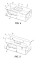
- the electronic module tag 20 can be attached directly to the toner cartridge module 30, as shown in Figure 1.
- the module 30 is enclosed within a container 32 for storage and transport, as shown in Figures 3 - 5.
- the tag 20 is embedded in the material forming the container (such as corrugated cardboard).
- the container may also enclose packing material (not shown) to protect the enclosed module.
- the container may enclose multiple modules, which may be identical to one another, or may form a set of related modules.
- the module such as the toner cartridge 30, is associated with an electronic module tag 20 on the container 32 by placing the module in the container having the programmable electronic tag 20.
- the module enclosed within the container may or may not have a separate electronic tag 20 affixed directly to the module ( Figure 1).
- the electronic tag 20 is attached with a label 33 to the container 32.
- One portion of the container (shown in Figure 4 as the top) has an opening separation 34 that is adapted to expand upon opening the container.
- the opening separation is formed in the top surface by forming the top surface as two sections 36, 38 of container material that meet at a seam that forms the opening separation 34.
- the container with the opening separation expanded to open the container is shown in Figure 5.
- Other types of opening separations are also known.
- the container may be formed of a container body with an open side and a separate piece of material to form a lid, having an opening separation that extends around the perimeter of the lid, where the edge of the lid meets the container body.
- Other types of opening separations might include a pull tab that tears the container material, or that has a line of perforations to permit the pull tab to separate to sections of the container.
- the label bearing the electronic tag is securely attached to the container, preferably spanning the opening separation.
- Tag programming or tag writing equipment One system for programming tag memories is described in U.S. Patent Application Serial No. 10/634,934, entitled Control Of Programming Electronic Devices, and filed August 5, 2003 by Alberto A. Rodriguez et al, the contents of which are hereby incorporated by reference.
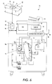
- FIG. 6 shows a representative printing apparatus 70 that might use the module 30 enclosed within the container 32.
- the representative printing apparatus includes a printing subsystem 72, which, in the illustrated example, is a xerographic printing subsystem that includes a photoreceptor 74, and a developer 73.
- a toner cartridge such as the toner cartridge module 30 enclosed within the container, is inserted into the printing subsystem.
- the developer draws toner from the toner cartridge into the developer.
- the printing apparatus additionally includes a fuser subassembly 78, an electronic subsystem 80 for processing control signals, and a distribution component 82 for controlling the distribution of electronic signals from the electronic subsystem to the printing subassembly and the fusing subassembly.
- the distribution components may also deliver information to a graphical display 84 for conveying information to the machine user.
- the printing apparatus may include a copying function, in which case a document handler 86 passes documents past a scanner 88.
- the printing apparatus includes a printer tag reader 90 that includes a wireless reader communication element 92 for receiving information transmitted by the communication element 26 of the module tag 20.
- the tag reader on the printing apparatus includes reader electronics 94 and an RF antenna forming the wireless reader communication element 92.
- the RF antenna emits radio frequency signals of sufficient strength to energize the RF antenna forming the tag communication element 26 on the tag when the tag is brought into proximity with the printer tag reader.
- the tag communication element Upon being energized, the tag communication element transmits information stored in the tag memory portion of the tag electronics 24.
- the wireless reader communication element 92 receives that information, and either processes the information within the printer tag reader electronics 94, or transmits the information to the printer electronic subsystem 80 of the printing apparatus.
- the printer tag reader electronics 94 or the printer electronic subsystem 80 analyze the tag information received from the module tag 20.
- the tag information read and analyzed by the printer tag reader electronics 94 or the printer electronic subsystem 80 includes the configuration information stored in the tag memory.
- the analysis may be to verify that the tag information indicates that the module enclosed in the container is appropriate for the particular printing apparatus by comparing the tag configuration information with predetermined configuration parameters.
- the printer electronic subsystem may verify that the tag information indicates that the module is intended for a printing apparatus with the appropriate type of maintenance agreement that covers the particular printing apparatus 70.
- the electronic subsystem may use the tag information from the tag on the container to determine the type of material in the container.
- the printer electronic subsystem 80 may be configured to perform various actions depending on the information received.
- the information received from the tag may indicate to the electronic subsystem how the printer should be configured to take advantage of the module contained in the container.
- the electronic subsystem can also be configured to issue a notice on a printer user interface, such as a graphical display 84, if the tag information read from the module tag indicates that an incorrect module is being presented to the printing apparatus.
- the electronic subsystem may even be programmed to block insertion of the module into the printing apparatus if the information read from the tag memory does not agree with the expected information.
- a module tag 20 is attached directly to the module 30 so that the contents of the module tag can be read by a printer tag reader 76 in the printing apparatus during use of the printing apparatus.
- the printing apparatus may be adapted so that if the printing apparatus, through the printer tag reader, determines that the module tag is programmed with one set of configuration information, the printing apparatus operates in a first manner, or if the module tag is programmed with a second set of configuration information, the printing apparatus operates in a second, different manner.
- the module is a toner cartridge for a developer 73, such differences may include adjustments such as altering the concentration of toner deposited by the developer onto the photoreceptor 74. Or the differences may include adjustments to the methodology the printing apparatus uses to estimate toner usage, or other factors affecting printer performance.
- the printer tag reader is installed adjacent where the module 30 is to be installed.
- the printer may include an insertion tray 75 to receive the toner module.
- the printer tag reader 76 may be contained in the insertion tray.
- a printer tag reader 90a is mounted adjacent the insertion tray, or along the path that the module 30 takes as the module is inserted into the printer.
- the printer tag reader 90a includes a wireless communication element 92a and reader electronics 94a.
- Information can also be stored in the tag memory of the module tag 20 after the module tag has been attached to a particular module, attached to the container enclosing a particular module, or in some other manner associated with a particular module. Thus, information can be added to the tag memory at different times and when the module is at different locations.
- Information stored on the module tag may relate to the printer machine with which the module is to be used, such as the printer 70.
- certain information about the usage of the printer and/or the module may be stored in the module tag. Such information may include number of prints or copies made, amount of toner used, or similar operational information.
- the information stored in the tag memory may affect operation of the machine.
- the information may affect machine settings, the number of machine operations (prints or copies) performed, and other performance issues. Therefore, malfunctions in the module tag, including errors in data stored in the tag memory, may impact machine performance.
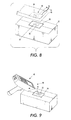
- a tag diagnostic device 40 ( Figures 8 and 9) is adapted to determine if there is a malfunction in the tag, including the tag memory.
- the tag diagnostic device 40 may have a fixed location, as shown in Figure 8.
- the tag diagnostic device is secured to a fixture 42.
- the stationary tag diagnostic device and its fixture are configured so that a module or a container enclosing a module, bearing a programmable electronic module tag, can be brought into proximity with the tag diagnostic device.
- the tag diagnostic device may be included in a portable tag processing device 50, as shown in Figure 9.
- the tag diagnostic device 40 includes a tag reader that can electronically read information from the electronic module tag, and a tag writer that can program information into the electronic module tag. In either the fixed or portable tag diagnostic device, most, if not all, components may be shared between the tag reader and the tag writer.
- the tag diagnostic device 40 includes diagnostic device electronics 44 (shown stylistically), and a diagnostic device communication element 46.
- the diagnostic device communication element 46 communicates with the tag communication element 26 of the electronic module tag to form a communication link between the tag diagnostic device and the electronic module tag.
- the tag diagnostic device communication element 46 is a wireless communication element, such as an RF antenna.
- the RF antenna of the tag diagnostic device emits sufficient energy to energize the RF antenna of the wireless communication element 26 of the tag when the tag diagnostic device communication element 46 and the tag communication element 26 are within a predetermined operating range of one another.
- the tag diagnostic device establishes a communication link between the tag diagnostic device and the electronic tag.
- the tag diagnostic device and the electronic tag can exchange information across that communication link.
- a radio frequency wireless communication link is shown, other types of communication links can also be used.
- wires connected with plugs or sockets can provide wired communication links between the tag reader and the electronic tag.
- An external communication link provided by, for example, a wire or cable 48, allows data to pass to and/or from the tag diagnostic device to another system, such as a computer or other information management system.
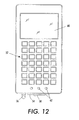
- a portable tag processing device 50 incorporating the tag diagnostic device 40 includes user interface components.
- Such user interface components include a user input element so a user can provide information to the tag diagnostic device, and a user notification element so the tag diagnostic device can convey information to the user.
- FIG. 10 - 13 An exemplary portable tag processing device is shown in Figures 10 - 13.
- An exemplary portable tag processing device is described in U.S. Patent Application Serial No. xx/xxx,xxx (Attorney Docket No. A2569-US-NP), entitled “Control of Programmable Modules,” filed concurrently herewith by Heiko Rommelman et al, the contents of which are hereby incorporated by reference.
- the user input element includes a keypad 52 connected to electronics 44 contained inside the processing service.
- the keypad provides a means for a user to supply input information, such as programming instructions, to the device electronics 44.
- Information, such as user input information can also be supplied to the tag processing device through other communication ports, such as a wired communication port 54.
- the wired communication port can be either a serial or parallel data port.
- a connecting device such as a cable, is selectively attached to the wired communications port.
- External user information input devices such as a laptop or desktop computer, can be connected to the tag processing device though the communication port 54.
- the device electronics of the tag processing device may include device memory for storing information during operation. Internal storage allows the tag processing device to download (or upload) data and information at intervals. This capability to store information allows tag processing device to be operated for a time without being in continuous communication with an external system through the communications port.
- Communication to the portable tag diagnostic device can also be conducted wirelessly, such as with infrared or radio frequency signals.
- An external antenna 56 provides an exemplary connection point for receiving user input information from another element or system over a wireless communication link.
- An antenna switch 58 provides the ability to connect or disconnect the external antenna, or to transfer communication capability between the external antenna and the communications port 54. Persons familiar with the art will identify other mechanisms for supplying information from a user to the tag processing device 50 for use by the tag diagnostic device.
- the tag diagnostic device electronics 44 include a data processor 59.
- the data processor processes data received at the diagnostic device communication element 46, and also information received from a user input element such as the keypad 52 or a device communicating through the wired communication port 54 or the other external antenna 56.
- the data processor manipulates the data according to predetermined criteria.
- the data processor can be adapted to interpret instructions received from the user input element, to verify information that is received from a module tag over the programmer communication element 46, or to perform calculations upon data received from the module tag.
- the tag diagnostic device processor is also adapted to cause certain information to be communicated to the module tag, such as by transmitting the information over the programmer communication element 46.
- the user interface of the tag processing device also includes user notification elements for communicating information to the user.
- the user notification elements may include a graphical user interface 60, signal lights 62, and/or an audio output 64.
- the graphical user interface is adapted to display graphical or text messages, and may be a liquid crystal display (LCD) screen.
- the diagnostic device electronics control the messages displayed on the graphical user interface.
- the graphical user interface can also display information confirming the data entered by the user on the keypad 52.
- Signal lights 62 can provide simple visual signals to the user. For example, two signal lights may be included, with one red to indicate a negative condition or result, and the other green to indicate a positive condition or result. A third signal light may indicate a separate function, such as a power-on condition, or may provide a tri-level condition indicator. Other embodiments may have other numbers of signal lights.
- the signal lights may be light emitting diodes (LED's), incandescent bulbs, or other light emitting devices.
- An audio output such as a speaker 64, is adapted to provide additional user notification by emitting one or more audible signals.
- audible signals may signal different conditions. For example, a 'buzzer' tone may indicate a negative condition or result, while a 'beep' tone may indicate a positive condition or result.
- Audible signals can be used to draw attention to certain conditions. In certain instances, simple signaling devices such as the signal lights and the audio signal output may be able to provide sufficient information to the user, eliminating the need for the graphical user interface.
- the communication ports permit bi-directional information generated by the tag processing device can be communicated to an external device, such as a computer.
- the portable tag processing device 50 is powered by a self-contained battery 66.
- a switch 68 allows the user to selectively turn the tag processing device on and off.
- the portable tag processing device is tethered to a power source with a power cord (not shown).
- the tag diagnostic device and other elements of the tag processing device may be positioned at the point of use at which the tag diagnostic device is proximate the module or module-enclosing container having the programmable module tag.
- the tag diagnostic device antenna 46 and some immediate support electronics may be at the point of use.
- Other portions of the processor electronics and the user interface elements can be positioned remote from the point of use, connected to the tag diagnostic device antenna by additional communication elements (not shown).
- the tag diagnostic device identifies a category into which to classify the module bearing the electronic module tag 20.
- the data processor 59 analyzes information received at the communication element 46 from the module tag to determine if the information matches one or another of predetermined category criteria.
- the data processor may contain predetermined category criteria pertaining to a first category, a second category, etc. Such categories may include categories related to the amount that the module has been used (i.e. number of prints produced by a print module), or type of marketing program applicable to the module (sold or leased), or type of service program (all-inclusive, or individual charges), or other criteria.
- the data processor generates a processor result in accordance with the category match as determined in accordance with the category criteria.
- the processor results are communicated to another system, such as the computer 95, or to the user through a user interface such as the graphical user interface 60.
- the tag processor reads tag information from tags attached to expended (used) modules.
- the tag information may include information about the amount of usage to which the module has been put.
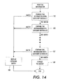
- the data processor can categorize the module into one of a plurality of usage categories, and display that categorization to the user. Referring to the exemplary categorization process shown in Figure 14, the processor compares received tag information with one category criteria C1 (183) to determine if the module fits a first category. If the tag information does not indicate a match for category criteria C1, the processor compares the tag information with a second category criteria C2 (185) to determine if the module fits a second category.
- the processor can continue the comparison process for a number of category criteria CN (187).
- the category match can be displayed 188 to the use on the graphic user interface 60, or, if there are a small number of categories, the category match can be displayed using the lights 62 or even audible signals from the speaker 64.
- the processor may include the capability to display a "no match" result 189 if the tag information does not match any of the predetermined category criteria.
- the user can use that categorization to place the module in an appropriate refurbishment or re-manufacturing category.
- the tag processor may include an on-board printer (not shown)_ for printing a label with the determined categorization, which label can then be applied to the module.
- the module bearing the tag may be a replaceable print module containing toner, a photoreceptor, and other elements for use in a xerographic printer.
- the tag information maybe the number of images the replaceable print module has made.
- the tag processing device reads that tag information, and identifies the numbers of images in that information.
- the processor compares the read number of images against one or more category criteria that include imaging thresholds. For example, if the number of images produced is less than a first threshold, the module maybe placed in a "refill" category. If the number of images is greater than the first threshold, but less than a second (higher) threshold, the module may be placed in a "light re-manufacturing" category. If the number of images is greater than the second threshold, the module may be placed in a "full re-manufacturer"' category.
- the categorization information the user can direct the module to the most appropriate processing facility.
- Categorization may include non-exclusive categorization, or categorization based on multiple criteria. For example, if the number of images is less than the first threshold AND the date of manufacture (as indicated by tag information) is prior to a predetermined date, the module may be placed in a particular category, different from the category if the date of manufacture had been subsequent to the predetermined date. After studying the subject disclosure, a person of skill in the art can construct a categorization process consistent with any desired sorting objective.
- the data processor 59 includes diagnostic and repair functionality.
- the data processor may be programmed with instructions to cause the tag diagnostic device to perform diagnostic tests on an electronic module tag.
- the data processor causes the tag diagnostic device to communicate predetermined information requests to the electronic module tag.
- the data processor analyses the response (or lack thereof) from the module tag to determine whether the electronic module tag is operating within its proper parameters.
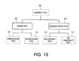
- the data processor may be adapted to perform sequences of diagnostic tests 100, such as those outlined in Figure 15.
- one branch of tests may include generic tests 102 that are applicable to electronic tags of many different categories. Such tests include communication sequence tests 104 to confirm that the electronic module tag 20 is communicating correctly through the tag communication element 26. The generic tests may also include authentication tests 106 to confirm the identity and authenticity of the electronic module tag.
- Another branch of tests may include tests that are particular to a specific model or category of electronic tag.
- category specific tests 108 may include data integrity tests 110 that confirm that the data read from the electronic tag is of the expected size and type, and tag configuration compatibility tests 112 for confirming that the data read from the electronic tag is consistent with the module or machine with which the electronic module tag is associated.
- Figure 16 illustrates conceptually some of the diagnostic tests that may be performed by the tag processor under the control of the programmed data processor 59.
- the test categories are shown in a particular order that is logical in many circumstances. However, the tests may be performed in different orders.
- the different tests determine if the tag is operating within predetermined parameters of acceptable tag performance, using different criteria. From the different criteria, the diagnostic device can identify one or more error categories for a tag malfunction, and to communicate such information to the user of the diagnostic device.
- a first set of diagnostic tests includes communication tests 104 that verify that the electronic tag is properly establishing a communication link with the tag diagnostic device. Failure to properly establish a communication link with the tag diagnostic device indicates a probable failure in the ability of the electronic tag to establish a communication link with a tag programming device or a tag reading device.
- the communication tests may include tests such as instructions to read particular cells from the tag memory 24, or instruction to write certain data to particular cells in the tag memory, and then read the data from those particular cells to confirm that the data was correctly communicated and stored.
- Certain electronic module tags have particular predetermined memory cells that cannot be written to or read from without affecting the performance of the tag. The communication tests are configured to bypass such cells and to avoid writing to or reading from such memory cells.
- the data processor determines from the communication tests 104 whether communication with the module tag is within predetermined parameters.
- the data processor causes the results of the communication tests to be communicated to the user using various user communication elements of the diagnostic device. For example, a message can be displayed on the graphical user interface 60. If the communication test indicates a failure, the data processor identifies an error category from a predetermined set of error categories, and displays 122 a corresponding error detail (such as "Device Not Responding") on the graphical user interface.
- the data processor may also activate the signal lights 62 and the audio output 64 to alert the user to the test results.
- the diagnostic device may cause a red signal light to illuminate, and/or the audio output to emit an audible signal such as a buzzer sound. If the communication tests are successful, a green signal light may be illuminated and/or the audio output may emit a different audible signal, such as a bell sound. In certain implementations, successful test results may not be communicated to the user, and the diagnostic device simply proceeds to the next tests.
- the user can initiate the communication tests by pressing a particular key or combination of keys on the keypad 52, or by communicating an instruction from an external device through one of the communication ports 54, 56, in accordance with the programming of the diagnostic device.
- authentication tests 106 can be used to verify that the electronic tag is a genuine (not counterfeit) tag.
- Authentication tests may include an emulation test to probe the electronic tag with certain types of inquiries to determine if the tag produces the appropriate, expected results.
- Tests may include memory map validation tests and memory tests to validate certain read only data in the memory element of the electronic tag. Other tests may elicit the tag identification to determine the category of electronic module tag.
- One or more communication sequence tests can be used as part of the authentication tests to verify that the electronic module tag is communicating information in the proper sequence.
- the electronic tag can be designed to produce certain predetermined results upon being presented with certain queries.
- the electronic tag may read out over the communication element the contents of certain cells in the memory element.
- the CPU of the electronic tag may perform a predetermined computation on the contents of certain cells in the memory element to produce computed results.
- the module tag then communicates these computed results over the tag communication element 26.
- the computation may encrypt the contents of one or more of the memory cells.
- the computation manipulates the contents of one or more of the memory cells in accordance with a predetermined formula.
- the predetermined formula may be fixed, or it may vary over time according to another predetermined arrangement.
- the diagnostic device 46 communication element receives the results transmitted by the tag communication element 26.
- the data processor 59 of the diagnostic device analyzes the results to determine if the results are consistent with the results expected from an authentic electronic tag 124.
- the results of the authentication tests can be communicated to the user using the graphical user interface 60, the signal lights 62, and/or the audio output 64.
- the processor can cause the graphical user interface to display a message 126 indicating that the electronic tag should be returned to the source or to another designated location.
- the tag diagnostic device proceeds with data integrity tests 110.
- the diagnostic device electronics 44 and the data processor 59 cause the diagnostic device communication element (RF antenna) 46 to emit one or more test inquiries.
- the tag communication element (RF antenna) 26 receives the test inquiries, and processes them in accordance with the design of the module tag to produce tag results.
- the tag communicates the tag results from the tag communication element.
- the data integrity tests may include a data format validation, a data range validation, and a validation of relationships among variables used in the tag electronics.
- the data processor compares the received tag results with the expected tag results 128. If the module fails the data integrity tests 110, the data processor can cause the user interface to display failure indications. For example, the graphical user interface 60 may display a message 130 that the data integrity tests failed. The message may include instructions to return the assembly of the module tag and associated module to a source, such as the manufacturer or a distributor. Other failure indications may include illumination of a particular one of the signal lights 62 and/or a particular type of audio signal from the audio output 64.
- the machine user may need to replace a module associated with a tag that fails any one of the communication tests 104, the tag authentication tests 106, or the data integrity tests 108.
- the user of the diagnostic device enters information 132 about the machine with which the module is to be used (machine configuration information) for submission to the appropriate ordering or purchasing systems.
- machine configuration information information 132 about the machine with which the module is to be used
- the diagnostic system or an external ordering system identifies the module configuration appropriate for that machine configuration 134.
- the nature of the tag failure may indicate that the tag can be reprogrammed for proper use. Such circumstances may particularly occur when the communication tests and the authentication tests are successful, but certain of the data integrity tests fail.
- the data processor upon analyzing the nature of the failure, may determine that the failure coincides with a category of failure that can be rectified by reprogramming the tag.
- a reprogramming process 133 is invoked. Using information such as the machine configuration and other information either read from the tag, or entered by the user, the data processor 59 of the diagnostic tool activates the diagnostic device communication element (RF antenna) 46 to transmit reprogramming information.
- the tag communication element (RF antenna) 26 receives the programming information and stores the correct tag data in the tag memory 24.
- the reprogramming process can be automatic, or it may interact with the user by displaying instructions or queries on the graphical user interface 60 and awaiting user input from the keypad 52 or other user input mechanism. One particular interactive process may include authentication of the user's reprogramming authority.
- the diagnostic device may display a request for the user's identity.
- the user may supply the requested information through a series of entries using the keypad 52 or through an identity card reader attached to the diagnostic device.
- the data processor can determine from the supplied identity information whether the user has authority to initiate the reprogramming of the tag. Once the tag has been reprogrammed, the reprogrammed tag can be subjected to the diagnostic tests to confirm successful reprogramming. In certain circumstances, the retesting may bypass the communication tests 104 and the authentication tests 106, and proceed directly to the data integrity tests 110.
- a set of compatibility tests 112 are invoked to verify that the electronic module tag matches the environment in which the module tag is being used.
- the modules with which the module tag is associated are designed for use in particular environments, such as particular machines and particular geographic regions for optimum performance. This information is stored on the module tag.
- the compatibility tests 112 may include a geographic validation test to confirm that the module to which the module tag is associated is being used in the geographic region for which the module was designed and manufactured.
- the compatibility tests may also include machine product family and machine product type validation tests.
- the operator of the diagnostic device enters information about the configuration of the machine in which the module is being used or to be used 136. The operator enters this information using the keypad 52, or using another device such as a portable computer that communicates with the diagnostic device through one of the communication ports 54, 56.
- the machine product family and machine product type validation tests verify compatibility between the machine and the module to which the module tag is associated.
- the machine product family and machine product type validation tests are combined into a single machine model validation test that validates the particular machine model number against a list of proper machine models for the module identified by the information read by the tag diagnostic device reading the module tag.
- the compatibility tests may also include a service plan validation test.
- Machines in which the module to which the module tag is associated may operate under different service plans that call for different types of modules. For example, if machine is a printer and the module is a replaceable module, such as a toner cartridge, different types of toner cartridges may be used for different service plans.
- One type of module may be appropriate for a machine for which the user purchases replaceable modules, while a different type of module is appropriate for a machine for which the user pays a set per print charge, and does not purchase individual replaceable modules.
- the service plan validation test verifies the correctness of the tag for the machine's service plan to ensure that the tag is of the type to record and communicate to the user the appropriate type of information that will allow the user to properly manage usage of the machine under that user's machine service plan.
- the configuration information includes information about the machine service plan.
- the data processor examines the results of the compatibility tests 112 to determine 138 if the module tag is compatible with the geographic region, the machine, and the machine service plan. Because the tag is associated with a particular replaceable module for the machine, the compatibility tests for the module tag also reveal to at least some degree whether the module is compatible with the machine.
- the diagnostic device proceeds to the end of the diagnostic routine.
- the diagnostic device may display indications to the user that all diagnostic tests were successful 142.
- the diagnostic device displays a failure indication.
- the user interface can display a text message such as, "incompatible unit" 140, and may also provide text or graphical information about the nature of the incompatibility.
- a signal may be exhibited visually by at least one of the signal lights 62, and audibly by the audio output 64. From the nature of the incompatibility, the diagnostic device or other system may identify the correct module to order, and generate the correct module order configuration 134.
- the diagnostic device reads once all the contents of the tag memory, and stores the tag data in memory on board the diagnostic device.
- the data processor is then able to perform authentication tests 106, data integrity tests 110, and tag compatibility tests 112 on the tag data without having to retransmit data from the module tag. Reading all the data at once also eliminates communication of selective data, which communication could, if intercepted, reveal proprietary information concerning the data structure of information stored in the tag memory.
- Figure 17 illustrates an exemplary organization of the software contained in the diagnostic device.
- the software is organized modularly.
- the modular organization of the diagnostic software provides ease of support and maintenance. New tests specific to particular module tags can be added to the diagnostic software without disrupting other portions of the software.
- the main graphical user interface (GUI) module 150 contains code that controls the user's access to the capabilities of the diagnostic device.
- the main graphical user interface module may control a password control interface on the graphical user interface 60. This module may also control the user's navigation through the different tests.
- the mode flow/control module 152 controls the interaction of other modules, including the diagnostic tests module 154 and the tag dump control module 156.
- the tag dump control module governs the reading of the entire contents of the module tag memory so that the diagnostic device can analyze the data.
- a separate tag dump mode graphical user interface module 158 may provide information to the user vice the graphical user interface 60.
- a diagnostic mode graphical user interface (GUI) module 160 controls instructions and information provided to the user during the diagnostic tests. The diagnostic mode GUI module causes the different error messages to display in different colors on the graphical user interface for added user attention.
- An application access security module allows access to and use of the diagnostic tests of the diagnostic device to be limited. The application access security module performs password validation and provides a mechanism for changing passwords.
- a communication module 164 handles low level (basic) communications between the diagnostic device and the module tag.
- An error message module 166 contains a list of all the error categories and their associated error codes and messages to be displayed on the graphical user interface 60.
- a hardware (H/W) peripherals module 168 contains code for handling interaction with peripheral hardware such as an accessory bar code scanner (not shown).
- One or more feature description specific modules 170 contain information relating to individual specific models of tags, specific tag features, and particular variables, definitions, interpretation of data, etc.
- a PC/Network communications module 172 contains the code necessary to communicate information via one of the diagnostic device communication ports 54, 56 to a data network computer, or other external device.
- An encrypted data file generation module 174 contains code to encrypt the data retrieved from the tag by the tag dump control module. Encrypting the tag data protects the information from unauthorized access.
- These software modules may be stored in a memory device such as a hard drive (not shown) inside the diagnostic device.
- the software modules may also be embedded in firmware formed as part of the diagnostic device electronics 44 ( Figure 11).
- FIGS 8 and 9 conceptually illustrate operation of the electronic module tag diagnostic system and method.
- the drawing shows an arrangement in which the electronic module tag 20 is secured to a container 32 enclosing the module
- the process can also be applied to an electronic module tag attached to the module itself.
- the process can be applied to a module having an attached module tag whether the module is enclosed within a container or outside of a container.
- the process can be applied to a module installed in a machine.
- the electronic module tag 20 is brought into proximity with the tag diagnostic device by bringing the module with which the electronic module tag 20 is associated into proximity with the tag diagnostic device.
- the container 32 enclosing the module 30 ( Figure 3) and bearing the electronic module tag 20 is brought close enough to the stationary tag diagnostic device that the communication link is established between the electronic module tag and the tag diagnostic device.
- the communication link is established through the tag diagnostic device communication element 46 and the module tag communication element 26.
- the tag diagnostic device 50 of Figure 9 the tag diagnostic device can be brought into proximity with the electronic module tag.
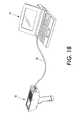
- Figure 18 illustrates an embodiment in which an external device, such as a notebook computer 95 is attached to the diagnostic device 50 by a cable 96.
- One end of the cable is attached to the diagnostic device through the wired communications port 54.
- the other end of the cable attaches to the notebook computer through one of the several ports available on a typical computer, such as parallel (printer) port, a serial port, or a USB (universal serial bus) port.
- the computer 95 can be used to provide instructions to the diagnostic device.
- the computer can download from the diagnostic device the results of the tests performed on module tags.
- the computer may be continuously connected to the diagnostic device, or it may be connected only occasionally.
Abstract
Description
In a further embodiment:
In addition to, or in lieu of, the
Claims (10)
- An electronic diagnostic device for testing electronic monitoring tags associated with replaceable modules for a printing apparatus, the diagnostic device comprising:a tag reader comprising a reader wireless communication element;
wherein the tag reader is adapted to read tag diagnostic information from a first electronic monitoring tag associated with a replaceable module for a printing apparatus using the reader wireless communication element;a data processor in communication with the tag reader;
wherein the data processor is adapted to determine from the tag diagnostic data whether the first electronic monitoring tag is operating within predetermined parameters;
wherein the data processor contains a predetermined set of error categories;
wherein the data processor is additionally adapted to identify one of the error categories if the first electronic monitoring tag is operating outside the predetermined parameters, and to generate error category information; anda results communication element in communication with the data processor adapted to communicate the error category information generated by the data processor. - The electronic diagnostic device of claim 1, wherein the results communication element is a results display for displaying the error category information to a user.
- The electronic diagnostic device of claim 2, wherein the results display is a graphical user interface.
- The electronic diagnostic device of claim 1, wherein:the results communication element is adapted to display one of a predetermined set of error messages; andeach of the error messages corresponds to one of the error categories.
- The electronic diagnostic device of claim 1, wherein:the data processor is additionally adapted to prepare corrective tag information responsive to the error category information; andthe results communication element is a tag writer adapted to program the first electronic monitoring tag with the corrective tag information generated by the data processor in response to the error category information.
- An electronic diagnostic device comprising:a tag reader;
wherein the tag reader is adapted to read tag diagnostic information from a first electronic monitoring tag associated with a replaceable module of a printing apparatus;a data processor in communication with the tag reader;
wherein the data processor is adapted to analyze the tag diagnostic data to produce tag diagnosis information;a results communication element in communication with the data processor for communicating the tag diagnosis information. - A method of testing electronic monitoring tags associated with replaceable modules of printing apparatus, the method comprising:bringing a portable electronic reader device into proximity with a first electronic tag associated with a replaceable module of a printing apparatus;causing the portable electronic tag reader to read tag diagnostic data from the first electronic tag;electronically determining from the tag diagnostic data whether the first electronic tag is operating within predetermined operating parameters;transmitting an error signal if the first electronic tag is not operating within the predetermined operating parameters.
- The method of claim 7, wherein causing the portable electronic tag reader to read the tag diagnostic data from the first electronic tag comprises causing the tag reader to read all of the data stored in the first electronic tag.
- The method of claim 7, wherein causing the portable electronic tag reader to read the tag diagnostic data from the first electronic tag comprises causing the tag reader to receive the tag diagnostic data over a wireless communication link between the first electronic tag and the tag reader.
- The method of claim 9, wherein causing the tag reader to receive the tag diagnostic data over a wireless communication link comprises causing the tag reader to receive the tag diagnostic data over a radio frequency communication link between the first electronic tag and the tag reader.
Applications Claiming Priority (2)
| Application Number | Priority Date | Filing Date | Title |
|---|---|---|---|
| US850190 | 1992-03-11 | ||
| US10/850,190 US7158032B2 (en) | 2004-05-20 | 2004-05-20 | Diagnosis of programmable modules |
Publications (2)
| Publication Number | Publication Date |
|---|---|
| EP1598767A2 true EP1598767A2 (en) | 2005-11-23 |
| EP1598767A3 EP1598767A3 (en) | 2012-05-02 |
Family
ID=34939892
Family Applications (1)
| Application Number | Title | Priority Date | Filing Date |
|---|---|---|---|
| EP05104243A Withdrawn EP1598767A3 (en) | 2004-05-20 | 2005-05-19 | Diagnosis of programmable modules |
Country Status (6)
| Country | Link |
|---|---|
| US (1) | US7158032B2 (en) |
| EP (1) | EP1598767A3 (en) |
| JP (1) | JP4819396B2 (en) |
| CN (1) | CN100472552C (en) |
| BR (1) | BRPI0501775A (en) |
| CA (1) | CA2507385C (en) |
Cited By (3)
| Publication number | Priority date | Publication date | Assignee | Title |
|---|---|---|---|---|
| EP1870778A3 (en) * | 2005-09-27 | 2008-07-09 | Samsung Electronics Co., Ltd. | Diagnosing an image forming apparatus |
| EP2490075A1 (en) * | 2011-02-18 | 2012-08-22 | Konica Minolta Business Technologies, Inc. | Image formation device |
| EP3039615B1 (en) * | 2013-08-28 | 2019-07-10 | Hewlett-Packard Development Company, L.P. | Cartridge comprising an auto-destruct feature |
Families Citing this family (274)
| Publication number | Priority date | Publication date | Assignee | Title |
|---|---|---|---|---|
| US9060770B2 (en) | 2003-05-20 | 2015-06-23 | Ethicon Endo-Surgery, Inc. | Robotically-driven surgical instrument with E-beam driver |
| US20070084897A1 (en) | 2003-05-20 | 2007-04-19 | Shelton Frederick E Iv | Articulating surgical stapling instrument incorporating a two-piece e-beam firing mechanism |
| US7053776B2 (en) * | 2004-05-20 | 2006-05-30 | Xerox Corporation | Control of programmable modules |
| US11890012B2 (en) | 2004-07-28 | 2024-02-06 | Cilag Gmbh International | Staple cartridge comprising cartridge body and attached support |
| JP4575067B2 (en) * | 2004-07-29 | 2010-11-04 | ルネサスエレクトロニクス株式会社 | IC tag semiconductor device, IC tag and IC tag control method |
| JP2006268578A (en) * | 2005-03-24 | 2006-10-05 | Fuji Xerox Co Ltd | Information providing system and image formation device |
| US7934630B2 (en) | 2005-08-31 | 2011-05-03 | Ethicon Endo-Surgery, Inc. | Staple cartridges for forming staples having differing formed staple heights |
| US7669746B2 (en) | 2005-08-31 | 2010-03-02 | Ethicon Endo-Surgery, Inc. | Staple cartridges for forming staples having differing formed staple heights |
| US11484312B2 (en) | 2005-08-31 | 2022-11-01 | Cilag Gmbh International | Staple cartridge comprising a staple driver arrangement |
| US10159482B2 (en) | 2005-08-31 | 2018-12-25 | Ethicon Llc | Fastener cartridge assembly comprising a fixed anvil and different staple heights |
| US11246590B2 (en) | 2005-08-31 | 2022-02-15 | Cilag Gmbh International | Staple cartridge including staple drivers having different unfired heights |
| US20070106317A1 (en) | 2005-11-09 | 2007-05-10 | Shelton Frederick E Iv | Hydraulically and electrically actuated articulation joints for surgical instruments |
| US7916008B2 (en) * | 2005-12-15 | 2011-03-29 | Lear Corporation | RFID systems for vehicular applications |
| US8708213B2 (en) | 2006-01-31 | 2014-04-29 | Ethicon Endo-Surgery, Inc. | Surgical instrument having a feedback system |
| US20120292367A1 (en) | 2006-01-31 | 2012-11-22 | Ethicon Endo-Surgery, Inc. | Robotically-controlled end effector |
| US8186555B2 (en) | 2006-01-31 | 2012-05-29 | Ethicon Endo-Surgery, Inc. | Motor-driven surgical cutting and fastening instrument with mechanical closure system |
| US11224427B2 (en) | 2006-01-31 | 2022-01-18 | Cilag Gmbh International | Surgical stapling system including a console and retraction assembly |
| US8820603B2 (en) | 2006-01-31 | 2014-09-02 | Ethicon Endo-Surgery, Inc. | Accessing data stored in a memory of a surgical instrument |
| US7845537B2 (en) | 2006-01-31 | 2010-12-07 | Ethicon Endo-Surgery, Inc. | Surgical instrument having recording capabilities |
| US7753904B2 (en) | 2006-01-31 | 2010-07-13 | Ethicon Endo-Surgery, Inc. | Endoscopic surgical instrument with a handle that can articulate with respect to the shaft |
| US11278279B2 (en) | 2006-01-31 | 2022-03-22 | Cilag Gmbh International | Surgical instrument assembly |
| US11793518B2 (en) | 2006-01-31 | 2023-10-24 | Cilag Gmbh International | Powered surgical instruments with firing system lockout arrangements |
| US20110290856A1 (en) | 2006-01-31 | 2011-12-01 | Ethicon Endo-Surgery, Inc. | Robotically-controlled surgical instrument with force-feedback capabilities |
| US8992422B2 (en) | 2006-03-23 | 2015-03-31 | Ethicon Endo-Surgery, Inc. | Robotically-controlled endoscopic accessory channel |
| US8322455B2 (en) | 2006-06-27 | 2012-12-04 | Ethicon Endo-Surgery, Inc. | Manually driven surgical cutting and fastening instrument |
| JP4921085B2 (en) * | 2006-09-08 | 2012-04-18 | キヤノン株式会社 | Image forming apparatus and image forming system |
| US10568652B2 (en) | 2006-09-29 | 2020-02-25 | Ethicon Llc | Surgical staples having attached drivers of different heights and stapling instruments for deploying the same |
| US20080138096A1 (en) * | 2006-12-07 | 2008-06-12 | Xerox Corporation | Detached apparatus identifying method and an image forming device including the same |
| US20080138098A1 (en) * | 2006-12-07 | 2008-06-12 | Xerox Corporation | Detached apparatus identifying method and an image forming device including the same |
| US20080138095A1 (en) * | 2006-12-07 | 2008-06-12 | Xerox Corporation | Detached apparatus identifying method and an image forming device including the same |
| US20080138097A1 (en) * | 2006-12-07 | 2008-06-12 | Xerox Corporation | Detached apparatus identifying method and an image forming device including the same |
| US11291441B2 (en) | 2007-01-10 | 2022-04-05 | Cilag Gmbh International | Surgical instrument with wireless communication between control unit and remote sensor |
| US8652120B2 (en) | 2007-01-10 | 2014-02-18 | Ethicon Endo-Surgery, Inc. | Surgical instrument with wireless communication between control unit and sensor transponders |
| US8684253B2 (en) | 2007-01-10 | 2014-04-01 | Ethicon Endo-Surgery, Inc. | Surgical instrument with wireless communication between a control unit of a robotic system and remote sensor |
| US8540128B2 (en) | 2007-01-11 | 2013-09-24 | Ethicon Endo-Surgery, Inc. | Surgical stapling device with a curved end effector |
| US8727197B2 (en) | 2007-03-15 | 2014-05-20 | Ethicon Endo-Surgery, Inc. | Staple cartridge cavity configuration with cooperative surgical staple |
| US8931682B2 (en) | 2007-06-04 | 2015-01-13 | Ethicon Endo-Surgery, Inc. | Robotically-controlled shaft based rotary drive systems for surgical instruments |
| US11857181B2 (en) | 2007-06-04 | 2024-01-02 | Cilag Gmbh International | Robotically-controlled shaft based rotary drive systems for surgical instruments |
| US11849941B2 (en) | 2007-06-29 | 2023-12-26 | Cilag Gmbh International | Staple cartridge having staple cavities extending at a transverse angle relative to a longitudinal cartridge axis |
| BRPI0901282A2 (en) | 2008-02-14 | 2009-11-17 | Ethicon Endo Surgery Inc | surgical cutting and fixation instrument with rf electrodes |
| US8636736B2 (en) | 2008-02-14 | 2014-01-28 | Ethicon Endo-Surgery, Inc. | Motorized surgical cutting and fastening instrument |
| US9179912B2 (en) | 2008-02-14 | 2015-11-10 | Ethicon Endo-Surgery, Inc. | Robotically-controlled motorized surgical cutting and fastening instrument |
| US7866527B2 (en) | 2008-02-14 | 2011-01-11 | Ethicon Endo-Surgery, Inc. | Surgical stapling apparatus with interlockable firing system |
| US7819298B2 (en) | 2008-02-14 | 2010-10-26 | Ethicon Endo-Surgery, Inc. | Surgical stapling apparatus with control features operable with one hand |
| US9005230B2 (en) | 2008-09-23 | 2015-04-14 | Ethicon Endo-Surgery, Inc. | Motorized surgical instrument |
| US8210411B2 (en) | 2008-09-23 | 2012-07-03 | Ethicon Endo-Surgery, Inc. | Motor-driven surgical cutting instrument |
| US11648005B2 (en) | 2008-09-23 | 2023-05-16 | Cilag Gmbh International | Robotically-controlled motorized surgical instrument with an end effector |
| US9386983B2 (en) | 2008-09-23 | 2016-07-12 | Ethicon Endo-Surgery, Llc | Robotically-controlled motorized surgical instrument |
| US8608045B2 (en) | 2008-10-10 | 2013-12-17 | Ethicon Endo-Sugery, Inc. | Powered surgical cutting and stapling apparatus with manually retractable firing system |
| US8271639B2 (en) * | 2010-02-02 | 2012-09-18 | International Business Machines Corporation | Discovering physical server location by correlating external and internal server information |
| US8783543B2 (en) | 2010-07-30 | 2014-07-22 | Ethicon Endo-Surgery, Inc. | Tissue acquisition arrangements and methods for surgical stapling devices |
| US9386988B2 (en) | 2010-09-30 | 2016-07-12 | Ethicon End-Surgery, LLC | Retainer assembly including a tissue thickness compensator |
| US9211120B2 (en) | 2011-04-29 | 2015-12-15 | Ethicon Endo-Surgery, Inc. | Tissue thickness compensator comprising a plurality of medicaments |
| US11812965B2 (en) | 2010-09-30 | 2023-11-14 | Cilag Gmbh International | Layer of material for a surgical end effector |
| US9629814B2 (en) | 2010-09-30 | 2017-04-25 | Ethicon Endo-Surgery, Llc | Tissue thickness compensator configured to redistribute compressive forces |
| US11298125B2 (en) | 2010-09-30 | 2022-04-12 | Cilag Gmbh International | Tissue stapler having a thickness compensator |
| US9016542B2 (en) | 2010-09-30 | 2015-04-28 | Ethicon Endo-Surgery, Inc. | Staple cartridge comprising compressible distortion resistant components |
| US9282962B2 (en) | 2010-09-30 | 2016-03-15 | Ethicon Endo-Surgery, Llc | Adhesive film laminate |
| US11849952B2 (en) | 2010-09-30 | 2023-12-26 | Cilag Gmbh International | Staple cartridge comprising staples positioned within a compressible portion thereof |
| US10945731B2 (en) | 2010-09-30 | 2021-03-16 | Ethicon Llc | Tissue thickness compensator comprising controlled release and expansion |
| US8695866B2 (en) | 2010-10-01 | 2014-04-15 | Ethicon Endo-Surgery, Inc. | Surgical instrument having a power control circuit |
| CA2834649C (en) | 2011-04-29 | 2021-02-16 | Ethicon Endo-Surgery, Inc. | Staple cartridge comprising staples positioned within a compressible portion thereof |
| US11207064B2 (en) | 2011-05-27 | 2021-12-28 | Cilag Gmbh International | Automated end effector component reloading system for use with a robotic system |
| US9072535B2 (en) | 2011-05-27 | 2015-07-07 | Ethicon Endo-Surgery, Inc. | Surgical stapling instruments with rotatable staple deployment arrangements |
| BR112014024098B1 (en) | 2012-03-28 | 2021-05-25 | Ethicon Endo-Surgery, Inc. | staple cartridge |
| BR112014024102B1 (en) | 2012-03-28 | 2022-03-03 | Ethicon Endo-Surgery, Inc | CLAMP CARTRIDGE ASSEMBLY FOR A SURGICAL INSTRUMENT AND END ACTUATOR ASSEMBLY FOR A SURGICAL INSTRUMENT |
| US9101358B2 (en) | 2012-06-15 | 2015-08-11 | Ethicon Endo-Surgery, Inc. | Articulatable surgical instrument comprising a firing drive |
| US9289256B2 (en) | 2012-06-28 | 2016-03-22 | Ethicon Endo-Surgery, Llc | Surgical end effectors having angled tissue-contacting surfaces |
| US9226751B2 (en) | 2012-06-28 | 2016-01-05 | Ethicon Endo-Surgery, Inc. | Surgical instrument system including replaceable end effectors |
| US9282974B2 (en) | 2012-06-28 | 2016-03-15 | Ethicon Endo-Surgery, Llc | Empty clip cartridge lockout |
| US20140001231A1 (en) | 2012-06-28 | 2014-01-02 | Ethicon Endo-Surgery, Inc. | Firing system lockout arrangements for surgical instruments |
| US11278284B2 (en) | 2012-06-28 | 2022-03-22 | Cilag Gmbh International | Rotary drive arrangements for surgical instruments |
| BR112014032776B1 (en) | 2012-06-28 | 2021-09-08 | Ethicon Endo-Surgery, Inc | SURGICAL INSTRUMENT SYSTEM AND SURGICAL KIT FOR USE WITH A SURGICAL INSTRUMENT SYSTEM |
| US9171246B2 (en) * | 2012-06-29 | 2015-10-27 | Aesynt Incorporated | System, methods, apparatuses, and computer program products for detecting that an object has been accessed |
| JP6345707B2 (en) | 2013-03-01 | 2018-06-20 | エシコン・エンド−サージェリィ・インコーポレイテッドEthicon Endo−Surgery,Inc. | Surgical instrument with soft stop |
| JP6382235B2 (en) | 2013-03-01 | 2018-08-29 | エシコン・エンド−サージェリィ・インコーポレイテッドEthicon Endo−Surgery,Inc. | Articulatable surgical instrument with a conductive path for signal communication |
| US9629629B2 (en) | 2013-03-14 | 2017-04-25 | Ethicon Endo-Surgey, LLC | Control systems for surgical instruments |
| BR112015026109B1 (en) | 2013-04-16 | 2022-02-22 | Ethicon Endo-Surgery, Inc | surgical instrument |
| US9844368B2 (en) | 2013-04-16 | 2017-12-19 | Ethicon Llc | Surgical system comprising first and second drive systems |
| US20150053746A1 (en) | 2013-08-23 | 2015-02-26 | Ethicon Endo-Surgery, Inc. | Torque optimization for surgical instruments |
| JP6416260B2 (en) | 2013-08-23 | 2018-10-31 | エシコン エルエルシー | Firing member retractor for a powered surgical instrument |
| US9317009B2 (en) * | 2014-02-19 | 2016-04-19 | Xerox Corporation | Systems and methods for mounting an externally readable monitoring module on a rotating customer replaceable component in an operating device |
| BR112016021943B1 (en) | 2014-03-26 | 2022-06-14 | Ethicon Endo-Surgery, Llc | SURGICAL INSTRUMENT FOR USE BY AN OPERATOR IN A SURGICAL PROCEDURE |
| US9733663B2 (en) | 2014-03-26 | 2017-08-15 | Ethicon Llc | Power management through segmented circuit and variable voltage protection |
| US20150297223A1 (en) | 2014-04-16 | 2015-10-22 | Ethicon Endo-Surgery, Inc. | Fastener cartridges including extensions having different configurations |
| JP6636452B2 (en) | 2014-04-16 | 2020-01-29 | エシコン エルエルシーEthicon LLC | Fastener cartridge including extension having different configurations |
| BR112016023825B1 (en) | 2014-04-16 | 2022-08-02 | Ethicon Endo-Surgery, Llc | STAPLE CARTRIDGE FOR USE WITH A SURGICAL STAPLER AND STAPLE CARTRIDGE FOR USE WITH A SURGICAL INSTRUMENT |
| JP6532889B2 (en) | 2014-04-16 | 2019-06-19 | エシコン エルエルシーEthicon LLC | Fastener cartridge assembly and staple holder cover arrangement |
| US11311294B2 (en) | 2014-09-05 | 2022-04-26 | Cilag Gmbh International | Powered medical device including measurement of closure state of jaws |
| US10111679B2 (en) | 2014-09-05 | 2018-10-30 | Ethicon Llc | Circuitry and sensors for powered medical device |
| BR112017004361B1 (en) | 2014-09-05 | 2023-04-11 | Ethicon Llc | ELECTRONIC SYSTEM FOR A SURGICAL INSTRUMENT |
| US11523821B2 (en) | 2014-09-26 | 2022-12-13 | Cilag Gmbh International | Method for creating a flexible staple line |
| US9924944B2 (en) | 2014-10-16 | 2018-03-27 | Ethicon Llc | Staple cartridge comprising an adjunct material |
| US10517594B2 (en) | 2014-10-29 | 2019-12-31 | Ethicon Llc | Cartridge assemblies for surgical staplers |
| US11141153B2 (en) | 2014-10-29 | 2021-10-12 | Cilag Gmbh International | Staple cartridges comprising driver arrangements |
| US9844376B2 (en) | 2014-11-06 | 2017-12-19 | Ethicon Llc | Staple cartridge comprising a releasable adjunct material |
| US10736636B2 (en) | 2014-12-10 | 2020-08-11 | Ethicon Llc | Articulatable surgical instrument system |
| US10004501B2 (en) | 2014-12-18 | 2018-06-26 | Ethicon Llc | Surgical instruments with improved closure arrangements |
| US9844374B2 (en) | 2014-12-18 | 2017-12-19 | Ethicon Llc | Surgical instrument systems comprising an articulatable end effector and means for adjusting the firing stroke of a firing member |
| US10085748B2 (en) | 2014-12-18 | 2018-10-02 | Ethicon Llc | Locking arrangements for detachable shaft assemblies with articulatable surgical end effectors |
| US9844375B2 (en) | 2014-12-18 | 2017-12-19 | Ethicon Llc | Drive arrangements for articulatable surgical instruments |
| US9987000B2 (en) | 2014-12-18 | 2018-06-05 | Ethicon Llc | Surgical instrument assembly comprising a flexible articulation system |
| MX2017008108A (en) | 2014-12-18 | 2018-03-06 | Ethicon Llc | Surgical instrument with an anvil that is selectively movable about a discrete non-movable axis relative to a staple cartridge. |
| US9396369B1 (en) * | 2015-02-03 | 2016-07-19 | Apple Inc. | Electronic tag transmissions corresponding to physical disturbance of tag |
| US11154301B2 (en) | 2015-02-27 | 2021-10-26 | Cilag Gmbh International | Modular stapling assembly |
| US10548504B2 (en) | 2015-03-06 | 2020-02-04 | Ethicon Llc | Overlaid multi sensor radio frequency (RF) electrode system to measure tissue compression |
| US10441279B2 (en) | 2015-03-06 | 2019-10-15 | Ethicon Llc | Multiple level thresholds to modify operation of powered surgical instruments |
| JP2020121162A (en) | 2015-03-06 | 2020-08-13 | エシコン エルエルシーEthicon LLC | Time dependent evaluation of sensor data to determine stability element, creep element and viscoelastic element of measurement |
| US9993248B2 (en) | 2015-03-06 | 2018-06-12 | Ethicon Endo-Surgery, Llc | Smart sensors with local signal processing |
| US10213201B2 (en) | 2015-03-31 | 2019-02-26 | Ethicon Llc | Stapling end effector configured to compensate for an uneven gap between a first jaw and a second jaw |
| US10238386B2 (en) | 2015-09-23 | 2019-03-26 | Ethicon Llc | Surgical stapler having motor control based on an electrical parameter related to a motor current |
| US10105139B2 (en) | 2015-09-23 | 2018-10-23 | Ethicon Llc | Surgical stapler having downstream current-based motor control |
| US10285699B2 (en) | 2015-09-30 | 2019-05-14 | Ethicon Llc | Compressible adjunct |
| US11890015B2 (en) | 2015-09-30 | 2024-02-06 | Cilag Gmbh International | Compressible adjunct with crossing spacer fibers |
| US10292704B2 (en) | 2015-12-30 | 2019-05-21 | Ethicon Llc | Mechanisms for compensating for battery pack failure in powered surgical instruments |
| BR112018016098B1 (en) | 2016-02-09 | 2023-02-23 | Ethicon Llc | SURGICAL INSTRUMENT |
| US11213293B2 (en) | 2016-02-09 | 2022-01-04 | Cilag Gmbh International | Articulatable surgical instruments with single articulation link arrangements |
| US11224426B2 (en) | 2016-02-12 | 2022-01-18 | Cilag Gmbh International | Mechanisms for compensating for drivetrain failure in powered surgical instruments |
| US10448948B2 (en) | 2016-02-12 | 2019-10-22 | Ethicon Llc | Mechanisms for compensating for drivetrain failure in powered surgical instruments |
| US10828028B2 (en) | 2016-04-15 | 2020-11-10 | Ethicon Llc | Surgical instrument with multiple program responses during a firing motion |
| US10492783B2 (en) | 2016-04-15 | 2019-12-03 | Ethicon, Llc | Surgical instrument with improved stop/start control during a firing motion |
| US10426467B2 (en) | 2016-04-15 | 2019-10-01 | Ethicon Llc | Surgical instrument with detection sensors |
| US10357247B2 (en) | 2016-04-15 | 2019-07-23 | Ethicon Llc | Surgical instrument with multiple program responses during a firing motion |
| US11607239B2 (en) | 2016-04-15 | 2023-03-21 | Cilag Gmbh International | Systems and methods for controlling a surgical stapling and cutting instrument |
| US10368867B2 (en) | 2016-04-18 | 2019-08-06 | Ethicon Llc | Surgical instrument comprising a lockout |
| US11317917B2 (en) | 2016-04-18 | 2022-05-03 | Cilag Gmbh International | Surgical stapling system comprising a lockable firing assembly |
| US20170296173A1 (en) | 2016-04-18 | 2017-10-19 | Ethicon Endo-Surgery, Llc | Method for operating a surgical instrument |
| JP2017211531A (en) * | 2016-05-26 | 2017-11-30 | 京セラドキュメントソリューションズ株式会社 | Image formation apparatus |
| US10568624B2 (en) | 2016-12-21 | 2020-02-25 | Ethicon Llc | Surgical instruments with jaws that are pivotable about a fixed axis and include separate and distinct closure and firing systems |
| JP7010956B2 (en) | 2016-12-21 | 2022-01-26 | エシコン エルエルシー | How to staple tissue |
| US20180168625A1 (en) | 2016-12-21 | 2018-06-21 | Ethicon Endo-Surgery, Llc | Surgical stapling instruments with smart staple cartridges |
| US10959727B2 (en) | 2016-12-21 | 2021-03-30 | Ethicon Llc | Articulatable surgical end effector with asymmetric shaft arrangement |
| MX2019007311A (en) | 2016-12-21 | 2019-11-18 | Ethicon Llc | Surgical stapling systems. |
| US10973516B2 (en) | 2016-12-21 | 2021-04-13 | Ethicon Llc | Surgical end effectors and adaptable firing members therefor |
| US10918385B2 (en) | 2016-12-21 | 2021-02-16 | Ethicon Llc | Surgical system comprising a firing member rotatable into an articulation state to articulate an end effector of the surgical system |
| CN110099619B (en) | 2016-12-21 | 2022-07-15 | 爱惜康有限责任公司 | Lockout device for surgical end effector and replaceable tool assembly |
| US10588631B2 (en) | 2016-12-21 | 2020-03-17 | Ethicon Llc | Surgical instruments with positive jaw opening features |
| US11419606B2 (en) | 2016-12-21 | 2022-08-23 | Cilag Gmbh International | Shaft assembly comprising a clutch configured to adapt the output of a rotary firing member to two different systems |
| US11090048B2 (en) | 2016-12-21 | 2021-08-17 | Cilag Gmbh International | Method for resetting a fuse of a surgical instrument shaft |
| US20180168615A1 (en) | 2016-12-21 | 2018-06-21 | Ethicon Endo-Surgery, Llc | Method of deforming staples from two different types of staple cartridges with the same surgical stapling instrument |
| US11517325B2 (en) | 2017-06-20 | 2022-12-06 | Cilag Gmbh International | Closed loop feedback control of motor velocity of a surgical stapling and cutting instrument based on measured displacement distance traveled over a specified time interval |
| US10307170B2 (en) | 2017-06-20 | 2019-06-04 | Ethicon Llc | Method for closed loop control of motor velocity of a surgical stapling and cutting instrument |
| US11382638B2 (en) | 2017-06-20 | 2022-07-12 | Cilag Gmbh International | Closed loop feedback control of motor velocity of a surgical stapling and cutting instrument based on measured time over a specified displacement distance |
| US10779820B2 (en) | 2017-06-20 | 2020-09-22 | Ethicon Llc | Systems and methods for controlling motor speed according to user input for a surgical instrument |
| US11653914B2 (en) | 2017-06-20 | 2023-05-23 | Cilag Gmbh International | Systems and methods for controlling motor velocity of a surgical stapling and cutting instrument according to articulation angle of end effector |
| US10881399B2 (en) | 2017-06-20 | 2021-01-05 | Ethicon Llc | Techniques for adaptive control of motor velocity of a surgical stapling and cutting instrument |
| US11324503B2 (en) | 2017-06-27 | 2022-05-10 | Cilag Gmbh International | Surgical firing member arrangements |
| US11266405B2 (en) | 2017-06-27 | 2022-03-08 | Cilag Gmbh International | Surgical anvil manufacturing methods |
| US10993716B2 (en) | 2017-06-27 | 2021-05-04 | Ethicon Llc | Surgical anvil arrangements |
| EP3420947B1 (en) | 2017-06-28 | 2022-05-25 | Cilag GmbH International | Surgical instrument comprising selectively actuatable rotatable couplers |
| US11478242B2 (en) | 2017-06-28 | 2022-10-25 | Cilag Gmbh International | Jaw retainer arrangement for retaining a pivotable surgical instrument jaw in pivotable retaining engagement with a second surgical instrument jaw |
| USD906355S1 (en) | 2017-06-28 | 2020-12-29 | Ethicon Llc | Display screen or portion thereof with a graphical user interface for a surgical instrument |
| US10765427B2 (en) | 2017-06-28 | 2020-09-08 | Ethicon Llc | Method for articulating a surgical instrument |
| US11484310B2 (en) | 2017-06-28 | 2022-11-01 | Cilag Gmbh International | Surgical instrument comprising a shaft including a closure tube profile |
| US11564686B2 (en) | 2017-06-28 | 2023-01-31 | Cilag Gmbh International | Surgical shaft assemblies with flexible interfaces |
| US10932772B2 (en) | 2017-06-29 | 2021-03-02 | Ethicon Llc | Methods for closed loop velocity control for robotic surgical instrument |
| US11304695B2 (en) | 2017-08-03 | 2022-04-19 | Cilag Gmbh International | Surgical system shaft interconnection |
| US11944300B2 (en) | 2017-08-03 | 2024-04-02 | Cilag Gmbh International | Method for operating a surgical system bailout |
| US11471155B2 (en) | 2017-08-03 | 2022-10-18 | Cilag Gmbh International | Surgical system bailout |
| US10842490B2 (en) | 2017-10-31 | 2020-11-24 | Ethicon Llc | Cartridge body design with force reduction based on firing completion |
| US10779826B2 (en) | 2017-12-15 | 2020-09-22 | Ethicon Llc | Methods of operating surgical end effectors |
| US10835330B2 (en) | 2017-12-19 | 2020-11-17 | Ethicon Llc | Method for determining the position of a rotatable jaw of a surgical instrument attachment assembly |
| US11179152B2 (en) | 2017-12-21 | 2021-11-23 | Cilag Gmbh International | Surgical instrument comprising a tissue grasping system |
| US11311290B2 (en) | 2017-12-21 | 2022-04-26 | Cilag Gmbh International | Surgical instrument comprising an end effector dampener |
| US11324501B2 (en) | 2018-08-20 | 2022-05-10 | Cilag Gmbh International | Surgical stapling devices with improved closure members |
| US11696761B2 (en) | 2019-03-25 | 2023-07-11 | Cilag Gmbh International | Firing drive arrangements for surgical systems |
| US11471157B2 (en) | 2019-04-30 | 2022-10-18 | Cilag Gmbh International | Articulation control mapping for a surgical instrument |
| US11432816B2 (en) | 2019-04-30 | 2022-09-06 | Cilag Gmbh International | Articulation pin for a surgical instrument |
| US11253254B2 (en) | 2019-04-30 | 2022-02-22 | Cilag Gmbh International | Shaft rotation actuator on a surgical instrument |
| US11426251B2 (en) | 2019-04-30 | 2022-08-30 | Cilag Gmbh International | Articulation directional lights on a surgical instrument |
| US11903581B2 (en) | 2019-04-30 | 2024-02-20 | Cilag Gmbh International | Methods for stapling tissue using a surgical instrument |
| US11452528B2 (en) | 2019-04-30 | 2022-09-27 | Cilag Gmbh International | Articulation actuators for a surgical instrument |
| US11648009B2 (en) | 2019-04-30 | 2023-05-16 | Cilag Gmbh International | Rotatable jaw tip for a surgical instrument |
| US11660163B2 (en) | 2019-06-28 | 2023-05-30 | Cilag Gmbh International | Surgical system with RFID tags for updating motor assembly parameters |
| US11627959B2 (en) | 2019-06-28 | 2023-04-18 | Cilag Gmbh International | Surgical instruments including manual and powered system lockouts |
| US11361176B2 (en) | 2019-06-28 | 2022-06-14 | Cilag Gmbh International | Surgical RFID assemblies for compatibility detection |
| US11376098B2 (en) | 2019-06-28 | 2022-07-05 | Cilag Gmbh International | Surgical instrument system comprising an RFID system |
| US11464601B2 (en) | 2019-06-28 | 2022-10-11 | Cilag Gmbh International | Surgical instrument comprising an RFID system for tracking a movable component |
| US11497492B2 (en) | 2019-06-28 | 2022-11-15 | Cilag Gmbh International | Surgical instrument including an articulation lock |
| US11684434B2 (en) | 2019-06-28 | 2023-06-27 | Cilag Gmbh International | Surgical RFID assemblies for instrument operational setting control |
| US11291451B2 (en) | 2019-06-28 | 2022-04-05 | Cilag Gmbh International | Surgical instrument with battery compatibility verification functionality |
| US11638587B2 (en) | 2019-06-28 | 2023-05-02 | Cilag Gmbh International | RFID identification systems for surgical instruments |
| US11298127B2 (en) | 2019-06-28 | 2022-04-12 | Cilag GmbH Interational | Surgical stapling system having a lockout mechanism for an incompatible cartridge |
| US11553971B2 (en) | 2019-06-28 | 2023-01-17 | Cilag Gmbh International | Surgical RFID assemblies for display and communication |
| US11350938B2 (en) | 2019-06-28 | 2022-06-07 | Cilag Gmbh International | Surgical instrument comprising an aligned rfid sensor |
| US11224497B2 (en) | 2019-06-28 | 2022-01-18 | Cilag Gmbh International | Surgical systems with multiple RFID tags |
| US11298132B2 (en) | 2019-06-28 | 2022-04-12 | Cilag GmbH Inlernational | Staple cartridge including a honeycomb extension |
| US11426167B2 (en) | 2019-06-28 | 2022-08-30 | Cilag Gmbh International | Mechanisms for proper anvil attachment surgical stapling head assembly |
| US11853835B2 (en) | 2019-06-28 | 2023-12-26 | Cilag Gmbh International | RFID identification systems for surgical instruments |
| US11246678B2 (en) | 2019-06-28 | 2022-02-15 | Cilag Gmbh International | Surgical stapling system having a frangible RFID tag |
| US11523822B2 (en) | 2019-06-28 | 2022-12-13 | Cilag Gmbh International | Battery pack including a circuit interrupter |
| US11771419B2 (en) * | 2019-06-28 | 2023-10-03 | Cilag Gmbh International | Packaging for a replaceable component of a surgical stapling system |
| US11259803B2 (en) * | 2019-06-28 | 2022-03-01 | Cilag Gmbh International | Surgical stapling system having an information encryption protocol |
| US11399837B2 (en) | 2019-06-28 | 2022-08-02 | Cilag Gmbh International | Mechanisms for motor control adjustments of a motorized surgical instrument |
| US11478241B2 (en) | 2019-06-28 | 2022-10-25 | Cilag Gmbh International | Staple cartridge including projections |
| CA3156765C (en) * | 2019-11-01 | 2024-01-02 | Hendrik VOLKERINK | Recycling assets incorporating wireless tags |
| US11607219B2 (en) | 2019-12-19 | 2023-03-21 | Cilag Gmbh International | Staple cartridge comprising a detachable tissue cutting knife |
| US11844520B2 (en) | 2019-12-19 | 2023-12-19 | Cilag Gmbh International | Staple cartridge comprising driver retention members |
| US11701111B2 (en) | 2019-12-19 | 2023-07-18 | Cilag Gmbh International | Method for operating a surgical stapling instrument |
| US11559304B2 (en) | 2019-12-19 | 2023-01-24 | Cilag Gmbh International | Surgical instrument comprising a rapid closure mechanism |
| US11291447B2 (en) | 2019-12-19 | 2022-04-05 | Cilag Gmbh International | Stapling instrument comprising independent jaw closing and staple firing systems |
| US11911032B2 (en) | 2019-12-19 | 2024-02-27 | Cilag Gmbh International | Staple cartridge comprising a seating cam |
| US11576672B2 (en) | 2019-12-19 | 2023-02-14 | Cilag Gmbh International | Surgical instrument comprising a closure system including a closure member and an opening member driven by a drive screw |
| US11446029B2 (en) | 2019-12-19 | 2022-09-20 | Cilag Gmbh International | Staple cartridge comprising projections extending from a curved deck surface |
| US11931033B2 (en) | 2019-12-19 | 2024-03-19 | Cilag Gmbh International | Staple cartridge comprising a latch lockout |
| US11304696B2 (en) | 2019-12-19 | 2022-04-19 | Cilag Gmbh International | Surgical instrument comprising a powered articulation system |
| US11504122B2 (en) | 2019-12-19 | 2022-11-22 | Cilag Gmbh International | Surgical instrument comprising a nested firing member |
| US11529137B2 (en) | 2019-12-19 | 2022-12-20 | Cilag Gmbh International | Staple cartridge comprising driver retention members |
| US11464512B2 (en) | 2019-12-19 | 2022-10-11 | Cilag Gmbh International | Staple cartridge comprising a curved deck surface |
| US11234698B2 (en) | 2019-12-19 | 2022-02-01 | Cilag Gmbh International | Stapling system comprising a clamp lockout and a firing lockout |
| US11529139B2 (en) | 2019-12-19 | 2022-12-20 | Cilag Gmbh International | Motor driven surgical instrument |
| USD975851S1 (en) | 2020-06-02 | 2023-01-17 | Cilag Gmbh International | Staple cartridge |
| USD974560S1 (en) | 2020-06-02 | 2023-01-03 | Cilag Gmbh International | Staple cartridge |
| USD975278S1 (en) | 2020-06-02 | 2023-01-10 | Cilag Gmbh International | Staple cartridge |
| USD967421S1 (en) | 2020-06-02 | 2022-10-18 | Cilag Gmbh International | Staple cartridge |
| USD975850S1 (en) | 2020-06-02 | 2023-01-17 | Cilag Gmbh International | Staple cartridge |
| USD966512S1 (en) | 2020-06-02 | 2022-10-11 | Cilag Gmbh International | Staple cartridge |
| USD976401S1 (en) | 2020-06-02 | 2023-01-24 | Cilag Gmbh International | Staple cartridge |
| US20220031320A1 (en) | 2020-07-28 | 2022-02-03 | Cilag Gmbh International | Surgical instruments with flexible firing member actuator constraint arrangements |
| US11617577B2 (en) | 2020-10-29 | 2023-04-04 | Cilag Gmbh International | Surgical instrument comprising a sensor configured to sense whether an articulation drive of the surgical instrument is actuatable |
| US11717289B2 (en) | 2020-10-29 | 2023-08-08 | Cilag Gmbh International | Surgical instrument comprising an indicator which indicates that an articulation drive is actuatable |
| US11534259B2 (en) | 2020-10-29 | 2022-12-27 | Cilag Gmbh International | Surgical instrument comprising an articulation indicator |
| USD980425S1 (en) | 2020-10-29 | 2023-03-07 | Cilag Gmbh International | Surgical instrument assembly |
| USD1013170S1 (en) | 2020-10-29 | 2024-01-30 | Cilag Gmbh International | Surgical instrument assembly |
| US11931025B2 (en) | 2020-10-29 | 2024-03-19 | Cilag Gmbh International | Surgical instrument comprising a releasable closure drive lock |
| US11844518B2 (en) | 2020-10-29 | 2023-12-19 | Cilag Gmbh International | Method for operating a surgical instrument |
| US11452526B2 (en) | 2020-10-29 | 2022-09-27 | Cilag Gmbh International | Surgical instrument comprising a staged voltage regulation start-up system |
| US11896217B2 (en) | 2020-10-29 | 2024-02-13 | Cilag Gmbh International | Surgical instrument comprising an articulation lock |
| US11517390B2 (en) | 2020-10-29 | 2022-12-06 | Cilag Gmbh International | Surgical instrument comprising a limited travel switch |
| US11779330B2 (en) | 2020-10-29 | 2023-10-10 | Cilag Gmbh International | Surgical instrument comprising a jaw alignment system |
| US11890010B2 (en) | 2020-12-02 | 2024-02-06 | Cllag GmbH International | Dual-sided reinforced reload for surgical instruments |
| US11653915B2 (en) | 2020-12-02 | 2023-05-23 | Cilag Gmbh International | Surgical instruments with sled location detection and adjustment features |
| US11627960B2 (en) | 2020-12-02 | 2023-04-18 | Cilag Gmbh International | Powered surgical instruments with smart reload with separately attachable exteriorly mounted wiring connections |
| US11944296B2 (en) | 2020-12-02 | 2024-04-02 | Cilag Gmbh International | Powered surgical instruments with external connectors |
| US11653920B2 (en) | 2020-12-02 | 2023-05-23 | Cilag Gmbh International | Powered surgical instruments with communication interfaces through sterile barrier |
| US11744581B2 (en) | 2020-12-02 | 2023-09-05 | Cilag Gmbh International | Powered surgical instruments with multi-phase tissue treatment |
| US11737751B2 (en) | 2020-12-02 | 2023-08-29 | Cilag Gmbh International | Devices and methods of managing energy dissipated within sterile barriers of surgical instrument housings |
| US11849943B2 (en) | 2020-12-02 | 2023-12-26 | Cilag Gmbh International | Surgical instrument with cartridge release mechanisms |
| US11678882B2 (en) | 2020-12-02 | 2023-06-20 | Cilag Gmbh International | Surgical instruments with interactive features to remedy incidental sled movements |
| US11723657B2 (en) | 2021-02-26 | 2023-08-15 | Cilag Gmbh International | Adjustable communication based on available bandwidth and power capacity |
| US11950777B2 (en) | 2021-02-26 | 2024-04-09 | Cilag Gmbh International | Staple cartridge comprising an information access control system |
| US11749877B2 (en) | 2021-02-26 | 2023-09-05 | Cilag Gmbh International | Stapling instrument comprising a signal antenna |
| US11950779B2 (en) | 2021-02-26 | 2024-04-09 | Cilag Gmbh International | Method of powering and communicating with a staple cartridge |
| US11730473B2 (en) | 2021-02-26 | 2023-08-22 | Cilag Gmbh International | Monitoring of manufacturing life-cycle |
| US11744583B2 (en) | 2021-02-26 | 2023-09-05 | Cilag Gmbh International | Distal communication array to tune frequency of RF systems |
| US11925349B2 (en) | 2021-02-26 | 2024-03-12 | Cilag Gmbh International | Adjustment to transfer parameters to improve available power |
| US11812964B2 (en) | 2021-02-26 | 2023-11-14 | Cilag Gmbh International | Staple cartridge comprising a power management circuit |
| US11751869B2 (en) | 2021-02-26 | 2023-09-12 | Cilag Gmbh International | Monitoring of multiple sensors over time to detect moving characteristics of tissue |
| US11793514B2 (en) | 2021-02-26 | 2023-10-24 | Cilag Gmbh International | Staple cartridge comprising sensor array which may be embedded in cartridge body |
| US11696757B2 (en) | 2021-02-26 | 2023-07-11 | Cilag Gmbh International | Monitoring of internal systems to detect and track cartridge motion status |
| US11701113B2 (en) | 2021-02-26 | 2023-07-18 | Cilag Gmbh International | Stapling instrument comprising a separate power antenna and a data transfer antenna |
| US11759202B2 (en) | 2021-03-22 | 2023-09-19 | Cilag Gmbh International | Staple cartridge comprising an implantable layer |
| US11826042B2 (en) | 2021-03-22 | 2023-11-28 | Cilag Gmbh International | Surgical instrument comprising a firing drive including a selectable leverage mechanism |
| US11806011B2 (en) | 2021-03-22 | 2023-11-07 | Cilag Gmbh International | Stapling instrument comprising tissue compression systems |
| US11723658B2 (en) | 2021-03-22 | 2023-08-15 | Cilag Gmbh International | Staple cartridge comprising a firing lockout |
| US11737749B2 (en) | 2021-03-22 | 2023-08-29 | Cilag Gmbh International | Surgical stapling instrument comprising a retraction system |
| US11717291B2 (en) | 2021-03-22 | 2023-08-08 | Cilag Gmbh International | Staple cartridge comprising staples configured to apply different tissue compression |
| US11826012B2 (en) | 2021-03-22 | 2023-11-28 | Cilag Gmbh International | Stapling instrument comprising a pulsed motor-driven firing rack |
| US11944336B2 (en) | 2021-03-24 | 2024-04-02 | Cilag Gmbh International | Joint arrangements for multi-planar alignment and support of operational drive shafts in articulatable surgical instruments |
| US11849945B2 (en) | 2021-03-24 | 2023-12-26 | Cilag Gmbh International | Rotary-driven surgical stapling assembly comprising eccentrically driven firing member |
| US11786239B2 (en) | 2021-03-24 | 2023-10-17 | Cilag Gmbh International | Surgical instrument articulation joint arrangements comprising multiple moving linkage features |
| US11857183B2 (en) | 2021-03-24 | 2024-01-02 | Cilag Gmbh International | Stapling assembly components having metal substrates and plastic bodies |
| US11832816B2 (en) | 2021-03-24 | 2023-12-05 | Cilag Gmbh International | Surgical stapling assembly comprising nonplanar staples and planar staples |
| US11903582B2 (en) | 2021-03-24 | 2024-02-20 | Cilag Gmbh International | Leveraging surfaces for cartridge installation |
| US11744603B2 (en) | 2021-03-24 | 2023-09-05 | Cilag Gmbh International | Multi-axis pivot joints for surgical instruments and methods for manufacturing same |
| US11786243B2 (en) | 2021-03-24 | 2023-10-17 | Cilag Gmbh International | Firing members having flexible portions for adapting to a load during a surgical firing stroke |
| US11793516B2 (en) | 2021-03-24 | 2023-10-24 | Cilag Gmbh International | Surgical staple cartridge comprising longitudinal support beam |
| US11849944B2 (en) | 2021-03-24 | 2023-12-26 | Cilag Gmbh International | Drivers for fastener cartridge assemblies having rotary drive screws |
| US11896218B2 (en) | 2021-03-24 | 2024-02-13 | Cilag Gmbh International | Method of using a powered stapling device |
| US11896219B2 (en) | 2021-03-24 | 2024-02-13 | Cilag Gmbh International | Mating features between drivers and underside of a cartridge deck |
| US11826047B2 (en) | 2021-05-28 | 2023-11-28 | Cilag Gmbh International | Stapling instrument comprising jaw mounts |
| US11877745B2 (en) | 2021-10-18 | 2024-01-23 | Cilag Gmbh International | Surgical stapling assembly having longitudinally-repeating staple leg clusters |
| US11937816B2 (en) | 2021-10-28 | 2024-03-26 | Cilag Gmbh International | Electrical lead arrangements for surgical instruments |
| CN114546823B (en) * | 2021-12-27 | 2023-09-12 | 芯华章科技股份有限公司 | Method for reproducing debug scenario of logic system design and related equipment |
Family Cites Families (26)
| Publication number | Priority date | Publication date | Assignee | Title |
|---|---|---|---|---|
| JPH06131510A (en) * | 1992-10-19 | 1994-05-13 | Mitsubishi Electric Corp | Contactless type ic card and its testing device |
| US5983363A (en) * | 1992-11-20 | 1999-11-09 | Micron Communications, Inc. | In-sheet transceiver testing |
| US6644771B1 (en) * | 1997-07-12 | 2003-11-11 | Silverbrook Research Pty Ltd | Printing cartridge with radio frequency identification |
| US6184777B1 (en) * | 1997-08-26 | 2001-02-06 | Destron-Fearing Corporation | Apparatus and method for remotely testing a passive integrated transponder tag interrogation system |
| US6008727A (en) | 1998-09-10 | 1999-12-28 | Xerox Corporation | Selectively enabled electronic tags |
| US6176425B1 (en) | 1998-09-10 | 2001-01-23 | Xerox Corporation | Information management system supporting multiple electronic tags |
| US6326946B1 (en) | 1998-09-17 | 2001-12-04 | Xerox Corporation | Operator icons for information collages |
| JP3412532B2 (en) | 1998-09-25 | 2003-06-03 | 三菱マテリアル株式会社 | Article identification device |
| JP4297579B2 (en) * | 1998-12-28 | 2009-07-15 | 日立マクセル株式会社 | Management system |
| US6163361A (en) * | 1999-04-23 | 2000-12-19 | Eastman Kodak Company | Digital camera including a printer for receiving a cartridge having security control circuitry |
| US6784789B2 (en) * | 1999-07-08 | 2004-08-31 | Intermec Ip Corp. | Method and apparatus for verifying RFID tags |
| US6466130B2 (en) * | 1999-07-29 | 2002-10-15 | Micron Technology, Inc. | Wireless communication devices, wireless communication systems, communication methods, methods of forming radio frequency identification devices, methods of testing wireless communication operations, radio frequency identification devices, and methods of forming radio frequency identification devices |
| US6262662B1 (en) | 2000-02-25 | 2001-07-17 | Xerox Corporation | Systems and methods that detect proximity information using electric field sensing devices and a page identification using embedded identification tags |
| US6351621B1 (en) | 2000-06-26 | 2002-02-26 | Xerox Corporation | Wireless interaction with memory associated with a replaceable module for office equipment |
| JP2002174879A (en) * | 2000-09-18 | 2002-06-21 | Eastman Kodak Co | Sheet medium package having radio frequency identification transponder |
| US6710891B1 (en) * | 2000-09-18 | 2004-03-23 | Eastman Kodak Company | Sheet media system having radio-frequency identification transponder |
| US6584290B2 (en) | 2000-12-19 | 2003-06-24 | Xerox Corporation | System for providing information for a customer replaceable unit |
| US6685298B2 (en) * | 2001-09-28 | 2004-02-03 | Hewlett-Packard Development Company, L.P. | Method and apparatus for preventing theft of replaceable printing components |
| AU2002350977A1 (en) * | 2001-12-27 | 2003-07-30 | Flying Null Limited | Verification key for replacement parts |
| JP2003270920A (en) * | 2002-03-19 | 2003-09-25 | Fuji Xerox Co Ltd | Toner cartridge and image forming apparatus |
| US8694327B2 (en) * | 2002-08-29 | 2014-04-08 | Hewlett-Packard Development Company, L.P. | Electronic warranty system and method |
| US7009519B2 (en) * | 2002-11-21 | 2006-03-07 | S.C. Johnson & Sons, Inc. | Product dispensing controlled by RFID tags |
| US6761427B1 (en) * | 2003-01-14 | 2004-07-13 | Hewlett-Packard Development Company, L.P. | Estimating consumable sufficiency before printing |
| JP3982476B2 (en) * | 2003-10-01 | 2007-09-26 | ソニー株式会社 | Communications system |
| US20050229020A1 (en) * | 2004-04-06 | 2005-10-13 | International Business Machines (Ibm) Corporation | Error handling in an embedded system |
| US7680691B2 (en) * | 2004-04-29 | 2010-03-16 | S.C. Johnson & Son, Inc. | Inventory management system using RFID |
-
2004
- 2004-05-20 US US10/850,190 patent/US7158032B2/en not_active Expired - Fee Related
-
2005
- 2005-05-13 CA CA002507385A patent/CA2507385C/en not_active Expired - Fee Related
- 2005-05-16 JP JP2005142109A patent/JP4819396B2/en not_active Expired - Fee Related
- 2005-05-17 CN CN200510071343.8A patent/CN100472552C/en not_active Expired - Fee Related
- 2005-05-19 EP EP05104243A patent/EP1598767A3/en not_active Withdrawn
- 2005-05-19 BR BR0501775-0A patent/BRPI0501775A/en not_active Application Discontinuation
Non-Patent Citations (1)
| Title |
|---|
| None * |
Cited By (6)
| Publication number | Priority date | Publication date | Assignee | Title |
|---|---|---|---|---|
| EP1870778A3 (en) * | 2005-09-27 | 2008-07-09 | Samsung Electronics Co., Ltd. | Diagnosing an image forming apparatus |
| EP2490075A1 (en) * | 2011-02-18 | 2012-08-22 | Konica Minolta Business Technologies, Inc. | Image formation device |
| CN102645872A (en) * | 2011-02-18 | 2012-08-22 | 柯尼卡美能达商用科技株式会社 | Image formation device |
| CN102645872B (en) * | 2011-02-18 | 2014-04-23 | 柯尼卡美能达商用科技株式会社 | Image formation device |
| US8768185B2 (en) | 2011-02-18 | 2014-07-01 | Konica Minolta Business Technoliges, Inc. | Image formation device |
| EP3039615B1 (en) * | 2013-08-28 | 2019-07-10 | Hewlett-Packard Development Company, L.P. | Cartridge comprising an auto-destruct feature |
Also Published As
| Publication number | Publication date |
|---|---|
| CN100472552C (en) | 2009-03-25 |
| US20050258963A1 (en) | 2005-11-24 |
| JP2005332393A (en) | 2005-12-02 |
| BRPI0501775A (en) | 2006-01-10 |
| US7158032B2 (en) | 2007-01-02 |
| CN1700235A (en) | 2005-11-23 |
| CA2507385A1 (en) | 2005-11-20 |
| EP1598767A3 (en) | 2012-05-02 |
| CA2507385C (en) | 2009-07-21 |
| JP4819396B2 (en) | 2011-11-24 |
Similar Documents
| Publication | Publication Date | Title |
|---|---|---|
| CA2507385C (en) | Diagnosis of programmable modules | |
| EP1598768B1 (en) | Control of programmable modules | |
| EP1598774B1 (en) | Control of packaged modules | |
| ES2302133T3 (en) | AUTOMATIC BEHAVIOR ANALYSIS AND FAILURE SOLUTION. | |
| US7941061B2 (en) | Image forming apparatus with a plurality of antennas | |
| JP4781916B2 (en) | Image forming apparatus and method for discriminating compatible parts in image forming apparatus | |
| SE517286C2 (en) | Methods and apparatus for upgrading cellular mobile phones | |
| US20080178170A1 (en) | Electronic apparatus, printer, program, and consumable | |
| US9207888B2 (en) | Systems and methods for detecting customer cost/contract avoidance in operation of image forming devices | |
| US7665819B2 (en) | Method and apparatus for a printer cartridge tester | |
| US8014012B2 (en) | Software upgrades from a printer module with on-board intelligence | |
| CN102193681B (en) | Input device and image processing apparatus | |
| EP1598773B1 (en) | Control of modules having programmable tags | |
| EP1598772A2 (en) | Control of modules having programmable tags | |
| US20230018544A1 (en) | Image formation device, control method for image formation device, and cartridge | |
| JP2011059240A (en) | Image forming apparatus | |
| US9022282B2 (en) | Systems and methods for implementing virtual customer replaceable unit monitors for solid ink customer replaceable units in managed print service environments | |
| US11816366B2 (en) | Method for specifying image forming apparatus in which newly shipped cartridge is to be mounted | |
| US20220336090A1 (en) | Applied usage count reader and display device that determines a number of applied uses remaining for a limited-use medical device or instrument used by a surgical or robotic system | |
| JP2003241955A (en) | Information control device and information control method |
Legal Events
| Date | Code | Title | Description |
|---|---|---|---|
| PUAI | Public reference made under article 153(3) epc to a published international application that has entered the european phase |
Free format text: ORIGINAL CODE: 0009012 |
|
| AK | Designated contracting states |
Kind code of ref document: A2 Designated state(s): AT BE BG CH CY CZ DE DK EE ES FI FR GB GR HU IE IS IT LI LT LU MC NL PL PT RO SE SI SK TR |
|
| AX | Request for extension of the european patent |
Extension state: AL BA HR LV MK YU |
|
| PUAL | Search report despatched |
Free format text: ORIGINAL CODE: 0009013 |
|
| AK | Designated contracting states |
Kind code of ref document: A3 Designated state(s): AT BE BG CH CY CZ DE DK EE ES FI FR GB GR HU IE IS IT LI LT LU MC NL PL PT RO SE SI SK TR |
|
| AX | Request for extension of the european patent |
Extension state: AL BA HR LV MK YU |
|
| RIC1 | Information provided on ipc code assigned before grant |
Ipc: G06K 7/00 20060101AFI20120328BHEP |
|
| 17P | Request for examination filed |
Effective date: 20121102 |
|
| AKX | Designation fees paid |
Designated state(s): DE FR GB |
|
| 17Q | First examination report despatched |
Effective date: 20170125 |
|
| RIC1 | Information provided on ipc code assigned before grant |
Ipc: G01R 31/28 20060101ALI20170907BHEP Ipc: G03G 21/18 20060101ALI20170907BHEP Ipc: G03G 15/08 20060101AFI20170907BHEP Ipc: G06K 7/00 20060101ALI20170907BHEP |
|
| GRAP | Despatch of communication of intention to grant a patent |
Free format text: ORIGINAL CODE: EPIDOSNIGR1 |
|
| INTG | Intention to grant announced |
Effective date: 20171109 |
|
| RAP1 | Party data changed (applicant data changed or rights of an application transferred) |
Owner name: XEROX CORPORATION |
|
| STAA | Information on the status of an ep patent application or granted ep patent |
Free format text: STATUS: THE APPLICATION IS DEEMED TO BE WITHDRAWN |
|
| 18D | Application deemed to be withdrawn |
Effective date: 20180320 |
|
| RIC1 | Information provided on ipc code assigned before grant |
Ipc: G03G 15/08 20060101AFI20170907BHEP Ipc: G03G 21/18 20060101ALI20170907BHEP Ipc: G06K 7/00 20060101ALI20170907BHEP Ipc: G01R 31/28 20060101ALI20170907BHEP |