Technical Field
The present invention relates to a portable storage
device such as an IC card in which transaction data such
as account numbers is registered beforehand and to a
transaction machine such as an ATM (Automated Teller Machine)
which executes predetermined transactions (for example,
deposition, payment, balance inquiry, payment by transfer,
transfer, etc.) based on the transaction data registered
in such a portable storage device.
Background Art
In transaction cards, such as IC (Integrated Circuit)
cards or magnetic cards, issued by financial institutions
such as banks, information about a plurality of accounts
can be registered so as to enable executing financial
transactions (deposition, payment, update of passbook,
balance inquiry, payment by transfer, transfer, etc.) for
the plurality of accounts, as disclosed in, for example,
Japanese Patent Laid-Open (Kokai) No.SHO 60-214077 (Patent
Literature 1), Japanese Patent Laid-Open (Kokai) No.HEI
7-28918 (Patent Literature 2), Japanese Patent Laid-Open
(Kokai) No.2000-20818 (Patent Literature 3), etc.
When a user executes a transaction with an automated
teller machine (ATM) using a transaction card in which
information about a plurality of accounts (account
information) is registered as described above, the account
information about all the accounts (the names of banks, the
names of branch offices, the account numbers, etc.)
registered in the transaction card is displayed in an account
selection screen on the display section in the ATM. Then,
by referring to the account selection screen, the user
selects an account for which the transaction is to be executed,
using the touch panel on the screen and selects a transaction
type (hereinafter, sometimes, referred to as an item;
deposition, payment, balance inquiry, payment by transfer,
transfer, etc.).
In general, when a user utilizes a plurality of accounts,
in many cases, the intended uses are determined for definite
purposes pertaining to respective accounts. For example,
an account is used for payments of salary, an account is
used for withdrawal for rent, an account is used for
withdrawal for public utility charges, an account is used
for withdrawal for credit card payments, and an account is
used for sending money.
However, with existing ATMs, even when a plurality
of accounts for different intended uses are registered in
a transaction card, the names of banks, the names of branch
offices and the account numbers are displayed, as previously
described, for urging the user to select an account, so that
the user can not distinguish the intended uses for the
respective accounts and may erroneously select an unintended
account, which may cause inconvenience. For example, when
the user intends to deposit to an account exclusive for
automatic withdrawal, he may erroneously select and deposit
to a wrong account, or he may erroneously draw out from an
account exclusive for automatic withdrawal, which may lead
to shortage in the balance in the account exclusive for
automatic withdrawal, thereby causing inconvenience in that
withdrawal can not be executed.
The present invention has been made in view of these
problems and aims at enabling displaying the intended uses
of respective accounts and enabling restricting selections
of transaction types for the respective accounts when a
transaction is executed using a transaction card (portable
storage device) in which a plurality of account information
is registered, so as to prevent transactions or selections
of accounts which are not intended by the user from being
executed.
[Patent Literature 1]
Japanese Patent Laid-Open (Kokai) No.SHO 60-214077
[Patent Literature 2]
Japanese Patent Laid-Open (Kokai) No.HEI 7-28918
[Patent Literature 3]
Japanese Patent Laid-Open (Kokai) No.2000-20818
Disclosure of the Invention
In order to attain the aforementioned objects, a
portable storage device according to the present invention
includes a communicating section for sending or receiving
data to or from a transaction machine and a storage section
for storing transaction data required for transactions to
be executed by this transaction machine, wherein in the
storage section, one or more transaction information and
intended use information indicating the intended uses of
transactions to be executed by the transaction machine based
on the transaction information are associated with each other
and are registered as the transaction data, the transaction
data in the storage section is read out for the transaction
machine through the communicating section prior to the
execution of transactions by the transaction machine, and
the intended use information included in the transaction
data are displayed along with the transaction information
included in the transaction data, in a transaction selection
screen on the transaction machine.
Also, a portable storage device according to the
present invention includes a communicating section and a
storage section similarly to those described above, wherein
in the storage section, account information about one or
more accounts and intended use information indicating the
intended uses of the respective accounts are associated with
each other and registered as the transaction data, the
transaction data in the storage section is read out for the
transaction machine through the communicating section prior
to the execution of transactions by the transaction machine,
and the intended use information included in the transaction
data are displayed along with the account information
included in the transaction data, in an account selection
screen, on the transaction machine, for selecting an account
for which transactions are to be performed. When in the
storage section, for each of the accounts, transaction type
information indicating transaction types to be executed for
the account is registered as the transaction data, the
transaction type information included in the transaction
data may be reflected on the account selection screen on
the transaction machine or a transaction selection screen
for selecting transaction types to be executed by the
transaction machine.
On the other hand, a transaction machine according
to the present invention performs predetermined
transactions based on transaction data registered in a
portable storage device and includes a communicating section
for sending or receiving data to or from the portable storage
device in which one or more transaction information and
intended use information indicating the intended uses of
the transaction information are associated with each other
and registered as the transaction data, a display section
for displaying information about the predetermined
transactions, an input section for enabling a user to input
information required for executing the predetermined
transactions while referring to the display section, a
display control section which controls the display state
of the display section based on the transaction data read
out from the portable storage device through the
communicating section and information input from the input
section, and a transaction executing section which executes
the predetermined transactions based on the transaction
information included in the transaction data read out from
the portable storage device through the communicating
section and information input from the input section, wherein
the display control section controls the display state of
the display section to display, prior to the execution of
transactions by the transaction executing section, the
intended use information included in the transaction data
along with the transaction information included in the
transaction data in a transaction selection screen on the
display section.
Also, a transaction machine according to the present
invention performs predetermined transactions based on
transaction data registered in a portable storage device
and includes a communicating section for sending or receiving
data to or from the portable storage device in which account
information about one or more accounts and intended use
information indicating the intended uses of the respective
accounts are associated with each other and registered as
the transaction data, a display section for displaying
information about the predetermined transactions, an input
section for enabling a user to input information required
for executing the predetermined transactions while
referring to the display section, a display control section
which controls the display state of the display section based
on the transaction data read out from the portable storage
device through the communicating section and information
input from the input section, and a transaction executing
section which executes the predetermined transactions based
on the account information included in the transaction data
read out from the portable storage device through the
communicating section and information input from the input
section, wherein the display control section controls the
display state of the display section to display, prior to
the execution of transactions by the transaction executing
section, the intended use information included in the
transaction data along with the account information included
in the transaction data in an account selection screen, on
the display section, for selecting an account for which
transactions are to be executed.
Further, when in the portable device transaction type
information indicating transaction types to be executed for
each of the accounts is registered for each of the accounts
as the transaction data, the display control section may
cause the transaction type information included in the
transaction data read out from the portable storage device
through the communicating section to be reflected on the
account selection screen or a transaction selection screen
for selecting transaction types to be executed by the
transaction executing section. At this time, the
transaction-type information is reflected thereon as the
following items (1) to (3).
The transaction machine may further include changing
means for changing the intended use information read out
from the portable storage device and writing means for
writing the intended use information changed by the changing
means into the portable storage device through the
communicating section. In this case, the display control
section may cause a setting changing key for commanding
changes of the intended use information to be displayed on
the display section and, when the user designates the setting
changing key through the input section, may cause a setting
changing screen to be displayed on the display section, and
the user changes the intended use information using the input
section, by referring to the setting changing screen.
Also, the transaction machine may further include
changing means for changing the transaction type information
read out from the portable storage device and writing means
for writing the transaction type information changed by the
changing means into the portable storage device through the
communicating section. In this case, the display control
section may cause a setting changing key for commanding
changes of the transaction type information to be displayed
on the display section and, when the user designates the
setting changing key through the input section, may cause
a setting changing screen to be displayed on the display
section, and the user may change the transaction type
information using the input section, by referring to the
setting changing screen.
With the aforementioned portable storage device and
the transaction machine according to an embodiment of the
present invention, the intended use information for
respective transactions or respective accounts are
registered beforehand in the portable storage device and
thus in the transaction machine the intended uses can be
displayed on a selection screen on the transaction machine
when transactions using the portable storage device are to
be executed. Thus, the user can select transactions or
accounts while referring to the intended use information.
This may certainly prevent transactions or account
selections which are not intended by the user from being
erroneously executed.
Further, for respective accounts, transaction type
information indicating transaction types to be executed for
the accounts is registered in the portable storage device,
and in the transaction machine the transaction type
information can be reflected on the account selection screen
and the transaction selection screen to restrict the
selection of transaction types for the respective accounts,
when transactions using the portable storage device are to
be executed. This may certainly prevent transaction types
which are not intended by the user from being erroneously
selected.
At this time, the transaction type information for
the respective accounts are displayed in the account
selection screen and thus the user can certainly recognize
the transaction types to be executed for the respective
accounts. This may certainly prevent the user from
erroneously selecting wrong transaction types for the
selected account.
Further, the selection keys for accounts associated
with transaction type information including transaction
types designated by the user may be clearly displayed or
only the selection keys for transaction types designated
by the transaction type information associated with an
account designated by the user may be displayed in the
transaction selection screen, which enables easily and
certainly restricting on the selection of transaction types
for respective accounts.
At this time, a restriction releasing key for releasing
the restriction on the selection of accounts or transaction
types may be displayed and, when the restriction releasing
key is designated, all the selection keys may be selectably
displayed. Therefore, even when the selection is
restricted in the account selection screen or the transaction
selection screen, the restriction on selection can be
released as required by the user and the user can freely
select transaction types, thereby improving the
convenience.
Further, the user can cause a setting change screen
to be displayed by using a setting changing key in the
transaction machine and can change the intended use
information or the transaction type information and write
it into the portable storage device, while referring to the
setting change screen. Therefore, the user can freely
change the contents of the intended use information or the
transaction type information (the restriction on
selections) and reset them in the portable storage device,
thereby improving the convenience.
Brief Description of the Drawings
Fig.1 is a block diagram illustrating the
configurations of a portable storage device (IC card) and
a transaction machine (ATM) according to an embodiment of
the present invention.
Fig.2 is a view illustrating a concrete example of
transaction data registered in an IC card according to the
present embodiment.
Fig.3 is a flow chart for explaining a first aspect
of the operation of the transaction machine according to
the present embodiment.
Fig.4 is a view illustrating an initial screen (item
selection screen) in the first aspect.
Fig.5 to Fig.7 are views illustrating account
selection screens in the aforementioned first aspect.
Fig.8 and Fig. 9 are views illustrating item selection
screens (transaction selection screens) in the
aforementioned first aspect.
Fig. 10 is a flow chart for explaining the second aspect
of the operation of the transaction machine according to
the present invention.
Fig. 11 is a view illustrating an initial screen (item
selection screen) in the aforementioned second aspect.
Fig. 12 to Fig. 16 are views illustrating setting change
screens in the aforementioned second aspect.
Fig.17 is a flow chart for explaining a third aspect
of the operation of the transaction machine according to
the present embodiment.
Fig. 18 is a view illustrating an initial screen (card
insertion commanding screen) in the aforementioned third
aspect.
Best Modes for Carrying Out the Invention
Hereinafter, embodiments of the present invention
will be explained with reference to the drawings.
[1] Configuration of the Present Invention
Fig. 1 is a block diagram illustrating the
configurations of a portable storage device (IC card) and
a transaction machine (ATM) according to an embodiment of
the present invention, and Fig. 2 is a view illustrating
a concrete example of transaction data registered in the
IC card according to the present embodiment.
In the transaction system according to the present
embodiment, a customer who utilizes transactions
(hereinafter, referred to as a user) carries an IC card 10
configured as illustrated in Fig. 1 and ATM corners in
financial institutions such as banks are equipped with ATMs
20 configured as illustrated in Fig. 1.
The IC card 10 (transaction card, portable storage
device), which is issued by a financial institution such
as a bank and carried by the user as previously described,
is configured to include a communicating section 11 and a
storage section 12. Further, the IC card 10 may be of either
contact-type or non-contact-type.
The communicating section 11 is adapted for receiving
or sending data from or to the ATM 20 (an IC-card unit 22
which will be described later). In the case where the IC
card 10 is of contact-type, the communicating section 11
is configured as a contact terminal provided on the surface
of the IC card. In the case where the IC card 10 is of
non-contact type, the communicating section 11 is configured
as a coil-type antenna embedded in the IC card 10.
The storage section 12 stores transaction data
required for transactions to be executed by the ATM 20 (a
transaction executing section 21c which will be described
later). In this storage section 12, account information
about one or more account (bank numbers, branch-office
numbers, account numbers, the names of banks, and the names
of branch offices), intended-use information indicating the
intended uses of the respective accounts (hereinafter,
referred to as the purposes of use or the contents of use)
and transaction type information indicating transaction
types (hereinafter, referred to as transactable items) to
be executed for the respective accounts are associated with
one another and registered as the aforementioned transaction
data.
As will be described later, the transaction data in
the storage section 12 is read out to the ATM 20 sides through
the communicating section 11 prior to the execution of
transactions by the ATM 20. Then, the intended-use
information included in the transaction data is displayed,
along with the account information included in the
transaction data, in an account selection screen for
selecting an account for which transactions are to be
executed in the ATM 20. Besides, the transaction type
information included in the transaction data is reflected
on the account selection screen on the ATM 20 or a transaction
selection screen (sometimes, referred to as an item selection
screen) for selecting items to be executed in the ATM 20.
The aforementioned account information or the
purposes of use and the transactable items for the respective
accounts are basically applied for by the user at the window
of a financial institution and registered, at the window,
in the storage section 12 of the IC card 10. Also, the user
may register the purposes of use and the transactable items
for the respective accounts by operating the ATM 20. In
the present embodiment, the user can change the purposes
of use and the transactable items for the respective accounts,
which are stored in the storage section 12, through the ATM
20 as will be described in a second aspect and a third aspect.
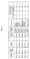
Fig. 2 illustrates a concrete example of the
transaction data registered in the IC card 10 according to
the present embodiment. The transaction data illustrated
in Fig. 2 includes five pieces of information. The first
account information relates to an account of A branch office
of A bank (an account number of 1111111) and the second account
information relates to an account of B branch office of A
bank (an account number of 2222222). The third account
information relates to an account of A branch office of B
bank (an account number of 1234567), the forth account
information relates to an account of B branch office of B
bank (an account number of 9876543), and the fifth account
information relates to an account of A branch office of C
bank (an account number of 1122334).
Further, the purposes of use for the respective
accounts are set and registered. In the example illustrated
in Fig. 2, the purpose of use for the first account is set
to "a salary account" (an account to which salary is
transferred), the purpose of use for the second account is
set to "a travel expenses account", the purpose of use for
the third account is set to "rent withdrawal"(an account
from which rent is withdrawn), the purpose of use for the
forth account is set to "public utility charges
withdrawal"(an account from which public utility charges
are withdrawn), and the purpose of use for the fifth account
is set to "sending money"(an account for sending money),
Further, in the example illustrated in Fig. 2, for
the respective items (pay, deposit and balance inquiry),
"1" is set for valid items while "0" is set for invaliditems.
Thus, transactable items are set for each account. Namely,
items for which "1" is set are transactable items while
executions of items for which "0" is set are restricted
(transaction-restricted items). More specifically, for
the first and second accounts, all of the items are set to
transactable items, while for the third to fifth accounts
two items, which are deposit and balance inquiry, are set
to transactable items and the other items are set to
transaction-restricted items.
On the other hand, the automatic machine (automatic
deposition payment machine, ATM, transaction machine) 20
executes predetermined transactions based on the
transaction data registered in the IC card 10 and is
configured to include a control section 21, an IC-card unit
22, a customer-side display LCD 23, a customer operation
touch panel 24, a personnel-side display LCD 25, a personnel
operation touch panel 26, a paper-money unit 27, a coin unit
28, a passbook unit 29, a receipt printer 30 and a journal
printer 31.
The IC-card unit (communicating section) 22 is adapted
for receiving and sending data from and to the IC card 10.
The customer-side LCD (Liquid Crystal Display) 23
functions as a display section for displaying various types
of information (an initial screen which will be described
later, the account selection screen, the item selection
screen, etc) to be referred to by the user when he executes
predetermined transactions by the ATM 20.
The customer operation touch panel (an input section,
a changing means) 24 is provided on the screen of the
customer-side display LCD 23 and functions as an input
section for enabling the user to push and input information
required for executing predetermined transactions while
referring to the customer-side display LCD 23. Further,
the customer operation touch panel 24 is used by the user
for inputting changes when he changes the purposes of use
and the transactable items, as will be described later.
The personnel-side display LCD 25 displays various
types of information to be referred to by personnel when
he performs maintenance of the ATM 20 or replenishes paper
money, coins or receipt paper. The personnel operation
touch panel 26 is provided on the screen of the personnel-side
display LCD 25 and is adapted for enabling personnel to push
and input information required for performing the
aforementioned maintenance or replenishment while
referring to the personnel-side display LCD 25.
The paper-money unit 27 is a unit for paying/receiving
paper money and the coin unit 28 is a unit for paying/receiving
coins. The passbook unit 29 is a unit for printing passbooks,
and the receipt printer 30 is a unit for printing receipts.
The journal printer 31 is a unit for printing journals.
The control section 21 controls collectively the
overall operation of the ATM 20. Particularly, in order
to realize characteristic operations of the present
invention, the control section 21 includes an ATM reference
area 21a and functions as a display control section 21b,
a transaction executing section 21c, a changing means 21d
and a writing means 21e.
The ATM reference area 21a is an area into which the
transaction data read out from the IC card 10 through the
IC-card unit 22 is written and is actually a storage area
in a RAM (Random Access Memory).
The
display control section 21b controls the display
state of the
LCD 23 based on the transaction data read out
from the IC card 10 through the IC-
card unit 22 and information
input from the
touch panel 24. More specifically, the
display control section 21b performs the following display
controls (1) to (3).
The transaction executing section 21c executes
predetermined transactions based on the account information
included in the transaction data in the ATM reference area
21a and information input from the touch panel 24.
Further, the changing means 21d and the writing means
21e function in the second aspect and the third aspect which
will be described later. The changing means 21d changes
the purposes of use and the transaction type information
based on information input through touch panel 24 by the
user. Further, the writing means 21e writes the purposes
of use or the transaction type information changed by the
touch panel 24 and the changing means 21d into the IC card
10 through the IC-card unit 22.
At this time, the display control section 21b causes
the LCD 23 to display a setting change key for commanding
changes of the purposes of use or the transaction type
information (see Fig. 11). When the user designates the
setting change key through the touch panel 24, the display
control section 21b causes the LCD 23 to display a setting
change screen (see Fig. 13 to Fig. 16). The user inputs
changes of the purposes of use or the transaction type
information using the touch panel 24 by referring to the
setting change screen and the changing means 21d changes
the purposes of use and the transaction type information
in the ATM reference area 21a, based on the input changes.
Here, the control section 21 is constituted by, for
example, a CPU (Central Processing Unit), RAMs and ROMs,
etc., and the CPU executes predetermined programs to realize
the functions of the display control section 21b, the
transaction executing section 21c, the changing means 21d
and the writing means 21e which have been described above.
The aforementioned programs are provided in the form of
programs recorded in a computer-readable recording medium
such as a flexible disk, a CD-ROM, a CD-R, a CD-RW, a DVD,
etc. In this case, the CPU reads out the aforementioned
programs from the recording medium, then transfers them to
an internal storage device or an external storage device
and stores them therein for use. Also, the programs may
be recorded in a storage device (recording medium) such as
a magnetic disk, an optical disk, and a magnetic optical
disk and may be provided from the storage device to the CPU
through a communication line.
[2] The operation of the present embodiment
[2-1] First Aspect
Fig. 3 is a flow chart for explaining the first aspect
of the operation of the ATM (transaction machine) 20
according to the present embodiment. Fig. 4 is a view
illustrating an initial screen (item selection screen)
according to the first aspect. Figs. 5 to 7 are views
illustrating account selection screens according to the
first aspect. Fig. 8 and Fig. 9 are views illustrating item
selection screens (transaction selection screens)
according to the first aspect.
In the first aspect, with reference to Fig.4 to Fig.
9, according to the flow chart (steps S10 to S28) illustrated
in Fig. 3, there will be described the operation of the ATM
20 (control section 21) in the case where the changing means
21d and the writing means 21e do not function and the user
can not change the purposes of use and the transactable items
through the ATM 20.
When the insertion of the IC card 10 being awaited,
an item selection screen illustrated in Fig. 4 is displayed
on the LCD 23 of the ATM 20 as the initial screen (step S10).
In the item selection screen illustrated in Fig. 4, there
are displayed six selection keys which are pay, deposit,
update of passbook, balance inquiry, pay by transfer and
transfer are displayed and when the user pushes the display
area of each selection key, the item (transaction type) of
the pushed area is selected by the function of the touch
panel 24.
When a selection key is pushed to select an item at
the state where the item selection screen is displayed (the
YES route of step S11), the insertion of the IC card 10 is
waited (NO route of step S12). When the IC card 10 is inserted
(YES route of step S12), the IC-card unit 22 in the ATM 20
sends a data-reading request to the IC card 10 and the
transaction data (IC-card data) illustrated in Fig. 2 is
read out from the storage section 12 in the IC card 10 and
stored in the ATM reference area 21a (step S13).
Then, by referring to the transaction data in the ATM
reference area 21a, the display control section 21b edits
an account selection screen based on the transaction data
and the item selected by the user and causes the LCD 23 to
display the account selection screen (step S14). For
example, when pay is selected as an item in the state where
the transaction data illustrated in Fig. 2 is stored in the
ATM reference area 21a, the display control section 21b
classifies the accounts into accounts for which pay is set
to valid "1" (namely, accounts for which pay is set as a
transactable item) and accounts for which pay is set to
invalid "0" (namely, accounts for which the transaction of
pay is restricted) . Then, the display control section 21b
edits an account selection screen in which these two types
of accounts (account information) are clarified (see, for
example, Fig. 5) and causes the LCD 23 to display the account
selection screen. Further, in the account selection screen
illustrated in Fig. 5, the contents of use for the respective
accounts are displayed along with the account information
(the names of banks/branch offices and account numbers) and
in addition, a restriction releasing key for releasing the
aforementioned restriction on transactions (the
restriction on selections) is displayed. While in the
account selection screen illustrated in Fig. 5 the account
information for the transactable accounts and the account
information for the accounts for which transactions are
restricted are displayed such that they are classified, only
the account information for transactable accounts may be
displayed and the account information for accounts for which
transactions are restricted may not be displayed in the
account selection screen.
After the account selection screen as illustrated in
Fig. 5 is displayed, when the user designates the restriction
releasing key through the touch panel 24, namely when the
user pushes the display area of the restriction releasing
key (YES route of step S15), the display control section
21b edits an account selection screen in which the selection
keys for all the accounts included in the transaction data
are selectable (see, for example, Fig. 6) and causes the
LCD 23 to display it (step S16) . Thus, an account selection
screen as illustrated in Fig. 6 is displayed on the LCD 23,
instead of the account selection screen as illustrated in
Fig. 5. Thus, by referring to the account selection screen
as illustrated in Fig. 6 and taking account of the contents
of use for the respective accounts, the user selects an
account for which the transaction of the selected item (pay
in this case) is to be executed, from all the accounts (step
S17).
When the user designates the selection key for an
account for which the transaction is to be executed, namely
when the user pushes the display area of the selection key
to select an account for which the transaction is to be
executed (YES route of step S17), the transaction executing
section 21c starts and executes the transaction of the
selected item for the selected account (step S19). The
transaction processes from then on is similar to conventional
processes and the explanation thereof will be omitted. When
this transaction process is terminated, the process returns
to step S10.
Also, when the user does not push the restriction
releasing key (NO route of step S15) and then selects an
account for which the transaction is to be executed from
the transactable accounts by referring to the account
selection screen as illustrated in Fig. 5 and taking into
account the contents of use for the respective transactable
accounts (two account in Fig.5) (YES route of step S18),
the transaction executing section 21c starts and executes
the transaction of the selected item for the selected account
similarly to previously described (step S19). Then, the
process returns to step S10.
On the other hand, in the case where the user inserts
the IC card 10 into the ATM 20 before selecting an item (in
the case where the insertion of the card precedes; NO route
of step S11 and YES route of step S20), the IC-card unit
22 in the ATM 20 sends a data-reading request to the IC card
10 and the transaction data (IC-card data) illustrated in
Fig. 2 is read out from the storage section 12 in the IC
card 10 and stored in the ATM reference area 21a, similarly
to the aforementioned step S13 (step S21).
Subsequently, by referring to the transaction data
in the ATM reference area 21a, the display control section
21c edits an account selection screen for displaying
information about all the accounts included in the
transaction data (information including the account
information (the names of banks/branch offices and the
account numbers), the purposes of use (the contents of use),
and the transactable items) (see Fig. 7). Then, the display
control section 21a causes the LCD 23 to display the account
selection screen (step S22). In the account selection
screen, as illustrated in Fig. 7, a restriction releasing
key for releasing the restriction on transactions
(restriction on selections) is further displayed. In the
case where the information about all accounts cannot be
displayed in a single screen (account selection screen),
a next-screen key is provided and when the user pushes the
next-screen key, information, which could not be displayed
in a single screen, is displayed in the next screen.
In the state where the account selection screen
illustrated in Fig.7 is displayed, when the user pushes the
restriction releasing key (YES route of step S23) and then
selects an account for which a transaction is to be executed,
from all the accounts in the account selection screen
illustrated in Fig. 7, by referring to the purposes of use
(the contents of use) (YES route of step S24), the display
control section 21b causes the selection keys for all items
to be displayed in the item selection screen as illustrated
in Fig.8 (step S25). In the item selection screen
illustrated in Fig. 8, similarly to the initial screen, six
selection keys, which are pay, deposit, update of passbook,
balance inquiry, pay by transfer and transfer, are displayed.
In the state where the account selection screen
illustrated in Fig.7 is displayed, when the user does not
push the restriction releasing key (NO route of step S23)
and then selects an account for which a transaction is to
be executed, from all accounts in the account selection
screen illustrated in Fig. 7 by referring to the purposes
of use (the contents of uses) and the transactable items
(YES route of step S26), the display control section 21b
causes only the selection keys for items preset for the
selected account to be displayed in the item selection screen,
as illustrated in Fig.9 (step S27). The item selection
screen illustrated in Fig. 9 corresponds to the case where
the account of A branch office of C bank (the fifth account)
is selected in the account selection screen illustrated in
Fig.7. In the item selection screen, only two selection
keys for deposit and balance inquiry, which are set as
transactable item for the account, are displayed.
When the user selects, by referring to the item
selection screen displayed at step S25 or step S27, an account
from the screen (YES route of step S28), the transaction
executing section 21c starts and executes the transaction
of the selected item for the selected account, similarly
to previously described (step S19). Then, the process
returns to step S10.
[2-2] Second Aspect
Fig. 10 is a flow chart for explaining the second aspect
of the operation of the ATM (transaction machine) 20
according to the present embodiment. Fig.11 is a view
illustrating an initial screen (item selection screen) in
the second aspect. Figs. 12 to 16 are views illustrating
setting change screens in the second aspect.
In the second aspect, with reference to Fig.11 to
Fig.16, according to the flow chart (steps S30 to S54)
illustrated in Fig. 10, there will be described the operation
of the ATM 20 in the case where the changing means 21d and
the writing means 21e function and the user can change the
purposes of use (the contents of use) and the transactable
item through the ATM 20 (control section 21).
When the insertion of the IC card 10 being awaited,
the item selection screen illustrated in Fig. 11 is displayed,
as an initial image plane, on the LCD 23 of the ATM 20 (step
S30). In the item selection screen illustrated in Fig.11,
similarly to the item selection screen in Fig.4, six
selection keys, which are pay, deposit, update of passbook,
balance inquiry, pay by transfer and transfer, are displayed
and a setting change key for commanding changes of the
purposes of use (the contents of use) and the transactable
item is further displayed. When the user pushes the display
area of each key, the item or the setting changing function
of the pushed area is selected by the function of the touch
panel 24.
When a key out of the seven keys is pushed in the state
where the initial screen is displayed (YES route of step
S31), the insertion of the IC card 10 is wait (NO route in
step S32). When the IC card 10 is inserted (YES route of
step S32), the IC-card unit 22 in the ATM 20 sends a
data-reading request to the IC card 10 and the transaction
data (IC-card data) illustrated in Fig. 2 is read out from
the storage section 12 in the IC card 10 and stored in the
ATM reference area 21a (step S33). Then, at step S38, it
is determined whether or not the key pushed in the
aforementioned initial screen is the setting change key.
On the other hand, in the case where the user inserts
the IC card 10 into the ATM 20 before selecting and pushing
a key in the initial screen (in the case where the insertion
of the card precedes; NO route of step S31 and YES route
of step S34), the IC-card unit 22 in the ATM 20 sends a
data-reading request to the IC card 10 and the transaction
data (IC-card data) illustrated in Fig. 2 is read out from
the storage section 12 in the IC card 10 and stored in the
ATM reference area 21a similarly to the aforementioned step
S33 (step S35). At this time, in the second aspect, the
initial screen illustrated in Fig.11 is continuously
displayed on the LCD 23 (step S36) and when a key of the
seven keys is pushed in the initial screen (YES route of
step S37), it is determined whether or not the pushed key
is the setting change key (step S38).
When it is determined, at step S38 that the pushed
key is an item selection key, not the setting change key
(NO route), the processes steps S39 to S44 are executed.
Steps S39 to S44 are similar to steps S14 to S19 in Fig.
3 and therefore the explanation thereof will be omitted.
When the transaction process at step S44 has ended, the
process returns to step S30.
When it is determined, at step S38, that the setting
change key has been pushed (YES route), the display control
section 21b edits, by referring to the transaction data in
the ATM reference area 21a, an account selection screen
(setting change screen) for selecting an account for which
the setting is to be changed and causes the LCD 23 to display
the account selection screen (step S45). In the account
selection screen, for example, as illustrated in Fig. 12,
the account information (the names of banks/branch offices
and the account numbers) and the contents of use for all
accounts included in the transaction data in the ATM
reference area 21a are displayed.
When the user selects an account for which the setting
is to be changed, from among all the accounts in the account
selection screen illustrated in Fig.12, by referring to the
purposes of use (the contents of uses) (YES route of step
S46), the display control section 21b edits, by referring
to the transaction data in the ATM reference area 21a, an
item change screen (setting change screen) or a use change
screen (setting change screen) including the information
about the selected account and causes the LCD 23 to display
it (step S47) .
Here, in the item change screen, for example, as
illustrated in Fig.13, the current transactable items and
the current content of use (the purpose of use) for the
selected account are displayed by text and the selection
keys for all the items, a use changing key for switching
to the use change screen illustrated in Fig. 14 and a
confirmation key for confirming changes are displayed.
Specifically, in the example illustrated in Fig. 13, "salary
account" is set as the content of use and pay and deposit
are set as transactable items. In the item change screen,
the selection keys set for transactable items are displayed
in a different state from the selection keys which are not
set for the transactable items. In Fig.13, the selection
keys set for transactable items are hatched. In an actual
display screen, for example, the selection keys set for
transactable items are displayed in a gray color indicating
the pushed state, while the selection keys which are not
set for transactable items are displayed in a blue color
indicating the un-pushed state. In the item change screen,
when any of the selection keys set for transactable items
is pushed a single time, the selection key is changed to
the state where it is not set for a transactable item, and
on the contrary when any of the selection keys which are
not set for transactable items is pushed a single time, the
selection key is changed to the state where it is set for
a transactable item.
Further, in the use change screen, for example, as
illustrated in Fig.14, the current content of use (purpose
of use) for the selected account is displayed by text and
the selection keys for all contents of use (purposes of uses),
an item changing key for switching to the item change screen
illustrated in Fig. 13 and a confirmation key for confirming
changes are displayed. Specifically, in the example
illustrated in Fig. 14, "salary account" is set as the content
of use. In the use change screen, the selection keys set
for the contents of use and the selection keys which are
not set for the contents of use are displayed in different
states. In Fig. 14, the selection keys which are currently
set for the contents of use are hatched. In an actual display
screen, for example, the selection keys which are currently
set for the contents of use are displayed in a gray color
indicating the pushed state, while the other keys are
displayed in a blue color indicating the un-pushed state.
In the use change screen, when any of the selection keys
set for the contents of use is pushed a single time, the
selection key is changed to the state where it is not set
for a transactable item, and on the contrary when any of
the selection keys which are not set for the contents of
use is pushed a single time, the selection key is changed
to the state where it is set for the content of use. In
the case where only a single item is set as the content of
use, when a selection key which is not set for the content
of use is pushed a single time, the selection key is switched
to the state where it is set for the content of use and
concurrently the selection key which has been set for the
content of use is switched to a selection key which is not
set for the use content.
At a step S47, depending on the use changing key or
the item changing key which was pushed, one of the
aforementioned item change screen and the use change screen
is displayed on the LCD 23 and the content of use or the
transactable items for the selected account is changed.
At this time, the transaction data in the form
illustrated in Fig.2 is stored in a work area (not shown;
for example, an area in a RAM) and the changing means 21d
reverses the validity "1"/invalidity "0" of the transactable
items in the transaction data in the work area and changes
the contents of use (the purposes of use) in the transaction
data in the work area, depending on the aforementioned
switching pushing operation.
When the contents of use and the transactable items
have been changed and the confirmation key in the item change
screen or the use change screen has been pushed (YES route
of step S48), the display control section 21b causes the
LCD 23 to display a correction/confirmation screen (setting
change screen) (step S49). In the correction/confirmation
screen, for example, as illustrated in Fig.15, the content
of changes (the transactable items and the contents of use
after changing) is displayed by text and a confirmation key
which is pushed for correcting the content of changes and
a correction key which is pushed for correcting the content
of changes are displayed.
When the user pushes the correction key in the
correction/confirmation screen ("correction" route of step
S50), the process returns to step S45 and the same processes
are repeatedly executed. On the other hand, when the user
pushes the confirmation key in the correction/confirmation
screen ("confirmation" route of step S50), the display
control section 21b causes the LCD 23 to display a
continue/confirmation screen (setting change screen) (step
S51). In the continue/confirmation screen, for example,
as illustrated in Fig. 16, a confirmation key which is pushed
for terminating the setting changing process and a continue
key which is pushed for continuously executing the setting
changing process are displayed.
When the user pushes the continue key in the
continue/confirmation screen ("continue" route of step S52),
the process returns to step S45 and the same processes are
repeatedly executed. On the other hand, when the user pushes
the confirmation key in the continue/confirmation screen
("confirmation" route of step S52), the writing means 21e
causes a data rewriting request to be sent to the IC card
10 from the IC-card unit 22 in the ATM 20 and the transaction
data in the storage section 12 in the IC card 10 corresponding
to the data rewriting request is rewrittenbased on the change
information in the aforementioned work area (step S53).
Subsequently, the content of changes is printed on a receipt
and journal by the receipt printer 30 and the journal printer
31, and then the receipt and the IC card 10 are returned
to the user (step S54) . Then, the process returns to step
S10.
[2-3] Third Aspect
Fig. 17 is a flow chart for explaining the third aspect
of the operation of the ATM 20 according to the present
embodiment and Fig.18 is a view illustrating an initial
screen (card insertion commanding screen) according to the
third aspect.
In the third aspect, basically, the process is executed
with the same procedure as that of the second aspect. However,
in the third aspect, as the initial screen, instead of the
item selection screen as in the second aspect (see Fig.1),
the card insertion commanding screen as illustrated in Fig. 18
is displayed on the LCD 23 of the ATM 20 (step S60 in Fig.
17). When the user refers to the card insertion commanding
screen and inserts the IC card 10 into the ATM 20 (the IC-card
unit 22) (YES route of step S61), the process proceeds to
step S35 in Fig. 10 and the same processes as those (steps
S35 to S54) of the second aspect are executed.
[3] The Effects of the Invention
As described above, with the IC card 10 and the ATM
20 according to an embodiment of the present invention, by
registering, beforehand, the purposes of use for respective
accounts (respective transactions) in the storage section
12 in the IC card 10, the purposes of use are displayed on
the LCD 23 of the ATM 20 along with the account information
(the name of bank/branch office and the account number) when
transactions using the IC card 10 are to be executed. Thus,
the user can recognize the purposes of use of the respective
accounts at a glance and can select an account by referring
to the purposes of use. This certainly prevents the user
from erroneously selecting an unintended account.
Further, by registering, beforehand, transactable
items in the storage section 12 of the IC card 10, the
information about the transactable items is reflected on
the account selection screen and the item selection screen
in the ATM 20 to restrict the selection of items for the
respective accounts (transaction types), when transactions
using the IC card 10 are to be executed. This certainly
prevents the user from erroneously selecting items which
are not intended by the user.
At this time, the transactable items for the respective
accounts are displayed as illustrated in Fig. 7 and thus
the user can certainly recognize the transactable items for
the respective accounts. This certainly prevents the user
from erroneously selecting wrong items for the selected
account.
Further, for example, the selection keys for accounts
for which an item designated by the user is set as a
transactable item may be clearly displayed in the account
selection screen as illustrated in Fig.5 or, for example,
only the selection keys for transactable items set for an
account designated by the user may be displayed in the
transaction selection screen as illustrated in Fig.9,
thereby easily and certainly restricting the selection of
items for the respective accounts. At this time, as
illustrated in Fig. 5 and Fig.7, the restriction releasing
key can be displayed and, when the restriction releasing
key is designated, all the selection keys can be made
selectable and displayed (see Fig. 6 and Fig.8). Therefore,
even when the selection is restricted in the account
selection screen or the item selection screen, the
restriction on selections can be released as required by
the user and the user can freely select transaction types,
thereby improving the convenience.
Further, the user can cause the setting change screen
(see Fig.12 to Fig.16) to be displayed using the setting
changing key (see Fig.11) in the ATM 20. Then the user can
change the contents of use and the transactable items by
referring to the setting change screen and can write them
into the storage section 12 in the IC card 10. Therefore,
the user can freely change the contents of use and the contents
of transactable items (the restriction on selection) and
reset them in the IC card 10 as required, thereby improving
the convenience.
[4] Others
The present invention is not limited to the
aforementioned embodiment and can be implemented by making
various modifications thereto without departing from the
spirit of the present invention.
For example, while in the aforementioned embodiment
there have been described cases where transactions are
financial transactions (deposit, pay, update of passbook,
balance inquiry, pay by transfer, or transfer) using accounts
of financial institutions, the present invention is not
limited to this and can be applied to various types of
electronic commercial transactions similarly to the
aforementioned embodiment to obtain similar effects.
Further, while in the aforementioned embodiment there
have been described cases where the portable storage device
is an IC card, the present invention is not limited to this
and can be applied to any portable device having a storing
function such as magnetic cards, optical cards, bio-cards,
portable phones, or PDAs (Personal Digital Assistants) to
achieve the same effects as those of the aforementioned
embodiment.
Industrial Applicability
As described above, with the present invention, by
registering intended use information for respective
transactions or respective accounts beforehand, the
intended use information can be displayed in the selection
screen on the transaction machine when transactions are
executed using the portable storage device, which can
certainly prevent transactions or selections of accounts
which are not intended by the user from being executed.
Therefore, the present invention is suitable for
systems which execute transactions such as deposition,
payment, balance inquiry, payment by transfer or transfer
using an IC card in which plural account information is
registered in advance and the convenience thereof is
extremely high.