EP1598520A1 - Downhole recorder system - Google Patents
Downhole recorder system Download PDFInfo
- Publication number
- EP1598520A1 EP1598520A1 EP04291275A EP04291275A EP1598520A1 EP 1598520 A1 EP1598520 A1 EP 1598520A1 EP 04291275 A EP04291275 A EP 04291275A EP 04291275 A EP04291275 A EP 04291275A EP 1598520 A1 EP1598520 A1 EP 1598520A1
- Authority
- EP
- European Patent Office
- Prior art keywords
- assembly
- sub
- downhole
- recorder
- operating data
- Prior art date
- Legal status (The legal status is an assumption and is not a legal conclusion. Google has not performed a legal analysis and makes no representation as to the accuracy of the status listed.)
- Granted
Links
- 238000000034 method Methods 0.000 claims description 18
- 238000012423 maintenance Methods 0.000 claims description 14
- 238000012545 processing Methods 0.000 claims description 13
- 238000004519 manufacturing process Methods 0.000 claims description 9
- 238000005553 drilling Methods 0.000 claims description 7
- 238000000429 assembly Methods 0.000 description 20
- 230000015654 memory Effects 0.000 description 17
- 238000012360 testing method Methods 0.000 description 13
- 230000000875 corresponding effect Effects 0.000 description 10
- 230000015572 biosynthetic process Effects 0.000 description 4
- 238000005259 measurement Methods 0.000 description 4
- 230000002596 correlated effect Effects 0.000 description 3
- 230000035939 shock Effects 0.000 description 3
- 230000008901 benefit Effects 0.000 description 2
- 239000003381 stabilizer Substances 0.000 description 2
- 206010011906 Death Diseases 0.000 description 1
- 230000003247 decreasing effect Effects 0.000 description 1
- 230000006870 function Effects 0.000 description 1
- 239000007788 liquid Substances 0.000 description 1
Images

Classifications
-
- E—FIXED CONSTRUCTIONS
- E21—EARTH DRILLING; MINING
- E21B—EARTH DRILLING, e.g. DEEP DRILLING; OBTAINING OIL, GAS, WATER, SOLUBLE OR MELTABLE MATERIALS OR A SLURRY OF MINERALS FROM WELLS
- E21B47/00—Survey of boreholes or wells
- E21B47/26—Storing data down-hole, e.g. in a memory or on a record carrier
Definitions
- the invention relates generally to downhole recorders for use with a downhole assembly.
- a downhole assembly is used within a borehole, for example for drilling the borehole itself, or for characterizing a formation surrounding the borehole.
- the downhole assembly when lowered into the borehole, may be subject to extreme conditions, e.g. high pressures, high temperatures.
- the downhole assembly may subsequently be worn down or damaged. Maintenance operations are hence performed on the downhole assembly.
- operating data e.g. a date of repair, a nature of the repair, a peak of temperature measured downhole
- the writing of the operating data allows to constitute a database of the operating data.
- a lifetime of the downhole assembly or of a sub-assembly of the downhole assembly may be evaluated from the operating database.
- Sensors located downhole allow to perform measurements of environment parameters, e.g. temperature, shock events, vibration events, humidity rate, number of ON/OFF cycles, pressure, supply voltage and currents, flow rate of a liquid, rotating velocity of a collar of the downhole assembly.
- environment parameters e.g. temperature, shock events, vibration events, humidity rate, number of ON/OFF cycles, pressure, supply voltage and currents, flow rate of a liquid, rotating velocity of a collar of the downhole assembly.
- the sensors are traditionally read at surface following a raising operation.
- a recorder mounted on the downhole assembly allows to provide a downhole storage of the operating data.
- the sensors are connected to the recorder and measured environment data are written into the recorder.
- the recorder When the downhole assembly is raised up to a surface, the recorder is read and at least a portion of a content of the recorder is transferred into a computer.
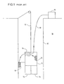
- FIG. 1 illustrates an example of a downhole assembly from prior art.
- the downhole assembly 11 is lowered into a borehole 12.
- the downhole assembly 11 is lowered by means of a wireline cable 17.
- the downhole assembly 11 comprises a logging tool (not represented) allowing to characterize a formation 18 surrounding the borehole 12.
- Sensors 13 allow to measure environment data that are subsequently written into a recorder 15.
- the measured environment data may be read at the recorder when the downhole assembly is raised to the surface.
- an electrical cable 19 allows to read the measured environment data from a computer 16 located at the surface.
- An operating database may be constructed from the read environment data and from maintenance data stored either in the recorder 15 or directly in the computer 16.
- a lifetime of the downhole assembly 11 may be evaluated from the operating database, according to a reliability model.
- the downhole assembly 11 usually comprises at least one sub-assembly 14, e.g. a collar (not represented), a drill bit (not represented).
- the sensors 13 themselves may also be considered as a sub-assembly.
- the computer 16 may allow to evaluate a lifetime of each one of the sub-assemblies 14.
- a plurality of sub-assembly reliability models, each sub-assembly reliability model allowing to evaluate the lifetime of a determined sub-assembly, may be used for that purpose.
- the invention provides a downhole recorder system for use with a downhole assembly to be lowered into a borehole.
- the downhole recorder system comprises at least one recorder uniquely associated to a determined sub-assembly of the downhole assembly.
- the at least one recorder allows to store operating data related to the determined sub-assembly.
- the stored operating data are extractable at least when the determined sub-assembly is disassembled from the downhole assembly.
- the operating data comprise environment data relating to at least one environment parameter.
- the operating data comprise maintenance data.
- the operating data comprise manufacturing data.
- At least one common sensor communicates with more than one recorder.
- a common sensor allows to measure an environment parameter.
- the downhole recorder system further comprises at least one sub-assembly sensor, a sub-assembly sensor being attached to a specific sub-assembly.
- the sub-assembly sensor allows to measure an environment parameter.
- the measured environment parameter is stored by the recorder associated to the sub-assembly corresponding to the sub-assembly sensor.
- the downhole recorder system further comprises at least one integrated sensor, an integrated sensor being part of a recorder among the at least one recorders.
- the integrated sensor allows to measure an environment parameter.
- a controller communicates with each recorder.
- processing means are located at a surface.
- the processing means allow to analyze the stored operating data.
- the downhole recorder system further comprises downloading means to download the stored operating data from a recorder to the processing means.
- the invention provides a method for tracking at least one sub-assembly of a downhole assembly with a downhole recorder system.
- the method comprises individually storing operating data for a determined sub-assembly.
- the stored operating data are individually extractable.
- a value an environment parameter is measured.
- the method further comprises individually storing as environment data the measured value.
- the method further comprises individually storing maintenance data relating to a maintenance operation performed at the determined sub-assembly.
- the individually stored operating data are downloaded.
- the downloaded operating data are processed to determine a lifetime of the determined sub-assembly, according to a corresponding sub-assembly reliability model.
- the at least one sub-assembly reliability model is adjusted a posteriori with the downloaded operating data.
- the invention provides a wireline system for use in a borehole.
- the wireline system comprises at least one sub-assembly and a downhole recorder system according to the first aspect of the invention.
- the invention provides a drilling machine for use in a borehole.
- the drilling machine comprises at least one sub-assembly and a downhole recorder system according to the first aspect of the invention.
- FIG. 1 illustrates an example of a downhole assembly from prior art.
- FIG. 2 illustrates an example of a downhole assembly according to a first embodiment of the present invention.
- FIG. 3 illustrates an example of a downhole assembly according to a second embodiment of the present invention.
- FIG. 4 is a flowchart illustrating an example of a method for recording environment data according to a third embodiment of the present invention.
- FIG. 5 illustrates an example of an algorithm for tracking a plurality of sub-assemblies according to a fourth embodiment of the present invention.
- a downhole assembly may be tracked so as to allow an evaluating of a state of the downhole assembly.
- a recorder is provided to store operating data in a non-volatile memory.
- An operating database may be constructed from the operating data: the operating database allows to evaluate a lifetime of the downhole assembly.
- the downhole assembly typically comprises at least one sub-assembly.
- a determined sub-assembly may be replaced several times due to a shorter lifetime of the determined sub-assembly as compared to a lifetime of the downhole assembly or of other sub-assemblies of the downhole assembly.
- a new sub-assembly may be inserted, e.g. a new sensor.
- the downhole assembly may also be dismantled and a sub-assembly may be reused in a distinct downhole assembly.
- the operating data are stored in a single recorder: in any one of those latter cases, the operating data relative to a displaced sub-assembly may be lost.
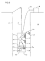
- FIG. 2 illustrates an example of a downhole assembly according to a first embodiment of the present invention.
- a downhole recorder system comprises at least one recorder (25a, 25b) uniquely associated to a determined sub-assembly (24a, 24b) of the downhole assembly 21.
- the at least one recorder (25a, 25b) allows to store operating data related to the determined sub-assembly (24a, 24b). The stored operating data are extractable at least when the determined sub-assembly is disassembled from the downhole assembly.
- a determined sub-assembly (24a, 24b) is disassembled from the downhole assembly 21, e.g. for a disposal or for a further use within a distinct downhole assembly
- the operating data stored into the associated recorder (25a, 25b) may be extracted to follow the determined sub-assembly (24a, 24b).
- the present invention hence provides an individualized storing of the operating data for the determined sub-assembly (24a, 24b).
- a tracking of the determined sub-assembly is rendered easier than in the systems from prior art wherein operating data relative to the determined sub-assembly and to other parts of the downhole assembly are stored within a single recorder.
- the downhole assembly may comprise a single sub-assembly.
- the downhole recorder system comprises a recorder that is uniquely associated to the single sub-assembly. Operating data for the single sub-assembly are individually stored within the recorder. If the single sub-assembly is disassembled from the downhole assembly, the recorder may be extracted to follow the single sub-assembly.
- the downhole assembly may also comprise a plurality of sub-assemblies (24a, 24b) and a plurality of recorders (25a, 25b).
- Each recorder (25a, 25b) is uniquely associated to a determined sub-assembly (24a, 24b) among the plurality of sub-assemblies (24a, 24b).
- Operating data for each determined sub-assembly (24a, 24b) are individually stored within the associated recorder (25a, 25b).
- the operating data stored into a determined recorder (25a, 25b) are individually extractable.
- the recorders (25a, 25b) may be for example part of the associated sub-assemblies (24a, 24b).
- the recorders are attached to the associated sub-assemblies.
- the recorders may also be grouped into a recorder tool located downhole, at a relatively high distance from the associated sub-assemblies.
- the operating data typically comprise environment data, i.e. measurements of environment parameters.
- the environment parameters may be for example temperature, shock events, vibration events, and humidity rate.
- the environment data are measured at a sensor (23, 29, 210).
- the sensor may be a common sensor 23 communicating with more than one recorder.
- the common sensor 23 allows to measure an environment parameter.
- the environment parameter is correlated to lifetimes of a plurality of sub-assemblies and the environment parameter may be substantially uniform over a length of the downhole assembly.
- the sensor may also communicate with a single recorder, in particular if an environment parameter to be measured by the sensor varies a lot with a distance to the associated sub-assembly.
- the environment parameter to be measured by the sensor may also be of particular interest for the associated sub-assembly only.
- a controller 211 communicates with the plurality of recorders (25a, 25b).
- the common sensors 23 may communicate with the corresponding recorders (25a, 25b) via the controller 211.
- the sensor may also be a sub-assembly sensor 29 that is attached to a specific sub-assembly 24b.
- the sub-assembly sensor 29 allows to measure an environment parameter.
- the measured environment parameter is stored within the recorder 25b associated to the sub-assembly 24b corresponding to the sub-assembly sensor 29.
- the sensor may also be an integrated sensor 210 that is part of a recorder 25a among the at least one recorders (25a, 25b).
- the integrated sensor 210 allows to measure an environment parameter.
- the integrated sensor 210 is a micro-sensor having a relatively small size.
- the integrated sensor 210 may for example be a temperature sensor or a shock sensor.
- the system of the present invention may, as represented in FIG. 2 comprise a plurality of sensors (23, 29, 210) that communicate with one or more recorders (25a, 25b).
- the communicating may be in a single direction, i.e. from the sensors to the recorders, or in both directions, as represented in FIG. 2.
- the controller 211 may further comprise adjusting means to control the sensors (23, 29, 210): the adjusting means may for example allow to calibrate the sensors (23, 29, 210).
- the recorders (25a, 25b) are wired independently from other functions of the downhole assembly 21.
- the downhole assembly 21 comprises a logging tool (not represented on FIG. 2) allowing to measure logging data of a formation 28 surrounding the borehole 22
- a logging circuit (not represented on FIG. 2) may be provided for a transportation of the logging data either up to the surface or to a logging memory.
- Electrical wires 213 dedicated to the communicating with the recorder are independent from the logging circuit. The electrical wires 213 may even have a higher reliability than the logging circuit so as to insure that the operating data stored into the recorders (25a, 25b) are retrieved in a case of a failure of the logging tool. The stored operating data may be subsequently used for an analysis of the failure.
- the recorders, the sensors and the controller communicate with any other communicating means, e.g. electromagnetic waves.
- the recorders (25a, 25b) allow to store operating data.
- the operating data may be environment data measured at the sensors 23.
- the operating data may also comprise maintenance data, i.e. data relating to maintenance operations performed on the associated sub-assembly such as a nature of a repair, a time of the repair, a place of the repair etc.
- the operating data may also comprise manufacturing data, i.e. data relating to a manufacturing of the associated sub-assembly such as a time of manufacture.
- the system of the present invention may further comprise processing means 26 located at surface.
- the processing means 26 are typically constituted of a computer.
- the processing means 26 allow to analyze the operating data stored into the recorders (25a, 25b).
- Downloading means e.g. an electrical cable 212, allow to download the stored operating data from a recorder among the at least one recorders to the processing means 26.
- the downloading means may also be a telemetry system or any other system allowing to download the data from the recorders (25a, 25b).
- the downloading may be performed periodically or continuously.
- the downloading allows to construct an operating database at the computer.
- the operating database may be processed either automatically or on demand, to determine a life time of at least one sub-assembly (24a, 24b), according to a corresponding sub-assembly reliability model and according to further operating conditions.
- the downhole assembly 21 may be a wireline system, as in the example represented in FIG. 2.
- the wireline system is lowered into the borehole 22 by a wireline cable 27.
- the downhole assembly may be any other system located downhole.
- FIG. 3 illustrates an example of a downhole assembly according to a second embodiment of the present invention.
- the downhole assembly 31 is a drilling machine.
- the downhole assembly 31 comprises a plurality of sub-assemblies (34a, 34b, 34c, 34d, 34e).
- the plurality of sub-assemblies (34a, 34b, 34c, 34d, 34e) comprises a first stabilizer 34a, a second stabilizer 34c, a motor 34b, a collar 34d and a drill bit 34e.
- the drilling machine 31 allows to drill a borehole 32 into a formation 38.
- a plurality of recorders (35a, 35b, 35c, 35d, 35e) is provided, each recorder (35a, 35b, 35c, 35d, 35e) being associated to a determined sub-assembly (34a, 34b, 34c, 34d, 34e). Each recorder (35a, 35b, 35c, 35d, 35e) allows to store operating data.
- the operating data stored into a determined recorder (35a, 35b, 35c, 35d, 35e) are preferably correlated to a lifetime of the associated sub-assembly (34a, 34b, 34c, 34d, 34e).
- a plurality of sensors (33, 39a, 39b, 39c, 314) may be provided to measure environment data relating to environment parameters.
- a common sensor 33 communicating with more than one recorder (35d, 35e) may be provided.
- the common sensor 33 communicates directly with the more than one recorders (35d, 35e).
- Sub-assembly sensors (39a, 39b, 39c) are also represented on FIG. 3. Each sub-assembly sensor (39a, 39b, 39c) is attached to a specific sub-assembly (34a, 34b, 34c).
- a wireline sensor 314 may also be provided.
- the wireline sensor 314 may communicate with the recorder 39a for example via electromagnetic waves.
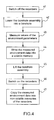
- FIG. 4 is a flowchart illustrating an example of a method for recording environment data according to a third embodiment of the present invention.
- the method illustrated in FIG. 4 allows to store measured environment data into a downhole recorder system comprising a plurality of recorders.
- a downhole assembly comprises a plurality of sub-assemblies. Each recorder is uniquely associated to a determined sub-assembly.
- the recorders comprise a non-volatile memory, e.g. an EEPROM that communicates with a volatile memory.
- a non-volatile memory e.g. an EEPROM that communicates with a volatile memory.
- a single volatile memory communicating with a plurality of non-volatile memories of the recorders may be provided.
- each non-volatile memory communicates with a dedicated volatile memory.
- the recorders are switched off (box 41) to avoid damaging.
- the downhole assembly is lowered into the borehole following the switching off (box 42).
- Sensors perform measurements of environments parameters (box 43).
- the measured environment data are written into the volatile memory (box 44).
- the volatile memory remains active even after the switching off of the recorders.
- the recorders are switched on (box 46).
- the downhole assembly may be lifted to a surface or to a zone of the borehole with less extreme conditions than a zone of measurements.
- the measured environment data are copied from the volatile memory to the non-volatile memory of the recorders (box 47).
- the lifting and the copying are typically performed at an end of a downhole operation executed by the downhole assembly while downhole.
- the volatile memory is subsequently re-initialized for a further downhole operation.
- the lifting and the copying of the measured environment data may be performed at regular intervals, e.g. every 10 minutes.
- the recorders remain active.
- the measured data are directly written from the sensors to the non-volatile memories of the recorders.
- Such a recording of measured environment data may be followed by a processing of the environment data so as to determine a lifetime of the sub-assemblies.
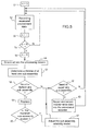
- FIG. 5 illustrates an example of an algorithm for tracking a plurality of sub-assemblies of a downhole assembly according to a fourth embodiment of the present invention.
- a downhole assembly comprises a plurality of sub-assemblies.
- a plurality of recorders is provided, each recorder allowing to individually record operating data for a determined sub-assembly among the plurality of sub-assemblies.
- the stored operating data are individually extractable, in particular if the determined sub-assembly is disassembled from the downhole assembly.
- the recording of the measured environment data may for example be performed following the method illustrated in FIG. 4, the method of the first alternative embodiment or the method of the second alternative embodiment.
- the recording (box 52) is performed several times before a downloading of the recorded operating data (box 56).
- a variable is reset at a beginning of an operation (box 51).
- the variable is incremented (box 53) following the recording (box 52).
- the variable is compared to a predetermined threshold (box 54). If the variable is smaller or equal to the predetermined threshold, the recording (box 52) and the incrementing of the variable (box 53) are repeated.
- variable is reset (box 55) and the measured environment data are downloaded into processing means, e.g. a computer (box 56), thus allowing to construct or upgrade an operating database.
- processing means e.g. a computer (box 56), thus allowing to construct or upgrade an operating database.
- the computer may allow to determine a lifetime of at least one sub-assembly (box 57).
- the resetting (box 55), the downloading (box 56) and subsequent steps may be performed upon an event such as a lifting of the downhole assembly.
- the resetting (box 55), the downloading (box 56) and subsequent steps may also be performed either upon a lifting of the downhole assembly or upon a result of a comparing of a variable (box 54).
- maintenance data, manufacturing data and/or any other data correlated to a state of a determined sub-assembly are stored within the associated recorder.
- the maintenance data and the manufacturing data may be also downloaded.
- the recorders contain data in a single data format so as to facilitate a reading of each recorder of the plurality of recorders.
- the operating database of a determined sub-assembly may be stored within a memory of the computer and within the associated recorder.
- a non-volatile memory of the associated recorder is partially erased after the downloading and the operating database is stored only into the memory of the computer.
- the associated recorder discloses only a portion of the operating database, typically recent data. If the determined sub-assembly is replaced or used within a distinct downhole assembly, particular care must be taken to the corresponding operating database, as the corresponding operating database is partially stored within the computer.
- the associated recorder hence preferably allows to store the whole operating database.
- the lifetime of the at least one sub-assembly is determined (box 57) according to a sub-assembly reliability model that involves parameters of the operating database.
- a sub-assembly reliability model of a determined sub-assembly may estimate the lifetime of the determined sub-assembly as exponentially decreasing with time and temperature.
- a time of manufacturing among the manufacturing data and data relating to temperatures and durations of exposures to high temperatures among the environment data allow to determine at least a probability of the lifetime of the determined sub-assembly.
- the determining of the lifetime is preferably performed for a plurality of sub-assemblies.
- a first test is performed to evaluate if any sub-assembly among the plurality of sub-assemblies needs to be replaced (box 58).
- the first test may consist in respectively comparing the determined lifetimes to a plurality of lifetime thresholds.
- the first test may also be performed with any other method such as a mechanical test, an electric test etc.
- a second test may be performed to evaluate if any sub-assembly needs to be repaired (box 62).
- the second test may consist in respectively comparing the determined lifetimes to a second plurality of lifetime thresholds. If for example a determined sub-assembly enters in an end-of-life period, there may be a need for replacing a piece of the sub-assembly, e.g. a seal.
- the second test may also be performed with any other method such as a mechanical test, an electric test etc.
- the determined sub-assembly is replaced (box 59).
- a third test may be performed to evaluate whether the replaced sub-assembly is broken or not (box 60). If the replaced sub-assembly is broken, i.e. the determined sub-assembly had an effective lifetime shorter than the determined lifetime, the corresponding sub-assembly reliability model may be adjusted a posteriori (box 61). Furthermore, the associated recorder may be sent to a product center so as to provide a centralized feedback.
- a state of the replaced sub-assembly may be evaluated (not represented in the algorithm of FIG. 5).
- the corresponding sub-assembly reliability model may be adjusted depending on the evaluated state of the replaced sub-assembly (not represented in the algorithm of FIG. 5).
- a recording of new measured environment data (box 52) may be performed.
- a repairing is performed and maintenance data relating to such a maintenance operation may be recorded into the associated recorder (box 63).
Abstract
Description
Claims (16)
- A downhole recorder system for use with a downhole assembly (21, 31) to be lowered into a borehole (22, 32), the downhole recorder system comprising at least one recorder (25a, 25b, 35a, 35b, 35c, 35d, 35e) uniquely associated to a determined sub-assembly (24a, 24b, 34a, 34b, 34c, 34d, 34e) of the downhole assembly, the at least one recorder allowing to store operating data related to the determined sub-assembly, the stored operating data being extractable at least when the determined sub-assembly is disassembled from the downhole assembly.
- The downhole recorder system of claim 1, wherein the operating data comprise environment data relating to at least one environment parameter.
- The downhole recorder system of any one of claims 1 or 2, wherein the operating data comprise maintenance data.
- The downhole recorder system of any one of claims 1 to 3, wherein the operating data comprise manufacturing data.
- The downhole recorder system of any one of claims 1 to 4, further comprising at least one common sensor (23, 33) communicating with more than one recorder (25a, 25b, 35d, 35e), a common sensor allowing to measure an environment parameter.
- The downhole recorder system of any one of claims 1 to 5, further comprising at least one sub-assembly sensor (29, 39a, 39b, 39c), a sub-assembly sensor being attached to a specific sub-assembly (24b, 34a, 34b, 34c), the sub-assembly sensor allowing to measure an environment parameter, the measured environment parameter being stored by the recorder (25b, 35a, 35b, 35c) associated to the sub-assembly corresponding to the sub-assembly sensor.
- The downhole recorder system of any one of claims 1 to 6, further comprising at least one integrated sensor (210), an integrated sensor being part of a recorder (25a) among the at least one recorders (25a, 25b), and the integrated sensor allowing to measure an environment parameter.
- The downhole recorder system of any one of claims 1 to 7, further comprising a controller (211) communicating with each recorder (25a, 25b).
- The downhole recorder system of any one of claims 1 to 8, further comprising:processing means (26) located at a surface, the processing means allowing to analyze the stored operating data; anddownloading means (212) to download the stored operating data from a recorder to the processing means.
- A method for tracking at least one sub-assembly of a downhole assembly (21, 31) with a downhole recorder system, the method comprising individually storing operating data for a determined sub-assembly (24a, 24b, 34a, 34b, 34c, 34d, 34e), the stored operating data being individually extractable.
- The method of claim 10, further comprising:measuring a value an environment parameter (box 43);individually storing as environment data the measured value.
- The method of any one of claims 10 to 11, further comprising individually storing maintenance data relating to a maintenance operation performed at the determined sub-assembly.
- The method of any one of claims 10 to 12, further comprising:downloading the individually stored operating data (box 56);processing the downloaded operating data to determine a lifetime of the determined sub-assembly, according to a corresponding sub-assembly reliability model (box 57).
- The method of claim 13, further comprising adjusting a posteriori the at least one sub-assembly reliability model with the downloaded operating data (box 61).
- A wireline system (21) for use in a borehole (22), the wireline system comprising at least one sub-assembly (24a, 24b) and a downhole recorder system according to any one of claims 1 to 9.
- A drilling machine (31) for use in a borehole (32), the drilling machine comprising at least one sub-assembly (34a, 34b, 34c, 34d, 34e) and a downhole recorder system according to any one of claims 1 to 9.
Priority Applications (5)
| Application Number | Priority Date | Filing Date | Title |
|---|---|---|---|
| AT04291275T ATE429567T1 (en) | 2004-05-19 | 2004-05-19 | SYSTEM FOR STORING DATA IN A BOREHOLE |
| DE602004020743T DE602004020743D1 (en) | 2004-05-19 | 2004-05-19 | System for storing data in a borehole |
| EP04291275A EP1598520B1 (en) | 2004-05-19 | 2004-05-19 | Downhole recorder system |
| DK04291275T DK1598520T3 (en) | 2004-05-19 | 2004-05-19 | A borehole registration system |
| US11/131,527 US7373975B2 (en) | 2004-05-19 | 2005-05-18 | Downhole recorder system |
Applications Claiming Priority (1)
| Application Number | Priority Date | Filing Date | Title |
|---|---|---|---|
| EP04291275A EP1598520B1 (en) | 2004-05-19 | 2004-05-19 | Downhole recorder system |
Publications (2)
| Publication Number | Publication Date |
|---|---|
| EP1598520A1 true EP1598520A1 (en) | 2005-11-23 |
| EP1598520B1 EP1598520B1 (en) | 2009-04-22 |
Family
ID=34931111
Family Applications (1)
| Application Number | Title | Priority Date | Filing Date |
|---|---|---|---|
| EP04291275A Not-in-force EP1598520B1 (en) | 2004-05-19 | 2004-05-19 | Downhole recorder system |
Country Status (5)
| Country | Link |
|---|---|
| US (1) | US7373975B2 (en) |
| EP (1) | EP1598520B1 (en) |
| AT (1) | ATE429567T1 (en) |
| DE (1) | DE602004020743D1 (en) |
| DK (1) | DK1598520T3 (en) |
Families Citing this family (4)
| Publication number | Priority date | Publication date | Assignee | Title |
|---|---|---|---|---|
| GB2475909A (en) | 2009-12-04 | 2011-06-08 | Sensor Developments As | Apparatus for calculating tool service life |
| US9411913B2 (en) * | 2010-10-05 | 2016-08-09 | Baker Hughes Incorporated | Wear-out detection methods for printed circuit board assembly components used in downhole oilfield environments |
| US10830719B2 (en) | 2017-09-19 | 2020-11-10 | Baker Hughes Holdings Llc | Devices and related methods for estimating accumulated thermal damage of downhole components |
| US10738587B2 (en) | 2018-05-04 | 2020-08-11 | Saudi Arabian Oil Company | Monitoring operating conditions of a rotary steerable system |
Citations (4)
| Publication number | Priority date | Publication date | Assignee | Title |
|---|---|---|---|---|
| EP0728915A2 (en) * | 1995-02-16 | 1996-08-28 | Baker Hughes Incorporated | Method and apparatus for monitoring and recording of operating conditions of a downhole drill bit during drilling operations |
| US6272434B1 (en) * | 1994-12-12 | 2001-08-07 | Baker Hughes Incorporated | Drilling system with downhole apparatus for determining parameters of interest and for adjusting drilling direction in response thereto |
| US6626251B1 (en) | 1995-02-16 | 2003-09-30 | Baker Hughes Incorporated | Method and apparatus for monitoring and recording of the operating condition of a downhole drill bit during drilling operations |
| GB2389601A (en) * | 1997-06-02 | 2003-12-17 | Schlumberger Holdings | A wellbore sensor system and method for obtaining downhole data |
Family Cites Families (7)
| Publication number | Priority date | Publication date | Assignee | Title |
|---|---|---|---|---|
| US5142128A (en) * | 1990-05-04 | 1992-08-25 | Perkin Gregg S | Oilfield equipment identification apparatus |
| US5202680A (en) * | 1991-11-18 | 1993-04-13 | Paul C. Koomey | System for drill string tallying, tracking and service factor measurement |
| US5491637A (en) * | 1994-03-18 | 1996-02-13 | Amoco Corporation | Method of creating a comprehensive manufacturing, shipping and location history for pipe joints |
| US5749417A (en) * | 1996-03-05 | 1998-05-12 | Panex Corporation | Production log |
| US6347292B1 (en) * | 1999-02-17 | 2002-02-12 | Den-Con Electronics, Inc. | Oilfield equipment identification method and apparatus |
| US6333700B1 (en) * | 2000-03-28 | 2001-12-25 | Schlumberger Technology Corporation | Apparatus and method for downhole well equipment and process management, identification, and actuation |
| US20020014966A1 (en) * | 2000-07-14 | 2002-02-07 | Strassner Bernd H. | System and method for communicating information associated with a drilling component |
-
2004
- 2004-05-19 DE DE602004020743T patent/DE602004020743D1/en not_active Expired - Fee Related
- 2004-05-19 DK DK04291275T patent/DK1598520T3/en active
- 2004-05-19 EP EP04291275A patent/EP1598520B1/en not_active Not-in-force
- 2004-05-19 AT AT04291275T patent/ATE429567T1/en not_active IP Right Cessation
-
2005
- 2005-05-18 US US11/131,527 patent/US7373975B2/en active Active
Patent Citations (4)
| Publication number | Priority date | Publication date | Assignee | Title |
|---|---|---|---|---|
| US6272434B1 (en) * | 1994-12-12 | 2001-08-07 | Baker Hughes Incorporated | Drilling system with downhole apparatus for determining parameters of interest and for adjusting drilling direction in response thereto |
| EP0728915A2 (en) * | 1995-02-16 | 1996-08-28 | Baker Hughes Incorporated | Method and apparatus for monitoring and recording of operating conditions of a downhole drill bit during drilling operations |
| US6626251B1 (en) | 1995-02-16 | 2003-09-30 | Baker Hughes Incorporated | Method and apparatus for monitoring and recording of the operating condition of a downhole drill bit during drilling operations |
| GB2389601A (en) * | 1997-06-02 | 2003-12-17 | Schlumberger Holdings | A wellbore sensor system and method for obtaining downhole data |
Also Published As
| Publication number | Publication date |
|---|---|
| DE602004020743D1 (en) | 2009-06-04 |
| EP1598520B1 (en) | 2009-04-22 |
| US20060085134A1 (en) | 2006-04-20 |
| ATE429567T1 (en) | 2009-05-15 |
| DK1598520T3 (en) | 2009-06-15 |
| US7373975B2 (en) | 2008-05-20 |
Similar Documents
| Publication | Publication Date | Title |
|---|---|---|
| US10876926B2 (en) | Life-time management of downhole tools and components | |
| US7373975B2 (en) | Downhole recorder system | |
| US5826654A (en) | Measuring recording and retrieving data on coiled tubing system | |
| US9051814B2 (en) | Real-time prognostic on downhole printed circuit board assembly of measurement-while-drilling/logging-while-drilling | |
| EP3084122B1 (en) | Probabilistic detemination of health prognostics for selection and management of tools in a downhole environment | |
| US7752025B2 (en) | Parameter identification for field devices used in automation technology | |
| US8510052B2 (en) | Apparatus for recording and using down hole sensor and diagnostic events in measurement while drilling | |
| US20050197813A1 (en) | Method and system for updating reliability prediction models for downhole devices | |
| US7904637B2 (en) | Information processing apparatus, lifetime monitoring method and program for monitoring lifetime of storage device including flash memory | |
| US9389996B2 (en) | Field apparatus | |
| TW201409476A (en) | Method of executing wear leveling in a flash memory device according to ambient temperature information and related flash memory device | |
| GB2252344A (en) | Downhole well data recorder and method | |
| US8570678B2 (en) | Determining tape head condition | |
| KR20060054374A (en) | Method and system for optimizing reliability and performance of programming data in non-volatile memory devices | |
| SG141215A1 (en) | Cartridge and recording apparatus | |
| RU2005133630A (en) | METHOD AND DEVICE FOR MONITORING DEFECTS IN RECORDING MEDIA AND RECORDING MEDIA WITH DEFECT CONTROL OBTAINED USING THIS METHOD | |
| JP2013131893A (en) | Optical communication module, log recording method for optical communication module, and optical communication device | |
| US9400765B2 (en) | Tool service life sensor with wireless connectivity | |
| US7769306B2 (en) | Storing printer density control parameters in cartridge memory | |
| US10109354B2 (en) | Storage device and method for managing storage device | |
| CN112424438A (en) | Monitoring operating conditions of a rotary steerable system | |
| CN102867154B (en) | A kind of source code guard method and device | |
| US20120101731A1 (en) | Extending Data Retention of a Data Storage Device Downhole | |
| JPH04214264A (en) | Magnetic disk device |
Legal Events
| Date | Code | Title | Description |
|---|---|---|---|
| PUAI | Public reference made under article 153(3) epc to a published international application that has entered the european phase |
Free format text: ORIGINAL CODE: 0009012 |
|
| AK | Designated contracting states |
Kind code of ref document: A1 Designated state(s): AT BE BG CH CY CZ DE DK EE ES FI FR GB GR HU IE IT LI LU MC NL PL PT RO SE SI SK TR |
|
| AX | Request for extension of the european patent |
Extension state: AL HR LT LV MK |
|
| 17P | Request for examination filed |
Effective date: 20060511 |
|
| AKX | Designation fees paid |
Designated state(s): AT BE BG CH CY CZ DE DK EE ES FI FR GB GR HU IE IT LI LU MC NL PL PT RO SE SI SK TR |
|
| 17Q | First examination report despatched |
Effective date: 20070221 |
|
| GRAP | Despatch of communication of intention to grant a patent |
Free format text: ORIGINAL CODE: EPIDOSNIGR1 |
|
| GRAS | Grant fee paid |
Free format text: ORIGINAL CODE: EPIDOSNIGR3 |
|
| GRAA | (expected) grant |
Free format text: ORIGINAL CODE: 0009210 |
|
| AK | Designated contracting states |
Kind code of ref document: B1 Designated state(s): AT BE BG CH CY CZ DE DK EE ES FI FR GB GR HU IE IT LI LU MC NL PL PT RO SE SI SK TR |
|
| REG | Reference to a national code |
Ref country code: GB Ref legal event code: FG4D |
|
| REG | Reference to a national code |
Ref country code: CH Ref legal event code: EP |
|
| REG | Reference to a national code |
Ref country code: IE Ref legal event code: FG4D |
|
| REF | Corresponds to: |
Ref document number: 602004020743 Country of ref document: DE Date of ref document: 20090604 Kind code of ref document: P |
|
| REG | Reference to a national code |
Ref country code: DK Ref legal event code: T3 |
|
| PG25 | Lapsed in a contracting state [announced via postgrant information from national office to epo] |
Ref country code: FI Free format text: LAPSE BECAUSE OF FAILURE TO SUBMIT A TRANSLATION OF THE DESCRIPTION OR TO PAY THE FEE WITHIN THE PRESCRIBED TIME-LIMIT Effective date: 20090422 Ref country code: ES Free format text: LAPSE BECAUSE OF FAILURE TO SUBMIT A TRANSLATION OF THE DESCRIPTION OR TO PAY THE FEE WITHIN THE PRESCRIBED TIME-LIMIT Effective date: 20090802 Ref country code: AT Free format text: LAPSE BECAUSE OF FAILURE TO SUBMIT A TRANSLATION OF THE DESCRIPTION OR TO PAY THE FEE WITHIN THE PRESCRIBED TIME-LIMIT Effective date: 20090422 Ref country code: PT Free format text: LAPSE BECAUSE OF FAILURE TO SUBMIT A TRANSLATION OF THE DESCRIPTION OR TO PAY THE FEE WITHIN THE PRESCRIBED TIME-LIMIT Effective date: 20090822 |
|
| PG25 | Lapsed in a contracting state [announced via postgrant information from national office to epo] |
Ref country code: SI Free format text: LAPSE BECAUSE OF FAILURE TO SUBMIT A TRANSLATION OF THE DESCRIPTION OR TO PAY THE FEE WITHIN THE PRESCRIBED TIME-LIMIT Effective date: 20090422 Ref country code: SE Free format text: LAPSE BECAUSE OF FAILURE TO SUBMIT A TRANSLATION OF THE DESCRIPTION OR TO PAY THE FEE WITHIN THE PRESCRIBED TIME-LIMIT Effective date: 20090722 Ref country code: PL Free format text: LAPSE BECAUSE OF FAILURE TO SUBMIT A TRANSLATION OF THE DESCRIPTION OR TO PAY THE FEE WITHIN THE PRESCRIBED TIME-LIMIT Effective date: 20090422 |
|
| PG25 | Lapsed in a contracting state [announced via postgrant information from national office to epo] |
Ref country code: MC Free format text: LAPSE BECAUSE OF NON-PAYMENT OF DUE FEES Effective date: 20090531 |
|
| REG | Reference to a national code |
Ref country code: CH Ref legal event code: PL |
|
| PG25 | Lapsed in a contracting state [announced via postgrant information from national office to epo] |
Ref country code: CH Free format text: LAPSE BECAUSE OF NON-PAYMENT OF DUE FEES Effective date: 20090531 Ref country code: CZ Free format text: LAPSE BECAUSE OF FAILURE TO SUBMIT A TRANSLATION OF THE DESCRIPTION OR TO PAY THE FEE WITHIN THE PRESCRIBED TIME-LIMIT Effective date: 20090422 Ref country code: LI Free format text: LAPSE BECAUSE OF NON-PAYMENT OF DUE FEES Effective date: 20090531 Ref country code: EE Free format text: LAPSE BECAUSE OF FAILURE TO SUBMIT A TRANSLATION OF THE DESCRIPTION OR TO PAY THE FEE WITHIN THE PRESCRIBED TIME-LIMIT Effective date: 20090422 Ref country code: RO Free format text: LAPSE BECAUSE OF FAILURE TO SUBMIT A TRANSLATION OF THE DESCRIPTION OR TO PAY THE FEE WITHIN THE PRESCRIBED TIME-LIMIT Effective date: 20090422 |
|
| PG25 | Lapsed in a contracting state [announced via postgrant information from national office to epo] |
Ref country code: SK Free format text: LAPSE BECAUSE OF FAILURE TO SUBMIT A TRANSLATION OF THE DESCRIPTION OR TO PAY THE FEE WITHIN THE PRESCRIBED TIME-LIMIT Effective date: 20090422 Ref country code: BE Free format text: LAPSE BECAUSE OF FAILURE TO SUBMIT A TRANSLATION OF THE DESCRIPTION OR TO PAY THE FEE WITHIN THE PRESCRIBED TIME-LIMIT Effective date: 20090422 |
|
| PLBE | No opposition filed within time limit |
Free format text: ORIGINAL CODE: 0009261 |
|
| STAA | Information on the status of an ep patent application or granted ep patent |
Free format text: STATUS: NO OPPOSITION FILED WITHIN TIME LIMIT |
|
| 26N | No opposition filed |
Effective date: 20100125 |
|
| PG25 | Lapsed in a contracting state [announced via postgrant information from national office to epo] |
Ref country code: BG Free format text: LAPSE BECAUSE OF FAILURE TO SUBMIT A TRANSLATION OF THE DESCRIPTION OR TO PAY THE FEE WITHIN THE PRESCRIBED TIME-LIMIT Effective date: 20090722 |
|
| PG25 | Lapsed in a contracting state [announced via postgrant information from national office to epo] |
Ref country code: IE Free format text: LAPSE BECAUSE OF NON-PAYMENT OF DUE FEES Effective date: 20090519 |
|
| PG25 | Lapsed in a contracting state [announced via postgrant information from national office to epo] |
Ref country code: DE Free format text: LAPSE BECAUSE OF NON-PAYMENT OF DUE FEES Effective date: 20091201 |
|
| PG25 | Lapsed in a contracting state [announced via postgrant information from national office to epo] |
Ref country code: GR Free format text: LAPSE BECAUSE OF FAILURE TO SUBMIT A TRANSLATION OF THE DESCRIPTION OR TO PAY THE FEE WITHIN THE PRESCRIBED TIME-LIMIT Effective date: 20090723 |
|
| PG25 | Lapsed in a contracting state [announced via postgrant information from national office to epo] |
Ref country code: LU Free format text: LAPSE BECAUSE OF NON-PAYMENT OF DUE FEES Effective date: 20090519 |
|
| PG25 | Lapsed in a contracting state [announced via postgrant information from national office to epo] |
Ref country code: HU Free format text: LAPSE BECAUSE OF FAILURE TO SUBMIT A TRANSLATION OF THE DESCRIPTION OR TO PAY THE FEE WITHIN THE PRESCRIBED TIME-LIMIT Effective date: 20091023 |
|
| PG25 | Lapsed in a contracting state [announced via postgrant information from national office to epo] |
Ref country code: TR Free format text: LAPSE BECAUSE OF FAILURE TO SUBMIT A TRANSLATION OF THE DESCRIPTION OR TO PAY THE FEE WITHIN THE PRESCRIBED TIME-LIMIT Effective date: 20090422 |
|
| PG25 | Lapsed in a contracting state [announced via postgrant information from national office to epo] |
Ref country code: CY Free format text: LAPSE BECAUSE OF FAILURE TO SUBMIT A TRANSLATION OF THE DESCRIPTION OR TO PAY THE FEE WITHIN THE PRESCRIBED TIME-LIMIT Effective date: 20090422 |
|
| PGFP | Annual fee paid to national office [announced via postgrant information from national office to epo] |
Ref country code: NL Payment date: 20140510 Year of fee payment: 11 Ref country code: IT Payment date: 20140512 Year of fee payment: 11 Ref country code: FR Payment date: 20140509 Year of fee payment: 11 |
|
| PGFP | Annual fee paid to national office [announced via postgrant information from national office to epo] |
Ref country code: DK Payment date: 20140512 Year of fee payment: 11 |
|
| REG | Reference to a national code |
Ref country code: DK Ref legal event code: EBP Effective date: 20150531 |
|
| PG25 | Lapsed in a contracting state [announced via postgrant information from national office to epo] |
Ref country code: IT Free format text: LAPSE BECAUSE OF NON-PAYMENT OF DUE FEES Effective date: 20150519 |
|
| REG | Reference to a national code |
Ref country code: NL Ref legal event code: MM Effective date: 20150601 |
|
| REG | Reference to a national code |
Ref country code: FR Ref legal event code: ST Effective date: 20160129 |
|
| PG25 | Lapsed in a contracting state [announced via postgrant information from national office to epo] |
Ref country code: DK Free format text: LAPSE BECAUSE OF NON-PAYMENT OF DUE FEES Effective date: 20150531 Ref country code: NL Free format text: LAPSE BECAUSE OF NON-PAYMENT OF DUE FEES Effective date: 20150601 |
|
| PG25 | Lapsed in a contracting state [announced via postgrant information from national office to epo] |
Ref country code: FR Free format text: LAPSE BECAUSE OF NON-PAYMENT OF DUE FEES Effective date: 20150601 |
|
| PGFP | Annual fee paid to national office [announced via postgrant information from national office to epo] |
Ref country code: GB Payment date: 20160518 Year of fee payment: 13 |
|
| GBPC | Gb: european patent ceased through non-payment of renewal fee |
Effective date: 20170519 |
|
| PG25 | Lapsed in a contracting state [announced via postgrant information from national office to epo] |
Ref country code: GB Free format text: LAPSE BECAUSE OF NON-PAYMENT OF DUE FEES Effective date: 20170519 |
|
| P01 | Opt-out of the competence of the unified patent court (upc) registered |
Effective date: 20231208 |