CROSS-REFERENCES TO RELATED APPLICATIONS
This application relates to and claims priority from
Japanese Patent Application No. 2004-142179, filed on May 12
2004, the entire disclosure of which is incorporated herein by
reference.
BACKGROUND
This invention relates to a storage system comprising storage
which stores data used by computers in a computer system. In
particular, this invention relates to control technology in a
storage system comprising storage having means for connecting
one or more storage units, and for rendering virtual, as its
own device, a device within the connected storage unit.
In recent years there has been explosive growth in the
volume of data handled by computers, and as a consequence the
capacity of storage unit for storing data is steadily being
increased. As a result, storage management costs account for
an increasing fraction of system management costs, and the
need to lower management costs has become an urgent issue for
system operation.
In order to expand storage capacity, new storage may be
introduced into an existing computer system comprising a
computer (hereafter called a "host") and storage unit. Two
such modes of introduction are conceivable, one in which new
large-capacity storage unit is introduced to replace older
storage unit, and the other in which the new storage unit is
used in conjunction with the older storage unit.
In the case of a mode of introduction in which new
storage unit replaces old equipment, all the data within the
old storage unit must be transferred to the new storage unit.
However, ordinarily the data must be transferred while
continuing data input from and output to a host.
Technology to transfer the data of old storage unit to
new storage unit, while continuing data input/output with a
host, has for example been disclosed in JP-A-10-508967.
Here, the data of a first device of the old storage unit
is transferred to a second device allocated to the new storage
unit, and the access target from the host is changed from the
existing first device to the new second device, so that
input/output requests issued from the host to the existing
first device are accepted by the new storage unit.
Read requests issued during the transfer are handled by
reading from the second device for portions transfer of which
has been completed, and by reading from the existing first
device for portions transfer of which has not been completed.
In the case of write requests, duplicate writing to both the
first device and the second device is performed.
In a mode of introduction in which old storage unit and
new storage unit are used in conjunction, a mode is possible
in which both the new and old storage units are connected
directly to the host; but control on the host side is complex.
On the other hand, in for example Japanese Patent Laid-open
No. 10-283272, a method is disclosed by which a host
accesses a disk of a first storage unit through a second
storage unit.
A configuration is employed in which the first storage
unit is connected to the second storage unit, disk addresses
of the second storage unit are allocated to disks of the first
storage unit, and the host also accesses the disks of the
first storage unit through the disk control device of the
second storage unit.
Upon receiving an input/output request from the host, the
second storage unit judges whether the disk being accessed is
a disk of the first storage unit or is a disk within the
second storage unit, and distributes the input/output request
to the access target according to the judgment result.
SUMMARY
By applying the technology disclosed in Japanese Patent
Laid-open No. 10-283272, that is, technology whereby a storage
unit has the host recognize a disk of another storage unit
connected to itself as its own disk, a storage system can be
constructed in which a plurality of storage units, with
different attributes such as performance, reliability and cost,
can be integrated.
For example, when new storage unit is installed in a
computer system, if the newly installed new-type storage unit,
having the functions disclosed in the above-described Japanese
Patent Laid-open No. 10-283272, is directly connected to the
host in a configuration in which the old-type storage unit
already possessed by the user is connected to the new-type
storage unit, the user can effectively utilize existing
resources, and the cost of installation in the system can be
reduced.
When constructing a computer system, if the storage
system adopts a configuration in which a plurality of low-cost,
low-functionality storage units are connected to high-cost,
high-functionality storage unit having functions disclosed in
the above-described Japanese Patent Laid-open No. 10-283272,
then a hierarchical storage system can be realized in which
data is optimally arranged according to the freshness and
value of the data. In such a storage system, a large volume
of data such as the transaction information and mail logs
which occur in the course of daily operations, and which
although not accessed frequently must be preserved for long
periods of time for monitoring or other purposes, can be
stored in the low-cost, low-functionality storage unit, so
that storage resources can be utilized effectively.
However, in the above-described storage system, old-type
storage unit which is the existing resources of the user
coexists with low-cost storage unit the purpose of which is to
store large amounts of data at low cost. There is a strong
possibility that such storage unit, with comparatively low
reliability, may detract from the reliability of the storage
system and of the entire computer system.
Further, when a storage system is configured by
connecting a plurality of storage units, such connections may
be through a network. In this case, network faults may result
in blockage of access paths.
As stated above, a storage system comprising second
storage unit, having means for connecting first storage unit
and for rendering virtual a device within the first storage
unit as a device within the second storage unit, is often
configured integrating a plurality of storage units with
different performance, reliability, cost, and other attributes.
Hence due to the existence of comparatively low-reliability
storage unit and to the existence of a network connecting
storage unit in such a storage system, there is the problem
that the availability of the storage system and of a computer
system comprising the storage system cannot be improved.
In light of the above, availability can be improved in a
computer system having second storage unit which has means for
connecting first storage unit, and for rendering virtual a
device within the first storage unit as its own internal
device.
In order to attain this object, a computer system
comprises a management server, which manages both a first
storage unit, and also a second storage unit which provides to
the host computer as logical devices both a logical device
provided by the first storage unit (hereafter called an
"external device") and its own physical device. This
management server comprises transfer source decision means
which, based on information received from the second storage
unit prognosticating a fault in the above external device,
identifies the range influenced by the fault as the transfer
source, and data transfer instruction means which, based on
the data capacity of the transfer source and on evaluations of
performance and reliability levels established in advance,
determines the transfer targets in the storage range of the
first storage unit managed by itself and the second storage
unit, and issues to the second storage unit an instruction to
transfer the data of the above transfer source to the above
transfer target.
Availability can be improved in such a computer system
comprising a second storage unit having means for connecting a
first storage unit and for rendering virtual a device within
the first storage unit as its own internal device.
BRIEF DESCRIPTION OF THE DRAWINGS
Fig. 1 shows one example of the hardware configuration of
a computer system to which a first aspect is applied;
Fig. 2A shows one example of control information stored
in storage control memory and in memory, and a program for
storage control processing, in the first aspect;
Fig. 2B shows one example of control information stored
in the memory of the management server of the first aspect,
and one example of a program for storage control processing;
Fig. 3 shows one example of logical device management
information in the first aspect;
Fig. 4 shows one example of LU path management
information in the first aspect;
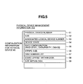
Fig. 5 shows one example of physical device management
information in the first aspect;
Fig. 6 shows one example of external device management
information in the first aspect;
Fig. 7 shows one example of storage management
information in the first aspect;
Fig. 8 shows the flow of processing by an input/output
request processing program in the first aspect;
Fig. 9 shows the flow of processing by an external device
monitoring processing program in the first aspect;
Fig. 10 shows the flow of processing by a storage
monitoring processing program in the first aspect;
Fig. 11 shows the flow of processing by an external
device transfer instruction processing program in the first
aspect;
Fig. 12 shows the flow of processing by an external
device transfer processing program in the first aspect;
Fig. 13 shows the flow of processing by an external
device recovery processing program in a second aspect; and,
Fig. 14 shows one example of logical device management
information in the second aspect.
DESCRIPTION OF THE PREFERRED EMBODIMENTS
As aspects of the invention, first and second aspects are
explained.
The first aspect is summarized below.
The system assumed in the first aspect is a storage
system in which one or more first storage units are connected,
as external storage, to a second storage unit having external
storage connection functions.
Here, the external storage connection functions of the
above second storage unit are functions by which, upon
receiving an access request from the host, the second storage
unit judges whether the device for input/output of the access
request is a device existing in a first storage unit or is a
device in the second storage unit itself, and if a device in a
first storage unit, transmits the access request to the first
storage unit, but if a device in itself, accesses the device.
The first aspect endeavors to provide data integrity, at
the time that a prognostication of occurrence of a fault in a
device within a first storage unit is discovered, by
transferring data stored in the device for which the fault
prognostication has occurred to another device.
A server provided to manage storage (hereafter called a
"management server") detects the occurrence of
prognostications of faults in a first storage unit, based on
anomaly reports from first storage units, and on warnings from
the second storage unit of anomalies in first storage units.
Warnings are issued from the second storage unit based on
prognostications of faults in first storage units, detected by
monitoring responses during accessing of first storage units
and similar.
The management server, after detecting a fault
prognostication, identifies devices within the first storage
unit of the fault prognostication which would be affected were
the fault to occur, and decides on the device for data
transfer, while also selecting the device to be the transfer
target based on the attributes of the device for data transfer.
Then the data transfer is instructed to the first storage unit.
The second aspect is summarized below.
Similarly to the first aspect, a storage system of the
second aspect is configured with one or more first storage
units connected to a second storage unit having external
storage connection functions. In the second aspect, a first
storage unit uses a plurality of devices in a RAID (Redundant
Array of Independent Disks) configuration, which is provided
to the host as a disk device of the second storage unit.
In the second aspect, in addition to a function to
endeavor to provide data integrity prior to occurrence of a
fault similarly to the first aspect, the data stored in a
device in which a fault actually occurs is recovered and is
transferred to another device.
Similarly to the first aspect, upon receiving a first
storage unit anomaly report the management server identifies
the range affected by the anomaly, decides on the transfer
source and transfer target, and issues a data transfer
instruction to the second storage unit. Further, upon
receiving a report of the actual occurrence of a fault, the
management server utilizes RAID properties to recover the data
stored on the device in which the fault occurred, and issues
an instruction to the second storage unit to store the
recovered data on a device selected as the transfer target.
First Aspect
The first aspect is explained referring to Fig. 1 through
Fig. 12.
Fig. 1 shows one example of the hardware configuration of
a computer system to which the first aspect of this invention
is applied.
The computer system comprises one or more host computers
(hereafter called "hosts") 100; a management server 110; a
fibre channel switch 120; storage unit 130; a management
terminal 140; and external storage unit 150a and 150b
(collectively called "external storage 150").
The hosts 100, storage unit 130 and external storage unit
150 are connected to ports 121 of the fibre channel switch 120
via the ports 107, 131, 151 respectively. The host 100,
storage unit 130, external storage unit 150, and fibre channel
switch 120 are connected to the management server 110 via the
interface control portions (I/F) 106, 138, 157, 123
respectively through the IP network 175, and are integrated
and managed by storage management software, not shown, which
runs on the management server 110.
In this aspect, the storage unit 130 is connected to the
management server 110 via the management terminal 140; however,
a configuration may be employed in which the storage unit 130
is connected directly to the IP network 175.
The hosts 100 are computers which execute applications
and access the storage unit 130, and each comprise a CPU 101,
memory 102, storage device 103, input device 104, output
device 105, interface control portion 106, and port 107.
The CPU 101 reads the operating system, application
programs, and other software stored on a hard disk, magneto-optical
disk or other storage device 103 to memory 102, and by
executing the software performs prescribed functions.
The input/output device 104 is a keyboard, mouse or
similar, which receives input from the host manager. The
output device 105 is a display or similar, which outputs
information as instructed by the CPU 101. The interface
control portion 106 is provided for connection to the IP
network 175, and the port 107 is provided for connection to
the fibre channel switch 120.
The management server 110 is a computer which manages
operation and maintenance of the entire computer system of
this aspect, and is a computer comprising a CPU 111, memory
112, storage device 113, input device 114, and output device
115.
The input/output device 114 is a keyboard, mouse or
similar, which receives input from the storage manager. The
output device 115 is a display or similar, which outputs
information as instructed by the CPU 111. The interface
control portion 116 is provided for connection to the IP
network 175.
The CPU 111 reads storage management software and similar,
stored on a hard disk, magneto-optical disk or other storage
device 113, into memory 112, and by executing the software
performs prescribed functions.
The management server 110 collects configuration
information, resource usage rates, performance monitoring
information, fault logs and similar from various equipment
within the computer system via the interface control portion
116 and IP network 175, according to the storage management
software, and outputs the collected information to the output
device 115, to present the information to the storage manager.
The management server 110 transmits operation and
maintenance instructions, received from the storage manager
via the input device 114, to various equipment via the
interface control portion 116.
The storage unit 130 is storage unit comprising external
storage connection functions, and further comprises one or
more ports 131; one or more control processors 132; one or
more memory units 133 connected to the control processors 132;
one or more disk caches 134; one or more control memory units
135; one or more ports 136; one or more disk devices 137
connected to the ports 136; and an interface control portion
138.
The control processor 132 identifies the device to be
accessed for an input/output request received from a host 131,
and processes the input/output request for a device within a
disk device 137 or external storage unit 150 corresponding to
the identified device.
The device to be accessed is identified by a port ID and
LUN (Logical Unit Number), contained within the input/output
request received by a control processor 132.
In this aspect, the ports 131 are assumed to be ports to
the fibre channel interface which use SCSI (Small Computer
System Interface) as the higher-level protocol. However, the
ports may also be ports to IP network interfaces using SCSI as
the higher-level protocol, or ports to other network
interfaces for connection to storage unit.
The device to be accessed is identified from the port ID
and LUN contained in the input/output request as follows.
The storage unit 130 of this aspect has the following
device hierarchy.
A disk array is configured from a plurality of disk
devices 137. The control processors 132 manage the disk array
as a physical device. The control processors 132 also
allocate logical devices to the physical devices within the
storage unit 130 (that is, the control processors 132
associate physical devices with logical devices).
Here, logical devices are associated with LUNs allocated
to each of the ports 131, and are provided to hosts 100 as
devices of the storage unit 130. A logical device is managed
within the storage unit 130, and its number is managed
independently for each storage unit. A host 100 recognizes
only logical devices of the storage unit 130. A host 100 uses
the LUN of a port 131 associated with a logical device to
access data stored in the storage unit 130.
The storage unit 130 of this aspect also has functions to
render virtual the devices in external storage unit 150 as its
own devices. A logical device provided by external storage
unit 150 (hereafter called an "external device") to storage
unit 130 is rendered virtual as a device of the storage unit
130 and provided to the host 100. Within the storage unit 130,
an external device is, like a physical device within the
storage unit 130, associated with and managed as one or more
logical devices of the storage unit 130.
In order to realize the above device hierarchy, a control
processor 132 manages the associative relations between
logical devices, physical devices, disk devices 137, external
devices, and the physical devices of external storage unit 150.
In this aspect, these associative relations are retained in
control memory 135.
A control processor 132 converts access requests for a
logical device into access requests for devices within a disk
device 137 or for logical devices of external storage unit,
based on the associative relations managed by the control
processor 132.
The storage unit 130 of this aspect combines a plurality
of disk devices 137 to define one or a plurality of physical
devices (that is, a plurality of disk devices 137 are combined
and associated as one or a plurality of physical devices),
allocates one logical device to one physical device, and
provides this to a host 100. However, each disk device 137
may instead be provided to a host 100 as one physical device
and as one logical device.
In addition to input/output processing for devices, a
control processor 132 also executes various processing to
realize data links between devices, such as data copying and
data redistribution.
Further, a control processor 132 transmits configuration
information for presentation to the storage manager to a
management terminal 140, connected via the interface control
portion 138; receives maintenance and operation instructions,
input by the manager to the management terminal 140, from the
management terminal 140; and alters the configuration of the
storage unit 130 and similar according to the received
instructions.
The above-described functions of control processors 132
are realized through execution of a program stored in memory
133.
In order to improve the speed of processing of access
requests from a host 100, the disk cache 134 stores data which
is frequently read from the disk devices 137, and also
temporarily stores write data received from a host 100.
When performing write-after using the disk cache 134, in
order to prevent loss of the write data stored in the disk
cache 134 before writing to the disk device 137, it is
desirable that the disk cache 134 be made nonvolatile memory
through battery backup or other means, or that a duplicate
configuration be employed to improve tolerance with respect to
media faults, or that other means be used to improve the
availability of the disk cache 134.
"Write-after" is processing in which, after write data
received from a host 100 is stored in the disk cache 134, and
before actually writing the data to the disk device 137, a
response to the write request is returned to the host 100.
The control memory 135 stores associative relations
between devices realized in the above-described device
hierarchy and attributes of each device, as well as control
information to manage these devices, and control information
in the disk cache 134 to manage data which either does or does
not reflect disk data. If control information stored in the
control memory 135 disappears, data stored in a disk device
137 cannot be accessed by a host 100, and so it is desirable
that the control memory 135 be made nonvolatile memory through
battery backup or other means, or that a duplicate
configuration be employed to improve tolerance with respect to
media faults, or that a configuration be used to improve
availability.
Each of the components in the storage unit 130 is
connected by internal connections as shown in Fig. 1. Through
these internal connections, data, control information, and
configuration information are transmitted and received between
these components, and the control processors 132 can share and
manage configuration information for the storage unit 130.
From the standpoint of improved availability, it is desirable
that the internal connections be made multiply redundant.
The management terminal 140 comprises a CPU 142; memory
143; storage device 144; interface control portion 141
connected to storage unit 130; interface control portion 147
connected to the IP network 175; input device 145 which
receives input from the storage manager; and output device 146,
such as a display or similar, which outputs to the storage
manager configuration information for storage unit 130 and
management information.
The CPU 142, by reading a storage management program
stored in the storage device 144 to memory 143 and executing
the program, references configuration information, issues
instructions to alter configurations, and issues instructions
to execute specific functions.
The management terminal 140 serves as an interface,
relating to maintenance and operation of the storage unit 130,
between the storage manager or management server 110 and
storage unit 130. The management terminal 140 may be omitted,
the storage unit 130 connected directly to the management
server 110, and the storage unit 130 managed using management
software which runs on the management server 110.
Next, the software configuration of the storage unit 130
and management server 110 of this aspect is explained.
Fig. 2A is a software configuration diagram showing one
example of control information stored in the control memory
135 and memory 133 of the storage unit 130, and of a program
for storage control processing.
The control memory 135 stores logical device management
information 201, physical device management information 202,
external device management information 203, LU path management
information 204, and cache management information 205. In
this aspect, this control information is stored in control
memory 135 in order to prevent information loss.
The control information stored in control memory 135 can
be referenced and altered by a control processor 132. However,
a control processor 132 accesses control memory 135 via
internal connections. In this aspect, in order to improve
processing performance, a copy of the control information
necessary for processing executed by each control processor
132 is retained in memory 133 as a copy 211 of device
management information. The information retained as the copy
211 of device management information is the logical device
management information 201, physical device management
information 202, external device management information 203,
and LU path management information 204.
In addition to the copy 211 of device management
information, the memory 133 also stores an input/output
request processing program 221, an external device monitoring
processing program 222, and an external device transfer
processing program 223.
Device management information for the storage unit 130 is
also transmitted to the control terminal 140 and management
server 110, where it is stored.
When the configuration of the storage unit 130 is altered
by the management server 110 or management terminal 140 in
conformance with storage management software, or upon
receiving an instruction from the storage manager, or when the
configuration of the storage unit 130 changes due to a fault,
automatic substitution or similar, one of the control
processors 132 updates the relevant device management
information in the control memory 135.
And, the control processor 132 which has updated the
device management information then notifies the other control
processor 132, the management terminal 140, and the management
server 110 of the fact that the relevant device management
information has been updated.
Fig. 2B is a software configuration diagram showing one
example of control information stored in the memory 112 of the
management server 110, as well as a program for storage
control processing.
The memory 112 stores a copy 231 of device management
information collected from the storage unit 130 and external
storage unit 150, as well as storage management information
232 indicating the attributes of the storage unit 130 and
external storage unit 150. In order to avoid data loss, this
information may also be retained in the storage device 113
installed in the management server 110.
In addition, the memory 112 also stores a storage
monitoring processing program 241 and an external device
transfer instruction processing program 242.
Below, this control information is explained.
Fig. 3 shows one example of logical device management
information 201.
Configuration information for each of the logical devices
is stored in the logical device management information 201.
In this aspect, an information set comprising the logical
device number 31, size 32, associated physical/external device
number 33, device state 34, port number/target ID/LUN 35,
connected host name 36, physical/external device number during
transfer 37, data transfer progress pointer 38, and data
transfer execution flag 39, is stored for each logical device
in the logical device management information 201.
A number uniquely allocated to each logical device by a
control processor 132 to identify the logical device is stored
as the logical device number 31.
The capacity of the logical device specified by the
logical device number 31 is stored as the size 32.
The number of the physical device or external device
associated with the logical device is stored as the associated
physical/external device number 33. In this aspect, the
physical device number 51 or external device number 61, which
is stored in the physical device management information 202 or
external device management information 203 which are
management information for the device, is stored as the
associated physical/external device number 33. Details of
this are explained below.
In this aspect, logical devices and physical/external
devices are associated in a one-to-one correspondence.
Consequently only one number of an associated physical device
or external device is stored as the associated
physical/external device number 33. When a plurality of
physical/logical devices are combined to form a single logical
device, an area becomes necessary in the logical device
management information 201 for storing a list of numbers of
physical/external devices associated with each logical device,
and the number of such numbers. Also, when a logical device
is undefined, an invalid value is set as the associated
physical/external device number 33.
Information indicating the state of the logical device is
set in the device state 34. States which may be set include
"online", "offline", "uninstalled", and "fault-offline".
"Online" indicates that the logical device is operating
normally and is in a state enabling access by a host 100.
"Offline" indicates that the logical device is defined and is
operating normally, but because the LU path is undefined or
for some other reason, is not in a state enabling access by a
host 100. "Uninstalled" indicates that the logical device is
not defined, and so is not in a state enabling access by a
host 100. "Fault-offline" indicates that a fault has occurred
in the logical device, and that access by a host 100 is not
possible.
The initial value of the device state 34 is
"uninstalled"; when the logical device is defined, this is
changed to "offline", and when the LU path is defined, this is
again changed to "online".
The port number, target ID, and LUN are stored in the
port number/target ID/LUN 35.
A port number stored in the entry 35 is information to
identify a port 131 of a logical device for which a LUN is
defined. The port identification information is a number,
assigned to each port 131, which is determined uniquely within
the storage unit 130. Information indicating to which port
among the plurality of ports 131 the logical device is
connected, that is, the number of the port 131 used to access
the logical device, is set in the entry 35.
The target ID and LUN stored in the entry 35 are
identifiers used to identify the logical device. In this
aspect, as identifiers used to identify a logical device, a
SCSI-ID used for accessing by a host 100 via SCSI, and the LUN,
are stored.
The above-described values are set in the entry 35 when a
LU path definition is executed for a logical device.
The connection host name 36 is a host name which
identifies the host 100 which is permitted to access the
logical device. As the host name, a WWN (World Wide Name)
assigned to the port 107 of the host 100, or any other value
capable of uniquely identifying the host 100 or the port 107,
may be used. The entry 36 is set by the storage manager at
the time the logical device is defined.
As the physical/external device number during transfer 37,
the physical/external device number of the transfer target of
the physical/external device to which the logical device is
allocated during data transfer (when the data transfer
execution flag 39, described below, is "on"), is stored.
The data transfer progress pointer 38 is information
indicating the leading address of the area for which data
transfer processing has not been completed, and is updated as
the data transfer progresses.
The initial value of the data transfer execution flag 39
is "off", and when set to "on" indicates that data transfer is
in progress, from the physical/external device to which the
logical device is allocated to another physical/external
device. The physical/external device number during transfer
37 and data transfer progress pointer 38 are valid only when
the data transfer execution flag 39 is set to "on".
Fig. 4 shows an example of LU path management information
204. For each of the ports 131 in the storage unit 130, the
LU path management information 204 stores information for a
valid LUN defined for each port.
A LUN defined for (allocated to) a port 131 is stored in
the target ID/LUN 41. The number of the logical device to
which the LUN is allocated is stored as the associated logical
device number 42. Information indicating the host 100 allowed
access to the LUN defined for the port 131 is stored as the
connected host name 43. The WWN assigned to the port 107 of
the host 100 is for example used as the information indicating
the host 100.
In some cases the LUNs of a plurality of ports 131 are
defined for (allocated to) a single logical device, so that
the logical device can be accessed from a plurality of ports
131. In such cases, the union of the connected host names 43
of LU path management information 204 for all of the LUNs of
the plurality of ports 131 is stored as the connected host
name 36 of the logical device management information 201 for
the logical device.
Fig. 5 shows one example of physical device management
information 202 used for management of physical devices
comprised by disk devices 137.
Each storage unit 130 retains for each physical device
existing within its equipment, as the physical device
management information 202, an information set comprising the
physical device number 51, size 52, associated logical device
number 53, device state 54, RAID configuration (RAID level,
data/parity disks) 55, stripe size 56, disk number list 57,
start offset within disk 58, and size within disk 59.
An identification number to identify the physical device
is registered as the physical device number 51. The capacity
of the physical device specified by the physical device number
51 is stored as the size 52. The logical device number
associated with the physical device is stored as the
associated logical device number 53. The associated logical
device number 53 is stored at the time the logical device is
defined. When the physical device is not allocated to a
logical device, an invalid value is set as the associated
logical device number 53.
Information indicating the state of the physical device
is set in the device state 54. States which may be set
include "online", "offline", "uninstalled", and "fault-offline".
"Online" indicates that the physical device is
operating normally and is in a state of allocation to a
logical device. "Offline" indicates that the physical device
is defined and is operating normally, but is in a state of not
being allocated to a logical device. "Uninstalled" indicates
that the physical device is not defined for the disk device
137. "Fault-offline" indicates that a fault has occurred in
the physical device, and that the physical device is not
allocated to a logical device.
In this aspect, for simplicity it is assumed that
physical devices are already created in disk devices 137 at
the time of factory shipment. Hence the initial value of
device states 53 for physical devices which can be used is
"offline", and for other devices is "uninstalled". At the
time that a logical device is defined for a physical device,
the state is changed to "online".
Information relating to the RAID level, the number of
data disks and parity disks, and other RAID configuration
information for the disk device 137 to which a physical disk
is allocated is stored in the RAID configuration 55. The data
division unit (stripe) length in the RAID system is stored as
the stripe size 56. Identification numbers for each of the
plurality of disk devices 137 comprised by the RAID system to
which the physical device is allocated are stored as the disk
number list 57. The identification numbers for disk devices
137 are assigned values which are used to uniquely identify
each disk device 137 in the storage unit 130.
The start offset within disk 58 and size within disk 59
store information indicating to which areas within the disk
devices 137 a physical device is allocated. In this aspect,
for simplicity, it is assumed that, for all physical devices,
the offset and size are unified within each disk device 137
comprised by the RAID system.
Fig. 6 shows one example of external device management
information 203 used to manage external devices provided to
the storage unit 130 by external storage unit 150 connected to
the storage unit 130.
For each external device, the storage unit 130 stores, as
external device management information 203, an external device
number 61, size 62, associated logical device number 63,
device state 64, storage identification information 65,
external storage device number 66, initiator port number list
67, and target port ID/target ID/LUN list 68.
A value allocated uniquely within the storage unit 130 to
the external device by a control processor 132 is stored as
the external device number 61. The capacity of the external
device specified by the external device number 61 is stored as
the size 62. The number of the logical device within the
storage unit 130 with which the external device is associated
is registered as the associated logical device number 63.
Information indicating the state of the external device
is set as the device state 64. The states which can be set
and their meanings are the same as the device states 54 of the
physical device management information 202. Because the
storage unit 130 is not connected to the external storage unit
150 in the initial state, the initial value of the device
state 64 is "uninstalled".
Information to identify the external storage unit 150 in
which the external device is installed is saved as the storage
identification information 65. As identification information,
a value may be used which uniquely identifies the external
storage unit 150. For example, a combination of vendor
identification information and of a serial number assigned
uniquely by each vendor to the storage unit 150 may be used.
An identification number assigned to the external device
by the external storage unit 150 in which the external device
is installed is stored as the external storage device number
66. In this aspect, an external device is a logical device of
external storage unit 150, and so the logical device number
assigned for use in identifying the logical device which the
external storage unit 150 itself has defined is stored as the
external storage device number 66.
The identification number for a port 131 of storage unit
130 capable of accessing the external device is registered as
the initiator port number list 67. When the external device
can be accessed from a plurality of ports 131, all the
identification numbers of ports capable of access are
registered.
When the external device defines LUNs for one or more
ports of the external storage unit 150, one or a plurality of
port IDs for these ports 151, and the target IDs/LUNs
allocated to the external device, are stored as the target
port ID/target ID/LUN list 68. When a control processor 132
of the storage unit 130 accesses an external device (when an
input/output request is transmitted by the control processor
from a port 131 to an external device), the target ID and LUN
allocated to the external device by the external storage unit
150 to which the external device belongs are used as
information to identify the external device.
In this aspect, the storage unit 130 uses the above-described
four items of device management information (logical
device management information 201, physical device management
information 202, external device management information 203,
and LU path management information 204) to manage the device.
It is assumed that at the time of factory shipment of the
storage unit 130, physical devices are defined for each of the
disk devices 137. Further, at the time of introduction of the
storage unit 130 a user or storage manager defines logical
devices of external storage unit 150 connected to the storage
unit 130 as external devices, defines logical devices for the
physical devices and external devices, and defines LUNs for
each port 131 for the defined logical devices.
Fig. 7 shows an example of storage management information
232 in the management server 110.
Information used to manage the storage unit 130 and
external storage unit 150 managed by the management server 110
is stored in the storage management information 232. In the
following explanation of the storage management information
232, when there is no need in particular to distinguish the
storage unit 130 and external storage unit 150, both are
represented as "storage unit". Similarly, disk devices 137,
156 and control processors 132, 152 which are components of
storage unit are represented as "disk devices" and "control
processors".
An information set comprising, for each storage unit, a
storage number 71, storage name 72, port name list 73,
performance/reliability level 74, total capacity 75, and free
capacity 76, is stored as the storage management information
232.
A number determined uniquely within the system and
allocated to each storage unit by the management server 110 is
stored as the storage number 71.
Information indicating an identifier used to specify the
storage unit is registered as the storage name 72. As the
identifier, the platform WWN of the fibre channel, or a
combination of the vendor identifier and product number for
the storage unit, may be used.
WWNs assigned to ports of the storage unit are stored in
the port name list 73. A host 100 uses the port WWNs of the
storage unit 130 stored in the port name list 73 to specify a
port to be used when accessing a device in the storage unit
130.
Values representing evaluations, based on unified
standards for computer systems, of the performance and
reliability of the storage unit, are stored in the
performance/reliability level 74.
Indexes used to evaluate performance may include such
performance values as the seek time and disk rotation speed of
the disk devices installed in the storage unit, the storage
capacities of disk devices, the RAID level configuration in
the storage unit, the communication bandwidth of connections
between control processors and disk devices, port
communication bandwidths, the number of communication lines,
the storage capacity of the disk cache, and nominal
performance values for the storage unit overall.
Depending on the storage unit, there are cases in which
disk devices with different attributes and RAID configurations
with different attributes coexist within the equipment, so
that there are a plurality of performance levels within a
single storage unit. But in this aspect, for simplicity, it
is assumed that the performance level is set for each storage
unit, and can be managed for each storage unit.
Indexes used to evaluate reliability may include the
redundancy of the disk devices, control processors, or other
components of the storage unit, the RAID level used by the
storage unit, the number of substitution paths which can be
used, and various other conditions related to product
specifications. The various functions of the storage unit,
such as for example functions provided by the storage unit for
copying or saving logical devices, can also be used as indexes
in evaluating reliability.
With respect to the reliability level also, depending on
the storage unit it is possible for storage areas with
different reliability levels to coexist internally; but to
simplify the explanation, in this aspect it is assumed that
each storage unit has a single reliability level, and that
each storage unit can be managed individually.
In this aspect, performance and reliability levels are
managed using five stages of values, from a maximum of "5" to
a minimum of "1". The value of the level for each storage
unit is determined and set by the storage manager based on
catalog values for the storage unit and on the results of
tests at the time of equipment introduction.
Information indicating the total capacity of storage
areas which can be used in the storage unit is registered as
the total capacity 75. The total capacity of storage area
which can be used is determined by the storage capacities of
disk devices in the storage unit, and by the RAID level
configuration in the storage unit. In this aspect, it is
assumed that physical devices which can be used are set in
advance, and that the total capacity of physical devices which
can be used is registered as the total capacity 75.
Information indicating the total capacity of physical
devices for which a logical device is not yet defined, among
all the physical devices in the storage unit, is registered as
the free capacity 76. In this aspect, information indicating
the total storage capacity of physical devices in the
"offline" state is registered as the free capacity 76.
Because physical devices in the "uninstalled" state cannot be
used by a host 100, the capacity of such devices is not
included.
In the case of an aspect in which a physical device
required by the management server 110 is defined according to
instructions from a user or storage manager, information
indicating the total capacity of unused areas in disk devices
installed in the storage unit is registered as the free
capacity 76.
Next, returning to Fig. 2, programs stored in the memory
133 and 112 of the storage unit 130 and management server 110
are explained. These programs are executed by each of the
control processors and CPUs.
The input/output request processing program 221, external
device monitoring processing program 222, and external device
transfer processing program 223, which are stored in memory
133 of the storage unit 130, as well as the storage monitoring
processing program 241 and external device transfer
instruction processing program 242, which are stored in memory
112 of the management server 110, are explained.
The input/output request processing program 221 realizes
input/output processing for a logical device. Upon detecting
an external device anomaly (a phenomenon which is a
prognostication of the occurrence of a fault in an external
device) during input/output processing, the input/output
request processing program 221 notifies the management server
110.
The external device monitoring processing program 222
periodically monitors external devices, and upon detecting an
anomaly in an external device, notifies the management server
110.
The external device transfer processing program 223
performs processing to transfer the data of a specified
external device to another device, according to an instruction
from the management server 110.
The storage monitoring processing program 241 receives
warnings of anomalies in external devices and fault reports
from the storage unit 130 and external storage unit 150,
creates transfer plans for external devices according to
received reports and similar, and issues instructions for
transfer of external device data to the storage unit 130.
The external device transfer instruction processing
program 242 determines the transfer target when an external
device for transfer is specified by the storage monitoring
processing program 241.
These programs are used in storage control processing
within the various components as explained below.
Data transfer instructions issued when an external device
anomaly is detected are executed in concert by the
input/output request processing program 221 and/or external
device monitoring processing program 222 of the storage unit
130, and by the storage monitoring processing program 241 of
the management server 110.
Processing to detect anomalies in external devices during
input/output request processing, which is performed by the
input/output request processing program 221, is explained
below.
Fig. 8 shows an example of the flow of processing to
detect anomalies in external devices during input/output
request processing, performed by the input/output request
processing program 221.
A control processor 132 identifies the physical device or
external device associated with the logical device of an
input/output request received, from a host 100 at each port
131, for a logical device of the storage unit 130, and
performs input/output processing for the physical device, or
transmits an input/output request to the external storage unit
150 of the external device, according to the input/output
request processing program 221.
In this aspect, upon receiving a fibre channel command
frame (step 801), the control processor 132 references the LU
path management information 204 and logical device management
information 201, and acquires the logical device number which
the frame is to access from the LUN contained in the received
frame, as well as the physical device number or external
device number associated with the logical device (step 802).
When the acquired logical device is associated with a
physical device in the storage unit 130, the control processor
132 performs data input/output processing for the disk device
137 housing the physical device, using the disk cache 134, to
complete the input/output request processing (step 803).
When on the other hand the logical device is an external
device, the control processor 132 performs input/output
processing for the external device via a port 131 (step 804).
An input/output request for an external device entails
essentially the same processing as an input/output request
issued by a host 100 for a logical device presented by the
storage unit 130.
If, during input/output processing for an external device,
an access fault, decline in performance, or other external
device anomaly is detected (step 805), the control processor
132 warns the management server 110 of the detection of an
external device anomaly (step 806). The warning should
include information enabling identification of the fact that
an access fault or performance fault has occurred. A warning
may also include information to identify the external device
for input/output processing, information indicating the
grounds for judging an anomaly to have occurred, and similar.
If an external device anomaly is not detected, normal
input/output processing is performed.
Detection of access faults or performance decreases in
this aspect is performed as follows.
Access faults are judged and detected through responses
to input/output requests which have been sent.
External device access faults occur when, for example, a
fault (due to cutting or removal of a cable, a switch fault,
or similar) occurs in the network leading from ports 131 of
the storage unit 130 to ports 151 of the external storage unit
150, or when a fault occurs in a port 151 of the external
storage unit 150, in a control processor 152, or similar.
Such access faults are detected through time-outs, as
seen by the control processor 132, of input/output requests
transmitted to an external device, because access through the
specified port 151 is not possible. Having detected the timeout
of an input/output request, a control processor 132
executes substitution path processing, similarly to normal
cases for disk devices within the storage unit.
First, when an input/output request using a specified
port 151 times out, the control processor 132 confirms the
state of the path to the external storage unit 150 using the
port in question 151.
If the path state is normal, a specified number of
input/output requests are again sent over the same path, and
if not all of these are successful, the port is switched to a
substitute port, and input/output requests are sent once again.
If the path state is not normal, repeated trials of the path
are skipped, and switching to a substitute port is performed
first before resending input/output requests.
If input/output requests from the substitute port are
processed without incident, the control processor 132
transmits to the management server 110 a warning message
indicating the fact of occurrence of an access fault in the
external device.
When, as a result of the above processing, notification
of a change in the network state is received, if as a result
of checks of the links for all ports 151 of external storage
unit 150 for which links have been established (in a fibre
channel, node port login) it is found that a link is broken,
or when in input/output processing for an external device
time-outs have occurred more than a specified number of times
for a path using a specified port 151, then the path state is
changed to a "blocked" state.
In this aspect, when input/output requests fail for all
substitute ports, input to and output from the relevant
external device is not possible, and data is lost.
Performance decreases are detected through decreases in
responsiveness and throughput of input/output requests for an
external device. Each time an input/output request is sent,
the control processor 132 acquires the response time and
throughput information for the request. The average response
times and throughput values acquired in advance are compared
for each external storage unit 150, and when the divergence
between values is large, an anomaly is judged to have occurred.
The divergence threshold value for judgment of occurrence of
an anomaly is stored in for example the memory 133 of the
storage unit 130, together with information on average
response times and throughput.
When, because there is divergence in responsiveness and
throughput, it is judged that an anomaly has occurred,
information indicating the grounds for this judgment (the
responsiveness or throughput) is included in the warning.
Degradation of responsiveness or throughput may occur,
for example, as a result of such anomalies as single-sided
blockage of the disk cache 154. In normal write processing, a
completion response is sent when duplicate writing to the disk
cache 154 of the external storage unit 150 is completed. But
when there is blockage of one of the disk caches 154 to which
duplicate writing of data is performed, write-through occurs
in which the completion response is sent only when direct
writing to the disk device 156 is completed. In write-through
mode, the write performance drops dramatically, and problems
such as degradation of responsiveness and throughput occur.
The detection of an access fault or performance decline
signifies a decline in the redundancy of the network,
processor, or similar which guarantees access to the external
device. Hence in order to guarantee access to data stored in
the external device, either redundancy must be restored
quickly, or the data of the external device must be saved to
(transferred to) another device.
A control processor 132 which has detected an anomaly
transmits a message or signal to the management server 110
warning of an anomaly in the external device, and causes the
management server 110 to acknowledge the occurrence of the
anomaly.
Next, processing to detect anomalies in external devices
by the external device monitoring processing program 222 is
explained. A control processor 132 periodically monitors the
operating state of external devices according to the external
device monitoring processing program 222.
The occurrence of faults during input/output processing
in an external device which is accessed by a host 100 with a
certain frequency can be detected according to the
input/output request processing program 221. However, in the
case of external devices storing archive data, or in the cases
of other devices accessing of which occurs only rarely, it is
necessary to monitor the state of the external device on
occasions other than accessing by a host 100. Consequently
external device monitoring processing is provided, according
to the external device monitoring processing program 222.
Fig. 9 is one example of the flow of processing to detect
anomalies in an external device by the external device
monitoring processing program 222.
The control processor 132 periodically starts the
external device monitoring processing program 222 with a
predetermined frequency. The startup frequency is set so as
not to impede input/output requests from hosts 100.
The control processor 132 selects the external device for
which to perform trial input/output from among all the
external devices being managed and described in the external
device management information 203 (step 901), and executes
test I/O (for example, read processing) for the external
device thus selected (step 902), according to the external
device monitoring processing program 222.
In this step, the external device for testing is selected
each time based on the time elapsed from the last time the
device was accessed by a host 100, and other criteria. The
method of selection is not limited to this method. Further,
in this aspect trial input/output is performed for one
external device upon each startup; but trial input/output may
be performed for a plurality of external devices.
In the trial input/output for the selected external
device, when an anomaly is detected in the external device
(step 903), the control processor 132 warns the management
server 110 of the external device anomaly (step 904). The
method of anomaly detection is the same as in step 805 of the
flow of input/output request processing, and so an explanation
is omitted.
In this way, when the control processor 132 detects an
anomaly which may impede access to an external device being
managed, it warns the management server 110 of this fact. In
the management server 110, transfer processing of the external
device is performed, based on the external device anomaly
warning from the storage unit 130, which is virtualized
storage, and/or on a fault occurrence report from storage unit
being managed (the external storage unit 150 which is virtual
storage).
Below is an explanation of the processing performed by
the management server 110 upon receiving a warning from the
storage unit 130 indicating the occurrence of an anomaly in an
external device (hereafter called "anomaly warnings"), and/or
a fault occurrence report from storage unit being managed
(external storage unit 150).
Fig. 10 is one example of the flow of processing of the
storage monitoring processing program 241 executed by the
management server 110. The CPU 111 performs the following
processing by executing the storage monitoring processing
program 241.
The CPU 111 receives an anomaly warning from the storage
unit 130, and/or a fault occurrence report from the external
storage unit 150 (step 1001).
The CPU 111 analyzes the received anomaly warning and/or
fault report (step 1002).
The CPU 111 decides which external devices are affected,
according to information stores in the received anomaly
warning and/or fault report, and also judges whether data
transfer is necessary for logical devices judged to be
affected, and selects the range of external devices (logical
device group) for transfer (step 1003).
Here, upon receiving an anomaly warning, the CPU 111
extracts information for the external device stored in the
anomaly warning as well as the anomaly details (access fault,
decline in responsiveness or throughput). Based on the
extracted external device information and anomaly details, the
external storage unit 150 comprising the external device is
accessed, and existing techniques are used to investigate the
details of the location of fault occurrence, the extent of the
fault, and similar.
When a fault report is received, the information stored
in the fault report is used to identify the location of fault
occurrence, extent of the fault, and similar.
The location of fault occurrence is for example the site
of the fan, power supply, disk cache, port, disk device, or
similar of the external storage unit 150 for which a fault has
been reported; the extent of the fault is a level indicating
whether, due to the fault occurrence, the site cannot be used,
or whether the fault is temporary and recovery to normal is
already in progress with respect to configuration information
of the storage unit; the extent of the fault can be judged
from information on the type of fault. In the latter case,
recovery to the normal state is in progress, and so no action
need be taken with respect to the external device in question.
The CPU 111 receives the latest configuration information,
including device information, from the external storage unit
150 for which an anomaly warning and/or fault report was
issued, and identifies the logical device group for which
availability is reduced as a consequence of the fault.
For example, when the site of the fault occurrence is the
fan and power supply, and if there are few remaining
replacements for the fan and power supply, the availability of
all logical devices mounted in the storage unit is reduced.
In this case, the CPU 111 determines that the range of reduced
availability is the entirety of logical devices.
When a fault occurs in one side of the doubly redundant
memory of the disk cache 154 due to a fault, it is anticipated
that there will be a sharp decline in the availability and
performance level of all the logical devices of the external
storage unit 150 for which the anomaly warning and/or fault
report is issued. In this case also, the CPU 111 determines
that the range over which availability is degraded extends to
all the logical devices of the external storage unit 150.
When a fault occurs in a specific disk device 156, and
the redundancy of the RAID group to which the disk device 156
belongs is lost, and if there remain no substitute disk
devices within the external storage unit 150 comprising the
disk device 156, then the availability of the logical disk
group associated with the RAID group is reduced. In this case,
the CPU 111 determines that the range over which availability
is degraded is the logical device group associated with the
RAID group to which the disk device 156 in which the fault has
occurred belongs.
When the logical device group which is affected has been
determined, the CPU 111 uses the external device management
information within the copy 231 of the device management
information to investigate whether, in the logical device
group affected by the reported fault, there exist any devices
which are managed as the external devices of other storage
unit.
When the external device group for transfer is determined,
the CPU 111 issues an instruction for transfer of the data
within the external device for transfer to the storage unit
130, according to the external device transfer instruction
processing program 242 (step 1004).
When external device transfer (data transfer) by the
storage unit 130 is completed, and a transfer completed
notification is received from the storage unit 130, the CPU
111 receives into memory 112 the updated device configuration
information for the storage unit 130 (logical device
management information 201, physical device management
information 202, external device management information 203,
LU path management information 204) as a copy 231 of the
device management information, and processing is concluded
(step 1005).
Next, details of the processing of the above step 1004,
performed according to the external device transfer
instruction processing program 242, are explained.
Fig. 11 is one example of the flow of processing by the
CPU 111 of the management server 110, according to the
external device transfer instruction processing program 242.
When external devices for which device transfer is
necessary are determined according to the storage monitoring
processing program 241, the CPU 111 takes these external
devices to be the transfer source, determines the transfer
target device, and issues an external device transfer
instruction (instruction to perform data transfer) to the
storage unit 130.
First, the CPU 111 references the storage management
information 232 and similar, to confirm the performance,
reliability level, and other attributes of the transfer source
devices (step 1101).
The CPU 111 investigates whether there exists an unused
physical device in the external storage unit 150a, 150b under
management by the storage unit 130 which has virtualized and
managed the external devices which are the transfer source
devices or in the storage unit 130, that is, a (free) device
not allocated to a logical device and having a
performance/reliability level and similar equal to or
exceeding that of the transfer source devices (step 1102).
The copy 231 of device management information for each of
the storage units and the storage management information 232
in the memory 112 of the management server 110 are used in
this investigation of free devices.
When there exists a free device under the management of
the storage unit 130, which is unused and satisfies the above
conditions, the CPU 111 determines this device to be the data
transfer target (step 1105). When the transfer target is
determined, the CPU 111 transmits an external device transfer
instruction to the storage unit 130 (step 1106). Information
specifying the transfer source and transfer target is
contained in the external device transfer instruction. In
this aspect, the external device number 61 of the external
devices is used. In cases in which the transfer target is a
device of the storage unit 130, the physical device number 51
is used instead of an external device number 61.
When on the other hand no free device exists, the CPU 111
investigates whether there exists a free device satisfying the
conditions within storage unit which is under the management
of the management server 110, and which is not under the
virtualized control of the storage unit 130 (step 1103).
If a free device satisfying the conditions is found, the
CPU 111 instructs the storage unit 130 to register the device
as an external device (step 1104).
The processing performed in step 1104 is similar to the
processing, performed at the time of system construction, in
which the logical devices of other external storage unit 150
connected to the storage unit 130 are registered as external
devices.
Specifically, the control processor 132 issues an inquiry
to the external storage unit 150 in question, and registers
the external device management information 203. Then, in the
management server 110, the logical devices of the external
storage unit in question are associated as external devices of
the storage unit 130, and the copy 231 of the device
management information is updated.
The CPU 111 selects an external device registered in step
1104 as the transfer target (step 1105), and issues an
external device transfer instruction to the storage unit 130
(step 1106).
On the other hand, when in the investigation of step 1103
a free device satisfying the conditions is not found, an
investigation of the existence of devices is performed once
again within the range of investigation of step 1102, that is,
free devices under the virtualized control of the storage unit
130 which, though not satisfying the performance/reliability
level condition, have the capacity of the transfer source
devices (step 1107). This is done in order to avoid storing
data in a device in which a fault has been discovered.
When a free device which satisfies only the capacity
condition is discovered, the CPU 111 selects this device as
the transfer target (step 1105), and issues an external device
transfer instruction to the storage unit 130 (step 1106).
When a free device is not found, an investigation of the
existence of devices is performed once again within the range
of investigation of the next step 1103, that is, free devices
under the management of the management server 110 and not
under the virtualized control of the storage unit 130 which,
though not satisfying the performance/reliability level
condition, satisfy the capacity condition (step 1108).
When a free device is discovered, the CPU 111 instructs
the storage unit 130 to register the free device as an
external device (step 1104), selects the device as the
transfer target (step 1105), and issues an external device
transfer instruction to the storage unit 130 (step 1106).
When a free device cannot be found in step 1108 either,
an output device 115 or similar means are used to inform the
storage manager of the fact that transfer of the transfer
source external device is not possible, and processing is
interrupted (step 1109).
Next, processing of the storage unit 130 upon receiving
an external device transfer instruction from the management
server 110 is explained.
Fig. 12 shows one example of the flow of external device
transfer processing, executed by a control processor 132
according to the external device transfer processing program
223.
External device transfer processing is processing to
transfer the data of a transfer source external device
specified by the management server 110 to a transfer target
device (an external device, or a physical device of the
storage unit 130).
Upon receiving an external device transfer instruction
from the management server 110, the control processor 132
registers the device transfer state in the logical device
management information 201 for the logical device associated
with the transfer source external device (step 1201).
Here, the control processor 132 sets the external device
number 61 or physical device number 51 which is the transfer
target in the physical/external device number during transfer
37, initializes the data transfer progress pointer 38 to 0,
and sets the data transfer execution flag 39 to "On".
The control processor 132 then executes sequential data
transfer from the transfer source external device to the
transfer target physical/external device, from the beginning
to the end, according to the external device transfer
processing program 223, and in accordance with the data
transfer progress pointer 38 (step 1202).
In this aspect, the control processor 132 executes this
external device transfer processing while receiving
input/output from hosts 100. When during data transfer there
is an input/output request from a host 100 for a logical
device associated with an external device which is the
transfer source, the control processor 132 uses the data
transfer progress pointer 38 of the logical device management
information 201 to judge whether transfer of the data to be
accessed has been completed. In the case of input/output for
areas the transfer processing of which is judged not to have
been completed, duplicate writing to both the areas of the
transfer source and transfer target devices, and similar
control is executed.
When data transfer up to the end of the transfer source
external device is completed, the control processor 132
updates the logical device management information 201,
external device management information 203, and physical
device management information 202 for the logical devices,
physical devices, and external devices involved in the data
transfer (step 1203).
That is, the associative relation between logical devices
and external devices or physical devices after the completion
of data transfer is stored in these types of management
information.
Here, the external/physical device number of the transfer
target is set in the associated physical/external device
number 33 of the logical device management information 201,
and the data transfer execution flag 39 is set to "Off".
When the transfer target is a physical device, the number
of the logical device set as the transfer target
external/physical device number in the associated
physical/external device number 33 is set in the associated
logical device number 53 of the physical device management
information 202, and the device state 54 is set to "online".
When the transfer target is an external device, the
number of the logical device set as the transfer target
external/physical device number in the associated
physical/external device number 33 is set in the associated
logical device number 63 of the external device management
information 203, and the device state 64 is set to "online".
Further, an invalid value is set as the associated
logical device number 63 of the external device management
information 203 for the transfer source external device, and
the device state 64 is set to "offline".
When updating of the different types of management
information is completed, the control processor 132 notifies
the management server of the fact that external device
transfer processing has been completed (step 1204).
As explained above, in this aspect appropriate control
can be executed in storage having external storage connection
functions, enabling the detection of anomalies which are
prognostications of faults occurring in external storage
devices, the identification of the range of equipment affected,
and the execution of data transfer.
Hence in this aspect, even when, in a computer system
having a storage system comprising storage unit having
external storage connection functions and external storage
unit connected to the above storage unit, the external storage
unit is a storage device with comparatively low reliability,
the availability of the system as a whole can be improved.
When new storage unit is introduced and the overall
capacity of the storage system is increased, and all the data
held by devices in existing storage is transferred to the new
storage unit to replace the above, it is necessary that the
newly introduced storage unit comprise capacity equal to that
of the existing storage devices, and so the cost of storage
unit introduction is increased. Further, if existing storage
unit and new storage unit are both connected directly to hosts,
control on the host side becomes complicated.
By means of this aspect, new storage unit can be
introduced without modifying the mode of access by hosts, and
a computer system can be constructed in which existing storage
unit can be effectively utilized. As a result, the cost of
equipment introduction can be reduced.
Second Aspect
Next, a second aspect is explained. Here, only
differences with the first aspect are explained.
The hardware configuration of a computer system to which
this aspect is applied is similar to that of the first aspect,
shown in Fig. 1. In this aspect, a plurality of loigcal
devices of the one or more external storage units 150 shown in
the figure are collected to constitute a RAID group. In this
aspect, logical devices are defined for this RAID group. For
simplicity, a one-to-one correspondence between logical
devices and RAID groups is assumed.
By forming RAID groups from the logical devices of the
external storage unit 150, in this aspect two types of methods
to protect the data of external devices are possible; these
are the data transfer method explained in the first aspect,
and a data recovery method using another device comprised by
the RAID group after an external device can no longer be
accessed.
In this aspect, because RAID groups are configured from
logical devices of external storage unit 150, the data stored
as logical device management data 201 differs from that in the
first aspect.
Fig. 14 shows an example of the configuration of logical
device management information 201.
The logical device management information 201 in this
aspect comprises, for each logical device, a logical device
number 1401; size 1402; associated physical/external device
number 1403; device state 1404; RAID configuration (RAID level,
data/parity disks) 1405; stripe size 1406; physical/external
device number list 1407; transfer/recovery source
physical/logical device number and transfer/recovery target
physical/logical device number 1408; data transfer/recovery
progress pointer 1409; and data transfer/recovery execution
flag 1410.
An identification number to identify the logical device
is registered as the logical device number 1401. The capacity
of the logical device specified by the logical device number
1401 is stored as the size 1402.
The physical/external device number associated with the
logical device is stored as the associated physical/external
device number 1403. This number is stored at the time of
definition of the logical device. When the logical device is
not allocated to a physical/external device, an invalid value
is set as the associated physical/external device number 1403.
Similarly to the first aspect, information indicating the
state of the logical device is set as the device state 1404.
Information relating to the RAID level, number of data
disks, number of parity disks and similar of the RAID group
constituting the physical/external device allocated to the
logical device is stored in the RAID configuration 1405.
Similarly, the data division unit (stripe) length in the RAID
group is stored in the stripe size 1406. Identification
numbers for each of the plurality of physical/external devices
comprised by the RAID group to which the logical device is
allocated are stored in the physical/external device number
list 1407.
In this aspect, because data recovery processing is also
performed, the data transfer/recovery execution flag 1410 can
assume three values, which are "data being transferred", "data
being recovered", and "off". When the data of an external
device is transferred to another physical/external device, the
flag is set to "data being transferred", and when data
recovery is being performed for an external device which can
no longer be accessed, the flag is set to "data being
recovered".
When, because of a fault or some other reason, data is
transferred to another external/physical device or data
recovery is being performed, the external/physical device
number for the transfer/recovery source, and the
external/physical device number for the transfer/recovery
target, are set in the transfer/recovery source
physical/logical device number and transfer/recovery target
physical/logical device number 1408. Information indicating
the leading address of the area for which data transfer or
recovery processing has not been completed is stored in the
data transfer/recovery progress pointer 1409. This value is
updated as the data transfer or recovery processing advances.
At the time of initiation of data transfer/recovery
processing, the entry 1408 is set, the entry 1409 is
initialized, and the entry 1410 is set to a value indicating
"data being recovered" or "data being transferred".
In this aspect, the storage unit 130 manages the device
hierarchy using four types of device management information,
similarly to the first aspect. Logical devices are defined by
combining pluralities of physical devices defined in advance,
and external devices defined by users or by storage managers.
LUNs are defined for each of the ports 131 of logical devices
defined in this way.
In this aspect, a plurality of external devices and
physical devices are combined to configure a RAID group.
Similarly to the first aspect, decreases in the availability
of components supporting access to external devices are
detected, external device faults are predicted, and
preventative data transfer is performed in advance; in
addition, after either an external device or a physical device
has become inaccessible, the information of the external
device which has become inaccessible can be recovered from
other physical/external devices comprised by the RAID group.
The fact that a physical/external device has become
inaccessible can be detected by processing to detect external
device anomalies according to the external device monitoring
processing program 222 and input/output request processing
program 221, which were also comprised by the first aspect.
Detection is also possible through fault reports from external
storage unit 150, obtained from the existing functions of the
management server.
In this aspect, the storage unit 130 comprises an
external device recovery processing program (not shown) in
memory 133, and the management server 110 comprises an
external device recovery instruction processing program (not
shown) in memory 112, in order to perform recovery processing
for an external device or physical device which has become
inaccessible and has been detected by the above-described
programs.
The external device recovery processing program is
executed by a control processor 132, and the external device
recovery instruction processing program is executed by the CPU
111, to perform their respective functions.
The functions realized by the input/output request
processing program 221, external device monitoring processing
program 222, and storage monitoring processing program 241 are
similar to those in the first aspect, and so an explanation is
here omitted.
The management server 110 of this aspect selects the
recovery target device (physical/external device) to store
recovery data according to the external device recovery
instruction processing program, and issues a data recovery
instruction to the storage unit 130. The flow of processing
of the external device recovery instruction processing program
is similar to the flow of processing of the external device
transfer instruction processing program 242 explained in the
first aspect, but with "transfer instruction" replaced with
"recovery instruction", and "transfer source/target device"
replaced with "recovery source/target device", and so an
explanation is here omitted.
Fig. 13 shows an example of the flow of processing for
external device recovery in this aspect, according to the
external device recovery processing program executed by a
control processor 132.
Upon receiving an external device recovery instruction
from the management server 110, the control processor 132
executes external device recovery processing according to the
external device recovery processing program.
The control processor 132 registers information
indicating that recovery is being executed in the management
information for the logical device for which the recovery
instruction was received (step 1301). At this time, the
logical device management information 201 for this logical
device, the external device management information 203 for the
recovery source and recovery target, and the physical device
management information 202 for the recovery source and
recovery target are updated, and the logical device
association is replaced.
The control processor 132 recovers the data from another
external/physical device for which the logical device, to
which the recovery source external device belongs, is defined,
and stores the data in the recovery target external/physical
device, in sequence from the leading address (step 1302).
When data recovery up to the end of the device is
completed, the control processor 132 sets the data
transfer/recovery execution flag 1410 indicating the
processing state of the logical device to "off" (step 1303),
and notifies the management server 110 of the completion of
recovery processing (step 1304).
As explained above, by means of this aspect, not only can
an external device fault be predicted and data within the
device be transferred as a preventive measure, similarly to
the first aspect, but after a fault has actually occurred and
access is no longer possible, the data within the external
device can be recovered.
Hence through the configuration of this aspect, in a
computer system which presents to hosts in virtualized form
the devices within first storage unit connected to second
storage unit as its own devices, fault management and handling
can be realized for the devices of the first storage unit, so
that the availability of the computer system as a whole can be
improved.
This invention is not limited to the above-described two
aspects, but can be variously modified.
In the above two aspects, the management server 110
determines whether external device transfer should be
performed, based on performance/reliability level information
maintained for each storage unit, the site of the fault
occurrence, and the level of the fault which has occurred.
However, in addition to the above decision criteria, a
user or storage manager may define the reliability level
required for each logical device in advance, and measures to
cope with external device faults may be decided according to
such reliability levels.
For example, whether or not to perform device transfer
for an external device anticipated to become inaccessible due
to a fault may be decided based on the (required) reliability
level of the logical device defined for the physical device.
In other words, when the required reliability level is high,
processing is performed immediately for transfer to another
external/physical device, but when the required reliability
level is low, transfer processing is not performed, a fault
report is sent to the storage manager, and an instruction from
the storage manager is awaited.
In the above two aspects, the transfer target/recovery
target device is determined by giving priority to selection of
external devices or of physical devices within the storage
unit 130 which satisfy the performance/reliability level
requirements defined for the external device for which an
anomaly has been detected. However, reduction of the time
required for transfer completion may be emphasized to select a
free device within the storage unit 130 meeting only the
capacity condition, and after data transfer is completed the
data may be transferred to another device meeting the
performance/reliability level condition.
In the second aspect, an example was explained in which,
when one of the external devices comprised by a RAID group
becomes inaccessible, only the data within the external device
which has become inaccessible is recovered to another
physical/external device.
However, when another device comprised by the RAID group
is in the same external storage unit 150 as the external
device which has become inaccessible, it is possible that a
plurality of other devices in the RAID group may also be
subjected to data transfer. In such cases, the external
device transfer instruction processing program 242 selects a
recovery target device for the external device in which the
fault has occurred, and selects a transfer target device for
external devices other than the external device of the fault
and which are to be subjected to data transfer, and issues a
device recovery instruction and transfer instruction to the
storage unit 130. The storage unit 130 reads the data of the
physical/external devices comprising the RAID group, and
performs processing in parallel to both recover data to the
recovery target device and also to transfer the data of the
external devices for read transfer to transfer target devices.