EP1596041A2 - Control valve for a camshaft timing phaser in an internal combustion engine - Google Patents
Control valve for a camshaft timing phaser in an internal combustion engine Download PDFInfo
- Publication number
- EP1596041A2 EP1596041A2 EP20050007929 EP05007929A EP1596041A2 EP 1596041 A2 EP1596041 A2 EP 1596041A2 EP 20050007929 EP20050007929 EP 20050007929 EP 05007929 A EP05007929 A EP 05007929A EP 1596041 A2 EP1596041 A2 EP 1596041A2
- Authority
- EP
- European Patent Office
- Prior art keywords
- pressure medium
- connection
- control piston
- valve
- working
- Prior art date
- Legal status (The legal status is an assumption and is not a legal conclusion. Google has not performed a legal analysis and makes no representation as to the accuracy of the status listed.)
- Ceased
Links
Images

Classifications
-
- F—MECHANICAL ENGINEERING; LIGHTING; HEATING; WEAPONS; BLASTING
- F01—MACHINES OR ENGINES IN GENERAL; ENGINE PLANTS IN GENERAL; STEAM ENGINES
- F01L—CYCLICALLY OPERATING VALVES FOR MACHINES OR ENGINES
- F01L1/00—Valve-gear or valve arrangements, e.g. lift-valve gear
- F01L1/34—Valve-gear or valve arrangements, e.g. lift-valve gear characterised by the provision of means for changing the timing of the valves without changing the duration of opening and without affecting the magnitude of the valve lift
- F01L1/344—Valve-gear or valve arrangements, e.g. lift-valve gear characterised by the provision of means for changing the timing of the valves without changing the duration of opening and without affecting the magnitude of the valve lift changing the angular relationship between crankshaft and camshaft, e.g. using helicoidal gear
- F01L1/3442—Valve-gear or valve arrangements, e.g. lift-valve gear characterised by the provision of means for changing the timing of the valves without changing the duration of opening and without affecting the magnitude of the valve lift changing the angular relationship between crankshaft and camshaft, e.g. using helicoidal gear using hydraulic chambers with variable volume to transmit the rotating force
-
- F—MECHANICAL ENGINEERING; LIGHTING; HEATING; WEAPONS; BLASTING
- F01—MACHINES OR ENGINES IN GENERAL; ENGINE PLANTS IN GENERAL; STEAM ENGINES
- F01L—CYCLICALLY OPERATING VALVES FOR MACHINES OR ENGINES
- F01L1/00—Valve-gear or valve arrangements, e.g. lift-valve gear
- F01L1/02—Valve drive
- F01L1/022—Chain drive
-
- F—MECHANICAL ENGINEERING; LIGHTING; HEATING; WEAPONS; BLASTING
- F01—MACHINES OR ENGINES IN GENERAL; ENGINE PLANTS IN GENERAL; STEAM ENGINES
- F01L—CYCLICALLY OPERATING VALVES FOR MACHINES OR ENGINES
- F01L1/00—Valve-gear or valve arrangements, e.g. lift-valve gear
- F01L1/34—Valve-gear or valve arrangements, e.g. lift-valve gear characterised by the provision of means for changing the timing of the valves without changing the duration of opening and without affecting the magnitude of the valve lift
- F01L1/344—Valve-gear or valve arrangements, e.g. lift-valve gear characterised by the provision of means for changing the timing of the valves without changing the duration of opening and without affecting the magnitude of the valve lift changing the angular relationship between crankshaft and camshaft, e.g. using helicoidal gear
-
- F—MECHANICAL ENGINEERING; LIGHTING; HEATING; WEAPONS; BLASTING
- F01—MACHINES OR ENGINES IN GENERAL; ENGINE PLANTS IN GENERAL; STEAM ENGINES
- F01L—CYCLICALLY OPERATING VALVES FOR MACHINES OR ENGINES
- F01L1/00—Valve-gear or valve arrangements, e.g. lift-valve gear
- F01L1/02—Valve drive
- F01L1/024—Belt drive
-
- F—MECHANICAL ENGINEERING; LIGHTING; HEATING; WEAPONS; BLASTING
- F01—MACHINES OR ENGINES IN GENERAL; ENGINE PLANTS IN GENERAL; STEAM ENGINES
- F01L—CYCLICALLY OPERATING VALVES FOR MACHINES OR ENGINES
- F01L1/00—Valve-gear or valve arrangements, e.g. lift-valve gear
- F01L1/02—Valve drive
- F01L1/026—Gear drive
-
- F—MECHANICAL ENGINEERING; LIGHTING; HEATING; WEAPONS; BLASTING
- F01—MACHINES OR ENGINES IN GENERAL; ENGINE PLANTS IN GENERAL; STEAM ENGINES
- F01L—CYCLICALLY OPERATING VALVES FOR MACHINES OR ENGINES
- F01L1/00—Valve-gear or valve arrangements, e.g. lift-valve gear
- F01L1/34—Valve-gear or valve arrangements, e.g. lift-valve gear characterised by the provision of means for changing the timing of the valves without changing the duration of opening and without affecting the magnitude of the valve lift
- F01L1/344—Valve-gear or valve arrangements, e.g. lift-valve gear characterised by the provision of means for changing the timing of the valves without changing the duration of opening and without affecting the magnitude of the valve lift changing the angular relationship between crankshaft and camshaft, e.g. using helicoidal gear
- F01L1/3442—Valve-gear or valve arrangements, e.g. lift-valve gear characterised by the provision of means for changing the timing of the valves without changing the duration of opening and without affecting the magnitude of the valve lift changing the angular relationship between crankshaft and camshaft, e.g. using helicoidal gear using hydraulic chambers with variable volume to transmit the rotating force
- F01L2001/34423—Details relating to the hydraulic feeding circuit
- F01L2001/34426—Oil control valves
- F01L2001/3443—Solenoid driven oil control valves
-
- F—MECHANICAL ENGINEERING; LIGHTING; HEATING; WEAPONS; BLASTING
- F01—MACHINES OR ENGINES IN GENERAL; ENGINE PLANTS IN GENERAL; STEAM ENGINES
- F01L—CYCLICALLY OPERATING VALVES FOR MACHINES OR ENGINES
- F01L1/00—Valve-gear or valve arrangements, e.g. lift-valve gear
- F01L1/34—Valve-gear or valve arrangements, e.g. lift-valve gear characterised by the provision of means for changing the timing of the valves without changing the duration of opening and without affecting the magnitude of the valve lift
- F01L1/344—Valve-gear or valve arrangements, e.g. lift-valve gear characterised by the provision of means for changing the timing of the valves without changing the duration of opening and without affecting the magnitude of the valve lift changing the angular relationship between crankshaft and camshaft, e.g. using helicoidal gear
- F01L1/3442—Valve-gear or valve arrangements, e.g. lift-valve gear characterised by the provision of means for changing the timing of the valves without changing the duration of opening and without affecting the magnitude of the valve lift changing the angular relationship between crankshaft and camshaft, e.g. using helicoidal gear using hydraulic chambers with variable volume to transmit the rotating force
- F01L2001/34423—Details relating to the hydraulic feeding circuit
- F01L2001/34436—Features or method for avoiding malfunction due to foreign matters in oil
- F01L2001/3444—Oil filters
-
- F—MECHANICAL ENGINEERING; LIGHTING; HEATING; WEAPONS; BLASTING
- F01—MACHINES OR ENGINES IN GENERAL; ENGINE PLANTS IN GENERAL; STEAM ENGINES
- F01L—CYCLICALLY OPERATING VALVES FOR MACHINES OR ENGINES
- F01L1/00—Valve-gear or valve arrangements, e.g. lift-valve gear
- F01L1/34—Valve-gear or valve arrangements, e.g. lift-valve gear characterised by the provision of means for changing the timing of the valves without changing the duration of opening and without affecting the magnitude of the valve lift
- F01L1/344—Valve-gear or valve arrangements, e.g. lift-valve gear characterised by the provision of means for changing the timing of the valves without changing the duration of opening and without affecting the magnitude of the valve lift changing the angular relationship between crankshaft and camshaft, e.g. using helicoidal gear
- F01L1/3442—Valve-gear or valve arrangements, e.g. lift-valve gear characterised by the provision of means for changing the timing of the valves without changing the duration of opening and without affecting the magnitude of the valve lift changing the angular relationship between crankshaft and camshaft, e.g. using helicoidal gear using hydraulic chambers with variable volume to transmit the rotating force
- F01L2001/3445—Details relating to the hydraulic means for changing the angular relationship
- F01L2001/34453—Locking means between driving and driven members
- F01L2001/34469—Lock movement parallel to camshaft axis
-
- Y—GENERAL TAGGING OF NEW TECHNOLOGICAL DEVELOPMENTS; GENERAL TAGGING OF CROSS-SECTIONAL TECHNOLOGIES SPANNING OVER SEVERAL SECTIONS OF THE IPC; TECHNICAL SUBJECTS COVERED BY FORMER USPC CROSS-REFERENCE ART COLLECTIONS [XRACs] AND DIGESTS
- Y10—TECHNICAL SUBJECTS COVERED BY FORMER USPC
- Y10T—TECHNICAL SUBJECTS COVERED BY FORMER US CLASSIFICATION
- Y10T137/00—Fluid handling
- Y10T137/8593—Systems
- Y10T137/86493—Multi-way valve unit
- Y10T137/86574—Supply and exhaust
- Y10T137/8667—Reciprocating valve
- Y10T137/86694—Piston valve
- Y10T137/86702—With internal flow passage
Definitions
- the invention relates to a control valve for a device for changing the Control times of an internal combustion engine with a substantially hollow cylindrical executed valve housing, one disposed within the valve housing and axially displaceable control piston, a pressure medium connection, two working connections and at least one tank connection, whereby the Working connections of the pressure medium connection and the tank connection as radial Connections are formed and the working connections with the pressure medium connection and the tank connection by axial displacement of the control piston can be connected within the valve housing.
- camshafts are used to actuate the gas exchange valves used.
- Camshafts are such in the internal combustion engine mounted on them mounted cams on cam followers, for example Cup tappets, drag levers or rocker arms, abut. Will one Camshaft set in rotation, so roll the cams on the cam followers off, in turn, actuate the gas exchange valves.
- the location and the shape of the cams are thus both the opening duration and the opening amplitude but also the opening and closing times of the gas exchange valves established.
- valve lift and valve opening duration should be variable, up to the complete shutdown of individual cylinders.
- concepts like switchable cam followers or electro-hydraulic or electric valve actuators intended For that are concepts like switchable cam followers or electro-hydraulic or electric valve actuators intended.
- the described variability of the gas exchange valve timing is by a achieved relative change in the phase angle of the camshaft to the crankshaft.
- the camshaft is usually a chain, belt, gear drive or equivalent drive concepts in drive connection with the crankshaft.
- a device for changing the timing an internal combustion engine hereinafter also camshaft adjuster called, attached, the torque from the crankshaft to the camshaft transfers.
- this device is designed such that during the operation of the internal combustion engine, the phase angle between the crankshaft and camshaft securely held and, if desired, the camshaft be rotated in a certain angular range relative to the crankshaft can.
- each with a camshaft for the intake and the exhaust valves can be equipped with a camshaft adjuster. This allows the opening and closing times of the intake and Exhaust gas exchange valves shifted in time relative to each other and the valve overlaps be targeted.
- the seat of modern camshaft adjuster is usually located on the drive side End of the camshaft.
- the camshaft adjuster can also be on an intermediate shaft, a non-rotating component or the crankshaft be. It consists of a crankshaft driven one fixed phase relation to this holding drive wheel, one in drive connection standing with the camshaft output part and a torque from the drive wheel on the driven part transmitted adjusting mechanism.
- the drive wheel may, in the case of a not arranged on the crankshaft
- Camshaft adjuster designed as a chain, belt or gear be and is by means of a chain, a belt or a gear drive driven by the crankshaft.
- the adjustment mechanism can be electrical, operated hydraulically or pneumatically.
- Two preferred embodiments of hydraulically adjustable camshaft adjusters provide the so-called Axialkolbenversteller and Rotationskolbenversteller represents.
- a second embodiment of hydraulic phaser are the so-called rotary piston adjuster.
- the drive wheel is rotationally fixed connected to a stator.
- the stator and a rotor are concentric with each other arranged, wherein the rotor non-positively, positively or materially, for example by means of a press fit, a screw or welded connection with a camshaft, an extension of the camshaft or an intermediate shaft connected is.
- In the stator are several, circumferentially spaced Hollow spaces are formed, starting from the rotor radially outwards extend.
- the cavities are pressure-tight in the axial direction by side covers limited. In each of these cavities extends one connected to the rotor Wing dividing each cavity into two pressure chambers.
- sensors record the characteristic data of the engine such as the load condition and the speed. These dates are fed to an electronic control unit, which after comparison of the Data with a characteristic field of the internal combustion engine, the inflow and outflow of pressure medium to the various pressure chambers controls.
- a valve housing is with one connection for the pressure chambers (working connection), one Connection to the pressure medium pump and at least one connection to one Tank provided.
- an axially displaceable control piston Within the substantially hollow cylindrical running Valve housing is arranged an axially displaceable control piston.
- the Control piston can by means of an electromagnetic actuator against the spring force of a spring element axially defined in any position between two End positions are brought.
- the control piston is still with annular grooves and control edges, whereby the individual pressure chambers can be optionally connected to the pressure medium pump or the tank.
- a position of the control piston may be provided, in which the Pressure medium chambers both from the pressure medium pump and the pressure medium tank are separated.
- such a control valve In DE 102 15 939 C1, such a control valve is shown. It consists essentially of an electromagnetic actuator, a hollow cylindrical valve housing and a likewise substantially hollow cylindrical executed within the valve housing axially displaceable control piston.
- the control piston can be moved by means of the actuator which acts against a spring element, within the valve housing in any position.
- three axially spaced annular grooves are introduced, in which a plurality of opening into the interior of the valve housing radial openings are incorporated. Each annular groove forms a radial connection with the corresponding radial openings.
- the hollow cylindrical control piston is provided on its outer circumferential surface with an annular groove.
- Each two adjacent connections can communicate with each other by means of this annular groove, depending on the position of the control piston relative to the valve housing. Furthermore, a fourth, extending in the axial direction connection is provided. Due to the geometry of the control piston, it is absolutely necessary in the present case for the outer radial connections, which are stretched in the axial direction of the control valve, to be used as working connections, while the middle connection is used as a pressure medium or tank connection.
- a disadvantage in this embodiment is the fact that within the control piston, it is difficult to integrate additional components, such as filters or check valves, between the pressure medium connection and the working connections. Furthermore, two of these components must be used, which leads to higher overall costs and a higher weight of the device.
- this type of valve is unsuitable, since the pressure medium supply or pressure fluid removal has to be made to the pressure medium connection or tank connection through the driven part. This results in additional costs in the production of this component.
- the minimum axial width of the camshaft adjuster is unnecessarily increased by the arrangement of the pressure medium connection or the tank connection between the working ports.
- the invention is therefore based on the object to avoid these disadvantages and thus to provide a hydraulic control valve, within the control valve easily additional components can be integrated and which in the embodiment as a central valve does not adversely affect the cost or the axial space of the camshaft adjuster ,
- this object is achieved in that, in the axial direction of the control valve, the connections are arranged in the order of pressure medium connection, tank connection, working connection, working connection.
- the connections are arranged in the order of tank connection, pressure medium connection, working connection, working connection in the axial direction of the control valve.
- the control valve with immediately adjacent working ports and axially adjoining tank and pressure medium connections of the camshaft adjuster can be designed such that it extends in the axial direction only in the region of the two working ports, whereby the axial space of the camshaft adjuster are reduced to a minimum can. Since the tank and the pressure medium connection are thus arranged outside of the camshaft adjuster, no complex supply or discharge of the pressure medium by the output part of the camshaft adjuster is necessary, whereby the camshaft adjuster can be manufactured more cheaply.
- control piston is hollow.
- the pressure medium connection communicates via second openings, which are introduced into the lateral surface of the control piston, in any position of the control piston relative to the valve housing with the interior of the control piston.
- one or none of the working ports communicates with the interior of the control piston, or it communicates with the interior of the control piston depending on the position of the control piston to the valve housing one of the working ports or both working ports.
- Pressure medium is conducted in this arrangement via the pressure medium connection and the second openings in the interior of the control piston and passes from there, depending on the position of the control piston relative to the valve housing, to the axially successively arranged working ports.
- Components such as check valves between the working ports and the pressure medium connection or filter between the pressure medium connection and the working ports can be arranged in the space within the control piston between the terminals, in each case only one component must be arranged to be active for both working connections.
- a check valve is arranged between the pressure medium connection and the working connections.
- the hydraulic system of the camshaft adjuster is exposed to high pressure pulsations due to the alternating torques of the camshaft. These pressure spikes may damage the fluid pump or other components of the belt or chain drive.
- a check valve between the working ports and the pressure medium connection of the valve. This arrangement is particularly suitable for camshaft adjuster with central valve, since this position of the check valve has the smallest possible distance to the place of origin of the pressure pulsations.
- the arrangement of the check valve within the control valve, the torsional stiffness of the adjuster and thus its positional stability is increased.
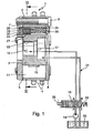
- Figures 1 and 2 show a device 1 for changing the timing an internal combustion engine.
- the device 1 consists essentially of a stator 2 and a concentrically arranged rotor 3.
- a drive wheel 4 is rotatably connected to the stator 2 and in the illustrated Embodiment designed as a sprocket. Likewise conceivable are embodiments of the drive wheel 4 as a belt or gear.
- the stator 2 is rotatably mounted on the rotor 3, wherein on the inner circumferential surface of the stator 2 in the illustrated embodiment five circumferentially spaced apart Recesses 5 are provided.
- the recesses 5 are in radial Direction from the stator 2 and the rotor 3, in the circumferential direction of two side walls 6 of the stator 2 and in the axial direction by a first and a second side cover 7, 8 limited. Each of the recesses 5 is on this Sealed pressure-tight manner.
- the first and second side covers 7, 8 are connected to the stator 2 by means of connecting elements 9, for example screws, connected.
- each vane groove 10th On the outer circumferential surface of the rotor 3 are axially extending vane grooves 10th formed, wherein in each vane groove 10, a radially extending wing 11th is arranged. In each recess 5, a wing 11 extends, wherein the Wing 11 in the radial direction on the stator 2 and in the axial direction on the side covers 7, 8 abut. Each wing 11 divides a recess 5 in two against each other working pressure chambers 12, 13. To a pressure-tight concern to ensure the wing 11 on the stator 2, are between the Nutgen 14 of the wing grooves 10 and the wings 11 leaf spring elements 15 attached, which act on the wing 11 in the radial direction with a force.
- first and second pressure medium lines 16, 17, the first and second pressure chambers 12, 13 via a control valve 18 with a pressure medium pump 19 or a tank 20 are connected.
- This will be an actuator formed, the relative rotation of the stator 2 relative to the Rotor 3 allows.
- either all first pressure chambers 12 with the pressure medium pump 19 and all second pressure chambers 13 be connected to the tank 20 or the exact opposite configuration.
- Be the first pressure chambers 12 with the pressure medium pump 19th and the second pressure chambers 13 connected to the tank 20 so stretch the first pressure chambers 12 at the expense of the second pressure chambers 13th out. This results in a displacement of the wings 11 in the circumferential direction, in the direction shown by the arrow 21.
- the rotor 3 is rotated relative to the stator 2.
- the stator 2 is in the illustrated embodiment by means of a on his Drive wheel 4 attacking, not shown chain drive from the crankshaft driven. Likewise conceivable is the drive of the stator 2 by means of a Belt or gear drive.
- the rotor 3 is a positive, positive or cohesive, for example, by means of press fit or by a screw connection means a central screw, connected to a camshaft, not shown. From the relative rotation of the rotor 3 relative to the stator 2, as a result of the supply or discharge of pressure medium to or from the pressure chambers 12, 13 results a phase shift between camshaft and crankshaft. By targeted introduction and discharge of pressure medium in the pressure chambers 12, 13 can thus the timing of the gas exchange valves of the internal combustion engine be selectively varied.
- the pressure medium lines 16, 17 are in the illustrated embodiment as essentially radially arranged bores extending from a Central bore 22 of the rotor 3 extend to the outer circumferential surface.
- a central valve not shown, arranged be, via which the pressure chambers 12, 13 specifically with the pressure medium pump 19 and the tank 20 can be connected.
- Another Possibility is within the central bore 22 a pressure medium distributor to arrange, the pressure medium lines 16, 17 via pressure medium channels and annular grooves with the terminals of an externally mounted control valve 18 connects.
- the substantially radially extending side walls 6 of the recesses 5 are provided with protrusions 23, which in the circumferential direction in the recesses 5 extend.
- the formations 23 serve as a stop for the Wing 11 and ensure that the pressure chambers 12, 13 with pressure medium can be supplied, even if the rotor 3 one of its two extreme positions relative to the stator 2 occupies, in which the wings 11 at one of Side walls 6 abut.
- the rotor 3 is due to the Alternating and dragging moments that the camshaft exerts on it are uncontrolled moved relative to the stator 2.
- the Camshaft drag torques the rotor relative to the stator in a circumferential direction, which is opposite to the direction of rotation of the stator until this strike against the side walls 6.
- the alternating moments which exerts the camshaft on the rotor 3 to a swinging back and forth of the rotor 3 and thus the wing 11 in the recesses 5, to at least one of the pressure chambers 12, 13 is completely filled with pressure medium. This leads to higher wear and noise developments in the device 1.
- a locking element 24 provided in an axial bore 25 of the rotor 3 .
- a pot-shaped piston 26 is arranged, which by a spring 27 in the axial Direction is applied with a force.
- the spring 27 is supported in the axial Direction on the one hand on a venting element 28 and is with its opposite axial end within the pot-shaped executed Plunger 26 is arranged.
- a backdrop 29 such formed so that the rotor 3 locked relative to the stator 2 in one position can be, which corresponds to the position during the start of the internal combustion engine. In this position, the piston 26 at insufficient pressure medium supply the device 1 urged by the spring 27 in the link 29.
- the pressure medium circuit 31 is also shown. From a tank 20 is by means of a pressure medium pump 19, a pressure medium connection P of a Control valve 18 supplied with pressure medium. At the same time is via a tank connection T pressure medium from the control valve 18 into the tank 20 passed.
- the control valve 18 also has two working ports A, B.
- an electromagnetic Actuator 32 against the spring force of a first spring element 33 acts, the control valve 18 can be placed in three positions. In a first position of the control valve 18, which is a de-energized State of the actuator 32 corresponds to the working port A with the Tank connection T and the pressure medium connection P with the working connection B and thus connected to the second pressure chamber 13.
- both the working connection A and the working connection B are both separated from the pressure medium connection P and from the tank connection T.
- a third position of the control valve 18 is the pressure medium connection P with the working port A and consequently connected to the first pressure chamber 12, while the second pressure chamber 13 via the working port B with the tank connection T is connected.
- an inventive control valve 18 is shown in longitudinal section.
- the essentially hollow-cylindrical valve housing 34 is provided with a radial pressure medium connection P, a radial tank connection T 1 , two working connections A, B and an axial tank connection T 2 .
- the radial ports P, T 1 , A, B are formed as axially spaced first annular grooves 35, which are introduced into the outer circumferential surface of the valve housing 34.
- the first annular grooves 35 are provided with a plurality of first openings 36, which open into the interior of the valve housing 34.
- a likewise substantially hollow cylindrical executed control piston 37 is arranged axially displaceable.
- An axial end of the control piston is pressure-tightly bounded by means of a wall section 37a.
- the wall portion 37a may be integral with the spool or separately configured.
- the control piston 37 can be gerbacht and held against the spring force of the first spring element 33 within two extreme values in an arbitrary position.
- the outer circumferential surface of the control piston 37 is provided with a second, a third and a fourth annular groove 38, 39, 40.
- the second and the third annular groove 38, 39 communicate with the interior of the control piston 37 via second and third openings 41, 42.
- the second annular groove 38 is designed such that it is in any position of the control piston 37 relative to the valve housing 34 with the first openings 36 the first annular groove 35 of the pressure medium connection P communicates.
- pressure medium from the pressure medium connection P passes through the second annular groove 38 and the second openings 41 in the interior of the control piston 37.
- the pressure medium passes through the third openings 42 and the third annular groove 39 to the working port B.
- pressure medium pressure medium from the second pressure chambers 12 is displaced to the working port A and passes through the first openings 36 to the axially arranged tank port T 2 .
- the electromagnetic actuator 32 is energized, the control piston 37 is displaced against the spring force of the first spring element 33.
- the coverage of the first openings 36 of the working port B by a first control edge 43 of the third annular groove 39 increases.
- the coverage of the first openings 36 of the working port A by a second control edge 44 of the control piston 37 increases. If the control piston 37 reaches a central position (not shown), the working connection A is no longer connected to the axial tank connection T 2 due to complete covering of the second control edge 44. Furthermore, neither the working port A nor the working port B communicates with the third annular groove 39. Alternatively, the control piston 37 may be designed such that in the center position both working ports A, B communicate with the third annular groove 39. If the control piston 37 is further displaced counter to the spring force of the first spring element 33, a third control edge 45 releases the first openings 36 of the working connection A to the third annular groove 39. Pressure medium flowing in from the pressure medium connection P now passes exclusively to the working connection A.
- the fourth annular groove 40 communicates both with the working connection B and with the radial tank connection T 1 .
- pressure medium from the pressure medium pump 19 passes into the first pressure chambers 12, which leads to a relative rotation of the rotor 3 to the stator 2.
- the displaced from the second pressure chambers 13 pressure fluid passes through the working port B and the fourth annular groove 40 to the radial tank port T first
- the third control edge 45 and the fourth annular groove 40 may be designed such that during the displacement of the control piston 37 first the working port A with the pressure medium pump 19 and then the working port B are connected to the tank 20.
- both compounds can be prepared simultaneously.
- the control piston 37 is at the axial end remote from the wall section 37a sealed pressure-tight by means of a cup-shaped sleeve 46. This is in Inside the control piston 37 fixed non-positively.
- the sleeve 46 may continue as a point of application of a push rod, not shown, of the actuator 32nd serve.
- the check valve 47 between the working ports A, B and the pressure medium connection P is arranged.
- the axial arrangement of the terminals in the order P - T - A - B or T - P - A - B, wherein the order of the working ports A, B is arbitrary, allows the arrangement of a check valve 47 within the control piston 37. It is only one Check valve 47 is necessary to protect the pressure medium circuit 31. The arrangement of the check valve 47 within the control piston 37 no additional space is needed. Another advantage is that, especially when using the control valve 18 as the central valve, the distance between the place where the pressure pulsations arise and the check valve 47 is minimal. Pressure fluctuations are intercepted practically at the place of origin.
- the check valve 47 consists of a spring-loaded locking body 48 which is urged by means of a second spring element 49 in a seat 50 of the check valve 47.
- the locking body 48, the second spring element 49 and the seat 50 are arranged within a cup-shaped housing 51.
- the second spring element 49 is supported on the bottom of the housing 51.
- the check valve 47 is pressed into the interior of the control piston 37.
- the components are designed such that a pressure-tight, non-positive connection between the inner circumferential surface of the control piston 37 and the housing 51 is produced. It is advantageous within the control piston 37 form an axial stop 52, which serves as a travel limit when pressing the check valve 47 in the control piston 37.
- the check valve 47 can be pressed away controlled. From a certain pressure of the locking body 48 is moved against the spring force of the second spring element 49 and the pressure medium passes through fourth openings 53 which are introduced into the bottom of the housing are to the third openings 42.
Abstract
Description
Die Erfindung betrifft ein Steuerventil für eine Vorrichtung zur Veränderung der Steuerzeiten einer Brennkraftmaschine mit einem im wesentlichen hohlzylindrisch ausgeführten Ventilgehäuse, einem innerhalb des Ventilgehäuses angeordneten und axial verschiebbaren Steuerkolben, einem Druckmittelanschluss, zwei Arbeitsanschlüssen und mindestens einem Tankanschluss, wobei die Arbeitsanschlüsse der Druckmittelanschluss und der Tankanschluss als radiale Anschlüsse ausgebildet sind und die Arbeitsanschlüsse mit dem Druckmittelanschluss und dem Tankanschluss durch axiales Verschieben des Steuerkolbens innerhalb des Ventilgehäuses verbindbar sind.The invention relates to a control valve for a device for changing the Control times of an internal combustion engine with a substantially hollow cylindrical executed valve housing, one disposed within the valve housing and axially displaceable control piston, a pressure medium connection, two working connections and at least one tank connection, whereby the Working connections of the pressure medium connection and the tank connection as radial Connections are formed and the working connections with the pressure medium connection and the tank connection by axial displacement of the control piston can be connected within the valve housing.
In Brennkraftmaschinen werden zur Betätigung der Gaswechselventile Nockenwellen eingesetzt. Nockenwellen sind in der Brennkraftmaschine derart angebracht, dass auf ihnen angebrachte Nocken an Nockenfolgern, beispielsweise Tassenstößeln, Schlepphebeln oder Schwinghebeln, anliegen. Wird eine Nockenwelle in Drehung versetzt, so wälzen die Nocken auf den Nockenfolgern ab, die wiederum die Gaswechselventile betätigen. Durch die Lage und die Form der Nocken sind somit sowohl die Öffnungsdauer als auch die Öffnungsamplitude aber auch die Öffnungs- und Schließzeitpunkte der Gaswechselventile festgelegt.In internal combustion engines, camshafts are used to actuate the gas exchange valves used. Camshafts are such in the internal combustion engine mounted on them mounted cams on cam followers, for example Cup tappets, drag levers or rocker arms, abut. Will one Camshaft set in rotation, so roll the cams on the cam followers off, in turn, actuate the gas exchange valves. By the location and the shape of the cams are thus both the opening duration and the opening amplitude but also the opening and closing times of the gas exchange valves established.
Moderne Motorkonzepte gehen dahin, den Ventiltrieb variabel auszulegen. Einerseits sollen Ventilhub und Ventilöffnungsdauer variabel gestaltbar sein, bis hin zur kompletten Abschaltung einzelner Zylinder. Dafür sind Konzepte wie schaltbare Nockenfolger oder elektrohydraulische oder elektrische Ventilbetätigungen vorgesehen. Weiterhin hat es sich als vorteilhaft herausgestellt, während des Betriebs der Brennkraftmaschine Einfluss auf die Öffnungs- und Schließzeiten der Gaswechselventile nehmen zu können. Dabei ist es insbesondere wünschenswert auf die Öffnungs- bzw. Schließzeitpunkte der Einlass- bzw. Auslassventile getrennt Einfluss nehmen zu können, um beispielsweise gezielt eine definierte Ventilüberschneidung einzustellen. Durch die Einstellung der Öffnungs- bzw. Schließzeitpunkte der Gaswechselventile in Abhängigkeit vom aktuellen Kennfeldbereich des Motors, beispielsweise von der aktuellen Drehzahl bzw. der aktuellen Last, können der spezifische Treibstoffverbrauch gesenkt, das Abgasverhalten positiv beeinflusst, der Motorwirkungsgrad, das Maximaldrehmoment und die Maximalleistung erhöht werden.Modern engine concepts go to design the valve train variable. On the one hand, valve lift and valve opening duration should be variable, up to the complete shutdown of individual cylinders. For that are concepts like switchable cam followers or electro-hydraulic or electric valve actuators intended. Furthermore, it has proved to be advantageous while the operation of the internal combustion engine affects the opening and Closing times of the gas exchange valves to take. It is in particular desirable to the opening and closing times of the intake or exhaust valves to be able to influence separately, for example specifically to set a defined valve overlap. By the attitude the opening and closing times of the gas exchange valves in dependence from the current engine map of the engine, for example, the current Speed or the current load, the specific fuel consumption lowered, the exhaust behavior positively influenced, the engine efficiency, the Maximum torque and maximum power can be increased.
Die beschriebene Variabilität der Gaswechselventilsteuerzeiten wird durch eine relative Änderung der Phasenlage der Nockenwelle zur Kurbelwelle erreicht. Dabei steht die Nockenwelle meist über einen Ketten-, Riemen-, Zahnradtrieb oder gleichwirkende Antriebskonzepte in Antriebsverbindung mjt der Kurbelwelle. Zwischen dem von der Kurbelwelle angetriebenen Ketten-, Riemen- oder Zahnradtrieb und der Nockenwelle ist eine Vorrichtung zur Änderung der Steuerzeiten einer Brennkraftmaschine, im folgenden auch Nockenwellenversteller genannt, angebracht, die das Drehmoment von der Kurbelwelle auf die Nockenwelle überträgt. Dabei ist diese Vorrichtung derart ausgebildet, dass während des Betriebs der Brennkraftmaschine die Phasenlage zwischen Kurbelwelle und Nockenwelle sicher gehalten und, wenn gewünscht, die Nockenwelle in einem gewissen Winkelbereich gegenüber der Kurbelwelle verdreht werden kann.The described variability of the gas exchange valve timing is by a achieved relative change in the phase angle of the camshaft to the crankshaft. The camshaft is usually a chain, belt, gear drive or equivalent drive concepts in drive connection with the crankshaft. Between the driven by the crankshaft chain, belt or Gear drive and the camshaft is a device for changing the timing an internal combustion engine, hereinafter also camshaft adjuster called, attached, the torque from the crankshaft to the camshaft transfers. In this case, this device is designed such that during the operation of the internal combustion engine, the phase angle between the crankshaft and camshaft securely held and, if desired, the camshaft be rotated in a certain angular range relative to the crankshaft can.
In Brennkraftmaschinen mit je einer Nockenwelle für die Einlass- und die Auslassventile können diese mit je einem Nockenwellenversteller ausgerüstet werden. Dadurch können die Öffnungs- und Schließzeitpunkte der Einlass- und Auslassgaswechselventile zeitlich relativ zueinander verschoben und die Ventilüberschneidungen gezielt eingestellt werden.In internal combustion engines, each with a camshaft for the intake and the exhaust valves These can be equipped with a camshaft adjuster. This allows the opening and closing times of the intake and Exhaust gas exchange valves shifted in time relative to each other and the valve overlaps be targeted.
Der Sitz moderner Nockenwellenversteller befindet sich meist am antriebsseitigen Ende der Nockenwelle. Der Nockenwellenversteller kann aber auch auf einer Zwischenwelle, einem nicht rotierenden Bauteil oder der Kurbelwelle angeordnet sein. Er besteht aus einem von der Kurbelwellen angetriebenen, eine feste Phasenbeziehung zu dieser haltenden Antriebsrad, einem in Antriebsverbindung mit der Nockenwelle stehenden Abtriebsteil und einem das Drehmoment vom Antriebsrad auf das Abtriebsteil übertragenden Verstellmechanismus. Das Antriebsrad kann im Fall eines nicht an der Kurbelwelle angeordneten Nockenwellenverstellers als Ketten-, Riemen- oder Zahnrad ausgeführt sein und wird mittels eines Ketten-, eines Riemen- oder eines Zahnradtriebs von der Kurbelwelle angetrieben. Der Verstellmechanismus kann elektrisch, hydraulisch oder pneumatisch betrieben werden.The seat of modern camshaft adjuster is usually located on the drive side End of the camshaft. The camshaft adjuster can also be on an intermediate shaft, a non-rotating component or the crankshaft be. It consists of a crankshaft driven one fixed phase relation to this holding drive wheel, one in drive connection standing with the camshaft output part and a torque from the drive wheel on the driven part transmitted adjusting mechanism. The drive wheel may, in the case of a not arranged on the crankshaft Camshaft adjuster designed as a chain, belt or gear be and is by means of a chain, a belt or a gear drive driven by the crankshaft. The adjustment mechanism can be electrical, operated hydraulically or pneumatically.
Zwei bevorzugte Ausführungsformen hydraulisch verstellbarer Nockenwellenverstellern stellen die sogenannten Axialkolbenversteller und Rotationskolbenversteller dar.Two preferred embodiments of hydraulically adjustable camshaft adjusters provide the so-called Axialkolbenversteller and Rotationskolbenversteller represents.
Bei den Axialkolbenverstellern steht das Antriebsrad mit einem Kolben und dieser mit dem Abtriebsteil jeweils über Schrägverzahnungen in Verbindung. Der Kolben trennt einen durch das Abtriebsteil und das Antriebsrad gebildeten Hohlraum in zwei axial zueinander angeordnete Druckkammern. Wird nun die eine Druckkammer mit Druckmittel beaufschlagt, während die andere Druckkammer mit einem Tank verbunden wird, so verschiebt sich der Kolben in axialer Richtung. Die axiale Verschiebung des Kolbens wird durch die Schrägverzahnungen in eine relative Verdrehung des Antriebsrades zum Abtriebsteil und damit der Nockenwelle zur Kurbelwelle übersetzt.In Axialkolbenverstellern the drive wheel with a piston and this in each case via helical gears in connection with the driven part. The piston separates one formed by the driven part and the drive wheel Cavity in two axially mutually arranged pressure chambers. Will now the a pressure chamber applied with pressure medium, while the other pressure chamber is connected to a tank, so the piston moves in the axial Direction. The axial displacement of the piston is caused by the helical gears in a relative rotation of the drive wheel to the output part and so that the camshaft translates to the crankshaft.
Eine zweite Ausführungsform hydraulischer Nockenwellenversteller sind die sogenannten Rotationskolbenversteller. In diesen ist das Antriebsrad drehfest mit einem Stator verbunden. Der Stator und ein Rotor sind konzentrisch zueinander angeordnet, wobei der Rotor kraft-, form- oder stoffschlüssig, beispielsweise mittels eines Presssitzes, einer Schraub- oder Schweißverbindung mit einer Nockenwelle, einer Verlängerung der Nockenwelle oder einer Zwischenwelle verbunden ist. Im Stator sind mehrere, in Umfangsrichtung beabstandete Hohlräume ausgebildet, die sich ausgehend vom Rotor radial nach außen erstrecken. Die Hohlräume sind in axialer Richtung durch Seitendeckel druckdicht begrenzt. In jeden dieser Hohlräume erstreckt sich ein mit dem Rotor verbundener Flügel, der jeden Hohlraum in zwei Druckkammern teilt. Durch gezieltes Verbinden der einzelnen Druckkammern mit einer Druckmittelpumpe bzw. mit einem Tank kann die Phase der Nockenwelle relativ zur Kurbelwelle eingestellt bzw. gehalten werden.A second embodiment of hydraulic phaser are the so-called rotary piston adjuster. In these, the drive wheel is rotationally fixed connected to a stator. The stator and a rotor are concentric with each other arranged, wherein the rotor non-positively, positively or materially, for example by means of a press fit, a screw or welded connection with a camshaft, an extension of the camshaft or an intermediate shaft connected is. In the stator are several, circumferentially spaced Hollow spaces are formed, starting from the rotor radially outwards extend. The cavities are pressure-tight in the axial direction by side covers limited. In each of these cavities extends one connected to the rotor Wing dividing each cavity into two pressure chambers. Through targeted Connecting the individual pressure chambers with a pressure medium pump or with a tank, the phase of the camshaft relative to the crankshaft be set or held.
Zur Steuerung des Nockenwellenverstellers erfassen Sensoren die Kenndaten des Motors wie beispielsweise den Lastzustand und die Drehzahl. Diese Daten werden einer elektronischen Kontrolleinheit zugeführt, die nach Vergleich der Daten mit einem Kenndatenfeld der Brennkraftmaschine den Zu- und den Abfluss von Druckmittel zu den verschiedenen Druckkammern steuert.To control the camshaft adjuster, sensors record the characteristic data of the engine such as the load condition and the speed. These dates are fed to an electronic control unit, which after comparison of the Data with a characteristic field of the internal combustion engine, the inflow and outflow of pressure medium to the various pressure chambers controls.
Um die Phasenlage der Nockenwelle gegenüber der Kurbelwelle zu verstellen wird in hydraulischen Nockenwellenverstellern eine der zwei gegeneinander wirkenden Druckkammern eines Hohlraums mit einer Druckmittelpumpe und die andere mit dem Tank verbunden. Der Zulauf von Druckmittel zur einen Kammer in Verbindung mit dem Ablauf von Druckmittel von der anderen Kammer verschiebt den die Druckkammern trennenden Kolben in axiale Richtung, wodurch in Axialkolbenverstellern über die Schrägverzahnungen die Nockenwelle relativ zur Kurbelwelle verdreht wird. In Rotationskolbenverstellern wird durch die Druckbeaufschlagung der einen Kammer und die Druckentlastung der anderen Kammer eine Verschiebung des Flügels und damit direkt eine Verdrehung der Nockenwelle zur Kurbelwelle bewirkt. Um die Phasenlage zu halten werden beide Druckkammern entweder mit der Druckmittelpumpe verbunden oder sowohl von der Druckmittelpumpe als auch vom Tank getrennt.To adjust the phasing of the camshaft relative to the crankshaft is one of the two in hydraulic camshaft adjusters against each other acting pressure chambers of a cavity with a pressure medium pump and the other connected to the tank. The inlet of pressure medium on the one hand Chamber in connection with the discharge of pressure medium from the other chamber shifts the piston separating the pressure chambers in the axial direction, whereby in Axialkolbenverstellern on the helical gears, the camshaft is rotated relative to the crankshaft. In rotary piston adjusters is by the pressurization of a chamber and the pressure relief the other chamber a displacement of the wing and thus directly a twist causes the camshaft to the crankshaft. To the phase position too hold both pressure chambers are either connected to the pressure medium pump or separated from both the pressure medium pump and the tank.
Die Steuerung der Druckmittelströme zu bzw. von den Druckkammern erfolgt mittels eines Steuerventils, meist ein 4/3-Proportionalventil. Ein Ventilgehäuse ist mit je einem Anschluss für die Druckkammern (Arbeitsanschluss), einem Anschluss zur Druckmittelpumpe und mindestens einem Anschluss zu einem Tank versehen. Innerhalb des im Wesentlichen hohlzylindrisch ausgeführten Ventilgehäuses ist ein axial verschiebbarer Steuerkolben angeordnet. Der Steuerkolben kann mittels eines elektromagnetischen Stellgliedes entgegen der Federkraft eines Federelements axial in jede Position zwischen zwei definierte Endstellungen gebracht werden. Der Steuerkolben ist weiterhin mit Ringnuten und Steuerkanten versehen, wodurch die einzelnen Druckkammern wahlweise mit der Druckmittelpumpe oder dem Tank verbunden werden können. Ebenso kann eine Stellung des Steuerkolbens vorgesehen sein, in der die Druckmittelkammern sowohl von der Druckmittelpumpe als auch vom Druckmitteltank getrennt sind.The control of the pressure medium flows to or from the pressure chambers takes place by means of a control valve, usually a 4/3 proportional valve. A valve housing is with one connection for the pressure chambers (working connection), one Connection to the pressure medium pump and at least one connection to one Tank provided. Within the substantially hollow cylindrical running Valve housing is arranged an axially displaceable control piston. Of the Control piston can by means of an electromagnetic actuator against the spring force of a spring element axially defined in any position between two End positions are brought. The control piston is still with annular grooves and control edges, whereby the individual pressure chambers can be optionally connected to the pressure medium pump or the tank. Likewise, a position of the control piston may be provided, in which the Pressure medium chambers both from the pressure medium pump and the pressure medium tank are separated.
In der DE 102 15 939 C1 Ist ein derartiges Steuerventil dargestellt. Es besteht
im Wesentlichen aus einem elektromagnetischen Stellantrieb, einem hohlzylindrisch
ausgeführten Ventilgehäuse und einem ebenfalls im Wesentlichen
hohlzylindrisch ausgeführten, innerhalb des Ventilgehäuses axial verschiebbaren
Steuerkolben. Der Steuerkolben kann mittels des Stellantriebs, der gegen
ein Federelement wirkt, innerhalb des Ventilgehäuses in jede beliebige Stellung
verschoben werden.
In die Außenmantelfläche des Ventilgehäuses sind drei axial zueinander
beabstandete Ringnuten eingebracht, in die mehrere in das Innere des Ventilgehäuses
mündende Radialöffnungen eingearbeitet sind. Jede Ringnut bildet
mit den korrespondierenden Radialöffnungen einen radialen Anschluss.
Der hohlzylindrisch ausgeführte Steuerkolben ist an seiner Außenmantelfläche
mit einer Ringnut versehen. Je zwei benachbarte Anschlüsse können mittels
dieser Ringnut, abhängig von der Stellung des Steuerkolbens relativ zum Ventilgehäuse,
miteinander kommunizieren. Weiterhin ist ein vierter, in axialer
Richtung verlaufender Anschluss vorgesehen.
Aufgrund der Geometrie des Steuerkolbens ist es im vorliegenden Fall zwingend
notwendig, dass die in axialer Richtung des Steuerventils gesehnen äußeren
radialen Anschlüsse als Arbeitsanschlüsse genutzt werden, während der
mittlere Anschluss als Druckmittel- oder Tankanschluss genutzt wird.In DE 102 15 939 C1, such a control valve is shown. It consists essentially of an electromagnetic actuator, a hollow cylindrical valve housing and a likewise substantially hollow cylindrical executed within the valve housing axially displaceable control piston. The control piston can be moved by means of the actuator which acts against a spring element, within the valve housing in any position.
In the outer circumferential surface of the valve housing three axially spaced annular grooves are introduced, in which a plurality of opening into the interior of the valve housing radial openings are incorporated. Each annular groove forms a radial connection with the corresponding radial openings.
The hollow cylindrical control piston is provided on its outer circumferential surface with an annular groove. Each two adjacent connections can communicate with each other by means of this annular groove, depending on the position of the control piston relative to the valve housing. Furthermore, a fourth, extending in the axial direction connection is provided.
Due to the geometry of the control piston, it is absolutely necessary in the present case for the outer radial connections, which are stretched in the axial direction of the control valve, to be used as working connections, while the middle connection is used as a pressure medium or tank connection.
Nachteilig wirkt sich in dieser Ausführungsform der Umstand aus, dass innerhalb
des Steuerkolbens nur schwer zusätzliche Bauteile, wie beispielsweise
Filter oder Rückschlagventile, zwischen dem Druckmittelanschluss und den
Arbeitsanschlüssen integriert werden können. Weiterhin müssen jeweils zwei
dieser Bauteile eingesetzt werden, was zu höheren Gesamtkosten und zu einem
höheren Gewicht der Vorrichtung führt.
Speziell für den Einsatz als Zentralventil, bei dem das Steuerventil innerhalb
einer Zentralbohrung des Abtriebsteils eines Nockenwellenverstellers angeordnet
ist, ist diese Art von Ventil ungeeignet, da die Druckmittelzufuhr bzw.
Druckmittelabfuhr zum Druckmittelanschluss bzw. Tankanschluss durch das
Abtriebsteil zu erfolgen hat. Daraus resultieren Mehrkosten bei der Produktion
dieses Bauteils. Weiterhin wird durch die Anordnung des Druckmittelanschlusses
bzw. des Tankanschlusses zwischen den Arbeitsanschlüssen die minimale
axiale Baubreite des Nockenwellenverstellers unnötig vergrößert.A disadvantage in this embodiment is the fact that within the control piston, it is difficult to integrate additional components, such as filters or check valves, between the pressure medium connection and the working connections. Furthermore, two of these components must be used, which leads to higher overall costs and a higher weight of the device.
Especially for use as a central valve, in which the control valve is arranged within a central bore of the driven part of a camshaft adjuster, this type of valve is unsuitable, since the pressure medium supply or pressure fluid removal has to be made to the pressure medium connection or tank connection through the driven part. This results in additional costs in the production of this component. Furthermore, the minimum axial width of the camshaft adjuster is unnecessarily increased by the arrangement of the pressure medium connection or the tank connection between the working ports.
Der Erfindung liegt daher die Aufgabe zugrunde diese geschilderten Nachteile
zu vermeiden und somit ein hydraulisches Steuerventil zu schaffen, wobei innerhalb
des Steuerventils leicht zusätzliche Bauteile integriert werden können
und welches sich in der Ausführungsform als Zentralventil nicht nachteilig auf
die Kosten oder den axialen Bauraum des Nockenwellenverstellers auswirkt.
Erfindungsgemäß wird diese Aufgabe dadurch gelöst, dass in axialer Richtung
des Steuerventils die Anschlüsse in der Reihenfolge Druckmittelanschluss,
Tankanschluss, Arbeitsanschluss, Arbeitsanschluss angeordnet sind.
In einer alternativen Ausführungsform sind in axialer Richtung des Steuerventils
die Anschlüsse in der Reihenfolge Tankanschluss, Druckmittelanschluss,
Arbeitsanschluss, Arbeitsanschluss angeordnet.
Durch die Ausführung des Steuerventils mit unmittelbar benachbarten Arbeitsanschlüssen
und sich axial daran anschließenden Tank- und Druckmittelanschlüssen
kann der Nockenwellenversteller derart ausgebildet sein, dass er
sich in axialer Richtung nur im Bereich der beiden Arbeitsanschlüsse erstreckt,
wodurch der axiale Bauraum des Nockenwellenversteller auf ein Minimum reduziert
werden kann.
Da der Tank- und der Druckmittelanschluss somit außerhalb des Nockenwellenverstellers
angeordnet sind, ist keine aufwändige Zu- bzw. Ableitung des
Druckmittels durch das Abtriebsteil des Nockenwellenverstellers nötig, wodurch
der Nockenwellenversteller kostengünstiger gefertigt werden kann.The invention is therefore based on the object to avoid these disadvantages and thus to provide a hydraulic control valve, within the control valve easily additional components can be integrated and which in the embodiment as a central valve does not adversely affect the cost or the axial space of the camshaft adjuster , According to the invention, this object is achieved in that, in the axial direction of the control valve, the connections are arranged in the order of pressure medium connection, tank connection, working connection, working connection.
In an alternative embodiment, the connections are arranged in the order of tank connection, pressure medium connection, working connection, working connection in the axial direction of the control valve.
Due to the design of the control valve with immediately adjacent working ports and axially adjoining tank and pressure medium connections of the camshaft adjuster can be designed such that it extends in the axial direction only in the region of the two working ports, whereby the axial space of the camshaft adjuster are reduced to a minimum can.
Since the tank and the pressure medium connection are thus arranged outside of the camshaft adjuster, no complex supply or discharge of the pressure medium by the output part of the camshaft adjuster is necessary, whereby the camshaft adjuster can be manufactured more cheaply.
In einer vorteilhaften Weiterbildung der Erfindung ist der Steuerkolben hohl
ausgeführt. Der Druckmittelanschluss kommuniziert über zweite Öffnungen, die
in die Mantelfläche des Steuerkolbens eingebracht sind, in jeder Stellung des
Steuerkolbens relativ zum Ventilgehäuse mit dem Inneren des Steuerkolbens.
Weiterhin kommuniziert abhängig von der Stellung des Steuerkolbens zum
Ventilgehäuse einer oder keiner der Arbeitsanschlüsse mit dem Inneren des
Steuerkolbens, oder es kommuniziert abhängig von der Stellung des Steuerkolbens
zum Ventilgehäuse einer der Arbeitsanschlüsse oder beide Arbeitsanschlüsse
mit dem Inneren des Steuerkolbens.
Druckmittel wird in dieser Anordnung über den Druckmittelanschluss und die
zweiten Öffnungen in das Innere des Steuerkolbens geleitet und gelangt von
dort, abhängig von der Stellung des Steuerkolbens relativ zum Ventilgehäuse,
zu den axial hintereinander angeordneten Arbeitsanschlüssen. Bauteile, wie
Rückschlagventile zwischen den Arbeitsanschlüssen und dem Druckmittelanschluss
oder Filter zwischen dem Druckmittelanschluss und den Arbeitsanschlüssen
können in dem Bauraum innerhalb des Steuerkolbens zwischen den
Anschlüssen angeordnet werden, wobei jeweils nur ein Bauteil angeordnet
werden muss um für beide Arbeitsanschlüsse aktiv zu werden.In an advantageous embodiment of the invention, the control piston is hollow. The pressure medium connection communicates via second openings, which are introduced into the lateral surface of the control piston, in any position of the control piston relative to the valve housing with the interior of the control piston. Further, depending on the position of the control piston to the valve housing, one or none of the working ports communicates with the interior of the control piston, or it communicates with the interior of the control piston depending on the position of the control piston to the valve housing one of the working ports or both working ports.
Pressure medium is conducted in this arrangement via the pressure medium connection and the second openings in the interior of the control piston and passes from there, depending on the position of the control piston relative to the valve housing, to the axially successively arranged working ports. Components such as check valves between the working ports and the pressure medium connection or filter between the pressure medium connection and the working ports can be arranged in the space within the control piston between the terminals, in each case only one component must be arranged to be active for both working connections.
In einer vorteilhaften Weiterbildung der Erfindung ist zwischen dem Druckmittelanschluss
und den Arbeitsanschlüssen ein Rückschlagventil angeordnet.
Während des Betriebs der Brennkraftmaschine ist das hydraulische System
des Nockenwellenverstellers aufgrund der Wechselmomente der Nockenwelle
hohen Druckpulsationen ausgesetzt. Diese Druckspitzen können zur Beschädigung
der Druckmittelpumpe oder anderer Komponenten des Riemen- oder
Kettentriebs führen. Um das Einleiten dieser Druckspitzen in das Hydrauliksystem
der Brennkraftmaschine zu verhindern ist vorgesehen ein Rückschlagventil
zwischen den Arbeitsanschlüssen und dem Druckmittelanschluss des Ventils
anzuordnen. Diese Anordnung ist speziell für Nockenwellenversteller mit Zentralventil
geeignet, da diese Position des Rückschlagventils den geringstmöglichen
Abstand zum Entstehungsort der Druckpulsationen aufweist.
Durch die Anordnung des Rückschlagventils innerhalb des Steuerventils wird
die Drehsteifigkeit des Verstellers und damit seine Positionsstabilität erhöht.In an advantageous development of the invention, a check valve is arranged between the pressure medium connection and the working connections.
During operation of the internal combustion engine, the hydraulic system of the camshaft adjuster is exposed to high pressure pulsations due to the alternating torques of the camshaft. These pressure spikes may damage the fluid pump or other components of the belt or chain drive. In order to prevent the introduction of these pressure peaks in the hydraulic system of the internal combustion engine is provided to arrange a check valve between the working ports and the pressure medium connection of the valve. This arrangement is particularly suitable for camshaft adjuster with central valve, since this position of the check valve has the smallest possible distance to the place of origin of the pressure pulsations.
The arrangement of the check valve within the control valve, the torsional stiffness of the adjuster and thus its positional stability is increased.
Weitere Merkmale der Erfindung ergeben sich aus der nachfolgenden Beschreibung und aus den Zeichnungen, in denen Ausführungsbeispiele der Erfindung vereinfacht dargestellt sind. Es zeigen:
Figur 1- einen Längsschnitt durch eine Vorrichtung zur Veränderung der Steuerzeiten einer Brennkraftmaschine mit Druckmittelkreislauf,
Figur 2- einen Querschnitt durch die in
Figur 1 dargestellte Vorrichtung entlang der Linie II-II, Figur 3- einen Längsschnitt durch ein erfindungsgemäßes Steuerventil.
- FIG. 1
- a longitudinal section through a device for changing the timing of an internal combustion engine with pressure medium circuit,
- FIG. 2
- a cross-section through the device shown in Figure 1 along the line II-II,
- FIG. 3
- a longitudinal section through a control valve according to the invention.
Die Figuren 1 und 2 zeigen eine Vorrichtung 1 zur Veränderung der Steuerzeiten
einer Brennkraftmaschine. Die Vorrichtung 1 besteht im Wesentlichen aus
einem Stator 2 und einem konzentrisch dazu angeordneten Rotor 3. Ein Antriebsrad
4 ist drehfest mit dem Stator 2 verbunden und in der dargestellten
Ausführungsform als Kettenrad ausgebildet. Ebenso denkbar sind Ausführungsformen
des Antriebsrads 4 als Riemen oder Zahnrad. Der Stator 2 ist
drehbar auf dem Rotor 3 gelagert, wobei an der Innenmantelfläche des Stators
2 in der dargestellten Ausführungsform fünf in Umfangsrichtung beabstandete
Ausnehmungen 5 vorgesehen sind. Die Ausnehmungen 5 werden in radialer
Richtung vom Stator 2 und dem Rotor 3, in Umfangsrichtung von zwei Seitenwänden
6 des Stators 2 und in axialer Richtung durch einen ersten und einen
zweiten Seitendeckel 7, 8 begrenzt. Jede der Ausnehmungen 5 ist auf diese
Weise druckdicht verschlossen. Der erste und der zweite Seitendeckel 7, 8
sind mit dem Stator 2 mittels Verbindungselementen 9, beispielsweise Schrauben,
verbunden.Figures 1 and 2 show a
An der Außenmantelfläche des Rotors 3 sind axial verlaufende Flügelnuten 10
ausgebildet, wobei in jeder Flügelnut 10 ein sich radial erstreckender Flügel 11
angeordnet ist. In jede Ausnehmung 5 erstreckt sich ein Flügel 11, wobei die
Flügel 11 in radialer Richtung am Stator 2 und in axialer Richtung an den Seitendeckeln
7, 8 anliegen. Jeder Flügel 11 unterteilt eine Ausnehmung 5 in zwei
gegeneinander arbeitende Druckkammern 12, 13. Um ein druckdichtes Anliegen
der Flügel 11 am Stator 2 zu gewährleisten, sind zwischen den Nutgründen
14 der Flügelnuten 10 und den Flügeln 11 Blattfederelemente 15 angebracht,
die den Flügel 11 in radialer Richtung mit einer Kraft beaufschlagen.On the outer circumferential surface of the
Mittels ersten und zweiten Druckmittelleitungen 16, 17 können die ersten und
zweiten Druckkammern 12, 13 über ein Steuerventil 18 mit einer Druckmittelpumpe
19 oder einem Tank 20 verbunden werden. Dadurch wird ein Stellantrieb
ausgebildet, der eine Relativverdrehung des Stators 2 gegenüber dem
Rotor 3 ermöglicht. Dabei ist vorgesehen, dass entweder alle ersten Druckkammern
12 mit der Druckmittelpumpe 19 und alle zweiten Druckkammern 13
mit dem Tank 20 verbunden werden bzw. die genau entgegen gesetzte Konfiguration.
Werden die ersten Druckkammern 12 mit der Druckmittelpumpe 19
und die zweiten Druckkammern 13 mit dem Tank 20 verbunden, so dehnen
sich die ersten Druckkammern 12 auf Kosten der zweiten Druckkammern 13
aus. Daraus resultiert eine Verschiebung der Flügel 11 in Umfangsrichtung, in
der durch den Pfeil 21 dargestellten Richtung. Durch das Verschieben der Flügel
11 wird der Rotor 3 relativ zum Stator 2 verdreht.By means of first and second
Der Stator 2 wird in der dargestellten Ausführungsform mittels eines an seinem
Antriebsrad 4 angreifenden, nicht dargestellten Kettentriebs von der Kurbelwelle
angetrieben. Ebenso denkbar ist der Antrieb des Stators 2 mittels eines
Riemen- oder Zahnradtriebs. Der Rotor 3 ist kraft-, form- oder stoffschlüssig,
beispielsweise mittels Presssitz oder durch eine Schraubverbindung mittels
einer Zentralschraube, mit einer nicht dargestellten Nockenwelle verbunden.
Aus der Relativverdrehung des Rotors 3 relativ zum Stator 2, als Folge des Zu-
bzw. Ableitens von Druckmittel zu bzw. aus den Druckkammern 12, 13, resultiert
eine Phasenverschiebung zwischen Nockenwelle und Kurbelwelle. Durch
gezieltes Ein- bzw. Ableiten von Druckmittel in die Druckkammern 12, 13 können
somit die Steuerzeiten der Gaswechselventile der Brennkraftmaschine
gezielt variiert werden.The
Die Druckmittelleitungen 16, 17 sind in der dargestellten Ausführungsform als
im Wesentlichen radial angeordnete Bohrungen ausgeführt, die sich von einer
Zentralbohrung 22 des Rotors 3 zur dessen äußerer Mantelfläche erstrecken.
Innerhalb der Zentralbohrung 22 kann ein nicht dargestelltes Zentralventil angeordnet
sein, über welches die Druckkammern 12, 13 gezielt mit der Druckmittelpumpe
19 bzw. dem Tank 20 verbunden werden können. Eine weitere
Möglichkeit besteht darin, innerhalb der Zentralbohrung 22 einen Druckmittelverteiler
anzuordnen, der die Druckmittelleitungen 16, 17 über Druckmittelkanäle
und Ringnuten mit den Anschlüssen eines extern angebrachten Steuerventils
18 verbindet. The pressure
Die im Wesentlichen radial verlaufenden Seitenwände 6 der Ausnehmungen 5
sind mit Ausformungen 23 versehen, die in Umfangsrichtung in die Ausnehmungen
5 hineinreichen. Die Ausformungen 23 dienen als Anschlag für die
Flügel 11 und gewährleisten, dass die Druckkammern 12, 13 mit Druckmittel
versorgt werden können, selbst wenn der Rotor 3 eine seiner beiden Extremstellungen
relativ zum Stator 2 einnimmt, in denen die Flügel 11 an einer der
Seitenwände 6 anliegen.The substantially radially extending
Bei ungenügender Druckmittelversorgung der Vorrichtung 1, beispielsweise
während der Startphase der Brennkraftmaschine, wird der Rotor 3 aufgrund der
Wechsel- und Schleppmomente, die die Nockenwelle auf diesen ausübt unkontrolliert
relativ zum Stator 2 bewegt. In einer ersten Phase drängen die
Schleppmomente der Nockenwelle den Rotor relativ zum Stator in eine Umfangsrichtung,
die entgegengesetzt zur Drehrichtung des Stators liegt, bis diese
an den Seitenwänden 6 anschlagen. Im Folgenden führen die Wechselmomente,
die die Nockenwelle auf den Rotor 3 ausübt zu einem Hin- und Herschwingen
des Rotors 3 und damit der Flügel 11 in den Ausnehmungen 5, bis
zumindest eine der Druckkammern 12, 13 vollständig mit Druckmittel befüllt ist.
Dies führt zu höherem Verschleiß und zu Geräuschentwicklungen in der Vorrichtung
1. Um dies zu verhindern ist in der Vorrichtung 1 ein Verriegelungselement
24 vorgesehen. Dazu ist in einer Axialbohrung 25 des Rotors 3 ein
topfförmiger Kolben 26 angeordnet, welcher durch eine Feder 27 in axialer
Richtung mit einer Kraft beaufschlagt wird. Die Feder 27 stützt sich in axialer
Richtung auf der einen Seite an einem Entlüftungselement 28 ab und ist mit
ihrem davon abgewandten axialen Ende innerhalb des topfförmig ausgeführten
Kolbens 26 angeordnet. Im ersten Seitendeckel 7 ist eine Kulisse 29 derart
ausgebildet, dass der Rotor 3 relativ zum Stator 2 in einer Position verriegelt
werden kann, die der Position während des Starts der Brennkraftmaschine entspricht.
In dieser Stellung wird der Kolben 26 bei ungenügender Druckmittelversorgung
der Vorrichtung 1 mittels der Feder 27 in die Kulisse 29 gedrängt.
Weiterhin sind Mittel vorgesehen, um den Kolben 26 bei ausreichender Versorgung
der Vorrichtung 1 mit Druckmittel in die Axialbohrung 25 zurückzudrängen
und damit die Verriegelung aufzuheben. Dies wird üblicherweise mit
Druckmittel bewerkstelligt, welches über nicht dargestellte Druckmittelleitungen
in eine Aussparung 30 geleitet wird, welche am deckelseitigen Stirnende des
Kolbens 26 ausgebildet ist. Um Leckageöl aus dem Federraum der Axialbohrung
25 ableiten zu können ist das Entlüftungselement 28 mit axial verlaufenden
Nuten versehen, entlang derer das Druckmittel zu einer Bohrung im zweiten
Seitendeckel 8 geleitet werden kann.With insufficient pressure medium supply of the
In Figur 1 ist zusätzlich der Druckmittelkreislauf 31 dargestellt. Aus einem Tank
20 wird mittels einer Druckmittelpumpe 19 ein Druckmittelanschluss P eines
Steuerventils 18 mit Druckmittel versorgt. Gleichzeitig wird über einen Tankanschluss
T Druckmittel vom Steuerventil 18 in den Tank 20 geleitet. Das Steuerventil
18 besitzt weiterhin zwei Arbeitsanschlüsse A, B. Mittels eines elektromagnetischen
Stellgliedes 32, das gegen die Federkraft eines ersten Federelements
33 wirkt, kann das Steuerventil 18 in drei Stellungen gebracht werden.
In einer ersten Stellung des Steuerventils 18, die einem unbestromten
Zustand des Stellgliedes 32 entspricht, wird der Arbeitsanschluss A mit dem
Tankanschluss T und der Druckmittelanschluss P mit dem Arbeitsanschluss B
und somit mit der zweiten Druckkammer 13 verbunden. In einer mittleren Stellung
sind sowohl der Arbeitsanschluss A als auch der Arbeitsanschluss B sowohl
vom Druckmittelanschluss P als auch vom Tankanschluss T getrennt. In
einer dritten Stellung des Steuerventils 18 ist der Druckmittelanschluss P mit
dem Arbeitsanschluss A und folglich mit der ersten Druckkammer 12 verbunden,
während die zweite Druckkammer 13 über den Arbeitsanschluss B mit
dem Tankanschluss T verbunden ist.In Figure 1, the
In Figur 3 ist ein erfindungsgemäßes Steuerventil 18 im Längsschnitt dargestellt.
Das im wesentlichen hohlzylindrisch ausgeführte Ventilgehäuse 34 ist mit
einem radialen Druckmittelanschluss P, einem radialen Tankanschluss T1, zwei
Arbeitsanschlüssen A, B und einem axialen Tankanschluss T2 versehen. Die
radialen Anschlüsse P, T1, A, B sind als axial zueinander beabstandete erste
Ringnuten 35 ausgebildet, die in die Außenmantelfläche des Ventilgehäuses
34 eingebracht sind. Die ersten Ringnuten 35 sind mit mehreren ersten Öffnungen
36 versehen, die in das Innere des Ventilgehäuses 34 münden.
Innerhalb des Ventilgehäuses 34 ist ein ebenfalls im Wesentlichen hohlzylindrisch
ausgeführter Steuerkolben 37 axial verschiebbar angeordnet. Ein axiales
Ende des Steuerkolbens ist mittels eines Wandabschnittes 37a druckdicht begrenzt.
Der Wandabschnitt 37a kann einteilig mit dem Steuerkolben oder separat
dazu ausgeführt sein. Mittels eines nicht dargestellten Stellgliedes 32 kann
der Steuerkolben 37 gegen die Federkraft des ersten Federelements 33 innerhalb
zweier Extremwerte in eine beliebige Position gerbacht und gehalten werden.
Die Außenmantelfläche des Steuerkolbens 37 ist mit einer zweiten, einer dritten
und einer vierten Ringnut 38, 39, 40 versehen. Die zweite und die dritte
Ringnut 38, 39 kommunizieren über zweite und dritte Öffnungen 41, 42 mit dem
Inneren des Steuerkolbens 37. Die zweite Ringnut 38 ist derart ausgebildet,
dass sie in jeder Stellung des Steuerkolbens 37 relativ zum Ventilgehäuse 34
mit den ersten Öffnungen 36 der ersten Ringnut 35 des Druckmittelanschlusses
P kommuniziert.In Figure 3, an
Within the
The outer circumferential surface of the
Während des Betriebs der Brennkraftmaschine gelangt Druckmittel vom
Druckmittelanschluss P über die zweite Ringnut 38 und die zweiten Öffnungen
41 in das Innere des Steuerkolbens 37. In der in Figur 3 dargestellten ersten
Stellung des Steuerkolbens 37 gelangt das Druckmittel über die dritten Öffnungen
42 und die dritte Ringnut 39 zum Arbeitsanschluss B. Durch Beaufschlagung
der zweiten Druckkammern 13 über den Arbeitsanschluss B mit Druckmittel
wird Druckmittel aus den zweiten Druckkammern 12 zum Arbeitsanschluss A
verdrängt und gelangt über dessen erste Öffnungen 36 zum axial angeordneten
Tankanschluss T2.
Wird das elektromagnetische Stellglied 32 bestromt so wird der Steuerkolben
37 gegen die Federkraft des ersten Federelements 33 verschoben. Als Folge
nimmt die Überdeckung der ersten Öffnungen 36 des Arbeitsanschlusses B
durch eine erste Steuerkante 43 der dritten Ringnut 39 zu. Gleichermaßen
nimmt auch die Überdeckung der ersten Öffnungen 36 des Arbeitsanschlusses
A durch eine zweite Steuerkante 44 des Steuerkolbens 37 zu. Erreicht der
Steuerkolben 37 eine nicht dargestellte Mittelstellung so ist der Arbeitsanschluss
A, durch vollständige Überdeckung der zweiten Steuerkante 44, nicht
mehr mit dem axialen Tankanschluss T2 verbunden. Weiterhin kommuniziert
weder der Arbeitsanschluss A noch der Arbeitsanschluss B mit der dritten
Ringnut 39.
Alternativ kann der Steuerkolben 37 derart ausgeführt sein, dass in der Mittelstellung
beide Arbeitsanschlüsse A, B mit der dritten Ringnut 39 kommunizieren.
Wird der Steuerkolben 37 weiter entgegen der Federkraft des ersten Federelements
33 verschoben so gibt eine dritte Steuerkante 45 die ersten Öffnungen
36 des Arbeitsanschlusses A zur dritten Ringnut 39 frei. Vom Druckmittelanschluss
P einströmendes Druckmittel gelangt nun ausschließlich zum Arbeitsanschluss
A. Gleichzeitig kommuniziert die vierte Ringnut 40 sowohl mit
dem Arbeitsanschluss B als auch mit dem radialen Tankanschluss T1. Auf diese
Weise gelangt Druckmittel von der Druckmittelpumpe 19 in die ersten
Druckkammern 12, was zu einer relativen Verdrehung des Rotors 3 zum Stator
2 führt. Das aus den zweiten Druckkammern 13 verdrängte Druckmittel gelangt
über den Arbeitsanschluss B und die vierte Ringnut 40 zum radialen Tankanschluss
T1. Die dritte Steuerkante 45 und die vierte Ringnut 40 können derart
ausgeführt sein, dass während der Verschiebung des Steuerkolbens 37 zuerst
der Arbeitsanschluss A mit der Druckmittelpumpe 19 und dann der Arbeitsanschluss
B mit dem Tank 20 verbunden werden. Alternativ könne auch beide
Verbindungen gleichzeitig hergestellt werden.During operation of the internal combustion engine pressure medium from the pressure medium connection P passes through the second
When the
Alternatively, the
If the
Der Steuerkolben 37 ist am vom Wandabschnitt 37a abgewandten axialen Ende
mittels einer topfförmigen Hülse 46 druckdicht verschlossen. Diese ist im
Inneren des Steuerkolbens 37 kraftschlüssig fixiert. Die Hülse 46 kann weiterhin
als Angriffspunkt einer nicht dargestellten Stößelstange des Stellglieds 32
dienen.The
Während des Betriebs der Brennkraftmaschine werden aufgrund der Wechselmomente der Nockenwelle Druckpulsationen innerhalb der Vorrichtung 1 generiert. Dabei treten Druckspitzen auf, die in den Druckmittelkreislauf 31 übertragen werden und andere Verbraucher schädigen können. Dies kann durch die Anordnung eines Rückschlagventils 47 im Druckmittelkreislauf 31 unterbunden werden.During operation of the internal combustion engine are due to the alternating torques the camshaft pressure pulsations within the device. 1 generated. In this case, pressure peaks occur in the pressure medium circuit 31st and harm other consumers. This can by the arrangement of a check valve 47 in the pressure medium circuit 31st be prevented.
In einer Ausführungsform des Steuerventils (37) ist das Rückschlagventil 47
zwischen den Arbeitsanschlüssen A, B und dem Druckmittelanschluss P angeordnet.
Die axiale Anordnung der Anschlüsse in der Reihenfolge P - T - A - B
oder T - P - A - B, wobei die Reihenfolge der Arbeitsanschlüsse A, B beliebig
ist, ermöglicht die Anordnung eines Rückschlagventils 47 innerhalb des Steuerkolbens
37. Dabei ist nur ein Rückschlagventil 47 nötig, um den Druckmittelkreislauf
31 zu schützen. Durch die Anordnung des Rückschlagventils 47 innerhalb
des Steuerkolbens 37 wird kein zusätzlicher Bauraum benötigt. Ein
weiterer Vorteil liegt darin, dass, speziell bei Verwendung des Steuerventils 18
als Zentralventil, die Strecke zwischen dem Ort an dem die Druckpulsationen
entstehen und dem Rückschlagventil 47 minimal ist. Druckschwankungen werden
praktisch am Entstehungsort abgefangen.
Das Rückschlagventil 47 besteht aus einem federbelasteten Sperrkörper 48,
der mittels eines zweiten Federelements 49 in einen Sitz 50 des Rückschlagventils
47 gedrängt wird. Der Sperrkörper 48, das zweite Federelement 49 und
der Sitz 50 sind innerhalb eines topfförmigen Gehäuses 51 angeordnet. Das
zweite Federelement 49 stützt sich am Boden des Gehäuses 51 ab.
Während der Montage wird das Rückschlagventil 47 in das Innere des Steuerkolbens
37 eingepresst. Dabei sind die Bauteile derart ausgebildet, dass eine
druckdichte, kraftschlüssige Verbindung zwischen der inneren Mantelfläche
des Steuerkolbens 37 und dem Gehäuse 51 hergestellt wird. Dabei ist es vorteilhaft
innerhalb des Steuerkolbens 37 einen Axialanschlag 52 auszubilden,
der als Wegbegrenzung beim Einpressen des Rückschlagventils 47 in den
Steuerkolben 37 dient. Alternativ kann das Rückschlagventil 47 weggesteuert
eingepresst werden.
Vom Druckanschluss P einströmendes Druckmittel gelangt über die zweiten
Öffnungen 41 in das Innere des Steuerkolbens 37. Ab einem gewissen Druck
wird der Sperrkörper 48 gegen die Federkraft des zweiten Federelements 49
verschoben und das Druckmittel gelangt über vierte Öffnungen 53, die in den
Boden des Gehäuses eingebracht sind, zu den dritten Öffnungen 42. In one embodiment of the control valve (37), the check valve 47 between the working ports A, B and the pressure medium connection P is arranged. The axial arrangement of the terminals in the order P - T - A - B or T - P - A - B, wherein the order of the working ports A, B is arbitrary, allows the arrangement of a check valve 47 within the
The check valve 47 consists of a spring-loaded locking body 48 which is urged by means of a second spring element 49 in a
During assembly, the check valve 47 is pressed into the interior of the
From a certain pressure of the locking body 48 is moved against the spring force of the second spring element 49 and the pressure medium passes through
- 11
- Vorrichtungcontraption
- 22
- Statorstator
- 33
- Rotorrotor
- 44
- Antriebsraddrive wheel
- 55
- Ausnehmungenrecesses
- 66
- SeitenwandSide wall
- 77
- erster Seitendeckelfirst side cover
- 88th
- zweiter Seitendeckelsecond side cover
- 99
- Verbindungselementconnecting element
- 1010
- Flügelnutvane
- 1111
- Flügelwing
- 1212
- erste Druckkammerfirst pressure chamber
- 1313
- zweite Druckkammersecond pressure chamber
- 1414
- Nutgrundgroove base
- 1515
- BlattfederelementLeaf spring element
- 1616
- erste Druckmittelleitungfirst pressure medium line
- 1717
- zweite Druckmittelleitungsecond pressure medium line
- 1818
- Steuerventilcontrol valve
- 1919
- DruckmittelpumpeHydraulic pump
- 2020
- Tanktank
- 2121
- Pfeilarrow
- 2222
- Zentralbohrungcentral bore
- 2323
- Ausformungenformations
- 2424
- Verriegelungselementlocking element
- 2525
- Axialbohrungaxial bore
- 2626
- Kolbenpiston
- 2727
- Federfeather
- 2828
- EntlüftungselementA vent
- 2929
- Kulissescenery
- 3030
- Aussparungrecess
- 3131
- DruckmittelkreislaufPressure medium circuit
- 3232
- Stellgliedactuator
- 3333
- erstes Federelementfirst spring element
- 3434
- Ventilgehäusevalve housing
- 3535
- erste Ringnutfirst ring groove
- 3636
- erste Öffnungenfirst openings
- 3737
- Steuerkolbenspool
- 37a37a
- Wandabschnittwall section
- 3838
- zweite Ringnutsecond annular groove
- 3939
- dritte Ringnutthird annular groove
- 4040
- vierte Ringnutfourth ring groove
- 4141
- zweite Öffnungsecond opening
- 4242
- dritte Öffnungthird opening
- 4343
- erste Steuerkantefirst control edge
- 4444
- zweite Steuerkantesecond control edge
- 4545
- dritte Steuerkantethird control edge
- 4646
- Hülseshell
- 4747
- Rückschlagventilcheck valve
- 4848
- Sperrkörperblocking body
- 4949
- zweites Federelementsecond spring element
- 5050
- SitzSeat
- 5151
- Gehäusecasing
- 5252
- Axialanschlagaxial stop
- 5353
- vierte Öffnungfourth opening
- PP
- DruckmittelanschlussPressure medium connection
- TT
- Tankanschlusstank connection
- T1 T 1
- radialer Tankanschlussradial tank connection
- T2 T 2
- axialer Tankanschlussaxial tank connection
- AA
- erster Arbeitsanschlussfirst work connection
- BB
- zweiter Arbeitsanschlusssecond work connection
Claims (7)
Applications Claiming Priority (4)
| Application Number | Priority Date | Filing Date | Title |
|---|---|---|---|
| DE102004023976 | 2004-05-14 | ||
| DE102004023976 | 2004-05-14 | ||
| DE102004038252 | 2004-08-06 | ||
| DE200410038252 DE102004038252A1 (en) | 2004-05-14 | 2004-08-06 | Control valve for a device for changing the timing of an internal combustion engine |
Publications (2)
| Publication Number | Publication Date |
|---|---|
| EP1596041A2 true EP1596041A2 (en) | 2005-11-16 |
| EP1596041A3 EP1596041A3 (en) | 2008-07-16 |
Family
ID=34935007
Family Applications (1)
| Application Number | Title | Priority Date | Filing Date |
|---|---|---|---|
| EP20050007929 Ceased EP1596041A3 (en) | 2004-05-14 | 2005-04-12 | Control valve for a camshaft timing phaser in an internal combustion engine |
Country Status (4)
| Country | Link |
|---|---|
| US (1) | US7533695B2 (en) |
| EP (1) | EP1596041A3 (en) |
| JP (1) | JP2005325841A (en) |
| DE (1) | DE102004038252A1 (en) |
Cited By (20)
| Publication number | Priority date | Publication date | Assignee | Title |
|---|---|---|---|---|
| WO2007025630A1 (en) * | 2005-09-01 | 2007-03-08 | Schaeffler Kg | Control valve for a device for changing the control times of an internal combustion engine |
| WO2007125050A2 (en) * | 2006-05-03 | 2007-11-08 | Schaeffler Kg | Valve for a camshaft adjuster |
| WO2008077662A1 (en) * | 2006-12-22 | 2008-07-03 | Schaeffler Kg | Valve for a camshaft adjuster |
| DE102007053688A1 (en) | 2007-11-10 | 2009-05-14 | Schaeffler Kg | Control valve assembly for camshaft adjuster of internal combustion engine, comprises hollow cylindrical valve housing and hydraulic control valve for controlling pressure medium flow |
| WO2010089239A1 (en) | 2009-02-09 | 2010-08-12 | Schaeffler Technologies Gmbh & Co. Kg | Control valves for controlling pressure medium flows |
| DE102009024026A1 (en) | 2009-06-05 | 2010-12-09 | Schaeffler Technologies Gmbh & Co. Kg | Control valve for controlling pressure medium flows with integrated non-return valve |
| WO2011051378A2 (en) | 2009-10-29 | 2011-05-05 | Schaeffler Technologies Gmbh & Co. Kg | Fastening assembly of a camshaft adjuster |
| DE102009054051A1 (en) | 2009-11-20 | 2011-05-26 | Schaeffler Technologies Gmbh & Co. Kg | Switchable device for pressure supply with passive additional pressure accumulator |
| DE102009054050A1 (en) | 2009-11-20 | 2011-05-26 | Schaeffler Technologies Gmbh & Co. Kg | Switchable device for supplying pressure to lubricating oil system of internal-combustion engine, has braking device switched into switched-off condition, in which rotating motion of screw pillar is not prevented |
| DE102009054053A1 (en) | 2009-11-20 | 2011-05-26 | Schaeffler Technologies Gmbh & Co. Kg | Pressure reservoir for hydraulic system, has housing, movable element and energy storage, where movable element is arranged within housing |
| DE102009054055A1 (en) | 2009-11-20 | 2011-05-26 | Schaeffler Technologies Gmbh & Co. Kg | Switchable device for pressure supply |
| DE102009054052A1 (en) | 2009-11-20 | 2011-05-26 | Schaeffler Technologies Gmbh & Co. Kg | Switchable device for pressure supply |
| EP2363579A1 (en) * | 2010-02-24 | 2011-09-07 | Delphi Technologies, Inc. | Oil flow control valve with two check valves |
| US8118060B2 (en) | 2007-07-18 | 2012-02-21 | Schaeffer Technologies GmbH & Co. KG | Valve part of a hydraulic control valve for controlling flows of pressurized medium |
| US8272403B2 (en) | 2007-07-18 | 2012-09-25 | Schaeffler Technologies AG & Co. KG | Valve part of a hydraulic control valve |
| WO2013174531A1 (en) * | 2012-05-25 | 2013-11-28 | Schaeffler Technologies AG & Co. KG | Control valve for a camshaft adjuster |
| WO2014075665A1 (en) * | 2012-11-13 | 2014-05-22 | Schaeffler Technologies AG & Co. KG | Control valve for a hydraulic apparatus with locking facility |
| EP2860363A1 (en) * | 2013-08-27 | 2015-04-15 | Aisin Seiki Kabushiki Kaisha | Control valve and attachment structure of control valve |
| DE102014207989A1 (en) | 2014-04-29 | 2015-10-29 | Schaeffler Technologies AG & Co. KG | Hydraulic phaser of a camshaft |
| CN107208504A (en) * | 2015-01-15 | 2017-09-26 | 舍弗勒技术股份两合公司 | Control valve with flow pass |
Families Citing this family (42)
| Publication number | Priority date | Publication date | Assignee | Title |
|---|---|---|---|---|
| DE102004036096B4 (en) * | 2004-07-24 | 2017-09-14 | Schaeffler Technologies AG & Co. KG | Control valve for a device for changing the timing of an internal combustion engine |
| DE102005047641A1 (en) * | 2005-10-05 | 2007-04-12 | Schaeffler Kg | Control valve for a camshaft adjuster |
| DE102006008861B4 (en) * | 2006-02-25 | 2008-08-14 | Hofer Mechatronik Gmbh | Camshaft adjuster for an internal combustion engine |
| DE102006031595A1 (en) * | 2006-07-08 | 2008-02-21 | Schaeffler Kg | Hydraulic clamping system |
| DE102006061104A1 (en) | 2006-12-22 | 2008-06-26 | Schaeffler Kg | Method for determining a duty cycle for a valve of a camshaft adjuster |
| DE102007015333B4 (en) | 2007-03-30 | 2020-08-27 | Schaeffler Technologies AG & Co. KG | Control valve and manufacturing method for the control valve |
| EP2006499A3 (en) * | 2007-06-07 | 2008-12-31 | Delphi Technologies, Inc. | Locking mechanism for a camshaft phaser |
| DE102008004591A1 (en) * | 2008-01-16 | 2009-07-23 | Schaeffler Kg | Hydraulic control valve with integrated check valve |
| EP2136041B1 (en) | 2008-06-19 | 2011-06-08 | Hydraulik-Ring GmbH | Valve to shift a camshaft |
| DE102008030058B4 (en) | 2008-06-27 | 2010-06-17 | Hydraulik-Ring Gmbh | Camshaft adjusting device and suitable valve for it |
| DE102008030057B4 (en) | 2008-06-27 | 2018-01-25 | Hilite Germany Gmbh | Camshaft adjustment device |
| WO2010007712A1 (en) | 2008-07-17 | 2010-01-21 | 三菱電機株式会社 | Solenoid valve for variable valve timing device and variable valve timing system |
| US20100084019A1 (en) * | 2008-10-08 | 2010-04-08 | Schaeffler Kg | Central spool valve |
| DE102009022869A1 (en) * | 2009-05-27 | 2010-12-09 | Hydraulik-Ring Gmbh | Vane phaser system |
| JP2011064105A (en) * | 2009-09-16 | 2011-03-31 | Hitachi Automotive Systems Ltd | Valve timing control apparatus for internal combustion engine |
| DE102009050779B4 (en) | 2009-10-27 | 2016-05-04 | Hilite Germany Gmbh | Schwenkmotornockenwellenversteller with a friction disc and mounting method |
| DE102009052841A1 (en) * | 2009-11-13 | 2011-05-19 | Hydraulik-Ring Gmbh | camshafts use |
| KR101134973B1 (en) * | 2009-11-19 | 2012-04-09 | 기아자동차주식회사 | Engine brake and engine provided with the same |
| DE102010009401A1 (en) * | 2010-02-26 | 2011-09-01 | Schaeffler Technologies Gmbh & Co. Kg | Proportional valve, in particular for a camshaft adjuster |
| DE102010045358A1 (en) | 2010-04-10 | 2011-10-13 | Hydraulik-Ring Gmbh | Schwenkmotornockenwellenversteller with a hydraulic valve |
| DE102010019005B4 (en) | 2010-05-03 | 2017-03-23 | Hilite Germany Gmbh | Schwenkmotorversteller |
| DE102010023863A1 (en) | 2010-06-15 | 2011-12-15 | Hydraulik-Ring Gmbh | Assembled camshaft for camshaft drive system for actuating charge-cycle valve of internal combustion engine, has piston supported opposite to camshaft insert and directly mounted within pipe for pivoting rotor against stator |
| DE102010032251A1 (en) * | 2010-07-26 | 2012-01-26 | Schaeffler Technologies Gmbh & Co. Kg | Check valve and hydraulic valve with built-in check valve |
| DE102010050813A1 (en) | 2010-11-09 | 2012-05-10 | Schaeffler Technologies Gmbh & Co. Kg | Control piston i.e. cylindrical body, for 4/3-way central valve utilized in camshaft adjusting device for actuating camshaft of petrol engine for automobile, has air- and oil-permeable separation structure arranged in cavity filled with oil |
| JP5152313B2 (en) * | 2010-12-10 | 2013-02-27 | 株式会社デンソー | Valve timing adjustment device |
| US8695548B2 (en) | 2010-12-10 | 2014-04-15 | Denso Corporation | Valve timing control apparatus |
| DE102010061337B4 (en) | 2010-12-20 | 2015-07-09 | Hilite Germany Gmbh | Hydraulic valve for a Schwenkmotorversteller |
| US8662039B2 (en) | 2011-03-16 | 2014-03-04 | Delphi Technologies, Inc. | Camshaft phaser with coaxial control valves |
| JP2012241740A (en) * | 2011-05-16 | 2012-12-10 | Denso Corp | Solenoid valve and hydraulic control device |
| JP5360173B2 (en) * | 2011-09-15 | 2013-12-04 | 株式会社デンソー | Valve timing adjustment device |
| DE102011084059B4 (en) | 2011-10-05 | 2016-12-08 | Schwäbische Hüttenwerke Automotive GmbH | Control valve with integrated filter and camshaft phaser with the control valve |
| DE102012106096B3 (en) | 2012-07-06 | 2014-05-15 | Hilite Germany Gmbh | Swivel motor adjuster with a hydraulic valve |
| JP5842767B2 (en) * | 2012-08-21 | 2016-01-13 | 株式会社デンソー | Valve timing adjustment device |
| US9657749B2 (en) | 2013-03-11 | 2017-05-23 | Hydraforce, Inc. | Hydraulic suspension for vehicle and multi-functional proportional control valve for the same |
| JP5839239B2 (en) | 2013-05-14 | 2016-01-06 | 株式会社デンソー | Valve timing adjustment device |
| JP6015605B2 (en) * | 2013-09-17 | 2016-10-26 | 株式会社デンソー | Valve timing adjustment device |
| DE102014103400B3 (en) * | 2014-03-13 | 2015-06-03 | Hilite Germany Gmbh | Hydraulic valve for a Schwenkmotorversteller a camshaft |
| CN108049930B (en) | 2016-10-06 | 2021-01-08 | 博格华纳公司 | Dual flap valve for variable cam timing system |
| US11111827B2 (en) | 2016-10-06 | 2021-09-07 | Borgwarner, Inc. | Double flapper valve for a variable cam timing system |
| US11459220B2 (en) * | 2017-11-30 | 2022-10-04 | Danfoss Power Solution II Technology A/S | Hydraulic system with load sense and methods thereof |
| US11187330B2 (en) * | 2018-04-17 | 2021-11-30 | Hydraforce, Inc. | Hydraulic balancing control valve and ride control system incorporating same |
| US20210230967A1 (en) * | 2020-01-24 | 2021-07-29 | PumpOne Environmental, LLC | Multi-function valve |
Citations (1)
| Publication number | Priority date | Publication date | Assignee | Title |
|---|---|---|---|---|
| DE10215939C1 (en) | 2002-04-11 | 2003-08-21 | Ina Schaeffler Kg | Electromagnetic hydraulic valve, for controlling camshaft setting device, has control piston moved by magnetic armature for controlling radial openings in axial bore of valve housing |
Family Cites Families (16)
| Publication number | Priority date | Publication date | Assignee | Title |
|---|---|---|---|---|
| US2876796A (en) * | 1954-11-12 | 1959-03-10 | Int Harvester Co | Minimum displacement balanced control valve |
| GB1252581A (en) * | 1968-02-12 | 1971-11-10 | ||
| DE3302000A1 (en) * | 1983-01-21 | 1984-07-26 | Danfoss A/S, Nordborg | HYDRAULIC VALVE |
| US5289805A (en) * | 1992-03-05 | 1994-03-01 | Borg-Warner Automotive Transmission & Engine Components Corporation | Self-calibrating variable camshaft timing system |
| US5205249A (en) * | 1992-05-14 | 1993-04-27 | Borg-Warner Automotive Transmission & Engine Components Corporation | Variable camshaft timing system for internal combustion engine utilizing flywheel energy for reduced camshaft torsionals |
| US5263443A (en) * | 1993-01-14 | 1993-11-23 | Ford Motor Company | Hydraulic phaseshifter |
| US5367992A (en) * | 1993-07-26 | 1994-11-29 | Borg-Warner Automotive, Inc. | Variable camshaft timing system for improved operation during low hydraulic fluid pressure |
| JP3374475B2 (en) * | 1993-11-16 | 2003-02-04 | 株式会社デンソー | Valve timing adjustment device |
| JP3666072B2 (en) * | 1995-09-13 | 2005-06-29 | アイシン精機株式会社 | Switching valve |
| WO2001020202A1 (en) * | 1999-09-14 | 2001-03-22 | Mitsubishi Denki Kabushiki Kaisha | Oil control valve |
| DE19958541A1 (en) * | 1999-12-04 | 2001-06-07 | Schaeffler Waelzlager Ohg | Device for adjusting the angle of rotation of a camshaft |
| DE10029261A1 (en) * | 2000-06-14 | 2001-12-20 | Deutz Ag | Camshaft pivoting device has electrically activated control valve for hydraulic fluid integrated into camshaft pivoting device to feed hydraulic fluid to working chambers alternately |
| US20030033998A1 (en) * | 2001-08-14 | 2003-02-20 | Marty Gardner | Hybrid multi-position cam indexer having controls located in rotor |
| DE10229912B4 (en) * | 2002-07-04 | 2012-12-13 | Schaeffler Technologies AG & Co. KG | Electromagnetic hydraulic valve, in particular proportional valve for controlling a device for adjusting the rotational angle of a camshaft relative to a crankshaft of an internal combustion engine |
| DE10300974A1 (en) * | 2003-01-14 | 2004-07-22 | Hydraulik-Ring Gmbh | Proportional solenoid valve of a camshaft adjustment device for motor vehicles |
| DE102004036096B4 (en) * | 2004-07-24 | 2017-09-14 | Schaeffler Technologies AG & Co. KG | Control valve for a device for changing the timing of an internal combustion engine |
-
2004
- 2004-08-06 DE DE200410038252 patent/DE102004038252A1/en not_active Ceased
-
2005
- 2005-04-12 EP EP20050007929 patent/EP1596041A3/en not_active Ceased
- 2005-05-12 US US11/127,902 patent/US7533695B2/en not_active Expired - Fee Related
- 2005-05-13 JP JP2005141754A patent/JP2005325841A/en active Pending
Patent Citations (1)
| Publication number | Priority date | Publication date | Assignee | Title |
|---|---|---|---|---|
| DE10215939C1 (en) | 2002-04-11 | 2003-08-21 | Ina Schaeffler Kg | Electromagnetic hydraulic valve, for controlling camshaft setting device, has control piston moved by magnetic armature for controlling radial openings in axial bore of valve housing |
Cited By (38)
| Publication number | Priority date | Publication date | Assignee | Title |
|---|---|---|---|---|
| US7849825B2 (en) | 2005-09-01 | 2010-12-14 | Schaeffler Technologies Gmbh & Co. Kg | Control valve for a device for changing the control times of an internal combustion engine |
| WO2007025630A1 (en) * | 2005-09-01 | 2007-03-08 | Schaeffler Kg | Control valve for a device for changing the control times of an internal combustion engine |
| WO2007125050A2 (en) * | 2006-05-03 | 2007-11-08 | Schaeffler Kg | Valve for a camshaft adjuster |
| WO2007125050A3 (en) * | 2006-05-03 | 2008-01-03 | Schaeffler Kg | Valve for a camshaft adjuster |
| WO2008077662A1 (en) * | 2006-12-22 | 2008-07-03 | Schaeffler Kg | Valve for a camshaft adjuster |
| DE102006061105B4 (en) | 2006-12-22 | 2018-09-13 | Schaeffler Technologies AG & Co. KG | Valve for a phaser and a method for operating the valve |
| KR101546979B1 (en) | 2007-07-18 | 2015-08-24 | 섀플러 테크놀로지스 아게 운트 코. 카게 | Valve part for a control valve for control of pressure medium flows |
| US8118060B2 (en) | 2007-07-18 | 2012-02-21 | Schaeffer Technologies GmbH & Co. KG | Valve part of a hydraulic control valve for controlling flows of pressurized medium |
| US8272403B2 (en) | 2007-07-18 | 2012-09-25 | Schaeffler Technologies AG & Co. KG | Valve part of a hydraulic control valve |
| DE102007053688A1 (en) | 2007-11-10 | 2009-05-14 | Schaeffler Kg | Control valve assembly for camshaft adjuster of internal combustion engine, comprises hollow cylindrical valve housing and hydraulic control valve for controlling pressure medium flow |
| DE102009008056A1 (en) | 2009-02-09 | 2010-08-12 | Schaeffler Technologies Gmbh & Co. Kg | Control valves for controlling pressure medium flows |
| WO2010089239A1 (en) | 2009-02-09 | 2010-08-12 | Schaeffler Technologies Gmbh & Co. Kg | Control valves for controlling pressure medium flows |
| US8839820B2 (en) | 2009-02-09 | 2014-09-23 | Schaeffler Technologies AG & Co. KG | Control valves for controlling pressure medium flows |
| DE102009024026A1 (en) | 2009-06-05 | 2010-12-09 | Schaeffler Technologies Gmbh & Co. Kg | Control valve for controlling pressure medium flows with integrated non-return valve |
| DE102009024026B4 (en) | 2009-06-05 | 2022-12-08 | Schaeffler Technologies AG & Co. KG | Control valve for controlling the flow of pressure medium with an integrated non-return valve |
| US8757114B2 (en) | 2009-06-05 | 2014-06-24 | Schaeffler Technologies Gmbh & Co. Kg | Control valve for controlling pressure-medium flows comprising an integrated check valve |
| WO2011051378A2 (en) | 2009-10-29 | 2011-05-05 | Schaeffler Technologies Gmbh & Co. Kg | Fastening assembly of a camshaft adjuster |
| DE102009051310A1 (en) | 2009-10-29 | 2011-05-05 | Schaeffler Technologies Gmbh & Co. Kg | Fastening arrangement of a camshaft adjuster |
| US8899198B2 (en) | 2009-10-29 | 2014-12-02 | Schaeffler Technologies Gmbh & Co. Kg | Fastening assembly of a camshaft adjuster |
| DE102009054052A1 (en) | 2009-11-20 | 2011-05-26 | Schaeffler Technologies Gmbh & Co. Kg | Switchable device for pressure supply |
| US8485152B2 (en) | 2009-11-20 | 2013-07-16 | Schaeffler Technologies AG & Co. KG | Switchable pressure supply device comprising a passive auxiliary pressure accumulator |
| DE102009054051A1 (en) | 2009-11-20 | 2011-05-26 | Schaeffler Technologies Gmbh & Co. Kg | Switchable device for pressure supply with passive additional pressure accumulator |
| US8752518B2 (en) | 2009-11-20 | 2014-06-17 | Schaeffler Technologies Gmbh & Co. Kg | Switchable pressure supply device |
| DE102009054055A1 (en) | 2009-11-20 | 2011-05-26 | Schaeffler Technologies Gmbh & Co. Kg | Switchable device for pressure supply |
| US8813709B2 (en) | 2009-11-20 | 2014-08-26 | Schaeffler Technologies Gmbh & Co. Kg | Switchable pressure supply device |
| DE102009054053A1 (en) | 2009-11-20 | 2011-05-26 | Schaeffler Technologies Gmbh & Co. Kg | Pressure reservoir for hydraulic system, has housing, movable element and energy storage, where movable element is arranged within housing |
| DE102009054052B4 (en) | 2009-11-20 | 2018-08-23 | Schaeffler Technologies AG & Co. KG | Switchable device for pressure supply |
| DE102009054050A1 (en) | 2009-11-20 | 2011-05-26 | Schaeffler Technologies Gmbh & Co. Kg | Switchable device for supplying pressure to lubricating oil system of internal-combustion engine, has braking device switched into switched-off condition, in which rotating motion of screw pillar is not prevented |
| EP2363579A1 (en) * | 2010-02-24 | 2011-09-07 | Delphi Technologies, Inc. | Oil flow control valve with two check valves |
| US9458942B2 (en) | 2012-05-25 | 2016-10-04 | Schaeffler Technologies AG & Co. KG | Control valve for a camshaft adjuster |
| WO2013174531A1 (en) * | 2012-05-25 | 2013-11-28 | Schaeffler Technologies AG & Co. KG | Control valve for a camshaft adjuster |
| US9611763B2 (en) | 2012-11-13 | 2017-04-04 | Schaeffler Technologies AG & Co. KG | Control valve for a hydraulic apparatus with locking facility |
| WO2014075665A1 (en) * | 2012-11-13 | 2014-05-22 | Schaeffler Technologies AG & Co. KG | Control valve for a hydraulic apparatus with locking facility |
| US9447896B2 (en) | 2013-08-27 | 2016-09-20 | Aisin Seiki Kabushiki Kaisha | Control valve and attachment structure of control valve |
| EP2860363A1 (en) * | 2013-08-27 | 2015-04-15 | Aisin Seiki Kabushiki Kaisha | Control valve and attachment structure of control valve |
| WO2015165444A1 (en) | 2014-04-29 | 2015-11-05 | Schaeffler Technologies AG & Co. KG | Hydraulic phase adjuster for a camshaft |
| DE102014207989A1 (en) | 2014-04-29 | 2015-10-29 | Schaeffler Technologies AG & Co. KG | Hydraulic phaser of a camshaft |
| CN107208504A (en) * | 2015-01-15 | 2017-09-26 | 舍弗勒技术股份两合公司 | Control valve with flow pass |
Also Published As
| Publication number | Publication date |
|---|---|
| US20050252561A1 (en) | 2005-11-17 |
| JP2005325841A (en) | 2005-11-24 |
| DE102004038252A1 (en) | 2005-12-15 |
| EP1596041A3 (en) | 2008-07-16 |
| US7533695B2 (en) | 2009-05-19 |
Similar Documents
| Publication | Publication Date | Title |
|---|---|---|
| EP1596041A2 (en) | Control valve for a camshaft timing phaser in an internal combustion engine | |
| DE102004036096B4 (en) | Control valve for a device for changing the timing of an internal combustion engine | |
| EP1596040B1 (en) | Camshaft phaser | |
| EP1914395B1 (en) | Method to control an apparatus for variable timing of intake- and exhaust valves in a combustion engine | |
| EP1896699B1 (en) | Control valve for a device for variably adjusting the valve timing for gas exchange valves in an internal combustion engine | |
| EP1924759B1 (en) | Control valve for a device for changing the control times of an internal combustion engine | |
| EP1825106B1 (en) | Control valve | |
| EP2021588A1 (en) | Control valve for a camshaft adjuster | |
| DE102005052481A1 (en) | Control valve for a device for the variable adjustment of the timing of gas exchange valves of an internal combustion engine | |
| EP1653056B1 (en) | Device for altering the valve timing in an internal combustion engine | |
| DE102005013402A1 (en) | Device for changing timing of internal combustion engine, has driven element supported on bearing journal, driven by driving wheel through hydraulic actuator | |
| DE102010008001A1 (en) | Device for the variable adjustment of valve lift curves of gas exchange valves of an internal combustion engine | |
| DE102004038160B4 (en) | Phaser | |
| EP1888895B1 (en) | Device for variably setting the control times of gas exchange valves of an internal combustion engine | |
| DE102005024241B4 (en) | Device for the variable adjustment of the timing of gas exchange valves of an internal combustion engine | |
| DE102005023228B4 (en) | Device for the variable adjustment of the timing of gas exchange valves of an internal combustion engine | |
| DE102005024242B4 (en) | Device for the variable adjustment of the timing of gas exchange valves of an internal combustion engine |
Legal Events
| Date | Code | Title | Description |
|---|---|---|---|
| PUAI | Public reference made under article 153(3) epc to a published international application that has entered the european phase |
Free format text: ORIGINAL CODE: 0009012 |
|
| 17P | Request for examination filed |
Effective date: 20050412 |
|
| AK | Designated contracting states |
Kind code of ref document: A2 Designated state(s): AT BE BG CH CY CZ DE DK EE ES FI FR GB GR HU IE IS IT LI LT LU MC NL PL PT RO SE SI SK TR |
|
| AX | Request for extension of the european patent |
Extension state: AL BA HR LV MK YU |
|
| RAP1 | Party data changed (applicant data changed or rights of an application transferred) |
Owner name: SCHAEFFLER KG |
|
| PUAL | Search report despatched |
Free format text: ORIGINAL CODE: 0009013 |
|
| AK | Designated contracting states |
Kind code of ref document: A3 Designated state(s): AT BE BG CH CY CZ DE DK EE ES FI FR GB GR HU IE IS IT LI LT LU MC NL PL PT RO SE SI SK TR |
|
| AX | Request for extension of the european patent |
Extension state: AL BA HR LV MK YU |
|
| AKX | Designation fees paid |
Designated state(s): DE FR GB IT |
|
| 17Q | First examination report despatched |
Effective date: 20090710 |
|
| STAA | Information on the status of an ep patent application or granted ep patent |
Free format text: STATUS: THE APPLICATION HAS BEEN REFUSED |
|
| 18R | Application refused |
Effective date: 20100226 |
|
| P01 | Opt-out of the competence of the unified patent court (upc) registered |
Effective date: 20230522 |