EP1596013A2 - Operator display system - Google Patents
Operator display system Download PDFInfo
- Publication number
- EP1596013A2 EP1596013A2 EP05010203A EP05010203A EP1596013A2 EP 1596013 A2 EP1596013 A2 EP 1596013A2 EP 05010203 A EP05010203 A EP 05010203A EP 05010203 A EP05010203 A EP 05010203A EP 1596013 A2 EP1596013 A2 EP 1596013A2
- Authority
- EP
- European Patent Office
- Prior art keywords
- display system
- material handling
- operator display
- operator
- arm
- Prior art date
- Legal status (The legal status is an assumption and is not a legal conclusion. Google has not performed a legal analysis and makes no representation as to the accuracy of the status listed.)
- Granted
Links
Images


Classifications
-
- E—FIXED CONSTRUCTIONS
- E02—HYDRAULIC ENGINEERING; FOUNDATIONS; SOIL SHIFTING
- E02F—DREDGING; SOIL-SHIFTING
- E02F9/00—Component parts of dredgers or soil-shifting machines, not restricted to one of the kinds covered by groups E02F3/00 - E02F7/00
- E02F9/26—Indicating devices
Definitions
- This invention relates to an operator display system for a material handling vehicle, and a material handling vehicle provided with an operator display system.
- each part of the arm is movable relative either to the vehicle or other parts of the arm by a suitable actuator, conventionally a fluid-operated ram.
- each actuator is controlled separately by an operator by operation of an associated valve or control.
- at least one of the actuators causes pivotal movement of a arm part relative either to the structure of the vehicle itself or to another part of the arm. Consequently, where it is required to move a material handling implement mounted on the arm along a desired path, and in particularly in a generally straight line, a great deal of skill is required on the part of an operator to provide the relative movement between the arm parts and the vehicle such that the material handling implement moves along the desired path.
- Backhoes have at least two arm parts, one of which is pivotally mounted on the vehicle structure and the other arm part which is pivotally mounted on the first arm part.
- a material handling implement in the form of a bucket provided on the arm in a straight line towards the vehicle to provide an appropriate flat bottom trench, and a great deal of operator skill is required to cause the requisite pivotal movement of the arm parts to cause the bucket to move along its desired path.
- a source of difficulty for the operator is that the operator has to judge by eye the three-dimensional position of the material handling implement and operate the controls accordingly to move the material handling implement along a desired path.
- the material handling implement may be hidden from the operator's view by the arm, and where the backhoe is being used for an excavation, the base of the trench may also be partly hidden from the driver.
- An aim of the present invention is to reduce or overcome the above problem.
- an operator display system for a material handling vehicle having a material handling device comprising an arm and a material handling implement mounted on the arm, the operator display system being operable to receive input information relating to at least one of the arm and the material handling implement, the operator display system further having a head-up display, the operator display system being operable to generate an output in accordance with the input information and display the output on the head-up display.
- a display giving guidance to the operator may be provided and, by providing the information through a head up display, the operator can still look directly at the material handling implement during operation.
- the input information may comprise position information relating to the position of the material handling implement.
- the input information may comprise information relating to the orientation of the arm and of the material handling implement and the operator display system may be operable to calculate the position of the material handling implement and generate the output accordingly.
- the arm may comprise a plurality of fluid-operated rams and the input information may comprise information relating to the extension of each fluid-operated ram.
- the operator display system may be provided with target information and may be operable to generate the output in accordance with the target information.
- the target information may comprise profile information for an excavation and the operator display system may be operable to generate an output in accordance with the position information and the profile information.
- the operator display system may be operable to store position information and generate an output in accordance with the stored position information.
- the operator display system may be operable to calculate a current excavation profile in accordance with the stored position information and generate an output in accordance with the profile information, the current excavation profile and the position information.
- the input information may comprise a video signal and the operator display system may be operable to generate an output comprising an image.
- the operator display system may comprise a projector operable to generate an image on a window of the vehicle to provide the head up display.
- the operator display system may comprise a projector operable to generate an image on a visor to be worn by an operator to provide the head up display.
- a material handling vehicle comprising a material handling device having an arm and a material handling implement provided on the arm, the vehicle further comprising an operator display system and a sensing element associated with at least one of the arm and the material handling implement to generate input information, wherein the operator display system comprises an operator display system according to any one of the preceding claims.
- the arm may comprise a plurality of fluid-operated rams and a sensing element may be associated with each ram to generate input information comprising information relating to the extension of each fluid-operated ram.
- the arm may be provided with a camera to generate input information comprising a video signal and the operator display system may be operable to generate an output comprising an image.
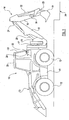
- a material handling vehicle is shown at 10, in this example comprising a back hoe loader.
- the vehicle 10 comprises a structure 11 provided with ground engagable propulsion means, in this example wheels 12.
- the vehicle 10 is provided with a front loader 13 and a material handling device 14 comprising a backhoe.
- the material handling device 14 comprises a first arm part 15 pivotally mounted to the structure 11 via a king post assembly 16 of known type for pivotal movement about horizontal and vertical axes relative to the structure 11, and also for sliding sideways movement on a slide 17 in conventional manner.
- the material handling device 14 further comprises a second arm part 18 which is pivotally mounted on the first arm part 15.
- a material handling implement comprising a bucket 19 is pivotally mounted on the second arm part 18.
- a first actuator 20 comprising a fluid operated ram is mounted between the first arm part 15 and the king post assembly 16.
- a second actuator 21 comprising a fluid operated ram is connected between the first arm part 15 and the second arm part 18.
- a further actuator comprising a fluid operated ram 22 is provided between the second arm part 18 and a link assembly generally shown at 23 connected to the bucket 19.
- the actuators 20, 21, 22 are operated from a control panel shown at 24 provided in an operator's cab 20 of the vehicle 10.
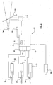
- the vehicle in Figure 1 is provided with an operator display system as generally illustrated at 30 in Figure 2.
- the operator display system 30 has a controller 31 operable to generate an output and a projector 32 which is operable to display the output as an image, in the present example by projecting a display on a rear windscreen 33 of the vehicle 10.
- a controller 31 operable to generate an output
- a projector 32 which is operable to display the output as an image, in the present example by projecting a display on a rear windscreen 33 of the vehicle 10.
- the image appears to be external to the vehicle overlaid on whatever the operator is looking at, as is known from other head up display systems.
- the image appears in this example to be about 2 meters away so that the operator can look at the material handling device 14 and view the image without having to refocus his eyes.
- the system 30 is controllable by the operator through a control 35, for example to vary the display or turn the operator display system 30 on or off.
- the controller 31 is operable to receive input information relating to at least one of the arm 14 and the material handling implement 19, and generate an output in accordance with the display information.
- the vehicle is provided with a plurality of sensing means 36, 37, 38 associated with each of the fluid-operated rams 20, 21, 22.
- the vehicle is also provided with a camera 39 mounted on the second arm part 18 to provide information comprising a video signal to the controller 31.
- the signals from the sensors 36, 37, 38 are passed to decoders 40, 41, 42 to calculate the extension of each fluid-operated ram 20, 21, 22.
- the controller 31 is operable to calculate the position of the material handling implement 19, from the orientation of the arm parts and of the material handling implement 19.
- the controller 31 may for example calculate the location of the tips of the teeth where the material handling implement 19 comprises a bucket.
- An output is then generated in accordance with the calculated position information and an image provided by the projector 32.
- the controller 31 may be provided with a memory shown at 43 on which may be stored target information relating to the desired operation of the material handling device 14.
- the target information may comprise profile information corresponding to the desired dimensions of the excavation.
- An output may be generated by the controller 31 and provided as an image to the operator 34 as desired.
- FIG. 3 to 6 four examples of a view presented to an operator are shown.
- the operator is facing the rear windscreen 33 and is able to view the operation of the material handling device 14 and in particular the material handling implement 19, and view the excavation 44.
- the projector 32 is located to project an image on to the rear windscreen 33 such that an image as shown at 45 is displayed to the operator at an apparent distance of 2 meters.
- the display may be projected on to a prepared area of the windscreen 33 as shown at 46, or if the rear windscreen 33 is suitable may be projected anywhere on the rear windscreen 33 as desired in accordance with the function and current use of the material handling vehicle 10 and material handling device 14.
- the image 45 consists simply of a current position for the material handling implement 19, for example height relative to ground level, and a target depth for the excavation at that extension of the arm 14.
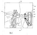
- a more intuitive display is shown at 47 in Figure 4, wherein accordance with the stored profile information a perspective outline of the excavation is shown at 48, with the x and y positions of the material handling implement 19 shown as bars 49, 50 on the trench outline 48. The bars 49 and 50 could of course be combined into a single indicator matching the position of the material handling implement 19 as desired.
- the image 47 is displayed such that it appears to the operator alongside the arm 14 and excavation 44 so that it provides a guide to the excavation 44 without obscuring the operator's view of the arm 14 and material handling implement 19.
- the controller 31 may also be operable to store the calculated position information in the memory 43, such that the controller 31 can generate an output in accordance with past positions of the material handling implement 19. These may be used to, for example, generate a display showing a path of travel of the material handling implement 19 or any other part of the arm 14.
- this stored position information is used to generate an excavation profile by taking the lowest point reached by the material handling implement 19 at each longitudinal position along the trench to provide an excavation profile, thus indicating to an operator what still needs to be done on the excavation 44.
- the image 51 comprises an excavation profile 52 including a desired base 53 of the excavation 44.
- the calculated current excavation profile is shown as the varying surface 54, and the position information showing the current position of the material handling implement 19 is shown at 55.
- the ground level is represented by a line 56. This thus presents the operator a simple and intuitive display of the current position of the material handling implement 19 and where it is in relation to the desired excavation and what remains to be dug out.
- the image from a video camera 39 may also be used to generate an output which is projected onto the rear windscreen 33 as an image 57. This would be useful where, for example, an obstacle comprising a buried pipe 58 is present in the desired excavation 44 and allows the operator to view the obstacle from the cab 25. The operator can switch between different types of image using the control generally shown at 35.
- the position of the fluid actuated rams 20, 21, 22 may be provided by any appropriate sensing apparatus, such as that shown in our co-pending application.
- the decoders 40, 41, 42 may also be provided separately from the controller 31 and may be provided as a single decoder operable to calculate each extension, and possibly, calculate position information as required.
- the display need not be provided on a windscreen 33 of the vehicle 10.
- the display may be provided elsewhere on a suspended or otherwise supported transparent screen viewable by an operator, for example, if the vehicle does not have a windscreen or other window or if the windscreen or other window is inappropriately shaped or located or is otherwise unsuitable,
- a safety helmet 70 to be worn by an operator is shown provided with a screen in the form of a visor 71, and a projector 72 to generate an image on the visor 71 such that the image appears to the operator to be located at an appropriate distance from him, for example, 2 meters as in the previous example.
- the projector 72 may communicate with the controller 71 by any appropriate means as desired, for example by a short range radio frequency connection.
- the invention as described herein thus does not interfere with a normal vision of an operator, provides the operator with an additional choice of views and information.
- the position information thus permits an operator to operate a material handling device with increased accuracy and improved safety.
- the term 'material handling vehicle' may refer to any appropriate type of vehicle such as a telehandler, a loading shovel, a mini excavator, a rotary excavator, a agricultural vehicle such as a tractor or otherwise, and may be tracked/or wheeled, provided with convention skid steering and have any appropriate configuration as desired.
Abstract

Description
- This invention relates to an operator display system for a material handling vehicle, and a material handling vehicle provided with an operator display system.
- In a material handling vehicle, it is conventional for the vehicle to be provided with a multi-part arm where each part of the arm is movable relative either to the vehicle or other parts of the arm by a suitable actuator, conventionally a fluid-operated ram. It is generally the case that each actuator is controlled separately by an operator by operation of an associated valve or control. In general, at least one of the actuators causes pivotal movement of a arm part relative either to the structure of the vehicle itself or to another part of the arm. Consequently, where it is required to move a material handling implement mounted on the arm along a desired path, and in particularly in a generally straight line, a great deal of skill is required on the part of an operator to provide the relative movement between the arm parts and the vehicle such that the material handling implement moves along the desired path. A particular example is in backhoes. Backhoes have at least two arm parts, one of which is pivotally mounted on the vehicle structure and the other arm part which is pivotally mounted on the first arm part. In applications such as digging an excavation, it is desirable to move a material handling implement in the form of a bucket provided on the arm in a straight line towards the vehicle to provide an appropriate flat bottom trench, and a great deal of operator skill is required to cause the requisite pivotal movement of the arm parts to cause the bucket to move along its desired path.
- A source of difficulty for the operator is that the operator has to judge by eye the three-dimensional position of the material handling implement and operate the controls accordingly to move the material handling implement along a desired path. In the example, of a backhoe, the material handling implement may be hidden from the operator's view by the arm, and where the backhoe is being used for an excavation, the base of the trench may also be partly hidden from the driver. It is known to provide a camera on the arm and a television monitor in the cab to enable the operator to, for example, look at the ground underneath the material handling implement to be able to check for obstructions such as buried pipes but this is only of limited assistance in judging the position of the material handling implement and requires the operator to look at a screen and away from the material handling implement itself.
- An aim of the present invention is to reduce or overcome the above problem.
- According to the first aspect of the invention we provide, an operator display system for a material handling vehicle, the material handing vehicle having a material handling device comprising an arm and a material handling implement mounted on the arm, the operator display system being operable to receive input information relating to at least one of the arm and the material handling implement, the operator display system further having a head-up display, the operator display system being operable to generate an output in accordance with the input information and display the output on the head-up display.
- By providing the operator with information relating to the material handling implement position on a head up display, a display giving guidance to the operator may be provided and, by providing the information through a head up display, the operator can still look directly at the material handling implement during operation.
- The input information may comprise position information relating to the position of the material handling implement.
- The input information may comprise information relating to the orientation of the arm and of the material handling implement and the operator display system may be operable to calculate the position of the material handling implement and generate the output accordingly.
- The arm may comprise a plurality of fluid-operated rams and the input information may comprise information relating to the extension of each fluid-operated ram.
- The operator display system may be provided with target information and may be operable to generate the output in accordance with the target information.
- The target information may comprise profile information for an excavation and the operator display system may be operable to generate an output in accordance with the position information and the profile information.
- The operator display system may be operable to store position information and generate an output in accordance with the stored position information.
- The operator display system may be operable to calculate a current excavation profile in accordance with the stored position information and generate an output in accordance with the profile information, the current excavation profile and the position information.
- The input information may comprise a video signal and the operator display system may be operable to generate an output comprising an image.
- The operator display system may comprise a projector operable to generate an image on a window of the vehicle to provide the head up display.
- The operator display system may comprise a projector operable to generate an image on a visor to be worn by an operator to provide the head up display.
- According to a second aspect of the invention we provide a material handling vehicle comprising a material handling device having an arm and a material handling implement provided on the arm, the vehicle further comprising an operator display system and a sensing element associated with at least one of the arm and the material handling implement to generate input information, wherein the operator display system comprises an operator display system according to any one of the preceding claims.
- The arm may comprise a plurality of fluid-operated rams and a sensing element may be associated with each ram to generate input information comprising information relating to the extension of each fluid-operated ram.
- The arm may be provided with a camera to generate input information comprising a video signal and the operator display system may be operable to generate an output comprising an image.
- The invention will now be described by way of example only with reference to the accompanying drawings wherein:
- Figure 1 is a side view of a material handling implement embodying the present invention,
- Figure 2 is a diagrammatic illustration of an operator display system embodying the present invention,
- Figure 3 is an example of the view presented to an operator of the material handling vehicle of Figure 1,
- Figure 4 is a second example of a view presented to an operator,
- Figure 5 is a third example of a view presented to an operator,
- Figure 6 is a fourth example of a view presented to an operator and,
- Figure 7 is a diagrammatic illustration of a hat provided with a display for an operator display system of Figure 2.
-
- Referring now to Figure 1, a material handling vehicle is shown at 10, in this example comprising a back hoe loader. The
vehicle 10 comprises a structure 11 provided with ground engagable propulsion means, in thisexample wheels 12. Thevehicle 10 is provided with afront loader 13 and amaterial handling device 14 comprising a backhoe. Thematerial handling device 14 comprises afirst arm part 15 pivotally mounted to the structure 11 via aking post assembly 16 of known type for pivotal movement about horizontal and vertical axes relative to the structure 11, and also for sliding sideways movement on aslide 17 in conventional manner. Thematerial handling device 14 further comprises asecond arm part 18 which is pivotally mounted on thefirst arm part 15. A material handling implement comprising abucket 19 is pivotally mounted on thesecond arm part 18. - To provide vertical swinging movement, about a horizontal axis of the
first arm part 15, afirst actuator 20 comprising a fluid operated ram is mounted between thefirst arm part 15 and theking post assembly 16. To provide pivotal movement of thesecond arm part 18 relative to thefirst arm part 15, asecond actuator 21 comprising a fluid operated ram is connected between thefirst arm part 15 and thesecond arm part 18. To provide for pivotal movement of thebucket 19 relative to thesecond arm part 18, a further actuator comprising a fluid operatedram 22 is provided between thesecond arm part 18 and a link assembly generally shown at 23 connected to thebucket 19. Theactuators cab 20 of thevehicle 10. - The vehicle in Figure 1 is provided with an operator display system as generally illustrated at 30 in Figure 2. The
operator display system 30 has acontroller 31 operable to generate an output and aprojector 32 which is operable to display the output as an image, in the present example by projecting a display on arear windscreen 33 of thevehicle 10. When viewed by an operator as diagrammatically illustrated at 34, the image appears to be external to the vehicle overlaid on whatever the operator is looking at, as is known from other head up display systems. The image appears in this example to be about 2 meters away so that the operator can look at thematerial handling device 14 and view the image without having to refocus his eyes. Thesystem 30 is controllable by the operator through acontrol 35, for example to vary the display or turn theoperator display system 30 on or off. - The
controller 31 is operable to receive input information relating to at least one of thearm 14 and the material handling implement 19, and generate an output in accordance with the display information. In the present example, the vehicle is provided with a plurality of sensing means 36, 37, 38 associated with each of the fluid-operatedrams camera 39 mounted on thesecond arm part 18 to provide information comprising a video signal to thecontroller 31. - In the present example, the signals from the
sensors decoders ram controller 31 is operable to calculate the position of the material handling implement 19, from the orientation of the arm parts and of the material handling implement 19. Thecontroller 31 may for example calculate the location of the tips of the teeth where the material handling implement 19 comprises a bucket. An output is then generated in accordance with the calculated position information and an image provided by theprojector 32. - It will be apparent that the position information may be made available to an operator of the
vehicle 10 in any appropriate manner which may be desirable. In particular, thecontroller 31 may be provided with a memory shown at 43 on which may be stored target information relating to the desired operation of thematerial handling device 14. In the present example, where thematerial handling device 14 is a backhoe to be used to carry out an excavation such as digging a trench, the target information may comprise profile information corresponding to the desired dimensions of the excavation. An output may be generated by thecontroller 31 and provided as an image to theoperator 34 as desired. - Referring now to Figures 3 to 6, four examples of a view presented to an operator are shown. The operator is facing the
rear windscreen 33 and is able to view the operation of thematerial handling device 14 and in particular the material handling implement 19, and view theexcavation 44. Theprojector 32 is located to project an image on to therear windscreen 33 such that an image as shown at 45 is displayed to the operator at an apparent distance of 2 meters. The display may be projected on to a prepared area of thewindscreen 33 as shown at 46, or if therear windscreen 33 is suitable may be projected anywhere on therear windscreen 33 as desired in accordance with the function and current use of thematerial handling vehicle 10 andmaterial handling device 14. - In the example of Figure 3, the image 45 consists simply of a current position for the material handling implement 19, for example height relative to ground level, and a target depth for the excavation at that extension of the
arm 14. A more intuitive display is shown at 47 in Figure 4, wherein accordance with the stored profile information a perspective outline of the excavation is shown at 48, with the x and y positions of the material handling implement 19 shown asbars trench outline 48. Thebars image 47 is displayed such that it appears to the operator alongside thearm 14 andexcavation 44 so that it provides a guide to theexcavation 44 without obscuring the operator's view of thearm 14 and material handling implement 19. - The
controller 31 may also be operable to store the calculated position information in thememory 43, such that thecontroller 31 can generate an output in accordance with past positions of the material handling implement 19. These may be used to, for example, generate a display showing a path of travel of the material handling implement 19 or any other part of thearm 14. In the example of Figure 5, this stored position information is used to generate an excavation profile by taking the lowest point reached by the material handling implement 19 at each longitudinal position along the trench to provide an excavation profile, thus indicating to an operator what still needs to be done on theexcavation 44. Thus, in Figure 5 theimage 51 comprises anexcavation profile 52 including a desiredbase 53 of theexcavation 44. The calculated current excavation profile is shown as the varyingsurface 54, and the position information showing the current position of the material handling implement 19 is shown at 55. In this example, the ground level is represented by aline 56. This thus presents the operator a simple and intuitive display of the current position of the material handling implement 19 and where it is in relation to the desired excavation and what remains to be dug out. - As illustrated in Figure 6, the image from a
video camera 39 may also be used to generate an output which is projected onto therear windscreen 33 as animage 57. This would be useful where, for example, an obstacle comprising a buriedpipe 58 is present in the desiredexcavation 44 and allows the operator to view the obstacle from thecab 25. The operator can switch between different types of image using the control generally shown at 35. - The position of the fluid actuated
rams decoders controller 31 and may be provided as a single decoder operable to calculate each extension, and possibly, calculate position information as required. - It is envisaged that the display need not be provided on a
windscreen 33 of thevehicle 10. The display may be provided elsewhere on a suspended or otherwise supported transparent screen viewable by an operator, for example, if the vehicle does not have a windscreen or other window or if the windscreen or other window is inappropriately shaped or located or is otherwise unsuitable, As a further example, at Figure 7, asafety helmet 70 to be worn by an operator is shown provided with a screen in the form of avisor 71, and aprojector 72 to generate an image on thevisor 71 such that the image appears to the operator to be located at an appropriate distance from him, for example, 2 meters as in the previous example. Theprojector 72 may communicate with thecontroller 71 by any appropriate means as desired, for example by a short range radio frequency connection. - The invention as described herein thus does not interfere with a normal vision of an operator, provides the operator with an additional choice of views and information. The position information thus permits an operator to operate a material handling device with increased accuracy and improved safety.
- Although the material handling vehicle shown herein, is a backhoe, the term 'material handling vehicle' may refer to any appropriate type of vehicle such as a telehandler, a loading shovel, a mini excavator, a rotary excavator, a agricultural vehicle such as a tractor or otherwise, and may be tracked/or wheeled, provided with convention skid steering and have any appropriate configuration as desired.
- In the present specification "comprise" means "includes or consists of" and "comprising" means "including or consisting of".
- The features disclosed in the foregoing description, or the following claims, or the accompanying drawings, expressed in their specific forms or in terms of a means for performing the disclosed function, or a method or process for attaining the disclosed result, as appropriate, may, separately, or in any combination of such features, be utilised for realising the invention in diverse forms thereof.
Claims (13)
the operator display system being operable to receive input information comprising information relating to the orientation of the arm and of the material handling implement and calculate the position of the material handling implement,
the operator display system further having a head-up display,
the operator display system being operable to generate an output in accordance with the input information and display the output on the head-up display.
the vehicle further comprising an operator display system and a sensing element associated with at least one of the arm and the material handling implement to generate input information,
wherein the operator display system comprises an operator display system according to any one of the preceding claims.
Applications Claiming Priority (2)
| Application Number | Priority Date | Filing Date | Title |
|---|---|---|---|
| GB0410415 | 2004-05-11 | ||
| GBGB0410415.4A GB0410415D0 (en) | 2004-05-11 | 2004-05-11 | Operator display system |
Publications (3)
| Publication Number | Publication Date |
|---|---|
| EP1596013A2 true EP1596013A2 (en) | 2005-11-16 |
| EP1596013A3 EP1596013A3 (en) | 2006-10-04 |
| EP1596013B1 EP1596013B1 (en) | 2013-09-11 |
Family
ID=32526771
Family Applications (1)
| Application Number | Title | Priority Date | Filing Date |
|---|---|---|---|
| EP05010203.7A Active EP1596013B1 (en) | 2004-05-11 | 2005-05-11 | Operator display system |
Country Status (3)
| Country | Link |
|---|---|
| US (1) | US7606648B2 (en) |
| EP (1) | EP1596013B1 (en) |
| GB (2) | GB0410415D0 (en) |
Cited By (2)
| Publication number | Priority date | Publication date | Assignee | Title |
|---|---|---|---|---|
| WO2015200440A1 (en) * | 2014-06-27 | 2015-12-30 | Topcon Positioning Systems, Inc. | Method and apparatus for providing guidance to an operator of construction machines |
| EP3934241A4 (en) * | 2019-02-28 | 2022-04-20 | Sumitomo Heavy Industries, Ltd. | Display device, shovel, information processing device |
Families Citing this family (27)
| Publication number | Priority date | Publication date | Assignee | Title |
|---|---|---|---|---|
| GB0410415D0 (en) * | 2004-05-11 | 2004-06-16 | Bamford Excavators Ltd | Operator display system |
| US20070205875A1 (en) * | 2006-03-03 | 2007-09-06 | De Haan Ido G | Auxiliary device with projection display information alert |
| WO2011067456A1 (en) * | 2009-12-03 | 2011-06-09 | John Deere Forestry Oy | A method and a system for a work machine with a boom |
| US8342597B2 (en) * | 2010-08-11 | 2013-01-01 | Komatsu Ltd. | Work vehicle equipped with rear monitoring camera apparatus |
| US8858124B2 (en) | 2010-10-12 | 2014-10-14 | BOH Bros. Construction Co., LLC | Excavation system |
| CL2012000933A1 (en) * | 2011-04-14 | 2014-07-25 | Harnischfeger Tech Inc | A method and a cable shovel for the generation of an ideal path, comprises: an oscillation engine, a hoisting engine, a feed motor, a bucket for digging and emptying materials and, positioning the shovel by means of the operation of the lifting motor, feed motor and oscillation engine and; a controller that includes an ideal path generator module. |
| JP5848451B1 (en) * | 2014-06-02 | 2016-01-27 | 株式会社小松製作所 | Construction machine control system, construction machine, and construction machine control method |
| US10503249B2 (en) * | 2014-07-03 | 2019-12-10 | Topcon Positioning Systems, Inc. | Method and apparatus for construction machine visualization |
| JP6777375B2 (en) * | 2015-03-05 | 2020-10-28 | 株式会社小松製作所 | Work machine image display system, work machine remote control system and work machine |
| JP6540948B2 (en) * | 2015-03-27 | 2019-07-10 | 株式会社富士通ゼネラル | Camera system |
| US9783112B2 (en) | 2015-10-27 | 2017-10-10 | Cnh Industrial America Llc | Rear windshield implement status heads-up display |
| JP6844216B2 (en) * | 2015-11-25 | 2021-03-17 | 株式会社リコー | Visualization system |
| JP6620011B2 (en) * | 2015-12-25 | 2019-12-11 | 株式会社小松製作所 | Work vehicle and display control method |
| JP6626710B2 (en) * | 2015-12-25 | 2019-12-25 | 株式会社小松製作所 | Work vehicle and work vehicle control method |
| JP6813268B2 (en) * | 2016-02-16 | 2021-01-13 | 株式会社小松製作所 | Work vehicle |
| EP3438355A4 (en) * | 2016-03-30 | 2019-03-20 | Sumitomo (S.H.I.) Construction Machinery Co., Ltd. | Shovel |
| AU2017318911B2 (en) * | 2016-08-31 | 2020-07-02 | Komatsu Ltd. | Image display system of work machine, remote operation system of work machine, work machine, and method for displaying image of work machine |
| CN110099818A (en) * | 2016-12-21 | 2019-08-06 | 富士胶片株式会社 | Projection display device, the control method of projection display device, the control program of projection display device |
| US10907326B2 (en) | 2017-08-11 | 2021-02-02 | Deere & Company | Vision system for monitoring a work tool of a work vehicle |
| US11255072B1 (en) | 2017-12-15 | 2022-02-22 | Michael A. Fesi | Method and apparatus for excavating a soil containing mass |
| JP7119371B2 (en) * | 2017-12-27 | 2022-08-17 | コベルコ建機株式会社 | Crane and information display method |
| JP7122863B2 (en) * | 2018-05-14 | 2022-08-22 | 株式会社Ihiエアロスペース | Image display device, image display method and remote control system |
| JP6918867B2 (en) * | 2018-06-20 | 2021-08-11 | 住友建機株式会社 | Excavator, excavator display method and excavator display device |
| JP7128497B2 (en) * | 2020-09-29 | 2022-08-31 | 株式会社小松製作所 | Image display system for working machines |
| JP7333551B2 (en) * | 2020-09-29 | 2023-08-25 | 株式会社小松製作所 | Image display system for working machines |
| JP7131779B2 (en) * | 2020-10-08 | 2022-09-06 | 株式会社小松製作所 | Image display system for working machine, remote control system for working machine, working machine, and image display method for working machine |
| DE102021109330A1 (en) * | 2021-04-14 | 2022-10-20 | Deere & Company | Augmented reality perception method for an agricultural utility vehicle |
Citations (3)
| Publication number | Priority date | Publication date | Assignee | Title |
|---|---|---|---|---|
| US5701793A (en) * | 1996-06-24 | 1997-12-30 | Catepillar Inc. | Method and apparatus for controlling an implement of a work machine |
| US20020077737A1 (en) * | 2000-12-16 | 2002-06-20 | Kalafut James J. | Method and appartaus for providing a display of a work machine at a work site |
| US20030001751A1 (en) * | 2000-11-17 | 2003-01-02 | Hiroshi Ogura | Display device and display controller of construction machinery |
Family Cites Families (37)
| Publication number | Priority date | Publication date | Assignee | Title |
|---|---|---|---|---|
| US7415126B2 (en) * | 1992-05-05 | 2008-08-19 | Automotive Technologies International Inc. | Occupant sensing system |
| DE8337558U1 (en) | 1983-12-29 | 1984-05-17 | Heß, Wilhelm, 5000 Köln | EXCAVATOR |
| US4949263A (en) * | 1987-06-01 | 1990-08-14 | Alert-O-Brake Systems Inc. | Load handling vehicle monitoring system |
| US4832287A (en) * | 1987-07-22 | 1989-05-23 | Bertil Werjefelt | Operator station emergency visual assurance method and apparatus |
| US5072218A (en) * | 1988-02-24 | 1991-12-10 | Spero Robert E | Contact-analog headup display method and apparatus |
| JPH01312129A (en) | 1988-06-13 | 1989-12-15 | Komatsu Ltd | Monitoring device for arm-type work machine |
| DE68923946T2 (en) * | 1988-12-28 | 1996-01-11 | Nippon Yusoki Co Ltd | Control system for industrial trucks. |
| US5416616A (en) * | 1990-04-06 | 1995-05-16 | University Of Southern California | Incoherent/coherent readout of double angularly multiplexed volume holographic optical elements |
| JPH04308814A (en) * | 1991-04-06 | 1992-10-30 | Ricoh Co Ltd | Liquid crystal display device |
| JPH06156119A (en) | 1992-11-18 | 1994-06-03 | Kansei Corp | Head-up display device for construction machine |
| US5673963A (en) | 1993-03-18 | 1997-10-07 | Pietzsch Automatisierungstechnik Gmbh | Cab for accomodating the operator of a vehicle or machine |
| US5455591A (en) * | 1994-06-30 | 1995-10-03 | Hughes Aircraft Company | Precision high speed perspective transformation from range-azimuth format to elevation-azimuth format |
| JP2875954B2 (en) | 1994-09-02 | 1999-03-31 | 新キャタピラー三菱株式会社 | Camera automatic tracking controller for construction machinery |
| JPH08319640A (en) | 1995-05-25 | 1996-12-03 | Sumitomo Constr Mach Co Ltd | Construction equipment for deep excavation work |
| JPH09200650A (en) | 1996-01-17 | 1997-07-31 | Nippon Steel Corp | Video display method and its device |
| US5811055A (en) * | 1996-02-06 | 1998-09-22 | Geiger; Michael B. | Torch mounted gas scavaging system for manual and robotic welding and cutting torches |
| US6014117A (en) * | 1997-07-03 | 2000-01-11 | Monterey Technologies, Inc. | Ambient vision display apparatus and method |
| US6034653A (en) * | 1997-08-01 | 2000-03-07 | Colorado Microdisplay, Inc. | Head-set display device |
| US6039141A (en) | 1998-02-23 | 2000-03-21 | Case Corporation | Moving operator and display unit |
| US6233748B1 (en) * | 1998-07-31 | 2001-05-22 | Integrated Medical Systems, Inc. | Environmental protection system |
| US6208933B1 (en) * | 1998-12-04 | 2001-03-27 | Northrop Grumman Corporation | Cartographic overlay on sensor video |
| US6371232B1 (en) * | 1999-04-30 | 2002-04-16 | Franklin Equipment Co., Inc. | Tractor cab providing under-cab component access |
| WO2001064481A2 (en) * | 2000-03-02 | 2001-09-07 | Donnelly Corporation | Video mirror systems incorporating an accessory module |
| DE10014437A1 (en) | 2000-03-16 | 2001-09-27 | Mannesmann Ag | Alerting method for a crane driver that is making or about to make a dangerous movement in which an optical alert is arranged so that it is within the driver's field of vision, e.g. in the crane windshield |
| US6536553B1 (en) * | 2000-04-25 | 2003-03-25 | The United States Of America As Represented By The Secretary Of The Army | Method and apparatus using acoustic sensor for sub-surface object detection and visualization |
| JP2001341684A (en) * | 2000-05-30 | 2001-12-11 | Moric Co Ltd | Controller for straddle type vehicle |
| JP2003044704A (en) * | 2001-07-31 | 2003-02-14 | Honda Motor Co Ltd | Method for providing service |
| JP2004185190A (en) * | 2002-12-02 | 2004-07-02 | Hitachi Constr Mach Co Ltd | Information processing system of construction machine and information processing method of construction machine |
| DE10339050A1 (en) * | 2003-08-25 | 2005-03-31 | Siemens Ag | Portrayal of information in a motor vehicle that has two or more information displays, whereby information is output to a given display on the basis of evaluation of presentation criteria |
| WO2005094222A2 (en) * | 2004-03-05 | 2005-10-13 | United States Postal Service | Ergonomically designed mail transport and delivery vehicle |
| GB0410415D0 (en) * | 2004-05-11 | 2004-06-16 | Bamford Excavators Ltd | Operator display system |
| US7626569B2 (en) * | 2004-10-25 | 2009-12-01 | Graphics Properties Holdings, Inc. | Movable audio/video communication interface system |
| US7333922B2 (en) * | 2005-03-30 | 2008-02-19 | Caterpillar Inc. | System and method of monitoring machine performance |
| US7474204B2 (en) * | 2005-06-06 | 2009-01-06 | Joneso Design & Consulting, Inc. | Vehicle information/control system |
| JP4452243B2 (en) * | 2006-01-06 | 2010-04-21 | 矢崎総業株式会社 | Head-up display combiner storage method and head-up display combiner storage device |
| US20080007617A1 (en) * | 2006-05-11 | 2008-01-10 | Ritchey Kurtis J | Volumetric panoramic sensor systems |
| US7648413B2 (en) * | 2007-03-01 | 2010-01-19 | Cnh America Llc | Combine harvester power management control |
-
2004
- 2004-05-11 GB GBGB0410415.4A patent/GB0410415D0/en not_active Ceased
-
2005
- 2005-05-10 US US11/125,936 patent/US7606648B2/en not_active Expired - Fee Related
- 2005-05-11 EP EP05010203.7A patent/EP1596013B1/en active Active
- 2005-05-11 GB GB0509562A patent/GB2414010B/en active Active
Patent Citations (3)
| Publication number | Priority date | Publication date | Assignee | Title |
|---|---|---|---|---|
| US5701793A (en) * | 1996-06-24 | 1997-12-30 | Catepillar Inc. | Method and apparatus for controlling an implement of a work machine |
| US20030001751A1 (en) * | 2000-11-17 | 2003-01-02 | Hiroshi Ogura | Display device and display controller of construction machinery |
| US20020077737A1 (en) * | 2000-12-16 | 2002-06-20 | Kalafut James J. | Method and appartaus for providing a display of a work machine at a work site |
Non-Patent Citations (1)
| Title |
|---|
| PATENT ABSTRACTS OF JAPAN vol. 017, no. 129 (P-1503), 18 March 1993 (1993-03-18) & JP 04 308814 A (RICOH CO LTD), 30 October 1992 (1992-10-30) * |
Cited By (4)
| Publication number | Priority date | Publication date | Assignee | Title |
|---|---|---|---|---|
| WO2015200440A1 (en) * | 2014-06-27 | 2015-12-30 | Topcon Positioning Systems, Inc. | Method and apparatus for providing guidance to an operator of construction machines |
| US9752303B2 (en) | 2014-06-27 | 2017-09-05 | Topcon Positioning Systems, Inc. | Method and apparatus for implementing operational practices for construction machines |
| EP3934241A4 (en) * | 2019-02-28 | 2022-04-20 | Sumitomo Heavy Industries, Ltd. | Display device, shovel, information processing device |
| US11939747B2 (en) | 2019-02-28 | 2024-03-26 | Sumitomo Heavy Industries, Ltd. | Display device, shovel, information processing apparatus |
Also Published As
| Publication number | Publication date |
|---|---|
| US7606648B2 (en) | 2009-10-20 |
| GB0410415D0 (en) | 2004-06-16 |
| EP1596013B1 (en) | 2013-09-11 |
| EP1596013A3 (en) | 2006-10-04 |
| GB2414010A (en) | 2005-11-16 |
| GB2414010B (en) | 2008-03-05 |
| GB0509562D0 (en) | 2005-06-15 |
| US20050256607A1 (en) | 2005-11-17 |
Similar Documents
| Publication | Publication Date | Title |
|---|---|---|
| EP1596013B1 (en) | Operator display system | |
| US8918246B2 (en) | Augmented reality implement control | |
| KR101815268B1 (en) | Construction machinery display system and control method for same | |
| US10421400B2 (en) | Surroundings monitoring system for work vehicle, work vehicle, and surroundings monitoring method for work vehicle | |
| US10036141B2 (en) | Control system for work vehicle, control method and work vehicle | |
| JP5269026B2 (en) | Work machine ambient monitoring device | |
| EP3174291A1 (en) | Surroundings display device for turning operation machine | |
| EP2717570A1 (en) | Device for monitoring area around working machine | |
| WO2016158265A1 (en) | Working machine | |
| CN108368694B (en) | Work vehicle and display control method | |
| AU2012257053A1 (en) | Device for monitoring area around working machine | |
| JP6454383B2 (en) | Construction machine display system and control method thereof | |
| US10942351B2 (en) | Work vehicle and display control method | |
| EP3739131B1 (en) | Construction machine | |
| US10954655B2 (en) | Work vehicle and method for controlling work vehicle | |
| JP6823036B2 (en) | Display system for construction machinery and its control method | |
| US20210246635A1 (en) | Display system for work machine | |
| US20240026658A1 (en) | Target path changing system for attachment | |
| WO2022209176A1 (en) | Travel system for work machine and method for controlling work machine | |
| JP7168697B2 (en) | DISPLAY SYSTEM FOR CONSTRUCTION MACHINE AND CONTROL METHOD THEREOF | |
| WO2023157707A1 (en) | Display control device and remote operation device | |
| US11661722B2 (en) | System and method for customized visualization of the surroundings of self-propelled work vehicles | |
| JP7428588B2 (en) | Video display system for construction vehicles | |
| EP4043285A1 (en) | Periphery monitoring device for working machine | |
| US20230339402A1 (en) | Selectively utilizing multiple imaging devices to maintain a view of an area of interest proximate a work vehicle |
Legal Events
| Date | Code | Title | Description |
|---|---|---|---|
| PUAI | Public reference made under article 153(3) epc to a published international application that has entered the european phase |
Free format text: ORIGINAL CODE: 0009012 |
|
| AK | Designated contracting states |
Kind code of ref document: A2 Designated state(s): AT BE BG CH CY CZ DE DK EE ES FI FR GB GR HU IE IS IT LI LT LU MC NL PL PT RO SE SI SK TR |
|
| AX | Request for extension of the european patent |
Extension state: AL BA HR LV MK YU |
|
| PUAL | Search report despatched |
Free format text: ORIGINAL CODE: 0009013 |
|
| AK | Designated contracting states |
Kind code of ref document: A3 Designated state(s): AT BE BG CH CY CZ DE DK EE ES FI FR GB GR HU IE IS IT LI LT LU MC NL PL PT RO SE SI SK TR |
|
| AX | Request for extension of the european patent |
Extension state: AL BA HR LV MK YU |
|
| 17P | Request for examination filed |
Effective date: 20070302 |
|
| AKX | Designation fees paid |
Designated state(s): AT BE BG CH CY CZ DE DK EE ES FI FR GB GR HU IE IS IT LI LT LU MC NL PL PT RO SE SI SK TR |
|
| 17Q | First examination report despatched |
Effective date: 20071102 |
|
| GRAP | Despatch of communication of intention to grant a patent |
Free format text: ORIGINAL CODE: EPIDOSNIGR1 |
|
| GRAS | Grant fee paid |
Free format text: ORIGINAL CODE: EPIDOSNIGR3 |
|
| GRAP | Despatch of communication of intention to grant a patent |
Free format text: ORIGINAL CODE: EPIDOSNIGR1 |
|
| INTG | Intention to grant announced |
Effective date: 20130619 |
|
| GRAA | (expected) grant |
Free format text: ORIGINAL CODE: 0009210 |
|
| AK | Designated contracting states |
Kind code of ref document: B1 Designated state(s): AT BE BG CH CY CZ DE DK EE ES FI FR GB GR HU IE IS IT LI LT LU MC NL PL PT RO SE SI SK TR |
|
| REG | Reference to a national code |
Ref country code: GB Ref legal event code: FG4D |
|
| REG | Reference to a national code |
Ref country code: CH Ref legal event code: EP |
|
| REG | Reference to a national code |
Ref country code: AT Ref legal event code: REF Ref document number: 631734 Country of ref document: AT Kind code of ref document: T Effective date: 20130915 |
|
| REG | Reference to a national code |
Ref country code: IE Ref legal event code: FG4D |
|
| REG | Reference to a national code |
Ref country code: DE Ref legal event code: R096 Ref document number: 602005041170 Country of ref document: DE Effective date: 20131107 |
|
| PG25 | Lapsed in a contracting state [announced via postgrant information from national office to epo] |
Ref country code: SE Free format text: LAPSE BECAUSE OF FAILURE TO SUBMIT A TRANSLATION OF THE DESCRIPTION OR TO PAY THE FEE WITHIN THE PRESCRIBED TIME-LIMIT Effective date: 20130911 Ref country code: LT Free format text: LAPSE BECAUSE OF FAILURE TO SUBMIT A TRANSLATION OF THE DESCRIPTION OR TO PAY THE FEE WITHIN THE PRESCRIBED TIME-LIMIT Effective date: 20130911 Ref country code: CY Free format text: LAPSE BECAUSE OF FAILURE TO SUBMIT A TRANSLATION OF THE DESCRIPTION OR TO PAY THE FEE WITHIN THE PRESCRIBED TIME-LIMIT Effective date: 20130619 |
|
| REG | Reference to a national code |
Ref country code: NL Ref legal event code: VDEP Effective date: 20130911 |
|
| REG | Reference to a national code |
Ref country code: AT Ref legal event code: MK05 Ref document number: 631734 Country of ref document: AT Kind code of ref document: T Effective date: 20130911 |
|
| REG | Reference to a national code |
Ref country code: LT Ref legal event code: MG4D |
|
| PG25 | Lapsed in a contracting state [announced via postgrant information from national office to epo] |
Ref country code: ES Free format text: LAPSE BECAUSE OF FAILURE TO SUBMIT A TRANSLATION OF THE DESCRIPTION OR TO PAY THE FEE WITHIN THE PRESCRIBED TIME-LIMIT Effective date: 20130911 Ref country code: FI Free format text: LAPSE BECAUSE OF FAILURE TO SUBMIT A TRANSLATION OF THE DESCRIPTION OR TO PAY THE FEE WITHIN THE PRESCRIBED TIME-LIMIT Effective date: 20130911 Ref country code: GR Free format text: LAPSE BECAUSE OF FAILURE TO SUBMIT A TRANSLATION OF THE DESCRIPTION OR TO PAY THE FEE WITHIN THE PRESCRIBED TIME-LIMIT Effective date: 20131212 Ref country code: SI Free format text: LAPSE BECAUSE OF FAILURE TO SUBMIT A TRANSLATION OF THE DESCRIPTION OR TO PAY THE FEE WITHIN THE PRESCRIBED TIME-LIMIT Effective date: 20130911 |
|
| PG25 | Lapsed in a contracting state [announced via postgrant information from national office to epo] |
Ref country code: CY Free format text: LAPSE BECAUSE OF FAILURE TO SUBMIT A TRANSLATION OF THE DESCRIPTION OR TO PAY THE FEE WITHIN THE PRESCRIBED TIME-LIMIT Effective date: 20130911 Ref country code: BE Free format text: LAPSE BECAUSE OF FAILURE TO SUBMIT A TRANSLATION OF THE DESCRIPTION OR TO PAY THE FEE WITHIN THE PRESCRIBED TIME-LIMIT Effective date: 20130911 |
|
| PG25 | Lapsed in a contracting state [announced via postgrant information from national office to epo] |
Ref country code: EE Free format text: LAPSE BECAUSE OF FAILURE TO SUBMIT A TRANSLATION OF THE DESCRIPTION OR TO PAY THE FEE WITHIN THE PRESCRIBED TIME-LIMIT Effective date: 20130911 Ref country code: CZ Free format text: LAPSE BECAUSE OF FAILURE TO SUBMIT A TRANSLATION OF THE DESCRIPTION OR TO PAY THE FEE WITHIN THE PRESCRIBED TIME-LIMIT Effective date: 20130911 Ref country code: NL Free format text: LAPSE BECAUSE OF FAILURE TO SUBMIT A TRANSLATION OF THE DESCRIPTION OR TO PAY THE FEE WITHIN THE PRESCRIBED TIME-LIMIT Effective date: 20130911 Ref country code: RO Free format text: LAPSE BECAUSE OF FAILURE TO SUBMIT A TRANSLATION OF THE DESCRIPTION OR TO PAY THE FEE WITHIN THE PRESCRIBED TIME-LIMIT Effective date: 20130911 Ref country code: IS Free format text: LAPSE BECAUSE OF FAILURE TO SUBMIT A TRANSLATION OF THE DESCRIPTION OR TO PAY THE FEE WITHIN THE PRESCRIBED TIME-LIMIT Effective date: 20140111 Ref country code: SK Free format text: LAPSE BECAUSE OF FAILURE TO SUBMIT A TRANSLATION OF THE DESCRIPTION OR TO PAY THE FEE WITHIN THE PRESCRIBED TIME-LIMIT Effective date: 20130911 |
|
| PG25 | Lapsed in a contracting state [announced via postgrant information from national office to epo] |
Ref country code: AT Free format text: LAPSE BECAUSE OF FAILURE TO SUBMIT A TRANSLATION OF THE DESCRIPTION OR TO PAY THE FEE WITHIN THE PRESCRIBED TIME-LIMIT Effective date: 20130911 Ref country code: PL Free format text: LAPSE BECAUSE OF FAILURE TO SUBMIT A TRANSLATION OF THE DESCRIPTION OR TO PAY THE FEE WITHIN THE PRESCRIBED TIME-LIMIT Effective date: 20130911 |
|
| REG | Reference to a national code |
Ref country code: DE Ref legal event code: R097 Ref document number: 602005041170 Country of ref document: DE |
|
| PG25 | Lapsed in a contracting state [announced via postgrant information from national office to epo] |
Ref country code: PT Free format text: LAPSE BECAUSE OF FAILURE TO SUBMIT A TRANSLATION OF THE DESCRIPTION OR TO PAY THE FEE WITHIN THE PRESCRIBED TIME-LIMIT Effective date: 20140113 |
|
| PLBE | No opposition filed within time limit |
Free format text: ORIGINAL CODE: 0009261 |
|
| STAA | Information on the status of an ep patent application or granted ep patent |
Free format text: STATUS: NO OPPOSITION FILED WITHIN TIME LIMIT |
|
| 26N | No opposition filed |
Effective date: 20140612 |
|
| PG25 | Lapsed in a contracting state [announced via postgrant information from national office to epo] |
Ref country code: IT Free format text: LAPSE BECAUSE OF FAILURE TO SUBMIT A TRANSLATION OF THE DESCRIPTION OR TO PAY THE FEE WITHIN THE PRESCRIBED TIME-LIMIT Effective date: 20130911 |
|
| REG | Reference to a national code |
Ref country code: DE Ref legal event code: R097 Ref document number: 602005041170 Country of ref document: DE Effective date: 20140612 |
|
| PG25 | Lapsed in a contracting state [announced via postgrant information from national office to epo] |
Ref country code: DK Free format text: LAPSE BECAUSE OF FAILURE TO SUBMIT A TRANSLATION OF THE DESCRIPTION OR TO PAY THE FEE WITHIN THE PRESCRIBED TIME-LIMIT Effective date: 20130911 |
|
| PG25 | Lapsed in a contracting state [announced via postgrant information from national office to epo] |
Ref country code: LU Free format text: LAPSE BECAUSE OF FAILURE TO SUBMIT A TRANSLATION OF THE DESCRIPTION OR TO PAY THE FEE WITHIN THE PRESCRIBED TIME-LIMIT Effective date: 20140511 |
|
| REG | Reference to a national code |
Ref country code: CH Ref legal event code: PL |
|
| PG25 | Lapsed in a contracting state [announced via postgrant information from national office to epo] |
Ref country code: CH Free format text: LAPSE BECAUSE OF NON-PAYMENT OF DUE FEES Effective date: 20140531 Ref country code: LI Free format text: LAPSE BECAUSE OF NON-PAYMENT OF DUE FEES Effective date: 20140531 Ref country code: MC Free format text: LAPSE BECAUSE OF FAILURE TO SUBMIT A TRANSLATION OF THE DESCRIPTION OR TO PAY THE FEE WITHIN THE PRESCRIBED TIME-LIMIT Effective date: 20130911 |
|
| REG | Reference to a national code |
Ref country code: IE Ref legal event code: MM4A |
|
| PG25 | Lapsed in a contracting state [announced via postgrant information from national office to epo] |
Ref country code: IE Free format text: LAPSE BECAUSE OF NON-PAYMENT OF DUE FEES Effective date: 20140511 |
|
| REG | Reference to a national code |
Ref country code: FR Ref legal event code: PLFP Year of fee payment: 12 |
|
| PG25 | Lapsed in a contracting state [announced via postgrant information from national office to epo] |
Ref country code: BG Free format text: LAPSE BECAUSE OF FAILURE TO SUBMIT A TRANSLATION OF THE DESCRIPTION OR TO PAY THE FEE WITHIN THE PRESCRIBED TIME-LIMIT Effective date: 20130911 |
|
| PG25 | Lapsed in a contracting state [announced via postgrant information from national office to epo] |
Ref country code: TR Free format text: LAPSE BECAUSE OF FAILURE TO SUBMIT A TRANSLATION OF THE DESCRIPTION OR TO PAY THE FEE WITHIN THE PRESCRIBED TIME-LIMIT Effective date: 20130911 Ref country code: HU Free format text: LAPSE BECAUSE OF FAILURE TO SUBMIT A TRANSLATION OF THE DESCRIPTION OR TO PAY THE FEE WITHIN THE PRESCRIBED TIME-LIMIT; INVALID AB INITIO Effective date: 20050511 |
|
| REG | Reference to a national code |
Ref country code: FR Ref legal event code: PLFP Year of fee payment: 13 |
|
| REG | Reference to a national code |
Ref country code: FR Ref legal event code: PLFP Year of fee payment: 14 |
|
| PGFP | Annual fee paid to national office [announced via postgrant information from national office to epo] |
Ref country code: DE Payment date: 20190521 Year of fee payment: 15 |
|
| PGFP | Annual fee paid to national office [announced via postgrant information from national office to epo] |
Ref country code: FR Payment date: 20190523 Year of fee payment: 15 |
|
| REG | Reference to a national code |
Ref country code: DE Ref legal event code: R119 Ref document number: 602005041170 Country of ref document: DE |
|
| PG25 | Lapsed in a contracting state [announced via postgrant information from national office to epo] |
Ref country code: FR Free format text: LAPSE BECAUSE OF NON-PAYMENT OF DUE FEES Effective date: 20200531 |
|
| PG25 | Lapsed in a contracting state [announced via postgrant information from national office to epo] |
Ref country code: DE Free format text: LAPSE BECAUSE OF NON-PAYMENT OF DUE FEES Effective date: 20201201 |
|
| P01 | Opt-out of the competence of the unified patent court (upc) registered |
Effective date: 20230525 |
|
| PGFP | Annual fee paid to national office [announced via postgrant information from national office to epo] |
Ref country code: GB Payment date: 20230516 Year of fee payment: 19 |