EP1594404B1 - Ultrasonic imaging device and system - Google Patents
Ultrasonic imaging device and system Download PDFInfo
- Publication number
- EP1594404B1 EP1594404B1 EP04704866.5A EP04704866A EP1594404B1 EP 1594404 B1 EP1594404 B1 EP 1594404B1 EP 04704866 A EP04704866 A EP 04704866A EP 1594404 B1 EP1594404 B1 EP 1594404B1
- Authority
- EP
- European Patent Office
- Prior art keywords
- array
- probe
- circuitry
- combination
- transducer elements
- Prior art date
- Legal status (The legal status is an assumption and is not a legal conclusion. Google has not performed a legal analysis and makes no representation as to the accuracy of the status listed.)
- Expired - Lifetime
Links
- 238000003384 imaging method Methods 0.000 title claims description 15
- 239000000523 sample Substances 0.000 claims description 62
- 238000003491 array Methods 0.000 claims description 18
- 230000005284 excitation Effects 0.000 claims 4
- 210000002307 prostate Anatomy 0.000 description 19
- 238000002725 brachytherapy Methods 0.000 description 8
- 238000000034 method Methods 0.000 description 8
- 238000002604 ultrasonography Methods 0.000 description 8
- 238000002681 cryosurgery Methods 0.000 description 7
- 210000000056 organ Anatomy 0.000 description 5
- 210000000664 rectum Anatomy 0.000 description 5
- 238000003745 diagnosis Methods 0.000 description 3
- 210000003815 abdominal wall Anatomy 0.000 description 2
- 210000001367 artery Anatomy 0.000 description 2
- 230000004044 response Effects 0.000 description 2
- 238000001356 surgical procedure Methods 0.000 description 2
- 206010021639 Incontinence Diseases 0.000 description 1
- 206010028980 Neoplasm Diseases 0.000 description 1
- 206010060862 Prostate cancer Diseases 0.000 description 1
- 208000000236 Prostatic Neoplasms Diseases 0.000 description 1
- 230000003321 amplification Effects 0.000 description 1
- 230000015572 biosynthetic process Effects 0.000 description 1
- 230000008859 change Effects 0.000 description 1
- 238000004140 cleaning Methods 0.000 description 1
- 230000003750 conditioning effect Effects 0.000 description 1
- 238000001816 cooling Methods 0.000 description 1
- 230000001419 dependent effect Effects 0.000 description 1
- 238000010586 diagram Methods 0.000 description 1
- 229920006351 engineering plastic Polymers 0.000 description 1
- 230000006870 function Effects 0.000 description 1
- 239000007789 gas Substances 0.000 description 1
- 238000001794 hormone therapy Methods 0.000 description 1
- 201000001881 impotence Diseases 0.000 description 1
- 238000001727 in vivo Methods 0.000 description 1
- 239000011810 insulating material Substances 0.000 description 1
- 239000003589 local anesthetic agent Substances 0.000 description 1
- 239000000463 material Substances 0.000 description 1
- 230000004048 modification Effects 0.000 description 1
- 238000012986 modification Methods 0.000 description 1
- 238000003199 nucleic acid amplification method Methods 0.000 description 1
- 230000008569 process Effects 0.000 description 1
- 238000011084 recovery Methods 0.000 description 1
- 239000007787 solid Substances 0.000 description 1
- 230000001954 sterilising effect Effects 0.000 description 1
- 238000004659 sterilization and disinfection Methods 0.000 description 1
- 238000012285 ultrasound imaging Methods 0.000 description 1
- 210000003708 urethra Anatomy 0.000 description 1
Images


Classifications
-
- G—PHYSICS
- G01—MEASURING; TESTING
- G01S—RADIO DIRECTION-FINDING; RADIO NAVIGATION; DETERMINING DISTANCE OR VELOCITY BY USE OF RADIO WAVES; LOCATING OR PRESENCE-DETECTING BY USE OF THE REFLECTION OR RERADIATION OF RADIO WAVES; ANALOGOUS ARRANGEMENTS USING OTHER WAVES
- G01S15/00—Systems using the reflection or reradiation of acoustic waves, e.g. sonar systems
- G01S15/88—Sonar systems specially adapted for specific applications
- G01S15/89—Sonar systems specially adapted for specific applications for mapping or imaging
- G01S15/8906—Short-range imaging systems; Acoustic microscope systems using pulse-echo techniques
- G01S15/8909—Short-range imaging systems; Acoustic microscope systems using pulse-echo techniques using a static transducer configuration
- G01S15/8915—Short-range imaging systems; Acoustic microscope systems using pulse-echo techniques using a static transducer configuration using a transducer array
- G01S15/892—Short-range imaging systems; Acoustic microscope systems using pulse-echo techniques using a static transducer configuration using a transducer array the array being curvilinear
-
- A—HUMAN NECESSITIES
- A61—MEDICAL OR VETERINARY SCIENCE; HYGIENE
- A61B—DIAGNOSIS; SURGERY; IDENTIFICATION
- A61B8/00—Diagnosis using ultrasonic, sonic or infrasonic waves
- A61B8/12—Diagnosis using ultrasonic, sonic or infrasonic waves in body cavities or body tracts, e.g. by using catheters
-
- A—HUMAN NECESSITIES
- A61—MEDICAL OR VETERINARY SCIENCE; HYGIENE
- A61B—DIAGNOSIS; SURGERY; IDENTIFICATION
- A61B8/00—Diagnosis using ultrasonic, sonic or infrasonic waves
- A61B8/44—Constructional features of the ultrasonic, sonic or infrasonic diagnostic device
- A61B8/4483—Constructional features of the ultrasonic, sonic or infrasonic diagnostic device characterised by features of the ultrasound transducer
- A61B8/4488—Constructional features of the ultrasonic, sonic or infrasonic diagnostic device characterised by features of the ultrasound transducer the transducer being a phased array
-
- A—HUMAN NECESSITIES
- A61—MEDICAL OR VETERINARY SCIENCE; HYGIENE
- A61B—DIAGNOSIS; SURGERY; IDENTIFICATION
- A61B8/00—Diagnosis using ultrasonic, sonic or infrasonic waves
- A61B8/44—Constructional features of the ultrasonic, sonic or infrasonic diagnostic device
- A61B8/4444—Constructional features of the ultrasonic, sonic or infrasonic diagnostic device related to the probe
- A61B8/445—Details of catheter construction
-
- G—PHYSICS
- G01—MEASURING; TESTING
- G01S—RADIO DIRECTION-FINDING; RADIO NAVIGATION; DETERMINING DISTANCE OR VELOCITY BY USE OF RADIO WAVES; LOCATING OR PRESENCE-DETECTING BY USE OF THE REFLECTION OR RERADIATION OF RADIO WAVES; ANALOGOUS ARRANGEMENTS USING OTHER WAVES
- G01S15/00—Systems using the reflection or reradiation of acoustic waves, e.g. sonar systems
- G01S15/88—Sonar systems specially adapted for specific applications
- G01S15/89—Sonar systems specially adapted for specific applications for mapping or imaging
- G01S15/8906—Short-range imaging systems; Acoustic microscope systems using pulse-echo techniques
- G01S15/8909—Short-range imaging systems; Acoustic microscope systems using pulse-echo techniques using a static transducer configuration
- G01S15/8929—Short-range imaging systems; Acoustic microscope systems using pulse-echo techniques using a static transducer configuration using a three-dimensional transducer configuration
Definitions
- the present invention relates to apparatus used for ultrasonic imaging. More particularly, it relates to apparatus for simultaneous imaging in both longitudinal and transverse views. More specifically, it relates to apparatus for imaging for purposes of medical diagnosis and treatment, especially for diagnosis and treatment of organs such as the prostate.
- prostate cancer is one of the most common cancers found in men.
- Treatment options include "watchful waiting", hormonal therapy, brachytherapy, or surgery. Three types of surgery are used. The classical “open” procedure, radical prostetectomy, and the newly developed laproscopic and cryosurgery procedures. All procedures have risks. Both the open procedures and the laproscopic procedures have significant risks of causing impotence and incontinence. With both brachytherapy, and cryosurgery the prostate is left in vivo, and therefore the risk of complications is much lower, and the recovery time is quicker.
- brachytherapy trains of seeds are implanted in rows in the prostate. Cryosurgery is done in a similar fashion, except that cooling needles are inserted in eight to twelve locations in the prostate. Cold gases are circulated through the needles, and the prostate is monitored by ultrasound imaging for the formation of ice balls, which indicates proper operation of the device. Both of these procedures may be preformed under local anesthetic.
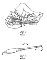
- Fig. 1 ultrasound guidance is used in order to properly locate the needle holding the seeds for brachytherapy or the needles for cryosurgery.
- Fig. 1 those skilled in the art will recognize the following bladder B, prostate P, urethra U, rectum R, perianal wall Pe, operator 10, ultrasonic probe 12, needle grid block 14, needle 16, needle core 18, and seeds 20.
- the typical bi-plane ultrasonic probe 22 used has a linear transducer array 24 to image the sagital or longitudinal view, and a micro-convex curved array 26 for the transverse view.
- the linear array is usually 50 mm long, and is not long enough to visualize the entire prostate in many patients.
- the micro-convex array 26 is at the end of the probe, and its imaging plane 28 does not intersect the linear array's imaging plane 30. This causes the operator to have to constantly move the probe to different positions along the rectum during the procedure. This is time consuming, and more importantly, causes the prostate to move, leading to more uncertainty as to where the seeds are being placed.
- Document US5891039 discloses an ultrasonic probe, which is formed by three integral transducers, i.e. a first, central transducer for scanning an artery axially and two lateral, further transducers, which are arranged parallel to one another and oriented perpendicularly to the first transducer in order to form transversal sectional images of the artery.
- document US6014473 discloses an ultrasonic imaging system, which includes an ultrasonic transducer having an image data array and a tracking array at each end of the image data array.
- the tracking arrays are oriented transversely to the image data array. Images from the image data array are used to reconstruct a three-dimensional representation of the target.
- a bi-plane transducer where three independent arrays are mounted, as defined in the independent claim 1.
- Preferred embodiments are defined in the dependent claims.
- the ultrasound system used with this ultrasonic probe can be used scan all three arrays sequentially.
- the two convex arrays are used to create one continuous image of the longitudinal plane.
- the micro-convex transducer images the transverse plane. Both images can be displayed simultaneously on the system monitor.
- At least one high voltage multiplexer integrated circuit may be built into the handle to switch the system electronics between the three different arrays of the probe.
- At least one additional multiplexer may be used to switch between the above mentioned probe and another probe.
- an additional ultrasonic imaging probe 19 may be placed on the abdominal wall of the patient 21 to image the prostate P from above.
- Probe 19 may have an array of, for example 128 transducers, in a flat or slightly concave configuration, and thus may be suited to image structures through the abdominal wall of the patient.
- the coordination of images produced by ultrasonic probe 42 and probe 19 is explained below with respect to Fig. 7 . Due to the location of probe 19, with the consequent need for the ultrasound produced and received by probe 19 to traverse a larger distance to and from the prostate than the ultrasound from probe 42, probe 19 may operate at a frequency lower than that used to excite the elements of the transducers of probe 42, or, in some applications, at the same frequency.
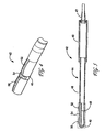
- FIG. 4 there is shown a perspective view of the operative or distal end portion 40 of an ultrasonic probe 42 incorporating features of the present invention.
- the present invention will be described with reference to the single embodiment shown in the drawings, it should be understood that the present invention can be embodied in many alternate forms of embodiments. In addition, any suitable size, shape or type of elements or materials could be used.
- ultrasonic probe 42 includes a substantially hollow probe housing 44 having a handle 46, a flexible cable guide 47 for a multi-wire cable (not shown in Fig. 5 ) a connecting tube 48, and end portion 40. These components (except for cable guide 47) may be constructed of a high strength engineering plastic, which retains its properties after multiple exposures to the heat required for cleaning and sterilization.
- End portion 40 has a solid insert 49, formed of an insulating material, and designed to support appropriate connecting wires (not shown) and three transducer arrays, as described below.
- the three transducer arrays of end portion 40 are for emitting and receiving ultrasound for the purpose of imaging the organs of a patient, and in particular, the prostate of a patient.
- These transducer arrays include a first convex array 50, a second convex array 52, and a micro-convex array 54.
- Transducer arrays 50 and 52 may each comprise 96 piezoelectric elements, having a pitch of 0.327 mm, an elevation of 5 mm, and a focal distance of 30 mm. Each array may subtend 30 degrees of arc, of a 60 mm radius of curvature. The frequency of resonance of the piezoelectric elements may be 6.5 MHz.
- Micro-convex transducer array 54 may include 128 elements. Alternatively, it may include 96 elements on a pitch of 0.215 mm, having an elevation of 5 mm and a focal distance of 30 mm, with the beam formed subtending an angle of 180 degrees.
- the frequency of resonance of the piezoelectric elements may be 6.5 MHz.
- multiplexing electronics may be located in handle 46 of housing 44.
- a cable (not shown in Fig. 5 ) having a 156 pin connector, such as a Cannon ZIF connector, may be used to connect the electronics to an electronics module ( Fig. 7 ) so that images may be generated and viewed.
- Fig. 6 illustrates the relationship between the sagital or longitudinal scan planes 60 and 62 generated by arrays 50 and 52 respectively, and the transverse scan 64 generated by micro-convex curved array 54.
- scan planes 60 and 62 are co-planar and partially overlap, thus permitting the entire prostate to be imaged along a single longitudinal plane without moving probe 42 in the rectum of the patient.
- Micro-convex transducer array 54 provides an image in a transverse scan plane 64 that is perpendicular to scan planes 60 and 62.
- the location of transducer array 54 between transducer arrays 50 and 52 means that the center of the prostate may be imaged in the transverse plane at the same time as the entire prostate is imaged in the longitudinal plane.
- the transducer arrays are aligned, or positioned with respect to one another, so that the transverse imaging array produces an image at (or in the general case, near) the center of the longitudinal image.
- ultrasonic transducer 19 and ultrasonic probe 42 are connected to an electronics module 100, which contains the circuitry necessary to excite the ultrasonic transducer 19 and ultrasonic probe 42 so as to send pulses of ultrasound into the patient, receive ultrasound reflected from internal structures and organs, and convert the signals, in a desired fashion to an image or images which may be interpreted in a medically significant fashion.
- electronics module 100 which contains the circuitry necessary to excite the ultrasonic transducer 19 and ultrasonic probe 42 so as to send pulses of ultrasound into the patient, receive ultrasound reflected from internal structures and organs, and convert the signals, in a desired fashion to an image or images which may be interpreted in a medically significant fashion.
- such modules are well known in the art.
- the use of ultrasonic transducer 19 and ultrasonic probe 42 gives rise to a unique arrangement of components.
- module 100 may be controlled by a microprocessor 102 connected by suitable lines 103 to a control input 104.
- Microprocessor 102 and control input 104 may be dedicated, hardwired components (such as a control panel with appropriate switches and knobs for control input 104) within module 100, or may represent, for example a personal computer and a keyboard, respectively, interfaced in a manner well know in the art to the remainder of module 100. If this is the case, suitable software may be provided to allow the keyboard to provide the control inputs typically provide in a module 100, such as brightness, contrast, color control, and control over parameter such as frequency of operation, focus, beam steering, system gain, and other necessary parameters, as more fully described below.
- a video processor 106 and a display 108 may also be dedicated components of the module 100 or the video driver card and monitor of the personal computer.
- Frequency control inputs provided by control input 104 are processed by microprocessor 102 and provided in suitable form to a frequency control 110.
- An output of frequency control 110 determines the rate at which entries in a table memory 112 are read out to each of sixty-four different transmitter channels represented as 114.
- Table memory 112 includes a multidimensional array of waveform values. The values that are read out for one of the dimensions is determined by a depth control 116, in response to inputs from microprocessor 102, as determined by input from control input 104. Thus the depth of display desired may be adjusted.
- the outputs of the transmitter channels are supplied to a transmit/receive switch 118, which is in turn connected to a 4:1 multiplexer or MUX 120 and sixty-four receiver channels, as represented by 122.
- the transmit/receive switch 118 serves to switch the sixty-four inputs of 4:1 MUX 120 between transmitter channels 114 and receiver channels 122 in a manner well known in the art.
- the 4:1 MUX 120 serves to switch the 64 transmitter and receiver channels between 128 elements of transducer 19 (sixty four elements at a time) and the 96 elements of one of the transducer arrays of ultrasonic probe 42. In other words, there are 256 outputs on one side of MUX 120 (the side connected to the cables to transducer 19 and probe 42) and 64 on the other side connected to transmit/receive switch 118. However, in the case of probe 42, some of the outputs are not used.
- MUX 120 may be a high voltage, low impedance switching multiplexer, such as that manufactured by Supertex, Inc., located in Sunnyvale, CA, USA.
- a second multiplexer or MUX 124 (in this case a 3:1 multiplexer located in the handle of probe 42) having 128 ports on each side, is used to successively connect 96 outputs of MUX 120 to the respective element of the three transducer element arrays of probe 42 described above.
- MUX 124 may be of the same general type as MUX 120.
- Receiver channels 122 provide suitable amplification and conditioning of analog signals returned by transducer elements of transducer 19 and probe 42 in response to reflections of ultrasound by structures within the patient.
- Gain control signals are provided to receiver channels 122 by a bus 125.
- the analog signals are converted to digital form by a series of sixty-four analog-to-digital converters or A/D's 126.
- a beam steering and focusing circuit 128 process the digital signals from the A/D's 126.
- the outputs of beam steering and focusing circuit 128 are provided to video processor 106 to provide a suitable representation of the patient on display 108.
- Microprocessor 102 has appropriate outputs 130 and 132 for controlling MUX 120 and MUX 124, as required to perform the sequence of switching described herein.
- the images provided on display 108 advantageously include those provided by the three transducer arrays of probe 42, as discussed above.
- an image generated by signals from probe 19 may also be displayed, preferably above the image resulting from the signals from probe 42.
- a top view may be displayed as well.
Description
- The present invention relates to apparatus used for ultrasonic imaging. More particularly, it relates to apparatus for simultaneous imaging in both longitudinal and transverse views. More specifically, it relates to apparatus for imaging for purposes of medical diagnosis and treatment, especially for diagnosis and treatment of organs such as the prostate.
- There are various situations in which it is necessary to do ultrasonic imaging to assist in medical diagnosis and treatment. For example, prostate cancer is one of the most common cancers found in men. Treatment options include "watchful waiting", hormonal therapy, brachytherapy, or surgery. Three types of surgery are used. The classical "open" procedure, radical prostetectomy, and the newly developed laproscopic and cryosurgery procedures. All procedures have risks. Both the open procedures and the laproscopic procedures have significant risks of causing impotence and incontinence. With both brachytherapy, and cryosurgery the prostate is left in vivo, and therefore the risk of complications is much lower, and the recovery time is quicker.
- In brachytherapy, trains of seeds are implanted in rows in the prostate. Cryosurgery is done in a similar fashion, except that cooling needles are inserted in eight to twelve locations in the prostate. Cold gases are circulated through the needles, and the prostate is monitored by ultrasound imaging for the formation of ice balls, which indicates proper operation of the device. Both of these procedures may be preformed under local anesthetic.
- As illustrated in
Fig. 1 , ultrasound guidance is used in order to properly locate the needle holding the seeds for brachytherapy or the needles for cryosurgery. InFig. 1 , those skilled in the art will recognize the following bladder B, prostate P, urethra U, rectum R, perianal wall Pe,operator 10,ultrasonic probe 12,needle grid block 14,needle 16,needle core 18, andseeds 20. - As illustrated in
Fig. 2 , in the prior art, the typical bi-planeultrasonic probe 22 used has alinear transducer array 24 to image the sagital or longitudinal view, and a micro-convexcurved array 26 for the transverse view. The linear array is usually 50 mm long, and is not long enough to visualize the entire prostate in many patients. - As illustrated in
Fig. 3 , themicro-convex array 26 is at the end of the probe, and itsimaging plane 28 does not intersect the linear array'simaging plane 30. This causes the operator to have to constantly move the probe to different positions along the rectum during the procedure. This is time consuming, and more importantly, causes the prostate to move, leading to more uncertainty as to where the seeds are being placed. - Document
US5891039 discloses an ultrasonic probe, which is formed by three integral transducers, i.e. a first, central transducer for scanning an artery axially and two lateral, further transducers, which are arranged parallel to one another and oriented perpendicularly to the first transducer in order to form transversal sectional images of the artery. - Further, document
US6014473 discloses an ultrasonic imaging system, which includes an ultrasonic transducer having an image data array and a tracking array at each end of the image data array. The tracking arrays are oriented transversely to the image data array. Images from the image data array are used to reconstruct a three-dimensional representation of the target. - It is an object of the invention to provide an ultrasonic probe that allows the entire prostate to be visualized at once.
- It is a further object of the invention to provide an ultrasonic probe that may be used to place the transverse scan in the middle of the prostate, thus eliminating the need to change the longitudinal position of the transducer along the rectum, and requiring rotation, which does not move the prostate significantly.
- It is yet another object of the invention to allow for more accurate and quicker needle placement for brachytherapy and cryosurgery when using a standard brachytherapy and cryosurgery apparatus.
- It is still another object of the invention to provide an ultrasonic probe that allows for the entire prostate to be imaged simultaneously in both longitudinal and transverse views.
- These objects and others are achieved in accordance with the invention by providing a bi-plane transducer where three independent arrays are mounted, as defined in the
independent claim 1. Preferred embodiments are defined in the dependent claims. There are two curved arrays typically subtending 30 degrees of arc of typically 60 mm radius mounted longitudinally on the housing, with a micro-convex array of typically 10 mm radius mounted transversely between the two larger curved arrays. - The ultrasound system used with this ultrasonic probe can be used scan all three arrays sequentially. The two convex arrays are used to create one continuous image of the longitudinal plane. The micro-convex transducer images the transverse plane. Both images can be displayed simultaneously on the system monitor. At least one high voltage multiplexer integrated circuit may be built into the handle to switch the system electronics between the three different arrays of the probe. At least one additional multiplexer may be used to switch between the above mentioned probe and another probe.
- The foregoing aspects and other features of the present invention are explained in the following description, taken in connection with the accompanying drawings, wherein:
-
Fig. 1 is a cross-sectional view of a patient with an ultrasonic probe in the rectum held in a brachytherapy device, and with an additional imaging probe. -
Fig. 2 is a perspective view of a prior art ultrasonic probe with a prior art transducer assembly. -
Fig. 3 illustrates the scan planes of the prior art device ofFig. 1 . -
Fig. 4 is a perspective view of the operative end of an ultrasonic probe in accordance with the invention. -
Fig. 5 is a cross sectional view of the embodiment of the invention illustrated inFig. 4 . -
Fig. 6 illustrates the scan planes of the ultrasonic probe in accordance with the invention. -
Fig. 7 is block diagram of a system using the ultrasonic probes, in accordance with the invention. - Referring again briefly to
Fig. 1 , in accordance with the invention, an additionalultrasonic imaging probe 19 may be placed on the abdominal wall of the patient 21 to image the prostate P from above.Probe 19 may have an array of, for example 128 transducers, in a flat or slightly concave configuration, and thus may be suited to image structures through the abdominal wall of the patient. The coordination of images produced byultrasonic probe 42 andprobe 19 is explained below with respect toFig. 7 . Due to the location ofprobe 19, with the consequent need for the ultrasound produced and received byprobe 19 to traverse a larger distance to and from the prostate than the ultrasound fromprobe 42,probe 19 may operate at a frequency lower than that used to excite the elements of the transducers ofprobe 42, or, in some applications, at the same frequency. - Referring to
Fig. 4 , there is shown a perspective view of the operative ordistal end portion 40 of anultrasonic probe 42 incorporating features of the present invention. Although the present invention will be described with reference to the single embodiment shown in the drawings, it should be understood that the present invention can be embodied in many alternate forms of embodiments. In addition, any suitable size, shape or type of elements or materials could be used. - Referring also to
Fig. 5 ,ultrasonic probe 42 includes a substantiallyhollow probe housing 44 having ahandle 46, aflexible cable guide 47 for a multi-wire cable (not shown inFig. 5 ) aconnecting tube 48, andend portion 40. These components (except for cable guide 47) may be constructed of a high strength engineering plastic, which retains its properties after multiple exposures to the heat required for cleaning and sterilization.End portion 40 has asolid insert 49, formed of an insulating material, and designed to support appropriate connecting wires (not shown) and three transducer arrays, as described below. - The three transducer arrays of
end portion 40 are for emitting and receiving ultrasound for the purpose of imaging the organs of a patient, and in particular, the prostate of a patient. These transducer arrays include a firstconvex array 50, a secondconvex array 52, and amicro-convex array 54. -
Transducer arrays -
Micro-convex transducer array 54 may include 128 elements. Alternatively, it may include 96 elements on a pitch of 0.215 mm, having an elevation of 5 mm and a focal distance of 30 mm, with the beam formed subtending an angle of 180 degrees. The frequency of resonance of the piezoelectric elements may be 6.5 MHz. - As noted above, multiplexing electronics may be located in
handle 46 ofhousing 44. A cable (not shown inFig. 5 ) having a 156 pin connector, such as a Cannon ZIF connector, may be used to connect the electronics to an electronics module (Fig. 7 ) so that images may be generated and viewed. -
Fig. 6 illustrates the relationship between the sagital or longitudinal scan planes 60 and 62 generated byarrays transverse scan 64 generated by micro-convexcurved array 54. It is noted that scan planes 60 and 62 are co-planar and partially overlap, thus permitting the entire prostate to be imaged along a single longitudinal plane without movingprobe 42 in the rectum of the patient.Micro-convex transducer array 54 provides an image in atransverse scan plane 64 that is perpendicular to scanplanes transducer array 54 betweentransducer arrays - Referring to
Fig. 7 ,ultrasonic transducer 19 andultrasonic probe 42 are connected to anelectronics module 100, which contains the circuitry necessary to excite theultrasonic transducer 19 andultrasonic probe 42 so as to send pulses of ultrasound into the patient, receive ultrasound reflected from internal structures and organs, and convert the signals, in a desired fashion to an image or images which may be interpreted in a medically significant fashion. In general, such modules are well known in the art. However, the use ofultrasonic transducer 19 andultrasonic probe 42 gives rise to a unique arrangement of components. - In general,
module 100 may be controlled by amicroprocessor 102 connected bysuitable lines 103 to acontrol input 104.Microprocessor 102 and controlinput 104 may be dedicated, hardwired components (such as a control panel with appropriate switches and knobs for control input 104) withinmodule 100, or may represent, for example a personal computer and a keyboard, respectively, interfaced in a manner well know in the art to the remainder ofmodule 100. If this is the case, suitable software may be provided to allow the keyboard to provide the control inputs typically provide in amodule 100, such as brightness, contrast, color control, and control over parameter such as frequency of operation, focus, beam steering, system gain, and other necessary parameters, as more fully described below. In a like manner, avideo processor 106 and adisplay 108 may also be dedicated components of themodule 100 or the video driver card and monitor of the personal computer. - Frequency control inputs provided by
control input 104 are processed bymicroprocessor 102 and provided in suitable form to afrequency control 110. An output offrequency control 110 determines the rate at which entries in atable memory 112 are read out to each of sixty-four different transmitter channels represented as 114.Table memory 112 includes a multidimensional array of waveform values. The values that are read out for one of the dimensions is determined by adepth control 116, in response to inputs frommicroprocessor 102, as determined by input fromcontrol input 104. Thus the depth of display desired may be adjusted. - The outputs of the transmitter channels are supplied to a transmit/receive
switch 118, which is in turn connected to a 4:1 multiplexer orMUX 120 and sixty-four receiver channels, as represented by 122. The transmit/receiveswitch 118 serves to switch the sixty-four inputs of 4:1MUX 120 between transmitter channels 114 andreceiver channels 122 in a manner well known in the art. - The 4:1
MUX 120 serves to switch the 64 transmitter and receiver channels between 128 elements of transducer 19 (sixty four elements at a time) and the 96 elements of one of the transducer arrays ofultrasonic probe 42. In other words, there are 256 outputs on one side of MUX 120 (the side connected to the cables totransducer 19 and probe 42) and 64 on the other side connected to transmit/receiveswitch 118. However, in the case ofprobe 42, some of the outputs are not used.MUX 120 may be a high voltage, low impedance switching multiplexer, such as that manufactured by Supertex, Inc., located in Sunnyvale, CA, USA. - A second multiplexer or MUX 124 (in this case a 3:1 multiplexer located in the handle of probe 42) having 128 ports on each side, is used to successively connect 96 outputs of
MUX 120 to the respective element of the three transducer element arrays ofprobe 42 described above.MUX 124 may be of the same general type asMUX 120. -
Receiver channels 122 provide suitable amplification and conditioning of analog signals returned by transducer elements oftransducer 19 andprobe 42 in response to reflections of ultrasound by structures within the patient. Gain control signals are provided toreceiver channels 122 by abus 125. The analog signals are converted to digital form by a series of sixty-four analog-to-digital converters or A/D's 126. As is well known in the art, the number of A/D output signals used to form an image is a function of depth of the image, generally with more channels being used for imaging at greater depth. A beam steering and focusingcircuit 128 process the digital signals from the A/D's 126. The outputs of beam steering and focusingcircuit 128 are provided tovideo processor 106 to provide a suitable representation of the patient ondisplay 108. -
Microprocessor 102 hasappropriate outputs MUX 120 andMUX 124, as required to perform the sequence of switching described herein. - The images provided on
display 108 advantageously include those provided by the three transducer arrays ofprobe 42, as discussed above. In addition, an image generated by signals fromprobe 19 may also be displayed, preferably above the image resulting from the signals fromprobe 42. Thus, in addition to imaging the transverse plane and the entire longitudinal plane of an organ, such as the prostate, or a defined region, a top view may be displayed as well. The various images, when taken together, provide an excellent, very precise view of the organ or image in three dimensions, allowing the precise location of structures and therefore the accurate placement of, for example, seeds or needles, for brachytherapy or cryosurgery, as described above. - It should be understood that the foregoing description is only illustrative of the invention. Accordingly, the present invention is intended to embrace all alternatives, modifications and variances which fall within the scope of the appended claims.
Claims (17)
- An ultrasonic probe (42) comprising:an elongate structure having a longitudinal axis;a first array of ultrasonic transducer elements (50) extending along an outer surface of said elongate structure in a direction generally parallel to said longitudinal axis so as to generate a first scan plane (60);a second array of ultrasonic transducer elements (52) extending along the outer surface of the elongate structure in a direction generally parallel to said longitudinal axis so as to generate a second scan plane (62) anda third array of ultrasonic transducer elements (54) extending about said elongate structure in a direction so that it images a plane perpendicular to that imaged by at least one of said first array and said second array, the third array being disposed in a space between said first array and said second array characterised in that the first scan plane and the second scan plane are configured to extend along said longitudinal axis.
- The probe of claim 1, wherein said first array, said second array and said third array are outwardly convex arrays.
- The probe of claim 2, wherein said third array has a radius of curvature smaller than that of said first array and said second array.
- The probe of claim 2, wherein said first array and said second array have a radius of curvature of substantially 60 millimeters.
- The probe of claim 2, wherein said third array has a radius of curvature of substantially 10 millimeters.
- The probe of claim 1, wherein said first array and said second array are configured so that beams formed by said first array and said second array subtend substantially thirty degrees of arc.
- The probe of claim 1, wherein said third array is configured so that a beam formed by said third array subtends substantially 180 degrees of arc.
- The probe of claim 1, further comprising a multiplexer for multiplexing connections to each of said first array, said second array and said third array.
- The probe of claim 8, wherein said multiplexer is disposed within said elongate structure.
- The probe of claim 1, wherein said first array and said second array are aligned so as to image a portion of a substantially continuous plan perpendicular to said plane imaged by said third array.
- The probe of claim 1, wherein each of said first array, said second array and said third array are comprised of transducer elements having a resonant frequency of 6.5 Megahertz.
- The probe of claim 1, in combination with a second probe, said second probe being capable of positioning so as to imaging in a plane perpendicular to a plan imaged by said first array and a plane imaged by said second array.
- The combination of claim 12, wherein said second probe comprises transducer elements with a resonant frequency of 6.5 Megahertz.
- The probe of claim 1, in combination with an electronics module, comprising : excitation circuitry for providing excitation energy to said probe; receiving circuitry for processing signals received by said probe; signal processing circuitry for processing signals from said receiving circuitry to produced processed image signals; and a display for displaying the processed image signals.
- The combination of claim 14, further comprising at least one of frequency setting circuitry for setting a frequency of the excitation energy; depth control circuitry for controlling the depth of images produced on said display; gain control circuitry for controlling gain of said receiving circuitry; and steering and focus control circuitry as a component of said signal processing circuitry for controlling the manner of operation of said signal processing circuitry.
- The combination of claim 14, wherein said excitation circuitry comprises a table memory for providing values of waveforms used to excite transducer elements of said probe.
- The combination of claim 14, further comprising analog to digital converters as components of said signal processing circuitry for converting analog signals from said receiving circuitry into digital signals.
Applications Claiming Priority (3)
| Application Number | Priority Date | Filing Date | Title |
|---|---|---|---|
| US44203403P | 2003-01-23 | 2003-01-23 | |
| US442034P | 2003-01-23 | ||
| PCT/US2004/001818 WO2004064614A2 (en) | 2003-01-23 | 2004-01-23 | Ultrasonic imaging device, system and method of use |
Publications (3)
| Publication Number | Publication Date |
|---|---|
| EP1594404A2 EP1594404A2 (en) | 2005-11-16 |
| EP1594404A4 EP1594404A4 (en) | 2010-12-08 |
| EP1594404B1 true EP1594404B1 (en) | 2013-09-11 |
Family
ID=32772009
Family Applications (1)
| Application Number | Title | Priority Date | Filing Date |
|---|---|---|---|
| EP04704866.5A Expired - Lifetime EP1594404B1 (en) | 2003-01-23 | 2004-01-23 | Ultrasonic imaging device and system |
Country Status (3)
| Country | Link |
|---|---|
| US (1) | US7090643B2 (en) |
| EP (1) | EP1594404B1 (en) |
| WO (1) | WO2004064614A2 (en) |
Cited By (15)
| Publication number | Priority date | Publication date | Assignee | Title |
|---|---|---|---|---|
| US9072495B2 (en) | 2006-10-25 | 2015-07-07 | Maui Imaging, Inc. | Method and apparatus to produce ultrasonic images using multiple apertures |
| US9146313B2 (en) | 2006-09-14 | 2015-09-29 | Maui Imaging, Inc. | Point source transmission and speed-of-sound correction using multi-aperature ultrasound imaging |
| US9192355B2 (en) | 2006-02-06 | 2015-11-24 | Maui Imaging, Inc. | Multiple aperture ultrasound array alignment fixture |
| US9220478B2 (en) | 2010-04-14 | 2015-12-29 | Maui Imaging, Inc. | Concave ultrasound transducers and 3D arrays |
| US9265484B2 (en) | 2011-12-29 | 2016-02-23 | Maui Imaging, Inc. | M-mode ultrasound imaging of arbitrary paths |
| US9282945B2 (en) | 2009-04-14 | 2016-03-15 | Maui Imaging, Inc. | Calibration of ultrasound probes |
| US9339256B2 (en) | 2007-10-01 | 2016-05-17 | Maui Imaging, Inc. | Determining material stiffness using multiple aperture ultrasound |
| US9510806B2 (en) | 2013-03-13 | 2016-12-06 | Maui Imaging, Inc. | Alignment of ultrasound transducer arrays and multiple aperture probe assembly |
| US9572549B2 (en) | 2012-08-10 | 2017-02-21 | Maui Imaging, Inc. | Calibration of multiple aperture ultrasound probes |
| US9582876B2 (en) | 2006-02-06 | 2017-02-28 | Maui Imaging, Inc. | Method and apparatus to visualize the coronary arteries using ultrasound |
| US9668714B2 (en) | 2010-04-14 | 2017-06-06 | Maui Imaging, Inc. | Systems and methods for improving ultrasound image quality by applying weighting factors |
| US9883848B2 (en) | 2013-09-13 | 2018-02-06 | Maui Imaging, Inc. | Ultrasound imaging using apparent point-source transmit transducer |
| US9986969B2 (en) | 2012-08-21 | 2018-06-05 | Maui Imaging, Inc. | Ultrasound imaging system memory architecture |
| US10226234B2 (en) | 2011-12-01 | 2019-03-12 | Maui Imaging, Inc. | Motion detection using ping-based and multiple aperture doppler ultrasound |
| US10856846B2 (en) | 2016-01-27 | 2020-12-08 | Maui Imaging, Inc. | Ultrasound imaging with sparse array probes |
Families Citing this family (34)
| Publication number | Priority date | Publication date | Assignee | Title |
|---|---|---|---|---|
| US20050096545A1 (en) * | 2003-10-30 | 2005-05-05 | Haider Bruno H. | Methods and apparatus for transducer probe |
| JP4559870B2 (en) * | 2005-02-10 | 2010-10-13 | 株式会社東芝 | Ultrasound probe for puncture |
| US7527593B2 (en) * | 2005-06-11 | 2009-05-05 | Fidel Howard F | Active template guide plate and system and method for utilizing same |
| EP1998679B1 (en) * | 2006-03-24 | 2019-10-16 | B-K Medical ApS | Ultrasound probe |
| US10201324B2 (en) | 2007-05-04 | 2019-02-12 | Delphinus Medical Technologies, Inc. | Patient interface system |
| US20090030317A1 (en) * | 2007-07-25 | 2009-01-29 | Mayo Foundation For Medical Education And Research | Ultrasonic imaging devices, systems, and methods |
| JP5085250B2 (en) * | 2007-09-21 | 2012-11-28 | オリンパスメディカルシステムズ株式会社 | Ultrasonic diagnostic equipment |
| JP5002402B2 (en) * | 2007-10-03 | 2012-08-15 | 株式会社東芝 | Ultrasonic probe and ultrasonic diagnostic apparatus |
| US8439907B2 (en) * | 2007-11-07 | 2013-05-14 | Mirabilis Medica Inc. | Hemostatic tissue tunnel generator for inserting treatment apparatus into tissue of a patient |
| US20090227874A1 (en) * | 2007-11-09 | 2009-09-10 | Eigen, Inc. | Holder assembly for a medical imaging instrument |
| US20090326372A1 (en) * | 2008-06-30 | 2009-12-31 | Darlington Gregory | Compound Imaging with HIFU Transducer and Use of Pseudo 3D Imaging |
| US9050449B2 (en) | 2008-10-03 | 2015-06-09 | Mirabilis Medica, Inc. | System for treating a volume of tissue with high intensity focused ultrasound |
| CA2739425A1 (en) | 2008-10-03 | 2010-04-08 | Mirabilis Medica, Inc. | Method and apparatus for treating tissues with hifu |
| US9144421B1 (en) | 2008-12-17 | 2015-09-29 | Mirabilis Medica Inc. | Optimization of acoustic window and target depth for transabdominal ultrasound treatment or imaging of the uterus |
| CN102869301B (en) | 2010-02-12 | 2016-06-29 | 戴尔菲纳斯医疗科技公司 | The method characterizing the tissue of patient |
| WO2011100691A1 (en) | 2010-02-12 | 2011-08-18 | Delphinus Medical Technologies, Inc. | Method of characterizing the pathological response of tissue to a treatmant plan |
| CN102138809A (en) * | 2011-02-15 | 2011-08-03 | 福建师范大学 | Opto-acoustic scan imaging method and device for detecting prostate |
| JP5976441B2 (en) * | 2011-08-03 | 2016-08-23 | 東芝メディカルシステムズ株式会社 | Ultrasonic probe and ultrasonic diagnostic apparatus |
| CN102415906B (en) * | 2011-09-06 | 2013-10-16 | 深圳市开立科技有限公司 | Tri-plane ultrasonic probe |
| WO2013038217A1 (en) * | 2011-09-12 | 2013-03-21 | B-K Medical Aps | Ultrasound imaging console |
| US9877699B2 (en) | 2012-03-26 | 2018-01-30 | Teratech Corporation | Tablet ultrasound system |
| US10667790B2 (en) | 2012-03-26 | 2020-06-02 | Teratech Corporation | Tablet ultrasound system |
| WO2013173369A2 (en) * | 2012-05-14 | 2013-11-21 | Delphinus Medical Technologies, Inc. | System and method for performing an image-guided biopsy |
| US9763641B2 (en) | 2012-08-30 | 2017-09-19 | Delphinus Medical Technologies, Inc. | Method and system for imaging a volume of tissue with tissue boundary detection |
| US10123770B2 (en) | 2013-03-13 | 2018-11-13 | Delphinus Medical Technologies, Inc. | Patient support system |
| CN104107067A (en) * | 2013-04-16 | 2014-10-22 | 深圳迈瑞生物医疗电子股份有限公司 | Ultrasonic diagnosis equipment and ultrasonic diagnosis method supporting multi-probe synchronous scanning |
| US10143443B2 (en) | 2014-05-05 | 2018-12-04 | Delphinus Medical Technologies, Inc. | Method for representing tissue stiffness |
| US10743837B2 (en) | 2014-08-04 | 2020-08-18 | Delphinus Medical Technologies, Inc. | Ultrasound waveform tomography method and system |
| US10285667B2 (en) | 2014-08-05 | 2019-05-14 | Delphinus Medical Technologies, Inc. | Method for generating an enhanced image of a volume of tissue |
| US10401493B2 (en) | 2014-08-18 | 2019-09-03 | Maui Imaging, Inc. | Network-based ultrasound imaging system |
| EP3389499A4 (en) * | 2015-12-16 | 2019-07-17 | Glo-Tip, LLC | Needle tracking transducer array methods and apparatus |
| EP3632334A1 (en) * | 2018-10-05 | 2020-04-08 | Koninklijke Philips N.V. | Interventional device with an ultrasound transducer |
| GB201817501D0 (en) * | 2018-10-26 | 2018-12-12 | Dolphitech As | Scanning apparatus |
| WO2020118709A1 (en) * | 2018-12-14 | 2020-06-18 | 深圳先进技术研究院 | Ultrasonic endoscope system |
Family Cites Families (29)
| Publication number | Priority date | Publication date | Assignee | Title |
|---|---|---|---|---|
| US4819650A (en) * | 1987-10-30 | 1989-04-11 | Wayne State University | Biplane probe including centerline highlighting |
| US5121361A (en) | 1989-09-29 | 1992-06-09 | Acoustic Imaging Technologies Corporation | Programmable beam former |
| US5103129A (en) * | 1990-07-26 | 1992-04-07 | Acoustic Imaging Technologies Corporation | Fixed origin biplane ultrasonic transducer |
| DE4207463C2 (en) * | 1992-03-10 | 1996-03-28 | Siemens Ag | Arrangement for the therapy of tissue with ultrasound |
| US5391197A (en) * | 1992-11-13 | 1995-02-21 | Dornier Medical Systems, Inc. | Ultrasound thermotherapy probe |
| US5398691A (en) * | 1993-09-03 | 1995-03-21 | University Of Washington | Method and apparatus for three-dimensional translumenal ultrasonic imaging |
| US5471988A (en) * | 1993-12-24 | 1995-12-05 | Olympus Optical Co., Ltd. | Ultrasonic diagnosis and therapy system in which focusing point of therapeutic ultrasonic wave is locked at predetermined position within observation ultrasonic scanning range |
| US5413107A (en) * | 1994-02-16 | 1995-05-09 | Tetrad Corporation | Ultrasonic probe having articulated structure and rotatable transducer head |
| GB2287375B (en) * | 1994-03-11 | 1998-04-15 | Intravascular Res Ltd | Ultrasonic transducer array and method of manufacturing the same |
| AU1331497A (en) | 1995-12-18 | 1997-07-14 | Kerisma Medical Products, L.L.C. | Fiberoptic-guided interstitial seed manual applicator and seed cartridge |
| EP0883860B1 (en) * | 1996-02-29 | 2006-08-23 | Acuson Corporation | Multiple ultrasound image registration system, method and transducer |
| FR2759892A1 (en) * | 1996-12-31 | 1998-08-28 | Philips Electronics Nv | ULTRASONIC ECHOGRAPHY SYSTEM FOR ARTERY EXAMINATION |
| US5842991A (en) * | 1997-02-20 | 1998-12-01 | Barabash; Leonid S. | Ultrasound transducer with extended field of view |
| US5876345A (en) * | 1997-02-27 | 1999-03-02 | Acuson Corporation | Ultrasonic catheter, system and method for two dimensional imaging or three-dimensional reconstruction |
| US6045508A (en) | 1997-02-27 | 2000-04-04 | Acuson Corporation | Ultrasonic probe, system and method for two-dimensional imaging or three-dimensional reconstruction |
| US5860926A (en) * | 1997-07-25 | 1999-01-19 | Barabash; Leonid S. | Method and ultrasound apparatus for fast acquisition of two dimensional images |
| US6120453A (en) * | 1997-11-17 | 2000-09-19 | Sharp; William A. | Three-dimensional ultrasound system based on the coordination of multiple ultrasonic transducers |
| GB9726664D0 (en) | 1997-12-17 | 1998-02-18 | Nycomed Imaging As | Improvements in or relating to ultrasonography |
| US5905692A (en) | 1997-12-31 | 1999-05-18 | Analogic Corporation | Digital ultrasound beamformer |
| DK176387B1 (en) * | 1998-01-07 | 2007-10-22 | Bk Medical Aps | Apparatus for insertion into the human body |
| IL123311A0 (en) * | 1998-02-15 | 1998-09-24 | Diasonics Israel Ltd | Multi-frequency ultrasonic imaging and therapy |
| US6059731A (en) * | 1998-08-19 | 2000-05-09 | Mayo Foundation For Medical Education And Research | Simultaneous side-and-end viewing underfluid catheter |
| US6423002B1 (en) * | 1999-06-24 | 2002-07-23 | Acuson Corporation | Intra-operative diagnostic ultrasound multiple-array transducer probe and optional surgical tool |
| US6454696B1 (en) | 1999-07-23 | 2002-09-24 | Nucletron B. V. | Device and method for implanting radioactive seeds |
| US6610013B1 (en) * | 1999-10-01 | 2003-08-26 | Life Imaging Systems, Inc. | 3D ultrasound-guided intraoperative prostate brachytherapy |
| US6511427B1 (en) * | 2000-03-10 | 2003-01-28 | Acuson Corporation | System and method for assessing body-tissue properties using a medical ultrasound transducer probe with a body-tissue parameter measurement mechanism |
| US6422997B1 (en) | 2000-08-25 | 2002-07-23 | Neoseed Technology Llc | Prostate visualization device and methods of use |
| US6685644B2 (en) * | 2001-04-24 | 2004-02-03 | Kabushiki Kaisha Toshiba | Ultrasound diagnostic apparatus |
| US6709397B2 (en) | 2001-10-16 | 2004-03-23 | Envisioneering, L.L.C. | Scanning probe |
-
2004
- 2004-01-23 US US10/763,341 patent/US7090643B2/en not_active Expired - Lifetime
- 2004-01-23 EP EP04704866.5A patent/EP1594404B1/en not_active Expired - Lifetime
- 2004-01-23 WO PCT/US2004/001818 patent/WO2004064614A2/en active Application Filing
Cited By (30)
| Publication number | Priority date | Publication date | Assignee | Title |
|---|---|---|---|---|
| US9192355B2 (en) | 2006-02-06 | 2015-11-24 | Maui Imaging, Inc. | Multiple aperture ultrasound array alignment fixture |
| US9582876B2 (en) | 2006-02-06 | 2017-02-28 | Maui Imaging, Inc. | Method and apparatus to visualize the coronary arteries using ultrasound |
| US9526475B2 (en) | 2006-09-14 | 2016-12-27 | Maui Imaging, Inc. | Point source transmission and speed-of-sound correction using multi-aperture ultrasound imaging |
| US9146313B2 (en) | 2006-09-14 | 2015-09-29 | Maui Imaging, Inc. | Point source transmission and speed-of-sound correction using multi-aperature ultrasound imaging |
| US9986975B2 (en) | 2006-09-14 | 2018-06-05 | Maui Imaging, Inc. | Point source transmission and speed-of-sound correction using multi-aperture ultrasound imaging |
| US10130333B2 (en) | 2006-10-25 | 2018-11-20 | Maui Imaging, Inc. | Method and apparatus to produce ultrasonic images using multiple apertures |
| US9420994B2 (en) | 2006-10-25 | 2016-08-23 | Maui Imaging, Inc. | Method and apparatus to produce ultrasonic images using multiple apertures |
| US9072495B2 (en) | 2006-10-25 | 2015-07-07 | Maui Imaging, Inc. | Method and apparatus to produce ultrasonic images using multiple apertures |
| US9339256B2 (en) | 2007-10-01 | 2016-05-17 | Maui Imaging, Inc. | Determining material stiffness using multiple aperture ultrasound |
| US10675000B2 (en) | 2007-10-01 | 2020-06-09 | Maui Imaging, Inc. | Determining material stiffness using multiple aperture ultrasound |
| US9282945B2 (en) | 2009-04-14 | 2016-03-15 | Maui Imaging, Inc. | Calibration of ultrasound probes |
| US11051791B2 (en) * | 2009-04-14 | 2021-07-06 | Maui Imaging, Inc. | Calibration of ultrasound probes |
| US10206662B2 (en) | 2009-04-14 | 2019-02-19 | Maui Imaging, Inc. | Calibration of ultrasound probes |
| US10835208B2 (en) | 2010-04-14 | 2020-11-17 | Maui Imaging, Inc. | Concave ultrasound transducers and 3D arrays |
| US11172911B2 (en) | 2010-04-14 | 2021-11-16 | Maui Imaging, Inc. | Systems and methods for improving ultrasound image quality by applying weighting factors |
| US9220478B2 (en) | 2010-04-14 | 2015-12-29 | Maui Imaging, Inc. | Concave ultrasound transducers and 3D arrays |
| US9668714B2 (en) | 2010-04-14 | 2017-06-06 | Maui Imaging, Inc. | Systems and methods for improving ultrasound image quality by applying weighting factors |
| US9247926B2 (en) | 2010-04-14 | 2016-02-02 | Maui Imaging, Inc. | Concave ultrasound transducers and 3D arrays |
| US10226234B2 (en) | 2011-12-01 | 2019-03-12 | Maui Imaging, Inc. | Motion detection using ping-based and multiple aperture doppler ultrasound |
| US10617384B2 (en) | 2011-12-29 | 2020-04-14 | Maui Imaging, Inc. | M-mode ultrasound imaging of arbitrary paths |
| US9265484B2 (en) | 2011-12-29 | 2016-02-23 | Maui Imaging, Inc. | M-mode ultrasound imaging of arbitrary paths |
| US10064605B2 (en) | 2012-08-10 | 2018-09-04 | Maui Imaging, Inc. | Calibration of multiple aperture ultrasound probes |
| US9572549B2 (en) | 2012-08-10 | 2017-02-21 | Maui Imaging, Inc. | Calibration of multiple aperture ultrasound probes |
| US11253233B2 (en) | 2012-08-10 | 2022-02-22 | Maui Imaging, Inc. | Calibration of multiple aperture ultrasound probes |
| US9986969B2 (en) | 2012-08-21 | 2018-06-05 | Maui Imaging, Inc. | Ultrasound imaging system memory architecture |
| US10267913B2 (en) | 2013-03-13 | 2019-04-23 | Maui Imaging, Inc. | Alignment of ultrasound transducer arrays and multiple aperture probe assembly |
| US9510806B2 (en) | 2013-03-13 | 2016-12-06 | Maui Imaging, Inc. | Alignment of ultrasound transducer arrays and multiple aperture probe assembly |
| US10653392B2 (en) | 2013-09-13 | 2020-05-19 | Maui Imaging, Inc. | Ultrasound imaging using apparent point-source transmit transducer |
| US9883848B2 (en) | 2013-09-13 | 2018-02-06 | Maui Imaging, Inc. | Ultrasound imaging using apparent point-source transmit transducer |
| US10856846B2 (en) | 2016-01-27 | 2020-12-08 | Maui Imaging, Inc. | Ultrasound imaging with sparse array probes |
Also Published As
| Publication number | Publication date |
|---|---|
| US7090643B2 (en) | 2006-08-15 |
| EP1594404A2 (en) | 2005-11-16 |
| US20040152986A1 (en) | 2004-08-05 |
| WO2004064614A2 (en) | 2004-08-05 |
| EP1594404A4 (en) | 2010-12-08 |
| WO2004064614A3 (en) | 2005-07-07 |
Similar Documents
| Publication | Publication Date | Title |
|---|---|---|
| EP1594404B1 (en) | Ultrasonic imaging device and system | |
| EP0955010B1 (en) | Biplane ultrasound imaging for the guidance of intracavitary probes | |
| US5699805A (en) | Longitudinal multiplane ultrasound transducer underfluid catheter system | |
| US6059731A (en) | Simultaneous side-and-end viewing underfluid catheter | |
| US20070161905A1 (en) | Intrauterine ultrasound and method for use | |
| US6572551B1 (en) | Imaging catheters for volumetric intraluminal ultrasound imaging | |
| EP1998679B1 (en) | Ultrasound probe | |
| US20050085731A1 (en) | Ultrasound transducer finger probe | |
| JP4842726B2 (en) | Ultrasonic inspection equipment | |
| US20070232924A1 (en) | Ultrasonic probe and ultrasonic diagnosing apparatus | |
| JP2007068918A (en) | Ultrasonic probe and ultrasonic diagnosis apparatus | |
| EP1629778B1 (en) | Ultrasonic endoscope | |
| US20090082674A1 (en) | Ultrasound diagnostic apparatus | |
| JP4266611B2 (en) | Ultrasonic probe, ultrasonic endoscope, and ultrasonic diagnostic apparatus | |
| JP4488288B2 (en) | Ultrasound diagnostic imaging equipment | |
| US7111515B2 (en) | Ultrasonic diagnostic apparatus and driving method therefor | |
| JP2005168766A (en) | Ultrasonic probe | |
| US7691065B2 (en) | Ultrasonic probe and ultrasonic diagnostic device | |
| JPH04183455A (en) | Vibration piece array for ultrasonic body cavity probe | |
| JPH10277040A (en) | Ultrasonic diagnostic device | |
| US11844647B2 (en) | Ultrasound catheter with adjustable apertures for multi-plane imaging | |
| Felix et al. | Biplane ultrasound arrays with integrated multiplexing solution for enhanced diagnostic accuracy in endorectal and transvaginal imaging | |
| JPH03277353A (en) | Ultrasonic diagnostic device | |
| JPH03292943A (en) | Ultrasonic diagnostic apparatus |
Legal Events
| Date | Code | Title | Description |
|---|---|---|---|
| PUAI | Public reference made under article 153(3) epc to a published international application that has entered the european phase |
Free format text: ORIGINAL CODE: 0009012 |
|
| 17P | Request for examination filed |
Effective date: 20050818 |
|
| AK | Designated contracting states |
Kind code of ref document: A2 Designated state(s): AT BE BG CH CY CZ DE DK EE ES FI FR GB GR HU IE IT LI LU MC NL PT RO SE SI SK TR |
|
| AX | Request for extension of the european patent |
Extension state: AL LT LV MK |
|
| DAX | Request for extension of the european patent (deleted) | ||
| A4 | Supplementary search report drawn up and despatched |
Effective date: 20101105 |
|
| 17Q | First examination report despatched |
Effective date: 20110909 |
|
| GRAP | Despatch of communication of intention to grant a patent |
Free format text: ORIGINAL CODE: EPIDOSNIGR1 |
|
| GRAS | Grant fee paid |
Free format text: ORIGINAL CODE: EPIDOSNIGR3 |
|
| GRAA | (expected) grant |
Free format text: ORIGINAL CODE: 0009210 |
|
| AK | Designated contracting states |
Kind code of ref document: B1 Designated state(s): AT BE BG CH CY CZ DE DK EE ES FI FR GB GR HU IE IT LI LU MC NL PT RO SE SI SK TR |
|
| REG | Reference to a national code |
Ref country code: GB Ref legal event code: FG4D |
|
| REG | Reference to a national code |
Ref country code: CH Ref legal event code: EP |
|
| REG | Reference to a national code |
Ref country code: AT Ref legal event code: REF Ref document number: 631167 Country of ref document: AT Kind code of ref document: T Effective date: 20130915 |
|
| REG | Reference to a national code |
Ref country code: IE Ref legal event code: FG4D |
|
| REG | Reference to a national code |
Ref country code: DE Ref legal event code: R096 Ref document number: 602004043295 Country of ref document: DE Effective date: 20131107 |
|
| PG25 | Lapsed in a contracting state [announced via postgrant information from national office to epo] |
Ref country code: SE Free format text: LAPSE BECAUSE OF FAILURE TO SUBMIT A TRANSLATION OF THE DESCRIPTION OR TO PAY THE FEE WITHIN THE PRESCRIBED TIME-LIMIT Effective date: 20130911 Ref country code: CY Free format text: LAPSE BECAUSE OF FAILURE TO SUBMIT A TRANSLATION OF THE DESCRIPTION OR TO PAY THE FEE WITHIN THE PRESCRIBED TIME-LIMIT Effective date: 20130619 |
|
| REG | Reference to a national code |
Ref country code: NL Ref legal event code: VDEP Effective date: 20130911 |
|
| REG | Reference to a national code |
Ref country code: AT Ref legal event code: MK05 Ref document number: 631167 Country of ref document: AT Kind code of ref document: T Effective date: 20130911 |
|
| PG25 | Lapsed in a contracting state [announced via postgrant information from national office to epo] |
Ref country code: SI Free format text: LAPSE BECAUSE OF FAILURE TO SUBMIT A TRANSLATION OF THE DESCRIPTION OR TO PAY THE FEE WITHIN THE PRESCRIBED TIME-LIMIT Effective date: 20130911 Ref country code: GR Free format text: LAPSE BECAUSE OF FAILURE TO SUBMIT A TRANSLATION OF THE DESCRIPTION OR TO PAY THE FEE WITHIN THE PRESCRIBED TIME-LIMIT Effective date: 20131212 Ref country code: FI Free format text: LAPSE BECAUSE OF FAILURE TO SUBMIT A TRANSLATION OF THE DESCRIPTION OR TO PAY THE FEE WITHIN THE PRESCRIBED TIME-LIMIT Effective date: 20130911 |
|
| PG25 | Lapsed in a contracting state [announced via postgrant information from national office to epo] |
Ref country code: CY Free format text: LAPSE BECAUSE OF FAILURE TO SUBMIT A TRANSLATION OF THE DESCRIPTION OR TO PAY THE FEE WITHIN THE PRESCRIBED TIME-LIMIT Effective date: 20130911 Ref country code: BE Free format text: LAPSE BECAUSE OF FAILURE TO SUBMIT A TRANSLATION OF THE DESCRIPTION OR TO PAY THE FEE WITHIN THE PRESCRIBED TIME-LIMIT Effective date: 20130911 |
|
| PG25 | Lapsed in a contracting state [announced via postgrant information from national office to epo] |
Ref country code: CZ Free format text: LAPSE BECAUSE OF FAILURE TO SUBMIT A TRANSLATION OF THE DESCRIPTION OR TO PAY THE FEE WITHIN THE PRESCRIBED TIME-LIMIT Effective date: 20130911 Ref country code: NL Free format text: LAPSE BECAUSE OF FAILURE TO SUBMIT A TRANSLATION OF THE DESCRIPTION OR TO PAY THE FEE WITHIN THE PRESCRIBED TIME-LIMIT Effective date: 20130911 Ref country code: SK Free format text: LAPSE BECAUSE OF FAILURE TO SUBMIT A TRANSLATION OF THE DESCRIPTION OR TO PAY THE FEE WITHIN THE PRESCRIBED TIME-LIMIT Effective date: 20130911 Ref country code: EE Free format text: LAPSE BECAUSE OF FAILURE TO SUBMIT A TRANSLATION OF THE DESCRIPTION OR TO PAY THE FEE WITHIN THE PRESCRIBED TIME-LIMIT Effective date: 20130911 Ref country code: RO Free format text: LAPSE BECAUSE OF FAILURE TO SUBMIT A TRANSLATION OF THE DESCRIPTION OR TO PAY THE FEE WITHIN THE PRESCRIBED TIME-LIMIT Effective date: 20130911 |
|
| PG25 | Lapsed in a contracting state [announced via postgrant information from national office to epo] |
Ref country code: ES Free format text: LAPSE BECAUSE OF FAILURE TO SUBMIT A TRANSLATION OF THE DESCRIPTION OR TO PAY THE FEE WITHIN THE PRESCRIBED TIME-LIMIT Effective date: 20130911 Ref country code: AT Free format text: LAPSE BECAUSE OF FAILURE TO SUBMIT A TRANSLATION OF THE DESCRIPTION OR TO PAY THE FEE WITHIN THE PRESCRIBED TIME-LIMIT Effective date: 20130911 |
|
| REG | Reference to a national code |
Ref country code: DE Ref legal event code: R097 Ref document number: 602004043295 Country of ref document: DE |
|
| PG25 | Lapsed in a contracting state [announced via postgrant information from national office to epo] |
Ref country code: PT Free format text: LAPSE BECAUSE OF FAILURE TO SUBMIT A TRANSLATION OF THE DESCRIPTION OR TO PAY THE FEE WITHIN THE PRESCRIBED TIME-LIMIT Effective date: 20140113 |
|
| PLBE | No opposition filed within time limit |
Free format text: ORIGINAL CODE: 0009261 |
|
| STAA | Information on the status of an ep patent application or granted ep patent |
Free format text: STATUS: NO OPPOSITION FILED WITHIN TIME LIMIT |
|
| REG | Reference to a national code |
Ref country code: DE Ref legal event code: R119 Ref document number: 602004043295 Country of ref document: DE |
|
| 26N | No opposition filed |
Effective date: 20140612 |
|
| PG25 | Lapsed in a contracting state [announced via postgrant information from national office to epo] |
Ref country code: LU Free format text: LAPSE BECAUSE OF FAILURE TO SUBMIT A TRANSLATION OF THE DESCRIPTION OR TO PAY THE FEE WITHIN THE PRESCRIBED TIME-LIMIT Effective date: 20140123 Ref country code: MC Free format text: LAPSE BECAUSE OF FAILURE TO SUBMIT A TRANSLATION OF THE DESCRIPTION OR TO PAY THE FEE WITHIN THE PRESCRIBED TIME-LIMIT Effective date: 20130911 Ref country code: IT Free format text: LAPSE BECAUSE OF FAILURE TO SUBMIT A TRANSLATION OF THE DESCRIPTION OR TO PAY THE FEE WITHIN THE PRESCRIBED TIME-LIMIT Effective date: 20130911 |
|
| REG | Reference to a national code |
Ref country code: CH Ref legal event code: PL |
|
| GBPC | Gb: european patent ceased through non-payment of renewal fee |
Effective date: 20140123 |
|
| REG | Reference to a national code |
Ref country code: DE Ref legal event code: R097 Ref document number: 602004043295 Country of ref document: DE Effective date: 20140612 |
|
| PG25 | Lapsed in a contracting state [announced via postgrant information from national office to epo] |
Ref country code: DK Free format text: LAPSE BECAUSE OF FAILURE TO SUBMIT A TRANSLATION OF THE DESCRIPTION OR TO PAY THE FEE WITHIN THE PRESCRIBED TIME-LIMIT Effective date: 20130911 |
|
| PG25 | Lapsed in a contracting state [announced via postgrant information from national office to epo] |
Ref country code: CH Free format text: LAPSE BECAUSE OF NON-PAYMENT OF DUE FEES Effective date: 20140131 Ref country code: DE Free format text: LAPSE BECAUSE OF NON-PAYMENT OF DUE FEES Effective date: 20140801 Ref country code: LI Free format text: LAPSE BECAUSE OF NON-PAYMENT OF DUE FEES Effective date: 20140131 |
|
| REG | Reference to a national code |
Ref country code: FR Ref legal event code: ST Effective date: 20140930 |
|
| REG | Reference to a national code |
Ref country code: IE Ref legal event code: MM4A |
|
| REG | Reference to a national code |
Ref country code: DE Ref legal event code: R119 Ref document number: 602004043295 Country of ref document: DE Effective date: 20140801 |
|
| PG25 | Lapsed in a contracting state [announced via postgrant information from national office to epo] |
Ref country code: FR Free format text: LAPSE BECAUSE OF NON-PAYMENT OF DUE FEES Effective date: 20140131 Ref country code: GB Free format text: LAPSE BECAUSE OF NON-PAYMENT OF DUE FEES Effective date: 20140123 |
|
| PG25 | Lapsed in a contracting state [announced via postgrant information from national office to epo] |
Ref country code: IE Free format text: LAPSE BECAUSE OF NON-PAYMENT OF DUE FEES Effective date: 20140123 |
|
| PG25 | Lapsed in a contracting state [announced via postgrant information from national office to epo] |
Ref country code: BG Free format text: LAPSE BECAUSE OF FAILURE TO SUBMIT A TRANSLATION OF THE DESCRIPTION OR TO PAY THE FEE WITHIN THE PRESCRIBED TIME-LIMIT Effective date: 20130911 |
|
| PG25 | Lapsed in a contracting state [announced via postgrant information from national office to epo] |
Ref country code: HU Free format text: LAPSE BECAUSE OF FAILURE TO SUBMIT A TRANSLATION OF THE DESCRIPTION OR TO PAY THE FEE WITHIN THE PRESCRIBED TIME-LIMIT; INVALID AB INITIO Effective date: 20040123 Ref country code: TR Free format text: LAPSE BECAUSE OF FAILURE TO SUBMIT A TRANSLATION OF THE DESCRIPTION OR TO PAY THE FEE WITHIN THE PRESCRIBED TIME-LIMIT Effective date: 20130911 |