EP1593357B1 - Flexible spacer - Google Patents
Flexible spacer Download PDFInfo
- Publication number
- EP1593357B1 EP1593357B1 EP05009856.5A EP05009856A EP1593357B1 EP 1593357 B1 EP1593357 B1 EP 1593357B1 EP 05009856 A EP05009856 A EP 05009856A EP 1593357 B1 EP1593357 B1 EP 1593357B1
- Authority
- EP
- European Patent Office
- Prior art keywords
- tube
- space holder
- accordance
- adjacent
- recesses
- Prior art date
- Legal status (The legal status is an assumption and is not a legal conclusion. Google has not performed a legal analysis and makes no representation as to the accuracy of the status listed.)
- Not-in-force
Links
- 125000006850 spacer group Chemical group 0.000 title description 5
- 239000000463 material Substances 0.000 claims description 33
- 239000007943 implant Substances 0.000 claims description 8
- 239000000560 biocompatible material Substances 0.000 claims description 4
- 241001465754 Metazoa Species 0.000 claims description 3
- 229910001069 Ti alloy Inorganic materials 0.000 claims description 3
- RTAQQCXQSZGOHL-UHFFFAOYSA-N Titanium Chemical compound [Ti] RTAQQCXQSZGOHL-UHFFFAOYSA-N 0.000 claims description 3
- 210000000988 bone and bone Anatomy 0.000 claims description 3
- 229920001971 elastomer Polymers 0.000 claims description 3
- 239000000806 elastomer Substances 0.000 claims description 3
- 229910052719 titanium Inorganic materials 0.000 claims description 3
- 239000010936 titanium Substances 0.000 claims description 3
- 210000000845 cartilage Anatomy 0.000 claims description 2
- 208000021663 Female sexual arousal disease Diseases 0.000 claims 1
- 208000006262 Psychological Sexual Dysfunctions Diseases 0.000 claims 1
- 230000000149 penetrating effect Effects 0.000 claims 1
- 229920000642 polymer Polymers 0.000 claims 1
- 230000006870 function Effects 0.000 description 6
- 210000001519 tissue Anatomy 0.000 description 5
- 239000011295 pitch Substances 0.000 description 4
- 239000013013 elastic material Substances 0.000 description 3
- 238000006243 chemical reaction Methods 0.000 description 2
- 239000013536 elastomeric material Substances 0.000 description 2
- 238000004519 manufacturing process Methods 0.000 description 2
- 230000005540 biological transmission Effects 0.000 description 1
- 230000006835 compression Effects 0.000 description 1
- 238000007906 compression Methods 0.000 description 1
- 238000013016 damping Methods 0.000 description 1
- 230000007547 defect Effects 0.000 description 1
- 230000001419 dependent effect Effects 0.000 description 1
- 239000010432 diamond Substances 0.000 description 1
- 238000004090 dissolution Methods 0.000 description 1
- 239000003814 drug Substances 0.000 description 1
- 230000000694 effects Effects 0.000 description 1
- 238000002513 implantation Methods 0.000 description 1
- 230000008407 joint function Effects 0.000 description 1
- 230000007257 malfunction Effects 0.000 description 1
- 239000000203 mixture Substances 0.000 description 1
- 229920003023 plastic Polymers 0.000 description 1
- 239000004033 plastic Substances 0.000 description 1
- 239000007787 solid Substances 0.000 description 1
- 239000004753 textile Substances 0.000 description 1
Images
Classifications
-
- A—HUMAN NECESSITIES
- A61—MEDICAL OR VETERINARY SCIENCE; HYGIENE
- A61F—FILTERS IMPLANTABLE INTO BLOOD VESSELS; PROSTHESES; DEVICES PROVIDING PATENCY TO, OR PREVENTING COLLAPSING OF, TUBULAR STRUCTURES OF THE BODY, e.g. STENTS; ORTHOPAEDIC, NURSING OR CONTRACEPTIVE DEVICES; FOMENTATION; TREATMENT OR PROTECTION OF EYES OR EARS; BANDAGES, DRESSINGS OR ABSORBENT PADS; FIRST-AID KITS
- A61F2/00—Filters implantable into blood vessels; Prostheses, i.e. artificial substitutes or replacements for parts of the body; Appliances for connecting them with the body; Devices providing patency to, or preventing collapsing of, tubular structures of the body, e.g. stents
- A61F2/02—Prostheses implantable into the body
- A61F2/30—Joints
- A61F2/44—Joints for the spine, e.g. vertebrae, spinal discs
- A61F2/4455—Joints for the spine, e.g. vertebrae, spinal discs for the fusion of spinal bodies, e.g. intervertebral fusion of adjacent spinal bodies, e.g. fusion cages
- A61F2/4465—Joints for the spine, e.g. vertebrae, spinal discs for the fusion of spinal bodies, e.g. intervertebral fusion of adjacent spinal bodies, e.g. fusion cages having a circular or kidney shaped cross-section substantially perpendicular to the axis of the spine
-
- A—HUMAN NECESSITIES
- A61—MEDICAL OR VETERINARY SCIENCE; HYGIENE
- A61F—FILTERS IMPLANTABLE INTO BLOOD VESSELS; PROSTHESES; DEVICES PROVIDING PATENCY TO, OR PREVENTING COLLAPSING OF, TUBULAR STRUCTURES OF THE BODY, e.g. STENTS; ORTHOPAEDIC, NURSING OR CONTRACEPTIVE DEVICES; FOMENTATION; TREATMENT OR PROTECTION OF EYES OR EARS; BANDAGES, DRESSINGS OR ABSORBENT PADS; FIRST-AID KITS
- A61F2/00—Filters implantable into blood vessels; Prostheses, i.e. artificial substitutes or replacements for parts of the body; Appliances for connecting them with the body; Devices providing patency to, or preventing collapsing of, tubular structures of the body, e.g. stents
- A61F2/02—Prostheses implantable into the body
- A61F2/30—Joints
- A61F2/44—Joints for the spine, e.g. vertebrae, spinal discs
- A61F2/442—Intervertebral or spinal discs, e.g. resilient
-
- A—HUMAN NECESSITIES
- A61—MEDICAL OR VETERINARY SCIENCE; HYGIENE
- A61F—FILTERS IMPLANTABLE INTO BLOOD VESSELS; PROSTHESES; DEVICES PROVIDING PATENCY TO, OR PREVENTING COLLAPSING OF, TUBULAR STRUCTURES OF THE BODY, e.g. STENTS; ORTHOPAEDIC, NURSING OR CONTRACEPTIVE DEVICES; FOMENTATION; TREATMENT OR PROTECTION OF EYES OR EARS; BANDAGES, DRESSINGS OR ABSORBENT PADS; FIRST-AID KITS
- A61F2/00—Filters implantable into blood vessels; Prostheses, i.e. artificial substitutes or replacements for parts of the body; Appliances for connecting them with the body; Devices providing patency to, or preventing collapsing of, tubular structures of the body, e.g. stents
- A61F2/02—Prostheses implantable into the body
- A61F2/30—Joints
- A61F2/30767—Special external or bone-contacting surface, e.g. coating for improving bone ingrowth
-
- A—HUMAN NECESSITIES
- A61—MEDICAL OR VETERINARY SCIENCE; HYGIENE
- A61F—FILTERS IMPLANTABLE INTO BLOOD VESSELS; PROSTHESES; DEVICES PROVIDING PATENCY TO, OR PREVENTING COLLAPSING OF, TUBULAR STRUCTURES OF THE BODY, e.g. STENTS; ORTHOPAEDIC, NURSING OR CONTRACEPTIVE DEVICES; FOMENTATION; TREATMENT OR PROTECTION OF EYES OR EARS; BANDAGES, DRESSINGS OR ABSORBENT PADS; FIRST-AID KITS
- A61F2/00—Filters implantable into blood vessels; Prostheses, i.e. artificial substitutes or replacements for parts of the body; Appliances for connecting them with the body; Devices providing patency to, or preventing collapsing of, tubular structures of the body, e.g. stents
- A61F2/02—Prostheses implantable into the body
- A61F2/30—Joints
- A61F2002/30001—Additional features of subject-matter classified in A61F2/28, A61F2/30 and subgroups thereof
- A61F2002/30108—Shapes
- A61F2002/3011—Cross-sections or two-dimensional shapes
- A61F2002/30138—Convex polygonal shapes
- A61F2002/30148—Convex polygonal shapes lozenge- or diamond-shaped
-
- A—HUMAN NECESSITIES
- A61—MEDICAL OR VETERINARY SCIENCE; HYGIENE
- A61F—FILTERS IMPLANTABLE INTO BLOOD VESSELS; PROSTHESES; DEVICES PROVIDING PATENCY TO, OR PREVENTING COLLAPSING OF, TUBULAR STRUCTURES OF THE BODY, e.g. STENTS; ORTHOPAEDIC, NURSING OR CONTRACEPTIVE DEVICES; FOMENTATION; TREATMENT OR PROTECTION OF EYES OR EARS; BANDAGES, DRESSINGS OR ABSORBENT PADS; FIRST-AID KITS
- A61F2/00—Filters implantable into blood vessels; Prostheses, i.e. artificial substitutes or replacements for parts of the body; Appliances for connecting them with the body; Devices providing patency to, or preventing collapsing of, tubular structures of the body, e.g. stents
- A61F2/02—Prostheses implantable into the body
- A61F2/30—Joints
- A61F2002/30001—Additional features of subject-matter classified in A61F2/28, A61F2/30 and subgroups thereof
- A61F2002/30316—The prosthesis having different structural features at different locations within the same prosthesis; Connections between prosthetic parts; Special structural features of bone or joint prostheses not otherwise provided for
- A61F2002/30535—Special structural features of bone or joint prostheses not otherwise provided for
- A61F2002/30563—Special structural features of bone or joint prostheses not otherwise provided for having elastic means or damping means, different from springs, e.g. including an elastomeric core or shock absorbers
-
- A—HUMAN NECESSITIES
- A61—MEDICAL OR VETERINARY SCIENCE; HYGIENE
- A61F—FILTERS IMPLANTABLE INTO BLOOD VESSELS; PROSTHESES; DEVICES PROVIDING PATENCY TO, OR PREVENTING COLLAPSING OF, TUBULAR STRUCTURES OF THE BODY, e.g. STENTS; ORTHOPAEDIC, NURSING OR CONTRACEPTIVE DEVICES; FOMENTATION; TREATMENT OR PROTECTION OF EYES OR EARS; BANDAGES, DRESSINGS OR ABSORBENT PADS; FIRST-AID KITS
- A61F2/00—Filters implantable into blood vessels; Prostheses, i.e. artificial substitutes or replacements for parts of the body; Appliances for connecting them with the body; Devices providing patency to, or preventing collapsing of, tubular structures of the body, e.g. stents
- A61F2/02—Prostheses implantable into the body
- A61F2/30—Joints
- A61F2002/30001—Additional features of subject-matter classified in A61F2/28, A61F2/30 and subgroups thereof
- A61F2002/30316—The prosthesis having different structural features at different locations within the same prosthesis; Connections between prosthetic parts; Special structural features of bone or joint prostheses not otherwise provided for
- A61F2002/30535—Special structural features of bone or joint prostheses not otherwise provided for
- A61F2002/30565—Special structural features of bone or joint prostheses not otherwise provided for having spring elements
- A61F2002/30566—Helical springs
-
- A—HUMAN NECESSITIES
- A61—MEDICAL OR VETERINARY SCIENCE; HYGIENE
- A61F—FILTERS IMPLANTABLE INTO BLOOD VESSELS; PROSTHESES; DEVICES PROVIDING PATENCY TO, OR PREVENTING COLLAPSING OF, TUBULAR STRUCTURES OF THE BODY, e.g. STENTS; ORTHOPAEDIC, NURSING OR CONTRACEPTIVE DEVICES; FOMENTATION; TREATMENT OR PROTECTION OF EYES OR EARS; BANDAGES, DRESSINGS OR ABSORBENT PADS; FIRST-AID KITS
- A61F2/00—Filters implantable into blood vessels; Prostheses, i.e. artificial substitutes or replacements for parts of the body; Appliances for connecting them with the body; Devices providing patency to, or preventing collapsing of, tubular structures of the body, e.g. stents
- A61F2/02—Prostheses implantable into the body
- A61F2/30—Joints
- A61F2/30767—Special external or bone-contacting surface, e.g. coating for improving bone ingrowth
- A61F2/30771—Special external or bone-contacting surface, e.g. coating for improving bone ingrowth applied in original prostheses, e.g. holes or grooves
- A61F2002/30818—Special external or bone-contacting surface, e.g. coating for improving bone ingrowth applied in original prostheses, e.g. holes or grooves castellated or crenellated
-
- A—HUMAN NECESSITIES
- A61—MEDICAL OR VETERINARY SCIENCE; HYGIENE
- A61F—FILTERS IMPLANTABLE INTO BLOOD VESSELS; PROSTHESES; DEVICES PROVIDING PATENCY TO, OR PREVENTING COLLAPSING OF, TUBULAR STRUCTURES OF THE BODY, e.g. STENTS; ORTHOPAEDIC, NURSING OR CONTRACEPTIVE DEVICES; FOMENTATION; TREATMENT OR PROTECTION OF EYES OR EARS; BANDAGES, DRESSINGS OR ABSORBENT PADS; FIRST-AID KITS
- A61F2/00—Filters implantable into blood vessels; Prostheses, i.e. artificial substitutes or replacements for parts of the body; Appliances for connecting them with the body; Devices providing patency to, or preventing collapsing of, tubular structures of the body, e.g. stents
- A61F2/02—Prostheses implantable into the body
- A61F2/30—Joints
- A61F2/30767—Special external or bone-contacting surface, e.g. coating for improving bone ingrowth
- A61F2/30771—Special external or bone-contacting surface, e.g. coating for improving bone ingrowth applied in original prostheses, e.g. holes or grooves
- A61F2002/30841—Sharp anchoring protrusions for impaction into the bone, e.g. sharp pins, spikes
-
- A—HUMAN NECESSITIES
- A61—MEDICAL OR VETERINARY SCIENCE; HYGIENE
- A61F—FILTERS IMPLANTABLE INTO BLOOD VESSELS; PROSTHESES; DEVICES PROVIDING PATENCY TO, OR PREVENTING COLLAPSING OF, TUBULAR STRUCTURES OF THE BODY, e.g. STENTS; ORTHOPAEDIC, NURSING OR CONTRACEPTIVE DEVICES; FOMENTATION; TREATMENT OR PROTECTION OF EYES OR EARS; BANDAGES, DRESSINGS OR ABSORBENT PADS; FIRST-AID KITS
- A61F2230/00—Geometry of prostheses classified in groups A61F2/00 - A61F2/26 or A61F2/82 or A61F9/00 or A61F11/00 or subgroups thereof
- A61F2230/0002—Two-dimensional shapes, e.g. cross-sections
- A61F2230/0017—Angular shapes
-
- A—HUMAN NECESSITIES
- A61—MEDICAL OR VETERINARY SCIENCE; HYGIENE
- A61F—FILTERS IMPLANTABLE INTO BLOOD VESSELS; PROSTHESES; DEVICES PROVIDING PATENCY TO, OR PREVENTING COLLAPSING OF, TUBULAR STRUCTURES OF THE BODY, e.g. STENTS; ORTHOPAEDIC, NURSING OR CONTRACEPTIVE DEVICES; FOMENTATION; TREATMENT OR PROTECTION OF EYES OR EARS; BANDAGES, DRESSINGS OR ABSORBENT PADS; FIRST-AID KITS
- A61F2310/00—Prostheses classified in A61F2/28 or A61F2/30 - A61F2/44 being constructed from or coated with a particular material
- A61F2310/00005—The prosthesis being constructed from a particular material
- A61F2310/00011—Metals or alloys
- A61F2310/00023—Titanium or titanium-based alloys, e.g. Ti-Ni alloys
Definitions
- the invention relates to a flexible placeholder according to the preamble of claim 1.
- the placeholder is advantageous to form as simple as possible and in particular from a few parts, since the assembly of parts an increased effort for the surgeon when inserting the implants justified and on the other by the connection points of the individual parts to each other a greater susceptibility to errors and thus probability is given for malfunctions.
- placeholders must fulfill different functions, which make it appear desirable to use different materials and / or placeholders composed of several components.
- it is desirable for Platzhalter that they not only fulfill the function of filling the square and holding the vertebrae at a certain distance from each other, but that they also allow a certain mobility of the vertebrae to each other, so fill a joint function within certain narrow limits.
- a wildcard according to the DE 10056977 C2 it is possible, for example, a wildcard according to the DE 10056977 C2 to provide, between the applied to the vertebral bodies support elements, a bellows-shaped, in the longitudinal direction of the implant extendable piece of tubing from a tightly woven or knitted textile material is arranged.
- this has the disadvantage described above that several different materials must be used, which must be connected to each other, which can increase the susceptibility to errors.
- DE 202 13 013 U1 discloses a placeholder for vertebrae and / or intervertebral discs with Platzhalter- and weight transfer function with a cylindrical tube-like body and provided at the front ends of the cylindrical tube-like body means for connection to adjacent body parts, wherein in the cylindrical tube-like Body material recesses are provided, wherein the cylindrical tube-like body surrounded by a sleeve and / or is provided with an existing core element, which are held by the cylindrical tube-like body in one piece and / or detachable, in particular via a screw or threaded connection, arranged end plates.
- wildcards that are as simple as possible, especially in one piece or constructed from a few easy-to-connect parts and where in addition to the placeholder and weight transfer function a certain flexibility and flexibility within the wildcard or areas thereof should be guaranteed ,
- these wildcards are easy to manufacture and implantable and safe to operate and have a long life.
- the mobility or elasticity is achieved by additional components or materials according to the prior art.
- the invention takes a different approach in that the flexibility or mobility is not primarily caused by another material or by the provision of additional separate components, but that this is achieved by the structural provision of material recesses.
- the placeholders have a cylindrical tube-like body with a central cylindrical tube-like body part and connecting elements provided on the end faces, the material recesses responsible for the flexibility being provided in the cylindrical tube-like body part.
- connection elements of the placeholders preferably have corresponding means for connecting the placeholder with adjacent body parts, such.
- adjacent body parts such as serrated projections on the end faces and / or recesses, recesses and openings on the lateral surface for ingrowth and ingrowth of the placeholder with the tissue.
- the recesses or depressions of the connecting elements must not be confused with the material recesses to achieve flexibility and flexibility of the placeholder in the cylinder tube-like body part. Since the connecting elements with the adjacent body parts, such as the vertebrae, completely fused, they contribute nothing to the flexibility or mobility of the vertebrae to each other.
- a flexibility and flexibility within the placeholder or parts thereof can be achieved in a simple manner without the need for additional elastic materials and corresponding connection points or additional separate components.
- the elasticity or mobility functions can be provided in addition to the necessary functions of the placeholder.
- compression, torsion and / or expansion zones can be realized in a simple and reliable manner, in particular in a one-piece placeholder.
- a stable solid especially in the intended conditions of use stiffer, preferably rigid material such as titanium, titanium alloys, plastics or the like. Be used.
- stiffer preferably rigid material such as titanium, titanium alloys, plastics or the like.
- the material recesses may preferably be provided in the form of groove-shaped recesses or open openings in the cylinder tube-like body part.
- the shape, number and arrangement of the material recesses can be adapted in individual cases to the requirements of the load.
- the material recess can be provided in particular in a spiral around the cylindrical tube-like body, so that in particular the shape of a kind of coil spring results, wherein it is particularly advantageous that free space between adjacent webs of the coil spring element by the material recess available. This has in addition to the ease of manufacture and the associated greater choice of materials and the advantage that greater flexibility is achieved.
- Particularly advantageous two material recesses can be provided, which are double-barreled or 2-course spirally formed.
- two mutually arranged coil springs can be formed.
- the means for connecting the cylinder tube-like body with adjacent body parts may be arranged either integrally with the cylinder tube-like body, in particular in extension of this body at the end faces or detachably at the end faces, such. B. to end plates that can be screwed to the front sides of the cylindrical tube-like body.
- Such removable or integrally connected to the cylinder tube-like body end plates are preferably provided when at least one sleeve of elastic material is arranged around the cylinder tube-like body with the material recesses to achieve the elasticity or mobility or at least one elastic core is provided within the cylinder tube-like body.
- Such an elastic core or an elastic sleeve made of preferably an elastomer offers the advantage that the elasticity or rigidity of the cylinder tube-like body or spacer can be precisely matched. Due to the modular arrangement of cylinder tube-like body with corresponding recesses and core and / or sleeve can be adjusted by using different components with different stiffness in a simple manner a precisely defined stiffness in the sense of damping the placeholder.
- a combination of a placeholder part with material recesses for achieving flexibility and a placeholder part consisting of a flexible material for setting a defined rigidity is quite generally the subject of the present invention.
- a changed rigidity only the composition of the components has to be changed, for example, another core with a different stiffness or another sleeve with the flexible cylinder tube-like body has to be used.
- a sleeve and a core together with a flexible cylinder tube-like body at the same time for the sake of simplicity it will usually be only a combination of cylinder-tube-like body and core or cylindrical tube-like body and sleeve.
- the sleeve here still has the advantage that it protects the cylinder tube-like body with the preferably spiral-shaped recesses against external influences, while the opposite when using a core this is protected by the cylinder tube-like body.
- Both core and sleeve can be kept in an advantageous manner by the arrangement of end plates on the end faces of the cylinder tube-like body, wherein in Case of the arrangement of a sleeve, the end plates must protrude beyond the cylinder tube-like body and thus have a larger diameter than the cylindrical tube-like body.
- the end plates can be at least partially, so connected on one side in one piece with the zylinderrohrianom body, so that here results in a cup-like shape.
- the end plates can be connected to the cylindrical tube-like body either on one side or on both sides, detachably, for example via a screwed or threaded connection. In this case, the external thread can be provided both on the end plate and on the cylinder tube-like body.
- the placeholder or the cylindrical tube-like body with the material recesses for achieving flexibility and flexibility in its longitudinal direction along the PlatzhalterlCodesachse by 0.5 to 20%, in particular 1 to 15% expandable or compressible, and about a radial axis perpendicular to the PlatzhalterlCodesachse or about the Platzhalterlssensachse bendable or twistable, so that the adjacent body parts are pivotable about 0.5 ° to 10 °, in particular 1 ° to 6 ° degrees with respect to the longitudinal axis or by 0.5 ° to 5 ° twisted.
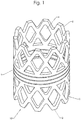
- the Fig. 1 shows a perspective view of a first embodiment of an implant according to the invention in the form of a placeholder for vertebrae or intervertebral discs.
- the placeholder 10 has a cylindrical body 1 and two frontally provided on the cylindrical body 1 connecting elements 2 for connecting the placeholder 10 with adjacent body parts, z.
- bone or cartilage in, for example, a human body on.
- the connecting elements 2, which are arranged at the front ends of the cylindrical body 1, are identical in the embodiment shown, but may also be designed differently.
- the connecting elements 2 have at their ends again at each of the free end teeth 3, which can engage in the adjacent body tissue at the implantation site.
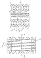
- the prongs 3 are formed by triangular recesses 5 on the two end faces of the spacer 10, so that form trapezoidal prongs 3, which engage in adjacent body tissue and can dig into it.
- connecting elements 2 diamond-shaped recesses 4 (see Fig. 2 ), which are provided adjacent to each other around the entire cylinder surface of the connecting elements 2.
- the respective connecting element is formed on its own again by a plurality of diamond-shaped interconnected webs 6, wherein the tips of the diamonds formed by the webs 6 are cut to form the trapezoidal serrations 3.
- the cylindrical tube-like body 1 between the connecting elements 2 at the respective end faces of the cylinder has in the embodiment shown a spiral material recess 7, so that the wall 11 (see Fig. 3 ) itself assumes a spiral shape.
- the cylindrical tube-like body 1 between the connecting elements 2 with the material recess 7 is an elastic region or a range of motion, even if the placeholder 10 itself consists of a substantially rigid material such. As titanium or a titanium alloy is formed. Due to the material recess 7 of the placeholder 10 receives a design-related elasticity in the region of the cylindrical tube-like body 1, which makes it unnecessary to provide a separate elastic material in this area to achieve a certain elasticity or mobility. In particular, it can thus be avoided to have to produce the placeholder from several parts to be joined together.
- spiral material recess 7 is in a simple manner a distensibility and compressibility of the cylinder tube-like body 1 along the longitudinal axis 9 of the spacer 10 and a bendability about a rotation axis perpendicular to the longitudinal axis 9, which is illustrated for example by the axis 8 ( Fig. 2 ), reached.
- the spiral shape of the material recess has proven 7, which allows a balanced elasticity and mobility in different directions.
- other forms of material recesses and a different number and arrangement of these material recesses are possible and conceivable, with the individual case or the load profile of the case adapted solutions are possible.
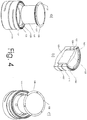
- the Fig. 4 shows in the partial images a) to c) three different perspective exploded views and sectional views (b) of a second embodiment of a placeholder 100 with a cylindrical tube-like body 101 which is closed at the bottom by an integrally connected to the cylinder tube-like body 101 end plate 125, so that a cup-like shape results.
- the cylindrical tube-like body 101 has, in its wall 111, a spiral-shaped recess 107 which, according to the invention, gives the cylindrical tube-like body 101 a certain flexibility.
- an exchangeable core member 130 made of an elastomeric material is provided in the cylindrical tube-like body 101, which is held at the bottom via the end plate 125 and at the top via the end plate 126 in the cylindrical tube-like body 101 ,
- the end plate 126 at the top of the placeholder has an external thread 127, by means of which it can be screwed into the internal thread 128 of the cylinder tube-like body 101 at the upper end face in the inside of the cylinder tube-like body 101.
- the end plate 126 has a shoulder with which it rests tightly on the wall 111.
- Surrounding the teeth 111 are provided on the wall 111 on the front side, which protrude beyond the end plates 125 and 126 and can engage in the adjacent tissue, so as to hold the placeholder in place.
- the end plate 126 has engagement openings 129, by means of which the end plate 126 can be screwed into the cylinder tube-like body 101.
- the end plates 125 and 126 may also be roughened on the outside or bio-coated to promote ingrowth.
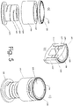
- the Fig. 5 shows in the sub-images a) to c), a third embodiment of a placeholder, wherein the partial images a) to c) represent perspective exploded views, while partial image b) shows a perspective sectional view.
- the cylindrical tube-like body 201 in turn has a helical recess 207 in the body wall 211.
- the end plate 225 is formed to have a larger outer diameter than the cylindrical tube-like body 201 in which the spiral material recess 207 is disposed.
- a shoulder is formed which forms a receptacle for a tubular sleeve 230 of elastomeric material. The elastic sleeve 230 is pushed over the cylindrical tube-like body 201, so that it is completely surrounded by the sleeve.
- an end plate 226 is screwed to the cylindrical tube-like body 201 by means of a threaded connection.
- the external thread 227 of the end plate 226 engages with the internal thread 228 of the cylinder tube-like body 201, so that the sleeve 230 is held between the end plates 225 and 226.
- the sleeve 230 also serves to adjust the overall rigidity, by simply replacing the sleeve 230 in a manner similar to replacing the core 130 (see FIG Fig. 4 ) a simple variation of the rigidity of the total implant 100 or 200 is possible.
- pyramidal teeth 203 are provided, which serve to engage in the adjacent tissue so as to firmly anchor the placeholder.
- the end plates 225 and 226 can also be roughened or bioactively coated on at least their outer sides.
- the lid 226 has engagement openings 229, by means of which the end plate 226 can be screwed onto the cylinder tube-like body 201.
Description
Die Erfindung betrifft einen flexiblen Platzhalter nach dem Oberbegriff des Anspruchs 1.The invention relates to a flexible placeholder according to the preamble of claim 1.
In der modernen Medizin können viele Defekte am menschlichen oder tierischen Körper durch den Einsatz von Implantaten ausgeglichen oder in ihren Wirkungen minimiert werden. Beispielsweise sind Platzhalter für Wirbel oder Bandscheiben bekannt, die zum Ersatz eines Wirbelkörpers oder einer Bandscheibe dienen.In modern medicine, many defects in the human or animal body can be compensated by the use of implants or minimized in their effects. For example, placeholders for vertebrae or discs are known, which serve to replace a vertebral body or an intervertebral disc.
Bei den Platzhaltern kommt es darauf an, dass Werkstoffe zum Einsatz kommen, die mit dem menschlichen oder tierischen Organismus verträglich sind, also keine Abstoßreaktionen hervorrufen oder durch Auflösungserscheinungen zu einer Belastung des Organismus führen. Entsprechend ist die Auswahl an Werkstoffen für Platzhalter deutlich eingeschränkt.With the placeholders, it is important that materials are used that are compatible with the human or animal organism, ie cause no repulsive reactions or lead by disintegration to a load on the organism. Accordingly, the choice of materials for placeholders is clearly limited.
Darüber hinaus ist es vorteilhaft, die Platzhalter möglichst einfach und insbesondere aus wenigen Teilen zu bilden, da das Zusammensetzen der Teile einen erhöhten Aufwand für den Operateur beim Einsetzen der Implantate begründet und zum anderen durch die Verbindungsstellen der einzelnen Teile zueinander eine größere Fehleranfälligkeit und damit Wahrscheinlichkeit für Fehlfunktionen gegeben ist. Insofern ist es besonders bevorzugt, Platzhalter einstückig auszubilden.In addition, it is advantageous to form the placeholder as simple as possible and in particular from a few parts, since the assembly of parts an increased effort for the surgeon when inserting the implants justified and on the other by the connection points of the individual parts to each other a greater susceptibility to errors and thus probability is given for malfunctions. In this respect, it is particularly preferred to form wildcards in one piece.
Demgegenüber müssen Platzhalter jedoch unterschiedliche Funktionen erfüllen, die es wünschenswert erscheinen lassen, unterschiedliche Werkstoffe einzusetzen und/oder Platzhalter aus mehreren Bauteilen zusammenzusetzen. Beispielsweise ist es für Platzhalter erstrebenswert, dass sie nicht nur die Funktion des Ausfüllens des Platzes und Haltens der Wirbel in einem bestimmten Abstand zueinander erfüllen, sondern dass sie darüber hinaus eine gewisse Beweglichkeit der Wirbel zueinander ermöglichen, also in gewissen engen Grenzen eine Gelenkfunktion ausfüllen. Zu diesem Zweck ist es beispielsweise möglich, einen Platzhalter gemäß der
Aus den Dokumenten
Es ist deshalb Aufgabe der vorliegenden Erfindung, Platzhalter bereitzustellen, die möglichst einfach, insbesondere einstückig oder aus wenigen einfach zu verbindenden Teilen aufgebaut sind und bei denen neben der Platzhalter- und Gewichtsübertragungsfunktion eine gewisse Flexibilität und Beweglichkeit innerhalb des Platzhalters bzw. Bereichen davon gewährleistet werden soll. Darüber hinaus sollen diese Platzhalter einfach herstellbar und implantierbar und sicher im Betrieb sein sowie eine lange Lebensdauer aufweisen.It is therefore an object of the present invention to provide wildcards that are as simple as possible, especially in one piece or constructed from a few easy-to-connect parts and where in addition to the placeholder and weight transfer function a certain flexibility and flexibility within the wildcard or areas thereof should be guaranteed , In addition, these wildcards are easy to manufacture and implantable and safe to operate and have a long life.
Diese Aufgabe wird gelöst durch Platzhalter mit den Merkmalen gemäß Anspruch 1. Vorteilhafte Ausgestaltungen sind Gegenstand der abhängigen Ansprüche.This object is achieved by wildcards having the features according to claim 1. Advantageous embodiments are the subject of the dependent claims.
Bei den Platzhaltern wird nach dem Stand der Technik die Beweglichkeit oder Elastizität durch zusätzliche Bauteile oder Werkstoffe erreicht. Die Erfindung geht hierbei einen anderen Weg, indem die Flexibilität bzw. Beweglichkeit primär nicht durch einen anderen Werkstoff oder durch das Vorsehen von zusätzlichen getrennten Bauteilen bewirkt wird, sondern dass dies durch das konstruktive Vorsehen von Materialaussparungen erreicht wird.In the placeholders, the mobility or elasticity is achieved by additional components or materials according to the prior art. The invention takes a different approach in that the flexibility or mobility is not primarily caused by another material or by the provision of additional separate components, but that this is achieved by the structural provision of material recesses.
Erfindungsgemäß weisen die Platzhalter einen zylinderrohrartigen Körper mit einem mittleren zylinderrohrartigen Körperteil sowie an den Stirnseiten vorgesehene Verbindungselemente auf, wobei die für die Flexibilität verantwortlichen Materialaussparungen im zylinderrohrartigen Körperteil vorgesehen sind.According to the invention, the placeholders have a cylindrical tube-like body with a central cylindrical tube-like body part and connecting elements provided on the end faces, the material recesses responsible for the flexibility being provided in the cylindrical tube-like body part.
Die Verbindungselemente der Platzhalter weisen vorzugsweise entsprechende Mittel zum Verbinden des Platzhalters mit benachbarten Körperteilen, wie z. B. Wirbeln, in Form von zackenartigen Vorsprüngen an den Stirnseiten und/oder Aussparungen, Vertiefungen und Öffnungen an der Mantelfläche zum Einwachsen und Verwachsen des Platzhalters mit dem Gewebe auf. Hierbei dürfen jedoch die Aussparungen oder Vertiefungen der Verbindungselemente nicht mit den Materialaussparungen zur Erzielung einer Flexibilität und Beweglichkeit des Platzhalters im zylinderrohrartigen Körperteil verwechselt werden. Da die Verbindungselemente mit den benachbarten Körperteilen, wie den Wirbeln, vollständig verwachsen, tragen diese nichts zur Flexibilität bzw. Beweglichkeit der Wirbel zueinander bei.The connection elements of the placeholders preferably have corresponding means for connecting the placeholder with adjacent body parts, such. As whirling, in the form of serrated projections on the end faces and / or recesses, recesses and openings on the lateral surface for ingrowth and ingrowth of the placeholder with the tissue. In this case, however, the recesses or depressions of the connecting elements must not be confused with the material recesses to achieve flexibility and flexibility of the placeholder in the cylinder tube-like body part. Since the connecting elements with the adjacent body parts, such as the vertebrae, completely fused, they contribute nothing to the flexibility or mobility of the vertebrae to each other.
Auf die erfindungsgemäße Weise kann in einfacher Weise bei Verzicht auf zusätzliche elastische Werkstoffe und entsprechende Verbindungsstellen oder zusätzliche getrennte Bauteile eine Flexibilität und Beweglichkeit innerhalb des Platzhalters oder Teilen davon erreicht werden. Hierbei können die Elastizitäts- oder Beweglichkeitsfunktionen zusätzlich zu den notwendigen Funktionen des Platzhalters vorgesehen werden. Insbesondere können auf diese Weise Kompressions-, Torsions- und/oder Dehnzonen in einfacher und zuverlässiger Weise insbesondere in einem einstückigen Platzhalter verwirklicht werden.In the manner according to the invention, a flexibility and flexibility within the placeholder or parts thereof can be achieved in a simple manner without the need for additional elastic materials and corresponding connection points or additional separate components. In this case, the elasticity or mobility functions can be provided in addition to the necessary functions of the placeholder. In particular, in this way compression, torsion and / or expansion zones can be realized in a simple and reliable manner, in particular in a one-piece placeholder.
Entsprechend kann für den vorzugsweise einstückig gebildeten Platzhalter ein stabiler fester, insbesondere bei den vorgesehenen Einsatzbedingungen steifer, vorzugsweise biegesteifer Werkstoff wie beispielsweise Titan, Titanlegierungen, Kunststoffe oder dgl. eingesetzt werden. Allgemein kommen alle biokompatiblen Werkstoffe in Frage, die keine Abstoßreaktionen hervorrufen oder für den Körper belastende Auflösungserscheinungen zeigen.Accordingly, for the preferably integrally formed placeholder a stable solid, especially in the intended conditions of use stiffer, preferably rigid material such as titanium, titanium alloys, plastics or the like. Be used. In general, all biocompatible materials come into question, which cause no repulsive reactions or show stressful for the body dissolution phenomena.
Die Materialaussparungen können vorzugsweise in Form von nutenförmigen Vertiefungen oder offenen Durchbrechungen im zylinderrohrartigen Körperteil vorgesehen werden. Die Form, Anzahl und Anordnung der Materialaussparungen kann im Einzelfall auf die Beanspruchungsanforderungen angepasst werden.The material recesses may preferably be provided in the form of groove-shaped recesses or open openings in the cylinder tube-like body part. The shape, number and arrangement of the material recesses can be adapted in individual cases to the requirements of the load.
Als eine universelle Form, die vielfältigen Anspruchsanforderungen genügt, kann die Materialaussparung insbesondere spiralförmig umlaufend um den zylinderrohrartigen Körper vorgesehen sein, so dass sich insbesondere die Form einer Art Schraubenfeder ergibt, wobei hier insbesondere vorteilhaft ist, dass durch die Materialaussparung Freiräume zwischen benachbarten Stegen des Schraubenfederelements vorliegen. Dies hat neben der leichteren Herstellbarkeit und der damit verbundenen größeren Materialauswahl auch den Vorteil, dass eine größere Flexibilität erreicht wird.As a universal shape that satisfies a wide variety of requirements, the material recess can be provided in particular in a spiral around the cylindrical tube-like body, so that in particular the shape of a kind of coil spring results, wherein it is particularly advantageous that free space between adjacent webs of the coil spring element by the material recess available. This has in addition to the ease of manufacture and the associated greater choice of materials and the advantage that greater flexibility is achieved.
Besonders vorteilhaft können zwei Materialaussparungen vorgesehen werden, die doppelläufig bzw. 2-gängig spiralförmig ausgebildet sind. Auf diese Weise können insbesondere zwei ineinander angeordnete Schraubenfedern gebildet werden. Bei gleicher Höhe des Bereichs der spiralförmigen Aussparung können so statt einer spiralförmigen Aussparung mit niedriger Steigung zwei spiralförmige Aussparungen mit doppelter Steigung vorgesehen werden.Particularly advantageous two material recesses can be provided, which are double-barreled or 2-course spirally formed. In this way, in particular two mutually arranged coil springs can be formed. For the same height of the area of the spiral-shaped recess, it is thus possible to provide two spiral pitches with double pitch instead of a spiral pitch with a low pitch.
Die Mittel zum Verbinden des zylinderrohrartigen Körpers mit benachbarten Körperteilen können entweder einstückig mit dem zylinderrohrartigen Körper insbesondere in Verlängerung dieses Körpers an den Stirnseiten oder lösbar an den Stirnseiten angeordnet sein, wie z. B. an Endplatten, die an den Stirnseiten des zylinderrohrartigen Körpers aufgeschraubt werden können.The means for connecting the cylinder tube-like body with adjacent body parts may be arranged either integrally with the cylinder tube-like body, in particular in extension of this body at the end faces or detachably at the end faces, such. B. to end plates that can be screwed to the front sides of the cylindrical tube-like body.
Derartige abnehmbare oder einstückig mit dem zylinderrohrartigen Körper verbundene Endplatten sind vorzugsweise dann vorgesehen, wenn um den zylinderrohrartigen Körper mit den Materialaussparungen zur Erzielung der Elastizität bzw. Beweglichkeit mindestens eine Hülse aus elastischem Material angeordnet ist oder innerhalb des zylinderrohrartigen Körpers mindestens ein elastischer Kern vorgesehen ist. Ein derartiger elastischer Kern oder eine elastische Hülse aus vorzugsweise einem Elastomer bietet den Vorteil, dass damit die Elastizität bzw. Steifigkeit des zylinderrohrartigen Körpers bzw. Platzhalters genau abgestimmt werden kann. Durch die modulartige Anordnung aus zylinderrohrartigem Körper mit entsprechenden Ausnehmungen sowie Kern und/oder Hülse kann durch Verwendung unterschiedlicher Komponenten mit verschiedenen Steifigkeiten in einfacher Weise eine exakt definierte Steifigkeit im Sinne von Dämpfung des Platzhalters eingestellt werden. Insofern ist ganz allgemein eine Kombination eines Platzhalterteils mit Materialaussparungen zur Erzielung einer Flexibilität und eines aus einem flexiblen Material bestehenden Platzhalterteils zur Einstellung einer definierten Steifigkeit Gegenstand der vorliegenden Erfindung. Zur Erzielung einer veränderten Steifigkeit muss lediglich die Zusammenstellung der Komponenten verändert werden, also beispielsweise muss ein anderer Kern mit einer anderen Steifigkeit oder eine andere Hülse mit dem flexiblen zylinderrohrartigen Körper verwendet werden. Obwohl es denkbar ist, gleichzeitig eine Hülse und einen Kern zusammen mit einem flexiblen zylinderrohrartigen Körper einzusetzen, wird es der Einfachheit halber meist nur eine Kombination aus zylinderrohrartigem Körper und Kern oder zylinderrohrartigem Körper und Hülse sein. Die Hülse bietet hierbei noch den Vorteil, dass sie den zylinderrohrartigen Körper mit den vorzugsweise spiralförmigen Aussparungen vor äußeren Einflüssen schützt, während dem gegenüber beim Einsatz eines Kerns dieser durch den zylinderrohrartigen Körper geschützt ist.Such removable or integrally connected to the cylinder tube-like body end plates are preferably provided when at least one sleeve of elastic material is arranged around the cylinder tube-like body with the material recesses to achieve the elasticity or mobility or at least one elastic core is provided within the cylinder tube-like body. Such an elastic core or an elastic sleeve made of preferably an elastomer offers the advantage that the elasticity or rigidity of the cylinder tube-like body or spacer can be precisely matched. Due to the modular arrangement of cylinder tube-like body with corresponding recesses and core and / or sleeve can be adjusted by using different components with different stiffness in a simple manner a precisely defined stiffness in the sense of damping the placeholder. In this respect, a combination of a placeholder part with material recesses for achieving flexibility and a placeholder part consisting of a flexible material for setting a defined rigidity is quite generally the subject of the present invention. To achieve a changed rigidity, only the composition of the components has to be changed, for example, another core with a different stiffness or another sleeve with the flexible cylinder tube-like body has to be used. Although it is conceivable to use a sleeve and a core together with a flexible cylinder tube-like body at the same time, for the sake of simplicity it will usually be only a combination of cylinder-tube-like body and core or cylindrical tube-like body and sleeve. The sleeve here still has the advantage that it protects the cylinder tube-like body with the preferably spiral-shaped recesses against external influences, while the opposite when using a core this is protected by the cylinder tube-like body.
Sowohl Kern als auch Hülse können in vorteilhafter Weise durch die Anordnung von Endplatten an den Stirnseiten des zylinderrohrartigen Körpers gehalten werden, wobei im Falle der Anordnung einer Hülse die Endplatten über den zylinderrohrartigen Körper hinausstehen müssen und somit einen größeren Durchmesser aufweisen als der zylinderrohrartige Körper. Die Endplatten können zumindest teilweise, also auf einer Seite einstückig mit dem zylinderrohrartigem Körper verbunden sein, so dass sich hier eine becherartige Form ergibt. Darüber hinaus können die Endplatten entweder einseitig oder zweiseitig, lösbar mit dem zylinderrohrartigen Körper verbunden sein, beispielsweise über eine Schraub- oder Gewindeverbindung. Hierbei kann das Außengewinde sowohl an der Endplatte als auch am zylinderrohrartigen Körper vorgesehen sein.Both core and sleeve can be kept in an advantageous manner by the arrangement of end plates on the end faces of the cylinder tube-like body, wherein in Case of the arrangement of a sleeve, the end plates must protrude beyond the cylinder tube-like body and thus have a larger diameter than the cylindrical tube-like body. The end plates can be at least partially, so connected on one side in one piece with the zylinderrohrartigem body, so that here results in a cup-like shape. In addition, the end plates can be connected to the cylindrical tube-like body either on one side or on both sides, detachably, for example via a screwed or threaded connection. In this case, the external thread can be provided both on the end plate and on the cylinder tube-like body.
Vorzugsweise ist der Platzhalter bzw. der zylinderrohrartige Körper mit den Materialaussparungen zur Erzielung von Flexibilität und Beweglichkeit in seiner Längsrichtung entlang der Platzhalterlängsachse um 0,5 bis 20 %, insbesondere 1 bis 15 % dehn- oder komprimierbar, und um eine radiale Achse senkrecht zur Platzhalterlängsachse bzw. um die Platzhalterlängsachse biegbar bzw. tordierbar, so dass die benachbarten Körperteile um ca. 0,5° bis 10°, insbesondere 1° bis 6° Grad bezüglich der Längsachse verschwenkbar oder um 0,5° bis 5° tordierbar sind.Preferably, the placeholder or the cylindrical tube-like body with the material recesses for achieving flexibility and flexibility in its longitudinal direction along the Platzhalterlängsachse by 0.5 to 20%, in particular 1 to 15% expandable or compressible, and about a radial axis perpendicular to the Platzhalterlängsachse or about the Platzhalterlängsachse bendable or twistable, so that the adjacent body parts are pivotable about 0.5 ° to 10 °, in particular 1 ° to 6 ° degrees with respect to the longitudinal axis or by 0.5 ° to 5 ° twisted.
Weitere Vorteile, Kennzeichen und Merkmale der vorliegenden Erfindung werden bei der nachfolgenden detaillierten Beschreibung zweier Ausführungsbeispiele an Hand der beigefügten Zeichnungen deutlich. Die Zeichnungen zeigen dabei in rein schematischer Weise in
- Fig. 1
- eine perspektivische Ansicht eines Platzhalters für Wirbel oder Bandscheiben;
- Fig. 2
- eine Seitenansicht des Platzhalters aus
Fig. 1 ; - Fig. 3
- eine detaillierte Seitenansicht des Platzhalters aus den
Fig. 1 und2 ; - Fig. 4 a) - c)
- Ansichten eines weiteren Platzhalters; und in
- Fig. 5 a) - c)
- Ansichten eines dritten Platzhalters.
- Fig. 1
- a perspective view of a placeholder for vertebrae or discs;
- Fig. 2
- a side view of the placeholder
Fig. 1 ; - Fig. 3
- a detailed side view of the placeholder from the
Fig. 1 and2 ; - Fig. 4 a) - c)
- Views of another placeholder; and in
- Fig. 5 a) - c)
- Views of a third placeholder.
Die
Die Verbindungselemente 2, die an den stirnseitigen Enden des zylinderförmigen Körpers 1 angeordnet sind, sind in dem gezeigten Ausführungsbeispiel identisch ausgebildet, können jedoch auch unterschiedlich ausgebildet sein. Die Verbindungselemente 2 weisen an ihren Stirnseiten wieder jeweils am freien Ende Zacken 3 auf, die in das benachbarte Körpergewebe am Implantationsort eingreifen können.The connecting
Die Zacken 3 sind durch dreieckförmige Ausnehmungen 5 an den beiden Stirnseiten des Platzhalters 10 gebildet, so dass sich trapezförmige Zacken 3 bilden, die in benachbartes Körpergewebe eingreifen und sich mit diesem verkrallen können.The prongs 3 are formed by triangular recesses 5 on the two end faces of the
Darüber hinaus weisen die Verbindungselemente 2 rautenförmige Ausnehmungen 4 auf (siehe
Der zylinderrohrartige Körper 1 zwischen den Verbindungselementen 2 an den jeweiligen Stirnseiten des Zylinders weist in dem gezeigten Ausführungsbeispiel eine spiralförmige Materialaussparung 7 auf, so dass die Wandung 11 (siehe
Durch die spiralförmige Materialaussparung 7 wird in einfacher Weise eine Dehnbarkeit und Kompressibilität des zylinderrohrartigen Körpers 1 entlang der Längsachse 9 des Platzhalters 10 sowie eine Biegbarkeit um eine Drehachse senkrecht zur Längsachse 9, welche beispielsweise durch die Achse 8 verdeutlicht ist (
Die
Der zylinderrohrartige Körper 101 weist in seiner Wandung 111 eine spiralförmig verlaufende Ausnehmung 107 auf, die dem zylinderrohrartigen Körper 101 erfindungsgemäß eine gewisse Flexibilität verleiht.The cylindrical tube-
Um die Steifigkeit des Platzhalters 100 genau anpassen zu können, ist in dem zylinderrohrartigen Körper 101 ein austauschbares Kernelement 130 aus einem elastomeren Werkstoff vorgesehen, welches an der Unterseite über die Endplatte 125 und an der Oberseite über die Endplatte 126 in dem zylinderrohrartigen Körper 101 gehalten ist.In order to be able to precisely adjust the rigidity of the
Die Endplatte 126 an der Oberseite des Platzhalters weist ein Außengewinde 127 auf, mittels dem es in das Innengewinde 128 des zylinderrohrartigen Körpers 101 an der oberen Stirnfläche in der Innenseite des zylinderrohrartigen Körpers 101 eingeschraubt werden kann. Die Endplatte 126 weist eine Schulter auf, mit der sie auf der Wandung 111 dicht aufliegt. Umlaufend sind an der Stirnseite an der Wandung 111 Zacken 103 vorgesehen, die über die Endplatten 125 und 126 hervorstehen und in das benachbarte Gewebe eingreifen können, um somit den Platzhalter an Ort und Stelle festzuhalten.The
Die Endplatte 126 weist Eingriffsöffnungen 129 auf, mittels der die Endplatte 126 in den zylinderrohrartigen Körper 101 eingeschraubt werden kann. Die Endplatten 125 und 126 können zudem an der Außenseite aufgerauht oder bioaktiv beschichtet sein, so dass das Einwachsen unterstützt wird.The
Die
An der Unterseite ist der zylinderrohrartige Körper 201 wieder über eine einstückig angeordnete Endplatte 225 verschlossen, so dass sich auch hier eine becherartige Form des zylinderrohrartigen Körpers 201 ergibt. Allerdings ist die Endplatte 225 so ausgebildet, dass sie einen größeren Außendurchmesser aufweist als der zylinderrohrartige Körper 201, in dem die spiralförmige Materialausnehmung 207 angeordnet ist. Somit entsteht eine Schulter, die eine Aufnahme für eine rohrartige Hülse 230 aus Elastomermaterial bildet. Die elastische Hülse 230 wird über den zylinderrohrartigen Körper 201 geschoben, so dass dieser vollständig von der Hülse umgeben ist. An der oberen Stirnfläche wird eine Endplatte 226 mittels einer Gewindeverbindung an den zylinderrohrartigen Körper 201 angeschraubt. Hierbei greift das Außengewinde 227 der Endplatte 226 in das Innengewinde 228 des zylinderrohrartigen Körpers 201 ein, so dass die Hülse 230 zwischen den Endplatten 225 und 226 festgehalten wird. Auch die Hülse 230 dient zur Anpassung der Gesamtsteifigkeit, wobei durch ein einfaches Auswechseln der Hülse 230 in ähnlicher Weise wie durch ein Austauschen des Kerns 130 (siehe
An den Endplatten 226 bzw. 225 sind pyramidenförmige Zacken 203 vorgesehen, die zum Eingreifen in das benachbarte Gewebe dienen, um so den Platzhalter fest zu verankern. Auch die Endplatten 225 und 226 können zumindest an ihren Außenseiten aufgerauht oder bioaktiv beschichtet sein.At the
Auch der Deckel 226 weist Eingriffsöffnungen 229 auf, mittels derer die Endplatte 226 auf den zylinderrohrartigen Körper 201 aufgeschraubt werden kann.Also, the
Claims (11)
- A space holder for vertebrae and/or intervertebral discs with space-holding and weight-transfer function for temporary or permanent introduction into a human or animal body and made from at least one biocompatible material having a tube-like body (1) and having, on the end-faces of the tube-like body, means (2) for connecting to adjacent body parts wherein the tube-like body has recesses to locally reduce the rigidity, wherein the tube-like body (1) is surrounded by a sleeve made from an elastomer and/or is provided with a core made from an elastomer, which are held by end plates which are disposed monolithically and/or detachably, especially by means of a screw or threaded connection, on the tube-like body and which cooperate with the tube-like body with recesses for the purpose of achieving flexibility, such that the desired frigidity or mobility of the overall implant can be adjusted, such that the space holder is compressible and extensible in the axial direction and, with respect to the means (2) provided on the end-faces for the purpose of connecting the space holder to adjacent body parts, can be bent about a radial rotational axis (13) and twisted about an axial rotational axis.
- Space holder in accordance with claim 1,
characterised in that
the tube-like body and the means for connecting to adjacent body parts are formed monolithically from one material. - Space holder in accordance with any of the preceding claims
characterised in that
the biocompatible material, especially of the tube-like body, is made from a material which is stiff, especially rigid, in the intended application conditions. - Space holder in accordance with any of the preceding claims
characterised in that
the biocompatible material is selected from the group comprising titanium, titanium alloys, and polymers. - Space holder in accordance with any of the preceding claims,
characterised in that
the recess (7, 19) is a groove and/or an open aperture, and especially is helical. - Space holder in accordance with any of the preceding claims,
characterised in that
two recesses as a groove-like depression and/or as an open aperture are arranged in a double-helix in each other. - Space holder in accordance with any of the preceding claims,
characterised in that
the means (2) for connecting the tube-like body to adjacent body parts have projections (3), especially serrations (3) extending in the axial direction of the tube-like body with especially a triangular and/or trapezoidal shape for the purpose of penetrating into adjacent body parts, especially bones, cartilage and the like. - Space holder in accordance with any of the preceding claims,
characterised in that
the means (2) for connecting the tube-like body to adjacent body parts are formed as a preferably monolithic extension of the tube-like body (1), wherein depressions, openings and/or recesses (4) are disposed in the lateral surface for the purpose of in-growth. - Space holder in accordance with any of the preceding claims,
characterised in that
the means (2) for connecting the tube-like body to adjacent body parts are disposed on an end plate which is detachably disposed on the end-face of the tube-like body. - Space holder in accordance with any of the preceding claims,
characterised in that
the space holder and especially the tube-like body is elastically extensible or compressible by 0.5 to 20%, especially 1 to 15%, with respect to its longitudinal direction. - Space holder in accordance with any of the preceding claims,
characterised in that
the space holder and especially the tube-like body (1) are elastically bendable about a radial axis (3), such that the means (2) provided on the end-faces for the purpose of connecting to adjacent body parts can be pivoted by approx. 0.5° to 10°, especially 1° to 6°, out of the longitudinal axis (12) of the tube-like body or that the space holder and especially the tube-like body can be twisted elastically about an axial axis, such that the means (2) provided on the end faces for connecting to adjacent body parts can be rotated by approx. 0.5° to 5°, especially 1° to 3°.
Priority Applications (1)
| Application Number | Priority Date | Filing Date | Title |
|---|---|---|---|
| EP08103566.9A EP1949872B1 (en) | 2004-05-04 | 2005-05-04 | Flexible spacer |
Applications Claiming Priority (4)
| Application Number | Priority Date | Filing Date | Title |
|---|---|---|---|
| US56798904P | 2004-05-04 | 2004-05-04 | |
| DE102004021861A DE102004021861A1 (en) | 2004-05-04 | 2004-05-04 | Implant for temporary or permanent replacement of vertebra or intervertebral disk, comprising solid central element and outer elements with openings |
| US567989P | 2004-05-04 | ||
| DE102004021861 | 2004-05-04 |
Related Child Applications (2)
| Application Number | Title | Priority Date | Filing Date |
|---|---|---|---|
| EP08103566.9A Division-Into EP1949872B1 (en) | 2004-05-04 | 2005-05-04 | Flexible spacer |
| EP08103566.9A Division EP1949872B1 (en) | 2004-05-04 | 2005-05-04 | Flexible spacer |
Publications (2)
| Publication Number | Publication Date |
|---|---|
| EP1593357A1 EP1593357A1 (en) | 2005-11-09 |
| EP1593357B1 true EP1593357B1 (en) | 2017-01-04 |
Family
ID=35219995
Family Applications (1)
| Application Number | Title | Priority Date | Filing Date |
|---|---|---|---|
| EP05009856.5A Not-in-force EP1593357B1 (en) | 2004-05-04 | 2005-05-04 | Flexible spacer |
Country Status (6)
| Country | Link |
|---|---|
| US (2) | US8771357B2 (en) |
| EP (1) | EP1593357B1 (en) |
| JP (1) | JP2005319303A (en) |
| CN (1) | CN100566670C (en) |
| DE (1) | DE102004021861A1 (en) |
| ES (2) | ES2619167T3 (en) |
Families Citing this family (129)
| Publication number | Priority date | Publication date | Assignee | Title |
|---|---|---|---|---|
| US7833250B2 (en) | 2004-11-10 | 2010-11-16 | Jackson Roger P | Polyaxial bone screw with helically wound capture connection |
| US8292926B2 (en) | 2005-09-30 | 2012-10-23 | Jackson Roger P | Dynamic stabilization connecting member with elastic core and outer sleeve |
| US10729469B2 (en) | 2006-01-09 | 2020-08-04 | Roger P. Jackson | Flexible spinal stabilization assembly with spacer having off-axis core member |
| US8353932B2 (en) | 2005-09-30 | 2013-01-15 | Jackson Roger P | Polyaxial bone anchor assembly with one-piece closure, pressure insert and plastic elongate member |
| US10258382B2 (en) | 2007-01-18 | 2019-04-16 | Roger P. Jackson | Rod-cord dynamic connection assemblies with slidable bone anchor attachment members along the cord |
| US7862587B2 (en) | 2004-02-27 | 2011-01-04 | Jackson Roger P | Dynamic stabilization assemblies, tool set and method |
| US8876868B2 (en) | 2002-09-06 | 2014-11-04 | Roger P. Jackson | Helical guide and advancement flange with radially loaded lip |
| MXPA05008653A (en) | 2003-02-14 | 2006-04-27 | Depuy Spine Inc | In-situ formed intervertebral fusion device and method. |
| US8540753B2 (en) | 2003-04-09 | 2013-09-24 | Roger P. Jackson | Polyaxial bone screw with uploaded threaded shank and method of assembly and use |
| US7621918B2 (en) | 2004-11-23 | 2009-11-24 | Jackson Roger P | Spinal fixation tool set and method |
| US7377923B2 (en) | 2003-05-22 | 2008-05-27 | Alphatec Spine, Inc. | Variable angle spinal screw assembly |
| US8366753B2 (en) | 2003-06-18 | 2013-02-05 | Jackson Roger P | Polyaxial bone screw assembly with fixed retaining structure |
| US7766915B2 (en) | 2004-02-27 | 2010-08-03 | Jackson Roger P | Dynamic fixation assemblies with inner core and outer coil-like member |
| US8092500B2 (en) | 2007-05-01 | 2012-01-10 | Jackson Roger P | Dynamic stabilization connecting member with floating core, compression spacer and over-mold |
| US7776067B2 (en) | 2005-05-27 | 2010-08-17 | Jackson Roger P | Polyaxial bone screw with shank articulation pressure insert and method |
| US8936623B2 (en) | 2003-06-18 | 2015-01-20 | Roger P. Jackson | Polyaxial bone screw assembly |
| US7967850B2 (en) | 2003-06-18 | 2011-06-28 | Jackson Roger P | Polyaxial bone anchor with helical capture connection, insert and dual locking assembly |
| DE10348329B3 (en) | 2003-10-17 | 2005-02-17 | Biedermann Motech Gmbh | Rod-shaped element used in spinal column and accident surgery for connecting two bone-anchoring elements comprises a rigid section and an elastic section that are made in one piece |
| US8632570B2 (en) | 2003-11-07 | 2014-01-21 | Biedermann Technologies Gmbh & Co. Kg | Stabilization device for bones comprising a spring element and manufacturing method for said spring element |
| US7179261B2 (en) | 2003-12-16 | 2007-02-20 | Depuy Spine, Inc. | Percutaneous access devices and bone anchor assemblies |
| US7527638B2 (en) | 2003-12-16 | 2009-05-05 | Depuy Spine, Inc. | Methods and devices for minimally invasive spinal fixation element placement |
| US11419642B2 (en) | 2003-12-16 | 2022-08-23 | Medos International Sarl | Percutaneous access devices and bone anchor assemblies |
| US7160300B2 (en) | 2004-02-27 | 2007-01-09 | Jackson Roger P | Orthopedic implant rod reduction tool set and method |
| US8152810B2 (en) | 2004-11-23 | 2012-04-10 | Jackson Roger P | Spinal fixation tool set and method |
| US11241261B2 (en) | 2005-09-30 | 2022-02-08 | Roger P Jackson | Apparatus and method for soft spinal stabilization using a tensionable cord and releasable end structure |
| AU2004317551B2 (en) | 2004-02-27 | 2008-12-04 | Roger P. Jackson | Orthopedic implant rod reduction tool set and method |
| US9050148B2 (en) | 2004-02-27 | 2015-06-09 | Roger P. Jackson | Spinal fixation tool attachment structure |
| US7651502B2 (en) | 2004-09-24 | 2010-01-26 | Jackson Roger P | Spinal fixation tool set and method for rod reduction and fastener insertion |
| EP1811911A4 (en) | 2004-11-10 | 2012-01-11 | Roger P Jackson | Helical guide and advancement flange with break-off extensions |
| US8926672B2 (en) | 2004-11-10 | 2015-01-06 | Roger P. Jackson | Splay control closure for open bone anchor |
| US9980753B2 (en) | 2009-06-15 | 2018-05-29 | Roger P Jackson | pivotal anchor with snap-in-place insert having rotation blocking extensions |
| US8444681B2 (en) | 2009-06-15 | 2013-05-21 | Roger P. Jackson | Polyaxial bone anchor with pop-on shank, friction fit retainer and winged insert |
| US9216041B2 (en) | 2009-06-15 | 2015-12-22 | Roger P. Jackson | Spinal connecting members with tensioned cords and rigid sleeves for engaging compression inserts |
| US9168069B2 (en) | 2009-06-15 | 2015-10-27 | Roger P. Jackson | Polyaxial bone anchor with pop-on shank and winged insert with lower skirt for engaging a friction fit retainer |
| ATE524121T1 (en) | 2004-11-24 | 2011-09-15 | Abdou Samy | DEVICES FOR PLACING AN ORTHOPEDIC INTERVERTEBRAL IMPLANT |
| US10076361B2 (en) | 2005-02-22 | 2018-09-18 | Roger P. Jackson | Polyaxial bone screw with spherical capture, compression and alignment and retention structures |
| US7901437B2 (en) | 2007-01-26 | 2011-03-08 | Jackson Roger P | Dynamic stabilization member with molded connection |
| EP1924227B1 (en) | 2005-08-16 | 2014-12-17 | Benvenue Medical, Inc. | Spinal tissue distraction devices |
| US8366773B2 (en) | 2005-08-16 | 2013-02-05 | Benvenue Medical, Inc. | Apparatus and method for treating bone |
| DE602005007223D1 (en) | 2005-08-24 | 2008-07-10 | Biedermann Motech Gmbh | Rod-shaped element for use in spine or trauma surgery and stabilization device with such an element |
| US8105368B2 (en) | 2005-09-30 | 2012-01-31 | Jackson Roger P | Dynamic stabilization connecting member with slitted core and outer sleeve |
| US7704271B2 (en) | 2005-12-19 | 2010-04-27 | Abdou M Samy | Devices and methods for inter-vertebral orthopedic device placement |
| US20070270821A1 (en) * | 2006-04-28 | 2007-11-22 | Sdgi Holdings, Inc. | Vertebral stabilizer |
| US7766942B2 (en) * | 2006-08-31 | 2010-08-03 | Warsaw Orthopedic, Inc. | Polymer rods for spinal applications |
| US20080140203A1 (en) * | 2006-10-24 | 2008-06-12 | Reginald Davis | Intervertebral disc support coil and screw applicator |
| US8105382B2 (en) | 2006-12-07 | 2012-01-31 | Interventional Spine, Inc. | Intervertebral implant |
| CA2670988C (en) | 2006-12-08 | 2014-03-25 | Roger P. Jackson | Tool system for dynamic spinal implants |
| US7875059B2 (en) | 2007-01-18 | 2011-01-25 | Warsaw Orthopedic, Inc. | Variable stiffness support members |
| US8475498B2 (en) | 2007-01-18 | 2013-07-02 | Roger P. Jackson | Dynamic stabilization connecting member with cord connection |
| US8366745B2 (en) | 2007-05-01 | 2013-02-05 | Jackson Roger P | Dynamic stabilization assembly having pre-compressed spacers with differential displacements |
| US8012177B2 (en) | 2007-02-12 | 2011-09-06 | Jackson Roger P | Dynamic stabilization assembly with frusto-conical connection |
| EP2124778B1 (en) | 2007-02-21 | 2019-09-25 | Benvenue Medical, Inc. | Devices for treating the spine |
| US8740944B2 (en) * | 2007-02-28 | 2014-06-03 | Warsaw Orthopedic, Inc. | Vertebral stabilizer |
| US10383660B2 (en) | 2007-05-01 | 2019-08-20 | Roger P. Jackson | Soft stabilization assemblies with pretensioned cords |
| CA2690038C (en) | 2007-05-31 | 2012-11-27 | Roger P. Jackson | Dynamic stabilization connecting member with pre-tensioned solid core |
| US8900307B2 (en) | 2007-06-26 | 2014-12-02 | DePuy Synthes Products, LLC | Highly lordosed fusion cage |
| WO2009055478A1 (en) * | 2007-10-22 | 2009-04-30 | Spinalmotion, Inc. | Vertebral body replacement and method for spanning a space formed upon removal of a vertebral body |
| US8911477B2 (en) | 2007-10-23 | 2014-12-16 | Roger P. Jackson | Dynamic stabilization member with end plate support and cable core extension |
| US9232968B2 (en) | 2007-12-19 | 2016-01-12 | DePuy Synthes Products, Inc. | Polymeric pedicle rods and methods of manufacturing |
| EP2471493A1 (en) | 2008-01-17 | 2012-07-04 | Synthes GmbH | An expandable intervertebral implant and associated method of manufacturing the same |
| KR20110003475A (en) | 2008-04-05 | 2011-01-12 | 신세스 게엠바하 | Expandable intervertebral implant |
| JP2012529969A (en) | 2008-08-01 | 2012-11-29 | ロジャー・ピー・ジャクソン | Longitudinal connecting member with tensioning cord with sleeve |
| US8641734B2 (en) | 2009-02-13 | 2014-02-04 | DePuy Synthes Products, LLC | Dual spring posterior dynamic stabilization device with elongation limiting elastomers |
| US9526620B2 (en) | 2009-03-30 | 2016-12-27 | DePuy Synthes Products, Inc. | Zero profile spinal fusion cage |
| US11229457B2 (en) | 2009-06-15 | 2022-01-25 | Roger P. Jackson | Pivotal bone anchor assembly with insert tool deployment |
| CN103917181A (en) | 2009-06-15 | 2014-07-09 | 罗杰.P.杰克逊 | Polyaxial bone anchor with pop-on shank and friction fit retainer with low profile edge lock |
| EP2757988A4 (en) | 2009-06-15 | 2015-08-19 | Jackson Roger P | Polyaxial bone anchor with pop-on shank and winged insert with friction fit compressive collet |
| US8998959B2 (en) | 2009-06-15 | 2015-04-07 | Roger P Jackson | Polyaxial bone anchors with pop-on shank, fully constrained friction fit retainer and lock and release insert |
| US9668771B2 (en) | 2009-06-15 | 2017-06-06 | Roger P Jackson | Soft stabilization assemblies with off-set connector |
| US9320543B2 (en) | 2009-06-25 | 2016-04-26 | DePuy Synthes Products, Inc. | Posterior dynamic stabilization device having a mobile anchor |
| WO2011043805A1 (en) | 2009-10-05 | 2011-04-14 | Roger Jackson P | Polyaxial bone anchor with non-pivotable retainer and pop-on shank, some with friction fit |
| US8764806B2 (en) | 2009-12-07 | 2014-07-01 | Samy Abdou | Devices and methods for minimally invasive spinal stabilization and instrumentation |
| US9393129B2 (en) | 2009-12-10 | 2016-07-19 | DePuy Synthes Products, Inc. | Bellows-like expandable interbody fusion cage |
| DE102010000339A1 (en) | 2010-02-08 | 2011-08-11 | Aesculap AG, 78532 | Connecting element for a spine stabilization system and spine stabilization system |
| US9445844B2 (en) | 2010-03-24 | 2016-09-20 | DePuy Synthes Products, Inc. | Composite material posterior dynamic stabilization spring rod |
| US8979860B2 (en) | 2010-06-24 | 2015-03-17 | DePuy Synthes Products. LLC | Enhanced cage insertion device |
| US9592063B2 (en) | 2010-06-24 | 2017-03-14 | DePuy Synthes Products, Inc. | Universal trial for lateral cages |
| TW201215379A (en) | 2010-06-29 | 2012-04-16 | Synthes Gmbh | Distractible intervertebral implant |
| EP2613719A1 (en) | 2010-09-08 | 2013-07-17 | Roger P. Jackson | Dynamic stabilization members with elastic and inelastic sections |
| US9402732B2 (en) | 2010-10-11 | 2016-08-02 | DePuy Synthes Products, Inc. | Expandable interspinous process spacer implant |
| DE112011103644T5 (en) | 2010-11-02 | 2013-12-24 | Roger P. Jackson | Polyaxial bone anchor with quick-release shaft and rotatable holder |
| US9700425B1 (en) | 2011-03-20 | 2017-07-11 | Nuvasive, Inc. | Vertebral body replacement and insertion methods |
| WO2012128825A1 (en) | 2011-03-24 | 2012-09-27 | Jackson Roger P | Polyaxial bone anchor with compound articulation and pop-on shank |
| US8845728B1 (en) | 2011-09-23 | 2014-09-30 | Samy Abdou | Spinal fixation devices and methods of use |
| TWI445523B (en) * | 2011-12-09 | 2014-07-21 | Metal Ind Res & Dev Ct | Cage-shaped spinal frame |
| US8696752B2 (en) * | 2011-12-30 | 2014-04-15 | Metal Industries Research & Development Centre | Interbody cage for spine fusion |
| US8911479B2 (en) | 2012-01-10 | 2014-12-16 | Roger P. Jackson | Multi-start closures for open implants |
| US20130226240A1 (en) | 2012-02-22 | 2013-08-29 | Samy Abdou | Spinous process fixation devices and methods of use |
| US9198767B2 (en) | 2012-08-28 | 2015-12-01 | Samy Abdou | Devices and methods for spinal stabilization and instrumentation |
| US9320617B2 (en) | 2012-10-22 | 2016-04-26 | Cogent Spine, LLC | Devices and methods for spinal stabilization and instrumentation |
| US8911478B2 (en) | 2012-11-21 | 2014-12-16 | Roger P. Jackson | Splay control closure for open bone anchor |
| US10058354B2 (en) | 2013-01-28 | 2018-08-28 | Roger P. Jackson | Pivotal bone anchor assembly with frictional shank head seating surfaces |
| US8852239B2 (en) | 2013-02-15 | 2014-10-07 | Roger P Jackson | Sagittal angle screw with integral shank and receiver |
| US9522070B2 (en) | 2013-03-07 | 2016-12-20 | Interventional Spine, Inc. | Intervertebral implant |
| US10085783B2 (en) | 2013-03-14 | 2018-10-02 | Izi Medical Products, Llc | Devices and methods for treating bone tissue |
| US9566092B2 (en) | 2013-10-29 | 2017-02-14 | Roger P. Jackson | Cervical bone anchor with collet retainer and outer locking sleeve |
| US9717533B2 (en) | 2013-12-12 | 2017-08-01 | Roger P. Jackson | Bone anchor closure pivot-splay control flange form guide and advancement structure |
| US9451993B2 (en) | 2014-01-09 | 2016-09-27 | Roger P. Jackson | Bi-radial pop-on cervical bone anchor |
| US10064658B2 (en) | 2014-06-04 | 2018-09-04 | Roger P. Jackson | Polyaxial bone anchor with insert guides |
| US9597119B2 (en) | 2014-06-04 | 2017-03-21 | Roger P. Jackson | Polyaxial bone anchor with polymer sleeve |
| US11426290B2 (en) | 2015-03-06 | 2022-08-30 | DePuy Synthes Products, Inc. | Expandable intervertebral implant, system, kit and method |
| US10492921B2 (en) | 2015-04-29 | 2019-12-03 | Institute for Musculoskeletal Science and Education, Ltd. | Implant with arched bone contacting elements |
| US9918849B2 (en) | 2015-04-29 | 2018-03-20 | Institute for Musculoskeletal Science and Education, Ltd. | Coiled implants and systems and methods of use thereof |
| US10709570B2 (en) | 2015-04-29 | 2020-07-14 | Institute for Musculoskeletal Science and Education, Ltd. | Implant with a diagonal insertion axis |
| US10449051B2 (en) | 2015-04-29 | 2019-10-22 | Institute for Musculoskeletal Science and Education, Ltd. | Implant with curved bone contacting elements |
| US10857003B1 (en) | 2015-10-14 | 2020-12-08 | Samy Abdou | Devices and methods for vertebral stabilization |
| EP4233801A3 (en) | 2016-06-28 | 2023-09-06 | Eit Emerging Implant Technologies GmbH | Expandable, angularly adjustable intervertebral cages |
| CN109688980B (en) | 2016-06-28 | 2022-06-10 | Eit 新兴移植技术股份有限公司 | Expandable and angularly adjustable intervertebral cage with articulation joint |
| US10973648B1 (en) | 2016-10-25 | 2021-04-13 | Samy Abdou | Devices and methods for vertebral bone realignment |
| US10478312B2 (en) | 2016-10-25 | 2019-11-19 | Institute for Musculoskeletal Science and Education, Ltd. | Implant with protected fusion zones |
| US10744000B1 (en) | 2016-10-25 | 2020-08-18 | Samy Abdou | Devices and methods for vertebral bone realignment |
| CN106344136B (en) * | 2016-11-24 | 2019-02-19 | 河南理工大学 | A kind of marrow support device |
| US10888433B2 (en) | 2016-12-14 | 2021-01-12 | DePuy Synthes Products, Inc. | Intervertebral implant inserter and related methods |
| US10512549B2 (en) | 2017-03-13 | 2019-12-24 | Institute for Musculoskeletal Science and Education, Ltd. | Implant with structural members arranged around a ring |
| US10357377B2 (en) | 2017-03-13 | 2019-07-23 | Institute for Musculoskeletal Science and Education, Ltd. | Implant with bone contacting elements having helical and undulating planar geometries |
| US10667924B2 (en) | 2017-03-13 | 2020-06-02 | Institute for Musculoskeletal Science and Education, Ltd. | Corpectomy implant |
| US10213317B2 (en) | 2017-03-13 | 2019-02-26 | Institute for Musculoskeletal Science and Education | Implant with supported helical members |
| US10398563B2 (en) | 2017-05-08 | 2019-09-03 | Medos International Sarl | Expandable cage |
| US11344424B2 (en) | 2017-06-14 | 2022-05-31 | Medos International Sarl | Expandable intervertebral implant and related methods |
| US10940016B2 (en) | 2017-07-05 | 2021-03-09 | Medos International Sarl | Expandable intervertebral fusion cage |
| US10940015B2 (en) | 2017-11-21 | 2021-03-09 | Institute for Musculoskeletal Science and Education, Ltd. | Implant with improved flow characteristics |
| US10744001B2 (en) | 2017-11-21 | 2020-08-18 | Institute for Musculoskeletal Science and Education, Ltd. | Implant with improved bone contact |
| US10695192B2 (en) | 2018-01-31 | 2020-06-30 | Institute for Musculoskeletal Science and Education, Ltd. | Implant with internal support members |
| US11179248B2 (en) | 2018-10-02 | 2021-11-23 | Samy Abdou | Devices and methods for spinal implantation |
| US11446156B2 (en) | 2018-10-25 | 2022-09-20 | Medos International Sarl | Expandable intervertebral implant, inserter instrument, and related methods |
| CN109966028B (en) * | 2019-04-28 | 2021-02-19 | 华南协同创新研究院 | Composite unit for bone implant, porous scaffold and preparation method |
| US11426286B2 (en) | 2020-03-06 | 2022-08-30 | Eit Emerging Implant Technologies Gmbh | Expandable intervertebral implant |
| US11850160B2 (en) | 2021-03-26 | 2023-12-26 | Medos International Sarl | Expandable lordotic intervertebral fusion cage |
| US11752009B2 (en) | 2021-04-06 | 2023-09-12 | Medos International Sarl | Expandable intervertebral fusion cage |
Citations (2)
| Publication number | Priority date | Publication date | Assignee | Title |
|---|---|---|---|---|
| DE20213013U1 (en) * | 2002-08-24 | 2002-12-19 | Metz Stavenhagen Peter | Spine wildcard |
| US6579321B1 (en) * | 1999-05-17 | 2003-06-17 | Vanderbilt University | Intervertebral disc replacement prosthesis |
Family Cites Families (107)
| Publication number | Priority date | Publication date | Assignee | Title |
|---|---|---|---|---|
| US1950448A (en) * | 1929-12-14 | 1934-03-13 | Charles A Heisterkamp | Flexible coupling |
| US4846839A (en) * | 1984-02-09 | 1989-07-11 | Joint Medical Products Corporation | Apparatus for affixing a prosthesis to bone |
| DE3637314A1 (en) * | 1986-11-03 | 1988-05-11 | Lutz Biedermann | SPACE HOLDER IMPLANT |
| DE8807485U1 (en) * | 1988-06-06 | 1989-08-10 | Mecron Medizinische Produkte Gmbh, 1000 Berlin, De | |
| US4911718A (en) | 1988-06-10 | 1990-03-27 | University Of Medicine & Dentistry Of N.J. | Functional and biocompatible intervertebral disc spacer |
| FR2634371A1 (en) | 1988-07-21 | 1990-01-26 | Flegeau Gerard | Hip prosthesis and method for manufacturing such a prosthesis |
| AU624627B2 (en) * | 1988-08-18 | 1992-06-18 | Johnson & Johnson Orthopaedics, Inc. | Functional and biocompatible intervertebral disc spacer containing elastomeric material of varying hardness |
| US4960420A (en) * | 1988-08-23 | 1990-10-02 | Marlowe Goble E | Channel ligament clamp and system |
| US4932975A (en) * | 1989-10-16 | 1990-06-12 | Vanderbilt University | Vertebral prosthesis |
| US5197488A (en) * | 1991-04-05 | 1993-03-30 | N. K. Biotechnical Engineering Co. | Knee joint load measuring instrument and joint prosthesis |
| JP2561401B2 (en) | 1991-07-05 | 1996-12-11 | 株式会社神戸製鋼所 | Metal artificial vertebral body |
| US5306307A (en) * | 1991-07-22 | 1994-04-26 | Calcitek, Inc. | Spinal disk implant |
| DE4128332A1 (en) * | 1991-08-27 | 1993-03-04 | Man Ceramics Gmbh | SPINE BONE REPLACEMENT |
| US5320644A (en) * | 1991-08-30 | 1994-06-14 | Sulzer Brothers Limited | Intervertebral disk prosthesis |
| JPH05277141A (en) * | 1992-03-30 | 1993-10-26 | Tokai Rubber Ind Ltd | Artificial intervertebral disk |
| EP0566810B1 (en) * | 1992-04-21 | 1996-08-14 | SULZER Medizinaltechnik AG | Artificial spinal disc |
| FR2692952B1 (en) * | 1992-06-25 | 1996-04-05 | Psi | IMPROVED SHOCK ABSORBER WITH MOVEMENT LIMIT. |
| DE4323034C1 (en) | 1993-07-09 | 1994-07-28 | Lutz Biedermann | Placeholders, especially for an intervertebral disc |
| US5423817A (en) * | 1993-07-29 | 1995-06-13 | Lin; Chih-I | Intervertebral fusing device |
| US5423816A (en) * | 1993-07-29 | 1995-06-13 | Lin; Chih I. | Intervertebral locking device |
| FR2709246B1 (en) * | 1993-08-27 | 1995-09-29 | Martin Jean Raymond | Dynamic implanted spinal orthosis. |
| FR2709949B1 (en) * | 1993-09-14 | 1995-10-13 | Commissariat Energie Atomique | Intervertebral disc prosthesis. |
| US5458642A (en) * | 1994-01-18 | 1995-10-17 | Beer; John C. | Synthetic intervertebral disc |
| ES2133517T3 (en) | 1994-02-28 | 1999-09-16 | Sulzer Orthopadie Ag | STABILIZER FOR ADJACENT VERTEBRAS. |
| EP0677277A3 (en) | 1994-03-18 | 1996-02-28 | Patrice Moreau | Spinal prosthetic assembly. |
| DE4409392A1 (en) | 1994-03-18 | 1995-09-21 | Biedermann Motech Gmbh | Adjustable vertebral body |
| FR2717370A1 (en) | 1994-03-18 | 1995-09-22 | Moreau Patrice | Intervertebral stabilising prosthesis for spinal reinforcement inserted during spinal surgery |
| DE4423257C2 (en) * | 1994-07-02 | 2001-07-12 | Ulrich Heinrich | Implant to be inserted between the vertebral body of the spine as a placeholder |
| WO1996017564A1 (en) * | 1994-12-09 | 1996-06-13 | Sofamor Danek Group, Inc. | Adjustable vertebral body replacement |
| DE19504867C1 (en) * | 1995-02-14 | 1996-02-29 | Harms Juergen | Position retainer for spine |
| DE19509317B4 (en) * | 1995-03-15 | 2006-08-10 | Heinrich Ulrich | Implant for insertion between vertebral bodies of the spine as a placeholder |
| FR2734148A1 (en) * | 1995-05-15 | 1996-11-22 | Biomat | Spinal intervertebral disc replacement prosthesis |
| DE19519101B4 (en) * | 1995-05-24 | 2009-04-23 | Harms, Jürgen, Prof. Dr. | Height adjustable vertebral body replacement |
| US5702449A (en) | 1995-06-07 | 1997-12-30 | Danek Medical, Inc. | Reinforced porous spinal implants |
| US6039762A (en) * | 1995-06-07 | 2000-03-21 | Sdgi Holdings, Inc. | Reinforced bone graft substitutes |
| DE19541114A1 (en) * | 1995-10-26 | 1997-04-30 | Artos Med Produkte | Intervertebral implant |
| US5683465A (en) * | 1996-03-18 | 1997-11-04 | Shinn; Gary Lee | Artificial intervertebral disk prosthesis |
| DE19622827B4 (en) * | 1996-06-07 | 2009-04-23 | Ulrich, Heinrich | Implant for insertion between vertebrae as a placeholder |
| US5702455A (en) * | 1996-07-03 | 1997-12-30 | Saggar; Rahul | Expandable prosthesis for spinal fusion |
| DE29616778U1 (en) * | 1996-09-26 | 1998-01-29 | Howmedica Gmbh | Vertebral body placeholder |
| US5782832A (en) * | 1996-10-01 | 1998-07-21 | Surgical Dynamics, Inc. | Spinal fusion implant and method of insertion thereof |
| US5897556A (en) * | 1997-06-02 | 1999-04-27 | Sdgi Holdings, Inc. | Device for supporting weak bony structures |
| BE1011217A3 (en) * | 1997-06-16 | 1999-06-01 | Vanderschot Paul | INTER CORP OREEL IMPLANT FOR SURGICAL OR ENDOSCOPIC anterior corpectomy AFTER MERGER IN HEIGHT thoraco-lumbar spine. |
| US5904719A (en) * | 1997-07-24 | 1999-05-18 | Techsys Medical, Llc | Interbody fusion device having partial circular section cross-sectional segments |
| DE59710623D1 (en) * | 1997-09-30 | 2003-09-25 | Ct Pulse Orthopedics Ltd | Tubular support body for bridging two vertebrae |
| DE29720022U1 (en) * | 1997-11-12 | 1998-01-15 | Schaefer Micomed Gmbh | Intervertebral implant |
| US6086613A (en) * | 1997-12-23 | 2000-07-11 | Depuy Acromed, Inc. | Spacer assembly for use in spinal surgeries |
| DE19803700A1 (en) * | 1998-01-30 | 1999-08-19 | Koenigsee Implantate & Instr | Height-adjustable vertebral implant |
| DE29824158U1 (en) * | 1998-01-30 | 2000-09-07 | Koenigsee Implantate & Instr | Height-adjustable vertebral implant |
| DE19804765C2 (en) * | 1998-02-06 | 2000-09-28 | Biedermann Motech Gmbh | Placeholder with adjustable axial length |
| FR2774581B1 (en) | 1998-02-10 | 2000-08-11 | Dimso Sa | INTEREPINOUS STABILIZER TO BE ATTACHED TO SPINOUS APOPHYSIS OF TWO VERTEBRES |
| DE19807236C2 (en) * | 1998-02-20 | 2000-06-21 | Biedermann Motech Gmbh | Intervertebral implant |
| DE19816782A1 (en) * | 1998-04-16 | 1999-10-28 | Ulrich Gmbh & Co Kg | Implant for insertion between the vertebral body of the spine |
| DE19816828A1 (en) * | 1998-04-16 | 1999-10-28 | Aesculap Ag & Co Kg | Intervertebral fusion implant |
| EP0959389B1 (en) | 1998-05-19 | 2004-03-31 | JSR Corporation | Diazodisulfone compound and radiation-sensitive resin composition |
| US6296664B1 (en) * | 1998-06-17 | 2001-10-02 | Surgical Dynamics, Inc. | Artificial intervertebral disc |
| FR2782914B1 (en) * | 1998-09-04 | 2000-12-01 | Dimso Sa | INTERSOMATIC CAGE TYPE IMPLANT, ESPECIALLY FOR CERVICAL VERTEBRES |
| JP4230666B2 (en) | 1998-10-20 | 2009-02-25 | ジンテーズ ゲゼルシャフト ミト ベシュレンクテル ハフツング | Strain adjustment fixture for vertebral fixation surgery |
| FR2787015B1 (en) | 1998-12-11 | 2001-04-27 | Dimso Sa | INTERVERTEBRAL DISC PROSTHESIS WITH COMPRESSIBLE BODY |
| US6113638A (en) * | 1999-02-26 | 2000-09-05 | Williams; Lytton A. | Method and apparatus for intervertebral implant anchorage |
| US6964686B2 (en) * | 1999-05-17 | 2005-11-15 | Vanderbilt University | Intervertebral disc replacement prosthesis |
| US7331994B2 (en) * | 1999-05-17 | 2008-02-19 | Vanderbilt University | Intervertebral disc replacement prosthesis |
| DE19944681A1 (en) * | 1999-08-20 | 2001-03-01 | Metz Stavenhagen Peter | Implantable bone substitute material, comprises osteocytes multiplied rapidly using growth factor, especially used by injection into hollow vertebral support |
| US6866682B1 (en) * | 1999-09-02 | 2005-03-15 | Stryker Spine | Distractable corpectomy device |
| US6648915B2 (en) * | 1999-12-23 | 2003-11-18 | John A. Sazy | Intervertebral cage and method of use |
| US6402750B1 (en) * | 2000-04-04 | 2002-06-11 | Spinlabs, Llc | Devices and methods for the treatment of spinal disorders |
| US20020035400A1 (en) * | 2000-08-08 | 2002-03-21 | Vincent Bryan | Implantable joint prosthesis |
| CN1192750C (en) | 2000-08-28 | 2005-03-16 | 迪斯科动力学公司 | Prosthesis of vertebral disc |
| DE20015265U1 (en) * | 2000-09-01 | 2000-12-21 | Thull Roger | Inter-vertebral metal implant with physiological flexibility in the direction of loading |
| EP1188416B1 (en) | 2000-09-18 | 2005-06-01 | Zimmer GmbH | Pedicle screw for intervertebral support element |
| DE50106374D1 (en) * | 2000-09-18 | 2005-07-07 | Zimmer Gmbh Winterthur | Pedicle screw for intervertebral support elements |
| US6551322B1 (en) | 2000-10-05 | 2003-04-22 | The Cleveland Clinic Foundation | Apparatus for implantation into bone |
| DE10056977C2 (en) | 2000-11-17 | 2003-04-30 | Aesculap Ag & Co Kg | implant |
| DE10065398C2 (en) * | 2000-12-27 | 2002-11-14 | Biedermann Motech Gmbh | Length-adjustable placeholder for insertion between two vertebrae |
| ATE429879T1 (en) | 2001-02-27 | 2009-05-15 | Coligne Ag | MEDICAL IMPLANT |
| DE10116412C1 (en) * | 2001-04-02 | 2003-01-16 | Ulrich Gmbh & Co Kg | Implant to be inserted between the vertebral body of the spine |
| WO2002085261A1 (en) | 2001-04-20 | 2002-10-31 | Douglas Stafford Maclennan | Intervertebral disc implant device |
| JP3629557B2 (en) * | 2001-04-28 | 2005-03-16 | 李 春澤 | Spinal fusion transfer |
| ATE321513T1 (en) | 2001-06-15 | 2006-04-15 | Philip Douglas Weston | IMPROVED CALLUS PUNCH |
| DE10132588C2 (en) * | 2001-07-05 | 2003-05-22 | Fehling Instr Gmbh | Disc prosthesis |
| JP4755781B2 (en) * | 2001-08-01 | 2011-08-24 | 昭和医科工業株式会社 | Jointing member for osteosynthesis |
| DE10138079B4 (en) | 2001-08-03 | 2004-02-12 | Biedermann Motech Gmbh | Placeholder with variable axial length |
| WO2003027524A2 (en) * | 2001-09-27 | 2003-04-03 | Gengarelly Inc. | Flexible coupling with radially offset beams formed by asymmetric slot pairs |
| WO2003047441A1 (en) | 2001-12-07 | 2003-06-12 | Mathys Medizinaltechnik Ag | Damping element |
| DE10210214B4 (en) * | 2002-03-02 | 2005-01-05 | Bernd Schäfer | Distractable spinal implant and tool for distraction |
| US6758862B2 (en) * | 2002-03-21 | 2004-07-06 | Sdgi Holdings, Inc. | Vertebral body and disc space replacement devices |
| US7309358B2 (en) * | 2002-03-21 | 2007-12-18 | Warsaw Orthopedic, Inc. | Vertebral body and disc space replacement devices |
| US6966910B2 (en) * | 2002-04-05 | 2005-11-22 | Stephen Ritland | Dynamic fixation device and method of use |
| US20030220643A1 (en) * | 2002-05-24 | 2003-11-27 | Ferree Bret A. | Devices to prevent spinal extension |
| US6793678B2 (en) * | 2002-06-27 | 2004-09-21 | Depuy Acromed, Inc. | Prosthetic intervertebral motion disc having dampening |
| US6682564B1 (en) * | 2002-07-02 | 2004-01-27 | Luis Duarte | Intervertebral support device and related methods |
| JP4456481B2 (en) | 2002-08-15 | 2010-04-28 | ガーバー,デイヴィッド | Controlled artificial disc implant |
| DE10242331B4 (en) * | 2002-09-12 | 2005-10-20 | Biedermann Motech Gmbh | Placeholder for vertebral bodies or intervertebral discs |
| CN1694659A (en) * | 2002-10-28 | 2005-11-09 | 马斯医药技术股份公司 | Intervertebral disk prosthesis or artificial vertebra |
| US20040167626A1 (en) * | 2003-01-23 | 2004-08-26 | Geremakis Perry A. | Expandable artificial disc prosthesis |
| WO2004105577A2 (en) | 2003-05-23 | 2004-12-09 | Globus Medical, Inc. | Spine stabilization system |
| DE10327358A1 (en) * | 2003-06-16 | 2005-01-05 | Ulrich Gmbh & Co. Kg | Implant for correction and stabilization of the spine |
| US7153325B2 (en) * | 2003-08-01 | 2006-12-26 | Ultra-Kinetics, Inc. | Prosthetic intervertebral disc and methods for using the same |
| US20050055099A1 (en) * | 2003-09-09 | 2005-03-10 | Ku David N. | Flexible spinal disc |
| US20050085909A1 (en) * | 2003-10-15 | 2005-04-21 | Sdgi Holding, Inc. | Semi-constrained and mobile-bearing disc prosthesis |
| JP2007508085A (en) * | 2003-10-17 | 2007-04-05 | ヴィーダーマン モテッヒ ゲーエムベーハー | Flexible implant |
| US7458988B2 (en) * | 2003-11-05 | 2008-12-02 | Warsaw Orthopedic, Inc. | Compressible corpectomy device |
| WO2005055871A2 (en) * | 2003-12-03 | 2005-06-23 | Nebojsa Kovacevic | Prosthetic shock absorber |
| DE102004011685A1 (en) | 2004-03-09 | 2005-09-29 | Biedermann Motech Gmbh | Spine supporting element, comprising spiraled grooves at outer surface and three plain areas |
| DE102004018621B4 (en) | 2004-04-16 | 2006-06-08 | Biedermann Motech Gmbh | Elastic element e.g. for stabilizing device for bones and method of fabrication of such an elastic element, has a cylindrical body with two ends and flexible section between ends and section is made from two coil springs |
| US7833256B2 (en) * | 2004-04-16 | 2010-11-16 | Biedermann Motech Gmbh | Elastic element for the use in a stabilization device for bones and vertebrae and method for the manufacture of such elastic element |
| US20060241760A1 (en) * | 2005-04-26 | 2006-10-26 | Brandon Randall | Spinal implant |
-
2004
- 2004-05-04 DE DE102004021861A patent/DE102004021861A1/en not_active Withdrawn
-
2005
- 2005-04-29 CN CN200510068004.4A patent/CN100566670C/en active Active
- 2005-05-04 ES ES08103566.9T patent/ES2619167T3/en active Active
- 2005-05-04 ES ES05009856.5T patent/ES2621118T3/en active Active
- 2005-05-04 US US11/121,888 patent/US8771357B2/en active Active
- 2005-05-04 EP EP05009856.5A patent/EP1593357B1/en not_active Not-in-force
- 2005-05-06 JP JP2005135153A patent/JP2005319303A/en active Pending
-
2014
- 2014-06-03 US US14/295,225 patent/US20150032211A1/en not_active Abandoned
Patent Citations (3)
| Publication number | Priority date | Publication date | Assignee | Title |
|---|---|---|---|---|
| US6579321B1 (en) * | 1999-05-17 | 2003-06-17 | Vanderbilt University | Intervertebral disc replacement prosthesis |
| DE20213013U1 (en) * | 2002-08-24 | 2002-12-19 | Metz Stavenhagen Peter | Spine wildcard |
| WO2004019827A1 (en) * | 2002-08-24 | 2004-03-11 | Peter Metz-Stavenhagen | Vertebral body placeholder |
Also Published As
| Publication number | Publication date |
|---|---|
| JP2005319303A (en) | 2005-11-17 |
| US8771357B2 (en) | 2014-07-08 |
| ES2619167T3 (en) | 2017-06-23 |
| DE102004021861A1 (en) | 2005-11-24 |
| ES2621118T3 (en) | 2017-07-03 |
| US20150032211A1 (en) | 2015-01-29 |
| CN100566670C (en) | 2009-12-09 |
| EP1593357A1 (en) | 2005-11-09 |
| US20050267471A1 (en) | 2005-12-01 |
| CN1695567A (en) | 2005-11-16 |
Similar Documents
| Publication | Publication Date | Title |
|---|---|---|
| EP1593357B1 (en) | Flexible spacer | |
| EP1779814B1 (en) | Implant having a single piece swivel joint | |
| EP1925264B1 (en) | Bone anchoring element | |
| DE102004048938B4 (en) | Device for the dynamic stabilization of vertebral bodies | |
| EP1815812B1 (en) | Spinal implant | |
| EP1872748B1 (en) | Implant for inserting between two vertebrae of the spine | |
| DE10116412C1 (en) | Implant to be inserted between the vertebral body of the spine | |
| DE19549426C2 (en) | Intervertebral implant and instrument therefor | |
| EP1605872B1 (en) | Vertebral disc or intervertebral disc prosthesis | |
| EP1207821B1 (en) | Intervertebral implant | |
| EP1729690B1 (en) | Modular intervertebral implant or intervertebral disc prosthesis | |
| EP1620023B1 (en) | Dynamic anchoring device and dynamic stabilizing device, which serves to stabilize bones, particularly vertebrae, and which has an anchoring device of this type | |
| WO2005044123A1 (en) | Bone fixing element and stabilising device comprising one such bone fixing element | |
| WO2000023013A1 (en) | Telescopic vertebral prosthesis | |
| DE10327358A1 (en) | Implant for correction and stabilization of the spine | |
| DE102006024168A1 (en) | Placeholder for implantation to the human vertebrae has three tubular bodies having different lengths and diameters that are inserted and connected to each other by pins so that they project over the edges of the next larger tubular body | |
| DE102004011685A1 (en) | Spine supporting element, comprising spiraled grooves at outer surface and three plain areas | |
| DE10323363A1 (en) | Implant for insertion between elements of the vertebral column comprises a hinge which consist of a socket plate and a head element, and is located between the hinge cover plates | |
| DE20315613U1 (en) | Intervertebral implant | |
| EP2349112B1 (en) | Implant | |
| EP1949872B1 (en) | Flexible spacer | |
| WO2014195446A1 (en) | Finger joint prosthesis with self-adjusting anchoring strips | |
| EP3056172B1 (en) | Instrument for treatment of the spinal column | |
| EP2589350A1 (en) | Dynamic stabilisation device for bones | |
| DE10129993A1 (en) | Intervertebral implant comprises a hollow body which is provided with openings, and a locking unit in the form of a holed container fillable with a bone material |
Legal Events
| Date | Code | Title | Description |
|---|---|---|---|
| PUAI | Public reference made under article 153(3) epc to a published international application that has entered the european phase |
Free format text: ORIGINAL CODE: 0009012 |
|
| AK | Designated contracting states |
Kind code of ref document: A1 Designated state(s): AT BE BG CH CY CZ DE DK EE ES FI FR GB GR HU IE IS IT LI LT LU MC NL PL PT RO SE SI SK TR |
|
| AX | Request for extension of the european patent |
Extension state: AL BA HR LV MK YU |
|
| 17P | Request for examination filed |
Effective date: 20060214 |
|
| AKX | Designation fees paid |
Designated state(s): AT BE BG CH CY CZ DE DK EE ES FI FR GB GR HU IE IS IT LI LT LU MC NL PL PT RO SE SI SK TR |
|
| 17Q | First examination report despatched |
Effective date: 20071015 |
|
| RAP1 | Party data changed (applicant data changed or rights of an application transferred) |
Owner name: BIEDERMANN TECHNOLOGIES GMBH & CO. KG |
|
| GRAP | Despatch of communication of intention to grant a patent |
Free format text: ORIGINAL CODE: EPIDOSNIGR1 |
|
| INTG | Intention to grant announced |
Effective date: 20160718 |
|
| GRAS | Grant fee paid |
Free format text: ORIGINAL CODE: EPIDOSNIGR3 |
|
| GRAA | (expected) grant |
Free format text: ORIGINAL CODE: 0009210 |
|
| AK | Designated contracting states |
Kind code of ref document: B1 Designated state(s): AT BE BG CH CY CZ DE DK EE ES FI FR GB GR HU IE IS IT LI LT LU MC NL PL PT RO SE SI SK TR |
|
| REG | Reference to a national code |
Ref country code: GB Ref legal event code: FG4D Free format text: NOT ENGLISH |
|
| REG | Reference to a national code |
Ref country code: CH Ref legal event code: EP |
|
| REG | Reference to a national code |
Ref country code: AT Ref legal event code: REF Ref document number: 858499 Country of ref document: AT Kind code of ref document: T Effective date: 20170115 |
|
| REG | Reference to a national code |
Ref country code: IE Ref legal event code: FG4D Free format text: LANGUAGE OF EP DOCUMENT: GERMAN |
|
| REG | Reference to a national code |
Ref country code: DE Ref legal event code: R096 Ref document number: 502005015482 Country of ref document: DE |
|
| REG | Reference to a national code |
Ref country code: DE Ref legal event code: R082 Ref document number: 502005015482 Country of ref document: DE Representative=s name: PRUEFER & PARTNER MBB PATENTANWAELTE RECHTSANW, DE |
|
| REG | Reference to a national code |
Ref country code: LT Ref legal event code: MG4D Ref country code: NL Ref legal event code: MP Effective date: 20170104 |
|
| REG | Reference to a national code |
Ref country code: CH Ref legal event code: NV Representative=s name: NOVAGRAAF INTERNATIONAL SA, CH |
|
| PG25 | Lapsed in a contracting state [announced via postgrant information from national office to epo] |
Ref country code: NL Free format text: LAPSE BECAUSE OF FAILURE TO SUBMIT A TRANSLATION OF THE DESCRIPTION OR TO PAY THE FEE WITHIN THE PRESCRIBED TIME-LIMIT Effective date: 20170104 |
|
| REG | Reference to a national code |
Ref country code: ES Ref legal event code: FG2A Ref document number: 2621118 Country of ref document: ES Kind code of ref document: T3 Effective date: 20170703 |
|
| PG25 | Lapsed in a contracting state [announced via postgrant information from national office to epo] |
Ref country code: IS Free format text: LAPSE BECAUSE OF FAILURE TO SUBMIT A TRANSLATION OF THE DESCRIPTION OR TO PAY THE FEE WITHIN THE PRESCRIBED TIME-LIMIT Effective date: 20170504 Ref country code: LT Free format text: LAPSE BECAUSE OF FAILURE TO SUBMIT A TRANSLATION OF THE DESCRIPTION OR TO PAY THE FEE WITHIN THE PRESCRIBED TIME-LIMIT Effective date: 20170104 Ref country code: FI Free format text: LAPSE BECAUSE OF FAILURE TO SUBMIT A TRANSLATION OF THE DESCRIPTION OR TO PAY THE FEE WITHIN THE PRESCRIBED TIME-LIMIT Effective date: 20170104 Ref country code: GR Free format text: LAPSE BECAUSE OF FAILURE TO SUBMIT A TRANSLATION OF THE DESCRIPTION OR TO PAY THE FEE WITHIN THE PRESCRIBED TIME-LIMIT Effective date: 20170405 |
|
| PG25 | Lapsed in a contracting state [announced via postgrant information from national office to epo] |
Ref country code: PL Free format text: LAPSE BECAUSE OF FAILURE TO SUBMIT A TRANSLATION OF THE DESCRIPTION OR TO PAY THE FEE WITHIN THE PRESCRIBED TIME-LIMIT Effective date: 20170104 Ref country code: SE Free format text: LAPSE BECAUSE OF FAILURE TO SUBMIT A TRANSLATION OF THE DESCRIPTION OR TO PAY THE FEE WITHIN THE PRESCRIBED TIME-LIMIT Effective date: 20170104 Ref country code: PT Free format text: LAPSE BECAUSE OF FAILURE TO SUBMIT A TRANSLATION OF THE DESCRIPTION OR TO PAY THE FEE WITHIN THE PRESCRIBED TIME-LIMIT Effective date: 20170504 Ref country code: BG Free format text: LAPSE BECAUSE OF FAILURE TO SUBMIT A TRANSLATION OF THE DESCRIPTION OR TO PAY THE FEE WITHIN THE PRESCRIBED TIME-LIMIT Effective date: 20170404 Ref country code: LU Free format text: LAPSE BECAUSE OF NON-PAYMENT OF DUE FEES Effective date: 20170531 |
|
| REG | Reference to a national code |
Ref country code: DE Ref legal event code: R097 Ref document number: 502005015482 Country of ref document: DE |
|
| PG25 | Lapsed in a contracting state [announced via postgrant information from national office to epo] |
Ref country code: EE Free format text: LAPSE BECAUSE OF FAILURE TO SUBMIT A TRANSLATION OF THE DESCRIPTION OR TO PAY THE FEE WITHIN THE PRESCRIBED TIME-LIMIT Effective date: 20170104 Ref country code: RO Free format text: LAPSE BECAUSE OF FAILURE TO SUBMIT A TRANSLATION OF THE DESCRIPTION OR TO PAY THE FEE WITHIN THE PRESCRIBED TIME-LIMIT Effective date: 20170104 Ref country code: CZ Free format text: LAPSE BECAUSE OF FAILURE TO SUBMIT A TRANSLATION OF THE DESCRIPTION OR TO PAY THE FEE WITHIN THE PRESCRIBED TIME-LIMIT Effective date: 20170104 Ref country code: SK Free format text: LAPSE BECAUSE OF FAILURE TO SUBMIT A TRANSLATION OF THE DESCRIPTION OR TO PAY THE FEE WITHIN THE PRESCRIBED TIME-LIMIT Effective date: 20170104 |
|
| PLBE | No opposition filed within time limit |
Free format text: ORIGINAL CODE: 0009261 |
|
| STAA | Information on the status of an ep patent application or granted ep patent |
Free format text: STATUS: NO OPPOSITION FILED WITHIN TIME LIMIT |
|
| PG25 | Lapsed in a contracting state [announced via postgrant information from national office to epo] |
Ref country code: DK Free format text: LAPSE BECAUSE OF FAILURE TO SUBMIT A TRANSLATION OF THE DESCRIPTION OR TO PAY THE FEE WITHIN THE PRESCRIBED TIME-LIMIT Effective date: 20170104 |
|
| 26N | No opposition filed |
Effective date: 20171005 |
|
| PG25 | Lapsed in a contracting state [announced via postgrant information from national office to epo] |
Ref country code: MC Free format text: LAPSE BECAUSE OF FAILURE TO SUBMIT A TRANSLATION OF THE DESCRIPTION OR TO PAY THE FEE WITHIN THE PRESCRIBED TIME-LIMIT Effective date: 20170104 |
|
| REG | Reference to a national code |
Ref country code: IE Ref legal event code: MM4A |
|
| PG25 | Lapsed in a contracting state [announced via postgrant information from national office to epo] |
Ref country code: SI Free format text: LAPSE BECAUSE OF FAILURE TO SUBMIT A TRANSLATION OF THE DESCRIPTION OR TO PAY THE FEE WITHIN THE PRESCRIBED TIME-LIMIT Effective date: 20170104 |
|
| REG | Reference to a national code |
Ref country code: FR Ref legal event code: ST Effective date: 20180131 |
|
| PG25 | Lapsed in a contracting state [announced via postgrant information from national office to epo] |
Ref country code: LU Free format text: LAPSE BECAUSE OF NON-PAYMENT OF DUE FEES Effective date: 20170504 |
|
| REG | Reference to a national code |
Ref country code: BE Ref legal event code: MM Effective date: 20170531 |
|
| PG25 | Lapsed in a contracting state [announced via postgrant information from national office to epo] |
Ref country code: IE Free format text: LAPSE BECAUSE OF NON-PAYMENT OF DUE FEES Effective date: 20170504 |
|
| PG25 | Lapsed in a contracting state [announced via postgrant information from national office to epo] |
Ref country code: FR Free format text: LAPSE BECAUSE OF NON-PAYMENT OF DUE FEES Effective date: 20170531 Ref country code: IT Free format text: LAPSE BECAUSE OF NON-PAYMENT OF DUE FEES Effective date: 20170504 |
|
| REG | Reference to a national code |
Ref country code: ES Ref legal event code: FD2A Effective date: 20180706 |
|
| REG | Reference to a national code |
Ref country code: AT Ref legal event code: MM01 Ref document number: 858499 Country of ref document: AT Kind code of ref document: T Effective date: 20170504 |
|
| PG25 | Lapsed in a contracting state [announced via postgrant information from national office to epo] |
Ref country code: AT Free format text: LAPSE BECAUSE OF NON-PAYMENT OF DUE FEES Effective date: 20170504 Ref country code: BE Free format text: LAPSE BECAUSE OF NON-PAYMENT OF DUE FEES Effective date: 20170531 |
|
| PG25 | Lapsed in a contracting state [announced via postgrant information from national office to epo] |
Ref country code: ES Free format text: LAPSE BECAUSE OF NON-PAYMENT OF DUE FEES Effective date: 20170505 |
|
| PG25 | Lapsed in a contracting state [announced via postgrant information from national office to epo] |
Ref country code: HU Free format text: LAPSE BECAUSE OF FAILURE TO SUBMIT A TRANSLATION OF THE DESCRIPTION OR TO PAY THE FEE WITHIN THE PRESCRIBED TIME-LIMIT; INVALID AB INITIO Effective date: 20050504 |
|
| PG25 | Lapsed in a contracting state [announced via postgrant information from national office to epo] |
Ref country code: CY Free format text: LAPSE BECAUSE OF NON-PAYMENT OF DUE FEES Effective date: 20170104 |
|
| PG25 | Lapsed in a contracting state [announced via postgrant information from national office to epo] |
Ref country code: TR Free format text: LAPSE BECAUSE OF FAILURE TO SUBMIT A TRANSLATION OF THE DESCRIPTION OR TO PAY THE FEE WITHIN THE PRESCRIBED TIME-LIMIT Effective date: 20170104 |
|
| PGFP | Annual fee paid to national office [announced via postgrant information from national office to epo] |
Ref country code: GB Payment date: 20220523 Year of fee payment: 18 Ref country code: DE Payment date: 20220525 Year of fee payment: 18 |
|
| PGFP | Annual fee paid to national office [announced via postgrant information from national office to epo] |
Ref country code: CH Payment date: 20220523 Year of fee payment: 18 |
|
| P01 | Opt-out of the competence of the unified patent court (upc) registered |
Effective date: 20230525 |
|
| REG | Reference to a national code |
Ref country code: DE Ref legal event code: R119 Ref document number: 502005015482 Country of ref document: DE |
|
| REG | Reference to a national code |
Ref country code: CH Ref legal event code: PL |
|
| GBPC | Gb: european patent ceased through non-payment of renewal fee |
Effective date: 20230504 |
|
| PG25 | Lapsed in a contracting state [announced via postgrant information from national office to epo] |
Ref country code: LI Free format text: LAPSE BECAUSE OF NON-PAYMENT OF DUE FEES Effective date: 20230531 Ref country code: CH Free format text: LAPSE BECAUSE OF NON-PAYMENT OF DUE FEES Effective date: 20230531 |