EP1592143A1 - Channel quality estimation method and receiving apparatus cross references to related applications - Google Patents
Channel quality estimation method and receiving apparatus cross references to related applications Download PDFInfo
- Publication number
- EP1592143A1 EP1592143A1 EP05009090A EP05009090A EP1592143A1 EP 1592143 A1 EP1592143 A1 EP 1592143A1 EP 05009090 A EP05009090 A EP 05009090A EP 05009090 A EP05009090 A EP 05009090A EP 1592143 A1 EP1592143 A1 EP 1592143A1
- Authority
- EP
- European Patent Office
- Prior art keywords
- channel
- channel quality
- noise
- noise component
- degree
- Prior art date
- Legal status (The legal status is an assumption and is not a legal conclusion. Google has not performed a legal analysis and makes no representation as to the accuracy of the status listed.)
- Withdrawn
Links
- 238000000034 method Methods 0.000 title claims abstract description 39
- 238000001514 detection method Methods 0.000 claims description 7
- 230000005540 biological transmission Effects 0.000 abstract description 15
- 238000012545 processing Methods 0.000 description 18
- 230000014509 gene expression Effects 0.000 description 17
- 238000004891 communication Methods 0.000 description 12
- 238000004364 calculation method Methods 0.000 description 11
- 108010003272 Hyaluronate lyase Proteins 0.000 description 6
- 238000010586 diagram Methods 0.000 description 6
- 238000009826 distribution Methods 0.000 description 3
- 238000006243 chemical reaction Methods 0.000 description 2
- 230000000875 corresponding effect Effects 0.000 description 2
- 239000006185 dispersion Substances 0.000 description 2
- 230000003044 adaptive effect Effects 0.000 description 1
- 239000000654 additive Substances 0.000 description 1
- 230000000996 additive effect Effects 0.000 description 1
- 230000004075 alteration Effects 0.000 description 1
- 230000008859 change Effects 0.000 description 1
- 238000007796 conventional method Methods 0.000 description 1
- 230000002596 correlated effect Effects 0.000 description 1
- 230000003247 decreasing effect Effects 0.000 description 1
- 238000013461 design Methods 0.000 description 1
- 230000000694 effects Effects 0.000 description 1
- 238000005516 engineering process Methods 0.000 description 1
- 238000012986 modification Methods 0.000 description 1
- 230000004048 modification Effects 0.000 description 1
- 230000004044 response Effects 0.000 description 1
- 230000007480 spreading Effects 0.000 description 1
Images


Classifications
-
- F—MECHANICAL ENGINEERING; LIGHTING; HEATING; WEAPONS; BLASTING
- F24—HEATING; RANGES; VENTILATING
- F24D—DOMESTIC- OR SPACE-HEATING SYSTEMS, e.g. CENTRAL HEATING SYSTEMS; DOMESTIC HOT-WATER SUPPLY SYSTEMS; ELEMENTS OR COMPONENTS THEREFOR
- F24D5/00—Hot-air central heating systems; Exhaust gas central heating systems
- F24D5/005—Hot-air central heating systems; Exhaust gas central heating systems combined with solar energy
-
- H—ELECTRICITY
- H04—ELECTRIC COMMUNICATION TECHNIQUE
- H04L—TRANSMISSION OF DIGITAL INFORMATION, e.g. TELEGRAPHIC COMMUNICATION
- H04L1/00—Arrangements for detecting or preventing errors in the information received
- H04L1/20—Arrangements for detecting or preventing errors in the information received using signal quality detector
-
- H—ELECTRICITY
- H04—ELECTRIC COMMUNICATION TECHNIQUE
- H04B—TRANSMISSION
- H04B1/00—Details of transmission systems, not covered by a single one of groups H04B3/00 - H04B13/00; Details of transmission systems not characterised by the medium used for transmission
- H04B1/69—Spread spectrum techniques
- H04B1/707—Spread spectrum techniques using direct sequence modulation
- H04B1/7097—Interference-related aspects
-
- F—MECHANICAL ENGINEERING; LIGHTING; HEATING; WEAPONS; BLASTING
- F24—HEATING; RANGES; VENTILATING
- F24D—DOMESTIC- OR SPACE-HEATING SYSTEMS, e.g. CENTRAL HEATING SYSTEMS; DOMESTIC HOT-WATER SUPPLY SYSTEMS; ELEMENTS OR COMPONENTS THEREFOR
- F24D2200/00—Heat sources or energy sources
- F24D2200/14—Solar energy
-
- F—MECHANICAL ENGINEERING; LIGHTING; HEATING; WEAPONS; BLASTING
- F24—HEATING; RANGES; VENTILATING
- F24D—DOMESTIC- OR SPACE-HEATING SYSTEMS, e.g. CENTRAL HEATING SYSTEMS; DOMESTIC HOT-WATER SUPPLY SYSTEMS; ELEMENTS OR COMPONENTS THEREFOR
- F24D2220/00—Components of central heating installations excluding heat sources
- F24D2220/02—Fluid distribution means
- F24D2220/0207—Pumps
-
- F—MECHANICAL ENGINEERING; LIGHTING; HEATING; WEAPONS; BLASTING
- F24—HEATING; RANGES; VENTILATING
- F24D—DOMESTIC- OR SPACE-HEATING SYSTEMS, e.g. CENTRAL HEATING SYSTEMS; DOMESTIC HOT-WATER SUPPLY SYSTEMS; ELEMENTS OR COMPONENTS THEREFOR
- F24D2220/00—Components of central heating installations excluding heat sources
- F24D2220/04—Sensors
- F24D2220/042—Temperature sensors
Definitions
- the present invention contains subject matter related to Japanese Patent Application JP 2004-130070 filed in the Japanese Patent Office on April 26, 2004, the entire contents of which being incorporated herein by reference.
- the present invention relates to a channel quality estimation method suitable for being applied to a wireless communication terminal that performs communication using a CDMA (Code Division Multiple Access) method and a receiving apparatus that performs the channel quality estimation processing, and to a technology suitable for being applied to data reception in a wireless communication terminal of a HSDPA method, for example.
- CDMA Code Division Multiple Access
- HSDPA high speed downlink packet access
- the HSDPA method is a communication method employing adaptive modulation to speed up downlink data transmission from a base station to a wireless communication terminal, and on the terminal side, a channel quality of a downlink user data channel is detected (in actuality estimated) and is notified to the base station using uplink.
- a signal to noise ratio (hereinafter referred to as SNR) of a downlink pilot channel is obtained, for example.
- SNR signal to noise ratio
- an SNR of a user data channel used in the HSDPA method is obtained from the SNR of the pilot channel.
- the channel quality is obtained from the SNR of the user data channel.
- the SNR of the user data channel which is a synchronization channel is estimated from the SNR of the pilot channel obtained from the expression of [Formula 3].
- An expression of [Formula 4] is provided to calculate a Data SNR which is the SNR of the user data channel.
- Data_SNR Pilot_SNR -10 ⁇ log 10 (SF pilot / SF data )- ⁇ [dB]
- an SF pilot is a spreading factor (256) of the pilot channel and an SF data is a spreading factor (16) of the user data channel.
- ⁇ is a value of power offset.
- the power offset value is a difference between power of the user data channel and that of the pilot channel, which is presumed when using the channel quality of the user data channel.
- a ratio of the spreading factor of the user data channel to that of the pilot channel is 1/16, and processing to make the SNR of the pilot channel into 1/16 is basically performed in the expression of [Formula 4].
- the channel quality is obtained from the SNR of the user data channel obtained (estimated) as described above. Specifically, the value obtained from the expression of [Formula 4] is, for example, compared with each of threshold values from A to I in a table shown in FIG. 1, and channel quality values in 31 stages from 0 to 30 are obtained in accordance with magnitude relation to each of those threshold values.
- Patent reference 1 there is a disclosure of detecting and informing a channel quality in a wireless telephone system.
- a noise component is assumed to be White Gaussian Noise (Additive White Gaussian Noise: AWGN) in the above-described expression of [Formula 1].
- the noise component is assumed to be the White Gaussian Noise.
- the SNR of the user data channel is also assumed to be 1/16 of the SNR of the pilot channel, however, a spreading gain may not be obtained without the premise of the White Gaussian Noise, and the relation thereof may not be obtained either.
- the synchronization channel does not have an orthogonal relation with other channels. Therefore, when the pilot channel is inversely spread or when the user data channel is inversely spread, the synchronization channel becomes a noise component due to a reason of not being orthogonal. Further, the noise component does not become the White Gaussian Noise but becomes a correlated noise. Accordingly, when an influence of the synchronization channel becomes large, an unexpected effect is given to the calculation results of the above-described expressions of [Formula 1] through [Formula 3] and also a relational expression for converting the spreading factor SF may not be obtained.
- SCH Synchronization Channel
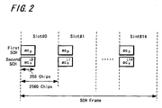
- a transmission timing of the synchronization channel in the W-CDMA method is explained in FIG. 2, in which a first SCH (first synchronization channel) of 256 chips and a second SCH (second synchronization channel) of 256 chips are transmitted at a predetermined interval (head portion) in each slot.
- the present invention addresses the above-identified, and other problems associated with conventional methods and apparatuses and provides a wireless transmission system of this kind in which a channel quality is accurately detected.
- noise components of a desired channel are estimated; degree of a noise component caused by the synchronization channel is estimated with respect to the estimated noise; and a channel quality of a received channel is detected based on the estimated degree of the noise component.
- an accurate channel quality in which degree of the noise component caused by a synchronization channel is taken into consideration can be detected, so that an accurate channel quality can be detected even in a state where a noise component caused by the synchronization channel is influential. Accordingly, by informing the communication destination of the channel quality accurately detected, a desired throughput can be obtained more easily.
- the present invention is applied to the HSDPA (High Speed Downlink Packet Access) method with which high speed downlink data transmission of the UMTS system (Universal Mobile Telecommunications System) that is the wireless telecommunication system to which the W-CDMA method is applied as explained in the description of related art.
- UMTS system Universal Mobile Telecommunications System
- a synchronization channel (refer to FIG. 2) which is not orthogonal to a data channel or the like exists as explained above.
- the HSDPA method is a system applied to a high speed downlink data transmission from a base station of a wireless telephone system to a mobile phone unit.
- a base station of a wireless telephone system to a mobile phone unit.
- an antenna 11 is connected to an RF (high frequency) processor 12, and the RF processor 12 receives a wireless signal of a predetermined frequency band and wirelessly transmits a transmission signal in a predetermined frequency band. Since the W-CDMA method is applied as a wireless connection method, a wireless connection is performed based on the CDMA (Code Division Multiple Access) method.
- the RF processor 12 is connected to a communication processor 13 in which demodulation of a received signal, reception data processing of demodulated data and the like are performed, and transmit data processing, modulation for transmission and the like are also performed.
- the received data and control data obtained in the communication processor 13 are supplied to a controller 14 which is a control unit to control an operation of each unit of this mobile phone unit. Further, the reception data which needs to be stored is stored in a memory 15. Furthermore, received voice data for telephone call is supplied to a circuit of a voice system not shown and is output. Transmission data stored in the memory 15 and the like, is supplied to the communication processor 13 by the control of the controller 14 and transmission processing is performed. A display unit 16 is connected to the controller 14 to perform a display and the like based on the received data. Furthermore, operational information from a key 17 arranged in the mobile phone unit is supplied to the controller 14 and an operation based on a key operation is performed.
- FIG. 4 shows functional blocks to explain a state of the channel quality detection processing, and respective functional blocks shown in FIG. 4 are not necessarily provided in an actual apparatus but may be made into software and are executed by an operation of the controller 14 or the like.
- a received signal of a desired channel (here pilot channel) is sent to a channel noise estimation unit 21. Then, a channel noise of the pilot channel is estimated. A channel noise of a user data channel is estimated from the channel noise of the pilot channel. The estimated channel noise data is sent to a synchronization channel noise ratio estimation unit 22, and the judgment is made by taking degree (ratio) of a noise component caused by the synchronization channel into consideration. The channel quality is judged in a channel quality estimation unit 23 based on the result thereof (synchronization channel noise ratio). Within the channel quality estimation unit 23, a table showing correspondence between a channel quality and a threshold value, which is described later on, is stored in the connected memory or the like.
- the channel quality estimation unit 23 can obtain a final value of the channel quality by referring to data in the table. Further, data made of a plurality of combinations of threshold values (threshold value sets described later on) is stored in the table of this embodiment. The combination of threshold values to be used is selected among those threshold value sets based on the synchronization channel noise ratio.
- a channel state estimated in a channel state estimation unit 24 may be taken into consideration.
- the channel state estimation unit 24 judges the channel quality using a traveling speed of a mobile phone unit, a presence or absence of multipath and the like, for example.
- processing of changing a combination of threshold values to detect the channel quality of the receiving channel, processing of changing a reference time to estimate the noise component, or the like can be performed in the channel quality estimation unit 23.
- a signal noise ratio (SNR) of a downlink pilot channel is obtained, and an SNR of the user data channel is obtained from this SNR of the pilot channel (step S11).
- the noise component caused by the synchronization channel is obtained, and a synchronization channel noise ratio is detected from a ratio of this noise component to the SNR of the user data channel obtained in step S11 (step S12).
- the synchronization channel exists only for an interval of 256 chips in the head portion of each slot.
- the 256-chip interval is equivalent to one symbol of the pilot channel.
- pilot_SNP SCH 10 ⁇ log 10 ( S SCH / N SCH ) [dB]
- pilot symbol pilot channel after demodulation
- S SCH signal power at timing of transmitting synchronization channel
- N SCH noise power at timing of transmitting synchronization channel
- Pilot SNR SCH SNR of pilot channel at timing of transmitting synchronization channel
- N 2 number of pilot channel symbols used to obtain
- j' initial number of pilot channel symbol number used to obtain Pilot SNR SCH are defined.
- the synchronization channel noise ratio is calculated based on the following expression using the SNR (SNR SCH ) of the pilot channel at the timing of transmitting the synchronization channel and the SNR of the pilot channel including the timing other than the timing of transmitting the synchronization channel (step S11).
- SNR SCH Pilot_SNR-Pilot_SNR SCH
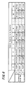
- FIG. 6 is a table showing an example of correspondence between the channel quality and the threshold value according to this embodiment.
- three combinations of set 1, set 2 and set 3 are provided as the threshold value sets, and channel quality values in 31 stages from 0 to 30 are obtained, respectively.
- Each set includes different threshold values to determine the values in those 31 stages.
- threshold values A, B, ..., and I are used when the threshold value set 1 is selected
- threshold values A', B', ..., and I' are used when the threshold value set 2 is selected
- threshold values A", B", ..., and I" are used when the threshold value set 3 is selected.
- step S13 as the processing of selecting a threshold value set based on the synchronization channel noise ratio, the calculated synchronization channel noise ratio is, for example, categorized into three classes of large, medium and small. Then, the threshold value set 1 is used when the synchronization channel noise ratio is categorized as small, the threshold value set 2 is used when the synchronization channel noise ratio is categorized as medium, and the threshold value set 3 is used when the synchronization channel noise ratio is categorized as large.
- the threshold value set presently used is compared with the selected threshold value set, and the threshold value set to be used is changed to the newly selected one when the result of comparison shows difference (step S14).
- the threshold value set to be used remains unchanged when the result of the comparison shows no difference.
- the channel quality values in the 31 stages can be obtained using the threshold values in the threshold value set which is thus set (step S15).
- the data on the channel quality value obtained in this manner is transmitted to the base station.
- the accurate channel quality in which the influence of the synchronization channel is taken into consideration can be detected.
- a pilot channel symbol used to calculate the Pilot SNR (SNR of pilot channel) and a pilot channel symbol used to calculate the Pilot SNR SCH (SNR of pilot channel at timing of transmitting synchronization channel) are different from each other, however, the same calculation method is used. Accordingly, since the White Gaussian Noise becomes influential as the noise component in the case of no large fluctuation in the channel condition of the calculation interval, the Pilot SNR (SNR of pilot channel) and the Pilot SNR SCH come close to correspond with each other and the value of the synchronization channel noise ratio becomes small.
- the ratio of the White Gaussian Noise noise to the synchronization channel noise ratio can be calculated from the synchronization channel noise ratio.
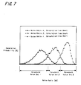
- FIGS. 7 and 8 show the results of simulating generation probability of synchronization channel noise ratio when the noise ratio is fixed to ⁇ , ⁇ , and ⁇ , respectively.
- ⁇ is the highest (the ratio of noise caused by the synchronization channel is small)
- the ratio of the White Gaussian Noise of ⁇ is the lowest (the ratio of noise caused by the synchronization channel is large).
- the calculation interval to obtain the synchronization channel noise ratio is shorter in the results shown in FIG. 7 as compared with the results shown in FIG. 8.
- each value of N1 and N2 in the expressions described above is small. Accordingly, less dispersion is observed in the synchronization channel noise ratio in the results of FIG. 8 and a threshold value set can be set more accurately.
- distribution of the synchronization channel noise ratio varies depending on the noise ratio, and the noise ratio is estimated based on the synchronization channel noise ratio.
- the above-described classification of synchronization channel noise ratio into large, medium and small is made with a value of the Noise Ratio indicating a point where respective distributions intersect in each of FIG. 7 and FIG. 8 as a boundary point, for example. Examples in which the threshold value sets are selected in this manner are described in FIGS. 7 and 8.
- Specific noise ratio corresponds to each of the above-described synchronization channel noise ratios of large, medium and small.
- the threshold value set corresponding to the classification values obtained in an environment of the corresponding noise ratio is used. Specifically, when the noise ratio ⁇ , the noise ratio ⁇ and the noise ratio ⁇ respectively correspond to small, medium and large of synchronization channel noise ratios, the threshold value set 1 is obtained in the condition where the noise ratio is ⁇ .
- the threshold value set 2 is obtained in the condition where the noise ratio is ⁇ .
- the threshold value set 3 is obtained in the condition where the noise ratio is ⁇ .
- the threshold value set 1 is used as a threshold value set in an initial state, for example. Alternatively, a threshold value set used last time may be used in an initial state.
- calculation intervals in FIGS. 7 and 8 may be changed, for example, based on the estimation result in the channel state estimation unit 24 shown in FIG. 4.
- the estimation detection
- the channel state changes frequently, it is difficult to make the calculation time longer.
- threshold value sets may be prepared and the threshold value sets are changed more frequently, allowing unavoidable incorrect categorization when classified.
- another noise ratio may be classified between ⁇ and ⁇ , and between ⁇ and ⁇ , respectively, in FIG. 8 to minutely set five threshold value sets.
- calculated statistics may be used instead of changing the above-described N 1 and N 2 to reduce the dispersion of estimation.
- the statistics of the Pilot SNR and the Pilot SNR SCH can be taken.
- each slot used when obtaining the noise ratio is not limited to that of the above-described embodiment.
- the SNR obtained using the second through tenth symbols of each slot may also be used.
- the symbol used when calculating the Data SNR that is the SNR of the user data channel is not limited either. Although all the symbols are used in the above-described embodiment, only the second through the tenth symbols of each slot may be used.
- the Pilot SNR SCH may be obtained with the pilot symbols influenced by the synchronization channel being first two symbols of each slot.
- symbols to be used may be changed between the case of multi-path and the case of single-path.
- the above-described embodiment is an example of the case where high speed data transmission is performed from a base station to a terminal by applying the present invention to the transmission of the HSDPA method in the UMTS system that is the wireless telecommunication system to which the W-CDMA method is applied, however, needless to say the present invention can be applied to wireless data transmission of other methods.
- This invention can be applied to wireless data communication of various methods other than the wireless telecommunication as long as a method is basically a CDMA method having a synchronization channel.
Abstract
Description


pilot symbol: pilot channel after demodulation
S: signal power
N: noise power
Pilot SNR: SNR of pilot channel
N 1 : number of pilot channel symbols used to obtain SNR of pilot channel
i: symbol number of pilot channel
j: initial number of pilot channel symbol number used for obtaining SNR are defined, respectively.


pilot symbol: pilot channel after demodulation
S SCH : signal power at timing of transmitting synchronization channel
N SCH : noise power at timing of transmitting synchronization channel
Pilot SNR SCH : SNR of pilot channel at timing of transmitting synchronization channel
N 2 : number of pilot channel symbols used to obtain SNR SCH
i' : each symbol number of pilot channel assumed i = 10 × i', where each i=0 indicates pilot channel symbol number at the head portion of slot (with respect to i, refer to explanation of expression of [Formula 3])
j' : initial number of pilot channel symbol number used to obtain Pilot SNR SCH are defined.
Claims (12)
- A channel quality estimation method for estimating a channel quality of a signal transmitted by a Code Division Multiple Access method and for estimating the channel quality in a system having a synchronization channel not orthogonal to a channel which receives data, comprising the steps of:estimating a noise component of a desired channel;estimating degree of a noise component caused by the synchronization channel with respect to said estimated noise; anddetecting the channel quality of a receiving channel based on said estimated degree of the noise component.
- A channel quality estimation method according to claim 1,
wherein a channel quality table for obtaining the channel quality is provided, and
the channel quality of the receiving channel is detected from said estimated degree of the noise component by referring to said channel quality table. - A channel quality estimation method according to claim 1 or 2,
wherein said degree of the noise component is estimated by calculating a signal to noise ratio of said synchronization channel. - A channel quality estimation method according to claim 1 or 2,
wherein said of degree of the noise component is estimated by judging a channel state of said receiving channel. - A channel quality estimation method according to claim 4,
wherein a combination of threshold values for detecting said channel quality of the receiving channel is changed in accordance with said judgment of the channel state. - A channel quality estimation method according to one of the claims 1 to 5,
wherein a reference time for estimating said noise component of the desired channel is changed in accordance with said judgment of the channel state. - A receiving apparatus to receive a signal transmitted by a Code Division Multiple Access method and to estimate a channel quality in a system having a synchronization channel not orthogonal to a channel which receives data, comprising:noise component estimation means (21) to estimate a noise component of a desired channel;synchronization channel noise degree estimation means (22) to estimate degree of a noise component caused by the synchronization channel with respect to the noise estimated by said noise component estimation means (21); andchannel quality detection means (23) to detect the channel quality of a receiving channel based on the degree of the noise component estimated in said synchronization channel noise degree estimation means (22).
- A receiving apparatus according to claim 7,
wherein said channel quality detection means (23) includes a channel quality table for obtaining the channel quality, and
the channel quality of the receiving channel is detected from degree of the noise component estimated by said synchronization channel noise degree estimation means (22) by referring to said channel quality table. - A receiving apparatus according to claim 7 or 8,
wherein degree of the noise component is estimated in said synchronization channel noise degree estimation means (22) by calculating a signal to noise ratio of said synchronization channel. - A receiving apparatus according to claim 7 or 8,
wherein degree of the noise component is estimated in said synchronization channel noise degree estimation means (22) by judging a channel state of the receiving channel. - A receiving apparatus according to claim 10,
wherein a combination of threshold values for detecting the channel quality of the receiving channel is changed in accordance with said judgment of the channel state. - A receiving apparatus according to claim 10 or 11,
wherein a reference time for estimating the noise component is changed in said noise component estimation means in accordance with said judgment of the channel state.
Applications Claiming Priority (2)
| Application Number | Priority Date | Filing Date | Title |
|---|---|---|---|
| JP2004130070 | 2004-04-26 | ||
| JP2004130070A JP4387239B2 (en) | 2004-04-26 | 2004-04-26 | Reception quality judgment method and receiving apparatus |
Publications (1)
| Publication Number | Publication Date |
|---|---|
| EP1592143A1 true EP1592143A1 (en) | 2005-11-02 |
Family
ID=34935734
Family Applications (1)
| Application Number | Title | Priority Date | Filing Date |
|---|---|---|---|
| EP05009090A Withdrawn EP1592143A1 (en) | 2004-04-26 | 2005-04-26 | Channel quality estimation method and receiving apparatus cross references to related applications |
Country Status (5)
| Country | Link |
|---|---|
| US (1) | US7606294B2 (en) |
| EP (1) | EP1592143A1 (en) |
| JP (1) | JP4387239B2 (en) |
| KR (1) | KR101051676B1 (en) |
| CN (1) | CN100452691C (en) |
Cited By (1)
| Publication number | Priority date | Publication date | Assignee | Title |
|---|---|---|---|---|
| US7979075B2 (en) | 2006-05-03 | 2011-07-12 | Telefonaktiebolaget Lm Ericsson (Publ) | Generation, deployment and use of tailored channel quality indicator tables |
Families Citing this family (8)
| Publication number | Priority date | Publication date | Assignee | Title |
|---|---|---|---|---|
| US8009777B2 (en) * | 2007-06-15 | 2011-08-30 | Icera, Inc. | Processing data in a digital communications system |
| US8050237B2 (en) * | 2007-08-01 | 2011-11-01 | Broadcom Corporation | Synchronization channel noise power estimation |
| US20090291643A1 (en) * | 2008-05-22 | 2009-11-26 | Ralink Technology Corporation | Method and system for measuring noise signal |
| WO2010025568A1 (en) * | 2008-09-05 | 2010-03-11 | Icera Canada ULC | A method and system for dynamic signal to noise ratio adjustment in a transceiver |
| US8238482B2 (en) | 2008-10-14 | 2012-08-07 | Apple Inc. | Techniques for improving channel estimation and tracking in a wireless communication system |
| US8170599B2 (en) * | 2008-11-21 | 2012-05-01 | Telefonaktiebolaget Lm Ericsson (Publ) | Format based power control |
| US8804876B2 (en) * | 2009-02-20 | 2014-08-12 | Qualcomm Incorporated | Enhanced modulation detection |
| US9614700B2 (en) * | 2013-01-02 | 2017-04-04 | Qualcomm Incorporated | Techniques for channel estimation in millimeter-wave communication systems |
Citations (2)
| Publication number | Priority date | Publication date | Assignee | Title |
|---|---|---|---|---|
| US5771461A (en) * | 1996-06-28 | 1998-06-23 | Motorola, Inc. | Method and apparatus for power control of a first channel based on a signal quality of a second channel |
| EP1221777A1 (en) * | 2000-12-20 | 2002-07-10 | TELEFONAKTIEBOLAGET LM ERICSSON (publ) | Method and apparatus for classifying interference |
Family Cites Families (7)
| Publication number | Priority date | Publication date | Assignee | Title |
|---|---|---|---|---|
| US5144642A (en) * | 1990-06-07 | 1992-09-01 | Stanford Telecommunications, Inc | Interference detection and characterization method and apparatus |
| US6131013A (en) * | 1998-01-30 | 2000-10-10 | Motorola, Inc. | Method and apparatus for performing targeted interference suppression |
| RU2195784C2 (en) * | 1998-06-13 | 2002-12-27 | Самсунг Электроникс Ко., Лтд. | Device and method measuring power of nonorthogonal noise in communication system with code-division multiple access |
| WO2002051044A1 (en) * | 2000-12-20 | 2002-06-27 | Telefonaktiebolaget Lm Ericsson (Publ) | Method and apparatus for classifying interference |
| US7292552B2 (en) * | 2002-03-14 | 2007-11-06 | Qualcomm Incorporated | Method and apparatus for reducing interference in a wireless communication system |
| US7751843B2 (en) * | 2002-07-29 | 2010-07-06 | Qualcomm Incorporated | Reducing interference with a multiple format channel in a communication system |
| US7386030B2 (en) * | 2004-02-17 | 2008-06-10 | Texas Instruments Incorporated | Automatic threshold selection method for improving the detection of a wireless signal |
-
2004
- 2004-04-26 JP JP2004130070A patent/JP4387239B2/en not_active Expired - Fee Related
-
2005
- 2005-04-21 US US11/110,932 patent/US7606294B2/en not_active Expired - Fee Related
- 2005-04-25 KR KR20050034073A patent/KR101051676B1/en not_active IP Right Cessation
- 2005-04-26 CN CNB2005100668076A patent/CN100452691C/en not_active Expired - Fee Related
- 2005-04-26 EP EP05009090A patent/EP1592143A1/en not_active Withdrawn
Patent Citations (2)
| Publication number | Priority date | Publication date | Assignee | Title |
|---|---|---|---|---|
| US5771461A (en) * | 1996-06-28 | 1998-06-23 | Motorola, Inc. | Method and apparatus for power control of a first channel based on a signal quality of a second channel |
| EP1221777A1 (en) * | 2000-12-20 | 2002-07-10 | TELEFONAKTIEBOLAGET LM ERICSSON (publ) | Method and apparatus for classifying interference |
Non-Patent Citations (1)
| Title |
|---|
| "HSDPA CQI Proposal", TSG-RAN WG1 HSDPA, XX, XX, 9 April 2002 (2002-04-09), pages 1 - 6, XP002330513 * |
Cited By (1)
| Publication number | Priority date | Publication date | Assignee | Title |
|---|---|---|---|---|
| US7979075B2 (en) | 2006-05-03 | 2011-07-12 | Telefonaktiebolaget Lm Ericsson (Publ) | Generation, deployment and use of tailored channel quality indicator tables |
Also Published As
| Publication number | Publication date |
|---|---|
| CN1691564A (en) | 2005-11-02 |
| US20050238086A1 (en) | 2005-10-27 |
| KR20060045845A (en) | 2006-05-17 |
| JP2005311980A (en) | 2005-11-04 |
| JP4387239B2 (en) | 2009-12-16 |
| US7606294B2 (en) | 2009-10-20 |
| CN100452691C (en) | 2009-01-14 |
| KR101051676B1 (en) | 2011-07-26 |
Similar Documents
| Publication | Publication Date | Title |
|---|---|---|
| EP1592143A1 (en) | Channel quality estimation method and receiving apparatus cross references to related applications | |
| US8165106B2 (en) | Apparatus and method for detecting a ranging signal in a wireless communication system | |
| US9369914B1 (en) | Adaptively determining a data rate of packetized information transmission over a wireless channel | |
| US20030012308A1 (en) | Adaptive channel estimation for wireless systems | |
| JP2014161073A (en) | Time shifting of co-channel data transmissions to reduce co-channel interference | |
| US9730094B2 (en) | Bursty-interference-aware interference management | |
| WO2008069624A1 (en) | Structure and construction method of uplink control channel in mobile wideband wireless access system | |
| EP1985030B1 (en) | Guidance device and guidance method | |
| JP2012508523A (en) | Bluetooth spectral sensing using multiple energy detection measurement sequences | |
| JP5368457B2 (en) | Communication device and method | |
| US8891591B2 (en) | Receiver circuit and method | |
| US20040127245A1 (en) | System and method for intelligent transmitted power control scheme | |
| KR20020015692A (en) | Radio communication apparatus and radio communication method | |
| US20090080555A1 (en) | Guard interval lenght selection in an ofdm systems based on coherence bandwidth of the channel | |
| US20060153144A1 (en) | Pilot-based channel estimation method for MC-CDMA system | |
| WO2005041602A1 (en) | Mobile terminal position measurement system | |
| US20090067524A1 (en) | Guard interval lenght selection in an ofdm systems based on coherence bandwidth of the channel | |
| US7529555B2 (en) | Transmission rate determination method, and base station apparatus, terminal apparatus, and communication system using the same | |
| US20040203423A1 (en) | Base station | |
| US8311080B2 (en) | Mobile communication terminal, synchronization judging circuit used in the mobile communication terminal, control method, synchronization judging control program | |
| KR20110069337A (en) | Apparatus and method for transmitting/receiving data in wireless communication system | |
| CN111614374B (en) | Multi-slot PUCCH frequency hopping method and frequency hopping selection device | |
| EP1956784A1 (en) | Mobile terminal and method for measuring channel quality | |
| JP2001308733A (en) | Radio receiver and radio receiving method |
Legal Events
| Date | Code | Title | Description |
|---|---|---|---|
| PUAI | Public reference made under article 153(3) epc to a published international application that has entered the european phase |
Free format text: ORIGINAL CODE: 0009012 |
|
| AK | Designated contracting states |
Kind code of ref document: A1 Designated state(s): AT BE BG CH CY CZ DE DK EE ES FI FR GB GR HU IE IS IT LI LT LU MC NL PL PT RO SE SI SK TR |
|
| AX | Request for extension of the european patent |
Extension state: AL BA HR LV MK YU |
|
| 17P | Request for examination filed |
Effective date: 20051124 |
|
| AKX | Designation fees paid |
Designated state(s): DE FR GB |
|
| 17Q | First examination report despatched |
Effective date: 20060814 |
|
| RAP1 | Party data changed (applicant data changed or rights of an application transferred) |
Owner name: SONY MOBILE COMMUNICATIONS JAPAN, INC. |
|
| GRAP | Despatch of communication of intention to grant a patent |
Free format text: ORIGINAL CODE: EPIDOSNIGR1 |
|
| INTG | Intention to grant announced |
Effective date: 20160208 |
|
| RAP1 | Party data changed (applicant data changed or rights of an application transferred) |
Owner name: SONY MOBILE COMMUNICATIONS INC. |
|
| GRAS | Grant fee paid |
Free format text: ORIGINAL CODE: EPIDOSNIGR3 |
|
| GRAP | Despatch of communication of intention to grant a patent |
Free format text: ORIGINAL CODE: EPIDOSNIGR1 |
|
| INTG | Intention to grant announced |
Effective date: 20160719 |
|
| STAA | Information on the status of an ep patent application or granted ep patent |
Free format text: STATUS: GRANT OF PATENT IS INTENDED |
|
| STAA | Information on the status of an ep patent application or granted ep patent |
Free format text: STATUS: THE APPLICATION IS DEEMED TO BE WITHDRAWN |
|
| 18D | Application deemed to be withdrawn |
Effective date: 20161130 |