EP1591660A1 - Peristaltic pumping system - Google Patents
Peristaltic pumping system Download PDFInfo
- Publication number
- EP1591660A1 EP1591660A1 EP04405275A EP04405275A EP1591660A1 EP 1591660 A1 EP1591660 A1 EP 1591660A1 EP 04405275 A EP04405275 A EP 04405275A EP 04405275 A EP04405275 A EP 04405275A EP 1591660 A1 EP1591660 A1 EP 1591660A1
- Authority
- EP
- European Patent Office
- Prior art keywords
- rollers
- pumping system
- peristaltic pumping
- driving
- planar
- Prior art date
- Legal status (The legal status is an assumption and is not a legal conclusion. Google has not performed a legal analysis and makes no representation as to the accuracy of the status listed.)
- Withdrawn
Links
Images

Classifications
-
- F—MECHANICAL ENGINEERING; LIGHTING; HEATING; WEAPONS; BLASTING
- F04—POSITIVE - DISPLACEMENT MACHINES FOR LIQUIDS; PUMPS FOR LIQUIDS OR ELASTIC FLUIDS
- F04B—POSITIVE-DISPLACEMENT MACHINES FOR LIQUIDS; PUMPS
- F04B43/00—Machines, pumps, or pumping installations having flexible working members
- F04B43/12—Machines, pumps, or pumping installations having flexible working members having peristaltic action
- F04B43/1253—Machines, pumps, or pumping installations having flexible working members having peristaltic action by using two or more rollers as squeezing elements, the rollers moving on an arc of a circle during squeezing
Definitions
- the invention relates to peristaltic pumping systems comprising a flexible tube, a series of rollers adapted to compress the flexible tube in a peristaltic way, a driving unit and a housing which comprises a preferable cylindrical raceway for receiving the flexible tube.
- a peristaltic pump unit of this kind is disclosed for instance in US 5 044 902.
- This unit discloses the use of a central shaft which is in direct contact with the rollers.
- the shaft has two functions, namely, driving the rollers during use and pushing them against the flexible tube when the shaft is inserted into the system.
- This unit shows however some disadvantages. For instance, it wears rapidly and frequently blocks due to the opposite rotation direction of adjacent rollers.
- One object of the invention is to provide a peristaltic pumping system of the type defined above, which is of a simple and robust construction and which allows an efficient pumping over prolonged period of time.
- the peristaltic pumping system comprises a flexible tube, a substantially cylindrical rotating roller unit containing a series of rollers which are freely rotating around their axes and freely moving along a radial segment, holding means for commonly holding the rollers, a central spreader element for pushing the rollers against the flexible tube and a driving unit comprising a driving coupling element, characterized by the fact that said holding means is made of at least one planar element having retaining and guiding means along such radial segment for rollers, said planar element being furthermore adapted to be directly coupled to said coupling element in such a way that rollers are driven through said planar element.
- the housing has preferably an internal groove with a concave cross-section into which is housed the flexible tube, while the rollers are externally barrel-shaped, with a convex curvature combined with the concave curvature of the groove of the housing, to rest against the flexible tube; such a housing with a concave internal profile allows a self-centering of the tube and the rollers.
- the tubular rollers are generally made of a flexible plastic material. Their shape is not limited to shape indicated previously. They may be cylindrical or conical. They may also be of a flexible material to improve the elastic functioning of the peristaltic pumping system.
- the driving unit preferably comprises a driving shaft provided with a support containing pins which are adapted to cooperate with holes in the planar element of the roller unit.
- the spreader is loosely mounted on an extension of the driving shaft to avoid any friction with the rollers during use.
- a peristaltic pump system can be seen on figure comprising a housing 9 containing a raceway 10 for receiving a flexible tube (not shown), forming the body of the pump.
- the tube is interposed between the housing walls and a roller unit 8,11 capable of co-operating with a support 2 fixed to a driving shaft 1 which is, in turn, driven by an electric motor (not shown).
- Figure 3 and 5 represents a non-active position where the driving shaft 1 has not penetrated the roller unit 8,11.
- the roller unit 8,11 is made of three rollers 11 held between two separator discs 8 , the rollers 11 are commonly retained and guided through their axis ends 12 to separator discs 8.
- At least one separator disc 8 contains a plurality of receiving means 13 which are adapted to receive the pins 3 of the driving support 2.
- the driving shaft distal end extends from the driving support 2 and is covered by a sheath 5 freely rotating around the driving shaft 1.
- the sheath 5 is sufficiently large in order to act as a spreader which pushes the rollers 11 against the flexible tube when the shaft distal end penetrates the roller unit 8,11 (see figures 4 and 6).
- the tube can be kept in position by two welded stop rings foreseen for being clamped into accurate recesses under the pressure of a supporting collar integral with the cover of the cartridge.
- this tube When manufactured in series, this tube is mounted very quickly into the cartridge.
- the peristaltic pump unit operates as follows : The housing 9 and the roller unit 8,11 are first placed on the driving unit 1,2 (see fig. 4 and 6) . By this movement, the central shaft distal end, together with the sheath 5, pushes the rollers 11 against the tube and, in addition, the pins 3 engage the receiving means 13 of the discs 8.
- the coupling of said pin 3 in the receiving means can be self-aligned by having receiving means which are close to each other with a taper at the periphery to guide the pin into said receiving, said pin having a conical end.
- the coupling can also be obtained by pins being placed on the disc 8 and the receiving means being placed on the driving unit 2.
- the pumping action is obtained when the motor is started to rotate, driving the discs 8 and the rollers 11.
- the driving of the disc 8 can also be obtained by a gear coupling on the periphery of such planar disc.
- the rollers are not able to return to the center position once they have been pushed by the central shaft and sheath 5 against the flexible tube.
- the peristaltic system remains occlusive, such as to prevent free-flow after use. This can, for example, be obtained by having a cliquing position 14 on the separator discs at the position of the roller axis ends on the radial segment 15 of the separator discs so that the roller axis end has to pass such click 14 when the central shaft is inserted, but cannot return afterwards when the central shaft is removed.
- this can also be obtained by having the sheath 5 remaining inside the roller unit 8,9 after the shaft is removed.
Abstract
Peristaltic pumping system comprising a flexible tube, a substantially cylindrical
rotating roller unit (8,11) containing a series of rollers (11) which are freely rotating
around their axes and freely moving along a radial segment, holding means (8) for
commonly holding the rollers (11), a central spreader element (5) for pushing the
rollers (11) against the flexible tube and a driving unit (1,2) comprising a driving
coupling element (1), characterized by the fact that said holding means (8) is
made of at least one planar element (8) having retaining and guiding means for
rollers (11), said planar element (8) being furthermore adapted to be directly
coupled to said coupling element (1,2) in such a way that rollers (11) are driven
through said planar element (8).
Description
- The invention relates to peristaltic pumping systems comprising a flexible tube, a series of rollers adapted to compress the flexible tube in a peristaltic way, a driving unit and a housing which comprises a preferable cylindrical raceway for receiving the flexible tube.
- A peristaltic pump unit of this kind is disclosed for instance in US 5 044 902. This unit discloses the use of a central shaft which is in direct contact with the rollers. The shaft has two functions, namely, driving the rollers during use and pushing them against the flexible tube when the shaft is inserted into the system. This unit shows however some disadvantages. For instance, it wears rapidly and frequently blocks due to the opposite rotation direction of adjacent rollers.
- One object of the invention is to provide a peristaltic pumping system of the type defined above, which is of a simple and robust construction and which allows an efficient pumping over prolonged period of time.
- The peristaltic pumping system according to the invention comprises a flexible tube, a substantially cylindrical rotating roller unit containing a series of rollers which are freely rotating around their axes and freely moving along a radial segment, holding means for commonly holding the rollers, a central spreader element for pushing the rollers against the flexible tube and a driving unit comprising a driving coupling element, characterized by the fact that said holding means is made of at least one planar element having retaining and guiding means along such radial segment for rollers, said planar element being furthermore adapted to be directly coupled to said coupling element in such a way that rollers are driven through said planar element.
When the roller unit and the housing are separated from the driving unit, the rollers are brought back to the center under the pressure of the tube at rest, this tube remaining open, which makes possible an easy and complete sterilization. - The housing has preferably an internal groove with a concave cross-section into which is housed the flexible tube, while the rollers are externally barrel-shaped, with a convex curvature combined with the concave curvature of the groove of the housing, to rest against the flexible tube; such a housing with a concave internal profile allows a self-centering of the tube and the rollers.
- The tubular rollers are generally made of a flexible plastic material. Their shape is not limited to shape indicated previously. They may be cylindrical or conical. They may also be of a flexible material to improve the elastic functioning of the peristaltic pumping system.
- The driving unit preferably comprises a driving shaft provided with a support containing pins which are adapted to cooperate with holes in the planar element of the roller unit.
- Preferably the spreader is loosely mounted on an extension of the driving shaft to avoid any friction with the rollers during use.
- The invention consists, besides the arrangements explained above, in a number of other arrangements which will be more explicitly explained below with respect to the particular embodiments described with reference to the attached drawings, but which are in no way restrictive.
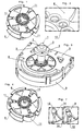
- FIG. 1 of these drawings is a perspective view of a roller unit according to the invention.
- FIG. 2 is an enlarged view of a portion of the roller unit of fig. 1.
- FIG. 3 shows a peristaltic pump unit according to the invention including the roller unit, the housing, the driving shaft and the spreader.
- FIG. 4 represents the roller unit of fig. 1 containing the spreader.
- FIG. 5 is a longitudinal cross-section of the roller unit with the spreader-shaft arrangement in a non-active position.
- FIG. 6 is a longitudinal cross-section of the roller unit with the spreader-shaft arrangement in an active position.
- FIG. 7 is en enlarged view of a disc portion.
-
- With reference to the drawings, a peristaltic pump system can be seen on figure comprising a
housing 9 containing araceway 10 for receiving a flexible tube (not shown), forming the body of the pump. The tube is interposed between the housing walls and aroller unit support 2 fixed to a driving shaft 1 which is, in turn, driven by an electric motor (not shown). - Figure 3 and 5 represents a non-active position where the driving shaft 1 has not penetrated the
roller unit - The
roller unit rollers 11 held between twoseparator discs 8, therollers 11 are commonly retained and guided through theiraxis ends 12 toseparator discs 8. At least oneseparator disc 8 contains a plurality of receivingmeans 13 which are adapted to receive thepins 3 of thedriving support 2. - The driving shaft distal end extends from the
driving support 2 and is covered by asheath 5 freely rotating around the driving shaft 1. Thesheath 5 is sufficiently large in order to act as a spreader which pushes therollers 11 against the flexible tube when the shaft distal end penetrates theroller unit 8,11 (see figures 4 and 6). - When the
housing 9 and theroller unit driving unit 1,2 , therollers 11 are brought back to the center under the pressure of the tube at rest, as can be seen in Figure 1, this tube remaining open until stabilization of the rollers in a perpendicular position of reciprocal support. This allows to avoid a plastic deformation of the walls of the tube during storage, which could occur if the tube were stored in compressed condition and thereby induce a change in peristaltic performance during use (in particular with regard to flow rate and accuracy). - The tube can be kept in position by two welded stop rings foreseen for being clamped into accurate recesses under the pressure of a supporting collar integral with the cover of the cartridge.
- When manufactured in series, this tube is mounted very quickly into the cartridge.
- The peristaltic pump unit operates as follows :
Thehousing 9 and theroller unit sheath 5, pushes therollers 11 against the tube and, in addition, thepins 3 engage thereceiving means 13 of thediscs 8. The coupling of saidpin 3 in the receiving means can be self-aligned by having receiving means which are close to each other with a taper at the periphery to guide the pin into said receiving, said pin having a conical end. - Alternatively, the coupling can also be obtained by pins being placed on the
disc 8 and the receiving means being placed on thedriving unit 2. - The pumping action is obtained when the motor is started to rotate, driving the
discs 8 and therollers 11. - Alternatively, the driving of the
disc 8 can also be obtained by a gear coupling on the periphery of such planar disc. - When the
roller unit housing 9 are separated from thedriving unit 1,2 therollers 11 are brought back to the centre under the pressure of the tube at rest, this tube remaining open. - In an alternative embodiment (not shown) the rollers are not able to return to the center position once they have been pushed by the central shaft and
sheath 5 against the flexible tube. In such a case, once the central shaft has been removed the peristaltic system remains occlusive, such as to prevent free-flow after use. This can, for example, be obtained by having acliquing position 14 on the separator discs at the position of the roller axis ends on theradial segment 15 of the separator discs so that the roller axis end has to passsuch click 14 when the central shaft is inserted, but cannot return afterwards when the central shaft is removed. - Alternatively, this can also be obtained by having the
sheath 5 remaining inside theroller unit
Claims (9)
- Peristaltic pumping system comprising a flexible tube, a substantially cylindrical rotating roller unit (8,11) containing a series of rollers (11) which are freely rotating around their axes and freely moving along a radial segment (15), holding means (8) for commonly holding the rollers (11), a central spreader element (5) for pushing the rollers (11) against the flexible tube and a driving unit (1,2) comprising a driving coupling element (1), characterized by the fact that said holding means (8) is made of at least one planar element (8) having retaining and guiding means for rollers (11), said planar element (8) being furthermore adapted to be directly coupled to said coupling element (1,2) in such a way that rollers (11) are driven through said planar element (8).
- Peristaltic pumping system according to claim 1 wherein said holding means is made of two parallel planar elements (8), the rollers (11) being situated between said planar elements (8).
- Peristaltic pumping system according to claim 1 or 2 wherein said spreader element (5) is freely mounted on the distal end of the driving shaft (1).
- Peristaltic pumping system according to claim 1, 2 or 3 wherein said driving coupling element is directly fixed around the basis of the central spreader element to be coupled to the planar element by underneath.
- Peristaltic pumping system according to claim 4, wherein the driving coupling element comprises centering means adapted to allow a self centering of the driving coupling element.
- Peristaltic pumping system according to claim 1, 2, 3, 4 or 5 wherein said planar element(s) (8) contain(s) a series of holes (13) situated along a circle which is coaxial with respect to the rotating axis of the roller unit (8,11) and wherein said driving unit (1,2) contains at least one pin (3) adapted to be received in one of said holes (13), the pin (3)-hole(13) combination allowing the fixation of the planar element (8) to the driving unit (1,2).
- Peristaltic pumping system according to claim 6 wherein said holes (13) are adjacent along the circle, allowing thereby always a fixation (automatic alignment) of the planar element (8) to the driving unit (1,2) when both elements are approached.
- Peristaltic pumping system according to claim 1, 2 or 3 wherein said driving coupling element (1,2) is directly fixed around the periphery of the planar element (8).
- Peristaltic pumping system according to any of the previous claims comprising clicking means (14) adapted to maintain the rollers against the flexible tube when the central shaft is withdrawn.
Priority Applications (7)
| Application Number | Priority Date | Filing Date | Title |
|---|---|---|---|
| EP04405275A EP1591660A1 (en) | 2004-04-30 | 2004-04-30 | Peristaltic pumping system |
| US11/587,438 US8297956B2 (en) | 2004-04-30 | 2005-04-27 | Peristaltic pumping system |
| AT05731140T ATE394597T1 (en) | 2004-04-30 | 2005-04-27 | HOSE PUMP SYSTEM |
| DE602005006552T DE602005006552D1 (en) | 2004-04-30 | 2005-04-27 | HOSE PUMP SYSTEM |
| EP05731140A EP1743100B1 (en) | 2004-04-30 | 2005-04-27 | Peristaltic pumping system |
| PCT/IB2005/051372 WO2005106251A1 (en) | 2004-04-30 | 2005-04-27 | Peristaltic pumping system |
| JP2007510222A JP4838237B2 (en) | 2004-04-30 | 2005-04-27 | Peristaltic pump system |
Applications Claiming Priority (1)
| Application Number | Priority Date | Filing Date | Title |
|---|---|---|---|
| EP04405275A EP1591660A1 (en) | 2004-04-30 | 2004-04-30 | Peristaltic pumping system |
Publications (1)
| Publication Number | Publication Date |
|---|---|
| EP1591660A1 true EP1591660A1 (en) | 2005-11-02 |
Family
ID=34932087
Family Applications (2)
| Application Number | Title | Priority Date | Filing Date |
|---|---|---|---|
| EP04405275A Withdrawn EP1591660A1 (en) | 2004-04-30 | 2004-04-30 | Peristaltic pumping system |
| EP05731140A Not-in-force EP1743100B1 (en) | 2004-04-30 | 2005-04-27 | Peristaltic pumping system |
Family Applications After (1)
| Application Number | Title | Priority Date | Filing Date |
|---|---|---|---|
| EP05731140A Not-in-force EP1743100B1 (en) | 2004-04-30 | 2005-04-27 | Peristaltic pumping system |
Country Status (6)
| Country | Link |
|---|---|
| US (1) | US8297956B2 (en) |
| EP (2) | EP1591660A1 (en) |
| JP (1) | JP4838237B2 (en) |
| AT (1) | ATE394597T1 (en) |
| DE (1) | DE602005006552D1 (en) |
| WO (1) | WO2005106251A1 (en) |
Families Citing this family (7)
| Publication number | Priority date | Publication date | Assignee | Title |
|---|---|---|---|---|
| CN102155399A (en) * | 2011-03-18 | 2011-08-17 | 无锡市华茂电器研究所 | Pipe jacket for peristaltic pump |
| EP2503150A1 (en) | 2011-03-21 | 2012-09-26 | SMC-Swiss Medical Care S.A. | Device for detecting and measuring the rotation of a peristaltic cassette |
| WO2013043889A1 (en) | 2011-09-21 | 2013-03-28 | Medrad, Inc. | System and assembly method for a fluid pump device for a continuous multi-fluid delivery system |
| AU2016205275B2 (en) | 2015-01-09 | 2020-11-12 | Bayer Healthcare Llc | Multiple fluid delivery system with multi-use disposable set and features thereof |
| WO2017112916A1 (en) | 2015-12-24 | 2017-06-29 | Hologic, Inc. | Uterine distension fluid management system with peristaltic pumps |
| WO2018172217A1 (en) | 2017-03-23 | 2018-09-27 | Medela Holding Ag | Device with a peristaltic pump unit which can be coupled |
| EP4309698A1 (en) | 2022-07-22 | 2024-01-24 | Medela Holding AG | Peristaltic pump with planetary gear |
Citations (4)
| Publication number | Priority date | Publication date | Assignee | Title |
|---|---|---|---|---|
| US4573887A (en) * | 1983-09-16 | 1986-03-04 | S. E. Rykoff & Co. | Corrosion-resistant roller-type pump |
| US4909713A (en) * | 1986-05-07 | 1990-03-20 | Cobe Laboratories, Inc. | Peristaltic pump |
| US5044902A (en) * | 1989-03-13 | 1991-09-03 | Edouard Malbec | Cartridge for peristaltic pump with a flexible tube, and peristaltic pump fitted with such a cartridge |
| US5927956A (en) * | 1998-09-01 | 1999-07-27 | Linvatec Corporation | Peristaltic pump tubing system with latching cassette |
Family Cites Families (6)
| Publication number | Priority date | Publication date | Assignee | Title |
|---|---|---|---|---|
| US3447478A (en) * | 1967-03-03 | 1969-06-03 | Miles Lab | Peristaltic pump |
| JPS5961943A (en) * | 1982-10-01 | 1984-04-09 | Toshiba Corp | Wafer transfer mechanism |
| WO1994005345A1 (en) * | 1992-09-02 | 1994-03-17 | Valery Viktorovich Skobelev | Pump for biological liquids |
| JPH07122434A (en) | 1993-10-21 | 1995-05-12 | Matsushita Electric Ind Co Ltd | Inductance component and composite component |
| JP2002086761A (en) * | 2000-09-12 | 2002-03-26 | Seiko Epson Corp | Tube pump and ink-jet recording apparatus using the same |
| US7591639B2 (en) * | 2004-04-27 | 2009-09-22 | Hewlett-Packard Development Company, L.P. | Peristaltic pump |
-
2004
- 2004-04-30 EP EP04405275A patent/EP1591660A1/en not_active Withdrawn
-
2005
- 2005-04-27 DE DE602005006552T patent/DE602005006552D1/en active Active
- 2005-04-27 JP JP2007510222A patent/JP4838237B2/en not_active Expired - Fee Related
- 2005-04-27 EP EP05731140A patent/EP1743100B1/en not_active Not-in-force
- 2005-04-27 WO PCT/IB2005/051372 patent/WO2005106251A1/en active IP Right Grant
- 2005-04-27 AT AT05731140T patent/ATE394597T1/en not_active IP Right Cessation
- 2005-04-27 US US11/587,438 patent/US8297956B2/en not_active Expired - Fee Related
Patent Citations (4)
| Publication number | Priority date | Publication date | Assignee | Title |
|---|---|---|---|---|
| US4573887A (en) * | 1983-09-16 | 1986-03-04 | S. E. Rykoff & Co. | Corrosion-resistant roller-type pump |
| US4909713A (en) * | 1986-05-07 | 1990-03-20 | Cobe Laboratories, Inc. | Peristaltic pump |
| US5044902A (en) * | 1989-03-13 | 1991-09-03 | Edouard Malbec | Cartridge for peristaltic pump with a flexible tube, and peristaltic pump fitted with such a cartridge |
| US5927956A (en) * | 1998-09-01 | 1999-07-27 | Linvatec Corporation | Peristaltic pump tubing system with latching cassette |
Also Published As
| Publication number | Publication date |
|---|---|
| WO2005106251A1 (en) | 2005-11-10 |
| DE602005006552D1 (en) | 2008-06-19 |
| JP2007535637A (en) | 2007-12-06 |
| JP4838237B2 (en) | 2011-12-14 |
| EP1743100A1 (en) | 2007-01-17 |
| ATE394597T1 (en) | 2008-05-15 |
| EP1743100B1 (en) | 2008-05-07 |
| US8297956B2 (en) | 2012-10-30 |
| US20080014105A1 (en) | 2008-01-17 |
Similar Documents
| Publication | Publication Date | Title |
|---|---|---|
| EP1743100B1 (en) | Peristaltic pumping system | |
| EP1825144B1 (en) | Peristaltic pump | |
| US7762795B2 (en) | Rotary axial peristaltic pumps and related methods | |
| US5741125A (en) | Peristaltic pump device having an insert cassette of reduced complexity | |
| US4472116A (en) | Infusion pumping apparatus | |
| US5655897A (en) | Peristaltic pump cassette | |
| RU2676585C2 (en) | Hose pump | |
| US7980835B2 (en) | Tube retainer system for a peristaltic pump | |
| EP1457677A3 (en) | Self-loading peristaltic pump for extracorporeal blood circuit | |
| EP2755700B1 (en) | Peristaltic pump with multiple independent channels | |
| ES2421086T3 (en) | Uniform flow volumetric pump | |
| KR20170093219A (en) | Peristaltic pumps | |
| US20170184088A1 (en) | Uterine distension fluid management system with peristaltic pumps | |
| US20090275959A1 (en) | Multiple clip device and multiple clip application apparatus | |
| US4472117A (en) | Infusion pumping apparatus | |
| WO2011059040A1 (en) | Tube pump and tube stabilizer | |
| US7074021B2 (en) | Cartridge to be used with a peristaltic pump | |
| JP5584774B2 (en) | Peristaltic pump and hose cartridge therefor | |
| JP5538829B2 (en) | Tube pump | |
| EP3483441B1 (en) | Peristaltic tube pump | |
| JPS6120737B2 (en) | ||
| CN110268159A (en) | Peristaltic pump and method for realizing peristaltic pump | |
| CZ12188U1 (en) | Peristaltic rotary pump with precise proportioning |
Legal Events
| Date | Code | Title | Description |
|---|---|---|---|
| PUAI | Public reference made under article 153(3) epc to a published international application that has entered the european phase |
Free format text: ORIGINAL CODE: 0009012 |
|
| AK | Designated contracting states |
Kind code of ref document: A1 Designated state(s): AT BE BG CH CY CZ DE DK EE ES FI FR GB GR HU IE IT LI LU MC NL PL PT RO SE SI SK TR |
|
| AX | Request for extension of the european patent |
Extension state: AL HR LT LV MK |
|
| AKX | Designation fees paid | ||
| REG | Reference to a national code |
Ref country code: DE Ref legal event code: 8566 |
|
| STAA | Information on the status of an ep patent application or granted ep patent |
Free format text: STATUS: THE APPLICATION IS DEEMED TO BE WITHDRAWN |
|
| 18D | Application deemed to be withdrawn |
Effective date: 20060503 |