FIELD
-
This invention relates to medical devices for sensing and measuring
biological activity. More particularly, this invention relates to portable bio-sensors,
including self-contained bio-sensors, capable of sensing and
measuring cardiopulmonary activity.
BACKGROUND
-
A large number of chronic diseases are related to the dysfunction of the
cardiopulmonary system. Modern lifestyles and environments predispose
individuals to chronic obstructive pulmonary disorders (such as asthma and
chronic obstructive pulmonary disease) and ischemic heart disease. Moreover,
the cardiopulmonary system is functionally interconnected in many respects,
such that alterations in heart function are sometimes associated with changes in
the lungs.
-
The prevalence of heart and lung disorders has led to the development of
many devices for detecting and monitoring dysfunction in these organ systems.
An example of such a device is the spirometer, which is an instrument for
collecting data about breathing capacity and other pulmonary functions.
Spirometers are utilized for diagnosis of lung diseases and conditions, such as
asthma, chronic bronchitis, emphysema, and other chronic obstructive
pulmonary disorders (COPD); black lung disease, asbestosis, and other
occupational lung diseases; and cystic fibrosis and other congenital diseases.
-
Spirometers are often large, bulky devices located in a hospital, doctor's
office, or other clinical setting. In recent years, however, some portable
spirometers have been designed and manufactured. These previously known
portable spirometers share a similar design based around a single tube having
a mouthpiece and an exhaust port. A person using a portable spirometer blows
air into the mouthpiece, through the tube (where the airflow is measured by one
or more sensors), and out the exhaust port. Raw data collected by the
spirometer can be used to determine various spirometric parameters in a
Pulmonary Function Test (PFT), such as vital capacity (VC), which is the
maximum volume of air that can be expired slowly after a full inspiratory effort;
forced vital capacity (FVC), which measures the volume of air expelled from the
lungs with maximal force; tidal volume (TV), which measures the volume of air
inspired or expired with each breath; total lung capacity (TLC), which is the total
volume of air within the chest after a maximum inspiration; peak expiratory flow
(PEF), which is a measure of the highest airflow rate from the lungs during
forced exhalation; maximal voluntary ventilation (MVV), which is the volume of
air expired during breathing at the maximal TV and respiratory rate for twelve
seconds; and forced expired volume during the first second (FEV1), which is the
volume of air forcibly expelled in one second of time. Other PFTs are disclosed
in Beers, M. H. and Berkow, R. (eds), The Merck Manual of Diagnosis and
Therapy (Merck Research Laboratories, Whitehouse Station, NJ, 1999), chapter
64.
-
Previously known spirometers, including portable spirometers, do have
some limitations, however. For example, some spirometers can measure only a
single parameter (such as only PEF), while other spirometers have a single tube
of a fixed diameter and can accurately measure only airflow rates within a
certain range. Moreover, most spirometers are limited to collecting only
spirometric data and not any other potentially useful physiological data.
SUMMARY
-
Disclosed is a sensor device for obtaining cardiopulmonary data from a
subject. The sensor device includes an elongated housing having a proximal
end, a distal end, and a lumen. The lumen can be divided into one or more
airflow tubes. The proximal housing end defines a respiratory port that is in fluid
communication with the lumen, and an airflow port is defined in the housing
adjacent the distal end of the lumen. The airflow port also is in fluid
communication with the lumen.
-
An airflow sensor is positioned within the lumen and is capable of
measuring pulmonary airflow through the lumen as the subject exhales or
inhales. Also positioned within the lumen is a non-spirometric cardiopulmonary
activity sensor. A data processor is operably coupled to both the airflow sensor
and the non-spirometric cardiopulmonary activity sensor. Thus, the sensor
device is capable of integrated collection of cardiopulmonary data obtained via
the airflow sensor and the non-spirometric cardiopulmonary activity sensor.
BRIEF DESCRIPTION OF THE DRAWINGS
-
- FIG. 1 illustrates a longitudinal section through one embodiment of the
sensor device.
- FIG. 2 illustrates a cross-sectional view through line 2'-2' of the
embodiment illustrated in FIG. 1.
- FIG. 3 illustrates a cross-sectional view of an alternative embodiment
having a single airflow tube. This view is similar to the cross-sectional view
illustrated in FIG. 2.
- FIG. 4 illustrates a perspective view of the distal end of the embodiment
illustrated in FIG. 1.
- FIG. 5 illustrates an external view of another embodiment of the sensor
device.
- FIG. 6 is a flow chart illustrating the operation of one embodiment of the
device by a human.
- FIG. 7 is a schematic block diagram illustrating one embodiment of the
device. The lines indicate operable connections among different parts of the
device. Arrows indicate the direction of data transfer, and the dotted line
indicates transmission of data collected and processed by the device to an
outside repository.
-
DETAILED DESCRIPTION
-
The singular forms "a," "an," and "the" refer to one or more than one,
unless the context clearly dictates otherwise. For example, the term
"comprising a tube" includes single or plural tubes and is considered equivalent
to the phrase "comprising at least one tube."
-
The term "or" refers to a single element of stated alternative elements or
a combination of two or more elements. For example, the phrase "obtaining
measurements from a first sensor or a second sensor" refers to obtaining
measurements from the first sensor, obtaining measurements from the second
sensor, or obtaining measurements from both the first and second sensors.
-
The term "comprises" means "includes." Thus, "comprising an airflow
sensor and a temperature sensor" means "including the airflow sensor and
temperature sensor," without excluding additional elements.
-
The term "subject" includes both human and non-human (veterinary)
subjects, for example, non-human primates, dogs, cats, horses, sheep, birds,
and reptiles. In particular embodiments, the subject is a human.
-
Spirometry is the measurement of air during inhalation and/or exhalation,
and includes measurement using a Pulmonary Function Test (PFT).
Exemplary, non-limiting PFTs are described herein, including vital capacity
(VC), forced vital capacity (FVC), tidal volume (TV), total lung capacity (TLC),
peak expiratory flow (PEF), maximal voluntary ventilation (MVV), and forced
expired volume during the first second (FEV1). As used herein, the term
"spirometry" is intended to encompass the general meaning of the word and any
other pulmonary function that can be detected by measuring air pressure,
volume, flow, air temperature, or a combination thereof.
-
Disclosed is a sensor device for obtaining physiological information from
a subject, such as information about body temperature and cardiopulmonary
function, including (but not limited to) lung capacity, airflow during inhalation or
exhalation, respiration rate, lung or bronchial abnormalities, heart rate, blood
oxygen concentration, and heartbeat. Some embodiments of the device allow
simultaneous or near-simultaneous measurement of lung function, body
temperature, and some other cardiopulmonary parameter, such as heart rate or
heart rhythm.
-
In some embodiments, the sensor device is a spirometric measurement
device that includes an additional sensor for gathering body temperature, such
as a digital thermometer. In other embodiments, the device includes a sensor
for gathering spirometric data and a sensor for measuring non-spirometric
cardiopulmonary information, such as an oximeter for measuring blood oxygen
concentration, and/or a sensor for sensing cardiac and/or respiratory sounds
(such as a microphone), and/or a sensor for monitoring electrical activity of the
heart (such as an electrocardiograph).
-
Some embodiments of the sensor device utilize a single airflow tube for
gathering spirometric data. Alternative embodiments utilize plural airflow tubes,
such as airflow tubes of different diameters, for redundant measurement of
airflow. During inhalation or exhalation, the subject forces air into an airflow
tube defined within the device, and an airflow sensor within the tube measures
the airflow. In embodiments having plural airflow tubes, airflow data can be
collected from a sensor within a single tube or from an array of plural sensors
within plural tubes.
-
Data collected by the various sensors within the device can be
integrated, correlated, and stored within the sensor device for later retrieval. For
example, airflow measurements can be correlated with body temperature and/or
some non-spirometric cardiopulmonary attribute, such as heart rate, and this
integrated information can be later transferred to a computer. Alternatively, raw
(unintegrated) data collected by the device can be stored for later retrieval or
transferred to an external repository without first being stored within the device.
-
Methods for using this sensor device include collecting information about
the cardiopulmonary status of a subject for the diagnosis and/or prognosis of
physiological disease or disorders, such as pulmonary disorders including (but
not limited to) asthma, chronic bronchitis, emphysema, and other chronic
obstructive airway disorders (COPD); pneumonia and other infectious diseases;
asbestosis and other occupational lung diseases; pulmonary embolus;
idiopathic interstitial lung diseases, such as idiopathic pulmonary fibrosis;
pleural disorders; tumors of the lung; allergies; and other respiratory problems.
Other methods for using the device include remote monitoring of a subject
having a cardiopulmonary disease or disorder, assessing a subject's
physiological response to a particular medication or treatment regimen via
biofeedback, and gathering baseline data for later comparison. A method of
manufacturing the device also is disclosed.
-
FIGS. 1-2 show one embodiment of the sensor device. In FIG. 1, device
10 includes mouthpiece 12 and elongated housing 14, which has a proximal
end 16 and a distal end 18. Mouthpiece 12 defines a respiratory port 20 in fluid
communication with housing lumen 22, while distal end 18 of housing 14
includes airflow port 24 also in fluid communication with housing lumen 22.
-
Mouthpiece 12 can be dimensioned for use by any appropriate subject,
such as being dimensioned to fit the mouth of a human adult or child. In some
embodiments, however, mouthpiece 12 is dimensioned to fit the mouth of a
young or adult non-human animal, such as a horse, dog, cat, or other
domesticated animal.
-
In alternative embodiments, mouthpiece 12 is dimensioned for insertion
into a nostril of the subject, or into both nostrils of the subject at the same time.
Therefore, the term "mouthpiece" should not be interpreted as limiting the use of
the device within the mouth of a subject. For example, an embodiment having a
mouthpiece 12 sized for insertion into a nostril can be used to detect airflow
through the nostrils and sinus cavities. Alternatively, an embodiment having a
microphone and recording device (for example, a microphone in operable
connection to a digital recording device), as described herein, can be used to
record sounds of airflow through the sinuses and nasal passages. A user of the
device, such as the subject or a health care professional, also can tap on the
subject's head adjacent the nasal passages and the device can detect (and
record) the sounds transmitted through the sinuses and nasal cavities.
Detecting and/or recording sounds in this manner can assist in determining
various sinus conditions, such as a sinus infection or physical obstruction of the
sinuses.
-
When using the device, the subject exhales or inhales through respiratory
port 20 of mouthpiece 12, which forces air through housing lumen 22 from
airflow port 24 (if the subject inhales) or out through airflow port 24 (if the
subject exhales). In particular embodiments, the subject exhales through
respiratory port 20 of mouthpiece 12 forcing air through housing lumen 22 and
out through airflow port 24. In such embodiments, airflow port 24 functions as
an exhaust port.
-
Mouthpiece 12 can be formed from the same piece of material as
housing 14 to provide a unibody construction. However, in some embodiments,
mouthpiece 12 is a separate piece removably coupled to housing 14. For
example, the mouthpiece and housing can be coupled together by a set of
screw threads or clips, or the wider part of the mouthpiece can be sized to
snugly fit over the proximal end of the housing. Additionally, both housing 14
and mouthpiece 12 can be constructed from multiple pieces of material.
-
Mouthpiece 12 and housing 14 can be formed from any suitable
substantially air-impermeable material―such as metal, alloys, plastic or other
polymers, ceramics, cardboard, or composite materials―that provides suitable
strength during use. Particular embodiments utilize a mouthpiece and housing
constructed from polymer or composite materials, such as plastic, that provide
sufficient strength while reducing the weight of the device compared to other
materials, such as metals and alloys. Other particular embodiments of the
device utilize medically acceptable plastics and/or metals in their construction.
-
While FIGS. 1 and 2 illustrate a cylindrical device having a circular cross-section,
alternative embodiments employ devices of different shapes, such as
devices have square, oval, triangular, hexagonal, octoganal, or other shaped
cross-sections. Additionally, an airflow tube can be the same shape as the
housing or a different shape. As just one example, a columnar housing (having
a square cross-section) can include a cylindrical airflow tube (having a circular
cross-section).
-
Device 10 can be any appropriate size and can be sized for use with
particular subjects. For example, portable devices for human use can be from
about 5 to about 25 cm in length with an overall diameter of from about 5 mm to
about 6 cm. Particular embodiments intended for human use utilize a device
that is from about 8 to about 15 cm long with an overall diameter of from about 1
cm to about 3 cm. Other embodiments can be sized appropriately. For
example, embodiments intended for use with large animals, such as horses, can
have larger dimensions, while embodiments intended for use with smaller
animals, such as certain breeds of domesticated cats and dogs, can have
smaller dimensions.
-
In the embodiment illustrated in FIG. 1, housing lumen 22 is divided into
first airflow tube 30 and second airflow tube 32 by interior wall 33. Alternative
embodiments utilize a single airflow tube or more than two airflow tubes, such
as three, four, five, six, or more airflow tubes. For example, FIG. 3 illustrates an
alternative embodiment having only a first airflow tube 30, which structurally is
housing lumen 22.
-
The diameters of the airflow tubes can be any appropriate size, such as a
diameter from about 1 mm to about 2 cm, from about 2 mm to about 1.5 cm, or
from about 2 mm to about 1 cm. The diameters of plural airflow tubes can be
identical, substantially similar, or substantially different. In particular
embodiments, each of two or more airflow tubes has a substantially different
diameter. For example, as illustrated in FIG. 2, the diameter (d1) of first airflow
tube 30 is substantially less than the diameter (d2) of second airflow tube 32. In
one exemplary embodiment (and without limitation), d1 is 2.5 mm, while d2 is 5.0
mm.
-
In the illustrated embodiment, the airflow tubes extend linearly along the
longitudinal axis of the housing. In other embodiments, however, the airflow
tubes do not extend in a linear manner, or are otherwise oriented in a direction
that does not lie substantially parallel to longitudinal axis of the housing. For
example, some embodiments utilize curving airflow tubes, such as S-shaped or
U-shaped airflow tubes, displaced within the housing. In other exemplary
embodiments, the housing contains a plurality of linear airflow tubes extending
substantially perpendicular to the longitudinal axis of the housing, similar to the
arrangement of chambers in a harmonica.
-
While the device can utilize only a single airflow tube, devices utilizing
plural airflow tubes have the additional feature of allowing redundant airflow
measurements or directing airflow to an appropriately sized airflow tube. For
example and referring to the embodiment illustrated in FIGS. 1 and 2, a person
can hold mouthpiece 12 between the lips and blow through respiratory port 20.
The forced air would enter housing lumen 22, then enter the first airflow tube 30
and second airflow tube 32, then pass along or through first airflow sensor 34
and second airflow sensor 36. Depending on the force of the expired breath
and the range of accuracy of the airflow sensors, airflow measurements can be
taken in either airflow tube or both tubes.
-
In the illustrated embodiment, first airflow tube 30 contains first gate 38
and second airflow tube 32 contains second gate 40. These gates 38, 40 can
block airflow into tubes 30, 32 by shutting. Thus, airflow can be directed into
one of the tubes, both tubes, or neither tube. Airflow can be directed using
mechanisms other than gates, however. For example, the illustrated gates can
be replaced by irises, slidable doors, individual drop-down doors, or other
airflow director. Alternatively, a single moveable gate or door can be placed at
the proximal end of interior wall 33 for shunting air into either tube or, if left in a
middle position, to allow airflow through both tubes. In other embodiments,
however, the device does not include an airflow director.
-
Gates 38, 40 (or an alternative airflow director) can be placed in any
appropriate position within tubes 30, 32 or lumen 22, so long as they are
capable of blocking airflow to or directing airflow away from airflow sensors 34,
36. For example, device 10 illustrated in FIG. 1 is intended for use in detecting
and measuring airflow during exhalation. The direction of airflow is from
proximal mouthpiece 12 to distal airflow port 24. An alternative embodiment has
an additional set of gates (or a single set of gates) within tubes 30, 32 distal of
temperature sensors 42, 44 capable of blocking airflow entering through distal
airflow port 24 during inhalation.
-
The airflow director facilitates directional airflow through the device. For
example, certain embodiments are designed to measure unidirectional airflow
(either inhalation or exhalation), and the gates (or their alternatives) can block
airflow not conforming to the intended direction. Additionally, the airflow director
assists in controlling airflow through particular tubes within a device. For
example, in the illustrated embodiment, airflow through tubes 30, 32 depends
on whether gates 38, 40 are open or closed. Thus, in some embodiments,
airflow can be directed into either tube, both tubes, or neither tube, and a similar
control of airflow through particular tubes can be accomplished in embodiments
having more than two tubes. However, alternative embodiments do not utilize
such gates (or their alternatives). Instead, air forced through the device during
inhalation or exhalation flows through all tubes present within the device.
-
Airflow sensors 34, 36 measure the pulmonary airflow caused by
inhalation or exhalation of air through respiratory port 20. The airflow can be
measured based on parameters of the air, for example (and without limitation)
pressure, volume, temperature, or a combination of these characteristics. A
number of different airflow sensors can be utilized in the device. For example,
U.S. Pat. No. 5,562,101 discloses a ceramic transducer with pressure ports
connected via tubing to a pressure sensor. The pressure sensor is used to
generate a pressure signal indicative of the pressure drop developed across the
transducer. The pressure signal can be correlated to airflow, such as by the
methods described in U.S. Pat. No. 5,562,101. Another type of airflow sensor is
described in U.S. Patent No. 6,190,326, which utilizes a set of hot wires that can
measure several parameters of airflow, including airflow direction. Yet another
type of airflow sensor utilizing a venturi is disclosed in U.S. Pat. No. 4,736,750,
and an electro-mechanical airflow sensor is disclosed in U.S. Pat. No.
5,277,195. Additionally, U.S. Pat. No. 5,137,026 describes another airflow
sensor based on a differential pressure transducer. Thus, each of these airflow
sensors, as well as other sensors capable of measuring airflow, can be
considered a pulmonary airflow sensor.
-
Since airflow can be directed into either or both of tubes 30, 32, the
device allows separate or redundant measurements of airflow. Considerations
for accurately gathering measurements from a spirometer are discussed in the
Background Art of U.S. Pat. No. 5,562,101. For example, insufficient or
excessive airflow through a tube of a given diameter can result in significant
errors in measuring that airflow. Therefore, multiple tubes of different diameters
within the same device allow airflow from a single inhalation or exhalation to be
measured in tubes having different ranges of measurement accuracy. In one
exemplary embodiment of the device sized for human use, first airflow tube 30
and sensor 34 can most accurately measure airflow rates of between about 0.2
and about 2 liters per second, while second airflow tube 32 and sensor 36 can
most accurately measure airflow rates of between about 1 and 5 liters per
second. If the person blows into the device at a rate of 1.1 liters per second,
then accurate airflow measurements can be taken within each tube, and these
measurements can be compared or averaged.
-
However, if the airflow rate falls outside the range of optimal accuracy for
a particular sensor within a particular tube, then the airflow to that tube can be
cut off and shunted to another tube. Alternatively, data from an inaccurate tube
can be disregarded. For example, data gathered by an airflow sensor can be
compared to a pre-programmed range of optimal accuracy for airflow through
that tube; if the airflow rate measured by the airflow sensor falls outside the
range of optimal accuracy, that data set can be ignored.
-
The range of optimal accuracy for a tube having a particular diameter can
be determined mathematically, statistically, or through testing and calibration.
As just one example, a stream of air having a known and constant rate of airflow
can be directed into a tube and the airflow rate detected by the airflow sensor
can be compared to the actual airflow rate. The range of optimal accuracy can
be set according to a particular use or embodiment of the device. For example,
the optimal range of accuracy can be that range of airflow rates where the
detected airflow rate is within about ± 10% of the actual airflow rate.
-
Continuing the above example, if the person blows into the device at a
rate of 3 liters per second (above the range of optimal accuracy for measuring
airflow in the first airflow tube), this airflow rate would be detected by airflow
sensors 34, 36, which would then be checked against the pre-programmed
range of optimal accuracy for each tube. Since the rate of 3 liters per second is
greater than the range of optimal accuracy, gate 38 would shut, thus closing first
airflow tube 30 and forcing all the blown air into second airflow tube 32, which
has an range of optimal accuracy encompassing the detected airflow rate.
Alternatively, such as in an embodiment that lacks an airflow director, data from
the first airflow tube can simply be disregarded. In a similar manner, if the
person blows into the device at a rate of 0.5 liters per second (below the range
of optimal accuracy for measuring airflow in the second airflow tube), then gate
40 would be shut in response, thus forcing all the blown air into first airflow tube
30, which has an range of optimal accuracy encompassing that airflow rate, or
data generated by airflow sensor 36 within second airflow tube 32 can be
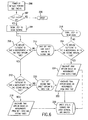
disregarded. FIG. 6 illustrates this type of operation. While FIG. 6 illustrates an
algorithm for operating one particular embodiment of the device, other
algorithms for operating the device are possible and any particular mode or
process of operation can depend on factors such as the particular embodiment
of the device and its intended uses. Furthermore, operation of the device can
be controlled electronically using a microcontroller or microprocessor, such as a
microprocessor disclosed herein.
-
In FIG. 6, operation of the device begins with a power up and initialization
phase 200, where the device performs a series of self checks after being turned
on. At decision point 202, if the self-checks are suitable, the device signals the
user to begin blowing 204 via a visual or audible signal. If the self-checks 202
fail, then the device enters an error mode 206.
-
After the user begins blowing into the device, the microprocessor (or
other data processor) checks the detected airflow in the first tube against the
pre-programmed range of optimal accuracy for the first tube to assess whether
the airflow is sufficient to take an accurate measurement of airflow in the first
tube 208. "Sufficient" airflow is understood to be a rate of airflow falling within
the range of optimal accuracy for a tube. Airflow that falls outside this range of
optimal accuracy is considered insufficient. If the airflow rate in the first tube not
sufficient, then the microprocessor sends a signal to the gate within the first
airflow tube, causing it to shut and redirect the airflow solely into the second
tube 210. If the airflow rate is sufficient, no signal is sent to the gate and the
gate remains open, allowing airflow through the first tube.
-
In either case, the microprocessor then detects whether the airflow
through the second tube is sufficient to take a measurement 212, 214. If the
airflow through both tubes is sufficient, then the microprocessor calculates the
final airflow based on measurements from both tubes 216. If the airflow is not
sufficient in either tube, then the user is instructed to blow again 218 and the
microprocessor returns to the point of detecting whether airflow through the first
tube is sufficient to take a measurement of the airflow rate in the first tube 208.
-
If the airflow through the first tube was sufficient, but the airflow through
the second tube is not sufficient, the microprocessor sends a signal to the gate
in the second tube, causing the gate to shut and the airflow from the
mouthpiece to be directed entirely into the first tube 220. The final airflow is
then calculated based on measurements from the first airflow tube 222. If the
airflow through the first tube was not sufficient to take a measurement of the
airflow rate, but was sufficient through the second airflow tube, then the final
airflow is calculated based on measurements in the second tube 224. After the
final airflow is calculated 216, 222, 224 the airflow data is directed to storage for
later retrieval and analysis 226.
-
In alternative embodiments of the device lacking an airflow director, steps
210 and 220 can be eliminated from the algorithm illustrated in FIG. 7. For
example, at step 224, the microprocessor can calculate the final airflow based
on measurements from the second tube alone and essentially ignore any data
based on measurements from the first tube, while at step 222, the
microprocessor can calculate the final airflow based on measurements from the
first tube alone and essentially ignore any data based on measurements from
the second tube.
-
The device optionally may include a thermometer or other temperature
sensor in the housing lumen and/or tubes. For example, as shown in FIG. 1,
digital thermometers 42, 44 are located within airflow tubes 30, 32. In
alternative embodiments, the temperature sensor is another type of
thermometers, a thermocouple, a thermistor, or any other suitable device. For
example (and without limitation), the illustrated digital thermometers 42, 44
measure the temperature of the user's breath, which can then be used to
estimate body temperature. In alternative embodiments, however, body
temperature is measured by a temperature sensor mounted outside the airflow
path or otherwise coupled to the device. For example, a temperature sensor
can be mounted to the mouthpiece at the proximal end of the device for
measuring the temperature of the user's lips, or a separate temperature sensor
can be placed on the user's body, such as on the forehead, and operably
connected to the device. As another example, the mouthpiece can include an
infrared thermometer for detecting the user's body temperature based on
infrared signatures within the interior of the mouth, such as a modified version of
the tympanic infrared thermometer disclosed in U.S. Pat. No. 6,149,297. In still
other alternative embodiments, temperature sensor measures the ambient
temperature outside the device, rather than the body temperature of the subject.
For example, the temperature sensor can be a thermocouple or digital
thermometer coupled to the housing in a way that allows the ambient
temperature to be measured. The temperature sensor can be coupled to or
correlated with the pulmonary airflow sensor to provide integrated data
collection from both sensors.
-
The device also can include a non-spirometric cardiopulmonary activity
sensor, such as cardiovascular or pulmonary activity detectable by other than
airflow. For example, the non-spirometric cardiopulmonary activity sensor can
utilize acoustic, optical, tactile, electrical, or other sensors to detect or measure
a parameter or characteristic of cardiovascular or pulmonary activity, including
(but not limited to) blood pressure, heart rate, patterns of heartbeat, blood gas
concentration (for example, using an oximeter to measure blood oxygen
concentration), concentration of gases in the breath during exhalation (for
example, using a detector of a specific gas, such as oxygen, nitric oxide, carbon
dioxide, or a combination thereof), respiratory pattern or rate, temperature of the
breath during exhalation, and lung sounds.
-
One specific example of a a non-spirometric cardiopulmonary activity
sensor is a pulse rate sensor, such as microphone 60 illustrated in FIGS. 1 and
4. Microphone 60 is located adjacent the distal end of device 10 and is capable
of detecting the sounds of the subject's heartbeat. Once mouthpiece 12 is
placed in the subject's mouth, microphone 60 detects sound signatures
matching a frequency and amplitude range associated with transmission of
heart sounds from the chest cavity through the throat and mouth of a subject.
For example, U.S. Pat No. 6,241,683 describes detection of respiratory sounds
and how such sounds can provide a diagnosis and/or prognosis of respiratory
disease. One feature described in that patent involves the digital filtering of
sound signals between 200 and 1000 Hz in order to remove heart and muscle
sounds, which are typically less than 200 Hz. Therefore, the sound data
collected by microphone 60 can be filtered to amplify sound signals less than
200 Hz in order to differentiate heart and muscle sounds from respiratory
sounds. Detection of such sound signatures can be conducted before, during,
or after the subject inhales or exhales through mouthpiece 12.
-
Alternatively, distal end 24 of device 10 can be placed against the chest
of the subject for recording heart beat through microphone 60, or microphone
60 can be replaced by a remote microphone operably connected to the device
via a wire lead and a microphone jack or a wireless connection.
-
In addition to measuring heart rate, microphone 60 can detect and/or
record sounds of breathing, such as raspiness, wheezing, secretion, or rales
within the lungs. Detection of such breath sounds during assessment of lung
function can assist in other medical or veterinary determinations, such as
diagnosing disease, assessing the physiological status of the subject, or
determining drug efficacy. For example, wheezing is associated with asthma,
and changes in wheezing detected by the sensor can be used as a parameter
to measure responses to therapeutic intervention, such as administration of an
anti-asthmatic medication. The presence of pulmonary rales (crackling),
associated with heart failure, can also be used as an additional piece of
diagnostic data to differentiate a purely pulmonary condition from a pulmonary
complication of an underlying myocardial compromise.
-
In some embodiments, the device is pre-programmed to detect sounds of
a particular frequency, amplitude, and/or duration associated with pulmonary
diseases or disorders. In other embodiments, the sounds detected by the
microphone are digitally recorded and stored within the device for later analysis
by a health care professional. For example, devices for recording and/or
analyzing breath sounds are described in PCT publications WO 90/04945 and
WO 99/52431, and U.S. Pat. Nos. 6,383,142; 6,241,683; and 6,168,568.
-
In other embodiments, the non-spirometric cardiopulmonary activity
sensor includes a heart monitor. For example, a simple heart monitor can
include plural electrocardiogram (EKG) electrodes operably connected to the
data processor of the device to allow integrated collection of pulmonary airflow
information and data related to the subject's heartbeat, such as heart rate or
abnormalities in heart rhythm.
-
In still other embodiments, the non-spirometric cardiopulmonary activity
sensor includes a blood oximeter, such as non-invasive blood oximeter, for
example, an infrared blood oximeter.
-
Additionally, in still other embodiments, the non-spirometric
cardiopulmonary sensor is a device that detects or monitors exhaled breath
components, including gases. For example, a nitric oxide (NO) detector is
disclosed in Shioya, T. and Swager, T.M., Chem. Comm., 1364-65 (July 2002).
This detector is a small transistor carrying an electrically conductive molecular
polymer studded with cobalt ions. NO molecules bind to the cobalt ions and
alter the conductivity of the polymer, which is then detected by the transistor.
As another example, PCT publication WO 02/17991 describes a portable
respiratory gas sensor capable of measuring the concentration of a particular
respiratory gas (for example, NO or oxygen) or other breath component (such
as glucose) in the exhalation flow pathway of a subject.
-
As illustrated in FIG 4, microphone 60 includes an optional fabric cover
62 stretched over housing lumen 22 and airflow port 24 to protect the
microphone parts within housing lumen 22. The spaces within the weave of
fabric cover 62 allow air to flow from housing lumen 22 out through airflow port
24. Additionally, airflow port 24 includes an optional set of lateral vents 64 in
fluid communication with housing lumen 22 to permit additional airflow through
airflow port 24. While the three illustrated lateral vents 64 are rectangular in
shape, vents of other shapes or sizes are possible, such as arcuate, circular,
triangular, hexagonal, or rhomboid lateral vents. Also, a different number of
lateral vents can be defined in the housing, such as one, two, four, five, six or
more lateral vents. In alternative embodiments, the distal end of the housing
lumen does not have the protective fabric cover and/or the lateral air vents.
-
Microphone 60 can be used to detect other physiological sounds in the
subject's body and those sounds can be stored in digital memory for later
analysis. For example, microphone 60 can be placed against the subject's
abdomen for recording gastrointestinal sounds, or microphone 60 can be
replaced with an equivalent microphone in remote connection (for example, by a
wireless connection or through a wire lead) to the device, and the remote
microphone can be placed against the subject's abdomen. Similarly,
microphone 60 (or its equivalent) can be placed elsewhere on the subject's
body, such as on a joint for detecting popping or grinding within the joint. As
another example, microphone 60 (or its equivalent) can be placed over a blood
vessel, such as the major blood vessels of the neck, to detect blood flow
through the vessel. Abnormal blood flow sounds, or differential blood flow
through similar vessels (for example, the right and left carotid arteries), can
indicate an obstruction of a blood vessel, such as atherosclerosis or a blood
clot.
-
Additionally, microphone 60 can record dictation from the subject or other
user of the device, such as a health care professional. For example, a subject
using the device at home can record information about the date and time of use,
or the subject can relate basic information related to the use of the device, such
as recording a short note like "I feel dizzy now," or "My heart feels like it is
beating faster." As another example, a physician using the device in a clinic can
record notes about the patient and transfer those notes with the data later
transmitted by the device.
-
In addition to the microphone, device 10 can include an optional signaler,
such as a small speaker, one or more warning lights (such as LED's), an LCD
screen, or other mechanism for providing a visual or audible signal to the user.
In particular embodiments, the signaler is an LCD screen on the external
surface of the device that can display particular pre-programmed messages. In
other particular embodiments, the signaler is a small speaker that can audibly
transmit messages stored as pre-programmed digital audio files. For example,
the signaler can include pre-programmed messages for operating the device or
performing a PFT, such as "Error―failure during initialization―please restart,"
or "Blow harder," "Blow softer," "Blow as hard as you like," or "Keep blowing until
your lungs feel empty." In still other embodiments, the signaler is a plurality of
different colored LEDs and a guidebook that includes messages corresponding
to the pattern of lit or unlit LEDs.
-
In some embodiments, device 10 also includes a light source (not shown)
mounted on the outside of housing 14 or located within housing lumen 22,
which can be used to illuminate the inside of the subject's mouth and throat.
For example, a physician or veterinarian using the device on a subject could
obtain cardiopulmonary data about the subject, then use the light source to
examine the interior of subject's mouth and throat. Any suitable light source can
be used, such as a light bulb or LED.
-
In certain embodiments, the device includes, or is coupled to, a digital
camera or digital video camera. As just one example, an optical fiber with a
lens can be mounted within the housing lumen, passed through the wall of the
housing, and coupled to a digital camera located outside the device. Using
such embodiments, digital images of the interior of the subject's mouth and
throat can be acquired before, during, or after the device is used to gather
cardiopulmonary data from a subject. These digital images can provide
additional information about the subject's physiological condition.
-
In some embodiments, the device includes a removable prophylactic
cover, such as a snugly fitting plastic film or bag, to enhance the sterilization of
the device, or to resist dirt and other contaminants. For example, embodiments
used in hospitals can utilize replaceable mouthpieces, which are disposed after
each use by a patient, and the replaceable prophylactic cover over the housing
to inhibit transmission of viruses and bacteria among patients. As another
example, embodiments used by veterinarians in the field can employ
replaceable covers to inhibit contamination by dirt, mud, or animal body fluids
and to assist in cleaning the device―a soiled cover can simply be removed and
replaced by a clean one.
-
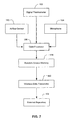
FIG. 6 illustrates one embodiment for integrating or collating data
obtained by various sensors within the device. In this embodiment, pulmonary
airflow sensor 150, temperature sensor 152, and non-spirometric
cardiopulmonary activity sensor 154, are operably connected to a data
processor 156.
-
The dataprocessor 156 include a digital microprocessor, microcontroller,
central processing unit, or other digital processing device. Particular examples
of data processor include the line of Motorola MPC8XXX Integrated Host
Processors (Motorola, Inc., Shaumburg, IL); the AMD Athlon™ XP, Athlon™ 4,
and Duron™ processors (Advanced Micro Devices, Inc., Huntsville, AL); and the
Mobile Intel® Pentium® 4 Processor-M, Mobile Intel® Pentium® III Processor-M,
and Intel® Mobile Celeron® processors (Intel Corporation, Hillsboro, OR).
-
The data processor, such as a microprocessor, allows integrated
collection of data from all sensors within the device. For example, as illustrated
in FIG. 6, data regarding pulmonary airflow (collected via the airflow sensor), the
subject's body temperature (obtained via the digital thermometer), and non-spirometric
cardiopulmonary activity, such as cardiac pulse rate (obtained via
the microphone), can be integrated into a single data set.
-
Integrated data collection offers the advantage of measuring a subject's
pulmonary function and some other physiological characteristic simultaneously,
or nearly simultaneously, to provide a faster or more accurate physiological
assessment of the subject. Since cardiovascular and pulmonary functions are
interrelated, collecting and integrating data from each system can assist in the
diagnosis of disease or conditions affecting the vascular system and lungs.
-
Additionally, measuring body temperature can provide information that
alters conclusions based on spirometric data alone or in combination with non-spirometric
cardiovascular information. For example, the presence of both a
fever and abnormal spirometric data indicating reduced lung function can signal
an acute infection, such as pneumonia, while the lack of a fever can indicate
some non-infectious disease, such as emphysema. Acute infection can be
assessed using other devices or methods. For example, nitric oxide (NO) is
produced when a subject's immune system fights infection. Therefore,
detecting increased NO levels in a subject's breath can signal infection, such as
pneumonia or exposure to a biological-warfare agent.
-
The importance of the diagnostic interrelationship of spirometry and non-spirometric
data is illustrated, for example, by a subject (such as a human
patient) who presents with shortness of breath. Such a symptom in an
individual with pre-existing asthma or COPD is sometimes mistakenly
diagnosed as an exacerbation of the underlying pulmonary condition, when in
fact it is a myocardial problem, such as heart failure. However, by monitoring
both spirometric and non-spirometric data, such as heart sounds or
electrocardiographic data, such an incorrect diagnosis can be avoided and
appropriate (and often life-saving treatment) initiated. For example, if shortness
of breath is caused by heart failure with pulmonary edema in a person with pre-existing
asthma, a diagnosis of heart failure can be detected by the presence of
an S3 and/or S4 heart sound detected by the microphone. Alternatively, EKG
changes associated with myocardial ischemia can detect an underlying
myocardial condition that may present as shortness of breath.
-
The diagnostic interrelationship of spirometry and non-spirometric data
also is illustrated by a subject having other breathing difficulties, such as
hyperventilation. For example, lower blood oxygen concentration in healthy
patients will signal the central nervous system to stimulate the lungs and induce
a higher respiratory rate. Therefore, combining blood oximetry and spirometry
data can indicate a problem of the central nervous system of a patient with low
blood oxygen concentration and low respiratory rate. Tachycardia (variations in
heart rate) is often seen in patients who are hypoxic. Collecting spirometric data
and measuring heart rate at the same time can help ascertain whether the
tachycardia and hypoxia are due to a pulmonary obstruction (such as asthma
detected by decreased FEV1), or some non-pulmonary cause for hypoxia, (such
as anemia or reduced oxygen carrying capacity of the blood). As another
example, an embodiment of the device having a blood oximeter (such as a
pulse oximeter or other sensor that measures oxygenated hemoglobin in blood)
can integrate pulmonary airflow data with blood oxygen saturation data to
measure the efficiency of oxygen absorption through the lungs into the blood.
Low efficiency of absorption (as reflected in a low blood oxygen saturation, such
as a saturation of less than about 95% or 90%) can indicate an obstruction in
the lungs, apnea, or other condition inhibiting oxygen uptake. As still another
example, detecting blood gas concentrations or respiratory gas concentrations
can differentiate different diseases or conditions, such as anxiety, induced
hyperventilation, asthma, infection, COPD, respiratory alkalosis, or drug
overdose (which can inhibit respiratory drive and induce apnea). In another
example, excessive loss of CO2 in exhaled air can indicate hyperventilation and
associated respiratory alkalosis.
-
Once collected and/or integrated, the data can be transferred to data
storage 158, such as the random access memory (RAM) illustrated in FIG. 6.
Other types of data storage include a removable memory card, such as a flash
memory card, or a small hard drive. In alternative embodiments, the data
storage is located apart from the device and the device is operably connected to
the data storage. For example, and without limitation, the data storage can be
an external disk drive, CD-RW drive, or DVD drive in wireless connection to the
data processor, or the device can include a data port for connecting the data
processor to external data storage via a cable or other wired connection.
-
Additionally, the data storage can include a set of pre-programmed
parameters. For example, a unique identifier for a particular patient can be pre-programmed
into a set of read-only memory (ROM). After data is collected and
stored within the device, such as being stored within internal RAM, the pre-programmed
information can be transmitted along with the collected data. In
addition to the unique identifier, pre-programmed information can include any
other useful information, such as a timestamp that records the date and time of
each use of the device; information about the device features, model and
manufacturer; calibration data; or physiological and demographic details about
the user, for example, age, height, weight, gender, residence address,
citizenship, past medical conditions, or occupation.
-
Data collected by the device can be securely stored by the device or
some external repository. For example, the data can be password protected, or
the device itself can be programmed to require a password prior to operation. In
particular embodiments, the data is encrypted during or after collection.
-
Also shown in FIG. 6 is data transmitter 160 that transfers data from the
device 10 to an external repository 162. The specific data transmitter 160
chosen for a particular embodiment can depend on several factors, such as the
sophistication of the user, the environment in which the device will be used (for
example, a clinical setting versus home use), the equipment and technology
available for connecting the device to the external repository, and the amount of
data expected to be transferred. In the embodiment illustrated in FIG. 1, data
transmitter 160 is a wireless data transmitter (not shown), such as a
radiofrequency or infrared (IR) data transmitter. Alternative embodiments utilize
other types of data transmitters, such as a wire or cable directly connecting the
device to the external repository or a docking station for the device where the
docking station is itself connected to the external repository. FIG. 5 illustrates
such an alternative embodiment showing device 10 with docking interface 100
adapted from the docking interface of a Handspring™ Visor Platinum
(Handspring, Inc., Mountain View, CA) handheld organizer. The embodiment
illustrated in FIG. 5 is placed in its associated docking station (not shown),
which is connected to a computer, for transfer of its data to the computer in a
manner similar to the synchronization operation of Handspring™ Visor Platinum.
-
In some embodiments, the external repository is a standalone computer,
such as a laptop, handheld, or portable computer, or a network server. For
example (and without limitation), the device can be used in a hospital setting
with a nurse or clinician carrying a handheld or laptop computer wirelessly
connected to the device. The nurse or clinician can obtain cardiopulmonary
data from several individual patients, store the information in the handheld
computer, and later download this information to the hospital's centralized
patient database. Alternatively, the device can be wirelessly connected to a
central server on the hospital's computer network, and the information collected
by the nurse or clinician can be transferred directly to that server and
incorporated into the centralized patient database. As another example, a
person can use the device at home to collect physiological information over a
period of time, such as a few days, a week, a month, or even longer. That
person can connect the device to a home computer (via a wireless connection,
a docking station, a data cable, or other suitable connection) and download the
data from the device to the home computer.
-
In alternative embodiments, the external repository is a database housed
on a larger computer network, such as a wide area network (WAN) or the
Internet. For example, a person using a device at home as part of a clinical trial
or treatment regimen can transmit data from the device directly to a clinician
over the Internet via email or to a centralized database via an Internet browser
interface. As another example, a person with a pulmonary disorder undergoing
evaluation or a treatment regimen can use the device during daily activities,
then transmit data from the device to an Internet database via a home
computer. If the device is designed for use with a docking station (similar to the
embodiment illustrated in FIG. 5), the user can connect the docking station to a
home computer, establish a connection from the computer to the Internet, place
the device in the docking station, and transmit data from the internal memory of
the device to a centralized database on an Internet server or other host
computer.
-
In some embodiments, a software interface for downloading data from
the device is included as part of the external repository. For example, in the
clinical embodiment described above, the handheld or laptop computer carried
by the nurse (or other clinician) can include an interface for connecting to a
patient's device, downloading the data stored on the device, and organizing the
data once it is transferred to the computer. As another example, a person
independently using the device can load a similar interface onto a home
computer. Using the interface, he can then establish a data connection
between a computer and the device (for example, through a docking station),
establish another connection between a computer and a remote computer or
database (for example, over the Internet), and transfer the stored data from the
device to that remote computer or database. In addition to providing
instructions for using the device and transferring data to an external repository,
the software interface can include a feature to allow programming and storage
of information, such as a unique identifier and patient information. Such
programming provides an alternative to programming information into ROM
housed within the device, as described above.
-
The device can be used in any appropriate setting to gather physiological
information about a subject. In some embodiments, the device is used in a
hospital (including a veterinary hospital) or other clinical setting for gathering
relevant health information about a subject. In particular embodiments where
the subject is incapable of personally using the device (for example, an
unconscious human patient or dog in a veterinary hospital), the mouthpiece of
the device can be altered to include a facial mask for fitting over the nose and/or
mouth of the subject, or the mouthpiece can be designed to be adapted to a
preexisting facial mask. Conscious human subjects can be instructed to use the
device independently, or a nurse or other clinician can visit a patient periodically
with the device. In the case of unconscious or infirm subjects, or non-human
subjects, devices with mouthpieces adapted to fit breathing tubes or masks can
be operated by nurses or other clinicians to obtain cardiopulmonary data from
those subject.
-
In other embodiments, the device is used outside a clinical setting, such
as part of a program for monitoring or treating a pulmonary condition or disease.
For example, the device can be used to periodically monitor a person at risk for
developing cystic fibrosis, or to monitor the response of an asthmatic person to
a particular medication or other treatment. The collected information can be
analyzed to determine the onset of cystic fibrosis or effectiveness of an asthma
medication based on the person's heart rate, respiratory rate, and spirometric
performance (for example, FVC, PEF, and FEV1).
-
In some embodiments, the device provides feedback information during,
or soon after, administration of a medication. For example, the device can be
used by a hospitalized person during intravenous administration a drug to treat
pleursy. Detection of increased airflow and reduced rales can indicate that the
drug is having some effect on the pleursy.
-
In particular embodiments, the device includes, or is operably coupled to,
an applicator for administration of a medication or other bioactive composition,
such as a metered dose inhaler (MDI), a transdermal applicator, or other device
capable of administering a composition to the subject. For example, an
embodiment of the device which includes an MDI in fluid connection with the
housing lumen can be used to both administer an asthma medication (during
inhalation) and monitor the effectiveness of that medication based on changes
in cardiopulmonary status. For example, if a dose of a beta antagonist is
administered to an asthma patient, and FEV1 does not subsequently improve in
a clinically significant manner, then a subsequent dose of medicine can be
administered from the MDI, as long as the dosage does not exceed a
predetermined maximum dosage. As another example, the bio-sensor can be
operably coupled to a digitally controlled composition delivery device. For
example, U.S. Pat. Nos. 5,894,841 and 6,196,218 describe dispensers for
inhalational administration of a bioactive composition. As another example,
U.S. Pat. No. 6,165,155 describes a low-profile automatic drug delivery system
for transdermal or subcutaneous delivery of a bioactive composition. In such an
embodiment, cardiopulmonary data about a subject is collected by the bio-sensor
and digitally transferred or transmitted to the delivery device. The
delivery device then uses the data, transferred or transmitted by the bio-sensor,
to control the administration of a bioactive composition, such as a medication.
Based on the cardiopulmonary data transmitted by the bio-sensor, the delivery
device can alter the delivery of the composition―for example, by changing the
rate of delivery, total amount delivered, method of delivery, or particle size of the
composition delivered―during administration of the bioactive composition.
Thus, the combination of the bio-sensor and delivery device offers the capability
to collect bio-feedback information (by the bio-sensor) during or following
administration of medication or other bioactive composition (by the pulmonary
delivery apparatus).
-
Alternatively, the device can be used to collect baseline data for
comparison with data obtained from different subjects, or data obtained from the
same subject at a later time, such as later in the subject's life. Thus, data
obtained via the device can be pooled, such as data obtained from a single
subject over time or data obtained from multiple subjects.
-
In some embodiments, the device serves as an easy-to-use diagnostic
tool. For example, a person using the device at home can transmit
cardiopulmonary data, which is encrypted to protect the person's privacy, over
the Internet to a centralized database. That data can be compared to baseline
data obtained from other people―even several hundred or thousand or million
people. A diagnostic report based on that comparison, including instructions to
consult with a medical professional, can then be sent back to the user via mail,
email, or facsimile. Alternatively, the device can include instructions to
telephone a consultant who would relate the results of the report. As another
example, the device can be preprogrammed to alert the user to seek medical
advice if the collected data meets certain criteria, such as wheezing and low
breathing rate coupled with a high body temperature, which could indicate
infection in the lungs.
-
The data collected by the device can be archived for long-term analysis.
Data from a single subject or multiple subjects obtained repeatedly over a
period of time (for example, several days, weeks, months, or years) can be
archived and periodically analyzed to detect any abnormalities. This archival
feature provides the benefit of detecting a decline in pulmonary ability that might
otherwise go unnoticed, or can be used in clinical trials to measure and track the
efficiency of a drug. For example, a person with an upper respiratory infection
or influenza can take daily or twice-daily measurements of cardiopulmonary
function, and transfer the collected data via the Internet to a centralized
database. This collected data can then be periodically analyzed, by a human or
software agent, to detect a downward trend in pulmonary function. If the
person's lung function (measured via spirometric data) falls beneath a certain
threshold, a warning can be delivered to that person and/or the person's
physician (such as via email) stating that the person should seek additional
medical attention (for example for possible pneumonia). While the person might
not notice a gradual decline in breathing ability or a gradual increase in body
temperature, trend analysis of the archived cardiopulmonary data obtained from
the subject can provide an early indicator of a decline in cardiopulmonary
function caused by infection, chronic disease, or other physiological condition.
Furthermore, data from multiple subjects can be obtained over time, archived,
and later analyzed for population trends, such as trends within a population of
subjects expected to be at a higher risk for developing a cardiopulmonary
disease or condition, such as a respiratory disease. For example,
cardiopulmonary data periodically obtained from persons living near a smelter,
refinery, or living in some other industrial area, can be archived in a database
and several years of data can be analyzed to detect trends in the development
or exacerbation of asthma or other respiratory disease. As another example,
livestock populations (such as cattle and horses) near wildlife populations (such
as deer and elk) can be periodically monitored with the bio-sensor to detect
early signs of disease transmission from wildlife. The bio-sensor offers a non-invasive
method of collecting cardiopulmonary data from a large population of
livestock. Those animals exhibiting signs of infection (such as fever and/or
impaired respiration) can then be identified for further, more specific tests, such
as blood tests that detect antigens to specific infectious agents.
-
Additionally, data collected by a number of devices can be integrated into
a database for further processing. For example, data from a population of
human users can be collected into a large database and later mined for
particular trends or clusters of information. In specific embodiments, a database
is coupled to analysis software to provide an expert system for guiding
clinicians. For example, a person using the device at home while recovering
from a pulmonary embolus could transmit data collected by the device to a
centralized database. Analysis software would then process this transmitted
data, compare it against information in the large database, and transmit a report
on the person's general health to the person's treating physician.
-
The sensor device for sensing cardiopulmonary activity, as described
above, can be made or manufactured in any appropriate manner. In some
embodiments, an elongated housing having a proximal end, a distal end, and a
lumen is obtained, and an airflow sensor is mounted inside the housing lumen.
A data processor, such as a microprocessor, is added and coupled to the airflow
sensor. A non-spirometric cardiopulmonary activity sensor also can be added to
the housing and operably coupled to the data processor. Such a sensor device
is then capable of integrated collection of cardiopulmonary data obtained via the
airflow sensor and the non-spirometric cardiopulmonary activity sensor.
-
In some embodiments, the method of making or manufacturing the
sensor device includes adding other features described above. For example,
plural airflow tubes, such as a first airflow tube and a second airflow tube, can
be displaced within the housing lumen. As described above, the diameters of
the plural airflow tubes may be identical, substantially similar, or different. As
another example, a temperature sensor can be coupled to the data processor.
Such a device is capable of integrated collection of physiological data obtained
via the airflow sensor, the cardiopulmonary activity sensor, and/or the
temperature sensor.
-
Having illustrated and described the principles of the invention by several
embodiments, it should be apparent that those embodiments can be modified in
arrangement and detail without departing from the principles of the invention.
Thus, the invention includes all such embodiments and variations thereof, and
their equivalents.