INCORPORATION BY REFERENCE
The disclosure of Japanese Patent Application No. 2004-119152 filed on April 14, 2004
including the specification, drawings and abstract is incorporated herein by reference in its
entirety.
BACKGROUND OF THE INVENTION
1. Field of Invention
The invention relates to a wheel state adjustment system and a wheel state adjustment
method for adjusting a predetermined quantity of state of a wheel, which may be, for
example, an internal air pressure of a tire.
2. Description of Related Art
As noted in Japanese Patent Application Publication No. JP-A-7-137515 and No. JP-A-2003-94917,
it is desirable to monitor various quantities of state of a wheel, such as an
internal air pressure of a tire, in order to maintain the wheel in an appropriate state and
achieve comfortable running of a vehicle. Accordingly, various related methods have been
proposed for monitoring wheel quantities of state, like changes in the internal air pressure
within the tire.
Many of the disclosed systems for monitoring wheel quantities of state and maintaining
them appropriately, detect a wheel quantity of state such as the internal air pressure of the tire
by using (a) sensors attached to a vehicle body, or (b) sensors provided in integrated units
with vehicle instruments attached to the vehicle body.
However, recently, systems are being widely adopted that use sensors provided on each
wheel to detect the respective wheel quantity of state such as the internal air pressure of the
tire, and then transmit the detection results to an Electronic Control System (ECU), or the
like, provided on the vehicle body. Such systems are epitomized by Tire Pressure Monitoring
Systems (TPMS). In these systems, the sensors provided on each wheel are usually capable
of switching between different operating modes depending on the wheel quantity of state.
For example, some TPMS utilize sensors that switch between (a) infrequent detection of the
wheel quantity of state at normal times, and (b) frequent detection of the wheel quantity of
state when it is determined that an abnormality is likely to have occurred. By adopting such a
configuration, it is possible to improve safety.
However, the sensors provided on the wheels often use a battery provided on each
wheel as an energy supply rather than a battery provided on the vehicle body. Accordingly,
in order to enable the sensors to be operated over extended periods using the respective wheel
batteries, it is important to operate the sensors efficiently and reduce energy consumption.
For example, some TPMS pro-actively adjust the tire internal air pressure to an appropriate
level to suit the road being run along. With such systems, however, there is a possibility that
use of this pro-active adjustment of the tire internal air pressure will cause the sensors to
operate improperly and frequently detect the wheel quantity of state and transmit the
detection results even when there is no likelihood that the wheel is in an abnormal state.
However, as will be apparent, from the point of view of reducing energy consumption it is
clearly undesirable if the sensors operate improperly and detect the wheel quantities of state
more than necessary.
SUMMARY OF THE INVENTION
The invention was conceived of while taking into consideration the above described
problems, and it is an object thereof to provide a wheel state adjustment system and wheel
state adjustment method that enable a predetermined quantity of state of a wheel to be
appropriately monitored and adjusted.
A first aspect of the invention provides a wheel state adjustment system that includes: a
wheel state monitoring means which monitors a predetermined quantity of state of a wheel,
and which transmits a notification when an abnormality of the wheel occurs; and a wheel
state adjustment means that adjusts the quantity of state of the wheel. In the first aspect, the
wheel state monitoring means reduces a transmission frequency at which the notification
related to the occurrence of an abnormality of the wheel is transmitted when the wheel state
adjustment means is adjusting the predetermined quantity of state of the wheel.
According to the first aspect, it is possible to (i) monitor the predetermined quantity of
state of the wheel, (ii) transmit the notification related to the occurrence of an abnormality,
and (iii) adjust the predetermined quantity of state of the wheel. Further, by reducing the
transmission frequency of the notification related to the occurrence of an abnormality of the
wheel while the wheel state adjustment means is adjusting the predetermined quantity of state
of the wheel, it is possible to reduce the amount of energy that is consumed by transmitting
the notification related to the occurrence of an abnormality of wheel.
Note that, the term "predetermined quantity of state of the wheel" as used in this
specification includes any characteristic or factor related to the state or condition of the
wheel. An example of such a predetermined quantity of state is a tire internal air pressure of
a tire of wheel. Further, the phrase "an occurrence of an abnormality of the wheel" indicates
a concept that includes times when there is a high probability that an abnormality of the
wheel has occurred. In addition, the phrase "transmit a notification related to the occurrence
of an abnormality of the wheel" indicates both (a) times when the notification related to the
occurrence of an abnormality of the wheel is transmitted directly, and (b) times when the
notification related to the occurrence of an abnormality of the wheel is transmitted indirectly
by manipulating the characteristics of the transmission frequency, or the like.
The first aspect may be configured such that, when the wheel state adjustment means is
adjusting the predetermined quantity of state of the wheel, the wheel state monitoring means
reduces the transmission frequency at which the notification related to the occurrence of an
abnormality of the wheel is transmitted by stopping transmission of the notification related to
the occurrence of an abnormality of the wheel.
Moreover, the first aspect may be configured such that, when the wheel state
adjustment means is adjusting the predetermined quantity of state of the wheel, the wheel
state monitoring means reduces the transmission frequency at which the notification related
to the occurrence of an abnormality of the wheel is transmitted by changing a determination
condition for determining whether an abnormality of the wheel has occurred. It should be
noted that, in a normal case, there are occasions when adjustment of a predetermined quantity
of state by a wheel state adjustment means causes a wheel state monitoring means to
mistakenly determine that an abnormality of the wheel has occurred, even though no such
abnormality of the wheel actual exists. However, according to the present wheel state
adjustment system, it is possible to effectively inhibit such mistaken determinations from
being made by appropriately changing the determination condition for the occurrence of an
abnormality of the wheel.
According to the first aspect and a modified form thereof, the wheel state adjustment
means may notify the wheel state monitoring means that the wheel state adjustment means is
adjusting the predetermined quantity of state of the wheel by manipulating the predetermined
quantity of state of the wheel in a predetermined manner. By adopting such a configuration,
it is possible to notify the wheel state monitoring means that the wheel state adjustment
means is adjusting the predetermined quantity of state of the wheel by using a simple method,
namely, by manipulating the predetermined quantity of state of the wheel using the wheel
state adjustment means.
Further, according to another modified form of the first aspect, the wheel state
adjustment means notifies the wheel state monitoring means that the predetermined quantity
of state of the wheel is being adjusted by manipulating the predetermined quantity of state
such that the predetermined quantity of state exhibits a type of behavior that is not normal. If
this configuration is utilized, it is possible to clearly distinguish between (i) the behavior of
the predetermined quantity of state of the wheel at normal times, and (ii) a specific type of
behavior of the predetermined quantity of state of the wheel that is caused by adjustment of
the predetermined quantity of state of the wheel. As a result of this clear distinction, it is
possible to inhibit the two types of behavior from being confused. Note that, the phrase "a
type of behavior that is not normal" indicates a type of behavior that is, for example, not
normally exhibited when the wheel is being used and run in everyday conditions. Further,
this "type of behavior that is not normal'' is distinguishable from behavior of the
predetermined quantity of state of the wheel that is exhibited as a result of damage of the
wheel or its running environment.
According to the first aspect and another modified form thereof, the wheel state
adjustment means may adjust the predetermined quantity of state of the wheel by referring to
a monitoring result for the predetermined quantity of state of the wheel that is obtained from
the wheel state monitoring means. By adopting such a configuration, it is possible to perform
the adjustment of the predetermined quantity of state of the wheel in line with changes in the
predetermined quantity of state of the wheel.
Moreover, according to the first aspect, the wheel state adjustment means may adjust
the predetermined quantity of state of the wheel by referring to a speed of a vehicle to which
the wheel is attached. Adoption of this configuration enables the predetermined quantity of
state of the wheel to be adjusted safely in line with the vehicle speed.
Further, according to the first aspect and another modified form thereof, the
predetermined quantity of state of the wheel may be a tire internal air pressure of a tire of the
wheel. Note that, the tires of an automobile are in contact with the road surface, and are
easily damaged or affected by the environment. Therefore, it is important to maintain the tire
internal air pressure at an appropriate level. The present wheel state adjustment system takes
this requirement into consideration, and makes it possible to appropriately monitor and adjust
the tire internal air pressure.
The first aspect and another modified form thereof may also be provided with a
warning device that generates a warning based on the notification related to the occurrence of
an abnormality of the wheel that is obtained from the wheel state monitoring means.
Utilization of this configuration makes it possible to easily inform the driver or other vehicle
user about the occurrence of an abnormality of the wheel by generating the warning related to
the occurrence of the abnormality of the wheel.
It should be noted that the scope of the invention is taken to include other suitable
combinations of the above described elements, other modifications thereof, and any other
systems or devices that, despite different wording or phraseology, realize the invention. All
such combinations, modifications, devices and systems are taken to fall within the scope of
the invention receiving patent protection under the present application.
According to the invention, it is possible to both monitor the predetermined quantity of
state of the wheel using the wheel state monitoring means and adjust the predetermined
quantity of state of the wheel using the wheel state adjustment means while the transmission
frequency of the notification related to the occurrence of an abnormality of the wheel is
reduced when the predetermined quantity of state of the wheel is being adjusted by the wheel
state adjustment means. Accordingly, it is possible to reduce the amount of energy that is
consumed by transmitting the notification related to the occurrence of an abnormality of the
wheel.
A second aspect of the invention provides a wheel state adjustment method for a wheel
state adjustment system. This method includes the steps of: monitoring a predetermined
quantity of state of a wheel and transmitting a notification when an abnormality of the wheel
occurs; and adjusting the predetermined quantity of state of the wheel. The method further
includes a step of reducing a transmission frequency at which the notification related to the
occurrence of an abnormality of the wheel is transmitted is reduced when the predetermined
quantity of state of the wheel is being adjusted.
The second aspect may be configured such that, when the predetermined quantity of
state of the wheel is being adjusted, the transmission frequency at which the notification
related to the occurrence of an abnormality of the wheel is transmitted is reduced by stopping
transmission of the notification related to the occurrence of an abnormality of the wheel.
Moreover, the second aspect may be configured such that when the predetermined
quantity of state of the wheel is being adjusted, the transmission frequency at which the
notification related to the occurrence of an abnormality of the wheel is transmitted is reduced
by changing a determination condition for determining whether an abnormality of the wheel
has occurred.
Further, according to the second aspect and a modified form thereof, the monitoring
step may monitor whether the predetermined quantity of state of the wheel is being adjusted
based on whether the predetermined quantity of state is manipulated in a predetermined
manner.
According to another modified form of the second aspect, the monitoring step monitors
whether the predetermined quantity of state of the wheel is being adjusted based on whether
the predetermined quantity of state of the wheel is changed such that the predetermined
quantity of state exhibits a type of behavior that is not normal.
Further, according to the second aspect and another modified form thereof, the
adjusting step of the predetermined quantity of state of the wheel may be performed by
referring to a monitoring result for the predetermined quantity of state of the wheel.
In addition, the second aspect and another modified form thereof may be configured
such that the adjusting step of the predetermined quantity of state of the wheel is performed
by referring to a speed of a vehicle to which the wheel is attached.
Moreover, the second aspect and another modified form thereof may be configured
such that the monitoring step of the predetermined quantity of state of the wheel is based
upon measurement of a tire internal air pressure of a tire of the wheel.
Further, the second aspect and another modified form thereof may further include a step
of generating a warning based on the notification related to the occurrence of an abnormality
of the wheel.
BRIEF DESCRIPTION OF THE DRAWINGS
The foregoing and further objects, features and advantages of the invention will become
apparent from the following description of preferred embodiments with reference to the
accompanying drawings, wherein like numerals are used to represent like elements and
wherein:
DETAILED DESCRIPTION OF EMBODIMENTS
Hereinafter, preferred, exemplary embodiments of the invention will be described with
reference to the drawings.
First Embodiment
FIG. 1 shows the overall configuration of a vehicle 10 according to the first
embodiment. This vehicle 10 is provided with a mechanism for monitoring a tire internal air
pressure of each tire (not shown), and a mechanism for adjusting each tire internal air
pressure. The vehicle 10 includes a vehicle body 12, and wheels 14 that are provided at the
left and right sides of the front and rear of the vehicle body 12.
A vehicle body side communication device 16; a warning device 18; an air tank 19; an
air pump 20 that is connected to the air tank 19; a tire air pressure indicator 21; four air
adjustment electromagnetic valves 24 that are connected to the air pump 20 via an air passage
22; and an Electronic Control Unit (ECU) 26 are mounted in the vehicle body 12. The ECU
26 is connected to the vehicle body side communication device 16, the warning device 18,
the tire air pressure indicator 21, the air pump 20, and the four air adjustment electromagnetic
valves 24. Note that, for the sake of explanatory simplicity, the following description will
focus on the example of one of the wheels 14, although the same explanation applies to all
four wheels 14.
The wheel 14 includes the tire that is filled with air, and a wheel body (not specifically
shown) that supports the tire. The wheel 14 is provided with a tire pressure adjustment
portion 28 that is connected via the air passage 22 to the air adjustment electromagnetic valve
24; a pressure detection sensor 30; a transmission mode determination device 32 that is
connected to the pressure detection sensor 30; and a wheel side communication device 34 that
is connected to the transmission mode determination device 32. The pressure detection
sensor 30, the transmission mode determination device 32, and the wheel side communication
device 34 operate using electric energy stored in a battery (not shown) mounted in the wheel
14. The pressure detection sensor 30, the transmission mode determination device 32, and
the wheel side communication device 34 that are provided in the wheel 14 may be formed as
an integral unit or as separate units.
The tire pressure adjustment portion 28 functions as a valve connecting the inside of the
tire with the air passage 22, and (a) fills the tire with air provided from the air adjustment
electromagnetic valve 24, and (b) transmits the air within the tire to the air adjustment
electromagnetic valve 24. The tire pressure adjustment portion 28 adjusts the air pressure
within the air passage 22 and the air pressure within the tire so that the two air pressures are
substantially equal to each other.
The pressure detection sensor 30 is configured as a Tire Pressure Monitoring System
(TPMS) that can individually monitor the tire internal air pressure of the tire. The pressure
detection sensor 30 periodically detects the tire internal air pressure, and transmits the
obtained detection results to the transmission mode determination device 32. The pressure
detection sensor 30 according to this exemplary embodiment detects the tire internal air
pressure, and transmits the obtained detection result to the transmission mode determination
device 32 at a rate of once every fifteen seconds.
The transmission mode determination device 32 determines a transmission mode of the
wheel side communication device 34 based on the detection result received from the pressure
detection sensor 30. More specifically, the transmission mode determination device 32
determines the transmission mode of the wheel side communication device 34 by comparing
(i) a change amount for a predetermined time period of the tire internal air pressure, and (ii) a
pre-set transmission mode determination threshold value. The above mentioned change
amount is derived from the detection result from the pressure detection sensor 30.
In this embodiment, the wheel side communication device 34 has two transmission
modes, namely, (i) a normal transmission mode in which the detection result of the pressure
detection sensor 30 is transmitted infrequently at a rate of once every minute, and (ii) an
emergency transmission mode in which the detection result of the pressure detection sensor
30 is transmitted frequently at a rate of once every fifteen seconds. When the change amount
for the predetermined time of the internal air pressure is a value that is equal to or less than
the transmission mode determination threshold value, it is determined that the internal air
pressure of the tire is normal. Accordingly, the transmission mode determination device 32
determines that the normal transmission mode should be used as the transmission mode. On
the other hand, when the change amount for the predetermined time of the internal air
pressure is a value that is more than the transmission mode determination threshold value, it
is determined that there is a possibility that the internal air pressure of the tire is abnormal.
As a result, the transmission mode determination device 32 determines that the abnormal
transmission mode should be used as the transmission mode.
In the case that the tire internal air pressure is pro-actively adjusted to suit a running
environment in line with a command from a vehicle driver, or other vehicle user (as will be
described later), when the air adjustment electromagnetic valves 24, etc., are adjusting the tire
internal air pressure, the transmission mode determination device 32 will have a tendency to
control the transmission frequency at which the wheel side communication device 34
transmits the detection results from the pressure detection sensor 30, and the like, to be less
than that at normal times. Accordingly, the transmission mode determination device 32 of
this embodiment reduces the transmission frequency of the wheel side communication device
34 by changing the transmission mode determination threshold value (which is the condition
for determining whether an abnormality of the wheel 14 has occurred), when the air
adjustment electromagnetic valves 24, etc., are adjusting the tire internal air pressure to suit
the running environment.
More particularly, when the transmission mode determination device 32 determines that
the tire internal air pressure is not being adjusted, the transmission mode is determined using
a first transmission mode determination threshold value. On the other hand, when it is
determined that the tire internal air pressure is being adjusted, the transmission mode is
determined using a second transmission mode determination threshold value that is higher
than the first transmission mode determination value. When the second transmission mode
determination threshold value is used, as compared to when the first transmission mode
determination threshold value is used, the frequency of switching to the emergency
transmission mode from the normal transmission mode is reduced due to the higher threshold
value. As a result, it is possible to reduce the overall transmission frequency of the wheel
side communication device 34.
The transmission mode determination device 32 is configured such that the first
transmission mode determination threshold value is returned to after a predetermined time
has elapsed after use of the second transmission mode determination threshold value. It is
preferable if this predetermined time is set such that the second transmission mode
determination threshold value is utilized by the transmission mode determination device 32
when the air adjustment electromagnetic valve 24, etc. are adjusting the tire internal air
pressure to suit the running environment.
The transmission mode determination device 32 determines whether or not the air
adjustment electromagnetic valve 24, etc. are adjusting the tire internal air pressure to suit the
running environment based on the detection result of the pressure detection sensor 30. In this
embodiment, as will be described hereinafter, an "indication signal" that the tire internal air
pressure is being adjusted by the air adjustment electromagnetic valves 24, etc., to suit the
running environment is sent to the devices on the wheel 14 side from the devices on the
vehicle body 12 in the form of a specific type of behavior of the tire internal air pressure.
Accordingly, the transmission mode determination device 32 determines that the tire internal
air pressure is exhibiting the specific type of behavior based on detection result of the
pressure detection sensor 30, and determines that either the first or the second transmission
mode determination threshold value should be utilized as the transmission mode
determination threshold value.
The transmission mode determination device 32 transmits information specifying the
determined transmission mode to the wheel side communication device 34. In addition, other
information also is sent to the wheel side communication device 34, such as (a) the detection
result of the pressure detection sensor 30, and (b) whether the above indication signal that the
internal air pressure of the tire is being adjusted has been received or not.
The wheel side communication device 34 then wirelessly transmits the detection result
from the pressure detection sensor 30 to the vehicle body side communication device 16
using the transmission mode determined by the transmission mode determination device 32.
At this time, the wheel side communication device 34 may also include information in the
transmission radio waves that is related to, in addition to the detection result of the pressure
detection sensor 30, the transmission mode, and whether the operating mode of the air
adjustment electromagnetic valves 24 has been confirmed based on the tire internal air
pressure. This information is indicated in the form of binary digits.
The vehicle body side communication device 16 mounted in the vehicle body 12
receives the radio waves transmitted wirelessly from the wheel side communication device
34, and the like, and transfers the information included in the radio waves to the ECU 26.
The warning device 18 is controlled by the ECU 26 and emits an alarm based on a
notification related to the occurrence of an abnormality of the wheel 14 which is received
from pressure detection sensor 30 of each wheel 14 via the wheel side communication device
34 and the transmission mode determination device 32.
The tire air pressure indicator 21 transmits a command related to the running
environment, which is received from the driver or other vehicle user, to the ECU 26, when it
is necessary to ensure a comfortable ride by pro-actively changing the tire internal air
pressure to suit the running environment. This command is transmitted to the ECU 26 via the
tire air pressure indicator 21, when, for example, the driver is driving at high speed along a
paved road surface such as a high speed road, or driving on a wet road surface such as muddy
road, and wishes to notify the ECU 26 of the running environment.
The air tank 19 holds compressed air at a predetermined pressure, and the air pump 20
feeds the air held in the air tank 19 to the air adjustment electromagnetic valve 24 via the air
passage 22.
The air adjustment electromagnetic valves 24 are provided at positions that correspond
to the respective wheels 14, and are electromagnetic valves that adjust the tire internal air
pressure of the corresponding wheel 14. More particularly, each air adjustment
electromagnetic valve 24 increases the tire internal air pressure by feeding air received from
the air pump 20 into the tire via the tire pressure adjustment portion 28 of the corresponding
wheel 14. On the other hand, each air adjustment electromagnetic valve 24 decreases the tire
internal air pressure by bleeding air from the tire via the tire pressure adjustment portion 28
and discharging it to the outside of the vehicle 10.
The air pump 20 and the air adjustment electromagnetic valves 24 are controlled by the
ECU 26, and adjust the tire internal air pressure by referring to the monitoring result for the
tire internal air pressure obtained by the pressure detection sensor 30. Information related to
the history of increases and decreases of the tire internal air pressure that has been performed
by the air pump 20 and the air adjustment electromagnetic valves 24 also can be stored in the
ECU 26.
The ECU 26 controls various states of the vehicle 10 by controlling the air pump 20,
the air adjustment electromagnetic valves 24, the warning device 18, and the various other
devices based on information received from the vehicle body side communication device 16,
the tire air pressure indicator 21, and other electronic devices, not shown. The ECU 26 of
this embodiment has various functions, some of which are shown in FIG. 2.
FIG. 2 is a function block diagram showing the functions of the ECU 26 that are related
to monitoring and adjustment of a tire internal air pressure. The ECU 26 includes a memory
portion 102, a tire air pressure determination portion 103, a first adjustment air amount
calculation portion 104, a second adjustment air amount calculation portion 106, a
pump/valve control amount calculation portion 108, and a warning determination portion
110.
The memory portion 102 stores (a) the detection result of the pressure detection sensor
30 that is received via the wheel side communication device 34 and the vehicle body side
communication device 16, and (b) detection times and transmission/reception times for the
detection results. The memory portion 102 also stores other information that is received
through the wheel side communication device 34 and the vehicle body side communication
device 16. In addition, the memory portion 102 stores information related to adjustment,
namely, the history of increase and decrease, of the tire internal air pressure that has been
performed by controlling drive of the air pump 20 and the air adjustment electromagnetic
valve 24. For example, the memory portion 102 stores information related to supplied air
amounts and the bled air amounts of each tire.
The tire air pressure determination portion 103 determines whether or not the tire
internal air pressure has deviated from a "reference air pressure" based on the detection result
from the pressure detection sensor 30 that is received from the vehicle body side
communication device 16. The term reference air pressure as used herein is intended to
encompasse an air pressure that is determined to be suitable given the make and model of the
vehicle 10, and is within a range that can ensure, for example, appropriate running when the
vehicle 10 is being driven normally.
The first adjustment air amount calculation portion 104 calculates (i) the supplied air
amount to be supplied to the tire, and (ii) the bled air amount to be bled from the tire in order
to return the tire internal air pressure to the reference air pressure. This calculation is based
on the detection results of the pressure detection sensor 30, and is performed by the first
adjustment air amount calculation portion 104 when the tire air pressure determination
portion 103 determines that the tire internal air pressure has deviated from the reference air
pressure. At this time, the first adjustment air amount calculation portion 104 can refer if
necessary to the various types of information that are stored in the memory portion 102. The
calculation results for the supplied air amount and the bled air amount to be supplied and bled
from the tire are sent to the pump/valve control amount calculation portion 108 from the first
adjustment air amount calculation portion 104.
The second adjustment air amount calculation portion 106 calculates the supplied air
amount to be supplied to the tire and bled air amount to be bled from the tire in order to
change the tire internal air pressure to an air pressure that is suitable for the running
environment. This calculation is performed based on an indication signal related to the
running environment that is received by the second adjustment air amount calculation portion
106 from the tire air pressure indicator 21. At this time, the second adjustment air amount
calculation portion 106 can refer if necessary to the various types of information that are
stored in the memory portion 102. The calculation results for the supplied air amount and the
bled air amount to be supplied to and bled from the tire are sent to the pump/valve control
amount calculation portion 108 from the second adjustment air amount calculation portion
106.
The pump/valve control amount calculation portion 108 calculates an operating mode
of the air pump 20 and an adjustment amount of the air adjustment electromagnetic valves 24
based on the calculation results of the first adjustment air amount calculation portion 104 and
the second adjustment air amount calculation portion 106. Then, the pump/valve control
amount calculation portion 108 transmits a control signal based on the calculated operating
mode and adjustment amount of the air pump 20 and the air adjustment electromagnetic
valves 24 to the air pump 20 and the corresponding air adjustment electromagnetic valve 24.
As a result, the air pump 20 and the air adjustment electromagnetic valve 24 are driven in
accordance with the control signal received from the pump/valve control amount calculation
portion 108.
Moreover, in the case that the calculation result of the second adjustment air amount
calculation portion 106 is utilized, the pump/valve control amount calculation portion 108
calculates the operating mode of the air pump 20 and the adjustment amount of the air
adjustment electromagnetic valve 24 such that an indication signal is sent to the pressure
detection sensor 30 and the transmission mode determination device 32, etc., provided in the
wheel 14 in the form of manipulated changes of the state of the tire internal air pressure. In
other words, the pump/valve control amount calculation portion 108 derives the operating
mode of the air pump 20 and the adjustment amount of the air adjustment electromagnetic
valves 24 such that the indication signal that the tire internal air pressure is being adjusted by
the air adjustment electromagnetic valve 24, etc., which takes the form of a change in the tire
internal air pressure, is transmitted to the pressure detection sensor 30 and the transmission
mode determination device 32 provide on the wheel 14 side from the ECU 26 provided on the
vehicle body 12 side.
With this embodiment, when it is necessary to increase the tire internal air pressure
based on the calculation result of the second adjustment air amount calculation portion 106,
the pump/valve control amount calculation portion 108 transmits a control signal to the air
pump 20 and the air adjustment electromagnetic valve 24. This control signal causes the tire
internal air pressure to increase after having decreased once. On the other hand, when it is
necessary to decrease the tire internal air pressure based on the calculation result of the
second adjustment air amount calculation portion 106, the pump/valve control amount
calculation portion 108 transmits a control signal to the air pump 20 and the air adjustment
electromagnetic valve 24. This control signal causes the tire internal air pressure to decrease
after having increased once. As a result, the behavior of tire internal air pressure is caused to
change (namely, to increase and then decrease, or to decrease and then increase) during a
predetermined time period in a specific type of way that would not occur during normal
behavior of the tire internal air pressure. This specific type of behavior of the tire internal air
pressure is detected by the pressure detection sensor 30, which in turn transmits this
information to the transmission mode determination device 32.
In order that the indication signal that the tire internal air pressure is being adjusted by
the air adjustment electromagnetic valve 24, etc. is effectively transmitted to the pressure
detection sensor 30, the indication signal is determined so as to take into consideration (a) the
detection timing of the pressure detection sensor 30 for the tire internal air pressure, and (b)
the determination criteria for the transmission mode of the transmission mode determination
device 32. For example, if the sequential behavior of the tire internal air pressure that acts as
the indication signal takes place during an extremely short period of time, it is possible that
the indication signal will completely start-and-finish within the fifteen second interval
between the detections of the pressure detection sensors 30. As a result, it is possible that the
pressure detection sensors 30 will not identify the indication signal. Accordingly, the timing
and duration of the specific type of behavior of tire internal air pressure that acts as the
indication signal are determined such that it is possible for the pressure detection sensor 30 to
effectively identify the sequential behavior of the tire internal air pressure that acts as the
indication signal while repeating normal detection of the tire internal air pressure a number of
times.
Moreover, for example, when it is necessary to have detection results from at least five
repetitions of normal detection of the pressure detection sensors 30 in order to identify the
sequential behavior of tire internal air pressure that acts as the indication signal, it is possible
that the transmission mode will be determined without taking into consideration the
indication signal if the transmission mode determination device 32 determines the
transmission mode based upon detection results for three detection repetitions of the pressure
detection sensors 30. In order to avoid this type of problem, the timing and duration of the
specific type of behavior of the tire internal air pressure that acts as the indication signal are
determined prior to when the transmission mode determination device 32 determines the
transmission mode. By adopting this configuration, the pressure detection sensor 30 is able
to identify the sequential behavior of the tire internal air pressure that acts as the indication
signal.
The warning determination portion 110 activates the warning device 18 based on
whether an abnormality of the wheel 14 has occurred, a fact that is transmitted to the warning
determination portion 110 from the pressure detection sensor 30 of the wheel 14 via the
transmission mode determination device 32 and the wheel side communication device 34. In
this embodiment, it is determined that an abnormality of the wheel 14 has occurred based on
an absolute value and a change amount of the tire internal air pressure. When the values of
the absolute value and the change amount of the tire internal air pressure are within a normal
range, it is determined that there is no abnormality of the wheel 14, and the warning
determination portion 110 does not activate the warning device 18. On the other hand, if the
values of the absolute value and the change amount of the tire internal air pressure are outside
the normal range, it is determined that there is an abnormality of the wheel 14, and the
warning determination portion 110 activates the warning device 18. The absolute value and
the change amount of the tire internal air pressure are derived from the detection result of the
pressure detection sensor 30 that is transmitted from the wheel side communication device
34.
With the above-configured embodiment, the pressure detection sensor 30 monitors
whether or not an abnormality related to the tire internal air pressure has occurred. In
addition, it is possible to determine whether it is likely that an abnormality related to the tire
internal air pressure has occurred based on the absolute value and the change amount of the
tire internal air pressure that are derived from the detection result of the pressure detection
sensor 30. The detection result of the pressure detection sensor 30 is transmitted to the
vehicle body side communication device 16 and the ECU 26 provided on the vehicle 10 side
via the transmission mode determination device 32 and the wheel side communication device
34. Accordingly, a wheel state monitoring device or wheel state monitoring means that (i)
monitors the tire internal air pressure that is one of the quantities of state of the wheel 14, and
(ii) transmits information related to the occurrence of an abnormality of the wheel 14 to the
vehicle 10 side is configured from the pressure detection sensor 30, the transmission mode
determination device 32 and the wheel side communication device 34. Further, a wheel state
adjustment device or a wheel state adjustment means that adjusts the tire internal air pressure
is configured from the air pump 20, the tire air pressure indicator 21, the air passage 22, the
air adjustment electromagnetic valve 24, and the ECU 26.
Next, the operation of a wheel state adjustment system of the embodiment that is
realized by utilization of the above described configuration will be described.
The explanation will begin by focusing on times when the vehicle 10 is running
normally.
First, when the vehicle 10 is running normally, the tire internal air pressure is
periodically detected by the pressure detection sensor 30, and the detection result thereof is
transmitted to the vehicle body side communication device 16 from the wheel side
communication device 34 using the transmission mode determined by the transmission mode
determination device 32. At this time, in the case that, for example, the tire internal air
pressure is changing comparatively slowly due to natural leakage, or the like, the detection
result for the tire internal air pressure is transmitted to the vehicle body side communication
device 16 from the wheel side communication device 34 using the normal communication
mode. Alternatively, for example, if the tire internal air pressure changes suddenly due to a
puncture or the like, the detection result for the tire internal air pressure is transmitted to the
vehicle body side communication device 16 from the wheel side communication device 34
using the emergency communication mode.
The information that is received in radio wave form by the vehicle body side
communication device 16, such as the detection result of the pressure detection sensor 30, is
transmitted to the ECU 26. The ECU 26 stores the information such as the detection result of
the pressure detection sensor 30 received from the vehicle body side communication device
16 in the memory portion 102, and uses the tire air pressure determination portion 103 to
determine whether the tire internal air pressure has deviated from a reference state. If it is
determined that the tire internal air pressure has not deviated from the reference state,
monitoring of the tire internal air pressure continues.
On the other hand, if it is determined that the tire internal air pressure has deviated from
the reference state, the first adjustment air amount calculation portion 104 calculates the
necessary supplied air amount or bled air amount that needs to be supplied to or bled from the
tire in order to return the tire internal air pressure to the reference state. Then, the
pump/valve control amount calculation portion 108 uses the calculated supplied air amount or
bled air amount to be supplied to or bled from the tire to calculate the operating mode of the
air pump 20 and the adjustment amount of the air adjustment electromagnetic valve 24. A
control signal based on the calculation results is then transmitted from the pump/valve control
amount calculation portion 108 to the air pump 20 and the air adjustment electromagnetic
valve 24. Accordingly, adjustment is performed such that the tire internal air pressure is
maintained in the reference state as a result of the tire internal air amount being adjusted by
the air pump 20 and the air adjustment electromagnetic valve 24.
Next, FIGS. 3 and 4 will be used to explain a case when the tire internal air pressure is
adjusted to suit the running environment of the vehicle 10. FIGS. 3 and 4 are flow charts
showing a processing routine in which the tire internal air pressure is adjusted to suit the
running environment of the vehicle. More particularly, FIG. 3 shows the processing
performed by devices provided predominantly on the vehicle body 12 side, and FIG. 4 shows
the processing performed by devices provided predominantly on the wheel 14 side.
First, information related to the running environment of the vehicle 10 is transmitted to
the ECU 26 from the vehicle driver or other vehicle user via the tire air pressure indicator 21
(step S1 of FIG. 3). Then, the second adjustment air amount calculation portion 106 of the
ECU 26 calculates the supplied air amount and the bled air amount that need to be supplied to
or bled from the tire in order to change the tire internal air pressure to an air pressure that is
suitable for the running environment of the vehicle 10 (step S2).
Next, the pump/valve control amount calculation portion 108 uses the calculation
results for the supplied air amount or bled air amount to be supplied to or bled from the tire to
calculate the operating mode of the air pump 20 and the adjustment amount of the air
adjustment electromagnetic valve 24. A control signal based on the calculation results is then
transmitted from the pump/valve control amount calculation portion 108 to the air pump 20
and the air adjustment electromagnetic valve 24 (step S3). Accordingly, the air pump 20 and
the air adjustment electromagnetic valve 24 are controlled and driven to adjust the tire
internal air amount based on the received control signal. Thus, the air pump 20 and the air
adjustment electromagnetic valve 24 adjust the tire internal air pressure so that it becomes an
air pressure that suits the running environment of the vehicle 10 (step S4).
At this time, the air pump 20 and the air adjustment electromagnetic valve 24 adjust the
tire internal air pressure based on the control signal from the pump/valve control amount
calculation portion 108 of the ECU 26. Accordingly, the indication signal that the tire
internal air pressure is being adjusted is transmitted to the pressure detection sensor 30 and
the transmission mode determination device 32 through the tire internal air pressure. For
example, in the case that it is necessary to set the tire internal air pressure to a slightly higher
level to suit the running environment, the tire internal air pressure is increased after having
been decreased once. Similarly, in the case that it is necessary to set the tire internal air
pressure to be slightly lower, the tire internal air pressure is decreased after having been
increased once.
This specific type of behavior of the tire internal air pressure is detected by the pressure
detection sensor 30, and the transmission mode determination device 32 determines whether
the indication signal has been identified or not (step 11 of FIG. 4). When the indication
signal is identified by the transmission mode determination device 32 (YES in step S11), it is
determined that the tire internal air pressure is being adjusted by the air adjustment
electromagnetic valve 24 etc., and thus the second transmission mode determination
threshold value is set (step S12). As a result, the transmission frequency of transmissions
from the wheel side communication device 34 to the vehicle body side communication device
16 is reduced. When the second transmission mode determination threshold value is being
used (step S12), the transmission mode determination device 32 determines whether the
predetermined time has elapsed since use of the second transmission mode determination
threshold value first started (step S13). In the case that the predetermined time has not
elapsed (NO in step S13), the transmission mode determination device 32 continues to utilize
the second transmission mode determination threshold value. However, on the other hand,
when the predetermined time has elapsed (YES in step S13), it is determined that the
adjustment of the tire internal air pressure by the air adjustment electromagnetic valve 24 etc.
has been completed, and thus the first transmission mode determination threshold value is set
as the transmission mode determination threshold value (step S14).
If the above described indication signal is not identified by the transmission mode
determination device 32 (NO in step S11), it is determined that the tire internal air pressure is
not being adjusted by the air adjustment electromagnetic valve 24 etc., and thus the
transmission mode determination device 32 uses the first transmission mode determination
threshold value (step S14).
If it is likely that an abnormality related to the tire internal air pressure has occurred due
to a puncture or the like, the warning determination portion 110 of the ECU 26 activates the
warning device 18 based on reference to the detection result of the pressure detection sensor
30 that is received from the wheel side communication device 34 and the vehicle body side
communication device 16. The warning device 18 issues a warning to the driver or other
vehicle users using an alarm, a warning lamp or the like, so as to give notification that there is
an abnormality related to the tire internal air pressure.
According to the above described embodiment, when the tire internal air pressure is
pro-actively adjusted to suit the running environment, the second transmission mode
determination threshold value is utilized while the tire internal air pressure is being adjusted
by the air adjustment electromagnetic valve 24 etc. As a result, it becomes more difficult for
the transmission mode of the wheel side communication device 34 to be switched to the
emergency transmission mode from the normal transmission mode. Accordingly, for
example, regardless of whether an abnormality of the tire has occurred or not, it is possible to
reduce the likelihood that changes of the tire internal air pressure caused by adjustment of the
tire internal air pressure will be mistakenly determined to be the occurrence of an abnormality
of the tire. Thus, it is possible to inhibit mistaken determination notifications related to the
occurrence of an abnormality of the wheel 14 from being transmitted from the wheel side
communication device 34 to the vehicle body side communication device 16. Moreover, it is
also possible to maintain the transmission frequency of the wheel side communication device
34 at an appropriate level, and reduce the transmission frequency at which notifications
related to the occurrence of an abnormality of the tire internal air pressure are transmitted.
By reducing the transmission frequency from the wheel side communication device 34 in this
way, it is possible to reduce the amount of power that is consumed by transmissions of the
wheel side communication device 34, whereby longer life of the battery can be promoted.
Further, because the indication signal that the tire internal air pressure is being adjusted
is transmitted from the devices on the vehicle body 12 side to the devices on the wheel 14
side based on the specific type of behavior of the tire internal air pressure, it is not necessary
to provide a special device to transmit such an indication signal. More particularly, by
utilizing the specific type of non-normal behavior exhibited by the tire internal air pressure as
the indication signal of this type, it is possible to clearly distinguish (a) air pressure changes
caused by adjustment of the tire internal air pressure by the air adjustment electromagnetic
valve 24 etc. from (b) internal air pressure changes brought about by damage of the tire, the
running environment, or the like. Accordingly, it is possible to inhibit the occurrence of
mistaken detection related to the indication signal.
In addition, according to this embodiment, adjustment of the tire internal air pressure is
performed by referring to the monitoring result from the pressure detection sensor 30 for the
tire internal air pressure. Accordingly, it is possible to accurately detect technical problems
that are caused by damage like a puncture, or the running environment.
The explanation of the above described embodiment describes a case when the
transmission frequency of the notification related to the occurrence of an abnormality of the
wheel 14 is reduced when pro-actively adjusting the tire internal air pressure to suit the
running environment. However, the invention is not limited to use in this circumstance.. For
example, even when the tire internal air pressure is adjusted by the air adjustment
electromagnetic valve 24 based on the detection result from the pressure detection sensor 30
in order to maintain the tire internal air pressure in the reference state, it is possible to reduce
the transmission frequency at which the wheel side communication device 34 etc. transmits
the notification related to the occurrence of an abnormality of the wheel 14 in a similar
manner to that described above.
Second Embodiment
In the following description of the second embodiment, structural elements that are the
same as those of the first embodiment will be denoted with the same reference numerals, and
a detailed explanation thereof will be omitted.
FIG. 5 shows the overall configuration of the vehicle 10 according to the second
embodiment. In this embodiment, vehicle speed detection sensors 35 for detecting the speed
of the vehicle 10 are mounted on each wheel 14. The vehicle speed detection sensor 35 may
be configured, as chosen, to either directly or indirectly detect the speed of the vehicle 10.
For example, the vehicle speed detection sensor 35 may be configured to detect the speed of
the vehicle 10 indirectly based on detection results of sensors that detect the rotational speeds
of the respective wheels 14. The vehicle speed detection sensor 35 is connected to the
transmission mode determination device 32 and transmits its detection results thereto.
The transmission mode determination device 32 has a G-switch (not shown) that is
turned to ON and OFF in accordance with a value for the vehicle speed transmitted from the
vehicle speed detection sensor 35. More specifically, the G-switch is switched to ON when
the vehicle speed detection sensor 35 detects that the vehicle speed is equal to or above a
predetermined speed, and is switched to OFF when the vehicle speed is less than the
predetermined speed. When the G-switch is switched to ON, the transmission mode
determination device 32 determines the transmission mode in a similar manner to the above
described first embodiment. On the other hand, when the G-switch is switched to OFF, the
transmission mode determination device 32 always determines the normal transmission mode
as the transmission mode, regardless of the detection result from the pressure detection sensor
30.
The above mentioned predetermined speed acts as (i) a reference for switching the G-switch
to ON and OFF, and (ii) a reference for whether the transmission mode of the wheel
side communication device 34 is set and fixed as the normal transmission mode. Further, as
will be described hereinafter, the predetermined speed also acts as a determination criterion
for determining whether to permit or prevent the pro-active adjustment of the tire internal air
pressure. Accordingly, this predetermined speed is set while bearing in mind the range of
speeds at which no technical problems occur even if the transmission mode is set and fixed as
the normal transmission mode or the pro-active adjustment of the tire internal air pressure is
permitted. In this embodiment, the predetermined speed is set at a low speed at which
comparatively few technical problems occur.
The wheel side communication device 34 transmits the detection result of the pressure
detection sensor 30 and the like to the vehicle body side communication device 16 using the
transmission mode determined by the transmission mode determination device 32.
According to this embodiment, adjustment permission-prohibition information that indicates
whether the pro-active adjustment of the tire internal air pressure is permitted or prohibited is
also transmitted from the wheel side communication device 34 to the vehicle body side
communication device 16. When the G-switch is switched to ON, the radio waves
transmitted from the wheel side communication device 34 include permission-prohibition
information that indicates that the pro-active adjustment of the tire internal air pressure is
prohibited. On the other hand, when the G-switch is switched to OFF, the radio waves
transmitted from the wheel side communication device 34 include permission-prohibition
information that indicates that the pro-active adjustment of the tire internal air pressure is
permitted.
The radio waves transmitted from the wheel side communication device 34 to the
vehicle body side communication device 16 include the adjustment permission-prohibition
information in addition to the detection results from the pressure detection sensor 30. The
various types of information included in the radio waves that are received by the vehicle body
side communication device 16 are then transmitted to the ECU 26, and stored in the memory
portion 102 thereof.
FIG. 6 is a function block diagram showing the functions, among the various different
functions of the ECU 26 according to the second embodiment, related to monitoring and
adjustment of the tire internal air pressure. The ECU 26, in addition to the structural
elements of the first embodiment, is also provided with a command determination portion
112 that is connected to the memory portion 102 and the second adjustment air amount
calculation portion 106. The command signal related to the running environment that is
received from the tire air pressure indicator 21 is transmitted to this command determination
portion 112.
When the command signal related to the running environment is received from the tire
air pressure indicator 21, the command determination portion 112 confirms whether pro-active
adjustment of the tire internal air pressure is permitted or not by referring to the
adjustment permission-prohibition information that is stored in the memory portion 102. If
adjustment of the tire internal air pressure is prohibited, pro-active adjustment of the tire
internal air pressure is not performed. The driver or other vehicle user is informed of this fact
when necessary. On the other hand, if adjustment of the tire internal air pressure is permitted,
the pro-active adjustment of the tire internal air pressure is performed, and the information
related to the running environment received from the tire air pressure indicator 21 is
transmitted to the second adjustment air amount calculation portion 106 from the command
determination portion 112.
The other structural elements of the second embodiment are the same as those of the
first embodiment shown in FIGS. 1 to 4.
Next, FIG. 7 will be used to explain how the tire internal air pressure is adjusted to suit
the running environment of the vehicle 10. FIG. 7 is a flow chart showing a processing
routine in which the tire internal air pressure is adjusted to suit a running environment of the
vehicle 10.
First, the driver or vehicle user notifies the command determination portion 112 of the
ECU 26 about the running environment of the vehicle 10 via the tire air pressure indicator 21
(step S21 of FIG. 7). The command determination portion 112 refers to the adjustment
permission-prohibition information stored in the memory portion 102, and determines
whether pro-active adjustment of the tire internal air pressure is prohibited or not (step S22).
If pro-active adjustment of the tire internal air pressure is prohibited (NO in step S22), it is
not possible to perform the pro-active adjustment of the tire internal air pressure by the air
adjustment electromagnetic valve 24 and the like.
On the other hand, if pro-active adjustment of the tire internal air pressure is permitted
(YES in step S22), the pro-active adjustment of the tire internal air pressure is performed by
the air adjustment electromagnetic valve 24 and the like. More specifically, the second
adjustment air amount calculation portion 106 calculates the supplied air amount and the bled
air amount that need to be supplied to or bled from the tire in order to realize a tire air
pressure that is suitable for the running environment of the vehicle 10 (step S23). Next, the
pump/valve control amount calculation portion 108 calculates the operating mode of the air
pump 20 and the adjustment amount of the air adjustment electromagnetic valve 24 (step
S24), and then drive of the air pump 20 and the air adjustment electromagnetic valve 24 is
controlled in accordance with the control signal received from the pump/valve control
amount calculation portion 108 (step S25). As a result, the tire internal air pressure is
adjusted so as to become an air pressure that is suitable for the running environment of the
vehicle 10.
According to the above-described embodiment, the adjustment of the tire internal air
pressure is performed by referring to the vehicle speed. Further, pro-active adjustment of the
tire internal air pressure is only performed when the vehicle speed is low, namely, when the
G-switch is switched to OFF. Accordingly, it is only possible to perform pro-active
adjustment of the tire internal air pressure when the vehicle speed is a low speed at which
comparatively few technical problems occur. Moreover, while the adjustment of the tire
internal air pressure is being performed, the transmission mode is set and fixed as the normal
transmission mode. Accordingly, it is possible to reduce the transmission frequency at which
the wheel side communication device 34 and the like transmit notification that an
abnormality of the wheel 14 has occurred.
An example is described for the above embodiment in which the vehicle speed
detection sensors 35 are provided in the wheels 14. However, the vehicle speed detection
sensors 35 may be provided on the vehicle body 12. In this case, for example, the detection
results of the vehicle speed detection sensors 35 can be transmitted by wire to the ECU 26,
and the command determination portion 112 of the ECU 26 can determine whether or not it is
possible to perform pro-active adjustment of the tire internal air pressure based thereupon.
Further, a configuration may be adopted, which is similar to that of the first embodiment, in
which the G-switch is switched to ON or OFF based on the special type of behavior of the
tire internal air pressure which is taken to indicate whether the vehicle speed is equal to or
above the predetermined value. Accordingly, with such a configuration, the special type of
behavior of the tire internal air pressure is used to transmit information related to the vehicle
speed to the transmission mode determination device 32 of the wheel 14.
Third Embodiment
In the following description of the third embodiment, structural elements that are the
same as those of the first embodiment will be denoted with the same reference numerals, and
a detailed explanation thereof will be omitted.
In the third embodiment, in addition to transmitting radio waves to the vehicle body
side communication device 16, the wheel side communication device 34 is provided with a
function that enables radio waves to be received from the vehicle body side communication
device 16. Further, the vehicle body side communication device 16 is provided with a
function that enables radio waves to be transmitted to the wheel side communication device
34, in addition to being able to receive radio waves from the wheel side communication
device 34.
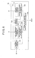
FIG. 8 is a function block diagram showing functions, among various different
functions of the ECU 26 according to this embodiment, related to monitoring and adjustment
of the tire internal air pressure. The ECU 26, in addition to the structural elements of the first
embodiment, is also provided with a transmission mode control portion 114 that is connected
to the pump/valve control amount calculation portion 108. The transmission mode control
portion 114 transmits operation information for each air adjustment electromagnetic valve 24
to each corresponding vehicle body side communication device 16, based on the detection
results of the pump/valve control amount calculation portion 108.
The vehicle body side communication device 16 then transmits the operation
information for the air adjustment electromagnetic valve 24 (which has been received from
the transmission mode control portion 114 of the ECU 26) to the corresponding wheel side
communication device 34. The wheel side communication device 34 then transmits the
operation information for the air adjustment electromagnetic valve 24 received from the
vehicle body side communication device 16 to the corresponding transmission mode
determination device 32. Then, the transmission mode determination device 32 determines
the transmission mode determination threshold value to be used based on the operation
information for the air adjustment electromagnetic valve 24 received from the wheel side
communication device 34. More particularly, when the air adjustment electromagnetic valve
24 is not operating, the first transmission mode determination threshold value is used,
whereas when the air adjustment electromagnetic valve 24 is operating the second
transmission mode determination threshold value is used.
The remaining structural elements of the third embodiment are the same as those of the
first embodiment shown in FIGS. 1 to 4.
In the third embodiment, for example, when the driver or other vehicle user of the
vehicle notifies the ECU 26 of the running environment of the vehicle 10 via the tire air
pressure indicator 21, the ECU 26 calculates the supplied air amount and the bled air amount
for the tire, and the operating mode of the air pump 20 and the adjustment amount of the air
adjustment electromagnetic valves 24. The calculated results are then transmitted to the air
pump 20 and the air adjustment electromagnetic valve 24. Next, the operation information
for the air adjustment electromagnetic valves 24 that is derived from the calculation results of
the pump/valve control amount calculation portion 108 is transmitted from the transmission
mode control portion 114 of the ECU 26 to the corresponding transmission mode
determination device 32 via the vehicle body side communication device 16 and the wheel
side communication device 34. Accordingly, when the tire internal air pressure is being pro-actively
adjusted by the air adjustment electromagnetic valve 24, the second transmission
mode determination threshold value is used by the transmission mode determination device
32. On the other hand, when the tire internal air pressure is not being pro-actively adjusted
by the air adjustment electromagnetic valve 24, the first transmission mode determination
threshold value is used by the transmission mode determination device 32.
Moreover, when the tire internal air pressure is being adjusted in order to maintain the
tire internal air pressure in the reference state based upon the detection result of the pressure
detection sensor 30, in a similar manner to described previously, the operation information of
the air adjustment electromagnetic valve 24 is transmitted from the transmission mode
control portion 114 of the ECU 26 to the wheel side communication device 34. Then, the
transmission mode determination device 32 determines whether the first transmission mode
determination threshold value or the second transmission mode determination threshold value
is to be used.
In the above described embodiment, the devices on the vehicle body 12 side and the
devices on the wheel 14 side exchange information by two-way wireless communication,
thus enabling the transmission mode determination threshold value that acts as the
determination criterion for determining the transmission mode of the wheel side
communication device 34 to be determined. Accordingly, when the air adjustment
electromagnetic valves 24 are being operated to adjust the tire internal air pressure, the
second transmission mode determination threshold value is used. As a result, it is possible to
reduce the transmission frequency at which notifications related to the occurrence of an
abnormality of the wheel 14 are transmitted, whereby it is possible to reduce the amount of
power consumed by transmissions of the wheel side communication device 34.
It should be noted that the invention is not limited to the above described exemplary
embodiments and configurations, and may be realized by appropriately replacing any of the
various elements described in the above embodiments and configurations. Further, those
skilled in the art will be able to conceive of various design changes and modifications of the
above described embodiments. Such modified and changed embodiments are also intended
to fall within the scope of the invention.
For example, in the above described embodiments, the transmission frequency of
notifications related to the occurrence of an abnormality of the tire internal air pressure from
the wheel side communication device 34 etc. is reduced by changing the transmission mode
determination threshold value that acts as the reference criterion for the transmission mode of
the wheel side communication device 34. However, other methods of achieving this
reduction can be used. For example, while the wheel state adjustment device or means
including the air adjustment electromagnetic valves 24 etc. is adjusting the tire internal air
pressure, the notification related to the occurrence of abnormalities may be stopped by
interrupting transmission by the wheel side communication device 34 of the detection result
of the pressure detection sensor 30. Accordingly, it is possible to reduce the transmission
frequency at which the wheel side communication device 34 etc. transmits notifications
related to the occurrence of abnormalities of the tire internal air pressure. Thus, with this
configuration, the transmission mode determination device 32 determines whether to
continue or interrupt the periodic information transmissions of the wheel side communication
device 34 based on the detection result of the pressure detection sensor 30, instead of by
changing the transmission mode determination threshold value. Moreover, the wheel side
communication device 34 may transmit the detection result of the pressure detection sensor
30 etc. based on information which is received from the corresponding transmission mode
determination device 32 about whether continuation or interruption of the periodic
information transmission has been determined.
Further, examples are described for the above embodiments in which, when, for
example, the tire internal air pressure is increased, the indication signal that the tire internal
air pressure is being adjusted by the air adjustment electromagnetic valve 24 etc. is realized
by the tire internal air pressure being decreased once and then increased within a
predetermined period of time. However, the invention is not limited to this configuration.
For example, the indication signal that the tire internal air pressure is being adjusted may be
realized by intermittently increasing or decreasing the tire internal air pressure. If such a
configuration is adopted, it is preferable that the air pump 20 and the air adjustment
electromagnetic valve 24 are controlled such that the tire internal air pressure exhibits
behavior that does not usually occur during normal running of the vehicle 10.
Furthermore, examples are described for the above embodiments in which the tire
internal air pressure is changed to suit the running environment when the driver or other
vehicle user gives an instruction. However, the invention is not limited in this respect, and
may be applied to, for example, a configuration in which (i) a vehicle speed sensor, a camera
or the like are used to detect the running environment of the vehicle 10, and (ii) the tire
internal air pressure is changed based on an automatic determination of the running
environment based on the obtained detection results.
In addition, an explanation is presented for the above described first and second
embodiments in which, when the second transmission mode determination threshold value is
used for determination of the transmission mode of the wheel side communication device 34,
the determination as to whether to return the transmission mode determination threshold
value to the first transmission mode determination threshold value is based upon whether a
predetermined time has elapsed since the second transmission mode determination threshold
value was set. However, the invention is not limited to this configuration. For example, the
invention may be realized such that when the adjustment of the tire internal air pressure by
the air adjustment electromagnetic valve 24 etc. is completed, an indication signal indicating
the completion of adjustment is transmitted to the transmission mode determination device
32. Accordingly, the transmission mode determination device 32 can determine whether to
return the transmission mode determination threshold value from the second transmission
mode determination threshold value to the first transmission mode determination threshold
value based on the received indication signal. The indication signal that the adjustment of the
tire internal air pressure is completed may, like the above described indication signal that tire
internal air pressure is being adjusted, be transmitted to the transmission mode determination
device 32 on the wheel 14 side from the devices on the vehicle body 12 side using the
behavior of the tire internal air pressure.
Moreover, an example is described for the above embodiments in which it is
determined whether or not an abnormality of the wheel 14 has occurred based on the absolute
value and the change amount of the tire internal air pressure. However, the invention is not
limited in this respect, and may be configured such that, for example, the differences of the
transmission modes and the transmission frequencies of the wheel side communication
device 34 are used as a basis for determining whether or not an abnormality of the wheel 14
has occurred. For example, if the information transmitted from the vehicle body side
communication device 16 includes information indicating that the transmission mode of the
wheel side communication device 34 is the normal transmission mode, or if the transmission
frequency of transmissions from the wheel side communication device 34 to the vehicle body
side communication device 16 is comparatively low, it is possible to determine that an
abnormality of the wheel 14 has not occurred. Given this fact, the warning determination
portion 110 need not activate the warning device 18. Alternatively, if the information
transmitted from the vehicle body side communication device 16 includes information
indicating that the transmission mode of the wheel side communication device 34 is the
emergency transmission mode, or if the transmission frequency of transmissions from the
wheel side communication device 34 to the vehicle body side communication device 16 is
comparatively high, it is possible to determine that an abnormality of the wheel 14 has
occurred. Accordingly, the warning determination portion 110 can activate the warning
device 18 based on this fact.