EP1585449B1 - Articular facet interference screw - Google Patents
Articular facet interference screw Download PDFInfo
- Publication number
- EP1585449B1 EP1585449B1 EP02774232A EP02774232A EP1585449B1 EP 1585449 B1 EP1585449 B1 EP 1585449B1 EP 02774232 A EP02774232 A EP 02774232A EP 02774232 A EP02774232 A EP 02774232A EP 1585449 B1 EP1585449 B1 EP 1585449B1
- Authority
- EP
- European Patent Office
- Prior art keywords
- bone screw
- screw
- screw head
- bone
- central axis
- Prior art date
- Legal status (The legal status is an assumption and is not a legal conclusion. Google has not performed a legal analysis and makes no representation as to the accuracy of the status listed.)
- Expired - Lifetime
Links
- 210000000988 bone and bone Anatomy 0.000 claims description 55
- 238000003780 insertion Methods 0.000 claims description 14
- 230000037431 insertion Effects 0.000 claims description 14
- 238000000034 method Methods 0.000 claims description 11
- 238000010079 rubber tapping Methods 0.000 claims description 3
- 238000005553 drilling Methods 0.000 claims description 2
- 239000007943 implant Substances 0.000 description 4
- 238000013459 approach Methods 0.000 description 2
- 239000000463 material Substances 0.000 description 2
- 238000013508 migration Methods 0.000 description 2
- 230000005012 migration Effects 0.000 description 2
- 229920002430 Fibre-reinforced plastic Polymers 0.000 description 1
- 229910001069 Ti alloy Inorganic materials 0.000 description 1
- RTAQQCXQSZGOHL-UHFFFAOYSA-N Titanium Chemical compound [Ti] RTAQQCXQSZGOHL-UHFFFAOYSA-N 0.000 description 1
- 238000010420 art technique Methods 0.000 description 1
- 208000037873 arthrodesis Diseases 0.000 description 1
- 238000005452 bending Methods 0.000 description 1
- 230000002146 bilateral effect Effects 0.000 description 1
- 239000000919 ceramic Substances 0.000 description 1
- 238000013461 design Methods 0.000 description 1
- 239000011151 fibre-reinforced plastic Substances 0.000 description 1
- 230000004927 fusion Effects 0.000 description 1
- 230000004807 localization Effects 0.000 description 1
- 230000001045 lordotic effect Effects 0.000 description 1
- 210000003205 muscle Anatomy 0.000 description 1
- 125000006850 spacer group Chemical group 0.000 description 1
- 238000001356 surgical procedure Methods 0.000 description 1
- 229910052719 titanium Inorganic materials 0.000 description 1
- 239000010936 titanium Substances 0.000 description 1
Images


Classifications
-
- A—HUMAN NECESSITIES
- A61—MEDICAL OR VETERINARY SCIENCE; HYGIENE
- A61B—DIAGNOSIS; SURGERY; IDENTIFICATION
- A61B17/00—Surgical instruments, devices or methods, e.g. tourniquets
- A61B17/56—Surgical instruments or methods for treatment of bones or joints; Devices specially adapted therefor
- A61B17/58—Surgical instruments or methods for treatment of bones or joints; Devices specially adapted therefor for osteosynthesis, e.g. bone plates, screws, setting implements or the like
- A61B17/88—Osteosynthesis instruments; Methods or means for implanting or extracting internal or external fixation devices
-
- A—HUMAN NECESSITIES
- A61—MEDICAL OR VETERINARY SCIENCE; HYGIENE
- A61B—DIAGNOSIS; SURGERY; IDENTIFICATION
- A61B17/00—Surgical instruments, devices or methods, e.g. tourniquets
- A61B17/56—Surgical instruments or methods for treatment of bones or joints; Devices specially adapted therefor
- A61B17/58—Surgical instruments or methods for treatment of bones or joints; Devices specially adapted therefor for osteosynthesis, e.g. bone plates, screws, setting implements or the like
- A61B17/68—Internal fixation devices, including fasteners and spinal fixators, even if a part thereof projects from the skin
- A61B17/70—Spinal positioners or stabilisers ; Bone stabilisers comprising fluid filler in an implant
- A61B17/7062—Devices acting on, attached to, or simulating the effect of, vertebral processes, vertebral facets or ribs ; Tools for such devices
- A61B17/7064—Devices acting on, attached to, or simulating the effect of, vertebral facets; Tools therefor
-
- A—HUMAN NECESSITIES
- A61—MEDICAL OR VETERINARY SCIENCE; HYGIENE
- A61B—DIAGNOSIS; SURGERY; IDENTIFICATION
- A61B17/00—Surgical instruments, devices or methods, e.g. tourniquets
- A61B17/56—Surgical instruments or methods for treatment of bones or joints; Devices specially adapted therefor
- A61B17/58—Surgical instruments or methods for treatment of bones or joints; Devices specially adapted therefor for osteosynthesis, e.g. bone plates, screws, setting implements or the like
- A61B17/68—Internal fixation devices, including fasteners and spinal fixators, even if a part thereof projects from the skin
- A61B17/84—Fasteners therefor or fasteners being internal fixation devices
- A61B17/86—Pins or screws or threaded wires; nuts therefor
- A61B17/8605—Heads, i.e. proximal ends projecting from bone
- A61B17/861—Heads, i.e. proximal ends projecting from bone specially shaped for gripping driver
- A61B17/8615—Heads, i.e. proximal ends projecting from bone specially shaped for gripping driver at the central region of the screw head
-
- A—HUMAN NECESSITIES
- A61—MEDICAL OR VETERINARY SCIENCE; HYGIENE
- A61B—DIAGNOSIS; SURGERY; IDENTIFICATION
- A61B17/00—Surgical instruments, devices or methods, e.g. tourniquets
- A61B17/56—Surgical instruments or methods for treatment of bones or joints; Devices specially adapted therefor
- A61B17/58—Surgical instruments or methods for treatment of bones or joints; Devices specially adapted therefor for osteosynthesis, e.g. bone plates, screws, setting implements or the like
- A61B17/68—Internal fixation devices, including fasteners and spinal fixators, even if a part thereof projects from the skin
- A61B17/84—Fasteners therefor or fasteners being internal fixation devices
- A61B17/86—Pins or screws or threaded wires; nuts therefor
- A61B17/8625—Shanks, i.e. parts contacting bone tissue
-
- A—HUMAN NECESSITIES
- A61—MEDICAL OR VETERINARY SCIENCE; HYGIENE
- A61B—DIAGNOSIS; SURGERY; IDENTIFICATION
- A61B17/00—Surgical instruments, devices or methods, e.g. tourniquets
- A61B17/56—Surgical instruments or methods for treatment of bones or joints; Devices specially adapted therefor
- A61B17/58—Surgical instruments or methods for treatment of bones or joints; Devices specially adapted therefor for osteosynthesis, e.g. bone plates, screws, setting implements or the like
- A61B17/68—Internal fixation devices, including fasteners and spinal fixators, even if a part thereof projects from the skin
- A61B17/685—Elements to be fitted on the end of screws or wires, e.g. protective caps
-
- A—HUMAN NECESSITIES
- A61—MEDICAL OR VETERINARY SCIENCE; HYGIENE
- A61B—DIAGNOSIS; SURGERY; IDENTIFICATION
- A61B17/00—Surgical instruments, devices or methods, e.g. tourniquets
- A61B17/56—Surgical instruments or methods for treatment of bones or joints; Devices specially adapted therefor
- A61B17/58—Surgical instruments or methods for treatment of bones or joints; Devices specially adapted therefor for osteosynthesis, e.g. bone plates, screws, setting implements or the like
- A61B17/68—Internal fixation devices, including fasteners and spinal fixators, even if a part thereof projects from the skin
- A61B17/84—Fasteners therefor or fasteners being internal fixation devices
- A61B17/86—Pins or screws or threaded wires; nuts therefor
- A61B17/8625—Shanks, i.e. parts contacting bone tissue
- A61B17/8635—Tips of screws
-
- A—HUMAN NECESSITIES
- A61—MEDICAL OR VETERINARY SCIENCE; HYGIENE
- A61B—DIAGNOSIS; SURGERY; IDENTIFICATION
- A61B17/00—Surgical instruments, devices or methods, e.g. tourniquets
- A61B17/56—Surgical instruments or methods for treatment of bones or joints; Devices specially adapted therefor
- A61B17/58—Surgical instruments or methods for treatment of bones or joints; Devices specially adapted therefor for osteosynthesis, e.g. bone plates, screws, setting implements or the like
- A61B17/68—Internal fixation devices, including fasteners and spinal fixators, even if a part thereof projects from the skin
- A61B17/84—Fasteners therefor or fasteners being internal fixation devices
- A61B17/86—Pins or screws or threaded wires; nuts therefor
- A61B17/864—Pins or screws or threaded wires; nuts therefor hollow, e.g. with socket or cannulated
-
- A—HUMAN NECESSITIES
- A61—MEDICAL OR VETERINARY SCIENCE; HYGIENE
- A61B—DIAGNOSIS; SURGERY; IDENTIFICATION
- A61B17/00—Surgical instruments, devices or methods, e.g. tourniquets
- A61B17/56—Surgical instruments or methods for treatment of bones or joints; Devices specially adapted therefor
- A61B17/58—Surgical instruments or methods for treatment of bones or joints; Devices specially adapted therefor for osteosynthesis, e.g. bone plates, screws, setting implements or the like
- A61B17/88—Osteosynthesis instruments; Methods or means for implanting or extracting internal or external fixation devices
- A61B17/8875—Screwdrivers, spanners or wrenches
-
- A—HUMAN NECESSITIES
- A61—MEDICAL OR VETERINARY SCIENCE; HYGIENE
- A61B—DIAGNOSIS; SURGERY; IDENTIFICATION
- A61B17/00—Surgical instruments, devices or methods, e.g. tourniquets
- A61B17/56—Surgical instruments or methods for treatment of bones or joints; Devices specially adapted therefor
- A61B17/58—Surgical instruments or methods for treatment of bones or joints; Devices specially adapted therefor for osteosynthesis, e.g. bone plates, screws, setting implements or the like
- A61B17/68—Internal fixation devices, including fasteners and spinal fixators, even if a part thereof projects from the skin
- A61B17/84—Fasteners therefor or fasteners being internal fixation devices
- A61B17/86—Pins or screws or threaded wires; nuts therefor
- A61B2017/8655—Pins or screws or threaded wires; nuts therefor with special features for locking in the bone
Definitions
- This invention concerns a bone screw, in particular for locking an articular facet between the superior and inferior articular processes of two vertebral bodies, in accordance with the pre-characterising portion of Claim 1.
- the anterior and the posterior columns must be treated.
- the goal of the treatment is the restoration of the lordotic curve and the anatomically correct disc space.
- the posterior vertebral column, where the articular facet is located, should be locked as well.
- State-of-the-art techniques consider translaminar screws or transpedical instrumentation which, however, are not satisfactory.
- the invention as claimed aims at solving the above described problems.
- the present invention provides a bone screw as defined in Claim 1.
- the interference screw according to the invention allows a new surgical technique to lock the articular facets of vertebral bodies.
- the natural functional spine unit contains two articular facets.
- the function of the screw according to the invention is the interference in the sense of obstruction or fixation of said articular facets. Since the core diameter of the screw is significantly larger than the gap in the articular facet, the device is hindering the natural articulation.
- the function of the screw thread is the insertion by rotation. After insertion the screw thread protects the screw from axial migration and the anti-rotation device protects the screw from migration by rotation.
- the locking screws are inserted through two percutaneous approaches in the trajectories parallel to the articular surface of the articular facet.
- Aiming wires guarantee the correct positioning.
- An anti-rotation element keeps the bone screw in position and hinders the screws from turning out if micro-motion is applied to the screws.
- This technique is applicable if the anterior vertebral column (i.e. the intervertebral space of the related segment) is stabilised with a spacer such as an intervertebral cage.
- the grooves on the periphery of the screw head are running essentially parallel to the central axis.
- Such an angulation in a radial plane and measured relative to the central axis might be in the order of up to 60°, but preferably less than 20°.
- the possible angulation in a tangential plane and measured relative to the central axis might be in the order of maximum 20 °, preferably less than 10°.
- the bone screw is provided with at least one pair of diametrally opposed grooves on the periphery of said screw head which enhances stability of the implant.
- the screw head may be provided with a central cavity coaxially arranged with respect to said central axis, e.g. with a polygonal profile, preferably a hexagonal profile for receiving a screw-driver having a corresponding profile.
- the grooves on the periphery of the screw head may be juxtaposed to the polygonal planes of said central cavity.
- an anti-rotation element is insertable in said groove or said pair of grooves on the periphery of said screw head, whereby said anti-rotation element in its inserted position projects radially out of the periphery of said screw head.
- the anti-rotation element is a U-shaped staple with two legs and a central portion bridging said two legs and designed for insertion into said groove or said pair of grooves of said screw head.
- the anti-rotation element has preferably a diameter which is larger than said screw head.
- the anti-rotation element in form of a U-shaped staple may be provided with a guiding element attached to said central portion and running essentially parallel to said legs.
- the guiding element may be in the form of a plate, a circular cylinder or a prism designed for insertion into said central cavity of said screw head.
- the cylindrical shape of the guiding element has the advantage of a more accurate gliding.
- the central portion of the anti-rotation element may be provided with at least one perforation for removal of the screw.
- the threaded shaft of the bone screw has preferably a thread with a high angle of pressure, e.g. in the range of 4° to 70°.
- the flank of said thread can be symmetrically or asymmetrically oriented.
- the asymmetrically oriented thread is compressing particularly cancellous bone. This increases initial fixation stability.
- the bone screw may be self-tapping, preferably by means of a cutting edge.
- the core of the screw shaft may be either cylindrical or tapering away from the screw head.
- the shaft In the case of a conical shape of the core the shaft is compressing the surrounding bone. This increases the initial stability of the implant.
- the envelope of the threaded shaft may be cylindrical allowing also a constant insertion torque.
- the envelope of the threaded shaft preferably tapers away from the screw head so that the purchase of the thread in the bone is increasing by turning the screw in.
- the bone screw may be self-drilling, preferably by means of a chucking groove.
- the new method for locking an articular facet between the superior and inferior articular processes of two vertebral bodies consists in the insertion of the threaded shaft of a bone screw in the gap of said articular facet.
- the bone screw is preferably cannulated and insertion is performed by means of an aiming wire.
- the bone screw has preferably a screw head with a larger diameter than said threaded shaft and said threaded shaft is inserted in said gap of said articular facet until said screw head touches the bone.
- an anti-rotation element may be applied to said screw head such that rotation of said bone screw is prevented.
- the bone screw 1 as represented in Figs. 1, 2a and 2b is used in particular for locking an articular facet between the superior and inferior articular processes of two vertebral bodies. It has a threaded shaft 2, a screw head 3 and a central axis 4.
- the screw head 3 is provided with six grooves 5 regularly disposed on the periphery of the screw head 3 running essentially parallel to the central axis 4.
- the screw head 3 is further provided with a central cavity 6 coaxially arranged with respect to the central axis 4 and having a hexagonal shape.
- the anti-rotation element 10 is provided with a U-shaped staple having two legs 11 and a central portion 13 bridging said two legs 11.
- the U-shaped staple is provided with a guiding element 12 - having the shape of a circular cylinder - attached to the central portion 13 and running essentially parallel to the legs 11.
- the anti-rotation element 10 may be connected to the bone screw 1 by moving it along the central axis 4 whereby its central portion 13 enters the central cavity 6 of the screw head 3 and the two legs 11 are inserted into one of the three pairs of grooves 5 of the screw head 3 as shown in Fig. 2b.
- the free ends of the two legs 11 are provided with an protrusion 15 oriented radially inwards to the central axis 4 so that when the legs 11 are gliding along the grooves 5 the protrusions 15 will click under the lower edge 16 of the screw head 3 thereby securing the anti-rotation element 10 against withdrawal in the opposite axial direction.
- the central portion 13 of the U-shaped staple is further provided with at a perforation 14 facilitating removal of the bone screw 1.
- Useful materials for the bone screw 1 as well as for the anti-rotation element 10 are titanium, titanium alloys or fibre-reinforced plastic materials. They may be coated with ceramic.
- the method of operation as described can be performed on one side of the vertebral column only but is preferably performed simultaneously on the right and left side, as shown in Figs. 3 to 7, which has biomechanical advantages.
Description
- This invention concerns a bone screw, in particular for locking an articular facet between the superior and inferior articular processes of two vertebral bodies, in accordance with the pre-characterising portion of
Claim 1. - To achieve a circumferential arthrodesis (fusion) the anterior and the posterior columns must be treated. The goal of the treatment is the restoration of the lordotic curve and the anatomically correct disc space. Anteriorly, i.e. in the intervertebral space, implants like cages are inserted after disc removal. The posterior vertebral column, where the articular facet is located, should be locked as well. State-of-the-art techniques consider translaminar screws or transpedical instrumentation which, however, are not satisfactory.
- Translaminar screws have certain disadvantages, like
- a) the screw insertion point is difficult to localize; the localization is done under full view, i.e. a separate posterior incision is performed medially whereas muscles must be separated from spinal and laminar processes. Most morbidity results from medial incision;
- b) the surgeon's view is two-dimensional due to the small incision which may result in interference of the second screw with the first one; and
- c) aiming devices or navigation tools did not improve insertion technique or precision of screw placement.
- From US-A 2001/007074 A1 STROBEL a bone screw is known according the preamble of
claim 1. - From US 4,754,749 TSOU another bone screw is known which has two closed canals in the screw head at an angle with the screw axis. A guide pin is insertable in one of these closed canals, so that upon insertion of the guide pin it projects radially over the shaft and axially over the head of the screw which renders it complicated and rather unstable.
- The invention as claimed aims at solving the above described problems.
- The present invention provides a bone screw as defined in
Claim 1. - The advantages obtained with the use of said bone screw are the following:
- percutaneous approach which results in reduced morbidity;
- low implant cost due to simple design, in particular in comparison to transpedicular fixation;
- lower risk with regard to screw positioning compared to translaminar screws; and
- easy removal of the screws.
- The interference screw according to the invention allows a new surgical technique to lock the articular facets of vertebral bodies.
- The natural functional spine unit (FSU) contains two articular facets. The function of the screw according to the invention is the interference in the sense of obstruction or fixation of said articular facets. Since the core diameter of the screw is significantly larger than the gap in the articular facet, the device is hindering the natural articulation. The function of the screw thread is the insertion by rotation. After insertion the screw thread protects the screw from axial migration and the anti-rotation device protects the screw from migration by rotation.
- According to a method of using the invention the locking screws are inserted through two percutaneous approaches in the trajectories parallel to the articular surface of the articular facet. Aiming wires guarantee the correct positioning. An anti-rotation element keeps the bone screw in position and hinders the screws from turning out if micro-motion is applied to the screws. This technique is applicable if the anterior vertebral column (i.e. the intervertebral space of the related segment) is stabilised with a spacer such as an intervertebral cage.
- According to a special embodiment the grooves on the periphery of the screw head are running essentially parallel to the central axis. This shall be interpreted in such a way that minor angulation with regard to the central axis either towards radially the latter or tangentially to it would still be functional. Such an angulation in a radial plane and measured relative to the central axis might be in the order of up to 60°, but preferably less than 20°. The possible angulation in a tangential plane and measured relative to the central axis might be in the order of maximum 20 °, preferably less than 10°.
- In a particular embodiment the bone screw is provided with at least one pair of diametrally opposed grooves on the periphery of said screw head which enhances stability of the implant.
- The screw head may be provided with a central cavity coaxially arranged with respect to said central axis, e.g. with a polygonal profile, preferably a hexagonal profile for receiving a screw-driver having a corresponding profile.
The grooves on the periphery of the screw head may be juxtaposed to the polygonal planes of said central cavity. By this measure a higher mechanical strength can be achieved. - In a further embodiment an anti-rotation element is insertable in said groove or said pair of grooves on the periphery of said screw head, whereby said anti-rotation element in its inserted position projects radially out of the periphery of said screw head. The anti-rotation element is a U-shaped staple with two legs and a central portion bridging said two legs and designed for insertion into said groove or said pair of grooves of said screw head. The anti-rotation element has preferably a diameter which is larger than said screw head. The anti-rotation element in form of a U-shaped staple may be provided with a guiding element attached to said central portion and running essentially parallel to said legs. The guiding element may be in the form of a plate, a circular cylinder or a prism designed for insertion into said central cavity of said screw head. The cylindrical shape of the guiding element has the advantage of a more accurate gliding.
- The central portion of the anti-rotation element may be provided with at least one perforation for removal of the screw.
- The threaded shaft of the bone screw has preferably a thread with a high angle of pressure, e.g. in the range of 4° to 70°. The flank of said thread can be symmetrically or asymmetrically oriented. The asymmetrically oriented thread is compressing particularly cancellous bone. This increases initial fixation stability.
- The bone screw may be self-tapping, preferably by means of a cutting edge.
- The core of the screw shaft may be either cylindrical or tapering away from the screw head.
- In the case of cylindrical core of the screw shaft various advantages can be achieved, namely:
- a continuous bending strength along the screw shaft;
- the application of a constant insertion torque while turning the screw in the articular facet; and
- due to the constant shaft diameter the screw does not become loose if the device is turned back slightly after insertion.
- In the case of a conical shape of the core the shaft is compressing the surrounding bone. This increases the initial stability of the implant.
- The envelope of the threaded shaft may be cylindrical allowing also a constant insertion torque. However, the envelope of the threaded shaft preferably tapers away from the screw head so that the purchase of the thread in the bone is increasing by turning the screw in.
- The bone screw may be self-drilling, preferably by means of a chucking groove.
- The new method for locking an articular facet between the superior and inferior articular processes of two vertebral bodies consists in the insertion of the threaded shaft of a bone screw in the gap of said articular facet. To that purpose the bone screw is preferably cannulated and insertion is performed by means of an aiming wire. The bone screw has preferably a screw head with a larger diameter than said threaded shaft and said threaded shaft is inserted in said gap of said articular facet until said screw head touches the bone. Upon insertion of said bone screw an anti-rotation element may be applied to said screw head such that rotation of said bone screw is prevented.
- The various features of novelty which characterize the invention are pointed out with particularity in the claims annexed to and forming part of this disclosure. For the better understanding of the invention, its operating advantages and specific objects attained by its use, reference should be had to the accompanying drawings, examples and descriptive matter in which are illustrated and described preferred embodiments of the invention.
- In the drawings:
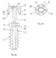
- Fig. 1 is a perspective view of the bone screw according to the invention together with an anti-rotation element to be used with the screw;
- Fig. 2a is a longitudinal section through the central axis of the screw and the anti-rotation element according to Fig. 1;
- Fig. 2b is a top view of the bone screw according to Fig. 1 with the anti-rotation element inserted into the screw head;
- Fig. 3 is a perspective view of a trocar for bringing an aiming wire into the gap between the articular facet;
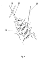
- Fig. 4. is a perspective view of a drill bit, the aiming wires being temporarily fixed in the gaps of the articular facets;
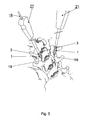
- Fig. 5 is a perspective view of the bone screw being inserted by means of a screw-driver into the gap of the articular facet by using the temporarily fixed guiding wire;
- Fig. 6 is a perspective view of the anti-rotation element being put over the screw head into its grooves closest to the joint gap; and
- Fig. 7 is a perspective view of the inserted bone screw to which the anti-rotation element has been attached.
- The
bone screw 1 as represented in Figs. 1, 2a and 2b is used in particular for locking an articular facet between the superior and inferior articular processes of two vertebral bodies. It has a threadedshaft 2, ascrew head 3 and acentral axis 4. Thescrew head 3 is provided with sixgrooves 5 regularly disposed on the periphery of thescrew head 3 running essentially parallel to thecentral axis 4. Thescrew head 3 is further provided with acentral cavity 6 coaxially arranged with respect to thecentral axis 4 and having a hexagonal shape. - The
anti-rotation element 10 is provided with a U-shaped staple having twolegs 11 and acentral portion 13 bridging said twolegs 11. The U-shaped staple is provided with a guiding element 12 - having the shape of a circular cylinder - attached to thecentral portion 13 and running essentially parallel to thelegs 11. As can be seen in Figs. 1 and 2a theanti-rotation element 10 may be connected to thebone screw 1 by moving it along thecentral axis 4 whereby itscentral portion 13 enters thecentral cavity 6 of thescrew head 3 and the twolegs 11 are inserted into one of the three pairs ofgrooves 5 of thescrew head 3 as shown in Fig. 2b.
The free ends of the twolegs 11 are provided with anprotrusion 15 oriented radially inwards to thecentral axis 4 so that when thelegs 11 are gliding along thegrooves 5 theprotrusions 15 will click under thelower edge 16 of thescrew head 3 thereby securing theanti-rotation element 10 against withdrawal in the opposite axial direction.
Thecentral portion 13 of the U-shaped staple is further provided with at aperforation 14 facilitating removal of thebone screw 1. - Useful materials for the
bone screw 1 as well as for theanti-rotation element 10 are titanium, titanium alloys or fibre-reinforced plastic materials. They may be coated with ceramic. - A detailed method of operation follows for the better understanding of the invention:
- 1. Both positions in extension of the articulating planes of the articular facet concerned are identified and marked accordingly on the skin. To this purpose an image intensifier is used to control position and direction.
- 2. Bilateral skin incisions are performed in the direction of the articular facets.
- 3. Depending on the surgeon's preference, a
trocar 17 or similar instrument is used to bring an aimingwire 18 into thegap 19 between the articular facets (Fig. 3). Positional control is indicated using an image intensifier. - 4. As shown in Fig. 4 the aiming
wires 18 are temporarily fixed in thegaps 19 of the articular facets by means of the drill bit 20 ("screw head reamer" or "counter sink"). - 5. As shown in Fig. 5 a cannulated and self-tapping
bone screw 1 is inserted by means of a screw-driver 21 into thegap 19 by using the temporarily fixed guidingwires 18 until the screw heads 3 of the bone screws 1 are touching the bone. - 6. As shown in Fig. 6 an
anti-rotations element 10 is put over thescrew head 3 in the grooves 5 (notches) closest to thejoint gap 19. Eventually thebone screw 1 must be turned back by some degrees in order to match the grooves 5 (notches) in thescrew head 3 with the joint gap 19 (Fig. 7). - 7. All instruments are removed.
- 8. The placement of the bone screws 1 is verified by using an image identifier and the wound is closed.
- The method of operation as described can be performed on one side of the vertebral column only but is preferably performed simultaneously on the right and left side, as shown in Figs. 3 to 7, which has biomechanical advantages.
Claims (22)
- Bone screw (1), in particular for locking an articular facet between the superior and inferior articular processes of two vertebral bodies, having a threaded shaft (2), a screw head (3) and a central axis (4), whereby said screw head (3) is provided with at least one axial groove (5) on its periphery,
characterized in that
said bone screw (1) is provided with an anti-rotation element (10) in the form of a U-shaped staple with two legs (11) and a central portion (13) bridging said two legs (11) and being insertable in said at least one groove (5), whereby said anti-rotation element (10) in its inserted position projects radially out of the periphery of said screw head (3). - Bone screw (1) according to claim 1, characterized in that the at least one axial groove (5) is running essentially parallel to said central axis (4).
- Bone screw (1) according to claim 1, characterized in that the at least one axial groove (5) has an angulation in a radial plane and measured relatively to said the central axis (4) in the order of less than 60° and preferably less than 20°.
- Bone screw (1) according to claim 1, characterized in that the at least one axial groove (5) has an angulation in a tangential plane and measured relatively to said central axis (4) in the order of less than 20°.
- Bone screw (1) according to claim 4, characterized in that the at least one axial groove (5) has an angulation in a tangential plane and measured relatively to said central axis (4) in the order of less than 10°.
- Bone screw (1) according to one of the claims 1 - 5, characterized in that is provided with at least one pair of diametrally opposed grooves (5) on the periphery of said screw head (3).
- Bone screw (1) according to one of the claims 1 - 6, characterized in that said screw head (3) is provided with a central cavity (6) coaxially arranged with respect to said central axis (4).
- Bone screw (1) according to one of the claims 1 to 7, characterized in that it is self-drilling, preferably by means of a chucking groove.
- Bone screw (1) according to one of the claims 1 - 8, characterized in that said anti-rotation element (10) has a diameter which is larger than said screw head (3).
- Bone screw (1) according to one of the claims 1 - 9, characterized in that said U-shaped staple is provided with a guiding element (12) attached to said central portion (13) and running essentially parallel to said legs (11).
- Bone screw (1) according to claim 10, characterized in that said guiding element (12) is in the form of a plate, a circular cylinder or a prism designed for insertion into said central cavity (6) of said screw head (3).
- Bone screw (1) according to one of the claims 8 to 11, characterized in that said central portion (13) is provided with at least one perforation (14).
- Bone screw (1) according to one of the claims 1 to 12, characterized in that said threaded shaft (2) has a thread (7) with a high angle of pressure, preferably in the range of 4° to 70°.
- Bone screw (1) according to claim 13, characterized in that the flank of said thread (7) is symmetrically oriented.
- Bone screw (1) according to claim 13, characterized in that the flank of said thread (7) is asymmetrically oriented.
- Bone screw (1) according to one of the claims 1 to 15, characterized in that it is self-tapping, preferably by means of a cutting edge.
- Bone screw (1) according to one of the claims 6 to 16, characterized in that said central cavity (6) has a polygonal profile, preferably a hexagonal profile.
- Bone screw (1) according to claim 17, characterized in that said grooves (5) on the periphery of said screw head (3) are juxtaposed to the polygonal planes of said central cavity (6).
- Bone screw (1) according to one of the claims 1 to 18, characterized in that the core of said shaft (2) is cylindrical.
- Bone screw (1) according to one of the claims 1 to 18, characterized in that the core of said shaft (2) tapering away from said screw head (3).
- Bone screw (1) according to one of the claims 1 to 20, characterized in that the envelope of said threaded shaft (2) is cylindrical.
- Bone screw (1) according to one of the claims 1 to 20, characterized in that the envelope of said threaded shaft (2) tapers away from said screw head (3).
Priority Applications (1)
| Application Number | Priority Date | Filing Date | Title |
|---|---|---|---|
| AT02774232T ATE339924T1 (en) | 2002-11-13 | 2002-11-13 | JOINT EXTENSION INTERFERENCE SCREW |
Applications Claiming Priority (1)
| Application Number | Priority Date | Filing Date | Title |
|---|---|---|---|
| PCT/CH2002/000608 WO2004043278A1 (en) | 2002-11-13 | 2002-11-13 | Articular facet interference screw |
Publications (3)
| Publication Number | Publication Date |
|---|---|
| EP1585449A1 EP1585449A1 (en) | 2005-10-19 |
| EP1585449B1 true EP1585449B1 (en) | 2006-09-20 |
| EP1585449B8 EP1585449B8 (en) | 2007-04-18 |
Family
ID=32304024
Family Applications (1)
| Application Number | Title | Priority Date | Filing Date |
|---|---|---|---|
| EP02774232A Expired - Lifetime EP1585449B8 (en) | 2002-11-13 | 2002-11-13 | Articular facet interference screw |
Country Status (11)
| Country | Link |
|---|---|
| US (3) | US7699878B2 (en) |
| EP (1) | EP1585449B8 (en) |
| JP (1) | JP4307387B2 (en) |
| AU (1) | AU2002340694B2 (en) |
| BR (1) | BR0215923B1 (en) |
| CA (1) | CA2505850C (en) |
| DE (1) | DE60214908T2 (en) |
| ES (1) | ES2274099T3 (en) |
| MY (1) | MY134584A (en) |
| TW (1) | TWI296194B (en) |
| WO (1) | WO2004043278A1 (en) |
Families Citing this family (115)
| Publication number | Priority date | Publication date | Assignee | Title |
|---|---|---|---|---|
| US20020169507A1 (en) | 2000-12-14 | 2002-11-14 | David Malone | Interbody spine fusion cage |
| US7157103B2 (en) | 2001-08-06 | 2007-01-02 | Euro-Celtique S.A. | Pharmaceutical formulation containing irritant |
| US6793678B2 (en) | 2002-06-27 | 2004-09-21 | Depuy Acromed, Inc. | Prosthetic intervertebral motion disc having dampening |
| AU2003261286B2 (en) | 2002-07-19 | 2009-10-29 | Interventional Spine, Inc. | Method and apparatus for spinal fixation |
| CA2505850C (en) * | 2002-11-13 | 2011-01-04 | Synthes (U.S.A.) | Articular facet interference screw |
| US7862586B2 (en) | 2003-11-25 | 2011-01-04 | Life Spine, Inc. | Spinal stabilization systems |
| US7201920B2 (en) | 2003-11-26 | 2007-04-10 | Acura Pharmaceuticals, Inc. | Methods and compositions for deterring abuse of opioid containing dosage forms |
| US8900270B2 (en) * | 2004-02-17 | 2014-12-02 | Gmedelaware 2 Llc | Facet joint replacement instruments and methods |
| US7452369B2 (en) * | 2004-10-18 | 2008-11-18 | Barry Richard J | Spine microsurgery techniques, training aids and implants |
| US8075591B2 (en) | 2004-11-09 | 2011-12-13 | Depuy Spine, Inc. | Minimally invasive spinal fixation guide systems and methods |
| US7837713B2 (en) * | 2004-11-22 | 2010-11-23 | Minsurg International, Inc. | Methods and surgical kits for minimally-invasive facet joint fusion |
| US8021392B2 (en) * | 2004-11-22 | 2011-09-20 | Minsurg International, Inc. | Methods and surgical kits for minimally-invasive facet joint fusion |
| US20060111779A1 (en) * | 2004-11-22 | 2006-05-25 | Orthopedic Development Corporation, A Florida Corporation | Minimally invasive facet joint fusion |
| US8696707B2 (en) | 2005-03-08 | 2014-04-15 | Zyga Technology, Inc. | Facet joint stabilization |
| US7481811B2 (en) * | 2005-03-11 | 2009-01-27 | Synthes (U.S.A.) | Translational plate with spring beam retainer |
| EP1983938A4 (en) * | 2006-02-02 | 2012-07-25 | Trinity Orthopedics | Percutaneous facet joint fusion system and method |
| EP1996103A2 (en) * | 2006-03-06 | 2008-12-03 | Sonja Deola | Bone implant screw with increased bone-implant interface |
| US20080027444A1 (en) * | 2006-07-28 | 2008-01-31 | Malek Michel H | Bone anchor device |
| US8105382B2 (en) | 2006-12-07 | 2012-01-31 | Interventional Spine, Inc. | Intervertebral implant |
| US20080161929A1 (en) | 2006-12-29 | 2008-07-03 | Mccormack Bruce | Cervical distraction device |
| US8133261B2 (en) * | 2007-02-26 | 2012-03-13 | Depuy Spine, Inc. | Intra-facet fixation device and method of use |
| US8894685B2 (en) | 2007-04-13 | 2014-11-25 | DePuy Synthes Products, LLC | Facet fixation and fusion screw and washer assembly and method of use |
| US7901439B2 (en) * | 2007-04-13 | 2011-03-08 | Horton Kenneth L | Allograft spinal facet fusion system |
| US8197513B2 (en) | 2007-04-13 | 2012-06-12 | Depuy Spine, Inc. | Facet fixation and fusion wedge and method of use |
| US8043334B2 (en) | 2007-04-13 | 2011-10-25 | Depuy Spine, Inc. | Articulating facet fusion screw |
| US20080276159A1 (en) * | 2007-05-01 | 2008-11-06 | International Business Machines Corporation | Creating Annotated Recordings and Transcripts of Presentations Using a Mobile Device |
| EP2155124A4 (en) | 2007-05-22 | 2013-04-03 | Vg Innovations Llc | Method and apparatus for spinal facet fusion |
| US7998176B2 (en) * | 2007-06-08 | 2011-08-16 | Interventional Spine, Inc. | Method and apparatus for spinal stabilization |
| US8900307B2 (en) | 2007-06-26 | 2014-12-02 | DePuy Synthes Products, LLC | Highly lordosed fusion cage |
| US8343189B2 (en) * | 2007-09-25 | 2013-01-01 | Zyga Technology, Inc. | Method and apparatus for facet joint stabilization |
| US9005288B2 (en) | 2008-01-09 | 2015-04-14 | Providence Medical Techonlogy, Inc. | Methods and apparatus for accessing and treating the facet joint |
| EP2471493A1 (en) | 2008-01-17 | 2012-07-04 | Synthes GmbH | An expandable intervertebral implant and associated method of manufacturing the same |
| EP2249730A1 (en) | 2008-03-06 | 2010-11-17 | Synthes GmbH | Facet interference screw |
| BRPI0910325A8 (en) | 2008-04-05 | 2019-01-29 | Synthes Gmbh | expandable intervertebral implant |
| EP2206470A3 (en) * | 2008-05-21 | 2011-01-12 | Hubert L. Gooch | Systems for the medical treatment of structural tissue |
| US9381049B2 (en) | 2008-06-06 | 2016-07-05 | Providence Medical Technology, Inc. | Composite spinal facet implant with textured surfaces |
| EP2361046B1 (en) * | 2008-06-06 | 2019-04-24 | Providence Medical Technology, Inc. | Cervical distraction/implant delivery device |
| CA2725811A1 (en) | 2008-06-06 | 2009-12-10 | Providence Medical Technology, Inc. | Facet joint implants and delivery tools |
| US9333086B2 (en) | 2008-06-06 | 2016-05-10 | Providence Medical Technology, Inc. | Spinal facet cage implant |
| US8267966B2 (en) * | 2008-06-06 | 2012-09-18 | Providence Medical Technology, Inc. | Facet joint implants and delivery tools |
| US8361152B2 (en) | 2008-06-06 | 2013-01-29 | Providence Medical Technology, Inc. | Facet joint implants and delivery tools |
| US11224521B2 (en) | 2008-06-06 | 2022-01-18 | Providence Medical Technology, Inc. | Cervical distraction/implant delivery device |
| US8715321B2 (en) * | 2008-10-01 | 2014-05-06 | Life Spine, Inc. | Spinal facet fastener |
| ES2553591T3 (en) | 2008-10-21 | 2015-12-10 | Spinewelding Ag | Fusion device and set of tools for the fusion of a human or animal joint |
| US8187304B2 (en) * | 2008-11-10 | 2012-05-29 | Malek Michel H | Facet fusion system |
| US8617225B2 (en) | 2008-12-24 | 2013-12-31 | DePuy Synthes Products, LLC | Spline drive for threaded post-type bone anchors |
| US9526620B2 (en) | 2009-03-30 | 2016-12-27 | DePuy Synthes Products, Inc. | Zero profile spinal fusion cage |
| US8394125B2 (en) | 2009-07-24 | 2013-03-12 | Zyga Technology, Inc. | Systems and methods for facet joint treatment |
| US8814907B2 (en) * | 2009-09-03 | 2014-08-26 | Lrad, Llc | Surgical implant device for the translation and fusion of a facet joint of the spine |
| US9814494B2 (en) | 2009-09-03 | 2017-11-14 | Minsurg International, Inc. | Surgical implant device and surgical implant insertion assembly for the translation and fusion of a facet joint of the spine |
| US9393129B2 (en) | 2009-12-10 | 2016-07-19 | DePuy Synthes Products, Inc. | Bellows-like expandable interbody fusion cage |
| KR100974497B1 (en) | 2010-04-27 | 2010-08-10 | 주식회사 지에스메디칼 | Bone anchoring device |
| US9233006B2 (en) | 2010-06-15 | 2016-01-12 | Zyga Technology, Inc. | Systems and methods for facet joint treatment |
| US8663293B2 (en) | 2010-06-15 | 2014-03-04 | Zyga Technology, Inc. | Systems and methods for facet joint treatment |
| US8979860B2 (en) | 2010-06-24 | 2015-03-17 | DePuy Synthes Products. LLC | Enhanced cage insertion device |
| US9282979B2 (en) | 2010-06-24 | 2016-03-15 | DePuy Synthes Products, Inc. | Instruments and methods for non-parallel disc space preparation |
| EP2588034B1 (en) | 2010-06-29 | 2018-01-03 | Synthes GmbH | Distractible intervertebral implant |
| US20120010658A1 (en) | 2010-07-08 | 2012-01-12 | X-Spine Systems, Inc. | Spinal stabilization system utilizing screw and external facet and/or lamina fixation |
| US8986355B2 (en) | 2010-07-09 | 2015-03-24 | DePuy Synthes Products, LLC | Facet fusion implant |
| US9089372B2 (en) | 2010-07-12 | 2015-07-28 | DePuy Synthes Products, Inc. | Pedicular facet fusion screw with plate |
| US8945193B2 (en) | 2010-07-20 | 2015-02-03 | X-Spine Systems, Inc. | Minimally invasive spinal facet compression screw and system for bone joint fusion and fixation |
| US8992587B2 (en) | 2010-07-20 | 2015-03-31 | X-Spine Systems, Inc. | Spinal facet compression screw with variable pitch thread zones and buttress head |
| US9585678B2 (en) * | 2010-10-05 | 2017-03-07 | Seth L. Neubardt | Implanting facet joint screws percutaneously |
| US9402732B2 (en) | 2010-10-11 | 2016-08-02 | DePuy Synthes Products, Inc. | Expandable interspinous process spacer implant |
| US8409257B2 (en) | 2010-11-10 | 2013-04-02 | Warsaw Othopedic, Inc. | Systems and methods for facet joint stabilization |
| US9358122B2 (en) | 2011-01-07 | 2016-06-07 | K2M, Inc. | Interbody spacer |
| US8790375B2 (en) * | 2011-03-18 | 2014-07-29 | Raed M. Ali, M.D., Inc. | Transpedicular access to intervertebral spaces and related spinal fusion systems and methods |
| US9265620B2 (en) | 2011-03-18 | 2016-02-23 | Raed M. Ali, M.D., Inc. | Devices and methods for transpedicular stabilization of the spine |
| CN103517681B (en) | 2011-05-10 | 2017-02-01 | 新特斯有限责任公司 | Facet interference cage |
| US20130158666A1 (en) | 2011-06-16 | 2013-06-20 | Zyga Technology, Inc. | Facet fusion system |
| US9381048B2 (en) | 2011-08-31 | 2016-07-05 | DePuy Synthes Products, Inc. | Devices and methods for cervical lateral fixation |
| US9414865B2 (en) | 2011-11-01 | 2016-08-16 | Synergy Disc Replacement Inc. | Joint and bone fixation |
| US9119678B2 (en) | 2011-11-01 | 2015-09-01 | Synergy Disc Replacement Inc. | Facet fixation systems |
| US8940052B2 (en) | 2012-07-26 | 2015-01-27 | DePuy Synthes Products, LLC | Expandable implant |
| US20140067069A1 (en) | 2012-08-30 | 2014-03-06 | Interventional Spine, Inc. | Artificial disc |
| USD732667S1 (en) | 2012-10-23 | 2015-06-23 | Providence Medical Technology, Inc. | Cage spinal implant |
| USD745156S1 (en) | 2012-10-23 | 2015-12-08 | Providence Medical Technology, Inc. | Spinal implant |
| US10278742B2 (en) | 2012-11-12 | 2019-05-07 | DePuy Synthes Products, Inc. | Interbody interference implant and instrumentation |
| WO2014078541A1 (en) | 2012-11-15 | 2014-05-22 | Zyga Technology, Inc. | Systems and methods for facet joint treatment |
| US8998968B1 (en) | 2012-11-28 | 2015-04-07 | Choice Spine, Lp | Facet screw system |
| US9101636B2 (en) | 2012-11-30 | 2015-08-11 | Acura Pharmaceuticals, Inc. | Methods and compositions for self-regulated release of active pharmaceutical ingredient |
| US9265600B2 (en) | 2013-02-27 | 2016-02-23 | Orthopediatrics Corp. | Graft fixation |
| EP2772212B1 (en) | 2013-03-01 | 2019-05-08 | Biedermann Technologies GmbH & Co. KG | Instrument for inserting a bone anchoring element and system of such an instrument and a polyaxial bone anchoring element |
| US9522070B2 (en) | 2013-03-07 | 2016-12-20 | Interventional Spine, Inc. | Intervertebral implant |
| US10687962B2 (en) | 2013-03-14 | 2020-06-23 | Raed M. Ali, M.D., Inc. | Interbody fusion devices, systems and methods |
| WO2014159762A1 (en) | 2013-03-14 | 2014-10-02 | Raed M. Ali, M.D., Inc. | Lateral interbody fusion devices, systems and methods |
| US9522028B2 (en) | 2013-07-03 | 2016-12-20 | Interventional Spine, Inc. | Method and apparatus for sacroiliac joint fixation |
| WO2015184018A1 (en) | 2014-05-28 | 2015-12-03 | Providence Medical Technology, Inc. | Lateral mass fixation system |
| US11426290B2 (en) | 2015-03-06 | 2022-08-30 | DePuy Synthes Products, Inc. | Expandable intervertebral implant, system, kit and method |
| US9913727B2 (en) | 2015-07-02 | 2018-03-13 | Medos International Sarl | Expandable implant |
| WO2017040607A1 (en) | 2015-08-31 | 2017-03-09 | Acura Pharmaceuticals, Inc. | Methods and compositions for self-regulated release of active pharmaceutical ingredient |
| USD841165S1 (en) | 2015-10-13 | 2019-02-19 | Providence Medical Technology, Inc. | Cervical cage |
| EP3361966A4 (en) | 2015-10-13 | 2019-07-24 | Providence Medical Technology, Inc. | Spinal joint implant delivery device and system |
| FR3048176A1 (en) | 2016-02-26 | 2017-09-01 | Ldr Medical | SPINAL ARTHRODESIS IMPLANT SYSTEM |
| AU2017281696B2 (en) | 2016-06-23 | 2022-06-23 | VGI Medical, LLC | Method and apparatus for spinal facet fusion |
| US11596522B2 (en) | 2016-06-28 | 2023-03-07 | Eit Emerging Implant Technologies Gmbh | Expandable and angularly adjustable intervertebral cages with articulating joint |
| US11510788B2 (en) | 2016-06-28 | 2022-11-29 | Eit Emerging Implant Technologies Gmbh | Expandable, angularly adjustable intervertebral cages |
| WO2018005548A1 (en) | 2016-06-28 | 2018-01-04 | Providence Medical Technology, Inc. | Spinal implant and methods of using the same |
| USD887552S1 (en) | 2016-07-01 | 2020-06-16 | Providence Medical Technology, Inc. | Cervical cage |
| US10537436B2 (en) | 2016-11-01 | 2020-01-21 | DePuy Synthes Products, Inc. | Curved expandable cage |
| US10888433B2 (en) | 2016-12-14 | 2021-01-12 | DePuy Synthes Products, Inc. | Intervertebral implant inserter and related methods |
| US10398563B2 (en) | 2017-05-08 | 2019-09-03 | Medos International Sarl | Expandable cage |
| EP3624708A1 (en) | 2017-05-19 | 2020-03-25 | Providence Medical Technology, Inc. | Spinal fixation access and delivery system |
| US11344424B2 (en) | 2017-06-14 | 2022-05-31 | Medos International Sarl | Expandable intervertebral implant and related methods |
| US10940016B2 (en) | 2017-07-05 | 2021-03-09 | Medos International Sarl | Expandable intervertebral fusion cage |
| CN112971885B (en) * | 2017-12-30 | 2022-01-04 | 深圳市立心科学有限公司 | Extrusion nail for orthopedics and assembling tool thereof |
| WO2019136263A1 (en) | 2018-01-04 | 2019-07-11 | Providence Medical Technology, Inc. | Facet screw and delivery device |
| US11446156B2 (en) | 2018-10-25 | 2022-09-20 | Medos International Sarl | Expandable intervertebral implant, inserter instrument, and related methods |
| US10952752B2 (en) | 2019-02-13 | 2021-03-23 | Spine Wave, Inc. | Posterior cervical fixation system |
| USD933230S1 (en) | 2019-04-15 | 2021-10-12 | Providence Medical Technology, Inc. | Cervical cage |
| USD911525S1 (en) | 2019-06-21 | 2021-02-23 | Providence Medical Technology, Inc. | Spinal cage |
| USD945621S1 (en) | 2020-02-27 | 2022-03-08 | Providence Medical Technology, Inc. | Spinal cage |
| US11426286B2 (en) | 2020-03-06 | 2022-08-30 | Eit Emerging Implant Technologies Gmbh | Expandable intervertebral implant |
| US11850160B2 (en) | 2021-03-26 | 2023-12-26 | Medos International Sarl | Expandable lordotic intervertebral fusion cage |
| US11752009B2 (en) | 2021-04-06 | 2023-09-12 | Medos International Sarl | Expandable intervertebral fusion cage |
Family Cites Families (16)
| Publication number | Priority date | Publication date | Assignee | Title |
|---|---|---|---|---|
| DE8610715U1 (en) * | 1986-04-17 | 1987-02-19 | Mecron Medizinische Produkte Gmbh, 1000 Berlin, De | |
| US4754749A (en) * | 1986-04-29 | 1988-07-05 | Tsou Paul M | Surgical screw with counter-rotation prevention means |
| US5725529A (en) * | 1990-09-25 | 1998-03-10 | Innovasive Devices, Inc. | Bone fastener |
| JP3416802B2 (en) | 1992-04-28 | 2003-06-16 | ドナルド アール ヒューン | Resorbable bone screws and screw insertion tools |
| FR2759282B1 (en) * | 1997-02-10 | 1999-05-07 | Eos Medical | BREAKABLE SCREW DEVICE FOR OSTEOSYNTHESIS PLATE OR FOR COAPTATION OF TWO BONE FRAGMENTS |
| US6478805B1 (en) * | 1999-04-16 | 2002-11-12 | Nuvasive, Inc. | System for removing cut tissue from the inner bore of a surgical instrument |
| US6123711A (en) * | 1999-06-10 | 2000-09-26 | Winters; Thomas F. | Tissue fixation device and method |
| US6974478B2 (en) * | 1999-10-22 | 2005-12-13 | Archus Orthopedics, Inc. | Prostheses, systems and methods for replacement of natural facet joints with artificial facet joint surfaces |
| AU2726701A (en) * | 1999-12-10 | 2001-06-18 | Nuvasive, Inc. | Facet screw and bone allograft intervertebral support and fusion system |
| DE59901090D1 (en) * | 1999-12-23 | 2002-05-02 | Storz Karl Gmbh & Co Kg | Decentralized drive screw |
| US6358254B1 (en) * | 2000-09-11 | 2002-03-19 | D. Greg Anderson | Method and implant for expanding a spinal canal |
| WO2002065954A1 (en) * | 2001-02-16 | 2002-08-29 | Queen's University At Kingston | Method and device for treating scoliosis |
| US6547795B2 (en) * | 2001-08-13 | 2003-04-15 | Depuy Acromed, Inc. | Surgical guide system for stabilization of the spine |
| AU2002362220A1 (en) * | 2001-12-27 | 2003-07-24 | Osteotech Inc. | Bone fasteners and method for stabilizing vertebral bone facets using the bone fasteners |
| US20030212400A1 (en) * | 2002-03-12 | 2003-11-13 | Aesculap Ag & Co. Kg | Methods for treating spinal stenosis by pedicle distraction |
| CA2505850C (en) | 2002-11-13 | 2011-01-04 | Synthes (U.S.A.) | Articular facet interference screw |
-
2002
- 2002-11-13 CA CA2505850A patent/CA2505850C/en not_active Expired - Fee Related
- 2002-11-13 BR BRPI0215923-6A patent/BR0215923B1/en not_active IP Right Cessation
- 2002-11-13 EP EP02774232A patent/EP1585449B8/en not_active Expired - Lifetime
- 2002-11-13 AU AU2002340694A patent/AU2002340694B2/en not_active Ceased
- 2002-11-13 JP JP2004550592A patent/JP4307387B2/en not_active Expired - Lifetime
- 2002-11-13 DE DE60214908T patent/DE60214908T2/en not_active Expired - Lifetime
- 2002-11-13 WO PCT/CH2002/000608 patent/WO2004043278A1/en active IP Right Grant
- 2002-11-13 ES ES02774232T patent/ES2274099T3/en not_active Expired - Lifetime
-
2003
- 2003-10-03 TW TW092127407A patent/TWI296194B/en not_active IP Right Cessation
- 2003-10-14 MY MYPI20033915A patent/MY134584A/en unknown
-
2005
- 2005-05-10 US US11/126,976 patent/US7699878B2/en active Active
-
2010
- 2010-03-03 US US12/716,631 patent/US8317839B2/en not_active Expired - Lifetime
-
2012
- 2012-11-13 US US13/675,511 patent/US8668722B2/en not_active Expired - Lifetime
Also Published As
| Publication number | Publication date |
|---|---|
| DE60214908D1 (en) | 2006-11-02 |
| EP1585449A1 (en) | 2005-10-19 |
| US20060064099A1 (en) | 2006-03-23 |
| DE60214908T2 (en) | 2007-03-01 |
| US20130116732A1 (en) | 2013-05-09 |
| JP4307387B2 (en) | 2009-08-05 |
| BR0215923A (en) | 2005-08-09 |
| BR0215923B1 (en) | 2013-01-22 |
| WO2004043278A1 (en) | 2004-05-27 |
| ES2274099T3 (en) | 2007-05-16 |
| TW200414890A (en) | 2004-08-16 |
| AU2002340694A1 (en) | 2004-06-03 |
| AU2002340694B2 (en) | 2006-09-21 |
| MY134584A (en) | 2007-12-31 |
| US8317839B2 (en) | 2012-11-27 |
| US20100179598A1 (en) | 2010-07-15 |
| TWI296194B (en) | 2008-05-01 |
| EP1585449B8 (en) | 2007-04-18 |
| CA2505850C (en) | 2011-01-04 |
| CA2505850A1 (en) | 2004-05-27 |
| US8668722B2 (en) | 2014-03-11 |
| JP2006506113A (en) | 2006-02-23 |
| US7699878B2 (en) | 2010-04-20 |
Similar Documents
| Publication | Publication Date | Title |
|---|---|---|
| EP1585449B1 (en) | Articular facet interference screw | |
| US10729472B2 (en) | Surgical connectors and instrumentation | |
| AU2003204795B2 (en) | Variable depth drill guide | |
| JP5379136B2 (en) | System and method for vertebral body plating | |
| EP1878394B1 (en) | Orthopaedic fixation plate having threaded guides | |
| JP5599316B2 (en) | Surgical fixation system and related methods | |
| EP2887894B1 (en) | Bone fixation system | |
| US20090240291A1 (en) | Breached pedicle screw | |
| EP3569170A1 (en) | Single level fusion systems of assembly and use | |
| US20130131729A1 (en) | Surgical fixation system and method |
Legal Events
| Date | Code | Title | Description |
|---|---|---|---|
| PUAI | Public reference made under article 153(3) epc to a published international application that has entered the european phase |
Free format text: ORIGINAL CODE: 0009012 |
|
| 17P | Request for examination filed |
Effective date: 20050321 |
|
| AK | Designated contracting states |
Kind code of ref document: A1 Designated state(s): AT BE BG CH CY CZ DE DK EE ES FI FR GB GR IE IT LI LU MC NL PT SE SK TR |
|
| AX | Request for extension of the european patent |
Extension state: AL LT LV MK RO SI |
|
| DAX | Request for extension of the european patent (deleted) | ||
| GRAP | Despatch of communication of intention to grant a patent |
Free format text: ORIGINAL CODE: EPIDOSNIGR1 |
|
| GRAS | Grant fee paid |
Free format text: ORIGINAL CODE: EPIDOSNIGR3 |
|
| GRAA | (expected) grant |
Free format text: ORIGINAL CODE: 0009210 |
|
| AK | Designated contracting states |
Kind code of ref document: B1 Designated state(s): AT BE BG CH CY CZ DE DK EE ES FI FR GB GR IE IT LI LU MC NL PT SE SK TR |
|
| PG25 | Lapsed in a contracting state [announced via postgrant information from national office to epo] |
Ref country code: IT Free format text: LAPSE BECAUSE OF FAILURE TO SUBMIT A TRANSLATION OF THE DESCRIPTION OR TO PAY THE FEE WITHIN THE PRESCRIBED TIME-LIMIT;WARNING: LAPSES OF ITALIAN PATENTS WITH EFFECTIVE DATE BEFORE 2007 MAY HAVE OCCURRED AT ANY TIME BEFORE 2007. THE CORRECT EFFECTIVE DATE MAY BE DIFFERENT FROM THE ONE RECORDED. Effective date: 20060920 Ref country code: CZ Free format text: LAPSE BECAUSE OF FAILURE TO SUBMIT A TRANSLATION OF THE DESCRIPTION OR TO PAY THE FEE WITHIN THE PRESCRIBED TIME-LIMIT Effective date: 20060920 Ref country code: NL Free format text: LAPSE BECAUSE OF FAILURE TO SUBMIT A TRANSLATION OF THE DESCRIPTION OR TO PAY THE FEE WITHIN THE PRESCRIBED TIME-LIMIT Effective date: 20060920 Ref country code: SK Free format text: LAPSE BECAUSE OF FAILURE TO SUBMIT A TRANSLATION OF THE DESCRIPTION OR TO PAY THE FEE WITHIN THE PRESCRIBED TIME-LIMIT Effective date: 20060920 Ref country code: FI Free format text: LAPSE BECAUSE OF FAILURE TO SUBMIT A TRANSLATION OF THE DESCRIPTION OR TO PAY THE FEE WITHIN THE PRESCRIBED TIME-LIMIT Effective date: 20060920 Ref country code: BE Free format text: LAPSE BECAUSE OF FAILURE TO SUBMIT A TRANSLATION OF THE DESCRIPTION OR TO PAY THE FEE WITHIN THE PRESCRIBED TIME-LIMIT Effective date: 20060920 |
|
| REG | Reference to a national code |
Ref country code: GB Ref legal event code: FG4D |
|
| REG | Reference to a national code |
Ref country code: CH Ref legal event code: EP |
|
| RAP2 | Party data changed (patent owner data changed or rights of a patent transferred) |
Owner name: SYNTHES GMBH |
|
| REG | Reference to a national code |
Ref country code: IE Ref legal event code: FG4D |
|
| REF | Corresponds to: |
Ref document number: 60214908 Country of ref document: DE Date of ref document: 20061102 Kind code of ref document: P |
|
| PG25 | Lapsed in a contracting state [announced via postgrant information from national office to epo] |
Ref country code: IE Free format text: LAPSE BECAUSE OF NON-PAYMENT OF DUE FEES Effective date: 20061113 |
|
| REG | Reference to a national code |
Ref country code: CH Ref legal event code: NV Representative=s name: DR. LUSUARDI AG |
|
| PG25 | Lapsed in a contracting state [announced via postgrant information from national office to epo] |
Ref country code: MC Free format text: LAPSE BECAUSE OF NON-PAYMENT OF DUE FEES Effective date: 20061130 |
|
| PG25 | Lapsed in a contracting state [announced via postgrant information from national office to epo] |
Ref country code: BG Free format text: LAPSE BECAUSE OF FAILURE TO SUBMIT A TRANSLATION OF THE DESCRIPTION OR TO PAY THE FEE WITHIN THE PRESCRIBED TIME-LIMIT Effective date: 20061220 Ref country code: DK Free format text: LAPSE BECAUSE OF FAILURE TO SUBMIT A TRANSLATION OF THE DESCRIPTION OR TO PAY THE FEE WITHIN THE PRESCRIBED TIME-LIMIT Effective date: 20061220 |
|
| REG | Reference to a national code |
Ref country code: SE Ref legal event code: TRGR |
|
| NLT2 | Nl: modifications (of names), taken from the european patent patent bulletin |
Owner name: SYNTHES GMBH Effective date: 20061025 |
|
| ET | Fr: translation filed | ||
| NLV1 | Nl: lapsed or annulled due to failure to fulfill the requirements of art. 29p and 29m of the patents act | ||
| PG25 | Lapsed in a contracting state [announced via postgrant information from national office to epo] |
Ref country code: PT Free format text: LAPSE BECAUSE OF FAILURE TO SUBMIT A TRANSLATION OF THE DESCRIPTION OR TO PAY THE FEE WITHIN THE PRESCRIBED TIME-LIMIT Effective date: 20070312 |
|
| REG | Reference to a national code |
Ref country code: ES Ref legal event code: FG2A Ref document number: 2274099 Country of ref document: ES Kind code of ref document: T3 |
|
| PLBE | No opposition filed within time limit |
Free format text: ORIGINAL CODE: 0009261 |
|
| STAA | Information on the status of an ep patent application or granted ep patent |
Free format text: STATUS: NO OPPOSITION FILED WITHIN TIME LIMIT |
|
| 26N | No opposition filed |
Effective date: 20070621 |
|
| PG25 | Lapsed in a contracting state [announced via postgrant information from national office to epo] |
Ref country code: GR Free format text: LAPSE BECAUSE OF FAILURE TO SUBMIT A TRANSLATION OF THE DESCRIPTION OR TO PAY THE FEE WITHIN THE PRESCRIBED TIME-LIMIT Effective date: 20061221 |
|
| PG25 | Lapsed in a contracting state [announced via postgrant information from national office to epo] |
Ref country code: EE Free format text: LAPSE BECAUSE OF FAILURE TO SUBMIT A TRANSLATION OF THE DESCRIPTION OR TO PAY THE FEE WITHIN THE PRESCRIBED TIME-LIMIT Effective date: 20060920 |
|
| PG25 | Lapsed in a contracting state [announced via postgrant information from national office to epo] |
Ref country code: LU Free format text: LAPSE BECAUSE OF NON-PAYMENT OF DUE FEES Effective date: 20061113 Ref country code: TR Free format text: LAPSE BECAUSE OF FAILURE TO SUBMIT A TRANSLATION OF THE DESCRIPTION OR TO PAY THE FEE WITHIN THE PRESCRIBED TIME-LIMIT Effective date: 20060920 |
|
| PG25 | Lapsed in a contracting state [announced via postgrant information from national office to epo] |
Ref country code: CY Free format text: LAPSE BECAUSE OF FAILURE TO SUBMIT A TRANSLATION OF THE DESCRIPTION OR TO PAY THE FEE WITHIN THE PRESCRIBED TIME-LIMIT Effective date: 20060920 |
|
| PGFP | Annual fee paid to national office [announced via postgrant information from national office to epo] |
Ref country code: AT Payment date: 20091111 Year of fee payment: 8 Ref country code: ES Payment date: 20091201 Year of fee payment: 8 Ref country code: SE Payment date: 20091106 Year of fee payment: 8 |
|
| REG | Reference to a national code |
Ref country code: SE Ref legal event code: EUG |
|
| PG25 | Lapsed in a contracting state [announced via postgrant information from national office to epo] |
Ref country code: AT Free format text: LAPSE BECAUSE OF NON-PAYMENT OF DUE FEES Effective date: 20101113 |
|
| PG25 | Lapsed in a contracting state [announced via postgrant information from national office to epo] |
Ref country code: SE Free format text: LAPSE BECAUSE OF NON-PAYMENT OF DUE FEES Effective date: 20101114 |
|
| REG | Reference to a national code |
Ref country code: ES Ref legal event code: FD2A Effective date: 20120110 |
|
| PG25 | Lapsed in a contracting state [announced via postgrant information from national office to epo] |
Ref country code: ES Free format text: LAPSE BECAUSE OF NON-PAYMENT OF DUE FEES Effective date: 20101114 |
|
| PGFP | Annual fee paid to national office [announced via postgrant information from national office to epo] |
Ref country code: CH Payment date: 20131112 Year of fee payment: 12 Ref country code: GB Payment date: 20131113 Year of fee payment: 12 Ref country code: DE Payment date: 20131106 Year of fee payment: 12 Ref country code: FR Payment date: 20131108 Year of fee payment: 12 |
|
| PGFP | Annual fee paid to national office [announced via postgrant information from national office to epo] |
Ref country code: IT Payment date: 20131108 Year of fee payment: 12 |
|
| REG | Reference to a national code |
Ref country code: DE Ref legal event code: R119 Ref document number: 60214908 Country of ref document: DE |
|
| REG | Reference to a national code |
Ref country code: CH Ref legal event code: PL |
|
| GBPC | Gb: european patent ceased through non-payment of renewal fee |
Effective date: 20141113 |
|
| PG25 | Lapsed in a contracting state [announced via postgrant information from national office to epo] |
Ref country code: CH Free format text: LAPSE BECAUSE OF NON-PAYMENT OF DUE FEES Effective date: 20141130 Ref country code: LI Free format text: LAPSE BECAUSE OF NON-PAYMENT OF DUE FEES Effective date: 20141130 |
|
| REG | Reference to a national code |
Ref country code: FR Ref legal event code: ST Effective date: 20150731 |
|
| PG25 | Lapsed in a contracting state [announced via postgrant information from national office to epo] |
Ref country code: GB Free format text: LAPSE BECAUSE OF NON-PAYMENT OF DUE FEES Effective date: 20141113 Ref country code: DE Free format text: LAPSE BECAUSE OF NON-PAYMENT OF DUE FEES Effective date: 20150602 |
|
| PG25 | Lapsed in a contracting state [announced via postgrant information from national office to epo] |
Ref country code: FR Free format text: LAPSE BECAUSE OF NON-PAYMENT OF DUE FEES Effective date: 20141201 |
|
| PG25 | Lapsed in a contracting state [announced via postgrant information from national office to epo] |
Ref country code: IT Free format text: LAPSE BECAUSE OF NON-PAYMENT OF DUE FEES Effective date: 20141113 |