EP1585196A1 - Electrical and mechanical connecting arrangement - Google Patents

Electrical and mechanical connecting arrangement Download PDF

Info

Publication number
EP1585196A1
EP1585196A1 EP05006209A EP05006209A EP1585196A1 EP 1585196 A1 EP1585196 A1 EP 1585196A1 EP 05006209 A EP05006209 A EP 05006209A EP 05006209 A EP05006209 A EP 05006209A EP 1585196 A1 EP1585196 A1 EP 1585196A1
Authority
EP
European Patent Office
Prior art keywords
connecting arrangement
cable
metal sleeve
arrangement according
insulating
Prior art date
Legal status (The legal status is an assumption and is not a legal conclusion. Google has not performed a legal analysis and makes no representation as to the accuracy of the status listed.)
Withdrawn
Application number
EP05006209A
Other languages
German (de)
French (fr)
Inventor
Günter Neumann
Erwin Daberger
Tobias Schimmele-Brell
Current Assignee (The listed assignees may be inaccurate. Google has not performed a legal analysis and makes no representation or warranty as to the accuracy of the list.)
ITT Manufacturing Enterprises LLC
Original Assignee
ITT Manufacturing Enterprises LLC
Priority date (The priority date is an assumption and is not a legal conclusion. Google has not performed a legal analysis and makes no representation as to the accuracy of the date listed.)
Filing date
Publication date
Application filed by ITT Manufacturing Enterprises LLC filed Critical ITT Manufacturing Enterprises LLC
Publication of EP1585196A1 publication Critical patent/EP1585196A1/en
Withdrawn legal-status Critical Current

Links

Images

Classifications

    • HELECTRICITY
    • H01ELECTRIC ELEMENTS
    • H01RELECTRICALLY-CONDUCTIVE CONNECTIONS; STRUCTURAL ASSOCIATIONS OF A PLURALITY OF MUTUALLY-INSULATED ELECTRICAL CONNECTING ELEMENTS; COUPLING DEVICES; CURRENT COLLECTORS
    • H01R13/00Details of coupling devices of the kinds covered by groups H01R12/70 or H01R24/00 - H01R33/00
    • H01R13/58Means for relieving strain on wire connection, e.g. cord grip, for avoiding loosening of connections between wires and terminals within a coupling device terminating a cable
    • H01R13/5804Means for relieving strain on wire connection, e.g. cord grip, for avoiding loosening of connections between wires and terminals within a coupling device terminating a cable comprising a separate cable clamping part
    • H01R13/5808Means for relieving strain on wire connection, e.g. cord grip, for avoiding loosening of connections between wires and terminals within a coupling device terminating a cable comprising a separate cable clamping part formed by a metallic element crimped around the cable
    • HELECTRICITY
    • H01ELECTRIC ELEMENTS
    • H01RELECTRICALLY-CONDUCTIVE CONNECTIONS; STRUCTURAL ASSOCIATIONS OF A PLURALITY OF MUTUALLY-INSULATED ELECTRICAL CONNECTING ELEMENTS; COUPLING DEVICES; CURRENT COLLECTORS
    • H01R13/00Details of coupling devices of the kinds covered by groups H01R12/70 or H01R24/00 - H01R33/00
    • H01R13/46Bases; Cases
    • H01R13/52Dustproof, splashproof, drip-proof, waterproof, or flameproof cases
    • H01R13/5205Sealing means between cable and housing, e.g. grommet

Definitions

  • the present invention relates to an electrical and mechanical connecting arrangement comprising a preferably multi-core cable and a cylindrical plug connector part in the form of a plug or a socket, in accordance with the preamble of claim 1.
  • the plug connector part is held with its rear, hollow end, which is remote from the plugging region, on a radiofrequency cable by means of a crimped connection.
  • the front end of the plug connector part bears an insulating part about a socket or plug contact and, on the outside, a shielding contact.
  • the manner in which the plugging region is fixed to the plug connector part is not described.
  • the individual components of the plugging region are generally connected to one another and to a hollow housing, in whose rear end the cable is inserted, by means of screw fittings and/or latching connections.
  • Such connections are relatively complex in terms of production and assembly. In addition, such connections require a relatively large amount of space.
  • the measures according to the invention make possible a protective housing connection which is very simple in design terms and can be assembled in a simple manner even on the end user's premises.
  • the connecting arrangement is assembled in a simple manner by crimping the metal sleeve, which is in the form of a protective housing, at both of its ends, i.e. not only for the purpose of connecting it to the completely insulated end of the cable, but also to the plugging region or to its insulating part.
  • this protective-housing or metal-sleeve connection makes it possible to achieve both an interlocking connection which is thus also mechanically resistant to tensile stress, and a connection which is absolutely moisture-tight.
  • the features according to claim 4 make it possible to achieve a situation in which the size of the material deformation is limited in certain regions without the quality of the crimping connection being adversely affected.
  • the features according to claim 5 are expediently provided when the tool for producing the crimping connection comprises two half-shells, with the result that a material deformation on the metal sleeve in the region of the tool halves which lie next to one another is limited to a minimum and, as a result, no axial deformation takes place.
  • the features according to claim 6 are provided, which makes it possible for even the shielding in the case of a shielded cable to be taken on in a simple manner by the metal sleeve and possibly transferred to the continuing cable. As a result, both the mechanical and an electrical connection can be produced in the same manner.
  • the features according to one or more of claims 7 to 9 are expediently provided.
  • the features according to claim 10 and/or 11 ensure a reliable grip and a contribution to miniaturization, and the features according to claim 12 ensure safe handling when producing a plug connection and prevent the cable from being bent.
  • the present invention also relates to a tool for producing a crimping connection on an electrical and mechanical connecting arrangement of the abovementioned type, as is described by the features according to claim 13.
  • the essentially cylindrical connecting arrangement 10 illustrated in figures 1 and 2 serves the purpose of mechanically and possibly electrically, for electromagnetic shielding, connecting a multi-core cable 11 to a plugging region 13 of a plug connector part 14, the individual cores 12 of the cable 11 being connected to the plugging region 13 separately.
  • Figure 1 shows the cable 11 with in this case, for example, five cores 12, which are surrounded in each case individually and together as a bundle in their region from which the insulation has not been stripped by an insulating sheath 15 or 16.
  • the plug connector part 14 has a two-part insulating body 20, whose rear bushing part 17 in this case accommodates, for example, plug contacts 18, to which the ends, from which the insulation has been stripped, of the individual cores 12 are fixedly connected in a suitable manner, for example by crimping.
  • the plug contacts 18 are accommodated in the bushing part 17 such that they cannot be displaced axially, protrude with their front ends 19 beyond the bushing part 17 and are located within an insulating sleeve 21, which can be axially latched to the bushing part 17, of the insulating body 20 (figure 2). It goes without saying that such an insulating body 20 may instead also be provided with socket contacts.
  • the two-part insulating body 20 is surrounded by a metallic, stepped connecting sleeve 22, which can be provided in a manner not illustrated in its front region having a smaller diameter with a metric outer thread or bayonet connection part for the mechanical connection to a socket/plug connector part on, for example, a device housing.
  • the connecting sleeve 22 bears axially with its front end face 27 on a shoulder 28 of the insulating sleeve 21.
  • the region of the connector sleeve 22 which has a greater diameter is provided on the side of the outer circumference with a knurl having a good grip.
  • the bushing part 17 of the insulating body 20 is provided at its end region, which accommodates the connecting region of plug contacts 18 and cores 12, with two axially spaced-apart annular grooves 23 and 24, in which in each case an O-ring 25 or 26 is inserted.
  • the two O-rings 25, 26 are replaced by a sealing collar provided with a corresponding axial extent.
  • the rear end, which faces the cable 11, of the metal sleeve 30 is provided with a raised annular flange 31, whereas the front end, which faces the plugging region 13, of the metal sleeve 30 is provided with two annular attachments or beads 32 and 33 which are directed radially outwards.
  • the metal sleeve 30 passes conically from a region having a smaller diameter and surrounding the cable 11 to a region having a larger diameter, into which the bushing part 17 of the insulating body 20 fits, and over which the region having the larger diameter of the connector sleeve 22 fits.
  • the cable 11 is provided with a shielding braid 35, which, once the insulating sheath 16 is exposed, comes to lie on a metallic cup-shaped sleeve 34, which is pushed over the insulating sheath 16, such that it is turned back over a certain axial length.
  • the connecting arrangement 10 is provided with a metallic, annular spring basket 36, which is accommodated between the two annular beads 32 and 33 on the side of the outer circumference on the metal sleeve 30.
  • the metal sleeve 30 acts as a protective housing and, in the exemplary embodiment, also acts as a shielding housing which provides, in a simple and rapid manner, a mechanically fixed connection and, in the exemplary embodiment, also an electrical shielding connection between the cable 11 and the plugging region 13 or its insulating body 20 or its metallic connector sleeve 22.
  • the cores 12 are connected to the plug contacts 18, and said plug contacts 18 are inserted in a latching manner in the bushing part 17 of the insulating body 20.
  • the two O-rings 25 and 26 are fitted over the insulating body 20, and the insulating sleeve 21 is plugged onto the bushing part 17 in a latching manner, and the connector sleeve 22, which has already been threaded on, is fitted over the insulating sleeve 21 up to its annular shoulder 28.
  • the metal sleeve 30 is fitted with the spring basket 36, which is fitted between the two annular beads 32 and 33, over the bushing part 17 provided with the O-rings 25, 26 and under the rear part, having a larger diameter, of the connector sleeve 22, the metallic spring basket 36 bearing with resilient prestress on the inner circumference of this part of the metallic connector sleeve 22. This results in a both electrical and mechanically frictional connection between the metal sleeve 30 and the connector sleeve 22.
  • the first crimping connection 37 is made for the purpose of connecting the metal sleeve 30 to the insulating body 20 such that, in the region of the annular groove 23, which protrudes axially from the connector sleeve 22 and is fitted with the O-ring 25, in the bushing part 17, the metal sleeve 30 is pushed in on the circumference side, as a result of which the deformation 47, which protrudes radially inwards, deforms the O-ring 25 and partially engages in the annular groove 23.
  • a second crimping connection 39 is made via an annular region of the metal sleeve 30 close to the annular flange 31 acting so as to protect the cable from bending such that the deformation 49, which protrudes radially inwards, compresses the insulating sheath 16 of the cable 11, as a result of which a connection can likewise be achieved which is moisture-tight and is mechanically resistant to tensile stress and is fixed against rotation.
  • a third crimping connection 38 is made such that the deformation 48, which protrudes radially inwards, of the metal sleeve 30 clamps onto the shielding braid 35 on the circumference side, with the result that the metal sleeve 30 takes on the electromagnetic shielding of the cable cores 12, from which the insulation has been stripped, and the connection of said cores 12 to the plug contacts 18 in the insulating body 20, and, as mentioned, transfers the shielding onto the connector sleeve 22 and over said connector sleeve 22, uninterrupted, onto a further plug connector part.
  • the bead-like deformations 47, 48, 49, which protrude radially inwards, of the crimping connections 37 to 39 are of identical design, i.e. the height of the deformations 47 to 49, which protrude radially inwards, is the same over the entire inner circumference.
  • the deformations 47 to 49 of the crimping connections 37 to 39 are such that they have a maximum height or a minimum height at in each case two diametrically opposite regions.
  • the deformations 47 to 49 are, with respect to their height (radial dimension), in the form of a sickle, when viewed in the axial direction, such that they extend constantly from a height close to or equal to zero over a maximum height again to a height close to or equal to zero.
  • a crimping tool 40 which is illustrated schematically and only partially in figure 3, and which comprises two half-shells 41, each half-shell 41 having on the inside, when viewed in the circumferential direction, a shaping projection 42, which points radially inwards, and whose spacing, extending radially inwards, from the inner circumference face 43 of the tool half-shell 41 extends from a value close to or equal to zero over a maximum value again to a value close to or equal to zero, i.e. is in the form of a sickle when viewed axially.
  • This configuration of the two tool half-shells 41 has the advantage that at the point where the two tool half-shells 41 meet one another radially, i.e. in the separation plane, no deformation of the metal sleeve 30 is brought about during the crimping operation in the axial direction.
  • a structurally very small connecting apparatus 10 which has, for example, a maximum diameter of approximately 15 mm and a length from the end of the closure sleeve 21 to the remote end 31 of the metal sleeve 30 of approximately 55 mm.
  • this connecting arrangement can also be used in the case of single-core cables and, in this case, in particular in the case of coaxial cables.

Abstract

In the case of an electrical and mechanical connecting arrangement (10) comprising a multi-core cable (11) and a cylindrical plug connector part (14) in the form of a plug or a socket, the cores (12) of the cable (11) are connected to socket or plug contacts (18) which are held in an electrical insulating part (20) of the plug connector part (14). In order to achieve connecting arrangements having a very small physical size, a metal sleeve (30) is provided, which reaches from an end region, provided with an insulating sheath (16), of the cable (11) up to an end region, remote from the plugging region (13), of the insulating part (17), and which is crimped in certain length sections on the circumference side, on the one hand, with the cable insulating sheath (16) and, on the other hand, with the insulating part (20).

Description

The present invention relates to an electrical and mechanical connecting arrangement comprising a preferably multi-core cable and a cylindrical plug connector part in the form of a plug or a socket, in accordance with the preamble of claim 1.
In the case of such an electrical and mechanical connecting arrangement, which is known from DE 40 15 092 C2, the plug connector part is held with its rear, hollow end, which is remote from the plugging region, on a radiofrequency cable by means of a crimped connection. The front end of the plug connector part bears an insulating part about a socket or plug contact and, on the outside, a shielding contact. The manner in which the plugging region is fixed to the plug connector part is not described. With such plug connector parts, the individual components of the plugging region are generally connected to one another and to a hollow housing, in whose rear end the cable is inserted, by means of screw fittings and/or latching connections. Such connections are relatively complex in terms of production and assembly. In addition, such connections require a relatively large amount of space.
It is therefore the object of the present invention to provide an electrical and mechanical connecting arrangement of the type mentioned initially, in which the connection between the insulated cable end and the plugging region is simplified in terms of assembly and, at the same time, can also be used in connecting arrangements having a very small physical size.
In the case of an electrical and mechanical connecting arrangement of the type mentioned, the features specified in Claim 1 are provided in order to achieve this object.
The measures according to the invention make possible a protective housing connection which is very simple in design terms and can be assembled in a simple manner even on the end user's premises. The connecting arrangement is assembled in a simple manner by crimping the metal sleeve, which is in the form of a protective housing, at both of its ends, i.e. not only for the purpose of connecting it to the completely insulated end of the cable, but also to the plugging region or to its insulating part. In this case, this protective-housing or metal-sleeve connection makes it possible to achieve both an interlocking connection which is thus also mechanically resistant to tensile stress, and a connection which is absolutely moisture-tight.
With the features according to claim 2, a mechanically fixed connection can be achieved in a simple manner even at the plugging region or insulating part. If in the process the features according to claim 3 are provided, a moisture-tight connection is ensured in a simple manner.
The features according to claim 4 make it possible to achieve a situation in which the size of the material deformation is limited in certain regions without the quality of the crimping connection being adversely affected. In this case, the features according to claim 5 are expediently provided when the tool for producing the crimping connection comprises two half-shells, with the result that a material deformation on the metal sleeve in the region of the tool halves which lie next to one another is limited to a minimum and, as a result, no axial deformation takes place.
In accordance with a further embodiment of the present invention, the features according to claim 6 are provided, which makes it possible for even the shielding in the case of a shielded cable to be taken on in a simple manner by the metal sleeve and possibly transferred to the continuing cable. As a result, both the mechanical and an electrical connection can be produced in the same manner. In this case, the features according to one or more of claims 7 to 9 are expediently provided.
The features according to claim 10 and/or 11 ensure a reliable grip and a contribution to miniaturization, and the features according to claim 12 ensure safe handling when producing a plug connection and prevent the cable from being bent.
The present invention also relates to a tool for producing a crimping connection on an electrical and mechanical connecting arrangement of the abovementioned type, as is described by the features according to claim 13.
It is expedient in this case for the tool to be designed corresponding to the features according to claim 14.
Further details of the invention are described in the description below in which the invention will be described and explained in more detail with reference to the exemplary embodiment illustrated in the drawing, in which:
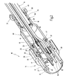
Figure 1
shows an exploded illustration of the components for producing a connecting arrangement in accordance with one preferred exemplary embodiment of the present invention,
Figure 2
shows a partially cut-away illustration of the connecting arrangement in the assembled state of the individual components, and
Figure 3
shows a schematic, perspective illustration of a part of a crimping tool for achieving a connecting arrangement in a variant relating to figure 2.
The essentially cylindrical connecting arrangement 10 illustrated in figures 1 and 2 serves the purpose of mechanically and possibly electrically, for electromagnetic shielding, connecting a multi-core cable 11 to a plugging region 13 of a plug connector part 14, the individual cores 12 of the cable 11 being connected to the plugging region 13 separately.
Figure 1 shows the cable 11 with in this case, for example, five cores 12, which are surrounded in each case individually and together as a bundle in their region from which the insulation has not been stripped by an insulating sheath 15 or 16. The plug connector part 14 has a two-part insulating body 20, whose rear bushing part 17 in this case accommodates, for example, plug contacts 18, to which the ends, from which the insulation has been stripped, of the individual cores 12 are fixedly connected in a suitable manner, for example by crimping. The plug contacts 18 are accommodated in the bushing part 17 such that they cannot be displaced axially, protrude with their front ends 19 beyond the bushing part 17 and are located within an insulating sleeve 21, which can be axially latched to the bushing part 17, of the insulating body 20 (figure 2). It goes without saying that such an insulating body 20 may instead also be provided with socket contacts.
The two-part insulating body 20 is surrounded by a metallic, stepped connecting sleeve 22, which can be provided in a manner not illustrated in its front region having a smaller diameter with a metric outer thread or bayonet connection part for the mechanical connection to a socket/plug connector part on, for example, a device housing. The connecting sleeve 22 bears axially with its front end face 27 on a shoulder 28 of the insulating sleeve 21. The region of the connector sleeve 22 which has a greater diameter is provided on the side of the outer circumference with a knurl having a good grip.
The bushing part 17 of the insulating body 20 is provided at its end region, which accommodates the connecting region of plug contacts 18 and cores 12, with two axially spaced-apart annular grooves 23 and 24, in which in each case an O- ring 25 or 26 is inserted. In one variant (not shown), the two O- rings 25, 26 are replaced by a sealing collar provided with a corresponding axial extent.
A metal sleeve 30, which is profiled in the longitudinal direction and is produced from stainless steel having thin walls, is pushed over the cable 11. The rear end, which faces the cable 11, of the metal sleeve 30 is provided with a raised annular flange 31, whereas the front end, which faces the plugging region 13, of the metal sleeve 30 is provided with two annular attachments or beads 32 and 33 which are directed radially outwards. The metal sleeve 30 passes conically from a region having a smaller diameter and surrounding the cable 11 to a region having a larger diameter, into which the bushing part 17 of the insulating body 20 fits, and over which the region having the larger diameter of the connector sleeve 22 fits.
In the exemplary embodiment illustrated, the cable 11 is provided with a shielding braid 35, which, once the insulating sheath 16 is exposed, comes to lie on a metallic cup-shaped sleeve 34, which is pushed over the insulating sheath 16, such that it is turned back over a certain axial length.
Furthermore, the connecting arrangement 10 is provided with a metallic, annular spring basket 36, which is accommodated between the two annular beads 32 and 33 on the side of the outer circumference on the metal sleeve 30.
The metal sleeve 30 acts as a protective housing and, in the exemplary embodiment, also acts as a shielding housing which provides, in a simple and rapid manner, a mechanically fixed connection and, in the exemplary embodiment, also an electrical shielding connection between the cable 11 and the plugging region 13 or its insulating body 20 or its metallic connector sleeve 22. For this purpose, initially the cores 12 are connected to the plug contacts 18, and said plug contacts 18 are inserted in a latching manner in the bushing part 17 of the insulating body 20. The two O- rings 25 and 26 are fitted over the insulating body 20, and the insulating sleeve 21 is plugged onto the bushing part 17 in a latching manner, and the connector sleeve 22, which has already been threaded on, is fitted over the insulating sleeve 21 up to its annular shoulder 28.
Then, the metal sleeve 30 is fitted with the spring basket 36, which is fitted between the two annular beads 32 and 33, over the bushing part 17 provided with the O- rings 25, 26 and under the rear part, having a larger diameter, of the connector sleeve 22, the metallic spring basket 36 bearing with resilient prestress on the inner circumference of this part of the metallic connector sleeve 22. This results in a both electrical and mechanically frictional connection between the metal sleeve 30 and the connector sleeve 22.
In this state, three crimping connections 37, 38 and 39 are undertaken on the metal sleeve 30 from its outer circumference. The first crimping connection 37 is made for the purpose of connecting the metal sleeve 30 to the insulating body 20 such that, in the region of the annular groove 23, which protrudes axially from the connector sleeve 22 and is fitted with the O-ring 25, in the bushing part 17, the metal sleeve 30 is pushed in on the circumference side, as a result of which the deformation 47, which protrudes radially inwards, deforms the O-ring 25 and partially engages in the annular groove 23. As a result, both a moisture-tight and a mechanically fixed, in the axial direction, connection is achieved. Owing to the high level of friction between the metal sleeve 30 and the O-ring 25, a connection is also achieved which is fixed against rotation.
A second crimping connection 39 is made via an annular region of the metal sleeve 30 close to the annular flange 31 acting so as to protect the cable from bending such that the deformation 49, which protrudes radially inwards, compresses the insulating sheath 16 of the cable 11, as a result of which a connection can likewise be achieved which is moisture-tight and is mechanically resistant to tensile stress and is fixed against rotation.
In the exemplary embodiment illustrated, in which the cable 11 is provided with the cup-shaped sleeve 34 and the turned-back shielding braid 35, a third crimping connection 38 is made such that the deformation 48, which protrudes radially inwards, of the metal sleeve 30 clamps onto the shielding braid 35 on the circumference side, with the result that the metal sleeve 30 takes on the electromagnetic shielding of the cable cores 12, from which the insulation has been stripped, and the connection of said cores 12 to the plug contacts 18 in the insulating body 20, and, as mentioned, transfers the shielding onto the connector sleeve 22 and over said connector sleeve 22, uninterrupted, onto a further plug connector part.
In the drawing, the bead- like deformations 47, 48, 49, which protrude radially inwards, of the crimping connections 37 to 39 are of identical design, i.e. the height of the deformations 47 to 49, which protrude radially inwards, is the same over the entire inner circumference.
In one exemplary embodiment which is not illustrated in detail, the deformations 47 to 49 of the crimping connections 37 to 39 are such that they have a maximum height or a minimum height at in each case two diametrically opposite regions. In other words, over in each case a range of 180°, the deformations 47 to 49 are, with respect to their height (radial dimension), in the form of a sickle, when viewed in the axial direction, such that they extend constantly from a height close to or equal to zero over a maximum height again to a height close to or equal to zero.
This configuration of the bead-like deformations 47 to 49, which protrude radially inwards, is made with a crimping tool 40, which is illustrated schematically and only partially in figure 3, and which comprises two half-shells 41, each half-shell 41 having on the inside, when viewed in the circumferential direction, a shaping projection 42, which points radially inwards, and whose spacing, extending radially inwards, from the inner circumference face 43 of the tool half-shell 41 extends from a value close to or equal to zero over a maximum value again to a value close to or equal to zero, i.e. is in the form of a sickle when viewed axially.
This configuration of the two tool half-shells 41 has the advantage that at the point where the two tool half-shells 41 meet one another radially, i.e. in the separation plane, no deformation of the metal sleeve 30 is brought about during the crimping operation in the axial direction.
Owing to the design or the connection described, a structurally very small connecting apparatus 10 is achieved which has, for example, a maximum diameter of approximately 15 mm and a length from the end of the closure sleeve 21 to the remote end 31 of the metal sleeve 30 of approximately 55 mm.
Mention should also be made of the fact that this connecting arrangement can also be used in the case of single-core cables and, in this case, in particular in the case of coaxial cables.

Claims (14)

  1. Electrical and mechanical connecting arrangement (10) comprising a preferably multi-core cable (11) and a cylindrical plug connector part (14) in the form of a plug or a socket, the cores (12) of the cable (11) being connectable or connected to socket or plug contacts (18) which are held in an electrical insulating body (20) of the plug connector part (14), characterized in that a metal sleeve (30) is provided, which reaches from an end region, provided with an insulating sheath (16), of the cable (11) up to an end region, remote from the plugging region (13), of the insulating body (20), and which can be crimped or is crimped in certain length sections on the circumference side, on the one hand, with the cable insulating sheath (16) and, on the other hand, with the insulating body (20).
  2. Connecting arrangement according to claim 1, characterized in that the crimping deformation (47), which points radially inwards, of the metal sleeve (30) engages in a circumferential groove (23) in the insulating body (20).
  3. Connecting arrangement according to claim 2, characterized in that a sealing element (25) is provided in the region of the circumferential groove (23) in the insulating body (20).
  4. Connecting arrangement according to at least one of claims 1 to 3, characterized in that the crimping deformation (47, 48, 49), which points radially inwards, of the metal sleeve (30) has a different height along its inner circumference.
  5. Connecting arrangement according to claim 4, characterized in that the crimping deformation (47, 48, 49), which points radially inwards, of the metal sleeve (30) has, over in each case 180°, a height which extends in the form of a sickle.
  6. Connecting arrangement, in which the cable (11) has an outer shield (35), according at least to one of the preceding claims, characterized in that the shield (35) is laid back at one end over the cable insulating sheath (16), and in that the metal sleeve (30) can be crimped or is crimped with the laid-back shield (35) along said shield (35).
  7. Connecting arrangement according to claim 6, characterized in that a cup-shaped sleeve (34) is arranged between the cable insulating sheath (16) and the turned-back shield (35).
  8. Connecting arrangement according to claim 6 or 7, characterized in that the metal sleeve (30) is provided, at its end which is on the side of the insulating part, with an electrical connection (36) to a shield part (27) on the plug connector part (14).
  9. Connecting arrangement according to claim 8, characterized in that the electrical connection is formed by a metallic spring basket (36) and the shield part is formed by a metallic connector sleeve (22).
  10. Connecting arrangement according to at least one of the preceding claims, characterized in that the metal sleeve (30) is profiled in terms of its diameter.
  11. Connecting arrangement according to at least one of the preceding claims, characterized in that the metal sleeve (30) has thin walls and is made of stainless steel.
  12. Connecting arrangement according to at least one of the preceding claims, characterized in that the metal sleeve (30) is provided at its cable-side end with a flared flange (31) which protrudes radially outwards.
  13. Tool (40) for producing a crimping connection (37, 38, 39) on an electrical and mechanical connecting arrangement according to claim 1 and, possibly, one of the subsequent claims, characterized by two identical tool half-shells (41), which have, on the side of the inner circumference, a shaping projection (42) having a height profile which points radially inwards and, when viewed axially, is in the form of a sickle.
  14. Tool according to claim 13, characterized in that the height of the sickle-shaped shaping projection (42) on the separating plane of the tool is close to or equal to zero.
EP05006209A 2004-04-06 2005-03-22 Electrical and mechanical connecting arrangement Withdrawn EP1585196A1 (en)

Applications Claiming Priority (2)

Application Number Priority Date Filing Date Title
DE102004018430 2004-04-06
DE102004018430A DE102004018430A1 (en) 2004-04-06 2004-04-06 Electrical and mechanical connection arrangement

Publications (1)

Publication Number Publication Date
EP1585196A1 true EP1585196A1 (en) 2005-10-12

Family

ID=34895587

Family Applications (1)

Application Number Title Priority Date Filing Date
EP05006209A Withdrawn EP1585196A1 (en) 2004-04-06 2005-03-22 Electrical and mechanical connecting arrangement

Country Status (3)

Country Link
US (1) US7101223B2 (en)
EP (1) EP1585196A1 (en)
DE (1) DE102004018430A1 (en)

Cited By (1)

* Cited by examiner, † Cited by third party
Publication number Priority date Publication date Assignee Title
CN101599608B (en) * 2008-06-02 2011-09-28 中航光电科技股份有限公司 Short connected device and multi-core socket with same

Families Citing this family (16)

* Cited by examiner, † Cited by third party
Publication number Priority date Publication date Assignee Title
JP4527019B2 (en) * 2005-07-13 2010-08-18 住友電装株式会社 Shield connector
US7390209B2 (en) * 2006-02-22 2008-06-24 Wealleys Technologies Co., Ltd. Water-proof electric connector module
JP2008108675A (en) * 2006-10-27 2008-05-08 Toshiba Corp Plug
US7534138B1 (en) 2007-12-13 2009-05-19 Delphi Technologies, Inc. Electrical cable shielding terminal
JP5003583B2 (en) * 2008-04-25 2012-08-15 オムロン株式会社 connector
US20100029113A1 (en) * 2008-07-30 2010-02-04 Smith Iii Robert L Cable connector assembly
JP2010061891A (en) * 2008-09-02 2010-03-18 Hitachi Cable Ltd Connector
US8282138B2 (en) * 2008-12-18 2012-10-09 Rostra Tool Company Crimp ring
CN102031937B (en) * 2009-09-30 2013-06-05 西安威尔罗根能源科技有限公司 Maintenance-free anti-looseness insulating pup joint
EP2583355B1 (en) 2010-06-16 2015-03-04 Federal-Mogul Powertrain, Inc. Emi connector ferrule and assembly combination therewith
US9293858B2 (en) * 2014-05-26 2016-03-22 Bren-Tronics, Inc. Screw down connector
US9465183B2 (en) 2014-05-30 2016-10-11 Commscope Technologies Llc Metal armored break-out cable assembly with grounding feature
EP3203586B1 (en) * 2016-02-02 2020-07-22 Yazaki Europe Ltd Electrical connector
US9680268B1 (en) * 2016-05-18 2017-06-13 Itt Manufacturing Enterprises Llc Genderless electrical connectors
CN206806628U (en) * 2017-03-22 2017-12-26 泰科电子(上海)有限公司 Connector
US10985493B1 (en) * 2019-10-04 2021-04-20 R.A. Phillips Industries, Inc. Electrical connector

Citations (6)

* Cited by examiner, † Cited by third party
Publication number Priority date Publication date Assignee Title
DE964291C (en) * 1953-03-31 1957-05-23 Kalart Company Inc Two-wire connection cable for flashing lights
FR1448436A (en) * 1964-09-22 1966-08-05 Amp Inc Coaxial pin plug
US4897050A (en) * 1989-03-30 1990-01-30 Ntt, Inc. Method and apparatus for making coaxial couplings
US5499934A (en) * 1993-05-27 1996-03-19 Cabel-Con, Inc. Hexagonal crimp connector
US6250963B1 (en) * 1999-08-30 2001-06-26 Osram Sylvania Inc. Connector shell, connector assembly and method of fabricating same
US20020119699A1 (en) * 2001-02-28 2002-08-29 Harting Automotive Gmbh & Co. Kg Plug connector

Family Cites Families (15)

* Cited by examiner, † Cited by third party
Publication number Priority date Publication date Assignee Title
US3539976A (en) * 1968-01-04 1970-11-10 Amp Inc Coaxial connector with controlled characteristic impedance
US4634208A (en) * 1983-01-31 1987-01-06 Amp Incorporated Electrical plug connector and method of terminating a cable therewith
US4583809A (en) * 1984-04-02 1986-04-22 Allied Corporation Electrical connector assembly having means for EMI shielding
US4614398A (en) * 1984-12-21 1986-09-30 Simmonds Precision Shielded cable terminal connection
US4799902A (en) * 1987-08-19 1989-01-24 Amp Incorporated Triaxial electrical cable connector
US5083943A (en) * 1989-11-16 1992-01-28 Amphenol Corporation Catv environmental f-connector
DE9007300U1 (en) * 1990-05-11 1991-04-11 Richard Hirschmann Gmbh & Co, 7300 Esslingen, De
US5102351A (en) * 1990-11-29 1992-04-07 The United States Of America As Represented By The Secretary Of The Air Force Shielded electric cable and harness with strain relief
US5888097A (en) * 1997-02-13 1999-03-30 Harco Laboratories, Inc. Backshell assembly for repairable cable assembly
DE19726005A1 (en) * 1997-06-19 1999-02-04 Itt Mfg Enterprises Inc Rear housing
US5879191A (en) * 1997-12-01 1999-03-09 Gilbert Engineering Co, Inc. Zip-grip coaxial cable F-connector
US5997350A (en) * 1998-06-08 1999-12-07 Gilbert Engineering Co., Inc. F-connector with deformable body and compression ring
US6857902B2 (en) * 2001-02-21 2005-02-22 I F M Electronics Gmbh Proximity switch and a cable terminal part unit and a process for its manufacture
US6817896B2 (en) * 2003-03-14 2004-11-16 Thomas & Betts International, Inc. Cable connector with universal locking sleeve
US6733336B1 (en) * 2003-04-03 2004-05-11 John Mezzalingua Associates, Inc. Compression-type hard-line connector

Patent Citations (6)

* Cited by examiner, † Cited by third party
Publication number Priority date Publication date Assignee Title
DE964291C (en) * 1953-03-31 1957-05-23 Kalart Company Inc Two-wire connection cable for flashing lights
FR1448436A (en) * 1964-09-22 1966-08-05 Amp Inc Coaxial pin plug
US4897050A (en) * 1989-03-30 1990-01-30 Ntt, Inc. Method and apparatus for making coaxial couplings
US5499934A (en) * 1993-05-27 1996-03-19 Cabel-Con, Inc. Hexagonal crimp connector
US6250963B1 (en) * 1999-08-30 2001-06-26 Osram Sylvania Inc. Connector shell, connector assembly and method of fabricating same
US20020119699A1 (en) * 2001-02-28 2002-08-29 Harting Automotive Gmbh & Co. Kg Plug connector

Cited By (1)

* Cited by examiner, † Cited by third party
Publication number Priority date Publication date Assignee Title
CN101599608B (en) * 2008-06-02 2011-09-28 中航光电科技股份有限公司 Short connected device and multi-core socket with same

Also Published As

Publication number Publication date
US7101223B2 (en) 2006-09-05
DE102004018430A1 (en) 2005-10-27
US20050221670A1 (en) 2005-10-06

Similar Documents

Publication Publication Date Title
EP1585196A1 (en) Electrical and mechanical connecting arrangement
CN113451800B (en) Plug connector device with compensation sleeve
CN107438926B (en) Method for producing a plug connector device
US7811133B2 (en) Shielded electrical connector with a spring arrangement
US4307926A (en) Triaxial connector assembly
US7179121B1 (en) Coaxial cable connector
US4431254A (en) Connector element for an armoured cable with two multico-core conductors
US5181861A (en) Manually installable coaxial cable connector
CN107210544B (en) Plug connector assembly with compensation crimping part
US5496968A (en) Shielded cable connecting terminal
US5660565A (en) Coaxial cable connector
GB2079549A (en) Coaxial cable connector
US7070440B1 (en) Coaxial cable insulation displacement connector
US3757278A (en) Subminiature coaxial contact
JP6261780B2 (en) Cable connection parts
US3453377A (en) Grounding connector
US11381028B2 (en) Connector for hardline coaxial cable
JP7128511B2 (en) shield connector
JP6951200B2 (en) Electrical connector
JP2006024499A (en) Connector for coaxial cable
US5672079A (en) Coaxial connector for manufacturing a coaxial high frequency cable
US4444454A (en) Field installable coaxial plug connector
US4480887A (en) Angle plug connector
KR101709293B1 (en) coaxial connecter
US9071012B1 (en) Coaxial cable connector

Legal Events

Date Code Title Description
PUAI Public reference made under article 153(3) epc to a published international application that has entered the european phase

Free format text: ORIGINAL CODE: 0009012

AK Designated contracting states

Kind code of ref document: A1

Designated state(s): AT BE BG CH CY CZ DE DK EE ES FI FR GB GR HU IE IS IT LI LT LU MC NL PL PT RO SE SI SK TR

AX Request for extension of the european patent

Extension state: AL BA HR LV MK YU

17P Request for examination filed

Effective date: 20060126

AKX Designation fees paid

Designated state(s): AT BE BG CH CY CZ DE DK EE ES FI FR GB GR HU IE IS IT LI LT LU MC NL PL PT RO SE SI SK TR

17Q First examination report despatched

Effective date: 20080317

STAA Information on the status of an ep patent application or granted ep patent

Free format text: STATUS: THE APPLICATION IS DEEMED TO BE WITHDRAWN

18D Application deemed to be withdrawn

Effective date: 20080930