EP1584731A2 - Dry cleaner and corresponding drying machine - Google Patents
Dry cleaner and corresponding drying machine Download PDFInfo
- Publication number
- EP1584731A2 EP1584731A2 EP05005498A EP05005498A EP1584731A2 EP 1584731 A2 EP1584731 A2 EP 1584731A2 EP 05005498 A EP05005498 A EP 05005498A EP 05005498 A EP05005498 A EP 05005498A EP 1584731 A2 EP1584731 A2 EP 1584731A2
- Authority
- EP
- European Patent Office
- Prior art keywords
- refrigerant
- water
- cooling
- washing liquid
- heat
- Prior art date
- Legal status (The legal status is an assumption and is not a legal conclusion. Google has not performed a legal analysis and makes no representation as to the accuracy of the status listed.)
- Withdrawn
Links
- 238000001035 drying Methods 0.000 title claims abstract description 128
- 239000003507 refrigerant Substances 0.000 claims abstract description 249
- 238000005406 washing Methods 0.000 claims abstract description 196
- 238000001816 cooling Methods 0.000 claims abstract description 179
- 239000007788 liquid Substances 0.000 claims abstract description 151
- 238000010438 heat treatment Methods 0.000 claims abstract description 61
- CURLTUGMZLYLDI-UHFFFAOYSA-N Carbon dioxide Chemical compound O=C=O CURLTUGMZLYLDI-UHFFFAOYSA-N 0.000 claims abstract description 51
- 229910002092 carbon dioxide Inorganic materials 0.000 claims abstract description 27
- 239000001569 carbon dioxide Substances 0.000 claims abstract description 27
- XLYOFNOQVPJJNP-UHFFFAOYSA-N water Substances O XLYOFNOQVPJJNP-UHFFFAOYSA-N 0.000 claims description 82
- 239000000498 cooling water Substances 0.000 claims description 54
- 239000007789 gas Substances 0.000 description 48
- 239000002904 solvent Substances 0.000 description 26
- 238000001704 evaporation Methods 0.000 description 23
- 230000008020 evaporation Effects 0.000 description 22
- 238000010586 diagram Methods 0.000 description 17
- 238000000034 method Methods 0.000 description 13
- 239000003921 oil Substances 0.000 description 12
- 239000003208 petroleum Substances 0.000 description 8
- XUIMIQQOPSSXEZ-UHFFFAOYSA-N Silicon Chemical compound [Si] XUIMIQQOPSSXEZ-UHFFFAOYSA-N 0.000 description 6
- 238000009825 accumulation Methods 0.000 description 6
- 229910052710 silicon Inorganic materials 0.000 description 6
- 239000010703 silicon Substances 0.000 description 6
- 230000006835 compression Effects 0.000 description 5
- 238000007906 compression Methods 0.000 description 5
- 230000007613 environmental effect Effects 0.000 description 4
- 230000000630 rising effect Effects 0.000 description 3
- 238000009835 boiling Methods 0.000 description 2
- 230000000694 effects Effects 0.000 description 2
- 238000009434 installation Methods 0.000 description 2
- 230000002093 peripheral effect Effects 0.000 description 2
- 230000005855 radiation Effects 0.000 description 2
- 239000002918 waste heat Substances 0.000 description 2
- 230000003111 delayed effect Effects 0.000 description 1
- 238000007599 discharging Methods 0.000 description 1
- 239000000446 fuel Substances 0.000 description 1
- 230000020169 heat generation Effects 0.000 description 1
- 238000007689 inspection Methods 0.000 description 1
- 238000012423 maintenance Methods 0.000 description 1
- 238000004519 manufacturing process Methods 0.000 description 1
- 238000013021 overheating Methods 0.000 description 1
- 238000007789 sealing Methods 0.000 description 1
Images


Classifications
-
- D—TEXTILES; PAPER
- D06—TREATMENT OF TEXTILES OR THE LIKE; LAUNDERING; FLEXIBLE MATERIALS NOT OTHERWISE PROVIDED FOR
- D06F—LAUNDERING, DRYING, IRONING, PRESSING OR FOLDING TEXTILE ARTICLES
- D06F43/00—Dry-cleaning apparatus or methods using volatile solvents
- D06F43/007—Dry cleaning methods
-
- D—TEXTILES; PAPER
- D06—TREATMENT OF TEXTILES OR THE LIKE; LAUNDERING; FLEXIBLE MATERIALS NOT OTHERWISE PROVIDED FOR
- D06F—LAUNDERING, DRYING, IRONING, PRESSING OR FOLDING TEXTILE ARTICLES
- D06F43/00—Dry-cleaning apparatus or methods using volatile solvents
- D06F43/08—Associated apparatus for handling and recovering the solvents
- D06F43/086—Recovering the solvent from the drying air current
Definitions
- the present invention relates to a dry cleaner which executes steps of washing•dewatering and drying clothing in a drum using a solvent such as silicon as a washing liquid.
- the present invention relates to a drying machine comprising a water-cooling type heat exchanger for taking heat of a refrigerant which enters expansion means.
- a petroleum-based solvent has heretofore been supplied into a drum. After washing clothing, the solvent in the drum is discharged to rotate the drum at a high speed, and the clothing is dewatered. Moreover, to dry the clothing, dry air (high-temperature air) is circulated in the drum, the solvent is evaporated from the clothing, and drying is performed (see, e.g., Japanese Patent Application Laid-Open No. 8-173688).
- a drying machine in which an electric heater or a gas burning heater is used as a heat source. After heating outside air by the electric heater or the burning heater to form high-temperature air, the air is blown into a storage chamber in which a matter to be dried is stored to thereby dry the matter to be dried in the storage chamber. Moreover, the high-temperature air in the storage chamber, which has dried the matter to be dried, is discharged to the outside.
- a heat generation efficiency ratio of a generated heat amount with respect to projected power
- the drying machine using the gas burning heater has a problem that equipment works such as gas piping and exhaust duct are required at the time of installation of the device.
- a clothing drying machine which is constituted of a compressor, a heating coil, an expansion valve, and a cooling coil.
- a heat pump capable of circulating a heat exchange medium is utilized.
- the matter to be dried is dried by the high-temperature air heated by the heating coil.
- Moisture evaporated from the dried matter is condensed by the cooling coil, and removed, and a condensed water content is discarded (see, e.g., Japanese Patent Application Laid-Open No. 11-99299).
- the present invention has been developed to solve the conventional technical problem, and an object thereof is to provide a dry cleaner in which an installing operation is facilitated and in which environments are taken into consideration.
- a dry cleaner of the present invention rotates a drum containing clothing, and successively executes a washing step using a washing liquid, a dewatering step, and a drying step, and heating means and cooling means for executing the respective steps comprise a heat pump device.
- carbon dioxide is used as a refrigerant of a refrigerant circuit constituting the heat pump device.
- the dry cleaner of the present invention heats the washing liquid by the heat pump device in the above-described inventions.
- the dry cleaner of the present invention cools the washing liquid by the heat pump device in the above-described inventions.
- the dry cleaner of the present invention heats air supplied to the drum in the drying step by the heat pump device in the above-described inventions
- the dry cleaner cools the air discharged from the drum in the drying step by the heat pump device in the above-described inventions.
- the heating means and cooling means for executing the respective steps comprise the heat pump device.
- Both the heating means and the cooling means for heating or cooling the washing liquid, heating the air supplied to the drum in the drying step, and further cooling the air discharged from the drum comprise the heat pump device, and it is possible to remove a boiler and the like which have heretofore been used. Consequently, an installing operation is simplified as compared with the conventional dry cleaner.
- the heating and cooling are performed in the dry cleaner utilizing a heat radiating function and a heat absorbing function obtained by a heat pump. Therefore, as compared with the dry cleaner which performs the heating and cooling using a special device, energy efficiency is remarkably improved, and this can also contribute to environmental problems.
- a valve for switching a refrigerant channel is disposed in the refrigerant circuit constituting the heat pump device in the above-described inventions.
- the valve for switching the refrigerant channel is disposed in the refrigerant circuit constituting the heat pump device. Therefore, when the refrigerant channel of a heat pump of one system is switched, both the heating/cooling of the washing liquid and the heating/cooling of the air for use in the drying can be performed.
- the dry cleaner of the present invention comprises water cooling means for cooling the refrigerant of the heat pump device in the above-described inventions.
- the water cooling means for cooling the refrigerant of the heat pump device since the water cooling means for cooling the refrigerant of the heat pump device is disposed, heat accumulated in the heat pump device is discarded to the water cooling means, and an air cooling capability can be enhanced.
- the above-described inventions comprise auxiliary heating means for heating the air supplied to the drum in the drying step.
- a time required for the drying step can further be shortened.
- the dry cleaner of the present invention heats the washing liquid by the heat pump device in the washing step in the above-described inventions.
- the washing liquid is heated by the heat pump device in the washing step, the temperature of the washing liquid is raised early in the morning in winter, and accordingly a washing ability can be quickly secured.
- the washing liquid is heated by a high-temperature refrigerant discharged from the compressor constituting the refrigerant circuit of the heat pump device, a pressure of the refrigerant is reduced by a pressure reducing device, and thereafter the refrigerant is evaporated to thereby cool the washing liquid.
- the washing liquid is heated by the high-temperature refrigerant discharged from the compressor constituting the refrigerant circuit of the heat pump device, the pressure of the refrigerant is reduced by the pressure reducing device, and thereafter the refrigerant is evaporated to thereby cool the washing liquid. Therefore, special heat absorbing means does not have to be disposed in heating the washing liquid, and a piping constitution is simplified. Also in this case, since a temperature rise corresponding to a power amount input into the heat pump device is obtained in the washing liquid, there is not any problem.
- the heat pump device comprises a plurality of systems of refrigerant circuits.
- the heat pump device comprises the plurality of systems of refrigerant circuits
- the number of the refrigerant circuits may be set in accordance with a process capability required for the dry cleaner, and it is possible to obtain a required heating/cooling capability with respect to each process capability.
- an object of the present invention is to improve a heating capability of drying air at the start of the drying step of a drying machine, so that a drying time can be shortened.
- a drying machine comprising: a storage chamber containing a matter to be dried; and a heat pump comprising a refrigerant circuit including a compressor, a radiator, expansion means, an evaporator and the like. Washing, dewatering, and drying steps for the matter to be dried are executed in the storage chamber, refrigerant discharged from the compressor in the drying step is passed through the radiator, expansion means, and evaporator, and air is circulated in the evaporator from the radiator through the storage chamber to thereby dry the matter to be dried in the storage chamber.
- the drying machine further comprises: a water-cooling heat exchanger for taking heat of the refrigerant entering the expansion means; and control means for controlling whether to circulate cooling water in the water-cooling heat exchanger or to store the cooling water in the water-cooling heat exchanger.
- the control means performs a heat accumulating operation for passing the refrigerant discharged from the compressor into the water-cooling heat exchanger in the washing and dewatering steps and storing the cooling water in the water-cooling heat exchanger to thereby accumulate heat in the water-cooling heat exchanger.
- the above-described invention comprises a bypass piping for bypassing the radiator to pass the refrigerant, and the control means passes the refrigerant through the bypass piping in the heat accumulating operation to store the cooling water in the water-cooling heat exchanger.
- the drying machine comprises: the storage chamber containing the matter to be dried; and the heat pump comprising the refrigerant circuit including the compressor, radiator, expansion means, evaporator and the like.
- the washing, dewatering, and drying steps for the matter to be dried are executed in the storage chamber, the refrigerant discharged from the compressor in the drying step is passed through the radiator, expansion means, and evaporator, and the air is circulated in the evaporator from the radiator through the storage chamber to thereby dry the matter to be dried in the storage chamber.
- the drying machine further comprises: the water-cooling heat exchanger for taking heat of the refrigerant entering the expansion means; and the control means for controlling whether to circulate the cooling water in the water-cooling heat exchanger or to store the cooling water in the water-cooling heat exchanger.
- the control means performs the heat accumulating operation for passing the refrigerant discharged from the compressor into the water-cooling heat exchanger in the washing and dewatering steps and storing the cooling water in the water-cooling heat exchanger to thereby accumulate the heat in the water-cooling heat exchanger.
- the control means passes the refrigerant through the bypass piping which bypasses the radiator in the heat accumulating operation. Accordingly, the cooling water stored in the water-cooling heat exchanger can be heated and stored before entering the drying step.
- the heat accumulated in the water-cooling heat exchanger can be conveyed to the radiator by the refrigerant, the temperature of the drying air is quickly raised at the start of the drying step, and a drying time can be shortened.
- carbon dioxide is used as the refrigerant of the refrigerant circuit.
- carbon dioxide is used as the refrigerant, and the refrigerant on a high-pressure side is brought into a supercritical state. Accordingly, the refrigerant is not condensed in the radiator, remains in the supercritical state, and can exchange the heat with air. Therefore, since the heat exchange capability is high, a drying time can further be reduced.
- control means circulates the cooling water in the water-cooling heat exchanger in a case where temperature of the cooling water stored in the water-cooling heat exchanger rises at a predetermined upper-limit temperature during the heat accumulating operation.
- the cooling water is circulated in the water-cooling heat exchanger in the case where the temperature of the cooling water stored in the water-cooling heat exchanger rises at the predetermined upper-limit temperature during the heat accumulating operation. Then, breakage of the apparatus by boiling of the cooling water in the water-cooling heat exchanger, and overheating of the compressor can be avoided in advance.
- control means stops circulation of the cooling water into the water-cooling heat exchanger from start of the drying step until the temperature of the air passed through the storage chamber rises at the predetermined upper-limit temperature.
- the circulation of the cooling water into the water-cooling heat exchanger is stopped from the start of the drying step until the temperature of the air passed through the storage chamber rises at the predetermined upper-limit temperature. Then, the temperature of the drying air at the start of the drying step can be further quickly raised.
- FIG. 1 shows a constitution diagram of a dry cleaner 1 according to one embodiment of the present invention.
- FIG. 8 shows a rear perspective view of the dry cleaner 1
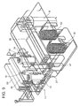
- FIG. 9 shows a perspective view of a heat pump device 11 of the dry cleaner 1 in FIG. 8.
- reference numeral 2 denotes a cylindrical drum including a large number of through holes formed in a peripheral wall, clothing is washed by a washing liquid in this drum 2, and subsequently drying is also performed.
- This drum 2 is rotated by a drum motor (not shown), for example, at a speed of 30 to 50 rpm.
- reference numeral 3 denotes a washing liquid circulation channel for circulating the washing liquid in the drum 2, and the washing liquid circulation channel 3 is connected to a washing liquid tank 4, a washing liquid pump 6, a filter 7, a washing liquid temperature control tank 8 and the like.
- the washing liquid pump 6 When the washing liquid pump 6 is operated, the washing liquid is supplied to the drum 2 from the washing liquid tank 4, and the washing liquid in the drum 2 passes through the washing liquid pump 6 and the filter 7, and is fed to the washing liquid temperature control tank 8. Moreover, the washing liquid passed through the washing liquid temperature control tank 8 returns to the washing liquid tank 4 to repeat the circulation.
- environment-friendly silicon solvent
- reference numeral 11 denotes a heat pump device
- the heat pump device 11 comprises two systems of refrigerant circuits 12, 13.
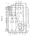
- the refrigerant circuit 12 comprises a compressor 14, an oil separator 16, electromagnetic valves 17 to 23, heat radiating pipes 24 to 26, an expansion valve (pressure reducing device) 27, evaporation pipes 28, 29 and the like.
- the compressor 14 on a discharge side is connected to the oil separator 16, and an outlet of the oil separator 16 is branched into three directions, and connected to the electromagnetic valves 17, 18, 19.
- the electromagnetic valve 18 is further branched, and connected to the electromagnetic valves 21, 22.
- a piping 31 extending from the electromagnetic valve 21 is connected to the expansion valve 27 through a water-cooling heat exchanger 32 which is water cooling means.
- An outlet of the electromagnetic valve 22 is connected to the piping 31 (inlet of the expansion valve 27) extending out of the water-cooling heat exchanger 32.
- an outlet of the electromagnetic valve 19 is connected to the heat radiating pipe 26, and an outlet of the heat radiating pipe 26 is connected to an inlet of the expansion valve 27.
- the heat radiating pipe 26 is disposed in a heat exchanging manner with respect to the washing liquid temperature control tank 8.
- An outlet of the electromagnetic valve 17 is connected to inlets of the electromagnetic valves 21, 22 successively through the heat radiating pipes 24, 25.
- An outlet of the expansion valve 27 is branched, connected to the evaporation pipe 28 through the electromagnetic valve 20 on one hand, and connected to the evaporation pipe 29 through the electromagnetic valve 23 on the other hand.
- the outlets of the respective evaporation pipes 28, 29 are combined, and connected to the compressor 14 on a suction side.
- the evaporation pipe 28 is disposed in the heat exchanging manner with respect to the washing liquid temperature control tank 8.
- a predetermined amount of carbon dioxide (CO 2 ) is sealed as the refrigerant in the refrigerant circuit 12.
- the refrigerant circuit 13 comprises a compressor 34, an oil separator 36, electromagnetic valves 37 to 43, heat radiating pipes 44 to 46, an expansion valve (pressure reducing device) 47, evaporation pipes 48, 49 and the like.
- the compressor 34 on the discharge side is connected to the oil separator 36, and the outlet of the oil separator 36 is branched into three directions, and connected to the electromagnetic valves 37, 38, 39.
- the electromagnetic valve 38 is further branched, and connected to the electromagnetic valves 41, 42.
- a piping 51 extending out of the electromagnetic valve 41 is connected to the expansion valve 47 through a water-cooling heat exchanger 52 which is water cooling means.
- An outlet of the electromagnetic valve 42 is connected to the piping 51 (inlet of the expansion valve 47) extending out of the water-cooling heat exchanger 52.
- an outlet of the electromagnetic valve 39 is connected to the heat radiating pipe 46, and an outlet of the heat radiating pipe 46 is connected to an inlet of the expansion valve 47.
- the heat radiating pipe 46 is disposed in the heat exchanging manner with respect to the washing liquid temperature control tank 8.
- An outlet of the electromagnetic valve 37 is connected to inlets of the electromagnetic valves 41, 42 successively through the heat radiating pipes 44, 45.
- An outlet of the expansion valve 47 is branched, connected to the evaporation pipe 48 through the electromagnetic valve 40 on one hand, and connected to the evaporation pipe 49 through the electromagnetic valve 43 on the other hand.
- the outlets of the respective evaporation pipes 48, 49 are combined, and connected to the compressor 34 on a suction side.
- the evaporation pipe 48 is disposed in the heat exchanging manner with respect to the washing liquid temperature control tank 8.
- the predetermined amount of carbon dioxide (CO 2 ) is also sealed as the refrigerant in the refrigerant circuit 13.
- the heat radiating pipes 24 and 44 of the refrigerant circuits 12, 13 constitute a gas cooler 53
- the heat radiating pipes 25 and 45 constitute a gas cooler 54
- the evaporation pipes 29, 49 constitute an evaporator 56.
- a city water piping 57 is extended through the water-cooling heat exchangers 32, 52 to cool the refrigerant passed through the piping 31, 51.
- reference numeral 58 denotes a water amount adjustment valve which controls a passed water amount through the water-cooling heat exchangers 32, 52.
- reference numeral 61 denotes an air circulation path for circulating the drying air in the drum 2.
- the air circulation path 61 constitutes an air path returning to the drum 2 successively through a fan 62, the evaporator 56, and the gas coolers 54, 53 from the drum 2.
- the fan 62 When the fan 62 is operated, the air in the drum 2 is sucked, and reaches the evaporator 56. After heat exchange in the evaporator, the air successively exchanges the heat with the gas coolers 54, 53, and is blown into the drum 2 to thereby repeat the circulation.
- the air circulation path 61 extending out of the evaporator 56 is provided with a trap 61A, and this trap 61A communicates with the inside of the washing liquid tank 4.
- Auxiliary heating means 63 constituted of a steam or electric heater is disposed in the heat exchanging manner in the air circulation path 61 between the gas cooler 53 and the drum 2. Moreover, these apparatuses are disposed in a main body case (not shown), and operations of the apparatuses are controlled by a controller 64. Especially, the controller 64 controls operation frequencies of the compressors 14, 34 based on a discharged refrigerant pressure and case temperature. Valve open degrees of the respective expansion valves 27, 47 are controlled based on inlet refrigerant temperatures of the evaporation pipes 28, 48, or 29, 49. Furthermore, the passed water amount by the water amount adjustment valve 58 is controlled at a predetermined temperature based on the inlet refrigerant temperatures of the expansion valves 27, 47.
- the controller 64 of the dry cleaner 1 successively executes operation steps of a washing step-dewatering step-recovering•drying step for a predetermined time along a program.
- the heat pump device 11 is successively operated in modes including a preliminary heating (preheating) mode-solvent cooling mode-air heating•solvent cooling mode-usual drying mode-cooling-down mode.
- the controller 64 rotates (repeats forward•backward rotation) the drum 2 at a speed of 30 to 50 rpm, operates the washing liquid pump 6, and circulates the washing liquid in the drum 2 via the washing liquid circulation channel 3.
- the clothing projected in the drum 2 is washed by the rotation of the drum 2 using the washing liquid.
- the controller 64 brings the heat pump device 11 into a preliminary heating mode.
- the controller 64 closes the electromagnetic valves 17, 18, 21, 22, 23 of the refrigerant circuit 12, and opens the electromagnetic valves 19, 20.
- the controller closes the electromagnetic valves 37, 38, 41, 42, 43 of the refrigerant circuit 13, and opens the electromagnetic valves 39, 40.
- the compressors 14, 34 of both the refrigerant circuits 12, 13 are operated.
- a high-temperature•pressure refrigerant compressed into a supercritical state is discharged to the oil separators 16, 36 from the respective compressors 14, 34 on the discharge side, and flows into the heat radiating pipes 26, 46 through the electromagnetic valves 19, 39.
- the high-temperature refrigerant radiates heat, and heats the washing liquid circulated in the washing liquid temperature control tank 8 as described above.
- the refrigerant which has radiated the heat in the heat radiating pipes 26, 46 flows into the expansion valves 27, 47 still in the supercritical state, and is liquefied in a pressure reducing process.
- the refrigerant passes through the electromagnetic valves 20, 40, and flows into the evaporation pipes 28, 48.
- the refrigerant is evaporated, and absorbs the heat from the washing liquid temperature control tank 8 to thereby cool the tank.
- the refrigerant is sucked into the compressors 14, 34 on the suction side.
- the temperatures of the compressors 14, 34 rise by this operation.
- the heating by the heat radiating pipes 26, 46 and the cooling by the evaporation pipes 28, 48 are simultaneously performed.
- the temperature of the washing liquid circulated in the washing liquid temperature control tank 8 gradually rises by the heat corresponding to the power projected in the compressors 14, 34 of the refrigerant circuits 12, 13. Accordingly, a washing effect of the clothing in the drum 2 is enhanced.
- the temperature of the washing liquid is raised early in the morning in winter, and a washing capability can be quickly secured.
- any special heat absorbing means does not have to be disposed in heating the washing liquid, and a piping constitution is simplified.
- the controller 64 operates the compressors 14, 34 at a maximum frequency within limits of discharged refrigerant pressure and case temperature.
- the valve open degrees of the expansion valves 27, 47 are reduced by an overload in a range in which rotation numbers of the compressors 14, 34 do not drop.
- the controller 64 When ending the washing step of the program for a predetermined time, the controller 64 next shifts to a dewatering step.
- the washing liquid circulation channel 3 is switched to a path which bypasses the drum 2 to thereby operate the washing liquid pump 6.
- a liquid discharge valve (not shown) is opened to discharge the washing liquid in the drum 2.
- the drum 2 is rotated (rotated forwards) at a restriction of, for example, 600 to 700 rpm, and the liquid is removed from the clothing.
- the controller 64 brings the heat pump device 11 into a solvent cooling mode.
- the controller 64 closes the electromagnetic valves 17, 19, 22, 23 of the refrigerant circuit 12, and opens the electromagnetic valves 18, 21, 20.
- the controller closes the electromagnetic valves 37, 39, 42, 43 of the refrigerant circuit 13, and opens the electromagnetic valves 38, 41, 40.
- the water amount adjustment valve 58 is opened to pass water into the water-cooling heat exchangers 32, 52 via the city water piping 57.
- the refrigerant passes through the electromagnetic valves 20, 40, and flows into the evaporation pipes 28, 48.
- the refrigerant is evaporated, and absorbs the heat from the washing liquid temperature control tank 8 to thereby cool the tank.
- the refrigerant is sucked into the compressors 14, 34 on the suction side.
- the controller 64 brings the compressors 14, 34 into a maximum frequency within the limits of the discharged refrigerant pressure and case temperature.
- the valve open degrees of the expansion valves 27, 47 are controlled in such a manner as to set the refrigerant entering the evaporation pipes 28, 48 at a predetermined temperature.
- the operation frequencies of the compressors 14, 34 are lowered.
- the compressors 14, 34 are stopped.
- the passed water amounts into the water-cooling heat exchangers 32, 52 are controlled by the water amount adjustment valve 58 in such a manner as to set the refrigerant in the inlets of the expansion valves 27, 47 at a predetermined temperature.
- the controller 64 brings the heat pump device 11 into an air heating•solvent cooling mode immediately (e.g., several minutes) before ending the dewatering step.
- the controller 64 closes the electromagnetic valves 18, 19, 21, 23 of the refrigerant circuit 12, and opens the electromagnetic valves 17, 22, 20.
- the controller also closes the electromagnetic valves 38, 39, 41, 43 of the refrigerant circuit 13, and opens the electromagnetic valves 37, 42, 40.
- the water amount adjustment valve 58 is opened to pass water into the water-cooling heat exchangers 32, 52 from the city water piping 57.
- the refrigerant is cooled there, emanates from the heat radiating pipes 25, 45 while keeping the supercritical state, passes through the electromagnetic valves 22, 42, flows into the expansion valves 27, 47, and is liquefied in a pressure reducing process.
- the refrigerant passes through the electromagnetic valves 20, 40, flows into the evaporation pipes 28, 48, evaporates there, and absorbs the heat from the washing liquid temperature control tank 8 to thereby cool the tank.
- the refrigerant is sucked into the compressors 14, 34 on the suction side.
- the controller 64 brings the compressors 14, 34 into a maximum frequency within the limits of the discharged refrigerant pressure and case temperature.
- the valve open degrees of the expansion valves 27, 47 are controlled in such a manner as to set the refrigerant entering the evaporation pipes 28, 48 at the predetermined temperature. Furthermore, the passed water amounts into the water-cooling heat exchangers 32, 52 are controlled by the water amount adjustment valve 58 in such a manner as to set the refrigerant in the inlets of the expansion valves 27, 47 at a predetermined temperature.
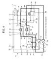
- the electromagnetic valves 21, 41 are opened to pass the refrigerant through the piping 31, 51, and the refrigerant is cooled by water in the water-cooling heat exchangers 32, 52 to thereby lower the temperature (shown by a broken line in FIG. 4). Consequently, the air in the air circulation path 61 is heated, and the washing liquid of the washing liquid temperature control tank 8 is cooled.
- the dewatering step is executed by the program for a predetermined time, and ends midway in the air heating•solvent cooling mode.
- the controller 64 When the dewatering step ends, the controller 64 next shifts to a recovering•drying step.
- the controller 64 operates the fan 62, and further rotates the drum 2.
- the air in the air circulation path 61 is successively sent to the gas coolers 54, 53 through the evaporator 56 as described above. Since the high-temperature•pressure refrigerant is circulated in the heat radiating pipes 24, 25 and the heat radiating pipes 44, 45 of the refrigerant circuits 12, 13 as described above, the air exchanges the heat, and is heated in the gas coolers 54, 53. After the temperature rises, the refrigerant is blown into the drum 2. The washing liquid is evaporated from the clothing in the drum 2 by this high-temperature air.
- the air from which the washing liquid is evaporated in the drum 2 is sucked from the drum 2 by the fan 62, and sent into the evaporator 56 to repeat this circulation.
- the controller 64 brings the heat pump device 11 into a usual drying mode. It is to be noted that the controller 64 once reduces the passed water amounts into the water-cooling heat exchangers 32, 52 by the water amount adjustment valve 58 before shifting to the usual drying mode from the air heating•solvent cooling mode. Alternatively, the water passing is stopped to promote temperature rise of the circulating air in the air circulation path 61 as described later.
- the controller 64 closes the electromagnetic valves 18, 19, 21, 20 of the refrigerant circuit 12, and opens the electromagnetic valves 17, 22, 23 in the subsequent usual drying mode.
- the controller also closes the electromagnetic valves 38, 39, 41, 40 of the refrigerant circuit 13, and opens the electromagnetic valves 37, 42, 43.
- the controller also opens the water amount adjustment valve 58 to pass the water into the water-cooling heat exchangers 32, 52 from the city water piping 57 as described above.
- the refrigerant is cooled there, emanates from the heat radiating pipes 25, 45 while keeping the supercritical state, passes through the electromagnetic valves 22, 42, flows into the expansion valves 27, 47, and is liquefied in the pressure reducing process.
- the refrigerant passes through the electromagnetic valves 23, 43, flows into the evaporation pipes 29, 49, evaporates there, absorbs the heat from the air circulating in the air circulation path 61 around the evaporator 56, and cools the air.
- the washing liquid evaporated in the air by the cooling is condensed on the surface of the evaporator 56.
- the washing liquid liquefied on the surface of the evaporator 56 is recovered into the washing liquid tank 4 from the trap 61A.
- the clothing in the drum 2 is efficiently dried by the heating of the clothing and the recovering of the washing liquid.
- the refrigerant is sucked into the compressors 14, 34 on the suction side.
- the controller 64 brings the compressors 14, 34 into the maximum frequency within the limits of the discharged refrigerant pressure and case temperature.
- the valve open degrees of the expansion valves 27, 47 are controlled in such a manner as to set the refrigerant entering the evaporation pipes 28, 48 at the predetermined temperature.
- the passed water amounts into the water-cooling heat exchangers 32, 52 are controlled by the water amount adjustment valve 58 in such a manner as to set the refrigerant in the inlets of the expansion valves 27, 47 at the predetermined temperature.
- the electromagnetic valves 21, 41 are opened to pass the refrigerant through the piping 31, 51, and the refrigerant is cooled by the water in the water-cooling heat exchangers 32, 52 to thereby lower the temperature (shown by a broken line in FIG. 5).
- the heating of the air into the drum 2 is insufficient, or the drying is quickly performed, the heat is generated by auxiliary heating means 63, and the air in the air circulation path 61, flowing to the drum 2 from the gas cooler 53, is heated. Consequently, a time required for the drying step can be further shortened.
- the controller 64 After executing the usual drying mode by the program for a predetermined time, the controller 64 brings the heat pump device 11 into a cooling-down mode. In this cooling-down mode, the controller 64 continuously operates the fan 62, closes the electromagnetic valves 17, 19, 20, 22 of the refrigerant circuit 12, and opens the electromagnetic valves 18, 21, 23. The controller also closes the electromagnetic valves 37, 39, 40, 42 of the refrigerant circuit 13, and opens the electromagnetic valves 38, 41, 43. The water amount adjustment valve 58 is opened to pass the water into the water-cooling heat exchangers 32, 52 from the city water piping 57 as described above.
- the refrigerant passes through the electromagnetic valves 23, 43, flows into the evaporation pipes 29, 49, evaporates there, absorbs the heat from the air in the air circulation path 61 through the evaporator 56, and cools the air. Thereafter, the refrigerant is sucked into the compressors 14, 34 on the suction side.
- the controller 64 brings the compressors 14, 34 into the maximum frequency within the limits of the discharged refrigerant pressure and case temperature.
- the valve open degrees of the expansion valves 27, 47 are controlled in such a manner as to set the refrigerant in the inlets of the evaporation pipes 29, 49 at the predetermined temperature.
- the passed water amounts into the water-cooling heat exchangers 32, 52 are controlled by the water amount adjustment valve 58 in such a manner as to set the refrigerant in the inlets of the expansion valves 27, 47 at the predetermined temperature.
- the air circulated into the air circulation path 61 exchanges the heat with the evaporator 56, and is cooled.
- the auxiliary heating means 63 does not generate heat. Accordingly, the temperature of the air circulated in the air circulation path 61 drops, and the temperature of the clothing in the drum 2 is lowered.
- the controller 64 stops the operation.
- the heating means and cooling means for executing the respective steps comprise the heat pump device 11. Therefore, both the heating means and the cooling means for heating and cooling the washing liquid, heating the air supplied to the drum 2 in the drying step, and cooling the air discharged from the drum 2 comprise the heat radiating or evaporating pipes of the heat pump device 11. It is possible to remove the boiler and the like which have heretofore been used. Consequently, the installing operation is simplified as compared with the conventional art.
- the heating and cooling in the dry cleaner 1 are performed utilizing a heat radiating function and a heat absorbing function obtained by the heat pump, the energy efficiency is remarkably improved as compared with the heating and cooling performed by a special device, and this can also contribute to environmental problems.
- the environment-friendly dry cleaner 1 can be constituted with respect to the refrigerant. Especially, since a heating capability in the heat radiating pipe is enhanced in the refrigerant circuits 12, 13 using carbon dioxide, it is possible to accelerate the drying process.
- the refrigerant channel of one system of the heat pump constituting the refrigerant circuits 12, 13 is switched by the electromagnetic valve. Consequently, both the heating/cooling of the washing liquid, and the heating/cooling of the air for use in the drying can be performed.
- the above-described heat pump device 11 is disposed in a state in which all components do not have any elevation difference. This produces an advantage that the oil discharged from the compressors 14, 34 easily returns. Since the heat pump device 11 is integrated as shown in FIG. 9, inspection of refrigerant gas leak or sealing of the refrigerant are performed in a manufacturing factory, and productivity is improved. Even if troubles occur, the whole device can be changed, and therefore maintenance•management are facilitated.
- reference numeral 66 denotes a front panel of the dry cleaner 1, an openable/closable door (not shown) for inserting/removing the clothing with respect to the drum 2 is attached to the panel 66. Moreover, the heat pump device 11 is disposed above the drum 2. Accordingly, it is possible to solve the problem that the washing liquid with which the drum 2 is filled flows into the heat pump device 11 in the washing step.
- two systems of the refrigerant circuits 12, 13 constitute the heat pump device 11, and the heat pump device 11 may be constituted by one system of the refrigerant circuit in accordance with the process capability of the dry cleaner 1.
- the number of refrigerant circuits is further increased, and required heating/cooling capability may be obtained.
- silicon is used as the washing liquid (solvent) in the embodiment, but the present invention is not limited to the liquid, and the present invention is effective even in a case where a conventional petroleum-based solvent is used.
- a drying machine capable of reducing a drying time of a matter to be dried.
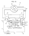
- FIG. 10 shows a schematic constitution diagram of a dry cleaner 101 using, for example, a petroleum-based solvent as a washing liquid in one embodiment of a drying machine to which a heat pump device 103 of the present invention is applied in this case.
- reference numeral 102 denotes a cylindrical drum including a large number of through holes formed in a peripheral wall. Clothing or the like is stored as a matter to be washed (matter to be dried in a recovering•drying step) in a storage chamber 102A in the drum 102. In the storage chamber 102A, steps of washing, dewatering, and drying the clothing by a washing liquid are executed. That is, the dry cleaner 101 performs the washing and the subsequent drying in the storage chamber 102A.
- This drum 102 is rotated by a drum motor (not shown), for example, at a speed of 30 to 50 rpm.
- the drum 102 is connected to a washing liquid circulation channel (not shown) for supplying•discharging the washing liquid with respect to the storage chamber 102A.
- a washing liquid circulation channel In the washing liquid circulation channel, a washing liquid tank (not shown), a washing liquid pump, a filter, a washing liquid cooling tank 106 and the like are connected.
- the washing liquid pump When the washing liquid pump is operated, the washing liquid is supplied to the drum 102 from the washing liquid tank, and the washing liquid in the drum 102 passes through the washing liquid pump and the filter, and is fed to the washing liquid cooling tank 106.
- the washing liquid passed through the washing liquid cooling tank 106 returns to the washing liquid tank to repeat the circulation.
- the washing liquid cooling tank 106 is provided with a cooling tank temperature sensor 137 for detecting the temperature of the washing liquid in the washing liquid cooling tank 106, and connected to a control device 120 described later.
- reference numeral 103 denotes a heat pump device of the present invention
- a refrigerant circuit 104 comprises a compressor 105, electromagnetic valves 107, 108, 123, 124, a gas cooler 109 which is a heat radiator, a capillary tube 110 which is expansion means, an evaporator 111 and the like.
- the compressor 105 for use in the present embodiment is an inner intermediate pressure type multistage compression system rotary compressor.
- an electromotive element, a first rotary compression element (first stage) driven by this electromotive element, and a second rotary compression element (second stage) are disposed.
- a low-pressure refrigerant is introduced into the first rotary compression element of the compressor 105 from a refrigerant introduction tube 116, and a high-temperature•pressure refrigerant compressed by the second rotary compression element is discharged to the outside of the compressor 105 from a refrigerant discharge tube 117.
- the refrigerant discharge tube 117 of the compressor 105 is connected to the electromagnetic valve 107 via the gas cooler 109.
- the refrigerant discharge tube 117 on the inlet side of the gas cooler 109 is connected to a bypass piping 119.
- the bypass piping 119 bypasses the gas cooler 109 to pass the refrigerant.
- the bypass piping 119 is connected to the electromagnetic valve 108.
- An outlet of the electromagnetic valve 107 is connected to a piping 112, and the piping 112 is connected to the capillary tube 110 through a water-cooling heat exchanger 113.
- An outlet of the electromagnetic valve 108 is connected to the piping 112 (inlet side of the water-cooling heat exchanger 113) connected to the outlet of the electromagnetic valve 107.
- the water-cooling heat exchanger 113 is heat discharge means for taking the heat of the refrigerant which enters the capillary tube 110, cooling water (city water) from a city water piping 114 is supplied to the water-cooling heat exchanger 113 to cool the refrigerant passed through the piping 112, and thereafter the water is discharged from a water discharge piping 130.
- the city water piping 114 is provided with a water amount adjustment valve 115 for controlling a passed water amount of the cooling water which enters the water-cooling heat exchanger 113.
- the water discharge piping 130 is provided with a water discharge valve 132 which controls a discharged water amount from the water-cooling heat exchanger 113.
- the water amount adjustment valve 115 and water discharge valve 132 comprise, for example, step motor valves.
- the water-cooling heat exchanger 113 is provided with a heat exchanger temperature sensor 125 for detecting the temperature of the cooling water in the water-cooling heat exchanger 113, and connected to the control device 120.
- the piping 112 passed through the water-cooling heat exchanger 113 is provided with a refrigerant temperature sensor 127 for detecting a refrigerant temperature before expansion.
- the gas cooler 109 is disposed in the heat exchanging manner with respect to an air circulation path 118 described later.
- an outlet of the capillary tube 110 is branched into two directions, connected to the electromagnetic valve 123 on one side, and connected to the electromagnetic valve 124 on the other side.
- the outlet of the electromagnetic valve 123 is connected to the evaporator 111, and the evaporator 111 on the outlet side is connected to the compressor 105 on a suction side via the refrigerant introduction tube 116.
- An outlet of the electromagnetic valve 124 is connected to the refrigerant introduction tube 116 extending out of the evaporator 111 via a piping 128 disposed in the washing liquid cooling tank 106.
- the evaporator 111 is disposed in the heat exchanging manner with respect to the air circulation path 118.
- CO 2 carbon dioxide
- the air circulation path 118 circulates drying air in the drum 102, and constitutes an air path successively passing from the drum 102 through a fan 135, evaporator 111, and gas cooler 109 and returning to the drum 102. Moreover, when the fan 135 is operated, the air in the drum 102 is sucked, reaches the evaporator 111, exchanges the heat in the evaporator, thereafter exchanges the heat with the gas cooler 109, and is blown into the drum 102 to thereby repeat the circulation.
- the air circulation path 118 extending out of the evaporator 111 is provided with a trap 118A, and this trap 118A communicates with the inside of the washing liquid tank.
- Air temperature sensors 138, 139 are disposed in the air circulation path 118 in the vicinity of an outlet/inlet of the drum 102, and these air temperature sensors 138, 139 are capable of detecting the temperature of the air blown into the drum 102 and that of the air emanating from the drum 102.
- control device 120 is control means which controls the dry cleaner 101. Temperatures of the heat exchanger temperature sensor 125, refrigerant temperature sensor 127, cooling tank temperature sensor 137, air temperature sensors 138, 139, and a case containing the respective apparatuses, and a refrigerant pressure discharged from the compressor 105 are connected to an input side. Moreover, the control device 120 controls the operation of the washing liquid pump, the operation of the compressor 105, and the opening/closing of the electromagnetic valves 107, 108, 123, 124 based on the input information. Furthermore, the control device 120 controls whether to pass the cooling water through the water-cooling heat exchanger 113 or to store the cooling water in the water-cooling heat exchanger 113. That is, the control device 120 controls the water amount adjustment valve 115 and the water discharge valve 132 to thereby circulate and store the cooling water with respect to the water-cooling heat exchanger 113.
- the control device 120 of the dry cleaner 101 successively executes operation steps of a washing step (washing step 1 and washing step 2)-dewatering step-recovering•drying step-cooling-down step for a predetermined time along a program.
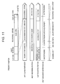
- the heat pump device 103 is successively operated in modes including a solvent cooling mode-recovering•drying mode-cooling-down mode. It is to be noted that a heat absorbing portion of FIG. 11 indicates a portion where the refrigerant absorbs the heat in each operation step.
- the refrigerant exchanges the heat with the washing liquid of the washing liquid cooling tank, and absorbs the heat from the washing liquid.
- the refrigerant exchanges the heat with the circulating air circulating through the 118 by the evaporator 111, and exerts a heat absorbing function.
- a heat radiating portion of FIG. 11 shows a portion in which the refrigerant radiates the heat in each operation step. That is, in the washing step 1, the refrigerant radiates the heat to the cooling water circulating in the water-cooling heat exchanger 113 by the water-cooling heat exchanger 113.
- the heat is radiated into the cooling water stored in the water-cooling heat exchanger 113. Thereafter, the refrigerant exchanges the heat with the circulating air circulating in the air circulation path 118, and radiates the heat by the gas cooler 109.
- the control device 120 rotates (repeats forward•backward rotation) the drum 102 at a speed of 30 to 50 rpm, operates the washing liquid pump, and circulates the washing liquid in the drum 102 via the washing liquid circulation channel.
- the clothing projected in the drum 102 is washed by the rotation of the drum 102 using the washing liquid.
- the control device 120 brings the heat pump device 103 into a solvent cooling mode. That is, as shown in FIG. 12, the control device 120 closes the electromagnetic valves 107, 123, opens the electromagnetic valves 108, 124, and operates the compressor 105 of the refrigerant circuit 104.
- the control device 120 opens the water amount adjustment valve 115 and the water discharge valve 132, so that the cooling water is circulated through the water-cooling heat exchanger 113.
- a high-temperature•pressure carbon dioxide refrigerant compressed into a supercritical state is passed through the refrigerant discharge tube 117 and bypass piping 119 from the discharge side of the compressor 105, and flows into the piping 112 through the electromagnetic valve 108.
- the refrigerant is cooled by the cooling water circulated through the water-cooling heat exchanger 113 while passing through the piping 112, flows into the capillary tube 110 while keeping the supercritical state, and is liquefied in a pressure reducing process.
- the refrigerant passes through the electromagnetic valve 124, and flows into the piping 128 disposed in the heat exchanging manner with respect to the washing liquid cooling tank 106.
- the refrigerant evaporates, and absorbs the heat from the washing liquid cooling tank 106 to thereby cool the tank.
- the washing liquid in the washing liquid cooling tank 106 is cooled at about +25°C.
- the refrigerant discharged from the piping 128 flows into the refrigerant introduction tube 116, and is sucked into the compressor 105 on the suction side.
- the control device 120 controls an operation frequency of the compressor 105 in such a manner as to set a refrigerant entering the piping 128 at the predetermined temperature.
- the operation frequency of the compressor 105 is lowered.
- the compressor 105 is stopped.
- a passed water amount into the water-cooling heat exchanger 113 is controlled in such a manner as to set the refrigerant of the inlet of the capillary tube 110 detected by the refrigerant temperature sensor 127 at the predetermined temperature by the water amount adjustment valve 115. It is to be noted that in the washing step 1, the water discharge valve 132 of the water-cooling heat exchanger 113 is fully opened.
- the control device 120 closes the water amount adjustment valve 115 and the water discharge valve 132 of the water-cooling heat exchanger 113, stops the circulation of the cooling water into the water-cooling heat exchanger 113, and stores the cooling water in the water-cooling heat exchanger 113. That is, the cooling water heated by the heat exchange with the refrigerant in the water-cooling heat exchanger 113 is stored in the water-cooling heat exchanger 113 without being discharged, and temperature rises at about +70°C.
- the control device 120 opens the water amount adjustment valve 115, or the water amount adjustment valve 115 and water discharge valve 132 to thereby circulate the cooling water. Accordingly, it is possible to prevent a disadvantage that the temperature of the cooling water in the water-cooling heat exchanger 113 rises exceeding a predetermined upper-limit value. Therefore, damages on the apparatus by the boiling of the cooling water in the water-cooling heat exchanger 113, or the heating of the compressor 105 can be avoided in advance.
- the control device 120 When ending the washing step (washing steps 1 and 2) of the program for a predetermined time (e.g., six minutes in the present embodiment), the control device 120 next shifts to a dewatering step.
- this dewatering step the operation of the washing liquid pump is stopped, the circulation of the washing liquid is stopped, a liquid discharge valve (not shown) is opened, and the washing liquid in the drum 102 is discharged.
- the drum 102 is rotated (rotated forwards) at a high speed of, for example, 600 to 700 rpm, and the liquid is removed from the clothing.
- the operation of the washing liquid pump is stopped to stop the circulation of the washing liquid in the dewatering step.
- the washing liquid circulation channel may be switched to a path which bypasses the drum 102 to thereby operate the washing liquid pump.
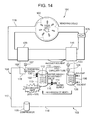
- control device 120 closes the electromagnetic valves 107, 123 of the refrigerant circuit 104, and opens the electromagnetic valves 108, 124 in the same manner as in the respective washing steps (FIG. 14). Furthermore, closed states of the water amount adjustment valve 115 and the water discharge valve 132 of the water-cooling heat exchanger 113 are maintained continuously to the washing step 2.
- a high-temperature•pressure carbon dioxide refrigerant compressed into a supercritical state is discharged to the refrigerant discharge tube 117 from the discharge side of the compressor 105, and flows into the piping 112 through the bypass piping 119 and electromagnetic valve 108.
- the refrigerant is cooled by the cooling water stored in the water-cooling heat exchanger 113 while passing through the piping 112, flows into the capillary tube 110 while keeping the supercritical state, and is liquefied in a pressure reducing process.
- the refrigerant flows into the piping 128 disposed in the heat exchanging manner with respect to the washing liquid cooling tank 106 via the electromagnetic valve 124, evaporates there, and absorbs the heat from the washing liquid cooling tank 106. Thereafter, the refrigerant which has flows out of the piping 128 flows into the refrigerant introduction tube 116, and is sucked into the compressor 105 in a suction side to thereby repeat a cycle. Moreover, when the washing liquid cooling tank 106 is at a predetermined temperature or higher temperature, the control device 120 controls an operation frequency of the compressor 105 in such a manner as to set a refrigerant entering the piping 128 at the predetermined temperature.
- the control device 120 opens the water amount adjustment valve 115, or the water amount adjustment valve 115 and water discharge valve 132 to thereby circulate the cooling water in the same manner as in the washing step 2.
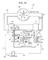
- the dewatering step is performed for a predetermined time (six minutes in the present embodiment), and, as shown in FIG. 15, the control device 120 closes the electromagnetic valve 108 of the refrigerant circuit 104, and opens the electromagnetic valve 107 immediately (one minute in the present embodiment) before ending the dewatering step. It is to be noted that the electromagnetic valve 123 is closed, and the electromagnetic valve 124 remains opened.
- the compressor 105 of the refrigerant circuit 104 When the compressor 105 of the refrigerant circuit 104 is operated in this state, the high-temperature•pressure carbon dioxide refrigerant compressed into the supercritical state is discharged to the refrigerant discharge tube 117 from the discharge side of the compressor 105, and flows into the gas cooler 109.
- the refrigerant radiates the heat there, and heats the air in the air circulation path 118 around the gas cooler 109.
- the refrigerant is passed through the gas cooler 109 to heat the gas cooler 109 in this manner immediately before the end of the dewatering step, and accordingly a heating capability can be improved at the start (rising) of a recovering•drying step in a subsequent stage.
- the control device 120 When the dewatering step ends, the control device 120 next shifts to a recovering•drying step. In this recovering•drying step, the control device 120 operates the fan 135, and further rotates the drum 102. When the fan 135 is operated, the air in the air circulation path 118 is successively sent to the gas cooler 109 through the evaporator 111 as described above. Since the high-temperature•pressure refrigerant of the refrigerant circuit 104 is circulated in the gas cooler 109 as described above, the air exchanges the heat here, and is heated. After the temperature rises, the refrigerant is blown into the drum 102. The washing liquid is evaporated from the clothing in the drum 102 by this high-temperature air.
- the air from which the washing liquid is evaporated in the drum 102 is sucked from the drum 102 by the fan 135, and sent into the evaporator 111. This circulation is repeated. Moreover, the control device 120 brings the heat pump device 103 into a drying mode. It is to be noted that the control device 120 once opens the electromagnetic valve 123 of the refrigerant circuit 104, and closes the electromagnetic valve 124 in the drying mode (FIG. 16).
- the control device 120 also closes the water amount adjustment valve 115 and water discharge valve 132 to stop the circulation of the cooling water into the water-cooling heat exchanger 113 from the start of the recovering•drying step until the temperature of the air passed through the storage chamber 102A of the drum 102, detected by the air temperature sensor 139, rises at a predetermined upper-limit temperature, for example, +60°C.
- the compressor 105 of the refrigerant circuit 104 when the compressor 105 of the refrigerant circuit 104 is operated, the high-temperature•pressure carbon dioxide refrigerant compressed into the supercritical state is discharged to the refrigerant discharge tube 117 from the discharge side of the compressor 105, and flows into the gas cooler 109.
- the refrigerant radiates the heat there, and heats the air circulating in the air circulation path 118 around the gas cooler 109.
- the heated air is discharged into the drum 102 to dry the clothing as described above.
- the refrigerant is cooled there, flows into the piping 112 from the gas cooler 109 through the electromagnetic valve 107 while keeping the supercritical state, passes through the water-cooling heat exchanger 113, and exchanges the heat with the stored cooling water.
- the cooling water stored in the water-cooling heat exchanger 113 is heated by the heat accumulated in the water-cooling heat exchanger 113 from the previous-stage step, the refrigerant is heated for a while in the water-cooling heat exchanger 113 from the start of the recovering•drying step until the accumulated heat amount is discharged.
- the refrigerant which has emanated from the piping 112 flows into the capillary tube 110, and is liquefied in a pressure reducing process.
- the refrigerant flows into the evaporator 111 through the electromagnetic valve 123, evaporates there, absorbs the heat from the air circulating in the air circulation path 118 around the evaporator 111.
- the washing liquid evaporated in the air is condensed on the surface of the evaporator 111.
- the washing liquid liquefied on the surface of the evaporator 111 is recovered in the washing liquid tank from the trap 118A. By this heating of the clothing and the recovering of the washing liquid, the clothing in the drum 102 is efficiently dried.
- the control device 120 opens the water amount adjustment valve 115 and water discharge valve 132, and controls the passed water amount in such a manner as to set an outlet temperature of the drum 102, detected by the air temperature sensor 139, at +60°C.
- the circulation of the cooling water into the water-cooling heat exchanger 113 is stopped until the temperature of the air passed through the storage chamber 102A of the drum 102 rises at a predetermined upper-limit temperature (+60°C). Consequently, the temperature of the drying air at the start of the recovering•drying step can be further quickly raised.
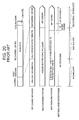
- a circulating air temperature change (drying air temperature change) in the air circulation path 118 in the recovering•drying step will be described with reference to FIG. 18.
- a rapid temperature drop of the outlet (cooler outlet temperature of FIG. 18) of the evaporator 111 at a starting time does not occur by heat accumulation of the water-cooling heat exchanger 113, performed in the previous-stage step, and an effect of passing the refrigerant through the gas cooler 109 immediately before to thereby heat the gas cooler 109.
- the air temperature (inlet temperature of the drum 102) of the inlet of the storage chamber 102A, detected by the air temperature sensor 138 rapidly rises. After the elapse of a predetermined time (A of FIG.
- the temperature reaches a set temperature B (e.g., +65°C in the present embodiment).
- a set temperature B e.g., +65°C in the present embodiment.
- the air temperature (drum 102 outlet temperature) of the storage chamber 102A outlet detected by the air temperature sensor 139, also rises.
- the drum 102, air circulation path 118 and the like are sufficiently warmed (C of FIG. 18), the circulating air is stabilized, and thereafter the temperature rise becomes moderate.
- the water amount adjustment valve 115 and the water discharge valve 132 are opened by the control device 120 to start the circulation of the cooling water of the water-cooling heat exchanger 113.
- the control device 120 adjusts the water amount adjustment valve 115 and the water discharge valve 132 to thereby control the passed water amount in such a manner as to set the outlet temperature of the drum 102, detected by the air temperature sensor 139, at +60°C.
- the heat discharge operation of the water-cooling heat exchanger 113 is started (i.e., in the embodiment, an operation from the start of the washing step 2 until the air temperature of the storage chamber 102A outlet reaches +60°C corresponds to a heat accumulating operation)
- the temperature of the drying air heated by the gas cooler 109 gradually drops. That is, the air temperature in the storage chamber 102A inlet gradually drops.
- the outlet temperature of the evaporator 111 similarly gradually drops.
- the recovering•drying step ends.
- a difference between the storage chamber 102A inlet temperature detected by the air temperature sensor 138 and the storage chamber 102A outlet temperature detected by the air temperature sensor 139 is G.
- the cooling water is stored in the water-cooling heat exchanger 113 before entering the recovering•drying step in this manner, and the stored cooling water is heated to accumulate heat, and the heat accumulated in the water-cooling heat exchanger 113 can be conveyed to the gas cooler 109 by the refrigerant.
- the temperature of the drying air at the start of the recovering•drying step is quickly raised, and a drying time can be shortened.
- the control device 120 executes a control to open the electromagnetic valve 108 while closing the electromagnetic valve 107 in the heat accumulating operation for storing the cooling water in the water-cooling heat exchanger 113. Accordingly, the high-temperature/pressure refrigerant gas compressed by the compressor 105 is passed through the bypass piping 119. That is, during the heat accumulating operation from the start of the heat accumulating operation immediately before the end of the dewatering step, the refrigerant is passed through the water-cooling heat exchanger 113 without being passed through the gas cooler 109. Consequently, the heat can be effectively accumulated in the water-cooling heat exchanger 113.
- the refrigerant on the high-pressure side of the refrigerant circuit 104 is brought into the supercritical state, and the refrigerant can exchange the heat with the air without being condensed in the gas cooler 109 while keeping the supercritical state. Accordingly, since a heat exchange capability in the gas cooler 109 becomes high, the circulating air (drying air) can be efficiently heated in the gas cooler 109, and the drying time can be shortened.
- a time A from when the recovering•drying step starts until the air temperature of the storage chamber 102A inlet reaches +65°C (set temperature B) can be shortened, when an amount of the heat accumulated into the water-cooling heat exchanger 113 of the previous stage increases.
- a time C from when the recovering•drying step starts until the air temperature of the storage chamber 102A outlet reaches +57°C (set temperature E) can be shortened, when the amount of the heat accumulated into the water-cooling heat exchanger 113 of the previous stage increases.
- the control device 120 brings the compressor 105 into a maximum frequency within the limits of the discharged refrigerant pressure and the case temperature.
- the control device 120 shifts to a cooling-down step, and the heat pump device 103 is brought into a cooling-down mode.
- the control device 120 operates the fan 135 and compressor 105 continuously to the drying mode of the previous stage, opens the water amount adjustment valve 115, totally opens the water discharge valve 132, and passes water through the water-cooling heat exchanger 113 from the city water piping 114.
- the control device 120 closes the electromagnetic valve 107 of the refrigerant circuit 104, and opens the electromagnetic valve 108. It is to be noted that the electromagnetic valve 123 is opened, and the electromagnetic valve 124 remains closed.
- the compressor 105 of the refrigerant circuit 104 when the compressor 105 of the refrigerant circuit 104 is operated, the high-temperature•pressure carbon dioxide refrigerant compressed into the supercritical state is discharged to the refrigerant discharge tube 117 from the discharge side of the compressor 105, and flows into the piping 112 through the electromagnetic valve 108.
- the refrigerant is cooled by the cooling water passed through the water-cooling heat exchanger 113 while passing through the piping 112, discards waste heat, flows into the capillary tube 110 while keeping the supercritical state, and is liquefied in a pressure reducing process.
- the refrigerant is cooled by the water-cooling heat exchanger 113 in this manner, the heat confined in the heat pump device 103 is discarded, and an air cooling capability can be enhanced.
- the refrigerant passes through the electromagnetic valve 123, flows into the evaporator 111, and absorbs the heat from the air in the air circulation path 118, passed through the evaporator 111, to thereby cool the air. Thereafter, the refrigerant is sucked into the compressor 105 on the suction side.
- the control device 120 brings the compressor 105 into the maximum frequency within the limits of the discharged refrigerant pressure and the case temperature.
- the air circulated in the air circulation path 118 exchanges the heat with the evaporator 111, and is cooled.
- any refrigerant does not flow through the gas cooler 109, a heating capability is eliminated. Accordingly, the temperature of the air circulated in the air circulation path 118 drops, and the temperature of the clothing in the drum 102 is lowered.
- the control device 120 stops the operation.
- control device 120 may change the heat accumulating time of the water-cooling heat exchanger 113 based on the temperature of the washing liquid. That is, the control device 120 detects the washing liquid temperature in the washing liquid tank (not shown). For example, when the washing liquid is at +30°C or more, a starting time of heat accumulation is delayed. When the heat accumulation is started, the rotation number of the compressor 105 is maximized, and the operation is performed. Consequently, a long time for cooling the washing liquid can be obtained.
- the starting time of the heat accumulation is advanced.
- the rotation number of the compressor 105 at the heat accumulation time is set to a medium-degree and most efficient rotation number, power consumption can be suppressed.
- the petroleum-based solvent has been used as the washing liquid (solvent) in this embodiment, but the present invention is not limited to the liquid, and is also effective in a case where environment-friendly silicon is used. It is to be noted that in this case, the set temperature in the embodiment is changed in accordance with a characteristic of a silicon solvent.
- the dry cleaner 101 has been described as an example in this embodiment, but additionally the present invention is also effective for a usual washing/drying machine using the heat pump device 103.
- carbon dioxide is used as the refrigerant in the refrigerant circuit constituting the heat pump device 103, but the present invention is effective even in a case where another refrigerant is used.
Abstract
Description
- The present invention relates to a dry cleaner which executes steps of washing•dewatering and drying clothing in a drum using a solvent such as silicon as a washing liquid.
- Moreover, the present invention relates to a drying machine comprising a water-cooling type heat exchanger for taking heat of a refrigerant which enters expansion means.
- In a dry cleaner, a petroleum-based solvent has heretofore been supplied into a drum. After washing clothing, the solvent in the drum is discharged to rotate the drum at a high speed, and the clothing is dewatered. Moreover, to dry the clothing, dry air (high-temperature air) is circulated in the drum, the solvent is evaporated from the clothing, and drying is performed (see, e.g., Japanese Patent Application Laid-Open No. 8-173688).
- However, steam generated by a petroleum boiler or the like has heretofore been used as a heating source of air for drying, and cooling water has been used as a cooling source for recovering the washing liquid. Therefore, an installation operation such as a piping work has been remarkably difficult in an environment where it is difficult to install the boiler. As the solvent which is the washing liquid, instead of the conventional petroleum-based solvent, a solvent such as silicon has been used in consideration of an environmental problem. However, in a conventional dry cleaner using a petroleum boiler, there is fear that the environmental problem is caused by consumption of petroleum fuel. Therefore, there has also been a demand for a heating or cooling source for use in this type of dry cleaner, in which the environment is considered.
- Moreover, there has heretofore been a drying machine in which an electric heater or a gas burning heater is used as a heat source. After heating outside air by the electric heater or the burning heater to form high-temperature air, the air is blown into a storage chamber in which a matter to be dried is stored to thereby dry the matter to be dried in the storage chamber. Moreover, the high-temperature air in the storage chamber, which has dried the matter to be dried, is discharged to the outside.
- However, in the drying machine in which the electric heater is used, a heat generation efficiency (ratio of a generated heat amount with respect to projected power) is 1, which is low. The drying machine using the gas burning heater has a problem that equipment works such as gas piping and exhaust duct are required at the time of installation of the device.
- To solve the problem, a clothing drying machine has been developed which is constituted of a compressor, a heating coil, an expansion valve, and a cooling coil. A heat pump capable of circulating a heat exchange medium is utilized. The matter to be dried is dried by the high-temperature air heated by the heating coil. Moisture evaporated from the dried matter is condensed by the cooling coil, and removed, and a condensed water content is discarded (see, e.g., Japanese Patent Application Laid-Open No. 11-99299).
- However, in the drying machine using the heat pump, a heating capability is small as compared with a drying machine using a conventional electric heater or gas burning heater. There has been a problem that much rising time is required until humidity can be taken from a matter to be washed.
- The present invention has been developed to solve the conventional technical problem, and an object thereof is to provide a dry cleaner in which an installing operation is facilitated and in which environments are taken into consideration.
- A dry cleaner of the present invention rotates a drum containing clothing, and successively executes a washing step using a washing liquid, a dewatering step, and a drying step, and heating means and cooling means for executing the respective steps comprise a heat pump device.
- Moreover, in the dry cleaner of the present invention, carbon dioxide is used as a refrigerant of a refrigerant circuit constituting the heat pump device.
- Furthermore, the dry cleaner of the present invention heats the washing liquid by the heat pump device in the above-described inventions.
- Additionally, the dry cleaner of the present invention cools the washing liquid by the heat pump device in the above-described inventions.
- Moreover, the dry cleaner of the present invention heats air supplied to the drum in the drying step by the heat pump device in the above-described inventions
- Furthermore, the dry cleaner cools the air discharged from the drum in the drying step by the heat pump device in the above-described inventions.
- According to the present invention, in the dry cleaner which rotates the drum containing clothing and which successively executes the washing step using the washing liquid, and the dewatering and drying steps, the heating means and cooling means for executing the respective steps comprise the heat pump device. Both the heating means and the cooling means for heating or cooling the washing liquid, heating the air supplied to the drum in the drying step, and further cooling the air discharged from the drum comprise the heat pump device, and it is possible to remove a boiler and the like which have heretofore been used. Consequently, an installing operation is simplified as compared with the conventional dry cleaner.
- Especially, the heating and cooling are performed in the dry cleaner utilizing a heat radiating function and a heat absorbing function obtained by a heat pump. Therefore, as compared with the dry cleaner which performs the heating and cooling using a special device, energy efficiency is remarkably improved, and this can also contribute to environmental problems.
- Moreover, in the present invention, additionally carbon dioxide is used as the refrigerant of the refrigerant circuit constituting the heat pump device. Therefore, an environment-friendly dry cleaner can be constituted also with respect to the refrigerant. Especially, since a heating capability is enhanced in the refrigerant circuit using carbon dioxide, the drying step can be accelerated.
- Moreover, in the dry cleaner of the present invention, a valve for switching a refrigerant channel is disposed in the refrigerant circuit constituting the heat pump device in the above-described inventions.
- According to the present invention, the valve for switching the refrigerant channel is disposed in the refrigerant circuit constituting the heat pump device. Therefore, when the refrigerant channel of a heat pump of one system is switched, both the heating/cooling of the washing liquid and the heating/cooling of the air for use in the drying can be performed.
- Furthermore, the dry cleaner of the present invention comprises water cooling means for cooling the refrigerant of the heat pump device in the above-described inventions.
- According to the present invention, in addition to the above-described inventions, since the water cooling means for cooling the refrigerant of the heat pump device is disposed, heat accumulated in the heat pump device is discarded to the water cooling means, and an air cooling capability can be enhanced.
- Additionally, as to the dry cleaner of the present invention, the above-described inventions comprise auxiliary heating means for heating the air supplied to the drum in the drying step.
- According to the present invention, in addition to the above-described inventions, since the auxiliary heating means for heating the air supplied to the drum in the drying step is disposed, a time required for the drying step can further be shortened.
- Moreover, the dry cleaner of the present invention heats the washing liquid by the heat pump device in the washing step in the above-described inventions.
- According to the present invention, in addition to the above-described inventions, since the washing liquid is heated by the heat pump device in the washing step, the temperature of the washing liquid is raised early in the morning in winter, and accordingly a washing ability can be quickly secured.
- Furthermore, in the dry cleaner of the present invention, the washing liquid is heated by a high-temperature refrigerant discharged from the compressor constituting the refrigerant circuit of the heat pump device, a pressure of the refrigerant is reduced by a pressure reducing device, and thereafter the refrigerant is evaporated to thereby cool the washing liquid.
- Additionally in the present invention, the washing liquid is heated by the high-temperature refrigerant discharged from the compressor constituting the refrigerant circuit of the heat pump device, the pressure of the refrigerant is reduced by the pressure reducing device, and thereafter the refrigerant is evaporated to thereby cool the washing liquid. Therefore, special heat absorbing means does not have to be disposed in heating the washing liquid, and a piping constitution is simplified. Also in this case, since a temperature rise corresponding to a power amount input into the heat pump device is obtained in the washing liquid, there is not any problem.
- Moreover, as to the dry cleaner of the present invention, in the above-described inventions, the heat pump device comprises a plurality of systems of refrigerant circuits.
- According to the present invention, in addition to the above-described inventions, since the heat pump device comprises the plurality of systems of refrigerant circuits, the number of the refrigerant circuits may be set in accordance with a process capability required for the dry cleaner, and it is possible to obtain a required heating/cooling capability with respect to each process capability.
- Moreover, an object of the present invention is to improve a heating capability of drying air at the start of the drying step of a drying machine, so that a drying time can be shortened.
- That is, according to the present invention, there is provided a drying machine comprising: a storage chamber containing a matter to be dried; and a heat pump comprising a refrigerant circuit including a compressor, a radiator, expansion means, an evaporator and the like. Washing, dewatering, and drying steps for the matter to be dried are executed in the storage chamber, refrigerant discharged from the compressor in the drying step is passed through the radiator, expansion means, and evaporator, and air is circulated in the evaporator from the radiator through the storage chamber to thereby dry the matter to be dried in the storage chamber. The drying machine further comprises: a water-cooling heat exchanger for taking heat of the refrigerant entering the expansion means; and control means for controlling whether to circulate cooling water in the water-cooling heat exchanger or to store the cooling water in the water-cooling heat exchanger. The control means performs a heat accumulating operation for passing the refrigerant discharged from the compressor into the water-cooling heat exchanger in the washing and dewatering steps and storing the cooling water in the water-cooling heat exchanger to thereby accumulate heat in the water-cooling heat exchanger.
- Moreover, according to the present invention, the above-described invention comprises a bypass piping for bypassing the radiator to pass the refrigerant, and the control means passes the refrigerant through the bypass piping in the heat accumulating operation to store the cooling water in the water-cooling heat exchanger.
- According to the present invention, the drying machine comprises: the storage chamber containing the matter to be dried; and the heat pump comprising the refrigerant circuit including the compressor, radiator, expansion means, evaporator and the like. The washing, dewatering, and drying steps for the matter to be dried are executed in the storage chamber, the refrigerant discharged from the compressor in the drying step is passed through the radiator, expansion means, and evaporator, and the air is circulated in the evaporator from the radiator through the storage chamber to thereby dry the matter to be dried in the storage chamber. The drying machine further comprises: the water-cooling heat exchanger for taking heat of the refrigerant entering the expansion means; and the control means for controlling whether to circulate the cooling water in the water-cooling heat exchanger or to store the cooling water in the water-cooling heat exchanger. The control means performs the heat accumulating operation for passing the refrigerant discharged from the compressor into the water-cooling heat exchanger in the washing and dewatering steps and storing the cooling water in the water-cooling heat exchanger to thereby accumulate the heat in the water-cooling heat exchanger. For example, the control means passes the refrigerant through the bypass piping which bypasses the radiator in the heat accumulating operation. Accordingly, the cooling water stored in the water-cooling heat exchanger can be heated and stored before entering the drying step.
- Consequently, in the subsequently started drying step, the heat accumulated in the water-cooling heat exchanger can be conveyed to the radiator by the refrigerant, the temperature of the drying air is quickly raised at the start of the drying step, and a drying time can be shortened.
- Moreover, according to the present invention, in the above-described inventions, carbon dioxide is used as the refrigerant of the refrigerant circuit.
- As in the present invention, carbon dioxide is used as the refrigerant, and the refrigerant on a high-pressure side is brought into a supercritical state. Accordingly, the refrigerant is not condensed in the radiator, remains in the supercritical state, and can exchange the heat with air. Therefore, since the heat exchange capability is high, a drying time can further be reduced.
- Moreover, according to the present invention, in the above-described inventions, the control means circulates the cooling water in the water-cooling heat exchanger in a case where temperature of the cooling water stored in the water-cooling heat exchanger rises at a predetermined upper-limit temperature during the heat accumulating operation.
- As in the present invention, the cooling water is circulated in the water-cooling heat exchanger in the case where the temperature of the cooling water stored in the water-cooling heat exchanger rises at the predetermined upper-limit temperature during the heat accumulating operation. Then, breakage of the apparatus by boiling of the cooling water in the water-cooling heat exchanger, and overheating of the compressor can be avoided in advance.
- Moreover, according to the present invention, in the above-described inventions, the control means stops circulation of the cooling water into the water-cooling heat exchanger from start of the drying step until the temperature of the air passed through the storage chamber rises at the predetermined upper-limit temperature.
- The circulation of the cooling water into the water-cooling heat exchanger is stopped from the start of the drying step until the temperature of the air passed through the storage chamber rises at the predetermined upper-limit temperature. Then, the temperature of the drying air at the start of the drying step can be further quickly raised.
-
- FIG. 1 is a constitution diagram of a dry cleaner according to one embodiment of the present invention;
- FIG. 2 is a constitution diagram showing a flow of a refrigerant in a preliminary heating mode of a heat pump device constituting the dry cleaner of FIG. 1;
- FIG. 3 is a constitution diagram showing a flow of a refrigerant in a solvent cooling mode of the heat pump device constituting the dry cleaner of FIG. 1;
- FIG. 4 is a constitution diagram showing a flow of a refrigerant in an air heating•solvent cooling mode of the heat pump device constituting the dry cleaner of FIG. 1;
- FIG. 5 is a constitution diagram showing a flow of a refrigerant in a usual drying mode of the heat pump device constituting the dry cleaner of FIG. 1;
- FIG. 6 is a constitution diagram showing a flow of a refrigerant in a cooling-down mode of the heat pump device constituting the dry cleaner of FIG. 1;
- FIG. 7 is an explanatory view of an operation step of the dry cleaner of FIG. 1;
- FIG. 8 is a rear perspective view of the dry cleaner of FIG. 1;
- FIG. 9 is a perspective view of the heat pump device of the dry cleaner of FIG. 1;
- FIG. 10 is a schematic constitution diagram of the dry cleaner according to another embodiment of the present invention;
- FIG. 11 is an explanatory view of the operation step of the dry cleaner of FIG. 10;
- FIG. 12 is a schematic diagram showing a flow of a
refrigerant of a
washing step 1 of the dry cleaner of FIG. 10; - FIG. 13 is a schematic diagram showing a flow of a
refrigerant of a
washing step 2 of the dry cleaner of FIG. 10; - FIG. 14 is a schematic diagram showing a flow of a refrigerant of a dewatering step of the dry cleaner of FIG. 10;
- FIG. 15 is a diagram showing a flow of a refrigerant immediately before end of the dewatering step of the dry cleaner of FIG. 10;
- FIG. 16 is a schematic diagram showing flows of the refrigerant and air in the usual drying mode of a recovering•drying step of the dry cleaner of FIG. 10;
- FIG. 17 is a schematic diagram showing flows of the refrigerant and air in the cooling-down mode of the recovering•drying step of the dry cleaner of FIG. 10;
- FIG. 18 is a diagram showing a temperature change in a drum inlet/outlet and an outlet of a gas cooler in the usual drying mode of the recovering•drying step of the dry cleaner of FIG. 10;
- FIG. 19 is a diagram showing the temperature change in the drum inlet/outlet and the outlet of the gas cooler in the usual drying mode of the recovering•drying step according to the present invention and a conventional art; and
- FIG. 20 is an explanatory view of an operation step of a conventional dry cleaner.
-
- Embodiments of the present invention will be described hereinafter in detail with reference to the drawings.
- FIG. 1 shows a constitution diagram of a
dry cleaner 1 according to one embodiment of the present invention. FIG. 8 shows a rear perspective view of thedry cleaner 1, and FIG. 9 shows a perspective view of aheat pump device 11 of thedry cleaner 1 in FIG. 8. In the respective figures,reference numeral 2 denotes a cylindrical drum including a large number of through holes formed in a peripheral wall, clothing is washed by a washing liquid in thisdrum 2, and subsequently drying is also performed. Thisdrum 2 is rotated by a drum motor (not shown), for example, at a speed of 30 to 50 rpm. - Moreover, reference numeral 3 denotes a washing liquid circulation channel for circulating the washing liquid in the
drum 2, and the washing liquid circulation channel 3 is connected to a washing liquid tank 4, awashing liquid pump 6, afilter 7, a washing liquidtemperature control tank 8 and the like. When thewashing liquid pump 6 is operated, the washing liquid is supplied to thedrum 2 from the washing liquid tank 4, and the washing liquid in thedrum 2 passes through thewashing liquid pump 6 and thefilter 7, and is fed to the washing liquidtemperature control tank 8. Moreover, the washing liquid passed through the washing liquidtemperature control tank 8 returns to the washing liquid tank 4 to repeat the circulation. It is to be noted that environment-friendly silicon (solvent) is used as the washing liquid in the present embodiment. - On the other hand,
reference numeral 11 denotes a heat pump device, and theheat pump device 11 comprises two systems ofrefrigerant circuits refrigerant circuit 12 comprises acompressor 14, anoil separator 16,electromagnetic valves 17 to 23,heat radiating pipes 24 to 26, an expansion valve (pressure reducing device) 27,evaporation pipes compressor 14 on a discharge side is connected to theoil separator 16, and an outlet of theoil separator 16 is branched into three directions, and connected to theelectromagnetic valves electromagnetic valve 18 is further branched, and connected to theelectromagnetic valves electromagnetic valve 21 is connected to theexpansion valve 27 through a water-cooling heat exchanger 32 which is water cooling means. An outlet of theelectromagnetic valve 22 is connected to the piping 31 (inlet of the expansion valve 27) extending out of the water-cooling heat exchanger 32. - Moreover, an outlet of the
electromagnetic valve 19 is connected to theheat radiating pipe 26, and an outlet of theheat radiating pipe 26 is connected to an inlet of theexpansion valve 27. Theheat radiating pipe 26 is disposed in a heat exchanging manner with respect to the washing liquidtemperature control tank 8. An outlet of theelectromagnetic valve 17 is connected to inlets of theelectromagnetic valves heat radiating pipes expansion valve 27 is branched, connected to theevaporation pipe 28 through theelectromagnetic valve 20 on one hand, and connected to theevaporation pipe 29 through theelectromagnetic valve 23 on the other hand. Moreover, the outlets of therespective evaporation pipes compressor 14 on a suction side. Theevaporation pipe 28 is disposed in the heat exchanging manner with respect to the washing liquidtemperature control tank 8. Moreover, a predetermined amount of carbon dioxide (CO2) is sealed as the refrigerant in therefrigerant circuit 12. - Moreover, the
refrigerant circuit 13 comprises acompressor 34, anoil separator 36,electromagnetic valves 37 to 43,heat radiating pipes 44 to 46, an expansion valve (pressure reducing device) 47,evaporation pipes compressor 34 on the discharge side is connected to theoil separator 36, and the outlet of theoil separator 36 is branched into three directions, and connected to theelectromagnetic valves electromagnetic valve 38 is further branched, and connected to theelectromagnetic valves electromagnetic valve 41 is connected to theexpansion valve 47 through a water-cooling heat exchanger 52 which is water cooling means. An outlet of theelectromagnetic valve 42 is connected to the piping 51 (inlet of the expansion valve 47) extending out of the water-cooling heat exchanger 52. - Moreover, an outlet of the
electromagnetic valve 39 is connected to theheat radiating pipe 46, and an outlet of theheat radiating pipe 46 is connected to an inlet of theexpansion valve 47. Theheat radiating pipe 46 is disposed in the heat exchanging manner with respect to the washing liquidtemperature control tank 8. An outlet of theelectromagnetic valve 37 is connected to inlets of theelectromagnetic valves heat radiating pipes expansion valve 47 is branched, connected to theevaporation pipe 48 through theelectromagnetic valve 40 on one hand, and connected to theevaporation pipe 49 through theelectromagnetic valve 43 on the other hand. Moreover, the outlets of therespective evaporation pipes compressor 34 on a suction side. Theevaporation pipe 48 is disposed in the heat exchanging manner with respect to the washing liquidtemperature control tank 8. Moreover, the predetermined amount of carbon dioxide (CO2) is also sealed as the refrigerant in therefrigerant circuit 13. - In this case, the
heat radiating pipes refrigerant circuits gas cooler 53, and theheat radiating pipes gas cooler 54. Theevaporation pipes evaporator 56. A city water piping 57 is extended through the water-cooling heat exchangers reference numeral 58 denotes a water amount adjustment valve which controls a passed water amount through the water-cooling heat exchangers - On the other hand,
reference numeral 61 denotes an air circulation path for circulating the drying air in thedrum 2. Theair circulation path 61 constitutes an air path returning to thedrum 2 successively through afan 62, theevaporator 56, and thegas coolers drum 2. When thefan 62 is operated, the air in thedrum 2 is sucked, and reaches theevaporator 56. After heat exchange in the evaporator, the air successively exchanges the heat with thegas coolers drum 2 to thereby repeat the circulation. It is to be noted that theair circulation path 61 extending out of theevaporator 56 is provided with atrap 61A, and thistrap 61A communicates with the inside of the washing liquid tank 4. - Auxiliary heating means 63 constituted of a steam or electric heater is disposed in the heat exchanging manner in the
air circulation path 61 between thegas cooler 53 and thedrum 2. Moreover, these apparatuses are disposed in a main body case (not shown), and operations of the apparatuses are controlled by acontroller 64. Especially, thecontroller 64 controls operation frequencies of thecompressors respective expansion valves evaporation pipes amount adjustment valve 58 is controlled at a predetermined temperature based on the inlet refrigerant temperatures of theexpansion valves - Next, an operation of the
dry cleaner 1 of the present embodiment will be described with reference to FIGS. 2 to 7 in the above-described constitution. After starting the operation, as shown in FIG. 7, thecontroller 64 of thedry cleaner 1 successively executes operation steps of a washing step-dewatering step-recovering•drying step for a predetermined time along a program. Moreover, following progresses of the respective operation steps, theheat pump device 11 is successively operated in modes including a preliminary heating (preheating) mode-solvent cooling mode-air heating•solvent cooling mode-usual drying mode-cooling-down mode. - First, in the washing step, the
controller 64 rotates (repeats forward•backward rotation) thedrum 2 at a speed of 30 to 50 rpm, operates thewashing liquid pump 6, and circulates the washing liquid in thedrum 2 via the washing liquid circulation channel 3. The clothing projected in thedrum 2 is washed by the rotation of thedrum 2 using the washing liquid. From the start of this washing step, thecontroller 64 brings theheat pump device 11 into a preliminary heating mode. In this preliminary heating mode, thecontroller 64 closes theelectromagnetic valves refrigerant circuit 12, and opens theelectromagnetic valves electromagnetic valves refrigerant circuit 13, and opens theelectromagnetic valves - Moreover, the
compressors refrigerant circuits compressors oil separators respective compressors heat radiating pipes electromagnetic valves temperature control tank 8 as described above. The refrigerant which has radiated the heat in theheat radiating pipes expansion valves - Next, the refrigerant passes through the
electromagnetic valves evaporation pipes temperature control tank 8 to thereby cool the tank. Thereafter, the refrigerant is sucked into thecompressors compressors temperature control tank 8, the heating by theheat radiating pipes evaporation pipes temperature control tank 8 gradually rises by the heat corresponding to the power projected in thecompressors refrigerant circuits drum 2 is enhanced. Especially, the temperature of the washing liquid is raised early in the morning in winter, and a washing capability can be quickly secured. - Moreover, when the heating and the cooling are simultaneously performed in this manner, any special heat absorbing means does not have to be disposed in heating the washing liquid, and a piping constitution is simplified. The
controller 64 operates thecompressors expansion valves compressors - When ending the washing step of the program for a predetermined time, the
controller 64 next shifts to a dewatering step. In this dewatering step, the washing liquid circulation channel 3 is switched to a path which bypasses thedrum 2 to thereby operate thewashing liquid pump 6. Moreover, a liquid discharge valve (not shown) is opened to discharge the washing liquid in thedrum 2. Moreover, thedrum 2 is rotated (rotated forwards) at a restriction of, for example, 600 to 700 rpm, and the liquid is removed from the clothing. - In and after the dewatering step, when the temperature of the washing liquid
temperature control tank 8 rises at a predetermined temperature in the preliminary heating mode, thecontroller 64 brings theheat pump device 11 into a solvent cooling mode. In this solvent cooling mode, thecontroller 64 closes theelectromagnetic valves refrigerant circuit 12, and opens theelectromagnetic valves electromagnetic valves refrigerant circuit 13, and opens theelectromagnetic valves amount adjustment valve 58 is opened to pass water into the water-cooling heat exchangers city water piping 57. - Moreover, when the
compressors refrigerant circuits oil separators respective compressors electromagnetic valves cooling heat exchangers expansion valves - Next, the refrigerant passes through the
electromagnetic valves evaporation pipes temperature control tank 8 to thereby cool the tank. Thereafter, the refrigerant is sucked into thecompressors controller 64 brings thecompressors temperature control tank 8 is at a predetermined temperature or higher temperature, the valve open degrees of theexpansion valves evaporation pipes temperature control tank 8 reaches the predetermined temperature or lower temperature, the operation frequencies of thecompressors temperature control tank 8 further drops, thecompressors cooling heat exchangers amount adjustment valve 58 in such a manner as to set the refrigerant in the inlets of theexpansion valves - Moreover, the
controller 64 brings theheat pump device 11 into an air heating•solvent cooling mode immediately (e.g., several minutes) before ending the dewatering step. In this air heating•solvent cooling mode, thecontroller 64 closes theelectromagnetic valves refrigerant circuit 12, and opens theelectromagnetic valves electromagnetic valves refrigerant circuit 13, and opens theelectromagnetic valves amount adjustment valve 58 is opened to pass water into the water-cooling heat exchangers city water piping 57. - Moreover, when the
compressors refrigerant circuits oil separators respective compressors heat radiating pipes electromagnetic valves air circulation path 61 around thegas coolers - The refrigerant is cooled there, emanates from the
heat radiating pipes electromagnetic valves expansion valves electromagnetic valves evaporation pipes temperature control tank 8 to thereby cool the tank. Thereafter, the refrigerant is sucked into thecompressors controller 64 brings thecompressors expansion valves evaporation pipes cooling heat exchangers amount adjustment valve 58 in such a manner as to set the refrigerant in the inlets of theexpansion valves - Moreover, when the heat radiation of the refrigerant is insufficient in the
heat radiating pipes heat radiating pipes electromagnetic valves cooling heat exchangers air circulation path 61 is heated, and the washing liquid of the washing liquidtemperature control tank 8 is cooled. The dewatering step is executed by the program for a predetermined time, and ends midway in the air heating•solvent cooling mode. - When the dewatering step ends, the
controller 64 next shifts to a recovering•drying step. In this recovering•drying step, thecontroller 64 operates thefan 62, and further rotates thedrum 2. When thefan 62 is operated, the air in theair circulation path 61 is successively sent to thegas coolers evaporator 56 as described above. Since the high-temperature•pressure refrigerant is circulated in theheat radiating pipes heat radiating pipes refrigerant circuits gas coolers drum 2. The washing liquid is evaporated from the clothing in thedrum 2 by this high-temperature air. - The air from which the washing liquid is evaporated in the
drum 2 is sucked from thedrum 2 by thefan 62, and sent into theevaporator 56 to repeat this circulation. Moreover, thecontroller 64 brings theheat pump device 11 into a usual drying mode. It is to be noted that thecontroller 64 once reduces the passed water amounts into the water-cooling heat exchangers amount adjustment valve 58 before shifting to the usual drying mode from the air heating•solvent cooling mode. Alternatively, the water passing is stopped to promote temperature rise of the circulating air in theair circulation path 61 as described later. - Moreover, the
controller 64 closes theelectromagnetic valves refrigerant circuit 12, and opens theelectromagnetic valves electromagnetic valves refrigerant circuit 13, and opens theelectromagnetic valves amount adjustment valve 58 to pass the water into the water-cooling heat exchangers - Moreover, when the
compressors refrigerant circuits oil separators respective compressors heat radiating pipes electromagnetic valves air circulation path 61 around thegas coolers drum 2 to dry the clothing as described above. - On the other hand, the refrigerant is cooled there, emanates from the
heat radiating pipes electromagnetic valves expansion valves electromagnetic valves evaporation pipes air circulation path 61 around theevaporator 56, and cools the air. The washing liquid evaporated in the air by the cooling is condensed on the surface of theevaporator 56. Moreover, the washing liquid liquefied on the surface of theevaporator 56 is recovered into the washing liquid tank 4 from thetrap 61A. The clothing in thedrum 2 is efficiently dried by the heating of the clothing and the recovering of the washing liquid. - Thereafter, the refrigerant is sucked into the
compressors controller 64 brings thecompressors expansion valves evaporation pipes cooling heat exchangers amount adjustment valve 58 in such a manner as to set the refrigerant in the inlets of theexpansion valves - Moreover, when the heat radiation of the refrigerant is insufficient in the
heat radiating pipes heat radiating pipes electromagnetic valves cooling heat exchangers drum 2 is insufficient, or the drying is quickly performed, the heat is generated by auxiliary heating means 63, and the air in theair circulation path 61, flowing to thedrum 2 from thegas cooler 53, is heated. Consequently, a time required for the drying step can be further shortened. - After executing the usual drying mode by the program for a predetermined time, the
controller 64 brings theheat pump device 11 into a cooling-down mode. In this cooling-down mode, thecontroller 64 continuously operates thefan 62, closes theelectromagnetic valves refrigerant circuit 12, and opens theelectromagnetic valves electromagnetic valves refrigerant circuit 13, and opens theelectromagnetic valves amount adjustment valve 58 is opened to pass the water into the water-cooling heat exchangers - Moreover, when the
compressors refrigerant circuits oil separators respective compressors electromagnetic valves cooling heat exchangers expansion valves cooling heat exchangers heat pump device 11 is discarded, and an air cooling capability can be enhanced as described later. - Next, the refrigerant passes through the
electromagnetic valves evaporation pipes air circulation path 61 through theevaporator 56, and cools the air. Thereafter, the refrigerant is sucked into thecompressors controller 64 brings thecompressors expansion valves evaporation pipes cooling heat exchangers amount adjustment valve 58 in such a manner as to set the refrigerant in the inlets of theexpansion valves - The air circulated into the
air circulation path 61 exchanges the heat with theevaporator 56, and is cooled. On the other hand, since any refrigerant does not flow through thegas coolers air circulation path 61 drops, and the temperature of the clothing in thedrum 2 is lowered. Moreover, after executing the cooling-down mode by the program for the predetermined time, thecontroller 64 stops the operation. - As described above, in the present invention, in the
dry cleaner 1 which rotates thedrum 2 containing the clothing and which successively executes the washing step using the washing liquid, and the dewatering and drying steps, the heating means and cooling means for executing the respective steps comprise theheat pump device 11. Therefore, both the heating means and the cooling means for heating and cooling the washing liquid, heating the air supplied to thedrum 2 in the drying step, and cooling the air discharged from thedrum 2 comprise the heat radiating or evaporating pipes of theheat pump device 11. It is possible to remove the boiler and the like which have heretofore been used. Consequently, the installing operation is simplified as compared with the conventional art. - Especially, since the heating and cooling in the
dry cleaner 1 are performed utilizing a heat radiating function and a heat absorbing function obtained by the heat pump, the energy efficiency is remarkably improved as compared with the heating and cooling performed by a special device, and this can also contribute to environmental problems. - Moreover, since carbon dioxide is used as the refrigerant of the
refrigerant circuits heat pump device 11, the environment-friendlydry cleaner 1 can be constituted with respect to the refrigerant. Especially, since a heating capability in the heat radiating pipe is enhanced in therefrigerant circuits - Furthermore, since a plurality of electromagnetic valves are disposed in the
refrigerant circuits heat pump device 11 to switch the refrigerant channel as in the embodiment, the refrigerant channel of one system of the heat pump constituting therefrigerant circuits - Here, as shown in FIG. 9, the above-described
heat pump device 11 is disposed in a state in which all components do not have any elevation difference. This produces an advantage that the oil discharged from thecompressors heat pump device 11 is integrated as shown in FIG. 9, inspection of refrigerant gas leak or sealing of the refrigerant are performed in a manufacturing factory, and productivity is improved. Even if troubles occur, the whole device can be changed, and therefore maintenance•management are facilitated. - Next, in FIG. 8,
reference numeral 66 denotes a front panel of thedry cleaner 1, an openable/closable door (not shown) for inserting/removing the clothing with respect to thedrum 2 is attached to thepanel 66. Moreover, theheat pump device 11 is disposed above thedrum 2. Accordingly, it is possible to solve the problem that the washing liquid with which thedrum 2 is filled flows into theheat pump device 11 in the washing step. - It is to be noted that in the above-described embodiment, two systems of the
refrigerant circuits heat pump device 11, and theheat pump device 11 may be constituted by one system of the refrigerant circuit in accordance with the process capability of thedry cleaner 1. In a case where a further large process capability is required, the number of refrigerant circuits is further increased, and required heating/cooling capability may be obtained. - Moreover, silicon is used as the washing liquid (solvent) in the embodiment, but the present invention is not limited to the liquid, and the present invention is effective even in a case where a conventional petroleum-based solvent is used.
- Next, another embodiment of the present invention will be described in detail with reference to FIGS. 10 to 19.
- In this case, there is provided a drying machine capable of reducing a drying time of a matter to be dried.
- FIG. 10 shows a schematic constitution diagram of a
dry cleaner 101 using, for example, a petroleum-based solvent as a washing liquid in one embodiment of a drying machine to which aheat pump device 103 of the present invention is applied in this case. In this figure,reference numeral 102 denotes a cylindrical drum including a large number of through holes formed in a peripheral wall. Clothing or the like is stored as a matter to be washed (matter to be dried in a recovering•drying step) in astorage chamber 102A in thedrum 102. In thestorage chamber 102A, steps of washing, dewatering, and drying the clothing by a washing liquid are executed. That is, thedry cleaner 101 performs the washing and the subsequent drying in thestorage chamber 102A. Thisdrum 102 is rotated by a drum motor (not shown), for example, at a speed of 30 to 50 rpm. - Moreover, the
drum 102 is connected to a washing liquid circulation channel (not shown) for supplying•discharging the washing liquid with respect to thestorage chamber 102A. In the washing liquid circulation channel, a washing liquid tank (not shown), a washing liquid pump, a filter, a washingliquid cooling tank 106 and the like are connected. When the washing liquid pump is operated, the washing liquid is supplied to thedrum 102 from the washing liquid tank, and the washing liquid in thedrum 102 passes through the washing liquid pump and the filter, and is fed to the washingliquid cooling tank 106. Moreover, the washing liquid passed through the washingliquid cooling tank 106 returns to the washing liquid tank to repeat the circulation. The washingliquid cooling tank 106 is provided with a coolingtank temperature sensor 137 for detecting the temperature of the washing liquid in the washingliquid cooling tank 106, and connected to acontrol device 120 described later. - On the other hand,
reference numeral 103 denotes a heat pump device of the present invention, and arefrigerant circuit 104 comprises acompressor 105,electromagnetic valves gas cooler 109 which is a heat radiator, acapillary tube 110 which is expansion means, anevaporator 111 and the like. Here, thecompressor 105 for use in the present embodiment is an inner intermediate pressure type multistage compression system rotary compressor. In a sealed vessel (not shown), an electromotive element, a first rotary compression element (first stage) driven by this electromotive element, and a second rotary compression element (second stage) are disposed. Moreover, a low-pressure refrigerant is introduced into the first rotary compression element of thecompressor 105 from arefrigerant introduction tube 116, and a high-temperature•pressure refrigerant compressed by the second rotary compression element is discharged to the outside of thecompressor 105 from arefrigerant discharge tube 117. - Moreover, the
refrigerant discharge tube 117 of thecompressor 105 is connected to theelectromagnetic valve 107 via thegas cooler 109. Therefrigerant discharge tube 117 on the inlet side of thegas cooler 109 is connected to abypass piping 119. The bypass piping 119 bypasses thegas cooler 109 to pass the refrigerant. Thebypass piping 119 is connected to theelectromagnetic valve 108. An outlet of theelectromagnetic valve 107 is connected to apiping 112, and the piping 112 is connected to thecapillary tube 110 through a water-cooling heat exchanger 113. An outlet of theelectromagnetic valve 108 is connected to the piping 112 (inlet side of the water-cooling heat exchanger 113) connected to the outlet of theelectromagnetic valve 107. - The water-
cooling heat exchanger 113 is heat discharge means for taking the heat of the refrigerant which enters thecapillary tube 110, cooling water (city water) from a city water piping 114 is supplied to the water-cooling heat exchanger 113 to cool the refrigerant passed through the piping 112, and thereafter the water is discharged from a water discharge piping 130. The city water piping 114 is provided with a wateramount adjustment valve 115 for controlling a passed water amount of the cooling water which enters the water-cooling heat exchanger 113. Moreover, the water discharge piping 130 is provided with awater discharge valve 132 which controls a discharged water amount from the water-cooling heat exchanger 113. The wateramount adjustment valve 115 andwater discharge valve 132 comprise, for example, step motor valves. The water-cooling heat exchanger 113 is provided with a heatexchanger temperature sensor 125 for detecting the temperature of the cooling water in the water-cooling heat exchanger 113, and connected to thecontrol device 120. - Moreover, the piping 112 passed through the water-
cooling heat exchanger 113 is provided with arefrigerant temperature sensor 127 for detecting a refrigerant temperature before expansion. On the other hand, thegas cooler 109 is disposed in the heat exchanging manner with respect to anair circulation path 118 described later. - Moreover, an outlet of the
capillary tube 110 is branched into two directions, connected to theelectromagnetic valve 123 on one side, and connected to theelectromagnetic valve 124 on the other side. The outlet of theelectromagnetic valve 123 is connected to theevaporator 111, and theevaporator 111 on the outlet side is connected to thecompressor 105 on a suction side via therefrigerant introduction tube 116. An outlet of theelectromagnetic valve 124 is connected to therefrigerant introduction tube 116 extending out of theevaporator 111 via a piping 128 disposed in the washingliquid cooling tank 106. Theevaporator 111 is disposed in the heat exchanging manner with respect to theair circulation path 118. - Moreover, a predetermined amount of carbon dioxide (CO2) is sealed as the refrigerant in the
refrigerant circuit 104. - On the other hand, the
air circulation path 118 circulates drying air in thedrum 102, and constitutes an air path successively passing from thedrum 102 through afan 135,evaporator 111, andgas cooler 109 and returning to thedrum 102. Moreover, when thefan 135 is operated, the air in thedrum 102 is sucked, reaches theevaporator 111, exchanges the heat in the evaporator, thereafter exchanges the heat with thegas cooler 109, and is blown into thedrum 102 to thereby repeat the circulation. Theair circulation path 118 extending out of theevaporator 111 is provided with atrap 118A, and thistrap 118A communicates with the inside of the washing liquid tank.Air temperature sensors air circulation path 118 in the vicinity of an outlet/inlet of thedrum 102, and theseair temperature sensors drum 102 and that of the air emanating from thedrum 102. - It is to be noted that the
control device 120 is control means which controls thedry cleaner 101. Temperatures of the heatexchanger temperature sensor 125,refrigerant temperature sensor 127, coolingtank temperature sensor 137,air temperature sensors compressor 105 are connected to an input side. Moreover, thecontrol device 120 controls the operation of the washing liquid pump, the operation of thecompressor 105, and the opening/closing of theelectromagnetic valves control device 120 controls whether to pass the cooling water through the water-cooling heat exchanger 113 or to store the cooling water in the water-cooling heat exchanger 113. That is, thecontrol device 120 controls the wateramount adjustment valve 115 and thewater discharge valve 132 to thereby circulate and store the cooling water with respect to the water-cooling heat exchanger 113. - Next, an operation of the
dry cleaner 101 of the present embodiment will be described with reference to FIGS. 11 to 17 in the above-described constitution. After starting the operation, as shown in FIG. 11, thecontrol device 120 of thedry cleaner 101 successively executes operation steps of a washing step (washing step 1 and washing step 2)-dewatering step-recovering•drying step-cooling-down step for a predetermined time along a program. Moreover, following progresses of the respective operation steps, theheat pump device 103 is successively operated in modes including a solvent cooling mode-recovering•drying mode-cooling-down mode. It is to be noted that a heat absorbing portion of FIG. 11 indicates a portion where the refrigerant absorbs the heat in each operation step. That is, in thewashing step 1, washingstep 2, and dewatering step, the refrigerant exchanges the heat with the washing liquid of the washing liquid cooling tank, and absorbs the heat from the washing liquid. In the recovering•drying step, the refrigerant exchanges the heat with the circulating air circulating through the 118 by theevaporator 111, and exerts a heat absorbing function. A heat radiating portion of FIG. 11 shows a portion in which the refrigerant radiates the heat in each operation step. That is, in thewashing step 1, the refrigerant radiates the heat to the cooling water circulating in the water-cooling heat exchanger 113 by the water-cooling heat exchanger 113. From thewashing step 2 immediately before the end of the dewatering step, the heat is radiated into the cooling water stored in the water-cooling heat exchanger 113. Thereafter, the refrigerant exchanges the heat with the circulating air circulating in theair circulation path 118, and radiates the heat by thegas cooler 109. - First, in the
washing step 1, thecontrol device 120 rotates (repeats forward•backward rotation) thedrum 102 at a speed of 30 to 50 rpm, operates the washing liquid pump, and circulates the washing liquid in thedrum 102 via the washing liquid circulation channel. The clothing projected in thedrum 102 is washed by the rotation of thedrum 102 using the washing liquid. From the start of this washing step, thecontrol device 120 brings theheat pump device 103 into a solvent cooling mode. That is, as shown in FIG. 12, thecontrol device 120 closes theelectromagnetic valves electromagnetic valves compressor 105 of therefrigerant circuit 104. Thecontrol device 120 opens the wateramount adjustment valve 115 and thewater discharge valve 132, so that the cooling water is circulated through the water-cooling heat exchanger 113. - When the
compressor 105 is operated, a high-temperature•pressure carbon dioxide refrigerant compressed into a supercritical state is passed through therefrigerant discharge tube 117 and bypass piping 119 from the discharge side of thecompressor 105, and flows into the piping 112 through theelectromagnetic valve 108. The refrigerant is cooled by the cooling water circulated through the water-cooling heat exchanger 113 while passing through the piping 112, flows into thecapillary tube 110 while keeping the supercritical state, and is liquefied in a pressure reducing process. - Next, the refrigerant passes through the
electromagnetic valve 124, and flows into the piping 128 disposed in the heat exchanging manner with respect to the washingliquid cooling tank 106. In the piping, the refrigerant evaporates, and absorbs the heat from the washingliquid cooling tank 106 to thereby cool the tank. At this time, the washing liquid in the washingliquid cooling tank 106 is cooled at about +25°C. Thereafter, the refrigerant discharged from the piping 128 flows into therefrigerant introduction tube 116, and is sucked into thecompressor 105 on the suction side. When the washingliquid cooling tank 106 is at a predetermined temperature or higher temperature, thecontrol device 120 controls an operation frequency of thecompressor 105 in such a manner as to set a refrigerant entering the piping 128 at the predetermined temperature. When the washingliquid cooling tank 106 reaches the predetermined temperature or lower temperature, the operation frequency of thecompressor 105 is lowered. When the temperature of the washingliquid cooling tank 106 further drops, thecompressor 105 is stopped. A passed water amount into the water-cooling heat exchanger 113 is controlled in such a manner as to set the refrigerant of the inlet of thecapillary tube 110 detected by therefrigerant temperature sensor 127 at the predetermined temperature by the wateramount adjustment valve 115. It is to be noted that in thewashing step 1, thewater discharge valve 132 of the water-cooling heat exchanger 113 is fully opened. - With elapse of a predetermined time (four minutes in the present embodiment) after the
washing step 1 is started, as shown in FIG. 13, thecontrol device 120 closes the wateramount adjustment valve 115 and thewater discharge valve 132 of the water-cooling heat exchanger 113, stops the circulation of the cooling water into the water-cooling heat exchanger 113, and stores the cooling water in the water-cooling heat exchanger 113. That is, the cooling water heated by the heat exchange with the refrigerant in the water-cooling heat exchanger 113 is stored in the water-cooling heat exchanger 113 without being discharged, and temperature rises at about +70°C. - It is to be noted that in a case where the temperature of the cooling water stored in the water-
cooling heat exchanger 113, detected by the heatexchanger temperature sensor 125, rises at a predetermined upper-limit value, thecontrol device 120 opens the wateramount adjustment valve 115, or the wateramount adjustment valve 115 andwater discharge valve 132 to thereby circulate the cooling water. Accordingly, it is possible to prevent a disadvantage that the temperature of the cooling water in the water-cooling heat exchanger 113 rises exceeding a predetermined upper-limit value. Therefore, damages on the apparatus by the boiling of the cooling water in the water-cooling heat exchanger 113, or the heating of thecompressor 105 can be avoided in advance. - When ending the washing step (washing steps 1 and 2) of the program for a predetermined time (e.g., six minutes in the present embodiment), the
control device 120 next shifts to a dewatering step. In this dewatering step, the operation of the washing liquid pump is stopped, the circulation of the washing liquid is stopped, a liquid discharge valve (not shown) is opened, and the washing liquid in thedrum 102 is discharged. Moreover, thedrum 102 is rotated (rotated forwards) at a high speed of, for example, 600 to 700 rpm, and the liquid is removed from the clothing. It is to be noted that in the embodiment, the operation of the washing liquid pump is stopped to stop the circulation of the washing liquid in the dewatering step. However, for example, the washing liquid circulation channel may be switched to a path which bypasses thedrum 102 to thereby operate the washing liquid pump. - Moreover, the
control device 120 closes theelectromagnetic valves refrigerant circuit 104, and opens theelectromagnetic valves amount adjustment valve 115 and thewater discharge valve 132 of the water-cooling heat exchanger 113 are maintained continuously to thewashing step 2. - When the
compressor 105 of therefrigerant circuit 104 is operated, a high-temperature•pressure carbon dioxide refrigerant compressed into a supercritical state is discharged to therefrigerant discharge tube 117 from the discharge side of thecompressor 105, and flows into the piping 112 through the bypass piping 119 andelectromagnetic valve 108. The refrigerant is cooled by the cooling water stored in the water-cooling heat exchanger 113 while passing through the piping 112, flows into thecapillary tube 110 while keeping the supercritical state, and is liquefied in a pressure reducing process. - Next, the refrigerant flows into the piping 128 disposed in the heat exchanging manner with respect to the washing
liquid cooling tank 106 via theelectromagnetic valve 124, evaporates there, and absorbs the heat from the washingliquid cooling tank 106. Thereafter, the refrigerant which has flows out of the piping 128 flows into therefrigerant introduction tube 116, and is sucked into thecompressor 105 in a suction side to thereby repeat a cycle. Moreover, when the washingliquid cooling tank 106 is at a predetermined temperature or higher temperature, thecontrol device 120 controls an operation frequency of thecompressor 105 in such a manner as to set a refrigerant entering the piping 128 at the predetermined temperature. When the washingliquid cooling tank 106 reaches the predetermined temperature or lower temperature, the operation frequency of thecompressor 105 is lowered. When the temperature of the washingliquid cooling tank 106 further drops, thecompressor 105 is stopped. It is to be noted that in a case where the temperature of the cooling water stored in the water-cooling heat exchanger 113, detected by the heatexchanger temperature sensor 125, rises at a predetermined upper-limit value, thecontrol device 120 opens the wateramount adjustment valve 115, or the wateramount adjustment valve 115 andwater discharge valve 132 to thereby circulate the cooling water in the same manner as in thewashing step 2. - Moreover, the dewatering step is performed for a predetermined time (six minutes in the present embodiment), and, as shown in FIG. 15, the
control device 120 closes theelectromagnetic valve 108 of therefrigerant circuit 104, and opens theelectromagnetic valve 107 immediately (one minute in the present embodiment) before ending the dewatering step. It is to be noted that theelectromagnetic valve 123 is closed, and theelectromagnetic valve 124 remains opened. - When the
compressor 105 of therefrigerant circuit 104 is operated in this state, the high-temperature•pressure carbon dioxide refrigerant compressed into the supercritical state is discharged to therefrigerant discharge tube 117 from the discharge side of thecompressor 105, and flows into thegas cooler 109. The refrigerant radiates the heat there, and heats the air in theair circulation path 118 around thegas cooler 109. The refrigerant is passed through thegas cooler 109 to heat thegas cooler 109 in this manner immediately before the end of the dewatering step, and accordingly a heating capability can be improved at the start (rising) of a recovering•drying step in a subsequent stage. - When the dewatering step ends, the
control device 120 next shifts to a recovering•drying step. In this recovering•drying step, thecontrol device 120 operates thefan 135, and further rotates thedrum 102. When thefan 135 is operated, the air in theair circulation path 118 is successively sent to thegas cooler 109 through theevaporator 111 as described above. Since the high-temperature•pressure refrigerant of therefrigerant circuit 104 is circulated in thegas cooler 109 as described above, the air exchanges the heat here, and is heated. After the temperature rises, the refrigerant is blown into thedrum 102. The washing liquid is evaporated from the clothing in thedrum 102 by this high-temperature air. - The air from which the washing liquid is evaporated in the
drum 102 is sucked from thedrum 102 by thefan 135, and sent into theevaporator 111. This circulation is repeated. Moreover, thecontrol device 120 brings theheat pump device 103 into a drying mode. It is to be noted that thecontrol device 120 once opens theelectromagnetic valve 123 of therefrigerant circuit 104, and closes theelectromagnetic valve 124 in the drying mode (FIG. 16). Thecontrol device 120 also closes the wateramount adjustment valve 115 andwater discharge valve 132 to stop the circulation of the cooling water into the water-cooling heat exchanger 113 from the start of the recovering•drying step until the temperature of the air passed through thestorage chamber 102A of thedrum 102, detected by theair temperature sensor 139, rises at a predetermined upper-limit temperature, for example, +60°C. - Moreover, when the
compressor 105 of therefrigerant circuit 104 is operated, the high-temperature•pressure carbon dioxide refrigerant compressed into the supercritical state is discharged to therefrigerant discharge tube 117 from the discharge side of thecompressor 105, and flows into thegas cooler 109. The refrigerant radiates the heat there, and heats the air circulating in theair circulation path 118 around thegas cooler 109. Moreover, the heated air is discharged into thedrum 102 to dry the clothing as described above. - On the other hand, the refrigerant is cooled there, flows into the piping 112 from the
gas cooler 109 through theelectromagnetic valve 107 while keeping the supercritical state, passes through the water-cooling heat exchanger 113, and exchanges the heat with the stored cooling water. However, since the cooling water stored in the water-cooling heat exchanger 113 is heated by the heat accumulated in the water-cooling heat exchanger 113 from the previous-stage step, the refrigerant is heated for a while in the water-cooling heat exchanger 113 from the start of the recovering•drying step until the accumulated heat amount is discharged. - Thereafter, the refrigerant which has emanated from the piping 112 flows into the
capillary tube 110, and is liquefied in a pressure reducing process. Next, the refrigerant flows into theevaporator 111 through theelectromagnetic valve 123, evaporates there, absorbs the heat from the air circulating in theair circulation path 118 around theevaporator 111. By this cooling, the washing liquid evaporated in the air is condensed on the surface of theevaporator 111. Moreover, the washing liquid liquefied on the surface of theevaporator 111 is recovered in the washing liquid tank from thetrap 118A. By this heating of the clothing and the recovering of the washing liquid, the clothing in thedrum 102 is efficiently dried. - On the other hand, when the temperature of the air passed through the
storage chamber 102A in thedrum 102, detected by theair temperature sensor 139, rises at +60°C, thecontrol device 120 opens the wateramount adjustment valve 115 andwater discharge valve 132, and controls the passed water amount in such a manner as to set an outlet temperature of thedrum 102, detected by theair temperature sensor 139, at +60°C. The circulation of the cooling water into the water-cooling heat exchanger 113 is stopped until the temperature of the air passed through thestorage chamber 102A of thedrum 102 rises at a predetermined upper-limit temperature (+60°C). Consequently, the temperature of the drying air at the start of the recovering•drying step can be further quickly raised. - Here, a circulating air temperature change (drying air temperature change) in the
air circulation path 118 in the recovering•drying step will be described with reference to FIG. 18. When the recovering•drying step is started, a rapid temperature drop of the outlet (cooler outlet temperature of FIG. 18) of theevaporator 111 at a starting time does not occur by heat accumulation of the water-cooling heat exchanger 113, performed in the previous-stage step, and an effect of passing the refrigerant through thegas cooler 109 immediately before to thereby heat thegas cooler 109. Accordingly, the air temperature (inlet temperature of the drum 102) of the inlet of thestorage chamber 102A, detected by theair temperature sensor 138, rapidly rises. After the elapse of a predetermined time (A of FIG. 18) from the start of the recovering•drying step, the temperature reaches a set temperature B (e.g., +65°C in the present embodiment). Moreover, accompanying the rise of the inlet temperature of thestorage chamber 102A, the air temperature (drum 102 outlet temperature) of thestorage chamber 102A outlet, detected by theair temperature sensor 139, also rises. When thedrum 102,air circulation path 118 and the like are sufficiently warmed (C of FIG. 18), the circulating air is stabilized, and thereafter the temperature rise becomes moderate. - Moreover, when the air temperature of the
storage chamber 102A outlet reaches a predetermined upper-limit temperature (+60°C in the present embodiment), the wateramount adjustment valve 115 and thewater discharge valve 132 are opened by thecontrol device 120 to start the circulation of the cooling water of the water-cooling heat exchanger 113. At this time, thecontrol device 120 adjusts the wateramount adjustment valve 115 and thewater discharge valve 132 to thereby control the passed water amount in such a manner as to set the outlet temperature of thedrum 102, detected by theair temperature sensor 139, at +60°C. - When the heat discharge operation of the water-
cooling heat exchanger 113 is started (i.e., in the embodiment, an operation from the start of thewashing step 2 until the air temperature of thestorage chamber 102A outlet reaches +60°C corresponds to a heat accumulating operation), the temperature of the drying air heated by thegas cooler 109 gradually drops. That is, the air temperature in thestorage chamber 102A inlet gradually drops. The outlet temperature of theevaporator 111 similarly gradually drops. - Moreover, with the elapse of a predetermined time (F of FIG. 18) after the circulation of the cooling water into the water-
cooling heat exchanger 113, the recovering•drying step ends. At this time, a difference between thestorage chamber 102A inlet temperature detected by theair temperature sensor 138 and thestorage chamber 102A outlet temperature detected by theair temperature sensor 139 is G. - On the other hand, in the conventional operation of the dry cleaner, the heat accumulation of the water-
cooling heat exchanger 113 is not performed (FIG. 20). In this case, as shown in FIG. 19, since thegas cooler 109 is not sufficiently heated at the start of the recovering•drying step, a rapid temperature drop is seen in theevaporator 111 outlet. It is to be noted that in FIG. 19, a solid line shows a change of the circulating air temperature of the recovering•drying step in the present invention, and a broken line shows the temperature change of the circulating air temperature of the conventional recovering•drying step. - Since the
gas cooler 109 is not sufficiently heated at the start of the recovering•drying step in the conventional art, much time is required in rising until thegas cooler 109 is sufficiently heated. The air temperatures in thestorage chamber 102A inlet/outlet rise slowly as compared with the present invention. A temperature difference B between thestorage chamber 102A inlet and thestorage chamber 102A outlet after the elapse of a predetermined time (C+D of FIG. 18) after the start of the recovering•drying step is larger than that of the present invention. Therefore, it is seen that the drying further proceeds in the present invention in a cooling water the recovering•drying step is executed for an equal time. - When the cooling water is stored in the water-
cooling heat exchanger 113 before entering the recovering•drying step in this manner, and the stored cooling water is heated to accumulate heat, and the heat accumulated in the water-cooling heat exchanger 113 can be conveyed to thegas cooler 109 by the refrigerant. The temperature of the drying air at the start of the recovering•drying step is quickly raised, and a drying time can be shortened. - Especially in the present embodiment, the
control device 120 executes a control to open theelectromagnetic valve 108 while closing theelectromagnetic valve 107 in the heat accumulating operation for storing the cooling water in the water-cooling heat exchanger 113. Accordingly, the high-temperature/pressure refrigerant gas compressed by thecompressor 105 is passed through thebypass piping 119. That is, during the heat accumulating operation from the start of the heat accumulating operation immediately before the end of the dewatering step, the refrigerant is passed through the water-cooling heat exchanger 113 without being passed through thegas cooler 109. Consequently, the heat can be effectively accumulated in the water-cooling heat exchanger 113. - Furthermore, by the use of the carbon dioxide as the refrigerant as in the present embodiment, the refrigerant on the high-pressure side of the
refrigerant circuit 104 is brought into the supercritical state, and the refrigerant can exchange the heat with the air without being condensed in thegas cooler 109 while keeping the supercritical state. Accordingly, since a heat exchange capability in thegas cooler 109 becomes high, the circulating air (drying air) can be efficiently heated in thegas cooler 109, and the drying time can be shortened. - It is to be noted that a time A from when the recovering•drying step starts until the air temperature of the
storage chamber 102A inlet reaches +65°C (set temperature B) can be shortened, when an amount of the heat accumulated into the water-cooling heat exchanger 113 of the previous stage increases. Similarly, a time C from when the recovering•drying step starts until the air temperature of thestorage chamber 102A outlet reaches +57°C (set temperature E) can be shortened, when the amount of the heat accumulated into the water-cooling heat exchanger 113 of the previous stage increases. - Thereafter, the refrigerant is sucked into the
compressor 105 on the suction side. Thecontrol device 120 brings thecompressor 105 into a maximum frequency within the limits of the discharged refrigerant pressure and the case temperature. - After the recovering•drying step is executed by the program for a predetermined time (e.g., for 26 minutes in the present embodiment), the
control device 120 shifts to a cooling-down step, and theheat pump device 103 is brought into a cooling-down mode. In the cooling-down mode, thecontrol device 120 operates thefan 135 andcompressor 105 continuously to the drying mode of the previous stage, opens the wateramount adjustment valve 115, totally opens thewater discharge valve 132, and passes water through the water-cooling heat exchanger 113 from thecity water piping 114. Furthermore, as shown in FIG. 17, thecontrol device 120 closes theelectromagnetic valve 107 of therefrigerant circuit 104, and opens theelectromagnetic valve 108. It is to be noted that theelectromagnetic valve 123 is opened, and theelectromagnetic valve 124 remains closed. - Moreover, when the
compressor 105 of therefrigerant circuit 104 is operated, the high-temperature•pressure carbon dioxide refrigerant compressed into the supercritical state is discharged to therefrigerant discharge tube 117 from the discharge side of thecompressor 105, and flows into the piping 112 through theelectromagnetic valve 108. The refrigerant is cooled by the cooling water passed through the water-cooling heat exchanger 113 while passing through the piping 112, discards waste heat, flows into thecapillary tube 110 while keeping the supercritical state, and is liquefied in a pressure reducing process. When the refrigerant is cooled by the water-cooling heat exchanger 113 in this manner, the heat confined in theheat pump device 103 is discarded, and an air cooling capability can be enhanced. - Next, the refrigerant passes through the
electromagnetic valve 123, flows into theevaporator 111, and absorbs the heat from the air in theair circulation path 118, passed through theevaporator 111, to thereby cool the air. Thereafter, the refrigerant is sucked into thecompressor 105 on the suction side. Thecontrol device 120 brings thecompressor 105 into the maximum frequency within the limits of the discharged refrigerant pressure and the case temperature. - The air circulated in the
air circulation path 118 exchanges the heat with theevaporator 111, and is cooled. On the other hand, since any refrigerant does not flow through thegas cooler 109, a heating capability is eliminated. Accordingly, the temperature of the air circulated in theair circulation path 118 drops, and the temperature of the clothing in thedrum 102 is lowered. Moreover, after executing the cooling-down mode by the program for the predetermined time (e.g., two minutes in the present embodiment), thecontrol device 120 stops the operation. - It is to be noted that the
control device 120 may change the heat accumulating time of the water-cooling heat exchanger 113 based on the temperature of the washing liquid. That is, thecontrol device 120 detects the washing liquid temperature in the washing liquid tank (not shown). For example, when the washing liquid is at +30°C or more, a starting time of heat accumulation is delayed. When the heat accumulation is started, the rotation number of thecompressor 105 is maximized, and the operation is performed. Consequently, a long time for cooling the washing liquid can be obtained. - On the other hand, when the temperature of the washing liquid is lower than +30°C, the starting time of the heat accumulation is advanced. Moreover, the rotation number of the
compressor 105 at the heat accumulation time is set to a medium-degree and most efficient rotation number, power consumption can be suppressed. - Moreover, the petroleum-based solvent has been used as the washing liquid (solvent) in this embodiment, but the present invention is not limited to the liquid, and is also effective in a case where environment-friendly silicon is used. It is to be noted that in this case, the set temperature in the embodiment is changed in accordance with a characteristic of a silicon solvent.
- Moreover, the
dry cleaner 101 has been described as an example in this embodiment, but additionally the present invention is also effective for a usual washing/drying machine using theheat pump device 103. - Furthermore, in the embodiment, carbon dioxide is used as the refrigerant in the refrigerant circuit constituting the
heat pump device 103, but the present invention is effective even in a case where another refrigerant is used.
Claims (17)
- A dry cleaner which rotates a drum containing clothing and which successively executes a washing step using a washing liquid, a dewatering step, and a drying step,
wherein heating means and cooling means for executing the respective steps comprise a heat pump device. - The dry cleaner according to claim 1, wherein carbon dioxide is used as a refrigerant of a refrigerant circuit constituting the heat pump device.
- The dry cleaner according to claim 1 or 2, wherein the washing liquid is heated by the heat pump device.
- The dry cleaner according to any one of claims 1 to 3, wherein the washing liquid is cooled by the heat pump device.
- The dry cleaner according to any one of claims 1 to 4, wherein air supplied to the drum in the drying step is heated by the heat pump device.
- The dry cleaner according to any one of claims 1 to 5, wherein the air discharged from the drum in the drying step is cooled by the heat pump device.
- The dry cleaner according to any one of claims 1 to 6, wherein a valve for switching a refrigerant channel is disposed in the refrigerant circuit constituting the heat pump device.
- The dry cleaner according to any one of claims 1 to 7, further comprising: water cooling means for cooling refrigerant of the heat pump device.
- The dry cleaner according to any one of claims 1 to 8, further comprising: auxiliary heating means for heating the air supplied to the drum in the drying step.
- The dry cleaner according to any one of claims 1 to 9, wherein the washing liquid is heated by the heat pump device in the washing step.
- The dry cleaner according to claim 10,
wherein the washing liquid is heated by a high-temperature refrigerant discharged from the compressor constituting the refrigerant circuit of the heat pump device, a pressure of the refrigerant is reduced by a pressure reducing device, and thereafter the refrigerant is evaporated to thereby cool the washing liquid. - The dry cleaner according to any one of claims 1 to 11, wherein the heat pump device comprises a plurality of systems of refrigerant circuits.
- A drying machine comprising: a storage chamber containing a matter to be dried; and a heat pump comprising a refrigerant circuit including a compressor, a radiator, expansion means, an evaporator and the like, washing, dewatering, and drying steps for the matter to be dried being executed in the storage chamber, refrigerant discharged from the compressor in the drying step being passed through the radiator, expansion means, and evaporator, air being circulated in the evaporator from the radiator through the storage chamber to thereby dry the matter to be dried in the storage chamber, the drying machine further comprising:wherein the control means performs a heat accumulating operation for passing the refrigerant discharged from the compressor into the water-cooling heat exchanger in the washing and dewatering steps and storing the cooling water in the water-cooling heat exchanger to accumulate heat in the water-cooling heat exchanger.a water-cooling heat exchanger for taking heat of the refrigerant entering the expansion means; and control means for controlling whether to circulate cooling water in the water-cooling heat exchanger or to store the cooling water in the water-cooling heat exchanger,
- The drying machine according to claim 13, further comprising: a bypass piping for bypassing the radiator to pass the refrigerant,
wherein the control means passes the refrigerant through the bypass piping in the heat accumulating operation to store the cooling water in the water-cooling heat exchanger. - The drying machine according to claim 13 or 14, wherein carbon dioxide is used as the refrigerant of the refrigerant circuit.
- The drying machine according to any one of claims 13 to 15, wherein the control means circulates the cooling water in the water-cooling heat exchanger in a case where temperature of the cooling water stored in the water-cooling heat exchanger rises at a predetermined upper-limit temperature during the heat accumulating operation.
- The drying machine according to any one of claims 13 to 16, wherein the control means stops circulation of the cooling water into the water-cooling heat exchanger from start of the drying step until the temperature of the air passed through the storage chamber rises at the predetermined upper-limit temperature.
Applications Claiming Priority (4)
| Application Number | Priority Date | Filing Date | Title |
|---|---|---|---|
| JP2004072587A JP4108055B2 (en) | 2004-03-15 | 2004-03-15 | Dry cleaner |
| JP2004072587 | 2004-03-15 | ||
| JP2004379845A JP2006181219A (en) | 2004-12-28 | 2004-12-28 | Drying machine |
| JP2004379845 | 2004-12-28 |
Publications (2)
| Publication Number | Publication Date |
|---|---|
| EP1584731A2 true EP1584731A2 (en) | 2005-10-12 |
| EP1584731A3 EP1584731A3 (en) | 2007-11-14 |
Family
ID=34914540
Family Applications (1)
| Application Number | Title | Priority Date | Filing Date |
|---|---|---|---|
| EP05005498A Withdrawn EP1584731A3 (en) | 2004-03-15 | 2005-03-14 | Dry cleaner and corresponding drying machine |
Country Status (3)
| Country | Link |
|---|---|
| US (1) | US20050199016A1 (en) |
| EP (1) | EP1584731A3 (en) |
| CN (1) | CN1670295A (en) |
Cited By (2)
| Publication number | Priority date | Publication date | Assignee | Title |
|---|---|---|---|---|
| WO2008139256A2 (en) | 2007-01-29 | 2008-11-20 | F.M.B. Fabbrica Macchine Bologna S.P.A. | Machine for dry-cleaning articles |
| RU2467110C2 (en) * | 2007-11-19 | 2012-11-20 | Электролюкс Хоум Продактс Корпорейшн Н.В. | Household dryer for clothes |
Families Citing this family (18)
| Publication number | Priority date | Publication date | Assignee | Title |
|---|---|---|---|---|
| JP3696224B2 (en) * | 2003-03-19 | 2005-09-14 | 株式会社グリーンセイジュ | Drying system |
| US20050278983A1 (en) * | 2004-03-01 | 2005-12-22 | Maytag Corporation | Filter vent for drying cabinet |
| US7020985B2 (en) * | 2004-03-26 | 2006-04-04 | Whirlpool Corporation | Multiple outlet air path for a clothes dryer |
| KR101341461B1 (en) * | 2006-12-15 | 2013-12-16 | 엘지전자 주식회사 | Steam laundry dryer |
| DE102006061212B3 (en) * | 2006-12-22 | 2008-03-13 | BSH Bosch und Siemens Hausgeräte GmbH | Household appliance i.e. laundry dryer, for drying wet goods e.g. laundry items, has condenser through which heat from air flow is conveyed to process gas, and heater through which heat of air flow from process gas is conveyed |
| DE102007052839A1 (en) * | 2007-11-06 | 2009-05-07 | BSH Bosch und Siemens Hausgeräte GmbH | Dryer with heat pump circuit |
| DE102008009782A1 (en) * | 2008-02-19 | 2009-08-27 | BSH Bosch und Siemens Hausgeräte GmbH | Domestic appliance for drying a moist material with a cooling arrangement and a heating arrangement |
| WO2011022479A2 (en) * | 2009-08-18 | 2011-02-24 | Whirlpool Corporation | Heat pump (server) coupled washer and dryer pair |
| US8365539B2 (en) * | 2010-02-12 | 2013-02-05 | Massachusetts Institute Of Technology | System and method for thermal process including a thermoelectric heat pump and internal heat exchanger |
| EP2576886B1 (en) * | 2010-05-28 | 2017-03-15 | Electrolux Laundry Systems Sweden AB | Cooling device and method therefore for co2 washing machines |
| ITTO20130873A1 (en) * | 2013-10-29 | 2015-04-30 | Alenia Aermacchi Spa | TWO-PHASE FLUID COOLING / HEATING CIRCUIT WITH TEMPERATURE SENSITIVE FLOW CONTROL VALVES |
| AU2013405470B2 (en) * | 2013-11-13 | 2019-01-24 | Electrolux Appliances Aktiebolag | Heat pump laundry dryer |
| US20160298280A1 (en) * | 2015-04-09 | 2016-10-13 | Kurt T. Schaben | Clothes dryer with improved refrigerant circuit |
| CN105926241A (en) * | 2016-06-18 | 2016-09-07 | 上海勤琨信息科技有限公司 | Heat pump type washer |
| CN107541919B (en) * | 2016-06-27 | 2020-05-22 | 青岛海尔滚筒洗衣机有限公司 | Method for adjusting quantity of condensing medium according to temperature change of air discharged from dryer |
| CN107014198B (en) * | 2016-12-29 | 2019-08-09 | 石曾矿 | The quadruple effect removal moisture drying system of temperature controllable |
| KR102408516B1 (en) * | 2017-11-20 | 2022-06-13 | 엘지전자 주식회사 | Control method of the clothes drier |
| CN112127102A (en) * | 2020-09-21 | 2020-12-25 | 珠海格力电器股份有限公司 | Washing machine temperature control device, washing machine comprising same and control method |
Citations (11)
| Publication number | Priority date | Publication date | Assignee | Title |
|---|---|---|---|---|
| GB1086195A (en) * | 1963-09-13 | 1967-10-04 | Irving Victor | Improvements in or relating to apparatus for the dry cleaning of materials |
| US3610002A (en) * | 1969-02-13 | 1971-10-05 | Poerio Carpigiani | Wearing apparels dry cleaning machine |
| GB2060713A (en) * | 1979-10-10 | 1981-05-07 | Amaten Sa | Treating fabric articles with solvents |
| US4694588A (en) * | 1985-06-05 | 1987-09-22 | Frimair S.A. | Dry cleaning machine |
| JPS6417696A (en) * | 1987-07-14 | 1989-01-20 | Fuji Car Mfg | Dry cleaning machine |
| EP0420103A2 (en) * | 1989-09-27 | 1991-04-03 | Tusa, Maurizio | Closed-circuit dry-cleaning machine |
| JPH0716397A (en) * | 1993-06-29 | 1995-01-20 | Sanyo Electric Co Ltd | Dry cleaning machine |
| WO2003016610A2 (en) * | 2001-08-15 | 2003-02-27 | The Procter & Gamble Company | Methods and systems for drying lipophilic fluid-containing fabrics |
| US20040010937A1 (en) * | 2002-04-23 | 2004-01-22 | Sanyo Electric Co., Ltd. | Dry cleaning machine |
| JP2004239549A (en) * | 2003-02-07 | 2004-08-26 | Matsushita Electric Ind Co Ltd | Clothes drier |
| US20040255394A1 (en) * | 2003-06-18 | 2004-12-23 | Vanita Mani | Spin cycle methodology and article drying apparatus |
Family Cites Families (12)
| Publication number | Priority date | Publication date | Assignee | Title |
|---|---|---|---|---|
| GB1544804A (en) * | 1977-05-02 | 1979-04-25 | Commercial Refrigeration Ltd | Apparatus for and methods of transferring heat between bodies of fluid or other substance |
| US4324983A (en) * | 1977-09-15 | 1982-04-13 | Humiston Gerald F | Binary vapor cycle method of electrical power generation |
| US4947881A (en) * | 1989-02-24 | 1990-08-14 | Allied-Signal Inc. | Method of cleaning using hydrochlorofluorocarbons |
| IT1257651B (en) * | 1992-02-18 | 1996-02-01 | Firbimatic Srl | DRY CLEANING MACHINE |
| US5219371A (en) * | 1992-03-27 | 1993-06-15 | Shim Kyong S | Dry cleaning system and method having steam injection |
| IT242693Y1 (en) * | 1997-01-31 | 2002-01-30 | Renzacci Spa | DRY LINEN AND CLOTHING WASHING MACHINE WITH STEAM HEATING OF THE DRYING AIR |
| US7308808B2 (en) * | 2002-04-22 | 2007-12-18 | General Electric Company | Apparatus and method for article cleaning |
| US20040045096A1 (en) * | 2002-04-22 | 2004-03-11 | General Electric Company | Chemical-specific sensor for monitoring amounts of volatile solvent during a drying cycle of a dry cleaning process |
| US20040117920A1 (en) * | 2002-04-22 | 2004-06-24 | General Electric Company | Detector for monitoring contaminants in solvent used for dry cleaning articles |
| US7210182B2 (en) * | 2002-04-22 | 2007-05-01 | General Electric Company | System and method for solvent recovery and purification in a low water or waterless wash |
| TWI294473B (en) * | 2002-10-16 | 2008-03-11 | Matsushita Electric Ind Co Ltd | Washing and drying machine |
| AU2004277943A1 (en) * | 2003-09-29 | 2005-04-14 | Self Propelled Research And Development Specialists, Llc | Heat pump clothes dryer |
-
2005
- 2005-03-14 EP EP05005498A patent/EP1584731A3/en not_active Withdrawn
- 2005-03-14 CN CN200510054594.5A patent/CN1670295A/en active Pending
- 2005-03-14 US US11/078,715 patent/US20050199016A1/en not_active Abandoned
Patent Citations (11)
| Publication number | Priority date | Publication date | Assignee | Title |
|---|---|---|---|---|
| GB1086195A (en) * | 1963-09-13 | 1967-10-04 | Irving Victor | Improvements in or relating to apparatus for the dry cleaning of materials |
| US3610002A (en) * | 1969-02-13 | 1971-10-05 | Poerio Carpigiani | Wearing apparels dry cleaning machine |
| GB2060713A (en) * | 1979-10-10 | 1981-05-07 | Amaten Sa | Treating fabric articles with solvents |
| US4694588A (en) * | 1985-06-05 | 1987-09-22 | Frimair S.A. | Dry cleaning machine |
| JPS6417696A (en) * | 1987-07-14 | 1989-01-20 | Fuji Car Mfg | Dry cleaning machine |
| EP0420103A2 (en) * | 1989-09-27 | 1991-04-03 | Tusa, Maurizio | Closed-circuit dry-cleaning machine |
| JPH0716397A (en) * | 1993-06-29 | 1995-01-20 | Sanyo Electric Co Ltd | Dry cleaning machine |
| WO2003016610A2 (en) * | 2001-08-15 | 2003-02-27 | The Procter & Gamble Company | Methods and systems for drying lipophilic fluid-containing fabrics |
| US20040010937A1 (en) * | 2002-04-23 | 2004-01-22 | Sanyo Electric Co., Ltd. | Dry cleaning machine |
| JP2004239549A (en) * | 2003-02-07 | 2004-08-26 | Matsushita Electric Ind Co Ltd | Clothes drier |
| US20040255394A1 (en) * | 2003-06-18 | 2004-12-23 | Vanita Mani | Spin cycle methodology and article drying apparatus |
Cited By (3)
| Publication number | Priority date | Publication date | Assignee | Title |
|---|---|---|---|---|
| WO2008139256A2 (en) | 2007-01-29 | 2008-11-20 | F.M.B. Fabbrica Macchine Bologna S.P.A. | Machine for dry-cleaning articles |
| WO2008139256A3 (en) * | 2007-01-29 | 2009-02-19 | F M B Finanziaria Macchine Bol | Machine for dry-cleaning articles |
| RU2467110C2 (en) * | 2007-11-19 | 2012-11-20 | Электролюкс Хоум Продактс Корпорейшн Н.В. | Household dryer for clothes |
Also Published As
| Publication number | Publication date |
|---|---|
| CN1670295A (en) | 2005-09-21 |
| US20050199016A1 (en) | 2005-09-15 |
| EP1584731A3 (en) | 2007-11-14 |
Similar Documents
| Publication | Publication Date | Title |
|---|---|---|
| EP1584731A2 (en) | Dry cleaner and corresponding drying machine | |
| US7322123B2 (en) | Drying machine | |
| JP4266903B2 (en) | Washing and drying machine | |
| EP1811077B1 (en) | Drying machine | |
| KR101613962B1 (en) | Clothes treating apparatus with a heat pump system and control method for the same | |
| EP1811076A1 (en) | Drying machine | |
| US6938356B2 (en) | Drying machine | |
| US6981336B2 (en) | Washing/drying machine | |
| US6904703B2 (en) | Dry cleaning machine | |
| KR101989522B1 (en) | A clothes dryer | |
| EP1650343A1 (en) | Drying apparatus, washing/drying apparatus, and operation methods of the apparatuses | |
| JP2005279257A (en) | Dryer and operation method thereof | |
| US10662575B2 (en) | Clothes dryer and method for controlling same | |
| JP2008183298A (en) | Clothes dryer, and washing and drying machine provided with the same | |
| JP2006181219A (en) | Drying machine | |
| JP2009207673A (en) | Washing/drying machine | |
| KR100698578B1 (en) | Hot water generating apparatus using heat pump | |
| JP4108055B2 (en) | Dry cleaner | |
| JP3637106B2 (en) | Gas engine driven air conditioner | |
| KR100427654B1 (en) | Cooling Apparatus and Cooling Method for Semiconductor Manufacturing Equipment | |
| JP2004003696A (en) | Engine driven heat pump | |
| KR20050031981A (en) | Heating and cooling system | |
| KR100644832B1 (en) | Cogeneration system | |
| JP2011083505A (en) | Drying machine | |
| JP3721375B2 (en) | Gas engine driven air conditioner |
Legal Events
| Date | Code | Title | Description |
|---|---|---|---|
| PUAI | Public reference made under article 153(3) epc to a published international application that has entered the european phase |
Free format text: ORIGINAL CODE: 0009012 |
|
| AK | Designated contracting states |
Kind code of ref document: A2 Designated state(s): AT BE BG CH CY CZ DE DK EE ES FI FR GB GR HU IE IS IT LI LT LU MC NL PL PT RO SE SI SK TR |
|
| AX | Request for extension of the european patent |
Extension state: AL BA HR LV MK YU |
|
| PUAL | Search report despatched |
Free format text: ORIGINAL CODE: 0009013 |
|
| AK | Designated contracting states |
Kind code of ref document: A3 Designated state(s): AT BE BG CH CY CZ DE DK EE ES FI FR GB GR HU IE IS IT LI LT LU MC NL PL PT RO SE SI SK TR |
|
| AX | Request for extension of the european patent |
Extension state: AL BA HR LV MK YU |
|
| 17P | Request for examination filed |
Effective date: 20080207 |
|
| AKX | Designation fees paid |
Designated state(s): DE GB IT |
|
| 17Q | First examination report despatched |
Effective date: 20110110 |
|
| STAA | Information on the status of an ep patent application or granted ep patent |
Free format text: STATUS: THE APPLICATION HAS BEEN WITHDRAWN |
|
| 18W | Application withdrawn |
Effective date: 20110307 |