EP1580975A2 - Radio communication apparatus, having combined functions such as terminal adapter, digital radio communication apparatus, facsimile communication apparatus, and so on, for being connected to a digital public communication line - Google Patents
Radio communication apparatus, having combined functions such as terminal adapter, digital radio communication apparatus, facsimile communication apparatus, and so on, for being connected to a digital public communication line Download PDFInfo
- Publication number
- EP1580975A2 EP1580975A2 EP05076475A EP05076475A EP1580975A2 EP 1580975 A2 EP1580975 A2 EP 1580975A2 EP 05076475 A EP05076475 A EP 05076475A EP 05076475 A EP05076475 A EP 05076475A EP 1580975 A2 EP1580975 A2 EP 1580975A2
- Authority
- EP
- European Patent Office
- Prior art keywords
- data
- communication
- isdn
- mpu
- unit
- Prior art date
- Legal status (The legal status is an assumption and is not a legal conclusion. Google has not performed a legal analysis and makes no representation as to the accuracy of the status listed.)
- Withdrawn
Links
- 238000004891 communication Methods 0.000 title claims abstract description 272
- 230000006870 function Effects 0.000 title description 13
- 238000012545 processing Methods 0.000 claims abstract description 39
- 230000005540 biological transmission Effects 0.000 description 59
- 238000006243 chemical reaction Methods 0.000 description 30
- 238000010586 diagram Methods 0.000 description 27
- 230000004044 response Effects 0.000 description 24
- 238000010276 construction Methods 0.000 description 10
- 238000012546 transfer Methods 0.000 description 10
- 230000001360 synchronised effect Effects 0.000 description 8
- 239000000872 buffer Substances 0.000 description 6
- 230000002093 peripheral effect Effects 0.000 description 6
- 238000000034 method Methods 0.000 description 4
- 238000007639 printing Methods 0.000 description 4
- 230000008859 change Effects 0.000 description 2
- 238000012790 confirmation Methods 0.000 description 2
- 230000005236 sound signal Effects 0.000 description 2
- KNMAVSAGTYIFJF-UHFFFAOYSA-N 1-[2-[(2-hydroxy-3-phenoxypropyl)amino]ethylamino]-3-phenoxypropan-2-ol;dihydrochloride Chemical compound Cl.Cl.C=1C=CC=CC=1OCC(O)CNCCNCC(O)COC1=CC=CC=C1 KNMAVSAGTYIFJF-UHFFFAOYSA-N 0.000 description 1
- 230000003139 buffering effect Effects 0.000 description 1
- 230000003247 decreasing effect Effects 0.000 description 1
- 238000013461 design Methods 0.000 description 1
- 238000001514 detection method Methods 0.000 description 1
- 238000005516 engineering process Methods 0.000 description 1
- 238000012986 modification Methods 0.000 description 1
- 230000004048 modification Effects 0.000 description 1
- 230000011664 signaling Effects 0.000 description 1
Images


Classifications
-
- H—ELECTRICITY
- H04—ELECTRIC COMMUNICATION TECHNIQUE
- H04W—WIRELESS COMMUNICATION NETWORKS
- H04W88/00—Devices specially adapted for wireless communication networks, e.g. terminals, base stations or access point devices
- H04W88/02—Terminal devices
-
- H—ELECTRICITY
- H04—ELECTRIC COMMUNICATION TECHNIQUE
- H04M—TELEPHONIC COMMUNICATION
- H04M1/00—Substation equipment, e.g. for use by subscribers
- H04M1/72—Mobile telephones; Cordless telephones, i.e. devices for establishing wireless links to base stations without route selection
- H04M1/725—Cordless telephones
-
- H—ELECTRICITY
- H04—ELECTRIC COMMUNICATION TECHNIQUE
- H04M—TELEPHONIC COMMUNICATION
- H04M11/00—Telephonic communication systems specially adapted for combination with other electrical systems
- H04M11/06—Simultaneous speech and data transmission, e.g. telegraphic transmission over the same conductors
-
- H—ELECTRICITY
- H04—ELECTRIC COMMUNICATION TECHNIQUE
- H04N—PICTORIAL COMMUNICATION, e.g. TELEVISION
- H04N1/00—Scanning, transmission or reproduction of documents or the like, e.g. facsimile transmission; Details thereof
- H04N1/00127—Connection or combination of a still picture apparatus with another apparatus, e.g. for storage, processing or transmission of still picture signals or of information associated with a still picture
- H04N1/00281—Connection or combination of a still picture apparatus with another apparatus, e.g. for storage, processing or transmission of still picture signals or of information associated with a still picture with a telecommunication apparatus, e.g. a switched network of teleprinters for the distribution of text-based information, a selective call terminal
- H04N1/00302—Connection or combination of a still picture apparatus with another apparatus, e.g. for storage, processing or transmission of still picture signals or of information associated with a still picture with a telecommunication apparatus, e.g. a switched network of teleprinters for the distribution of text-based information, a selective call terminal with a telephonic apparatus, e.g. telephone answering machine or videotex terminal
- H04N1/00305—Connection or combination of a still picture apparatus with another apparatus, e.g. for storage, processing or transmission of still picture signals or of information associated with a still picture with a telecommunication apparatus, e.g. a switched network of teleprinters for the distribution of text-based information, a selective call terminal with a telephonic apparatus, e.g. telephone answering machine or videotex terminal with a cordless telephone apparatus
-
- H—ELECTRICITY
- H04—ELECTRIC COMMUNICATION TECHNIQUE
- H04N—PICTORIAL COMMUNICATION, e.g. TELEVISION
- H04N1/00—Scanning, transmission or reproduction of documents or the like, e.g. facsimile transmission; Details thereof
- H04N1/00127—Connection or combination of a still picture apparatus with another apparatus, e.g. for storage, processing or transmission of still picture signals or of information associated with a still picture
- H04N1/00281—Connection or combination of a still picture apparatus with another apparatus, e.g. for storage, processing or transmission of still picture signals or of information associated with a still picture with a telecommunication apparatus, e.g. a switched network of teleprinters for the distribution of text-based information, a selective call terminal
- H04N1/00307—Connection or combination of a still picture apparatus with another apparatus, e.g. for storage, processing or transmission of still picture signals or of information associated with a still picture with a telecommunication apparatus, e.g. a switched network of teleprinters for the distribution of text-based information, a selective call terminal with a mobile telephone apparatus
-
- H—ELECTRICITY
- H04—ELECTRIC COMMUNICATION TECHNIQUE
- H04N—PICTORIAL COMMUNICATION, e.g. TELEVISION
- H04N1/00—Scanning, transmission or reproduction of documents or the like, e.g. facsimile transmission; Details thereof
- H04N1/00127—Connection or combination of a still picture apparatus with another apparatus, e.g. for storage, processing or transmission of still picture signals or of information associated with a still picture
- H04N1/00281—Connection or combination of a still picture apparatus with another apparatus, e.g. for storage, processing or transmission of still picture signals or of information associated with a still picture with a telecommunication apparatus, e.g. a switched network of teleprinters for the distribution of text-based information, a selective call terminal
- H04N1/00312—Connection or combination of a still picture apparatus with another apparatus, e.g. for storage, processing or transmission of still picture signals or of information associated with a still picture with a telecommunication apparatus, e.g. a switched network of teleprinters for the distribution of text-based information, a selective call terminal with a digital transmission apparatus, e.g. a switched network of teleprinters for the distribution of text-based information, SMS or ISDN device
-
- H—ELECTRICITY
- H04—ELECTRIC COMMUNICATION TECHNIQUE
- H04N—PICTORIAL COMMUNICATION, e.g. TELEVISION
- H04N1/00—Scanning, transmission or reproduction of documents or the like, e.g. facsimile transmission; Details thereof
- H04N1/00127—Connection or combination of a still picture apparatus with another apparatus, e.g. for storage, processing or transmission of still picture signals or of information associated with a still picture
- H04N1/00281—Connection or combination of a still picture apparatus with another apparatus, e.g. for storage, processing or transmission of still picture signals or of information associated with a still picture with a telecommunication apparatus, e.g. a switched network of teleprinters for the distribution of text-based information, a selective call terminal
- H04N1/00315—Connection or combination of a still picture apparatus with another apparatus, e.g. for storage, processing or transmission of still picture signals or of information associated with a still picture with a telecommunication apparatus, e.g. a switched network of teleprinters for the distribution of text-based information, a selective call terminal with a radio transmission apparatus
-
- H—ELECTRICITY
- H04—ELECTRIC COMMUNICATION TECHNIQUE
- H04N—PICTORIAL COMMUNICATION, e.g. TELEVISION
- H04N1/00—Scanning, transmission or reproduction of documents or the like, e.g. facsimile transmission; Details thereof
- H04N1/32—Circuits or arrangements for control or supervision between transmitter and receiver or between image input and image output device, e.g. between a still-image camera and its memory or between a still-image camera and a printer device
- H04N1/32561—Circuits or arrangements for control or supervision between transmitter and receiver or between image input and image output device, e.g. between a still-image camera and its memory or between a still-image camera and a printer device using a programmed control device, e.g. a microprocessor
- H04N1/32598—Bus based systems
-
- H—ELECTRICITY
- H04—ELECTRIC COMMUNICATION TECHNIQUE
- H04N—PICTORIAL COMMUNICATION, e.g. TELEVISION
- H04N1/00—Scanning, transmission or reproduction of documents or the like, e.g. facsimile transmission; Details thereof
- H04N1/32—Circuits or arrangements for control or supervision between transmitter and receiver or between image input and image output device, e.g. between a still-image camera and its memory or between a still-image camera and a printer device
- H04N1/327—Initiating, continuing or ending a single-mode communication; Handshaking therefor
- H04N1/32704—Establishing a communication with one of a facsimile and another telecommunication apparatus sharing a single line
- H04N1/32706—Type of the other apparatus
- H04N1/32708—Telephone
-
- H—ELECTRICITY
- H04—ELECTRIC COMMUNICATION TECHNIQUE
- H04N—PICTORIAL COMMUNICATION, e.g. TELEVISION
- H04N1/00—Scanning, transmission or reproduction of documents or the like, e.g. facsimile transmission; Details thereof
- H04N1/32—Circuits or arrangements for control or supervision between transmitter and receiver or between image input and image output device, e.g. between a still-image camera and its memory or between a still-image camera and a printer device
- H04N1/327—Initiating, continuing or ending a single-mode communication; Handshaking therefor
- H04N1/32704—Establishing a communication with one of a facsimile and another telecommunication apparatus sharing a single line
- H04N1/32706—Type of the other apparatus
- H04N1/32713—Data transmission device, e.g. switched network of teleprinters for the distribution of text-based information transceiver
-
- H—ELECTRICITY
- H04—ELECTRIC COMMUNICATION TECHNIQUE
- H04N—PICTORIAL COMMUNICATION, e.g. TELEVISION
- H04N1/00—Scanning, transmission or reproduction of documents or the like, e.g. facsimile transmission; Details thereof
- H04N1/00127—Connection or combination of a still picture apparatus with another apparatus, e.g. for storage, processing or transmission of still picture signals or of information associated with a still picture
- H04N1/00204—Connection or combination of a still picture apparatus with another apparatus, e.g. for storage, processing or transmission of still picture signals or of information associated with a still picture with a digital computer or a digital computer system, e.g. an internet server
-
- H—ELECTRICITY
- H04—ELECTRIC COMMUNICATION TECHNIQUE
- H04N—PICTORIAL COMMUNICATION, e.g. TELEVISION
- H04N1/00—Scanning, transmission or reproduction of documents or the like, e.g. facsimile transmission; Details thereof
- H04N1/00127—Connection or combination of a still picture apparatus with another apparatus, e.g. for storage, processing or transmission of still picture signals or of information associated with a still picture
- H04N1/00281—Connection or combination of a still picture apparatus with another apparatus, e.g. for storage, processing or transmission of still picture signals or of information associated with a still picture with a telecommunication apparatus, e.g. a switched network of teleprinters for the distribution of text-based information, a selective call terminal
-
- H—ELECTRICITY
- H04—ELECTRIC COMMUNICATION TECHNIQUE
- H04N—PICTORIAL COMMUNICATION, e.g. TELEVISION
- H04N2201/00—Indexing scheme relating to scanning, transmission or reproduction of documents or the like, and to details thereof
- H04N2201/0008—Connection or combination of a still picture apparatus with another apparatus
- H04N2201/0034—Details of the connection, e.g. connector, interface
- H04N2201/0037—Topological details of the connection
- H04N2201/0041—Point to point
-
- H—ELECTRICITY
- H04—ELECTRIC COMMUNICATION TECHNIQUE
- H04N—PICTORIAL COMMUNICATION, e.g. TELEVISION
- H04N2201/00—Indexing scheme relating to scanning, transmission or reproduction of documents or the like, and to details thereof
- H04N2201/0008—Connection or combination of a still picture apparatus with another apparatus
- H04N2201/0034—Details of the connection, e.g. connector, interface
- H04N2201/0048—Type of connection
- H04N2201/0049—By wire, cable or the like
-
- H—ELECTRICITY
- H04—ELECTRIC COMMUNICATION TECHNIQUE
- H04N—PICTORIAL COMMUNICATION, e.g. TELEVISION
- H04N2201/00—Indexing scheme relating to scanning, transmission or reproduction of documents or the like, and to details thereof
- H04N2201/0008—Connection or combination of a still picture apparatus with another apparatus
- H04N2201/0034—Details of the connection, e.g. connector, interface
- H04N2201/0048—Type of connection
- H04N2201/0055—By radio
Definitions
- the present invention relates to a radio communication apparatus, having combined functions as a terminal adapter, a digital radio communication apparatus, a facsimile communication apparatus and so on, for being connected to a digital public communication line.
- a data terminal such as a personal computer or the like is connected to ISDN via a terminal adapter for data communication.
- the data terminal (hereinafter referred to as PC) is connected to the terminal adapter by a cable, e.g., RS232C, and transmits data to the terminal adapter according to an asynchronous scheme at the transmission speed of, e.g., 2400 bps, 4800 bps, 9600 bps, 19.2 Kbps, 38.4 Kbps and so forth.
- the terminal adapter converts the transmission speed of the received data to 64 Kbps according to the CCITT (International Cord and Telephone Consultative Committee) Standard Recommendation V. 110, I. 460, and transmits the converted data to ISDN.
- CCITT International Telegraph and Telephone Consultative Committee
- terminal adapter Since the terminal adapter is connected to ISDN which serves as a public communication network, other media such as the telephone, facsimile and the like which are used to communicate audio data or image data, are generally connected to an analogue port of the terminal adapter.
- Fig. 17 is a block diagram showing a system construction using a conventional terminal adapter.
- reference numeral 2101 denotes a terminal adapter; 2102, a PHS (Personal Handyphone System) master unit connected to a first analogue port of the terminal adapter; 2103, a PHS slave unit; 2104, a personal computer (PC) connected to the terminal adapter by RS232C cable; 2105, a scanner connected to the PC by a cable; 2106, a printer connected to the PC by a cable; 2107, a facsimile apparatus connected to the second analogue port of the terminal adapter; and 2108, ISDN.
- PC personal computer
- Fig. 18 is a block diagram showing an internal structure of the conventional terminal adapter.
- reference numeral 2201 denotes a CPU (microcomputer); 2202, a memory; 2203, a data bus; 2204, an ISDN interface unit including DSU (Digital Service Unit); 2205, a B-channel serial signal; 2206, an HDLC (High-level Data Link Controller) which assembles/disassembles data frames transmitted through ISDN; 2207, an RS232C interface unit; and 2208, an analogue port to which a terminal connectable to an analogue public communication line is connected.
- a CPU microcomputer
- 2202 a memory
- 2203 a data bus
- 2204 an ISDN interface unit including DSU (Digital Service Unit); 2205, a B-channel serial signal
- 2206 an HDLC (High-level Data Link Controller) which assembles/disassembles data frames transmitted through ISDN
- 2207, an RS232C interface unit and 2208, an analogue port to which a terminal connectable to an analogue public communication line is connected.
- HDLC High-level Data Link Controller
- Figs. 19 and 20 show communication sequences when data is transmitted/received via a conventional terminal adapter.
- a communication command (e.g. AT command transmitted between a communication unit and a data terminal) outputted by the PC 2104, is received by the serial communication interface unit 2207.
- the serial communication interface unit 2207 outputs an interruption request to the CPU 2201, and in the interruption processing executed in response to the interruption request, the serial communication interface unit 2207 notifies the CPU 2201 that the data has been received.
- the CPU 2201 transfers the received data transmitted by the PC 2104 via the serial communication interface 2207 to the memory 2202.
- the CPU 2201 analyzes the AT command sent by the PC 2104 and recognizes that the transmission is addressed to ISDN
- the CPU 2201 starts-up the ISDN interface unit 2204 to perform transmission processing.
- the AT command is transmitted to the PC 2104 via the serial communication interface unit 2207, and notifies the PC 2104 that the called party has responded.
- the PC 2104 starts data transmission through the terminal adapter.
- the data subjected to transmission is stored in the memory 2202 similar to the AT command.
- the CPU 2201 writes the data stored in the memory into the HDLC controller 2206.
- the data is assembled into an HDLC frame format by the HDLC controller 2206, and is transmitted by the CPU 2201 to ISDN.
- the PHS master unit 2102, facsimile apparatus 2107 and the like can be connected to the analogue port of the terminal adapter 2101. If the PHS master unit 2102, which has received a transmission request from the PHS slave unit 2103, performs transmission processing (inversion), the CPU 2201 detects the transmission request via the analogue port 2208 of the terminal adapter 2101, and performs transmission processing to ISDN. Accordingly, communication using PHS is realized.
- the same description applies to a facsimile apparatus.
- the above-described terminal adapter is connected to a PC only by a cable, e.g., the RS232C cable. Therefore, the PC must be placed near the terminal adapter. If the PC is set far from the connection portion of the public communication line, a long cable is necessary, requiring wiring works.
- a cable e.g., the RS232C cable.
- each of the resources e.g., the PHS system connected to the terminal adapter 2101, scanner 2105 connected to the PC 2104, printer 2106, facsimile apparatus 2107 and so on, cannot efficiently be used in the entire system, result being wasteful, where similar functions are separately provided by plural devices.
- the present invention is made in consideration of the above situation, and has as its object to improve a radio communication apparatus.
- Another object of the present invention is to provide a communication system where a PC can be connected to a public communication line, even in a case where the PC is not connected to a terminal adapter by a cable, by utilizing the digital radio communication technology which is widely used recently.
- Another object of the present invention is to provide a terminal adapter including functions for a printer, scanner, facsimile and telephone to be controlled integrally, so as to improve operability, save space and reduce cost.
- Another object of the present invention is to adopt a structure using multiple CPUs and a shared register, which enable to add the functions of terminal adapter and PHS master unit to the conventional facsimile apparatus without requiring large changes, so as to realize a highly-expandable radio communication apparatus.
- Fig. 1 is a block diagram showing a system construction according to the first embodiment of the present invention.
- reference numeral 101 denotes a radio communication apparatus; 102, a PHS telephone unit; 103, a PC connected by a cable; 104, a PHS telephone unit; 105, a radio-data-transmission protocol processing card (hereinafter referred to as PIAFS card); 106, a wireless PC; and 107, a digital public communication network (hereinafter referred to as ISDN).
- PIAFS card radio-data-transmission protocol processing card
- ISDN digital public communication network
- Fig. 2 is a block diagram showing the construction of the radio communication apparatus 101.
- reference numeral 201 denotes a central controller (MPU); 202, data bus and address bus; 203, a ROM; and 204, a RAM.
- MPU central controller
- 202 data bus and address bus
- 203 a ROM
- 204 a RAM
- Reference numeral 205 denotes a facsimile (FAX) engine unit including a CPU (microconputer), image processing portion and so on; 206, a FAX engine CPU; and 207, a data bus for the FAX engine unit.
- the FAX engine 206 is connected to devices (208 to 216), required for facsimile transmission operation, and controls thereof.
- Reference numeral 208 denotes a color printer; 209, a color scanner; 210, an operation panel; 211, a parallel communication interface port; 212, a parallel communication interface connector. Data transmitted by the PC via the parallel communication interface connector can be printed by the printer 208, or an image read by the scanner 209 can be transmitted to the PC via the parallel communication interface connector 212.
- Reference numeral 213 denotes a FAX modem; 214, a handset; 215, a speaker; and 216, a holding melody generator.
- the FAX modem 213, handset 214, speaker 215 and melody generator 216 are controlled by the FAX engine unit 205 and connected to an analogue switch 217. Audio data or analogue data for facsimile transmission is sent to the public communication line via the analogue switch 217.
- Reference numeral 218 denotes a shared register, used when data is exchanged between a device connected to the data bus of the FAX engine unit and a device connected to the data bus of the MPU 201.
- Reference numeral 219 denotes a serial communication controller; 220, an RS232C driver/receiver; and 221, an RS232C connector.
- the controller 219, driver/receiver 220 and connector 221 are connected to the communication port of the PC, and serve as an interface for data transmission/reception between the PC and public communication line.
- Reference numeral 222 denotes a modular connector for being connected to ISDN (U point); and 223, a DSU (Digital Service Unit) for converting the data exchanged with a base station switchboard, to signals of TTL (Transistor-Transistor Logic) level.
- Reference numeral 224a denotes a modular connector for connecting the terminal and bus to ISDN (S/T point); 224b, a transformer; and 224c, a driver/receiver. These portions enable use of plural ISDN terminals connected via bus, by performing conversion processing on AMI code data and TTL-level signals which are exchanged with an ISDN terminal connected to the S/T point.
- Reference numeral 225 denotes an ISDN interface unit which controls ISDN layers 1 to 3 and has functions to interface data input/output at the channel B of ISDN.
- Reference numeral 226 denotes an echo canceller, which cancels echo generated in the public communication line.
- Reference numeral 227 denotes an HDLC controller for assembling/disassemblingthe data in HDLC format.
- Reference numeral 228 denotes a PIAFS controller for assembling/disassemblingthe data in radio-data-transmission protocol (PIAFS) format.
- PAFS radio-data-transmission protocol
- Reference numeral 229 denotes a first port switch having a 5-to-2 switch 230 and a 2-to-1 switch 231.
- the MPU 201 controls the switching processing of data transmitted at the channel B1 and channel B2 of ISDN.
- Reference numeral 232 denotes an echo canceller control signal for setting an operation mode of the echo canceller or controlling the ON/OFF of the echo canceller operation.
- Reference numeral 233 denotes a second port switch including 2-to-1 switches 234 and 235.
- the MPU 201 controls the switching processing of a data line connected to the first port switch 229.
- Reference numeral 236 denotes an I.460 data conversion processor for performing transmission speed conversion processing of 32 Kbps/64 Kbps.
- Reference numeral 237 denotes a PHS engine unit; 238, a CPU for controlling the PHS; 239 and 240, a PHS baseband processor including an audio CODEC portion, a radio transmission frame assembling/disassembling portion and a modulator/demodulator.
- Reference numeral 241 denotes a radio-frequency (RF) unit; 242, an antenna which enables to convert analogue audio data or facsimile data inputted/outputted through the analogue switch 217 into PCM data, and perform wireless audio data transmission or data transmission with a PHS telephone unit at 32 Kbps using two channels.
- RF radio-frequency
- Reference numeral 243 denotes a signal line for serial communication signals used for inter-CPU communications between the MPU 101 and CPU 206 of the FAX engine unit.
- Reference numeral 244 denotes a signal line for serial communication signals used for inter-CPU communications between the MPU 201 and CPU 238 of the PHS engine unit.
- Reference numerals 245 and 246 denote signal lines for analogue signals, connecting the analogue switch 217 and PHS engine unit 237.
- the analogue signals in the signal lines are converted to PCM signals respectively by the PCM CODEC of the PHS baseband processors 239 and 240.
- Reference numeral 247 denotes a signal line for data communication through which analogue signals from the analogue signal line 245 is PCM-converted and transmitted at 64 Kbps.
- Reference numeral 248 denotes a signal line for data communication at 64 Kbps using the first wireless slot.
- Reference numeral 249 denotes a signal line for data communication in which analogue signals from the analogue signal line 246 is PCM-converted and transmitted at 64 Kbps.
- Reference numeral 250 denotes a signal line for data communication at 64 Kbps using the second wireless slot.
- Reference numeral 251 denotes a signal line for data transmitted at 32 Kbps in unlimited digital communication, and is connected to the port switch 229 via the I.460 conversion processor 236 in order to be connected to the channel B of ISDN.
- Reference numeral 252 denotes a signal line for PCM audio data, connected to the baseband processor 239; 253, a signal line for PCM audio data, connected to the baseband processor 240; 254 and 255, signal lines for unlimited digital data, connected to the I.460 processor 236, each of the signal lines being connected to the switch 231 and PIAFS controller 228 respectively.
- Reference numeral 256 denotes a signal line for data transmitted at 64 Kbps, connected to the PIAFS controller; and 257, a signal line for data transmitted at 64 Kbps, connected to the HDLC controller.
- Reference numeral 258 denotes a signal line for data transmitted at 64 Kbps at the channel B1 of ISDN; and 259, a signal line for data transmitted at 64 Kbps at the channel B2 of ISDN.
- Reference numeral 260 denotes a signal line for supplying clock signals having 8 KHz and 64 KHz extracted from ISDN. Signal transfer on the data lines 258 and 259 is executed in synchronization with these clock signals.
- Reference numeral 261 denotes a signal line for supplying clock signals having 8 KHz, 32 KHz and 64 KHz outputted from the PHS engine unit. Signals on the data lines 247, 248, 249 and 250 are transferred in synchronization with the clock signals having 8 KHz or 64 KHz, and signals on the data line 251 are transferred in synchronization with the clock signals having 8 KHz or 32 KHz.
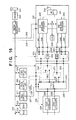
- Fig. 3 is a block diagram showing in detail a construction of the PHS engine unit 237.
- reference numerals 301 and 306 are switches for performing connection among a signal line connected to the analogue switch 217, a signal line connected to ISDN and a signal line for radio communication.
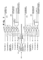
- Reference numeral 302 and 307 denote analogue/PCM converters; 303 and 308, ADPCM/PCM converters; 304 and 309, time-division-multiple-access (TDMA) assembling/disassembling portion for assembling/disassembling radio transmission frames shown in Fig. 7; and 305 and 310, ⁇ /4 shift QPSK modulator/demodulator.
- Reference numeral 311 denotes a multiplexer for selecting a baseband processor to be used in radio data communication. Note that as will be described later in the second embodiment, the multiplexer is not necessary when radio data communication is performed in two channels.
- switches 301 and 306 are switched by the control of CPU 238 in order to switch the data transmission path in various ways according to the situation. For instance, when communication is to be performed using a handset via the ISDN line, an analogue signal 245 outputted by the analogue switch 217 is converted to PCM codes by the analogue/PCM converter 302 and outputted to the data line 247. Meanwhile, when communication is performed between the handset and wireless telephone unit, audio data converted to PCM codes is converted to ADPCM codes by the ADPCM/PCM converter, assembled into a wireless frame, then modulated, and transmitted to a wireless line. Further, in a case where the audio data from the wireless telephone unit is sent to ISDN, the data line 247 is connected to the ADPCM/PCM converter 303.
- Reference numeral 312 denotes a phase comparator which outputs a pulse having a width corresponding to a phase difference.
- Reference numeral 313 denotes a low pass filter; 314, a temperature compensating voltage control oscillator (TVCXO); and 315, a divider. These portions enable to generate 19.2 MHz clock signal 316, having precision of ⁇ 5 ppm, which is synchronous with a 64 KHz clock signal extracted from ISDN.
- the baseband processors 239 and 240 operate with the generated 19.2 MHz clock signal as a reference.
- the ISDN line and PHS wireless line must operate in synchronization to prevent data overrun or underrun.
- the synchronization timing in the PHS wireless line requires high precision, i.e., within ⁇ 5 ppm. Since synchronization timing clock extracted from ISDN is not as precise as ⁇ 5 ppm, there is a necessity that a PLL (Phase-Locked Loop), constituted with the comparator 312 to divider 315, generates a 19.2 MHz clock signal, i.e., multiplication of the 64 KHz clock signal 260 synchronizing with ISDN, to operate the baseband processors 239 and 240.
- a PLL Phase-Locked Loop
- An output frequency of the TVCXO 314 is within 19.2 MHz ⁇ 5 ppm regardless of an input voltage.
- a 64 KHz clock signal, into which the output clock is divided, and a 64 KHz clock signal synchronizing with ISDN are inputted to the phase comparator 312.
- the phase comparator 312 if the phase of ISDN clock signal is leading, a 5V-pulse is outputted, while if the phase is lagging, a 0V-pulse is outputted, and a signal smoothed by the low pass filter 313 controls the TVCXO 314.
- Figs. 4 and 5 are logic diagrams showing detailed configuration of the switch 230.
- reference numerals 401 and 402 denote a decoder; 403 and 405, OR gates; and 404 and 406, AND gates.
- Fig. 4 shows a logic diagram for connecting the data line, connected to the channel B1 and channel B2 of the ISDN, with one of the HDLC controller 227, PIAFS controller 228, or the three signal lines connected to the PHS engine unit.
- the decoder 402 decodes the value and outputs L (0V) only to the OR gate 403 connected to the targeted destination among those destinations (252, 253, 254, 256, 257) connectable to the data lines 258 or 259, while outputs H (5V) to other OR gates. Therefore, the AND gate 404 receives data from the data lines 258 and 259 only from the selected OR gate; as a result, the data lines 258 and 259 are respectively connected to one line of the five output data lines.
- Fig. 5 is a logic diagram for connecting one of the HDLC controller 227, PIAFS controller 228, or the three signal lines connected to the PHS engine, with a transmission data line for channel B1 or B2 of the ISDN.
- the decoder 402 When the MPU 201 writes a predetermined value in the address allocated to the switch, the decoder 402 outputs L (0V) only to the OR gate 405, whose signal lines are connected to the data lines 258 and 259, among the data lines 252, 253, 254, 256 and 257. Accordingly, one of the five signal lines is connected to the data line 258, and the other line is connected to the data line 259.
- Fig. 6 is a logic diagram showing detailed configuration of the port switch 233.
- reference numeral 501 denotes a decoder for generating signals for controlling the selection circuits 505 and 509; and 502, a serial/parallel converter for converting serial data transmitted by the port switch 229 into parallel data.
- the serial/parallel converter performs parallel conversion operation in synchronization with the 8 KHz and 64 KHz clock signals extracted from the ISDN.
- Reference numeral 503 denotes a FIFO buffer for buffering data on which serial/parallel conversion has been performed.
- Reference numeral 504 denotes a parallel/serial converter for converting the parallel signal, outputted by the FIFO buffer, into serial data.
- the parallel/serial converter performs the conversion operation in synchronization with the 8 KHz or 64 KHz clock signals supplied by the PHS engine unit 237.
- the FIFO buffer 503 serves to prevent data error due to a phase difference between the clock of the ISDN side and clock of the PHS side. More specifically, even if the data-latch timing of the parallel/serial converter 504 coincides with the timing at which output data of the serial/parallel converter 502 changes, the FIFO buffer 503 buffers data for two bytes in order to prevent data error.
- Reference numeral 505 denotes a selection circuit for selecting whether serial data is to be converted to an analogue signal or to be outputted by radio.
- the selection circuit 505 is controlled by the MPU 201 via the decoder 501. An output from the selection circuit 505 is inputted to the PHS engine unit 237.
- data from the PHS engine unit 237 is outputted to the port switch 229 via the multiplexer 509, serial/parallel converter 508, FIFO buffer 507 and parallel/serial converter 506.
- Reference numerals 510-515 basically perform the same operation as the numerals 502-504 and 506-508. Note that the parallel/serial converter 512 and serial/parallel converter 515 operate at 8 KHz and 32 KHz clock timing respectively, for performing speed conversion between 32 Kbps and 64 Kbps.
- Fig. 7 is a block diagram showing a detailed configuration of the analogue switch 217.
- reference numeral 601 denotes a register for controlling an analogue switch, in which the MPU 201 writes data via data bus.
- Reference numeral 602 denotes a decoder for converting data written in the register 601 and generating signals for controlling the analogue switches 603-614 and port switches 615 and 616.
- Reference numerals 603-614 denote analogue switch devices, constituted by an input pin, an output pin and a control pin. When the control pin is at low level, the input pin and output pin are connected; while when the control pin is at high level, the input pin and output pin are disconnected.
- Reference numeral 616 denotes a port switch for controlling whether to connect the baseband processors 239 and 240, melody sound source 216 and recorded communication output unit 213 to be connected to the handset or to the speaker.
- the analogue switch selects the data to be transmitted to the baseband processors 239 and 240, from the output signal of the modem 213, audio signal inputted from the handset 214 or melody sound source 216, based on the control of MPU 201. More specifically, when FAX communication is performed, the modem 213 is connected; when communication is performed via the handset, the handset 214 is connected; and when the line is on hold, the melody sound source 216 is connected.
- data outputted by the baseband processors 239 and 240 is inputted to the modem 213.
- a signal outputted by the holding melody generator 216 is outputted to the handset 214 or speaker 215.
- a signal outputted by the modem 212 is sent to the handset 214 or speaker 215.
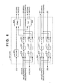
- Figs. 8A to 8C are diagrams showing frame formats for PHS radio transmission.
- Fig. 8A shows an SCCH (Signalling Control Channel) frame used when wireless link is established;
- Fig. 8B a PCH (Paging Channel) frame;
- Fig. 8C a frame, such as TCH or FACCH, used for normal data communication.
- SCCH Signal Control Channel
- Fig. 8B a PCH (Paging Channel) frame
- Fig. 8C a frame, such as TCH or FACCH, used for normal data communication.
- Figs. 9A-9D are diagrams showing frame formats used in radio-data-transmissionprotocol (PIAFS).
- Fig. 9A shows a negotiation frame transmitted/received to select a protocol and establish frame synchronization
- Fig. 9B a synchronization frame transmitted/received to establish frame re-synchronization during communication
- Fig. 9C a control frame for transmitting/receiving control data
- Fig. 9D a data frame for transmitting/receiving user data.
- the negotiation frame is used for in-band negotiation, frame synchronization is established, and the response delay time is clocked; next, communication parameters are set by the control frame; and finally, data communication using the data frame is started.
- Fig. 10 is a diagram showing a frame format according to the PPP (Point to Point Protocol).
- the flag is a pattern 01111110 indicating the beginning and end of the frame; address is a fixed pattern 11111111; control is a fixed pattern 00000011; protocol is two-byte data indicating the type of protocol used in the network layer; data is variable-length transmission data including PPP control data, user data and the like; and FCS is data error detection codes.
- Fig. 11 is a flowchart describing audio data communication operation executed by a PHS telephone unit, and PIAFS communication operation executed by a wireless data terminal (PC).
- PC wireless data terminal
- Fig. 12 is a flowchart describing data communication operation executed by a PC connected by a cable.
- Fig. 13 is a flowchart describing synchronous PPP data communication operation executed by a wireless PC.
- Programs for executing the processing shown in Figs. 11, 12 and 13 are stored in a program memory having application programs of the data terminal, a ROM incorporated in the CPU 238 and the ROM 203, as a program executed by a computer (or a microcomputer) necessary for the respective processing.
- Figs. 14 and 15 are flowcharts showing communication sequences at the time of data transmission/reception in a radio communication apparatus including a wireless telephone unit and a wireless data terminal.
- the PHS telephone unit 102 first transmits a link-channel-establish request for a wireless link to the radio communication apparatus 101 using SCCH channel.
- the CPU 238 of the PHS engine unit 237 receives the wireless link-channel-establishrequest through the antenna 242, radio-frequency (RF) unit 241 and baseband processor 239 (S1001), a link-channel-allocation message is transmitted to the PHS telephone unit 102.
- RF radio-frequency
- the PHS telephone unit 102 Upon receiving the link-channel-allocation message from the radio communication apparatus 101 via SCCH, the PHS telephone unit 102 transmits a call-setting message.
- the CPU 238 which has received the call-setting message transmits a call-setting-confirmationmessage to the PHS telephone unit 102.
- the PHS telephone unit 102 which has received the call-setting-confirmationmessage, exchanges messages related to radio control and motion control with the CPU 238, and transmits an additional data message.
- the CPU 238 Upon receiving the additional data message, the CPU 238 notifies the MPU 201 through the serial communication port 244, that there has been an outgoing-call request to ISDN (S1002).
- the MPU 201 which has received the outgoing-call request, starts transmission processing of the ISDN interface unit 225 (S1003).
- the ISDN interface unit 225 transfers, by direct memory access (DMA), a layer 3 message stored by the MPU 201 in the memory 204, and exchanges messages with the ISDN (S1004).
- DMA direct memory access
- the ISDN interface unit 225 Upon receiving a response message from the ISDN (S1005), the ISDN interface unit 225 outputs an interruption request to the MPU 201.
- the MPU 201 which has received the interruption request, recognizes a response from the called party, the MPU 201 notifies the response to the CPU 238. Then, the CPU 238 transmits a response message to the PHS telephone unit 102 through the baseband processor 239 and the like (S1006). Accordingly, a communication channel is established between the PHS telephone unit 102 and radio communication apparatus 101.
- the MPU 201 switches the port switch so as to connect the communication channel of the PHS telephone unit 102 with the channel B of the ISDN.
- the switch 234 of the port switch 233 is controlled to connect the data line 247 with the data line 252.
- the port switch 229 is switched so that the data line 252, to which switch 234 is connected, is connected to the data line 258 at the channel B1 of the ISDN (S1008).
- the MPU 201 sets the port switch 229 to start echo cancel operation of the echo canceller 226 (S1009).
- audio data inputted by the PHS telephone unit 102 is received by the PHS baseband processor 239, and the received PCM data is transmitted to the ISDN through the echo canceller 226, ISDN interface unit 225, DSU 223 and connector 222. Audio data received from the ISDN is transmitted to the PHS telephone unit 102 through the same path.
- the PC 103 When the PC 103 performs data communication with a device connected to the ISDN, communication application software for the PC 103 is started, and the outgoing-call number is transmitted with AT command.
- the radio communication apparatus upon receiving the command (S1101), the data is inputted to the serial communication controller 219 via the RS232C connector 221.
- the serial communication controller 219 which has received the data, outputs an interruption request to the MPU 201 (S1102), and the MPU 201 transfers the data stored in the serial communication controller to the memory 204 (S1103).
- the MPU 201 which has analyzed the received data, recognizes that the received data is an outgoing-call request, the MPU 201 starts transmission processing of the ISDN interface unit 225 (S1104).
- the ISDN interface unit 225 transfers, by direct memory access (DMA), a layer 3 message stored by the MPU 201 in the memory 204, and exchanges messages with the ISDN (S1105).
- DMA direct memory access
- the ISDN interface unit 225 Upon receiving a response message from the ISDN, the ISDN interface unit 225 outputs an interruption request to the MPU 201.
- the MPU 201 which has received the interruption request, recognizes connection with the called party, the MPU 201 notifies the connection to the PC 103 via the serial communication controller 219 (S1107).
- the MPU 201 controls the port switch 229 to connect the data line 257 with the data line 258 (S1108).
- data outputted by the HDLC controller 227 is transmitted to the ISDN through the echo canceller 226, ISDN interface unit 225, DSU 223 and connector 222.
- the MPU 201 sets the echo canceller 226 in the through mode by using the port switch 229 (S1109).
- the data communication channel is established, and data transmission/reception is enabled between the PC 103 and ISDN (S1110).
- the PC 103 which has received the connection notification, starts the subsequent data transmission.
- the data to be transmitted has a frame configuration according to the asynchronous PPP (Point to Point Protocol) shown in Fig. 10.
- the data transmitted by the PC 103 is stored in the memory 204 via the serial communication controller 219 as similar to the aforementioned AT command data. More specifically, upon receiving data (S1111), the serial communication controller 219 outputs an interruption request to the MPU 201 (S1112), and the MPU 201 transfers the data to the memory 204 (S1113). Since the stored data has a frame configuration according to the asynchronous PPP, there is a case where the data includes a pattern same as the flag pattern (01111110) of HDLC used for ISDN transmission. To cope with this situation, the MPU 201 reads the stored data and performs PPP asynchronization-synchronizatbn conversion processing so that the above flag pattern does not appear in the data (S1114). More specifically, when a bit array the same as the flag pattern appears, processing is performed to replace the flag pattern with the control escape (01111101) + data (01011110) reversing the sixth bit of the flag pattern.
- the MPU 201 transfers data other than the flag pattern to the HDLC controller 227 (S1115).
- the HDLC controller 227 transfers the data 255, which is in synchronous with the 64 KHz clock signal extracted from the ISDN, to the port switch 229, and the data is transmitted to the ISDN through the ISDN interface unit 225 (S1116).
- PC 103 can perform data communication via ISDN.
- a response message is transmitted to the PHS telephone unit 104 (S1006), and the PHS telephone unit 104 notifies the PC 106 via the PIAFS card 105 that the destination terminal has responded.
- the radio communication apparatus 101 determines that the transmission data is PIAFS data since the data element included in the call-setting message is set to unlimited digital data having 32 Kbps, and switches the switch 230 and switch 231 of the port switch 229. More specifically, the switch 231 is switched such that the data line 251 is connected to the data line 252 through the I.460 data conversion processor 236, and the switch 230 is switched such that the data line 252 is connected to the data line 258 (S1011). Further, the echo canceller 226 is set in the through mode (S1012). In the above-described procedure, the data communication channel is established (S1013).
- the PC 106 and the destination terminal exchange negotiations for the PIAFS protocol.
- the PIAFS negotiation frame transmitted by the PIAFS card 105 is received by the PHS baseband processor 239 of the radio communication apparatus 101 via the PHS telephone unit 104.
- the received 32 Kbps data is sent to the I.460 data conversion processor 236 via the data line 251 to be converted to 64 Kbps, and transmitted to the ISDN through port switch 229, echo canceller 226, ISDN interface unit 225 and DSU 223.
- the PIAFS card 105 adds a PIAFS header and trailer to the data (PPP protocol format) transmitted by the PC 106, and the data is transmitted to the destination terminal in the same flow as the aforementioned negotiation frame.
- the PIAFS header and trailer are deleted, and only the data in the PPP protocol format, stored in the data field, is extracted and processed by upper-layer software.
- the MPU 201 starts transmission processing of the ISDN interface (S1203), and transmits a call-setting message to ISDN (S1204). Note that in this case, since synchronous PPP data having 64 Kbps is transmitted, the data element included in the call-setting message is set to unlimited digital data having 64 Kbps.
- a response message is transmitted to the PHS telephone unit 104 (S1206), and the PHS telephone unit 104 notifies the PC 106 via the PIAFS card 105 that the destination device has responded. As a result, a communication channel is established.
- the radio communication apparatus 101 switches the switch 230 and switch 231 of the port switch 229 in order to transmit the received PIAFS data to the ISDN as synchronous PPP data. More specifically, the switch 231 is switched such that the signal on the data line 251 is transmitted to a 32 Kbps PIAFS data interface unit of the PIAFS controller 228 through the 1.460 data conversion processor 236 and data line 255, and the switch 230 is switched such that a 64 Kbps data interface unit of the HDLC controller 227 is connected to the data line 258 through the data line 257 and switch 230 (S1207).
- the echo canceller 226 is set in the through mode (S1208).
- the I.460 data conversion processor 236 is also set in the through mode for not performing conversion processing (S1209).
- the PC 106 and the PIAFS controller 228 of the radio communication apparatus 101 negotiates the PIAFS protocol.
- a communication-parameter-settingrequest frame, transmitted by the PIAFS card 105, is received by the PHS baseband processor 239 of the radio communication apparatus 101 via the PHS telephone unit 104 (S1210).
- the received 32 Kbps data is inputted to the I.460 data conversion processor 236 via the data line 251. Since the I.460 data conversion processor is set in the through mode, data is inputted to the port switch 229 without conversion.
- the data inputted to the port switch 229 is inputted to the PIAFS controller 228 via the switch 231.
- the PIAFS controller transmits a communication-parameter-settingreception frame to the PC 106 via the PHS engine unit 237 (S1211), and upon predetermined negotiation steps, a radio-data-transmission link (PIAFS link) is established (S1212).
- PIAFS link a radio-data-transmission link
- the PC 106 starts data transmission to the ISDN. More specifically, the PIAFS card 105 adds a PIAFS header and trailer to the PPP-format data transmitted by the PC 106, and the data is inputted to the PIAFS controller 228 in the similar manner to the aforementioned negotiation frame.
- the MPU 201 writes the data stored in the memory 204 into the HDLC controller 227 (S1215), and the HDLC controller 227 outputs the data in synchronization with 64 KHz timing of ISDN.
- the outputted data is transmitted to the ISDN through the switch 230, echo canceller 226, ISDN interface unit 225 and DSU 223 (S1216).
- the HDLC controller 227 detects a flag pattern in the received data (S1218), the controller outputs an interruption request to the MPU 201, and the MPU 201 stores the received data in the memory 204 (S1219).
- the MPU 201 performs PPP synchronization-asynchronization conversion processing on the stored data (S1220), and transmits the data to the PC 106 via the PHS engine unit 237 after adding a header and trailer by the PIAFS controller 228 (S1221).
- a 9600 bps analogue signal modulated by the FAX modem 213 is inputted to the analogue switch 217, outputted to the PHS engine unit 237, and coded to PCM data by the CODEC of the PHS baseband processor 239 or 240.
- the analogue switch 217 is switched so as to use either the PHS baseband processor 239 or 240 which is not in use. For instance, when the PHS baseband processor 239 is not used, the signal outputted by the FAX modem 213 is inputted to the PHS baseband processor 239 via the data line 245, and the data converted to PCM codes by the PHS baseband processor 239 is outputted to the port switch 233 via the data line 247.
- the port switches 233 and 229 are switched such that the data line 247 is connected to the data line 258.
- the data is transmitted to the ISDN through the echo canceller 226, ISDN interface unit 225 and DSU 223. Note that the echo canceller 226 is set in the through mode.
- the analogue signal modulated by the FAX modem 213 is transmitted via an analogue line without conversion.
- the CPU used in the configuration of the present embodiment is independent from the facsimile processing for the wireless line controller and ISDN control, the conventional facsimile unit can be used without greatly changing its design.
- the command which has been exchanged between the conventional facsimile unit and a data terminal via a parallel interface unit can be adopted by a data terminal which performs communication via a PHS telephone unit.
- the data terminal 106 connected to the PHS is able to use the color printer 208 and color scanner 209 of the facsimile unit.
- the connection of the analogue switch 217 is changed from the above facsimile-communication setting, and the echo canceller 226 is set in the echo-cancel mode.
- the data flow is the same as that in the case of facsimile communication.
- the data stored in the memory 204 is written in the shared register 218 by the MPU 101.
- the shared register outputs an interruption request to the CPU 206 of the FAX engine unit 205, and the CPU 206 which has received the interruption request transfers the data in the shared register to the printer 208 where printing is performed.
- the 5 to 2 switch 230 is replaced by a 7 to 2 switch 1401; and a PIAFS controller 1402, a switch 1403 and an I.460 processor 1404 are added. Accordingly, PIAFS processing is performed in correspondence with the PHS baseband processors 239 and 240 respectively, realizing radio data communication by two channels.
- the PHS Personal Handy-phone System
- PIAFS Radio-data-transmission protocol
- the handset 214, speaker 215 and holding melody generator 216 shown in Fig. 2 are controlled by the CPU 206 of the FAX engine unit 205.
- the FAX modem 213 may be controlled by the CPU 206
- the handset 214, speaker 215 and holding melody generator 216 may be controlled by the MPU 201.
- control operation of each of the units can be realized by a plurality of microcomputers (MPU 201, CPU 206, CPU 238) which interactively operate respective control programs for executing the above-described various communication operation.
- the MPU 201 performs ISDN calling control, controls the serial interface unit which exchanges data with PC, controls each data path for audio data communication, data communication and FAX communication, and manages resources thereof.
- the CPU 206 controls peripheral devices of the FAX engine unit (color printer 208, color scanner 209, operation panel 210 and FAX modem 213) and manages the resources thereof.
- the CPU 238 controls the PHS baseband processors 239 and 240 and RF unit in the PHS engine unit 237, and manages the resources thereof.
- control programs for executing the control operation described below are stored in ROMs of the MPU 201, CPU 206 and CPU 238.
- Fig. 22 is a flowchart describing control operation of the system initialization.
- the MPU 201 When the power of the apparatus is turned on (S2001), the MPU 201 first starts-up each device (start-up each device), then sends an initialization command to the CPU 206 (S2002) and further sends an initialization command to the CPU 238 (S2003). To the CPU 206, the command is transmitted via the serial communication port 243, while to the CPU 238, the command is transmitted via the serial communication port 244.
- Fig. 23 is a flowchart describing control operation of receiving signals from the CPU 206 of the MPU 201.
- the switch 233 is switched so as to establish a path in the switch 234 by connecting the PCM data line 247 with the data line 252, and establish a path in the switch 230 by connecting the port 252 with the port 258 (S2107).
- a command is outputted to the CPU 238 via the serial communication port 244 so as to establish a path in the PHS baseband processor 239 by connecting the analogue signal line 245 with the PCM data line 247 (S2108).
- a command indicative of connection completion is outputted to the CPU 206 via the serial communication port 243 (S2109).
- the MPU 201 determines whether the command is addressed to an extension slave unit or an external line. Then, data of the shared register 218' is read out to determine whether or not the ISDN line or PHS wireless line is available (S2112 and S2113). If one of the line is available, the telephone communication is assigned to the available line, and status data indicative of telephone communication is written in the shared register 218 in correspondence with the respective communication paths (S2114). In a case where the command is addressed to an external line (S2115), control for line connection is executed by using the ISDN I/F unit 225 (S2116).
- a path is established in the analogue switch 217 by connecting the handset 214 with the analogue signal line 245. Then, the switch 233 is switched so as to establish a path in the switch 234 by connecting the PCM data line 247 with the data line 252, and establish a path in the switch 230 by connecting the port 252 with the port 258 (S2117). Further, a command is outputted to the CPU 238 via the serial communication port 244 so as to establish a path in the PHS baseband processor 239 by connecting the analogue signal line 245 with the PCM data line 247 (S2118). Then, a command indicative of connection completion is outputted to the CPU 206 via the serial communication port 243 (S2119).
- a wireless connection command is outputted to the CPU 238 via the serial communication port 244 (S2120).
- a command indicative of connection completion via the first channel is returned by the CPU 238 (S2121)
- a path is established in the analogue switch 217, by connecting the handset 214 with the analogue signal line 245 (S2122).
- the MPU 201 instructs the CPU 238 by sending a command via the serial communication port 244, so as to establish a path in the PHS baseband processor 239 by connecting the analogue signal line 245 with the RF unit 241 (S2123), and returns a command indicative of connection completion to the CPU 206 (S2124).
- Fig. 24 is a flowchart showing control operation of data communication performed by a data processing terminal (e.g., personal computer) connected via a wired interface unit.
- a data processing terminal e.g., personal computer
- the radio communication apparatus is capable of data transmission/reception with the personal computer (PC) through the RS232C connector 221.
- data from the PC is stored in the SRAM 204 via an RS232C controller, and analyzed by the MPU 201.
- AT command is used as the control command. Therefore, if the data transmitted by the PC is an AT command, it is recognized as control data; while if the data other than AT command is transmitted, the data is recognized as real data.
- the MPU 201 When a control command for data transmission request is transmitted by the PC through the RS232C controller 219 (S2201), the MPU 201 reads out data of the shared register 218 to determine whether or not the ISDN line is available (S2202). If the line is not available, a connection-failure command is outputted to the PC via the RS232C controller 219. If the line is available, the communication is assigned to the available line, and the status data indicating that the ISDN line is performing data communication, is written in the shared register 218 (S2203). Then, control for line connection is executed by using the ISDN I/F unit 225 (S2204).
- channel B1 is connected (S2205)
- the port 257 is connected with the port 258 in the switch 230 (S2206), and a control command indicative of connection completion is outputted to the PC through the RS232C controller 219 (S2207).
- Real data sent by the PC which has been stored in the SRAM 204 through the RS232C controller 219 (S2208) is temporarily stored in the SRAM 204 (S2209), and the data stored in the SRAM 204 is written in the HDLC controller 227 (S2210) and outputted to the ISDN line (S2211).
- the data received from the ISDN line S2212
- the data received from the ISDN line is temporarily stored in the SRAM 204 (S2213) and outputted to the PC through the RS232C controller 219 (S2214).
- Fig. 25 is a flowchart showing control operation of the MPU 201 when receiving signals from the CPU 238.
- the MPU 201 When a reception command is received from the CPU 238 through the serial communication port 244 (S2301), the MPU 201 analyzes whether the command is for telephone communication or for data communication, and if the command is for telephone communication (S2302), the MPU 201 determines whether the command from CPU is addressed to a master unit or an external unit (S2303).
- S2304 If the command is addressed to a master unit, status data of the shared register 218 is read (S2304). If the handset of the master unit is available (S2305), the telephone communication is assigned to the available handset and the status of the master unit handset is set to a busy state in the shared register 218 (S2306). Then, a path is established in the analogue switch 217 by connecting the handset 214 with the analogue signal line 245 (S2307).
- the MPU 201 instructs the CPU 238 by sending a command via the serial communication port 244, so as to establish a path in the PHS baseband processor 239 by connecting the analogue signal line 245 with the RF unit 241 (S2308), and returns a command indicative of connection completion to the CPU 238 (S2309).
- status data of the shared register 218 is read (S2311). If the ISDN line is available (S2312), the communication is assigned to the available ISDN line and the status of the ISDN line is set to the communication state in the shared register 218 (S2313). Then, connection is established with the ISDN line (S2314).
- the switch 234 in the switch 233 is connected to the analogue signal line 247, and the port 258 of the switch 229 is connected to the port 252 (S2315).
- the MPU 201 instructs the CPU 238 by sending a command via the serial communication port 244, so as to establish a path in the PHS baseband processor 239 by connecting the analogue signal line 245 with the RF unit 241 (S2316), and returns a command indicative of connection completion to the CPU 238 (S2317).
- S2318 In a case of data communication (S2318), status data of the shared register 218 is read (S2319). If the ISDN line is available (S2320), the data communication is assigned to the available ISDN line and the ISDN line status is set to the communication state in the shared register 218 (S2321). Then, connection is established with the ISDN line (S2322). In a case where PIAFS data transmitted by the PHS telephone unit is outputted to the ISDN line without conversion, the data is outputted to the port 254 of the switch 231, and the port 254 of the switch 230 is connected to the port 258 (S2323).
- the MPU 201 instructs the CPU 238 by sending a command via the serial communication port 244, so as to establish a path in the PHS baseband processor 239 by connecting the 32 Kbps data communication line 251 with the RF unit 241 (S2324), and returns a command indicative of connection completion to the CPU 238 (S2325).
- data transmitted from the PHS unit at 32 Kbps is converted to 64 Kbps by the I.460 data conversion processor 236 and transmitted to the ISDN.
- the PIAFS data transmitted by the PHS telephone unit is outputted to the ISDN after being converted to PPP data
- the data is outputted to the port 255 of the switch 231, and the port 257 of the switch 230 is connected to the port 258 (S2323).
- the MPU 201 instructs the CPU 238 by sending a command via the serial communication port 244, so as to establish a path in the PHS baseband processor 239 by connecting the 32 Kbps data communication line 251 with the RF unit 241 (S2324), and returns a command indicative of connection completion to the CPU 238 (S2325).
- PIAFS data transmitted by the PHS telephone unit is temporarily stored in the SRAM 204 as PPP data through the PIAFS controller 228, and transmitted to the line through the HDLC controller 227.
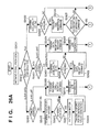
- Figs. 26A and 26B are flowcharts showing control operation of incoming signals from ISDN.
- the MPU 201 analyzes the contents of the incoming signal (S2402).
- an address is checked (S2403). If there is no particular designation, e.g., addressed to a master unit or slave unit, the shared register is read to confirm whether or not the handset of the master unit is used (S2405). If it is not used (S2406), the MPU 201 establishes a path in the analogue switch 217 by connecting the speaker 215 with the analogue signal line 245 (S2407). Then, the MPU 201 outputs an incoming-call-sound-generation-request command to the CPU 238 via the serial communication port 244 (S2408).
- the CPU 238 Upon receiving the incoming-call-sound-generation-request command, the CPU 238 generates an incoming-call sound by using a sound source in the PHS baseband processor and outputs the sound to the analogue signal line 245. Further, the MPU 201 outputs an incoming-call-request command to the CPU 238 via the serial communication port 244 (S2409).
- the CPU 238 begins establishing a wireless-link by using the PHS baseband processor 239 and RF unit 241 (S2410). Upon off-hook of the handset of the master unit (S2411), the MPU 201 outputs a command to the CPU 238 via the serial communication port 244 to stop the incoming-call-sound (S2412).
- the MPU 201 returns a response to the ISDN (S2413) and establishes connection with the ISDN. Then, the status of the handset is set in the busy state in the shared register (S2414). For instance, when the channel B1 is connected, the MPU 201 establishes a path in the analogue switch 217 by connecting the handset 214 with the analogue signal line 245, and establishes a path in the switch 230 by connecting the port 258 with the port 252. Then, the port 252 is connected to the PCM data line 247 using the switch 234 (S2415).
- the MPU 201 instructs the CPU 238 by sending a command via the serial communication port 244, so as to establish a path in the PHS baseband processor 239 by connecting the PCM data line 247 with the analogue signal line 245 (S2416). Then, the MPU 201 sends a PHS disconnect command to the CPU 238 via the serial communication port 244 (S2417).
- the CPU 238 sends the MPU 201 a response command via the serial communication port 244.
- the MPU 201 outputs a command to the CPU 238 via the serial communication port 244 to stop the incoming-call-sound (S2418). Further, the MPU 201 returns a response to the ISDN (S2419) and establishes ISDN connection.
- the MPU 201 establishes a path in the analogue switch 217 by connecting the handset 214 with the analogue signal line 245, and establishes a path in the switch 230 by connecting the port 258 with the port 252.
- the port 252 is connected to the PCM data line 247 using the switch 234 (S2420).
- the MPU 201 instructs the CPU 238 by sending a command via the serial communication port 244, so as to establish a path in the PHS baseband processor 239 by connecting the PCM data line 247 with the RF unit 241 (S2421).
- the MPU 201 In a case of receiving a FAX signal, the MPU 201 reads the shared register 218, to confirm the status of a peripheral device for FAX reception (S2422). If the peripheral device is available (S2423), the MPU 201 sends a FAX reception command to the CPU 206 via the serial communication port 243 (S2424). When the MPU 201 receives a FAX-reception-confirmation command from the CPU 206 through the serial communication port 243 (S2425), the MPU 201 writes FAX reception status in the shared register 218 (S2426), returns a response to the ISDN side and establishes connection with the ISDN (S2427).
- the MPU 201 when the channel B1 is connected, the MPU 201 establishes a path in the analogue switch 217 by connecting the FAX modem 213 with the analogue signal 245, and establishes a path in the switch 230 by connecting the port 258 with the port 252. Then, the port 252 is connected to the PCM data line 247 using the switch 234 (S2428). Further, the MPU 201 instructs the CPU 238 by sending a command via the serial communication port 244, so as to establish a path in the PHS baseband processor 239 by connecting the PCM data line 247 with the analogue signal line 245 (S2429).
- an address is checked (S2430). If there is no particular designation, e.g., addressed to a master unit or slave unit, the shared register is read to confirm whether or not the PC connected to the master unit is available (S2431). If it is available (S2432), the MPU 201 outputs a data reception command to the PC via the RS232C controller (S2433). Then, the MPU 201 outputs a data-reception-request command to the CPU 238 via the serial communication port 244 (S2434). The CPU 238 begins establishing a wireless-link by using the PHS baseband processor 239 and RF unit 241 (S2435).
- the MPU 201 When a response is returned from the PC connected to the master unit (S2436), the MPU 201 returns a response to the ISDN and establishes connection with the ISDN (S2437). Then, the status of the PC is set in the used state in the shared register (S2438). For instance, when the channel B1 is connected, the MPU 201 connects the port 258 with the port 257 using the switch 230 (S2439). Then, the MPU 201 sends a PHS disconnect command to the CPU 238 via the serial communication port 244 (S2440). The received data is temporarily stored in the SRAM 204 via the HDLC controller 227. The MPU 201 transmits the stored data to the PC via the RS232C controller 219 (S2441).
- the CPU 238 sends a response command to the MPU 201 via the serial communication port 244.
- the MPU 201 outputs a data-reception-halt command to the PC via the RS232C controller 219 (S2442). Further, the MPU 201 sends a response to the ISDN side and establishes connection with the ISDN (S2443). For instance, when the channel B1 is connected and the data is PPP data, the port 258 is connected with the port 257 using the switch 231. Then, the port 257 is connected with the port 255 using the switch 231 (S2444).
- the MPU 201 instructs the CPU 238 by sending a command via the serial communication port 244, so as to establish a path in the PHS baseband processor 239 by connecting the 32 Kbps data communication line 251 with the RF unit 241 (S2445).
- the received data is temporarily stored in the SRAM 204 via the HDLC controller.
- the MPU 201 transmits the stored data to the PIAFS controller 228 and further to the I.460 data conversion processor 236 where speed conversion is performed, and outputs the converted data to the PHS engine unit 237. If the data is PIAFS data, the port 258 is connected with the port 254 using the switch 230, then further connected to the port 254 by the switch 231 (S2444).
- the MPU 201 instructs the CPU 238 by sending a command via the serial communication port 244, so as to establish a path in the PHS baseband processor 239 by connecting the 32 Kbps data communication line 251 with the RF unit 241 (S2445).
- the MPU 201 transmits the received data to the PIAFS controller 228 and further to the I.460 data conversion processor 236, where speed conversion is performed, and outputs the converted data to the PHS engine unit 237.
- Fig. 27 is a flowchart describing communication control operation of the CPU 206.
- the command is analyzed (S2502) and operation of respective peripheral device is started.
- the command is sent to the MPU 201 via the serial communication port 243.
- the status of the peripheral device whose operation has started, is written in the shared register 218.
- a FAX transmission command is sent by the PC via the operation panel or the parallel communication interface port 211 (S2503)
- a FAX-start command (S2504) and a telephone number (S2505) are sent to the MPU 201 via the serial communication port 243.
- the statuses of color scanner and FAX modem are set in the used state in the shared register (S2507).
- the color scanner 209 is operated to read the data (S2508), the read data is coded by using the FAX modem (S2509) and the data is sent to the analogue switch 217 (S2510).
- the statuses of color printer and FAX modem are set in the used state in the shared register (S2511), and a FAX-reception-confirmation command is sent to the MPU 201 via the serial communication port 243 (S2512).
- the data is decoded by using the FAX modem 213 (S2514) and printed out by the color printer 208 (S2515).
- Fig. 28 is a flowchart describing control operation of the CPU 238.
- the CPU 238 when the CPU 238 receives a signal through the PHS baseband processors 239 and 240 (S2601), the CPU 238 retrieves a radio communication channel resource (S2602). If the radio communication channel resource is available (S2603), wireless link is established (S2604). When the wireless link is established and call-setting control data is transmitted by a wireless slave unit (S2605), the CPU 238 sends a call-setting command to the MPU 201 via the serial communication port 244 (S2606). Upon receiving a call-setting-reception command, call command and response command from the MPU 201 via the serial communication port 244, the CPU 238 generates respective control data and sends them to the wireless slave unit.
- the CPU 238 establishes radio communication by exchanging authentication data and the like (S2607). Then, the CPU 238 receives from the MPU 201 via the serial communication port 244, a command for setting the path of the PHS baseband processor (S2608). According to the command, the CPU 238 transmits the data, sent from the RF unit 241 (240) at 32 Kbps, to the path 248 (250) where data is expanded and outputted at 64 Kbps, or to the path 251 where data is outputted at 32 Kbps, or to the analogue signal path 245 (S2609). Then, data communication is started (S2610).
- the CPU 238 When disconnection-control data is transmitted by the wireless slave unit (S2611), the CPU 238 sends a disconnect command to the MPU 201 via the serial communication port 244 (S2612). Then the wireless link is disconnected.
- the CPU 238 When the CPU 238 receives a connection command from the MPU 201 via the serial communication port 244, the CPU 238 confirms an availability of a radio communication channel (S2614), and if it is available, establishes a wireless link (S2615). Upon receiving response data from the wireless slave unit (S2616), the CPU 238 transmits a response command to the MPU 201 via the serial communication port 244 (S2617). Further, the CPU 238 receives from the MPU 201 via the serial communication port 244, a command for setting a path of the PHS baseband processor (S2618).
- the CPU 238 transmits the data, sent from the RF unit 241 (240) at 32 Kbps, to the path 248 (250) where data is expanded and outputted at 64 Kbps, or to the path 251 where data is outputted at 32 Kbps, or to the analogue signal path 245 (S2619). Then, data communication is started (S2620).
- the CPU 238 When the CPU 238 receives a disconnect command from the MPU 201 via the serial communication port 244 (S2621), the CPU 238 disconnects the wireless link (S2612).
- the CPU 238 when a sound-generation command is transmitted by the MPU 201 via the serial communication port 244, the CPU 238 outputs the designated sound, using the sound source of the PHS baseband processor 239, to the designated path (analogue signal path 245, path 248 where data is outputted at 64 Kbps, or path from the RF unit 241).
- radio communication apparatus and communication system incorporate the functions of terminal adapter, facsimile printer, scanner and PHS master unit, it is possible to save the space and attain excellent cost-performance.
- communication is enabled by using an arbitrary unit selected from a wireless data terminal, data terminal connected via cable, wireless telephone unit, handset, facsimile or the like.
- the present invention can be realized without changing the circuit structure of the conventional facsimile.
- the terminal adapter has functions as a printer, scanner, facsimile and telephone unit which are integratedly controlled, the operability is improved, space is saved and cost is reduced.
- a data terminal PC or the like
- a wireless data terminal PAFS-compliance terminal
- a wireless telephone unit PHS telephone unit
- two channels of ISDN can be effectively utilized so as to enable data transmission while communicating with a wireless telephone unit.
- two, the data terminal (PC or the like) connected by cable, wireless data terminal and/or wireless telephone unit can be simultaneously connected to the ISDN.
- the communication system includes a data terminal and plural wireless telephone units
- two, the data terminal and/or plural wireless telephone units can be simultaneously connected to the ISDN.
- two, the data terminal, wireless telephone unit and/or handset belonging to the radio communication apparatus main body, can be simultaneously connected to the ISDN.
- data complying with the radio-data-transmissionprotocol can be transmitted to a destination which does not comply with the radio-data-transmissionprotocol.
- data transmitted by a wireless data terminal at 32 Kbps can be transmitted to the ISDN having transmission speed of 64 Kbps.
- a path optimized for each data communication can be selected.
- the communication system realizes facsimile function and efficiently utilizes each of the resources in the system.
- PCM conversion processing of wireless communication data and PCM conversion processing of analogue signals are performed by a common analogue/digital conversion processor. Therefore, the size and cost of the system can be reduced.
- line echo generated during communication can be removed, and data during data communication can be transmitted without a change.
- data can be transmitted/received in unit of byte, by adjusting timing of serial data having different phases.
- data error can be prevented even if there is a phase difference between a clock extracted from the digital public communication line and a clock of the digital radio communication controller.
- the digital public communication line and digital radio communication line can be operated in synchronization. Accordingly, data underrun and overrun can be prevented.
- the precision of the clock signal operating the digital wireless communication line are maintained within a predetermined precision range.
Abstract
Description
- The present invention relates to a radio communication apparatus, having combined functions as a terminal adapter, a digital radio communication apparatus, a facsimile communication apparatus and so on, for being connected to a digital public communication line.
- Lately, as the ISDN (Integrated Services Digital Network) is widely adopted, a data terminal such as a personal computer or the like is connected to ISDN via a terminal adapter for data communication.
- In this case, the data terminal (hereinafter referred to as PC) is connected to the terminal adapter by a cable, e.g., RS232C, and transmits data to the terminal adapter according to an asynchronous scheme at the transmission speed of, e.g., 2400 bps, 4800 bps, 9600 bps, 19.2 Kbps, 38.4 Kbps and so forth. The terminal adapter converts the transmission speed of the received data to 64 Kbps according to the CCITT (International Telegraph and Telephone Consultative Committee) Standard Recommendation V. 110, I. 460, and transmits the converted data to ISDN.
- Since the terminal adapter is connected to ISDN which serves as a public communication network, other media such as the telephone, facsimile and the like which are used to communicate audio data or image data, are generally connected to an analogue port of the terminal adapter.
- Fig. 17 is a block diagram showing a system construction using a conventional terminal adapter.
- Referring to Fig. 17,
reference numeral 2101 denotes a terminal adapter; 2102, a PHS (Personal Handyphone System) master unit connected to a first analogue port of the terminal adapter; 2103, a PHS slave unit; 2104, a personal computer (PC) connected to the terminal adapter by RS232C cable; 2105, a scanner connected to the PC by a cable; 2106, a printer connected to the PC by a cable; 2107, a facsimile apparatus connected to the second analogue port of the terminal adapter; and 2108, ISDN. - Fig. 18 is a block diagram showing an internal structure of the conventional terminal adapter.
- Referring to Fig. 18,
reference numeral 2201 denotes a CPU (microcomputer); 2202, a memory; 2203, a data bus; 2204, an ISDN interface unit including DSU (Digital Service Unit); 2205, a B-channel serial signal; 2206, an HDLC (High-level Data Link Controller) which assembles/disassembles data frames transmitted through ISDN; 2207, an RS232C interface unit; and 2208, an analogue port to which a terminal connectable to an analogue public communication line is connected. - Figs. 19 and 20 show communication sequences when data is transmitted/received via a conventional terminal adapter.
- Steps of performing data communication using a conventional terminal adapter are now described.
- First, when data communication is performed by using PC 2104, a communication command (e.g. AT command transmitted between a communication unit and a data terminal) outputted by the PC 2104, is received by the serial
communication interface unit 2207. The serialcommunication interface unit 2207 outputs an interruption request to theCPU 2201, and in the interruption processing executed in response to the interruption request, the serialcommunication interface unit 2207 notifies theCPU 2201 that the data has been received. TheCPU 2201 transfers the received data transmitted by the PC 2104 via theserial communication interface 2207 to thememory 2202. When theCPU 2201 analyzes the AT command sent by the PC 2104 and recognizes that the transmission is addressed to ISDN, theCPU 2201 starts-up theISDN interface unit 2204 to perform transmission processing. Upon receiving a response message from ISDN, the AT command is transmitted to the PC 2104 via the serialcommunication interface unit 2207, and notifies the PC 2104 that the called party has responded. - Then, the PC 2104 starts data transmission through the terminal adapter. The data subjected to transmission is stored in the
memory 2202 similar to the AT command. Next, theCPU 2201 writes the data stored in the memory into theHDLC controller 2206. The data is assembled into an HDLC frame format by theHDLC controller 2206, and is transmitted by theCPU 2201 to ISDN. - Conversely, data reception from ISDN is detected by the
HDLC controller 2206 and stored in thememory 2202. TheCPU 2201 writes the stored data into theserial communication controller 2207 and outputs it to the PC 2104 through the RS232C cable. - Meanwhile, the PHS
master unit 2102,facsimile apparatus 2107 and the like can be connected to the analogue port of theterminal adapter 2101. If thePHS master unit 2102, which has received a transmission request from thePHS slave unit 2103, performs transmission processing (inversion), theCPU 2201 detects the transmission request via theanalogue port 2208 of theterminal adapter 2101, and performs transmission processing to ISDN. Accordingly, communication using PHS is realized. The same description applies to a facsimile apparatus. - However, the above-described terminal adapter is connected to a PC only by a cable, e.g., the RS232C cable. Therefore, the PC must be placed near the terminal adapter. If the PC is set far from the connection portion of the public communication line, a long cable is necessary, requiring wiring works.
- Further, since the public communication line is shared by the telephone unit, facsimile apparatus and terminal adapter and further the PC is connected to the terminal adapter, printer and scanner, line connections are complicated and require a large set-up area.
- Furthermore, in the conventional system, each of the resources (devices), e.g., the PHS system connected to the
terminal adapter 2101,scanner 2105 connected to the PC 2104,printer 2106,facsimile apparatus 2107 and so on, cannot efficiently be used in the entire system, result being wasteful, where similar functions are separately provided by plural devices. - The present invention is made in consideration of the above situation, and has as its object to improve a radio communication apparatus.
- Another object of the present invention is to provide a communication system where a PC can be connected to a public communication line, even in a case where the PC is not connected to a terminal adapter by a cable, by utilizing the digital radio communication technology which is widely used recently.
- Moreover, another object of the present invention is to provide a terminal adapter including functions for a printer, scanner, facsimile and telephone to be controlled integrally, so as to improve operability, save space and reduce cost.
- Furthermore, another object of the present invention is to adopt a structure using multiple CPUs and a shared register, which enable to add the functions of terminal adapter and PHS master unit to the conventional facsimile apparatus without requiring large changes, so as to realize a highly-expandable radio communication apparatus.
- Other features and advantages of the present invention will be apparent from the following description taken in conjunction with the accompanying drawings, in which like reference characters designate the same or similar parts throughout the figures thereof.
- The accompanying drawings, which are incorporated in and constitute a part of the specification, illustrate embodiments of the invention, and together with the description, serve to explain the principles of the invention.
- Fig. 1 is a block diagram showing a system construction according to a first embodiment of the present invention;
- Fig. 2 is a block diagram showing the construction
of the
radio communication apparatus 101; - Fig. 3 is a block diagram showing in detail a construction of the PHS engine unit;
- Fig. 4 is a diagram showing a detailed
configuration of a
switch 230; - Fig. 5 is a diagram showing a detailed
configuration of the
switch 230; - Fig. 6 is a diagram showing a detailed
configuration of a
port switch 233; - Fig. 7 is a block diagram showing a detailed
configuration of an
analogue switch 217; - Figs. 8A to 8C are diagrams showing frame formats for PHS radio transmission;
- Figs. 9A-9D are diagrams showing frame formats used in radio-data-transmission protocol (PIAFS);
- Fig. 10 is a diagram showing a frame format according to PPP (Point to Point Protocol);
- Fig. 11 is a flowchart describing audio data communication operation executed by a PHS telephone unit, and PIAFS communication operation executed by a wireless data terminal;
- Fig. 12 is a flowchart describing data communication operation executed by a PC connected by a cable;
- Fig. 13 is a flowchart describing synchronous PPP data communication operation executed by a wireless PC;
- Fig. 14 is a flowchart describing a communication sequence at the time of data transmission in a radio communication apparatus including a wireless telephone unit and a wireless data terminal;
- Fig. 15 is a flowchart describing a communication sequence at the time of data reception in a radio communication apparatus including a wireless telephone unit and a wireless data terminal;
- Fig. 16 is a block diagram showing a construction of a radio communication apparatus according to the second embodiment;
- Fig. 17 is a block diagram showing a system construction in a case of using the conventional terminal adapter;
- Fig. 18 is a block diagram showing the internal structure of the conventional terminal adapter;
- Fig. 19 is a flowchart describing a communication sequence at the time of data transmission of the conventional terminal adapter;
- Fig. 20 is a flowchart describing a communication sequence at the time of data reception of the conventional terminal adapter;
- Fig. 21 is a block diagram showing a construction of a radio communication apparatus according to the fifth embodiment of the present invention;
- Fig. 22 is a flowchart describing control
operation of an
MPU 201; - Fig. 23 is a flowchart describing control operation of the MPU 201;
- Fig. 24 is a flowchart describing control
operation of the
MPU 201; - Fig. 25 is a flowchart describing control
operation of the
MPU 201; - Figs. 26A and 26B are flowcharts describing
control operation of the
MPU 201; - Fig. 27 is a flowchart describing control
operation of the
CPU 206; and - Fig. 28 is a flowchart describing control
operation of the
CPU 238. -
- Preferred embodiments of the present invention will be described in detail in accordance with the accompanying drawings.
- Fig. 1 is a block diagram showing a system construction according to the first embodiment of the present invention.
- Referring to Fig. 1,
reference numeral 101 denotes a radio communication apparatus; 102, a PHS telephone unit; 103, a PC connected by a cable; 104, a PHS telephone unit; 105, a radio-data-transmission protocol processing card (hereinafter referred to as PIAFS card); 106, a wireless PC; and 107, a digital public communication network (hereinafter referred to as ISDN). - Fig. 2 is a block diagram showing the construction of the
radio communication apparatus 101. - Referring to Fig. 2,
reference numeral 201 denotes a central controller (MPU); 202, data bus and address bus; 203, a ROM; and 204, a RAM. -
Reference numeral 205 denotes a facsimile (FAX) engine unit including a CPU (microconputer), image processing portion and so on; 206, a FAX engine CPU; and 207, a data bus for the FAX engine unit. TheFAX engine 206 is connected to devices (208 to 216), required for facsimile transmission operation, and controls thereof.Reference numeral 208 denotes a color printer; 209, a color scanner; 210, an operation panel; 211, a parallel communication interface port; 212, a parallel communication interface connector. Data transmitted by the PC via the parallel communication interface connector can be printed by theprinter 208, or an image read by thescanner 209 can be transmitted to the PC via the parallelcommunication interface connector 212.Reference numeral 213 denotes a FAX modem; 214, a handset; 215, a speaker; and 216, a holding melody generator. TheFAX modem 213,handset 214,speaker 215 andmelody generator 216 are controlled by theFAX engine unit 205 and connected to ananalogue switch 217. Audio data or analogue data for facsimile transmission is sent to the public communication line via theanalogue switch 217. -
Reference numeral 218 denotes a shared register, used when data is exchanged between a device connected to the data bus of the FAX engine unit and a device connected to the data bus of theMPU 201. -
Reference numeral 219 denotes a serial communication controller; 220, an RS232C driver/receiver; and 221, an RS232C connector. Thecontroller 219, driver/receiver 220 andconnector 221 are connected to the communication port of the PC, and serve as an interface for data transmission/reception between the PC and public communication line. -
Reference numeral 222 denotes a modular connector for being connected to ISDN (U point); and 223, a DSU (Digital Service Unit) for converting the data exchanged with a base station switchboard, to signals of TTL (Transistor-Transistor Logic) level.Reference numeral 224a denotes a modular connector for connecting the terminal and bus to ISDN (S/T point); 224b, a transformer; and 224c, a driver/receiver. These portions enable use of plural ISDN terminals connected via bus, by performing conversion processing on AMI code data and TTL-level signals which are exchanged with an ISDN terminal connected to the S/T point.Reference numeral 225 denotes an ISDN interface unit which controls ISDN layers 1 to 3 and has functions to interface data input/output at the channel B of ISDN. -
Reference numeral 226 denotes an echo canceller, which cancels echo generated in the public communication line.Reference numeral 227 denotes an HDLC controller for assembling/disassemblingthe data in HDLC format.Reference numeral 228 denotes a PIAFS controller for assembling/disassemblingthe data in radio-data-transmission protocol (PIAFS) format. -
Reference numeral 229 denotes a first port switch having a 5-to-2switch 230 and a 2-to-1switch 231. TheMPU 201 controls the switching processing of data transmitted at the channel B1 and channel B2 of ISDN.Reference numeral 232 denotes an echo canceller control signal for setting an operation mode of the echo canceller or controlling the ON/OFF of the echo canceller operation. -
Reference numeral 233 denotes a second port switch including 2-to-1switches MPU 201 controls the switching processing of a data line connected to thefirst port switch 229.Reference numeral 236 denotes an I.460 data conversion processor for performing transmission speed conversion processing of 32 Kbps/64 Kbps. -
Reference numeral 237 denotes a PHS engine unit; 238, a CPU for controlling the PHS; 239 and 240, a PHS baseband processor including an audio CODEC portion, a radio transmission frame assembling/disassembling portion and a modulator/demodulator.Reference numeral 241 denotes a radio-frequency (RF) unit; 242, an antenna which enables to convert analogue audio data or facsimile data inputted/outputted through theanalogue switch 217 into PCM data, and perform wireless audio data transmission or data transmission with a PHS telephone unit at 32 Kbps using two channels. - Hereinafter, functions of important signal lines are described.
Reference numeral 243 denotes a signal line for serial communication signals used for inter-CPU communications between theMPU 101 andCPU 206 of the FAX engine unit.Reference numeral 244 denotes a signal line for serial communication signals used for inter-CPU communications between theMPU 201 andCPU 238 of the PHS engine unit. -
Reference numerals analogue switch 217 andPHS engine unit 237. The analogue signals in the signal lines are converted to PCM signals respectively by the PCM CODEC of thePHS baseband processors -
Reference numeral 247 denotes a signal line for data communication through which analogue signals from theanalogue signal line 245 is PCM-converted and transmitted at 64 Kbps.Reference numeral 248 denotes a signal line for data communication at 64 Kbps using the first wireless slot.Reference numeral 249 denotes a signal line for data communication in which analogue signals from theanalogue signal line 246 is PCM-converted and transmitted at 64 Kbps.Reference numeral 250 denotes a signal line for data communication at 64 Kbps using the second wireless slot. -
Reference numeral 251 denotes a signal line for data transmitted at 32 Kbps in unlimited digital communication, and is connected to theport switch 229 via the I.460conversion processor 236 in order to be connected to the channel B of ISDN. -
Reference numeral 252 denotes a signal line for PCM audio data, connected to thebaseband processor 239; 253, a signal line for PCM audio data, connected to thebaseband processor 240; 254 and 255, signal lines for unlimited digital data, connected to the I.460processor 236, each of the signal lines being connected to theswitch 231 andPIAFS controller 228 respectively.Reference numeral 256 denotes a signal line for data transmitted at 64 Kbps, connected to the PIAFS controller; and 257, a signal line for data transmitted at 64 Kbps, connected to the HDLC controller.Reference numeral 258 denotes a signal line for data transmitted at 64 Kbps at the channel B1 of ISDN; and 259, a signal line for data transmitted at 64 Kbps at the channel B2 of ISDN. -
Reference numeral 260 denotes a signal line for supplying clock signals having 8 KHz and 64 KHz extracted from ISDN. Signal transfer on thedata lines Reference numeral 261 denotes a signal line for supplying clock signals having 8 KHz, 32 KHz and 64 KHz outputted from the PHS engine unit. Signals on thedata lines data line 251 are transferred in synchronization with the clock signals having 8 KHz or 32 KHz. - Fig. 3 is a block diagram showing in detail a construction of the
PHS engine unit 237. - Referring to Fig. 3,
reference numerals analogue switch 217, a signal line connected to ISDN and a signal line for radio communication.Reference numeral Reference numeral 311 denotes a multiplexer for selecting a baseband processor to be used in radio data communication. Note that as will be described later in the second embodiment, the multiplexer is not necessary when radio data communication is performed in two channels. - In the
baseband processors switches CPU 238 in order to switch the data transmission path in various ways according to the situation. For instance, when communication is to be performed using a handset via the ISDN line, ananalogue signal 245 outputted by theanalogue switch 217 is converted to PCM codes by the analogue/PCM converter 302 and outputted to thedata line 247. Meanwhile, when communication is performed between the handset and wireless telephone unit, audio data converted to PCM codes is converted to ADPCM codes by the ADPCM/PCM converter, assembled into a wireless frame, then modulated, and transmitted to a wireless line. Further, in a case where the audio data from the wireless telephone unit is sent to ISDN, thedata line 247 is connected to the ADPCM/PCM converter 303. -
Reference numeral 312 denotes a phase comparator which outputs a pulse having a width corresponding to a phase difference.Reference numeral 313 denotes a low pass filter; 314, a temperature compensating voltage control oscillator (TVCXO); and 315, a divider. These portions enable to generate 19.2MHz clock signal 316, having precision of ±5 ppm, which is synchronous with a 64 KHz clock signal extracted from ISDN. Thebaseband processors - When data (including audio data converted to PCM codes) is transmitted/receivedbetween the PHS and ISDN, the ISDN line and PHS wireless line must operate in synchronization to prevent data overrun or underrun. On the other hand, the synchronization timing in the PHS wireless line requires high precision, i.e., within ±5 ppm. Since synchronization timing clock extracted from ISDN is not as precise as ±5 ppm, there is a necessity that a PLL (Phase-Locked Loop), constituted with the
comparator 312 todivider 315, generates a 19.2 MHz clock signal, i.e., multiplication of the 64KHz clock signal 260 synchronizing with ISDN, to operate thebaseband processors - An output frequency of the
TVCXO 314 is within 19.2 MHz ± 5 ppm regardless of an input voltage. A 64 KHz clock signal, into which the output clock is divided, and a 64 KHz clock signal synchronizing with ISDN are inputted to thephase comparator 312. In accordance with the result of the phase comparator, if the phase of ISDN clock signal is leading, a 5V-pulse is outputted, while if the phase is lagging, a 0V-pulse is outputted, and a signal smoothed by thelow pass filter 313 controls theTVCXO 314. Therefore, when the phase of ISDN clock signal is leading, the control voltage of the TVCXO is increased and the output frequency of theTVCXO 314 rises; and as a result, the phase of the TVCXO output and the phase of the ISDN clock signal moves closer to coincident. Conversely, when the phase of the ISDN clock signal is lagging, the control voltage of the TVCXO is decreased and the output frequency of theTVCXO 314 declines; and as a result, the phase of the TVCXO output and the phase of the ISDN clock signal moves closer to coincident. - Figs. 4 and 5 are logic diagrams showing detailed configuration of the
switch 230. - Referring to Figs. 4 and 5,
reference numerals - Fig. 4 shows a logic diagram for connecting the data line, connected to the channel B1 and channel B2 of the ISDN, with one of the
HDLC controller 227,PIAFS controller 228, or the three signal lines connected to the PHS engine unit. When theMPU 201 writes a predetermined value in the address allocated to the switch, thedecoder 402 decodes the value and outputs L (0V) only to theOR gate 403 connected to the targeted destination among those destinations (252, 253, 254, 256, 257) connectable to thedata lines gate 404 receives data from thedata lines data lines - Fig. 5 is a logic diagram for connecting one of the
HDLC controller 227,PIAFS controller 228, or the three signal lines connected to the PHS engine, with a transmission data line for channel B1 or B2 of the ISDN. When theMPU 201 writes a predetermined value in the address allocated to the switch, thedecoder 402 outputs L (0V) only to theOR gate 405, whose signal lines are connected to thedata lines data lines data line 258, and the other line is connected to thedata line 259. - Fig. 6 is a logic diagram showing detailed configuration of the
port switch 233. - Referring to Fig. 6,
reference numeral 501 denotes a decoder for generating signals for controlling theselection circuits port switch 229 into parallel data. The serial/parallel converter performs parallel conversion operation in synchronization with the 8 KHz and 64 KHz clock signals extracted from the ISDN.Reference numeral 503 denotes a FIFO buffer for buffering data on which serial/parallel conversion has been performed.Reference numeral 504 denotes a parallel/serial converter for converting the parallel signal, outputted by the FIFO buffer, into serial data. The parallel/serial converter performs the conversion operation in synchronization with the 8 KHz or 64 KHz clock signals supplied by thePHS engine unit 237. TheFIFO buffer 503 serves to prevent data error due to a phase difference between the clock of the ISDN side and clock of the PHS side. More specifically, even if the data-latch timing of the parallel/serial converter 504 coincides with the timing at which output data of the serial/parallel converter 502 changes, theFIFO buffer 503 buffers data for two bytes in order to prevent data error. -
Reference numeral 505 denotes a selection circuit for selecting whether serial data is to be converted to an analogue signal or to be outputted by radio. Theselection circuit 505 is controlled by theMPU 201 via thedecoder 501. An output from theselection circuit 505 is inputted to thePHS engine unit 237. - Conversely, data from the
PHS engine unit 237 is outputted to theport switch 229 via themultiplexer 509, serial/parallel converter 508,FIFO buffer 507 and parallel/serial converter 506. - Reference numerals 510-515 basically perform the same operation as the numerals 502-504 and 506-508. Note that the parallel/
serial converter 512 and serial/parallel converter 515 operate at 8 KHz and 32 KHz clock timing respectively, for performing speed conversion between 32 Kbps and 64 Kbps. - Fig. 7 is a block diagram showing a detailed configuration of the
analogue switch 217. - Referring to Fig. 7,
reference numeral 601 denotes a register for controlling an analogue switch, in which theMPU 201 writes data via data bus. -
Reference numeral 602 denotes a decoder for converting data written in theregister 601 and generating signals for controlling the analogue switches 603-614 and port switches 615 and 616. - Reference numerals 603-614 denote analogue switch devices, constituted by an input pin, an output pin and a control pin. When the control pin is at low level, the input pin and output pin are connected; while when the control pin is at high level, the input pin and output pin are disconnected.
-
Reference numeral 616 denotes a port switch for controlling whether to connect thebaseband processors melody sound source 216 and recordedcommunication output unit 213 to be connected to the handset or to the speaker. - The analogue switch selects the data to be transmitted to the
baseband processors modem 213, audio signal inputted from thehandset 214 ormelody sound source 216, based on the control ofMPU 201. More specifically, when FAX communication is performed, themodem 213 is connected; when communication is performed via the handset, thehandset 214 is connected; and when the line is on hold, themelody sound source 216 is connected. - Conversely, during FAX communication, data outputted by the
baseband processors modem 213. During the communication, it is possible to output audio signals, outputted by the baseband processors, to the handset or speaker, by switching the port switches 615 and 616. During hold, a signal outputted by the holdingmelody generator 216 is outputted to thehandset 214 orspeaker 215. To listen to audio data recorded in a communication recording portion of themodem 212, a signal outputted by themodem 212 is sent to thehandset 214 orspeaker 215. - As described above, in accordance with the operation mode, plural kinds of analogue signals are switched and inputted to the baseband processors, and communication is realized via the ISDN line or by radio.
- Figs. 8A to 8C are diagrams showing frame formats for PHS radio transmission. Fig. 8A shows an SCCH (Signalling Control Channel) frame used when wireless link is established; Fig. 8B, a PCH (Paging Channel) frame; and Fig. 8C, a frame, such as TCH or FACCH, used for normal data communication.
- Figs. 9A-9D are diagrams showing frame formats used in radio-data-transmissionprotocol (PIAFS). Fig. 9A shows a negotiation frame transmitted/received to select a protocol and establish frame synchronization; Fig. 9B, a synchronization frame transmitted/received to establish frame re-synchronization during communication; Fig. 9C, a control frame for transmitting/receiving control data; and Fig. 9D, a data frame for transmitting/receiving user data. In order to perform data communication according to PIAFS, first, the negotiation frame is used for in-band negotiation, frame synchronization is established, and the response delay time is clocked; next, communication parameters are set by the control frame; and finally, data communication using the data frame is started.
- Fig. 10 is a diagram showing a frame format according to the PPP (Point to Point Protocol). In Fig. 10, the flag is a pattern 01111110 indicating the beginning and end of the frame; address is a fixed pattern 11111111; control is a fixed pattern 00000011; protocol is two-byte data indicating the type of protocol used in the network layer; data is variable-length transmission data including PPP control data, user data and the like; and FCS is data error detection codes.
- Fig. 11 is a flowchart describing audio data communication operation executed by a PHS telephone unit, and PIAFS communication operation executed by a wireless data terminal (PC).
- Fig. 12 is a flowchart describing data communication operation executed by a PC connected by a cable.
- Fig. 13 is a flowchart describing synchronous PPP data communication operation executed by a wireless PC.
- Programs for executing the processing shown in Figs. 11, 12 and 13 are stored in a program memory having application programs of the data terminal, a ROM incorporated in the
CPU 238 and theROM 203, as a program executed by a computer (or a microcomputer) necessary for the respective processing. - Figs. 14 and 15 are flowcharts showing communication sequences at the time of data transmission/reception in a radio communication apparatus including a wireless telephone unit and a wireless data terminal.
- Next, description will be provided on operation processing (method) and data flow in various operation modes, which are executable by the radio communication apparatus according to the first embodiment.
- Description is provided on the operation of the
PHS telephone unit 102 when audio data communication is performed with a called party connected via ISDN. When dial operation is performed by key operation on thePHS telephone unit 102, outgoing-call processing is performed between theradio communication apparatus 101 andPHS telephone unit 102 according to the sequence shown in Fig. 14. - More specifically, the
PHS telephone unit 102 first transmits a link-channel-establish request for a wireless link to theradio communication apparatus 101 using SCCH channel. In theradio communication apparatus 101, when theCPU 238 of thePHS engine unit 237 receives the wireless link-channel-establishrequest through theantenna 242, radio-frequency (RF)unit 241 and baseband processor 239 (S1001), a link-channel-allocation message is transmitted to thePHS telephone unit 102. - Upon receiving the link-channel-allocation message from the
radio communication apparatus 101 via SCCH, thePHS telephone unit 102 transmits a call-setting message. TheCPU 238 which has received the call-setting message transmits a call-setting-confirmationmessage to thePHS telephone unit 102. ThePHS telephone unit 102, which has received the call-setting-confirmationmessage, exchanges messages related to radio control and motion control with theCPU 238, and transmits an additional data message. Upon receiving the additional data message, theCPU 238 notifies theMPU 201 through theserial communication port 244, that there has been an outgoing-call request to ISDN (S1002). - The
MPU 201, which has received the outgoing-call request, starts transmission processing of the ISDN interface unit 225 (S1003). TheISDN interface unit 225 transfers, by direct memory access (DMA), a layer 3 message stored by theMPU 201 in thememory 204, and exchanges messages with the ISDN (S1004). Upon receiving a response message from the ISDN (S1005), theISDN interface unit 225 outputs an interruption request to theMPU 201. When theMPU 201, which has received the interruption request, recognizes a response from the called party, theMPU 201 notifies the response to theCPU 238. Then, theCPU 238 transmits a response message to thePHS telephone unit 102 through thebaseband processor 239 and the like (S1006). Accordingly, a communication channel is established between thePHS telephone unit 102 andradio communication apparatus 101. - At the same time, the
MPU 201 switches the port switch so as to connect the communication channel of thePHS telephone unit 102 with the channel B of the ISDN. In the example herein, since the audio data transmitted/received at thePHS telephone unit 102 is transmitted/received by thebaseband processor 239 and transferred to thedata line 247, theswitch 234 of theport switch 233 is controlled to connect thedata line 247 with thedata line 252. Further, theport switch 229 is switched so that thedata line 252, to whichswitch 234 is connected, is connected to thedata line 258 at the channel B1 of the ISDN (S1008). - When audio data communication is performed by the PHS telephone unit, line echo is generated due to the influence of delay caused by PHS frame assembling/disassembling processing. Thus, it is necessary to activate the echo canceller. The
MPU 201 sets theport switch 229 to start echo cancel operation of the echo canceller 226 (S1009). - By the above processing, audio data inputted by the
PHS telephone unit 102 is received by thePHS baseband processor 239, and the received PCM data is transmitted to the ISDN through theecho canceller 226,ISDN interface unit 225,DSU 223 andconnector 222. Audio data received from the ISDN is transmitted to thePHS telephone unit 102 through the same path. - When the
PC 103 performs data communication with a device connected to the ISDN, communication application software for thePC 103 is started, and the outgoing-call number is transmitted with AT command. In the radio communication apparatus, upon receiving the command (S1101), the data is inputted to theserial communication controller 219 via theRS232C connector 221. Theserial communication controller 219, which has received the data, outputs an interruption request to the MPU 201 (S1102), and theMPU 201 transfers the data stored in the serial communication controller to the memory 204 (S1103). - The
MPU 201, which has analyzed the received data, recognizes that the received data is an outgoing-call request, theMPU 201 starts transmission processing of the ISDN interface unit 225 (S1104). TheISDN interface unit 225 transfers, by direct memory access (DMA), a layer 3 message stored by theMPU 201 in thememory 204, and exchanges messages with the ISDN (S1105). Upon receiving a response message from the ISDN, theISDN interface unit 225 outputs an interruption request to theMPU 201. When theMPU 201, which has received the interruption request, recognizes connection with the called party, theMPU 201 notifies the connection to thePC 103 via the serial communication controller 219 (S1107). - Further, the
MPU 201 controls theport switch 229 to connect thedata line 257 with the data line 258 (S1108). By this, data outputted by theHDLC controller 227 is transmitted to the ISDN through theecho canceller 226,ISDN interface unit 225,DSU 223 andconnector 222. Herein, since echo cancel processing is not necessary in the data communication, theMPU 201 sets theecho canceller 226 in the through mode by using the port switch 229 (S1109). By the foregoing processing, the data communication channel is established, and data transmission/reception is enabled between thePC 103 and ISDN (S1110). - The
PC 103, which has received the connection notification, starts the subsequent data transmission. Herein, the data to be transmitted has a frame configuration according to the asynchronous PPP (Point to Point Protocol) shown in Fig. 10. - The data transmitted by the
PC 103 is stored in thememory 204 via theserial communication controller 219 as similar to the aforementioned AT command data. More specifically, upon receiving data (S1111), theserial communication controller 219 outputs an interruption request to the MPU 201 (S1112), and theMPU 201 transfers the data to the memory 204 (S1113). Since the stored data has a frame configuration according to the asynchronous PPP, there is a case where the data includes a pattern same as the flag pattern (01111110) of HDLC used for ISDN transmission. To cope with this situation, theMPU 201 reads the stored data and performs PPP asynchronization-synchronizatbn conversion processing so that the above flag pattern does not appear in the data (S1114). More specifically, when a bit array the same as the flag pattern appears, processing is performed to replace the flag pattern with the control escape (01111101) + data (01011110) reversing the sixth bit of the flag pattern. - Upon above processing, the
MPU 201 transfers data other than the flag pattern to the HDLC controller 227 (S1115). TheHDLC controller 227 transfers thedata 255, which is in synchronous with the 64 KHz clock signal extracted from the ISDN, to theport switch 229, and the data is transmitted to the ISDN through the ISDN interface unit 225 (S1116). - Conversely, when data is received from the ISDN (S1117), it is inputted to the
HDLC controller 227 through theconnector 222,DSU 223,ISDN interface unit 225,echo canceller 226 andport switch 229. When theHDLC controller 227 detects a flag pattern in the received data (S1118), the controller outputs an interruption request to theMPU 201, and theMPU 201 stores the received data in the memory 204 (S1119). TheMPU 201 performs PPP synchronization-asynchronization conversion processing on the stored data (S1120), and transmits the data to thePC 103 via the serial communication controller 219 (S1121). - According to the above processing,
PC 103 can perform data communication via ISDN. - When the
PC 106 connected to the ISDN transmits data to a destination terminal capable of PIAFS data communication, communication application software of thePC 106 is started, and a transmission request is sent to thePIAFS card 105 connected to thePC 106. In thePIAFS card 105, a transmission request is sent to the connectedPHS telephone unit 104. ThePHS telephone unit 104, which has received the transmission request, performs transmission to theradio communication apparatus 101 according to the sequence shown in Fig. 14, as similar to the case previously described in the section "1. Audio Data Communication Operation Executed byPHS Telephone Unit 102". Theradio communication apparatus 101 performs transmission to the ISDN (S1001-S1004). Note that in this case, data element included in the call-setting message is set to unlimited digital data having 32 Kbps. - Upon receiving a response from the ISDN (S1005), as similar to the case previously described in the section "1. Audio Data Communication Operation Executed by
PHS Telephone Unit 102", a response message is transmitted to the PHS telephone unit 104 (S1006), and thePHS telephone unit 104 notifies thePC 106 via thePIAFS card 105 that the destination terminal has responded. - Meanwhile, the
radio communication apparatus 101 determines that the transmission data is PIAFS data since the data element included in the call-setting message is set to unlimited digital data having 32 Kbps, and switches theswitch 230 and switch 231 of theport switch 229. More specifically, theswitch 231 is switched such that thedata line 251 is connected to thedata line 252 through the I.460data conversion processor 236, and theswitch 230 is switched such that thedata line 252 is connected to the data line 258 (S1011). Further, theecho canceller 226 is set in the through mode (S1012). In the above-described procedure, the data communication channel is established (S1013). - Upon establishing a communication channel, the
PC 106 and the destination terminal exchange negotiations for the PIAFS protocol. The PIAFS negotiation frame transmitted by thePIAFS card 105 is received by thePHS baseband processor 239 of theradio communication apparatus 101 via thePHS telephone unit 104. The received 32 Kbps data is sent to the I.460data conversion processor 236 via thedata line 251 to be converted to 64 Kbps, and transmitted to the ISDN throughport switch 229,echo canceller 226,ISDN interface unit 225 andDSU 223. - Since PIAFS data transmission/reception is realized between terminals connected via ISDN in the foregoing manner, data transmission/reception is started upon establishing a PIAFS link by the predetermined negotiation conforming to the PIAFS protocol.
- The
PIAFS card 105 adds a PIAFS header and trailer to the data (PPP protocol format) transmitted by thePC 106, and the data is transmitted to the destination terminal in the same flow as the aforementioned negotiation frame. At the destination terminal, the PIAFS header and trailer are deleted, and only the data in the PPP protocol format, stored in the data field, is extracted and processed by upper-layer software. - Description is now provided in a case where the
PC 106 performs data communication via ISDN with a destination device incapable of PIAFS data communication. In this case, since thePC 106 needs to transmit data in the form of PPP to the destination device, data conversion processing is necessary inside theradio communication apparatus 101. - When the
PC 106 transmits data, communication application software of thePC 104 is started and a transmission request is sent to thePIAFS card 105 connected to thePC 106. In thePIAFS card 105, a transmission request is sent to the connectedPHS telephone unit 104. The PHS telephone unit, which has received the transmission request, performs transmission to theradio communication apparatus 101 according to the sequence shown in Fig. 14, as similar to the case previously described in the section "1. Audio Data Communication Operation Executed byPHS Telephone Unit 102". When thePHS engine unit 237 of theradio communication apparatus 101 receives the transmission request from the PHS telephone unit (S1201), theengine unit 237 outputs an interruption request to the MPU 201 (S1202). TheMPU 201 starts transmission processing of the ISDN interface (S1203), and transmits a call-setting message to ISDN (S1204). Note that in this case, since synchronous PPP data having 64 Kbps is transmitted, the data element included in the call-setting message is set to unlimited digital data having 64 Kbps. - Upon receiving a response from the ISDN (S1205), as similar to the case previously described in the section "1. Audio Data Communication Operation Executed by
PHS Telephone Unit 102", a response message is transmitted to the PHS telephone unit 104 (S1206), and thePHS telephone unit 104 notifies thePC 106 via thePIAFS card 105 that the destination device has responded. As a result, a communication channel is established. - Meanwhile, the
radio communication apparatus 101 switches theswitch 230 and switch 231 of theport switch 229 in order to transmit the received PIAFS data to the ISDN as synchronous PPP data. More specifically, theswitch 231 is switched such that the signal on thedata line 251 is transmitted to a 32 Kbps PIAFS data interface unit of thePIAFS controller 228 through the 1.460data conversion processor 236 anddata line 255, and theswitch 230 is switched such that a 64 Kbps data interface unit of theHDLC controller 227 is connected to thedata line 258 through thedata line 257 and switch 230 (S1207). Theecho canceller 226 is set in the through mode (S1208). The I.460data conversion processor 236 is also set in the through mode for not performing conversion processing (S1209). - Upon establishing a communication channel, the
PC 106 and thePIAFS controller 228 of theradio communication apparatus 101 negotiates the PIAFS protocol. A communication-parameter-settingrequest frame, transmitted by thePIAFS card 105, is received by thePHS baseband processor 239 of theradio communication apparatus 101 via the PHS telephone unit 104 (S1210). The received 32 Kbps data is inputted to the I.460data conversion processor 236 via thedata line 251. Since the I.460 data conversion processor is set in the through mode, data is inputted to theport switch 229 without conversion. The data inputted to theport switch 229 is inputted to thePIAFS controller 228 via theswitch 231. - In response to the communication-parameter-setting request frame, the PIAFS controller transmits a communication-parameter-settingreception frame to the
PC 106 via the PHS engine unit 237 (S1211), and upon predetermined negotiation steps, a radio-data-transmission link (PIAFS link) is established (S1212). - When the PIAFS link is established between the
PIAFS card 105 andPIAFS controller 228, thePC 106 starts data transmission to the ISDN. More specifically, thePIAFS card 105 adds a PIAFS header and trailer to the PPP-format data transmitted by thePC 106, and the data is inputted to thePIAFS controller 228 in the similar manner to the aforementioned negotiation frame. - The
PIAFS controller 228, which has received the data, deletes the header and trailer of the PIAFS frame, and transfers the PPP data to the memory 204 (S1213). After the PPP data is converted into a synchronous PPP format (S1214), theMPU 201 writes the data stored in thememory 204 into the HDLC controller 227 (S1215), and theHDLC controller 227 outputs the data in synchronization with 64 KHz timing of ISDN. The outputted data is transmitted to the ISDN through theswitch 230,echo canceller 226,ISDN interface unit 225 and DSU 223 (S1216). - Conversely, when data is received from the ISDN (S1217), it is inputted to the
HDLC controller 227 through theconnector 222,DSU 223,ISDN interface unit 225,echo canceller 226 andport switch 229. When theHDLC controller 227 detects a flag pattern in the received data (S1218), the controller outputs an interruption request to theMPU 201, and theMPU 201 stores the received data in the memory 204 (S1219). TheMPU 201 performs PPP synchronization-asynchronization conversion processing on the stored data (S1220), and transmits the data to thePC 106 via thePHS engine unit 237 after adding a header and trailer by the PIAFS controller 228 (S1221). - As set forth above, while data transmission/reception is performed between the
PC 106 and ISDN, synchronous PPP data communication is realized via the ISDN. - In a case where facsimile transmission is started by the
operation panel 210, a document is read by thescanner 209, then the read image data is encoded into G3 facsimile codes by theFAX engine unit 205 and sent to theFAX modem 213. - A 9600 bps analogue signal modulated by the
FAX modem 213 is inputted to theanalogue switch 217, outputted to thePHS engine unit 237, and coded to PCM data by the CODEC of thePHS baseband processor analogue switch 217 is switched so as to use either thePHS baseband processor PHS baseband processor 239 is not used, the signal outputted by theFAX modem 213 is inputted to thePHS baseband processor 239 via thedata line 245, and the data converted to PCM codes by thePHS baseband processor 239 is outputted to theport switch 233 via thedata line 247. - The port switches 233 and 229 are switched such that the
data line 247 is connected to thedata line 258. The data is transmitted to the ISDN through theecho canceller 226,ISDN interface unit 225 andDSU 223. Note that theecho canceller 226 is set in the through mode. - In the conventional facsimile apparatus, the analogue signal modulated by the
FAX modem 213 is transmitted via an analogue line without conversion. However, since the CPU used in the configuration of the present embodiment is independent from the facsimile processing for the wireless line controller and ISDN control, the conventional facsimile unit can be used without greatly changing its design. In addition, the command which has been exchanged between the conventional facsimile unit and a data terminal via a parallel interface unit, can be adopted by a data terminal which performs communication via a PHS telephone unit. By communicating between the data terminal and theCPU 206 of the facsimile unit via the sharedregister 218, thedata terminal 106 connected to the PHS is able to use thecolor printer 208 andcolor scanner 209 of the facsimile unit. - In a case where audio data inputted to the
handset 214 is transmitted, the connection of theanalogue switch 217 is changed from the above facsimile-communication setting, and theecho canceller 226 is set in the echo-cancel mode. The data flow is the same as that in the case of facsimile communication. - When a print request is sent by the
PC 106, a PIAFS link is established between thePIAFS card 105 andradio communication apparatus 101 in the similar manner to the case described in "4. PIAFS Data Transmission byPC 106 According to PPP", and the data transmitted by thePC 106 is stored in thememory 204. - The data stored in the
memory 204 is written in the sharedregister 218 by theMPU 101. When a predetermined amount of data is written in the sharedregister 218, the shared register outputs an interruption request to theCPU 206 of theFAX engine unit 205, and theCPU 206 which has received the interruption request transfers the data in the shared register to theprinter 208 where printing is performed. - In the above-described first embodiment, it is assumed that radio data communication is performed using one channel. However, by altering the hardware configuration shown in Fig. 2 to that in Fig. 16, it is possible to perform radio data communication using two channels.
- More specifically, the 5 to 2
switch 230 is replaced by a 7 to 2switch 1401; and aPIAFS controller 1402, aswitch 1403 and an I.460processor 1404 are added. Accordingly, PIAFS processing is performed in correspondence with thePHS baseband processors - In the above-described first embodiment, the PHS (Personal Handy-phone System) is used as the radio communication method, and PIAFS is adopted as the radio-data-transmission protocol. However, similar advantages can be obtained even if other radio communication method and radio-data-transmission protocol are used.
- In the foregoing embodiments, only one channel out of channels available for PHS communication or ISDN communication, is used. However, by switching the port switch, it is possible to perform communication by using the other channels. In addition, it is possible to perform communication by using two channels simultaneously.
- In the above-described embodiments, the
handset 214,speaker 215 and holdingmelody generator 216 shown in Fig. 2 are controlled by theCPU 206 of theFAX engine unit 205. However, as shown in Fig. 21, theFAX modem 213 may be controlled by theCPU 206, and thehandset 214,speaker 215 and holdingmelody generator 216 may be controlled by theMPU 201. - Furthermore, in the foregoing first embodiment, description has been given on various communication operation by referring to the flowcharts in Figs. 11-13. However, the control operation of each of the units, constituting the present radio communication apparatus, can be realized by a plurality of microcomputers (
MPU 201,CPU 206, CPU 238) which interactively operate respective control programs for executing the above-described various communication operation. - Hereinafter, control operation executed by each of the microcomputers is described.
- The
MPU 201 performs ISDN calling control, controls the serial interface unit which exchanges data with PC, controls each data path for audio data communication, data communication and FAX communication, and manages resources thereof. - The
CPU 206 controls peripheral devices of the FAX engine unit (color printer 208,color scanner 209,operation panel 210 and FAX modem 213) and manages the resources thereof. - The
CPU 238 controls thePHS baseband processors PHS engine unit 237, and manages the resources thereof. - Note that the control programs for executing the control operation described below are stored in ROMs of the
MPU 201,CPU 206 andCPU 238. - Fig. 22 is a flowchart describing control operation of the system initialization.
- When the power of the apparatus is turned on (S2001), the
MPU 201 first starts-up each device (start-up each device), then sends an initialization command to the CPU 206 (S2002) and further sends an initialization command to the CPU 238 (S2003). To theCPU 206, the command is transmitted via theserial communication port 243, while to theCPU 238, the command is transmitted via theserial communication port 244. - Fig. 23 is a flowchart describing control operation of receiving signals from the
CPU 206 of theMPU 201. - When a command is received from the
CPU 206 via the serial communication port 243 (S2101), it is determined whether or not the received command includes a FAX-start command and a telephone number (S2102). If the command includes a FAX-start command and a telephone number, line availability is determined by reading data of the shared register 218 (S2103 and S2104). If the line is available, the FAX communication is assigned to the available line, and status data indicative of FAX communication is written in the shared register 218 (S2105). Control for line connection is executed by using the ISDN I/F unit 225 (S2106); for instance, when channel B1 is connected, a path is established in theanalogue switch 217, by connecting theFAX modem 213 with theanalogue signal line 245. Then, theswitch 233 is switched so as to establish a path in theswitch 234 by connecting thePCM data line 247 with thedata line 252, and establish a path in theswitch 230 by connecting theport 252 with the port 258 (S2107). Further, a command is outputted to theCPU 238 via theserial communication port 244 so as to establish a path in thePHS baseband processor 239 by connecting theanalogue signal line 245 with the PCM data line 247 (S2108). Then, a command indicative of connection completion is outputted to theCPU 206 via the serial communication port 243 (S2109). - When a telephone-start command and a telephone number are transmitted by the
CPU 206 via the serial communication port 243 (S2111), theMPU 201 determines whether the command is addressed to an extension slave unit or an external line. Then, data of the shared register 218' is read out to determine whether or not the ISDN line or PHS wireless line is available (S2112 and S2113). If one of the line is available, the telephone communication is assigned to the available line, and status data indicative of telephone communication is written in the sharedregister 218 in correspondence with the respective communication paths (S2114). In a case where the command is addressed to an external line (S2115), control for line connection is executed by using the ISDN I/F unit 225 (S2116). For instance, if channel B1 is connected, a path is established in theanalogue switch 217 by connecting thehandset 214 with theanalogue signal line 245. Then, theswitch 233 is switched so as to establish a path in theswitch 234 by connecting thePCM data line 247 with thedata line 252, and establish a path in theswitch 230 by connecting theport 252 with the port 258 (S2117). Further, a command is outputted to theCPU 238 via theserial communication port 244 so as to establish a path in thePHS baseband processor 239 by connecting theanalogue signal line 245 with the PCM data line 247 (S2118). Then, a command indicative of connection completion is outputted to theCPU 206 via the serial communication port 243 (S2119). In a case where the command is addressed to an internal line, a wireless connection command is outputted to theCPU 238 via the serial communication port 244 (S2120). When a command indicative of connection completion via the first channel is returned by the CPU 238 (S2121), a path is established in theanalogue switch 217, by connecting thehandset 214 with the analogue signal line 245 (S2122). Further, theMPU 201 instructs theCPU 238 by sending a command via theserial communication port 244, so as to establish a path in thePHS baseband processor 239 by connecting theanalogue signal line 245 with the RF unit 241 (S2123), and returns a command indicative of connection completion to the CPU 206 (S2124). - Fig. 24 is a flowchart showing control operation of data communication performed by a data processing terminal (e.g., personal computer) connected via a wired interface unit.
- The radio communication apparatus according to the present embodiment is capable of data transmission/reception with the personal computer (PC) through the
RS232C connector 221. At the time of data transmission/reception, data from the PC is stored in theSRAM 204 via an RS232C controller, and analyzed by theMPU 201. In the present system, when communication is performed with a PC, AT command is used as the control command. Therefore, if the data transmitted by the PC is an AT command, it is recognized as control data; while if the data other than AT command is transmitted, the data is recognized as real data. - When a control command for data transmission request is transmitted by the PC through the RS232C controller 219 (S2201), the
MPU 201 reads out data of the sharedregister 218 to determine whether or not the ISDN line is available (S2202). If the line is not available, a connection-failure command is outputted to the PC via theRS232C controller 219. If the line is available, the communication is assigned to the available line, and the status data indicating that the ISDN line is performing data communication, is written in the shared register 218 (S2203). Then, control for line connection is executed by using the ISDN I/F unit 225 (S2204). For instance, if channel B1 is connected (S2205), theport 257 is connected with theport 258 in the switch 230 (S2206), and a control command indicative of connection completion is outputted to the PC through the RS232C controller 219 (S2207). Real data sent by the PC, which has been stored in theSRAM 204 through the RS232C controller 219 (S2208) is temporarily stored in the SRAM 204 (S2209), and the data stored in theSRAM 204 is written in the HDLC controller 227 (S2210) and outputted to the ISDN line (S2211). When data is received from the ISDN line (S2212), the data received from the ISDN line is temporarily stored in the SRAM 204 (S2213) and outputted to the PC through the RS232C controller 219 (S2214). - Fig. 25 is a flowchart showing control operation of the
MPU 201 when receiving signals from theCPU 238. - When a reception command is received from the
CPU 238 through the serial communication port 244 (S2301), theMPU 201 analyzes whether the command is for telephone communication or for data communication, and if the command is for telephone communication (S2302), theMPU 201 determines whether the command from CPU is addressed to a master unit or an external unit (S2303). - If the command is addressed to a master unit, status data of the shared
register 218 is read (S2304). If the handset of the master unit is available (S2305), the telephone communication is assigned to the available handset and the status of the master unit handset is set to a busy state in the shared register 218 (S2306). Then, a path is established in theanalogue switch 217 by connecting thehandset 214 with the analogue signal line 245 (S2307). Further, theMPU 201 instructs theCPU 238 by sending a command via theserial communication port 244, so as to establish a path in thePHS baseband processor 239 by connecting theanalogue signal line 245 with the RF unit 241 (S2308), and returns a command indicative of connection completion to the CPU 238 (S2309). - If the command is addressed to an external unit, status data of the shared
register 218 is read (S2311). If the ISDN line is available (S2312), the communication is assigned to the available ISDN line and the status of the ISDN line is set to the communication state in the shared register 218 (S2313). Then, connection is established with the ISDN line (S2314). When, for instance, ISDN channel B is used, theswitch 234 in theswitch 233 is connected to theanalogue signal line 247, and theport 258 of theswitch 229 is connected to the port 252 (S2315). Further, theMPU 201 instructs theCPU 238 by sending a command via theserial communication port 244, so as to establish a path in thePHS baseband processor 239 by connecting theanalogue signal line 245 with the RF unit 241 (S2316), and returns a command indicative of connection completion to the CPU 238 (S2317). - In a case of data communication (S2318), status data of the shared
register 218 is read (S2319). If the ISDN line is available (S2320), the data communication is assigned to the available ISDN line and the ISDN line status is set to the communication state in the shared register 218 (S2321). Then, connection is established with the ISDN line (S2322). In a case where PIAFS data transmitted by the PHS telephone unit is outputted to the ISDN line without conversion, the data is outputted to theport 254 of theswitch 231, and theport 254 of theswitch 230 is connected to the port 258 (S2323). Further, theMPU 201 instructs theCPU 238 by sending a command via theserial communication port 244, so as to establish a path in thePHS baseband processor 239 by connecting the 32 Kbpsdata communication line 251 with the RF unit 241 (S2324), and returns a command indicative of connection completion to the CPU 238 (S2325). By this, data transmitted from the PHS unit at 32 Kbps is converted to 64 Kbps by the I.460data conversion processor 236 and transmitted to the ISDN. - In a case where the PIAFS data transmitted by the PHS telephone unit is outputted to the ISDN after being converted to PPP data, the data is outputted to the
port 255 of theswitch 231, and theport 257 of theswitch 230 is connected to the port 258 (S2323). Further, theMPU 201 instructs theCPU 238 by sending a command via theserial communication port 244, so as to establish a path in thePHS baseband processor 239 by connecting the 32 Kbpsdata communication line 251 with the RF unit 241 (S2324), and returns a command indicative of connection completion to the CPU 238 (S2325). By this, PIAFS data transmitted by the PHS telephone unit is temporarily stored in theSRAM 204 as PPP data through thePIAFS controller 228, and transmitted to the line through theHDLC controller 227. - Figs. 26A and 26B are flowcharts showing control operation of incoming signals from ISDN.
- When an incoming signal is received by the ISDN I/F unit 225 (S2401), the
MPU 201 analyzes the contents of the incoming signal (S2402). - In a case of audio data, an address is checked (S2403). If there is no particular designation, e.g., addressed to a master unit or slave unit, the shared register is read to confirm whether or not the handset of the master unit is used (S2405). If it is not used (S2406), the
MPU 201 establishes a path in theanalogue switch 217 by connecting thespeaker 215 with the analogue signal line 245 (S2407). Then, theMPU 201 outputs an incoming-call-sound-generation-request command to theCPU 238 via the serial communication port 244 (S2408). Upon receiving the incoming-call-sound-generation-request command, theCPU 238 generates an incoming-call sound by using a sound source in the PHS baseband processor and outputs the sound to theanalogue signal line 245. Further, theMPU 201 outputs an incoming-call-request command to theCPU 238 via the serial communication port 244 (S2409). TheCPU 238 begins establishing a wireless-link by using thePHS baseband processor 239 and RF unit 241 (S2410). Upon off-hook of the handset of the master unit (S2411), theMPU 201 outputs a command to theCPU 238 via theserial communication port 244 to stop the incoming-call-sound (S2412). Further, theMPU 201 returns a response to the ISDN (S2413) and establishes connection with the ISDN. Then, the status of the handset is set in the busy state in the shared register (S2414). For instance, when the channel B1 is connected, theMPU 201 establishes a path in theanalogue switch 217 by connecting thehandset 214 with theanalogue signal line 245, and establishes a path in theswitch 230 by connecting theport 258 with theport 252. Then, theport 252 is connected to thePCM data line 247 using the switch 234 (S2415). Further, theMPU 201 instructs theCPU 238 by sending a command via theserial communication port 244, so as to establish a path in thePHS baseband processor 239 by connecting thePCM data line 247 with the analogue signal line 245 (S2416). Then, theMPU 201 sends a PHS disconnect command to theCPU 238 via the serial communication port 244 (S2417). - When a slave unit responds, the
CPU 238 sends the MPU 201 a response command via theserial communication port 244. TheMPU 201 outputs a command to theCPU 238 via theserial communication port 244 to stop the incoming-call-sound (S2418). Further, theMPU 201 returns a response to the ISDN (S2419) and establishes ISDN connection. For instance, when the channel B1 is connected, theMPU 201 establishes a path in theanalogue switch 217 by connecting thehandset 214 with theanalogue signal line 245, and establishes a path in theswitch 230 by connecting theport 258 with theport 252. Then, theport 252 is connected to thePCM data line 247 using the switch 234 (S2420). Further, theMPU 201 instructs theCPU 238 by sending a command via theserial communication port 244, so as to establish a path in thePHS baseband processor 239 by connecting thePCM data line 247 with the RF unit 241 (S2421). - In a case of receiving a FAX signal, the
MPU 201 reads the sharedregister 218, to confirm the status of a peripheral device for FAX reception (S2422). If the peripheral device is available (S2423), theMPU 201 sends a FAX reception command to theCPU 206 via the serial communication port 243 (S2424). When theMPU 201 receives a FAX-reception-confirmation command from theCPU 206 through the serial communication port 243 (S2425), theMPU 201 writes FAX reception status in the shared register 218 (S2426), returns a response to the ISDN side and establishes connection with the ISDN (S2427). For instance, when the channel B1 is connected, theMPU 201 establishes a path in theanalogue switch 217 by connecting theFAX modem 213 with theanalogue signal 245, and establishes a path in theswitch 230 by connecting theport 258 with theport 252. Then, theport 252 is connected to thePCM data line 247 using the switch 234 (S2428). Further, theMPU 201 instructs theCPU 238 by sending a command via theserial communication port 244, so as to establish a path in thePHS baseband processor 239 by connecting thePCM data line 247 with the analogue signal line 245 (S2429). - In a case of data reception, an address is checked (S2430). If there is no particular designation, e.g., addressed to a master unit or slave unit, the shared register is read to confirm whether or not the PC connected to the master unit is available (S2431). If it is available (S2432), the
MPU 201 outputs a data reception command to the PC via the RS232C controller (S2433). Then, theMPU 201 outputs a data-reception-request command to theCPU 238 via the serial communication port 244 (S2434). TheCPU 238 begins establishing a wireless-link by using thePHS baseband processor 239 and RF unit 241 (S2435). When a response is returned from the PC connected to the master unit (S2436), theMPU 201 returns a response to the ISDN and establishes connection with the ISDN (S2437). Then, the status of the PC is set in the used state in the shared register (S2438). For instance, when the channel B1 is connected, theMPU 201 connects theport 258 with theport 257 using the switch 230 (S2439). Then, theMPU 201 sends a PHS disconnect command to theCPU 238 via the serial communication port 244 (S2440). The received data is temporarily stored in theSRAM 204 via theHDLC controller 227. TheMPU 201 transmits the stored data to the PC via the RS232C controller 219 (S2441). - When a slave unit responds, the
CPU 238 sends a response command to theMPU 201 via theserial communication port 244. TheMPU 201 outputs a data-reception-halt command to the PC via the RS232C controller 219 (S2442). Further, theMPU 201 sends a response to the ISDN side and establishes connection with the ISDN (S2443). For instance, when the channel B1 is connected and the data is PPP data, theport 258 is connected with theport 257 using theswitch 231. Then, theport 257 is connected with theport 255 using the switch 231 (S2444). Further, theMPU 201 instructs theCPU 238 by sending a command via theserial communication port 244, so as to establish a path in thePHS baseband processor 239 by connecting the 32 Kbpsdata communication line 251 with the RF unit 241 (S2445). The received data is temporarily stored in theSRAM 204 via the HDLC controller. TheMPU 201 transmits the stored data to thePIAFS controller 228 and further to the I.460data conversion processor 236 where speed conversion is performed, and outputs the converted data to thePHS engine unit 237. If the data is PIAFS data, theport 258 is connected with theport 254 using theswitch 230, then further connected to theport 254 by the switch 231 (S2444). Further, theMPU 201 instructs theCPU 238 by sending a command via theserial communication port 244, so as to establish a path in thePHS baseband processor 239 by connecting the 32 Kbpsdata communication line 251 with the RF unit 241 (S2445). TheMPU 201 transmits the received data to thePIAFS controller 228 and further to the I.460data conversion processor 236, where speed conversion is performed, and outputs the converted data to thePHS engine unit 237. - Fig. 27 is a flowchart describing communication control operation of the
CPU 206. - In the FAX engine unit, when key input is performed through the
operation panel 210, or when a command is sent by the PC via the parallelcommunication interface port 211, or when a command is sent by theMPU 201 via the serial communication port 243 (S2501), the command is analyzed (S2502) and operation of respective peripheral device is started. When key input is performed through theoperation panel 210, or the command is sent by the PC via the parallelcommunication interface port 211, and if the command is for a peripheral device beyond the control of the CPU, the command is sent to theMPU 201 via theserial communication port 243. The status of the peripheral device whose operation has started, is written in the sharedregister 218. - For instance, when a FAX transmission command is sent by the PC via the operation panel or the parallel communication interface port 211 (S2503), a FAX-start command (S2504) and a telephone number (S2505) are sent to the
MPU 201 via theserial communication port 243. Upon receiving a connection-completion-command from the MPU 201 (S2506), the statuses of color scanner and FAX modem are set in the used state in the shared register (S2507). Then, thecolor scanner 209 is operated to read the data (S2508), the read data is coded by using the FAX modem (S2509) and the data is sent to the analogue switch 217 (S2510). - Moreover, for instance when a FAX reception command is transmitted by the
MPU 201, the statuses of color printer and FAX modem are set in the used state in the shared register (S2511), and a FAX-reception-confirmation command is sent to theMPU 201 via the serial communication port 243 (S2512). Upon receiving data from the analogue switch 217 (S2513), the data is decoded by using the FAX modem 213 (S2514) and printed out by the color printer 208 (S2515). - Fig. 28 is a flowchart describing control operation of the
CPU 238. - In the
PHS engine unit 237, when theCPU 238 receives a signal through thePHS baseband processors 239 and 240 (S2601), theCPU 238 retrieves a radio communication channel resource (S2602). If the radio communication channel resource is available (S2603), wireless link is established (S2604). When the wireless link is established and call-setting control data is transmitted by a wireless slave unit (S2605), theCPU 238 sends a call-setting command to theMPU 201 via the serial communication port 244 (S2606). Upon receiving a call-setting-reception command, call command and response command from theMPU 201 via theserial communication port 244, theCPU 238 generates respective control data and sends them to the wireless slave unit. Further, theCPU 238 establishes radio communication by exchanging authentication data and the like (S2607). Then, theCPU 238 receives from theMPU 201 via theserial communication port 244, a command for setting the path of the PHS baseband processor (S2608). According to the command, theCPU 238 transmits the data, sent from the RF unit 241 (240) at 32 Kbps, to the path 248 (250) where data is expanded and outputted at 64 Kbps, or to thepath 251 where data is outputted at 32 Kbps, or to the analogue signal path 245 (S2609). Then, data communication is started (S2610). - When disconnection-control data is transmitted by the wireless slave unit (S2611), the
CPU 238 sends a disconnect command to theMPU 201 via the serial communication port 244 (S2612). Then the wireless link is disconnected. - Next, transmission operation to the PHS side is described.
- When the
CPU 238 receives a connection command from theMPU 201 via theserial communication port 244, theCPU 238 confirms an availability of a radio communication channel (S2614), and if it is available, establishes a wireless link (S2615). Upon receiving response data from the wireless slave unit (S2616), theCPU 238 transmits a response command to theMPU 201 via the serial communication port 244 (S2617). Further, theCPU 238 receives from theMPU 201 via theserial communication port 244, a command for setting a path of the PHS baseband processor (S2618). According to the command, theCPU 238 transmits the data, sent from the RF unit 241 (240) at 32 Kbps, to the path 248 (250) where data is expanded and outputted at 64 Kbps, or to thepath 251 where data is outputted at 32 Kbps, or to the analogue signal path 245 (S2619). Then, data communication is started (S2620). - When the
CPU 238 receives a disconnect command from theMPU 201 via the serial communication port 244 (S2621), theCPU 238 disconnects the wireless link (S2612). - Besides the above, when a sound-generation command is transmitted by the
MPU 201 via theserial communication port 244, theCPU 238 outputs the designated sound, using the sound source of thePHS baseband processor 239, to the designated path (analogue signal path 245,path 248 where data is outputted at 64 Kbps, or path from the RF unit 241). - As set forth above, according to the radio communication apparatus and communication system according to the above-described embodiments, since a PC and a terminal adapter can communicate with each other via radio, it is possible to use the PC even if the location of the PC is remote from the connector of the public communication line.
- Furthermore, since the radio communication apparatus and communication system incorporate the functions of terminal adapter, facsimile printer, scanner and PHS master unit, it is possible to save the space and attain excellent cost-performance. By this, communication is enabled by using an arbitrary unit selected from a wireless data terminal, data terminal connected via cable, wireless telephone unit, handset, facsimile or the like.
- Furthermore, since different computers (CPU) are used by the facsimile processor and other processors, the present invention can be realized without changing the circuit structure of the conventional facsimile.
- Further, since the terminal adapter has functions as a printer, scanner, facsimile and telephone unit which are integratedly controlled, the operability is improved, space is saved and cost is reduced.
- Moreover, since the structure employs multiple CPUs and shared register, the functions of terminal adapter and PHS master unit can be added to the conventional facsimile apparatus without requiring any changes. Thus, a highly-expandable radio communication apparatus can be realized.
- Furthermore, for instance, a data terminal (PC or the like) connected via cable, or a wireless data terminal (PIAFS-compliance terminal), or a wireless telephone unit (PHS telephone unit) can be connected to the public communication line.
- Further, for instance, two channels of ISDN can be effectively utilized so as to enable data transmission while communicating with a wireless telephone unit.
- Still further, for instance, two, the data terminal (PC or the like) connected by cable, wireless data terminal and/or wireless telephone unit, can be simultaneously connected to the ISDN.
- Furthermore, for instance, in a case where the communication system includes a data terminal and plural wireless telephone units, two, the data terminal and/or plural wireless telephone units, can be simultaneously connected to the ISDN.
- Moreover, for instance, two, the data terminal, wireless telephone unit and/or handset belonging to the radio communication apparatus main body, can be simultaneously connected to the ISDN.
- Furthermore, for instance, data complying with the radio-data-transmissionprotocol (PIAFS) can be transmitted to a destination which does not comply with the radio-data-transmissionprotocol.
- Further, for instance, even in a case where the destination does not comply with the PIAFS, data transmitted by a wireless data terminal can be sent to the destination.
- Moreover, for instance, data transmitted by a wireless data terminal at 32 Kbps, can be transmitted to the ISDN having transmission speed of 64 Kbps.
- Further, for instance, in a case of audio data communication, a path optimized for each data communication can be selected.
- Still further, the communication system according to the present embodiment realizes facsimile function and efficiently utilizes each of the resources in the system.
- Furthermore, for instance, PCM conversion processing of wireless communication data and PCM conversion processing of analogue signals are performed by a common analogue/digital conversion processor. Therefore, the size and cost of the system can be reduced.
- Moreover, line echo generated during communication can be removed, and data during data communication can be transmitted without a change.
- Further, it is possible to determine that echo cancel processing is not necessary for data transmitted by a data terminal connected via cable.
- Furthermore, it is possible to print data transmitted by a wireless data terminal.
- Still further, it is possible to transmit image data read by a scanner to a wireless data terminal.
- Moreover, even if there is a difference in the processing speed between the processor of radio-data-transmission protocol and printing means or reading means, printing is possible without data overflow.
- Furthermore, the structure of conventional facsimile can be utilized without making a large change, and radio communication processing function can be realized.
- Further, for instance, since the DSU function is incorporated, no wiring work is necessary, set-up space can be saved, and also other ISDN terminal can be connected via bus.
- Moreover, data can be transmitted/received in unit of byte, by adjusting timing of serial data having different phases.
- Furthermore, data error can be prevented even if there is a phase difference between a clock extracted from the digital public communication line and a clock of the digital radio communication controller.
- Further, the digital public communication line and digital radio communication line can be operated in synchronization. Accordingly, data underrun and overrun can be prevented.
- Moreover, even in a case where the precision of clock signals extracted from the digital public communication line become temporarily poor, the precision of the clock signal operating the digital wireless communication line are maintained within a predetermined precision range.
- The present invention is not limited to the above embodiments and various changes and modifications can be made within the spirit and scope of the present invention. Therefore, to appraise the public of the scope of the present invention, the following claims are made.
Claims (6)
- A radio communication apparatus, connectable to a communication line (107), comprising:characterized by comprising:a scanner (209) for scanning image data; andwireless communication means (228,237) for wirelessly communicating with a data terminal (104,105,106), andswitching means (229) for selectively switching either transmitting to the data terminal connected by said wireless communication means or transmitting to another device via the communication line, the image data scanned by the scanner.
- The apparatus according to claim 1, further comprising:wherein the echo canceller does not perform the echo cancel operation when the image data scanned by the scanner is transmitted to the communication line.a handset (214) for inputting audio data; andan echo canceller (226) for performing echo cancel operation when the audio data inputted from the handset is transmitted to the communication line,
- The apparatus according to claim 1, further comprising:wherein the echo canceller does not perform the echo cancel operation when the image data scanned by the scanner is transmitted to the communication line.communication means (237) for wirelessly communicating with a wireless telephone unit (102);an echo canceller (226) for performing echo cancel operation when audio data from the wireless telephone unit is transmitted to the communication line,
- The apparatus according to claim 1, further comprising:wherein said switching means selectively switches either transmitting to the data terminal connected via said interface means or transmitting to another device via the communication line, the image data scanned by the scanner.interface means (221) for connecting a data terminal (103) by wire communication,
- The apparatus according to claim 1, further comprising:a radio-data-transmission protocol processor (228) for processing the data scanned by the scanner;a first data bus (207) to which the scanner is connected;a second data bus (202) to which the radio-data-transmission protocol processor is connected;a shared register (218) to which the first data bus and the second data bus are connected; andmeans (201,206) for writing/reading the data, processed by the radio-data-transmission protocol processor, in the shared register.
- The apparatus according to claim 6, wherein the first data bus and the second data bus are respectively connected to a first processor (206) and a second processor (201), the first processor controlling the scanner, and the second processor controlling the radio-data-transmission protocol processor.
Applications Claiming Priority (5)
| Application Number | Priority Date | Filing Date | Title |
|---|---|---|---|
| JP16581697 | 1997-06-23 | ||
| JP16581697 | 1997-06-23 | ||
| JP12889998 | 1998-05-12 | ||
| JP10128899A JPH1174992A (en) | 1997-06-23 | 1998-05-12 | Radio communication device |
| EP98401515A EP0886420A3 (en) | 1997-06-23 | 1998-06-22 | Radio communication apparatus connected to a digital subscriber line for interfacing voice or data communication terminals |
Related Parent Applications (2)
| Application Number | Title | Priority Date | Filing Date |
|---|---|---|---|
| EP98401515A Division EP0886420A3 (en) | 1997-06-23 | 1998-06-22 | Radio communication apparatus connected to a digital subscriber line for interfacing voice or data communication terminals |
| EP98401515.6 Division | 1998-06-22 |
Publications (2)
| Publication Number | Publication Date |
|---|---|
| EP1580975A2 true EP1580975A2 (en) | 2005-09-28 |
| EP1580975A3 EP1580975A3 (en) | 2012-08-29 |
Family
ID=26464469
Family Applications (4)
| Application Number | Title | Priority Date | Filing Date |
|---|---|---|---|
| EP98401515A Withdrawn EP0886420A3 (en) | 1997-06-23 | 1998-06-22 | Radio communication apparatus connected to a digital subscriber line for interfacing voice or data communication terminals |
| EP05076467A Withdrawn EP1596567A3 (en) | 1997-06-23 | 1998-06-22 | Radio communication apparatus connected to a digital subscriber line for interfacing voice or data communication terminals |
| EP05076475A Withdrawn EP1580975A3 (en) | 1997-06-23 | 1998-06-22 | Radio communication apparatus, having combined functions such as terminal adapter, digital radio communication apparatus, facsimile communication apparatus, and so on, for being connected to a digital public communication line |
| EP05076482A Withdrawn EP1601177A3 (en) | 1997-06-23 | 1998-06-22 | Radio communication apparatus connected to a digital subscriber line for interfacing voice or data communication terminals |
Family Applications Before (2)
| Application Number | Title | Priority Date | Filing Date |
|---|---|---|---|
| EP98401515A Withdrawn EP0886420A3 (en) | 1997-06-23 | 1998-06-22 | Radio communication apparatus connected to a digital subscriber line for interfacing voice or data communication terminals |
| EP05076467A Withdrawn EP1596567A3 (en) | 1997-06-23 | 1998-06-22 | Radio communication apparatus connected to a digital subscriber line for interfacing voice or data communication terminals |
Family Applications After (1)
| Application Number | Title | Priority Date | Filing Date |
|---|---|---|---|
| EP05076482A Withdrawn EP1601177A3 (en) | 1997-06-23 | 1998-06-22 | Radio communication apparatus connected to a digital subscriber line for interfacing voice or data communication terminals |
Country Status (4)
| Country | Link |
|---|---|
| US (1) | US6728534B1 (en) |
| EP (4) | EP0886420A3 (en) |
| JP (1) | JPH1174992A (en) |
| CN (1) | CN1135712C (en) |
Families Citing this family (17)
| Publication number | Priority date | Publication date | Assignee | Title |
|---|---|---|---|---|
| JP2000059459A (en) * | 1998-08-11 | 2000-02-25 | Canon Inc | Data communication device, data communication system, data communication method, and storage medium |
| JP3689591B2 (en) * | 1999-06-08 | 2005-08-31 | キヤノン株式会社 | Wireless communication device |
| DE19937710A1 (en) * | 1999-08-10 | 2001-02-15 | Siemens Ag | Procedure for transferring an existing logical data connection |
| SG114472A1 (en) | 1999-09-21 | 2005-09-28 | Ntt Docomo Inc | Data conversion apparatus, signal, data conversion method, dce, gateway and communication apparatus |
| JP3473754B2 (en) * | 2000-02-04 | 2003-12-08 | Necアクセステクニカ株式会社 | Facsimile machine and communication system |
| US7213048B1 (en) * | 2000-04-05 | 2007-05-01 | Microsoft Corporation | Context aware computing devices and methods |
| DE60130849T2 (en) * | 2000-08-30 | 2008-07-31 | Murata Kikai K.K. | transmission terminal |
| US6944679B2 (en) * | 2000-12-22 | 2005-09-13 | Microsoft Corp. | Context-aware systems and methods, location-aware systems and methods, context-aware vehicles and methods of operating the same, and location-aware vehicles and methods of operating the same |
| US7460663B1 (en) * | 2001-01-17 | 2008-12-02 | Uniden America Corporation | System and method for distributing network communication signals |
| JP2002351825A (en) * | 2001-05-29 | 2002-12-06 | Rohm Co Ltd | Communication system |
| US7194049B2 (en) * | 2002-10-15 | 2007-03-20 | Northrop Grumman Corp. | Digital automatic level control system |
| US7804906B2 (en) * | 2004-11-01 | 2010-09-28 | Metanoia Technologies, Inc. | Multicarrier transceiver |
| JP3993869B2 (en) * | 2004-12-06 | 2007-10-17 | 株式会社エヌ・ティ・ティ・ドコモ | Data conversion device, signal, data conversion method, DCE, and gateway |
| JP4302661B2 (en) * | 2005-05-02 | 2009-07-29 | 富士通マイクロエレクトロニクス株式会社 | Image processing system |
| JP4893336B2 (en) * | 2007-01-26 | 2012-03-07 | 富士ゼロックス株式会社 | Communication device, communication program |
| US9167393B2 (en) | 2012-05-02 | 2015-10-20 | Nextlink Ipr Ab | Cable chip system |
| JP6139995B2 (en) * | 2013-06-19 | 2017-05-31 | キヤノン株式会社 | Image communication apparatus, control method therefor, and program |
Citations (6)
| Publication number | Priority date | Publication date | Assignee | Title |
|---|---|---|---|---|
| US3700810A (en) * | 1970-03-26 | 1972-10-24 | Magnavox Co | Facsimile reverse signaling system |
| US4837812A (en) * | 1985-12-21 | 1989-06-06 | Ricoh Company, Ltd. | Dual connection mode equipped communication control apparatus |
| US5014306A (en) * | 1988-11-14 | 1991-05-07 | Transtream, Inc. | Voice and data telephone communication system and method |
| EP0452865A2 (en) * | 1990-04-18 | 1991-10-23 | Sharp Kabushiki Kaisha | Facsimile apparatus comprising cordless telephone set |
| US5172243A (en) * | 1988-09-13 | 1992-12-15 | Sharp Kabushiki Kaisha | Data transmitter-receiver apparatus for transmitting and receiving image data |
| EP0762725A2 (en) * | 1995-09-04 | 1997-03-12 | Fuji Xerox Co., Ltd. | Data transmission apparatus |
Family Cites Families (21)
| Publication number | Priority date | Publication date | Assignee | Title |
|---|---|---|---|---|
| DE69120131T2 (en) | 1990-04-04 | 1997-01-02 | Sharp Kk | Facsimile machine |
| DE4029528A1 (en) | 1990-09-18 | 1992-03-19 | Philips Patentverwaltung | TELEPHONE FOR A SERVICE-INTEGRATED DIGITAL NEWS NETWORK (ISDN) |
| US5463623A (en) | 1991-07-31 | 1995-10-31 | At&T Ipm Corp. | Integrated wireless telecommunication and local area network system |
| JP3325362B2 (en) * | 1993-01-18 | 2002-09-17 | 株式会社リコー | Facsimile machine |
| SE518649C2 (en) * | 1993-06-22 | 2002-11-05 | Ericsson Telefon Ab L M | Procedure for telecommunications access in a multi-network environment |
| JP3274252B2 (en) * | 1993-09-17 | 2002-04-15 | 株式会社リコー | Facsimile machine with emergency call function |
| US6088590A (en) * | 1993-11-01 | 2000-07-11 | Omnipoint Corporation | Method and system for mobile controlled handoff and link maintenance in spread spectrum communication |
| CA2137385C (en) | 1994-01-03 | 2000-01-25 | Gary Len Griffith | Switching arrangement for wireless terminals connected to a switch via a digital protocol channel |
| US5517552A (en) * | 1995-04-05 | 1996-05-14 | Matsushita Electric Industrial Co., Ltd. | Facsimile apparatus with cordless phone, a ring signal detection, an interface portion, a facsimile communication start signal detection and a first and second modes of operation |
| US5420692A (en) | 1994-06-06 | 1995-05-30 | Motorola, Inc. | Method and apparatus for encoding a facsimile message |
| US5805582B1 (en) * | 1994-06-17 | 1999-11-09 | Home Wireless Networks Inc | Home personal communications system |
| US6058104A (en) * | 1994-06-17 | 2000-05-02 | Home Wireless Networks, Inc. | Communications webs for PSTN subscribers |
| JP3148800B2 (en) | 1995-02-17 | 2001-03-26 | 日本電信電話株式会社 | Mobile data communication method |
| US6047176A (en) * | 1995-05-01 | 2000-04-04 | Kabushiki Kaisha Toshiba | Mobile communication system and base station apparatus therefor |
| GB2301756B (en) | 1995-06-02 | 2000-01-19 | Dsc Communications | Multi-channel digital data transmission in a wireless telecommunication system |
| GB2301992B (en) * | 1995-06-07 | 1999-07-21 | Nippon Telegraph & Telephone | Method and system for data communication |
| US5761485A (en) * | 1995-12-01 | 1998-06-02 | Munyan; Daniel E. | Personal electronic book system |
| JPH09163453A (en) | 1995-12-07 | 1997-06-20 | Murata Mach Ltd | Radio communication system |
| US6055441A (en) * | 1996-04-30 | 2000-04-25 | International Business Machines Corporation | Systems and methods for facsimile communication over a cellular radiotelephone communications link |
| US5930719A (en) * | 1996-09-19 | 1999-07-27 | Wireless Logic, Inc. | Data and voice cordless telephone system |
| US6243372B1 (en) * | 1996-11-14 | 2001-06-05 | Omnipoint Corporation | Methods and apparatus for synchronization in a wireless network |
-
1998
- 1998-05-12 JP JP10128899A patent/JPH1174992A/en active Pending
- 1998-06-19 US US09/100,208 patent/US6728534B1/en not_active Expired - Lifetime
- 1998-06-22 EP EP98401515A patent/EP0886420A3/en not_active Withdrawn
- 1998-06-22 EP EP05076467A patent/EP1596567A3/en not_active Withdrawn
- 1998-06-22 EP EP05076475A patent/EP1580975A3/en not_active Withdrawn
- 1998-06-22 EP EP05076482A patent/EP1601177A3/en not_active Withdrawn
- 1998-06-23 CN CNB981150578A patent/CN1135712C/en not_active Expired - Fee Related
Patent Citations (6)
| Publication number | Priority date | Publication date | Assignee | Title |
|---|---|---|---|---|
| US3700810A (en) * | 1970-03-26 | 1972-10-24 | Magnavox Co | Facsimile reverse signaling system |
| US4837812A (en) * | 1985-12-21 | 1989-06-06 | Ricoh Company, Ltd. | Dual connection mode equipped communication control apparatus |
| US5172243A (en) * | 1988-09-13 | 1992-12-15 | Sharp Kabushiki Kaisha | Data transmitter-receiver apparatus for transmitting and receiving image data |
| US5014306A (en) * | 1988-11-14 | 1991-05-07 | Transtream, Inc. | Voice and data telephone communication system and method |
| EP0452865A2 (en) * | 1990-04-18 | 1991-10-23 | Sharp Kabushiki Kaisha | Facsimile apparatus comprising cordless telephone set |
| EP0762725A2 (en) * | 1995-09-04 | 1997-03-12 | Fuji Xerox Co., Ltd. | Data transmission apparatus |
Also Published As
| Publication number | Publication date |
|---|---|
| EP1596567A2 (en) | 2005-11-16 |
| EP0886420A3 (en) | 2003-08-13 |
| CN1206250A (en) | 1999-01-27 |
| EP1601177A3 (en) | 2012-12-19 |
| JPH1174992A (en) | 1999-03-16 |
| US6728534B1 (en) | 2004-04-27 |
| EP1601177A2 (en) | 2005-11-30 |
| EP1580975A3 (en) | 2012-08-29 |
| EP1596567A3 (en) | 2012-08-29 |
| EP0886420A2 (en) | 1998-12-23 |
| CN1135712C (en) | 2004-01-21 |
Similar Documents
| Publication | Publication Date | Title |
|---|---|---|
| EP1580975A2 (en) | Radio communication apparatus, having combined functions such as terminal adapter, digital radio communication apparatus, facsimile communication apparatus, and so on, for being connected to a digital public communication line | |
| JP2002077562A (en) | Image transmission unit | |
| JPH0646123Y2 (en) | Facsimile transmitter / receiver | |
| JP3768358B2 (en) | Multi-function interface device and facsimile machine | |
| JP4464411B2 (en) | Wireless communication device | |
| KR100288690B1 (en) | Combiner connected to isdn capable of facsimile data transmission/receipt and data communication | |
| JP2006094024A (en) | Facsimile machine and facsimile communication method thereof | |
| KR900008780B1 (en) | Apparatus for processing and controlling document data in communication system | |
| JPH11136396A (en) | Communication equipment | |
| KR0176098B1 (en) | Method of transmitting facsimile data through cdma system | |
| KR100437600B1 (en) | Conversion Service Board And Merthod For Charactor Information In Value Added Communication System | |
| KR100338068B1 (en) | Method for control transmitting and receiving state in the facsimile | |
| JP3586508B2 (en) | Communication device | |
| US20040196962A1 (en) | Communication apparatus capable of communication with single partner using a plurality of communication channels, and control method thereof | |
| KR100285733B1 (en) | Facsimile data transmission device through internet | |
| KR100288711B1 (en) | ISDN Facsimile system connected external output device | |
| JP2000174922A (en) | Communication equipment | |
| KR20000019763A (en) | Device using telephone function in case of no power stoppage in isdn composite device | |
| JP2001204065A (en) | Communication unit | |
| KR19980078424A (en) | Internet phone, fax communication device | |
| KR200187078Y1 (en) | Internet telephone,communication device | |
| JP2629599B2 (en) | Key telephone device with simultaneous facsimile broadcasting function | |
| KR930000010B1 (en) | Adapter apparatus for pc and fax-communication | |
| KR100271164B1 (en) | Method and apparatus for transmitting/receiving data in multi-function peripheral | |
| JP3367403B2 (en) | G4 facsimile machine |
Legal Events
| Date | Code | Title | Description |
|---|---|---|---|
| PUAI | Public reference made under article 153(3) epc to a published international application that has entered the european phase |
Free format text: ORIGINAL CODE: 0009012 |
|
| AC | Divisional application: reference to earlier application |
Ref document number: 0886420 Country of ref document: EP Kind code of ref document: P |
|
| AK | Designated contracting states |
Kind code of ref document: A2 Designated state(s): DE FR GB |
|
| PUAL | Search report despatched |
Free format text: ORIGINAL CODE: 0009013 |
|
| AK | Designated contracting states |
Kind code of ref document: A3 Designated state(s): DE FR GB |
|
| RIC1 | Information provided on ipc code assigned before grant |
Ipc: H04M 1/725 20060101ALN20120724BHEP Ipc: H04N 1/00 20060101AFI20120724BHEP Ipc: H04Q 11/04 20060101ALI20120724BHEP |
|
| 17P | Request for examination filed |
Effective date: 20130204 |
|
| AKX | Designation fees paid |
Designated state(s): DE FR GB |
|
| STAA | Information on the status of an ep patent application or granted ep patent |
Free format text: STATUS: THE APPLICATION IS DEEMED TO BE WITHDRAWN |
|
| 18D | Application deemed to be withdrawn |
Effective date: 20160105 |