EP1580655A2 - Disk control unit and storage system - Google Patents
Disk control unit and storage system Download PDFInfo
- Publication number
- EP1580655A2 EP1580655A2 EP04025943A EP04025943A EP1580655A2 EP 1580655 A2 EP1580655 A2 EP 1580655A2 EP 04025943 A EP04025943 A EP 04025943A EP 04025943 A EP04025943 A EP 04025943A EP 1580655 A2 EP1580655 A2 EP 1580655A2
- Authority
- EP
- European Patent Office
- Prior art keywords
- network
- information
- control unit
- disk control
- iscsi
- Prior art date
- Legal status (The legal status is an assumption and is not a legal conclusion. Google has not performed a legal analysis and makes no representation as to the accuracy of the status listed.)
- Withdrawn
Links
Images


Classifications
-
- G—PHYSICS
- G06—COMPUTING; CALCULATING OR COUNTING
- G06F—ELECTRIC DIGITAL DATA PROCESSING
- G06F3/00—Input arrangements for transferring data to be processed into a form capable of being handled by the computer; Output arrangements for transferring data from processing unit to output unit, e.g. interface arrangements
- G06F3/06—Digital input from, or digital output to, record carriers, e.g. RAID, emulated record carriers or networked record carriers
- G06F3/0601—Interfaces specially adapted for storage systems
- G06F3/0628—Interfaces specially adapted for storage systems making use of a particular technique
- G06F3/0638—Organizing or formatting or addressing of data
-
- G—PHYSICS
- G06—COMPUTING; CALCULATING OR COUNTING
- G06F—ELECTRIC DIGITAL DATA PROCESSING
- G06F3/00—Input arrangements for transferring data to be processed into a form capable of being handled by the computer; Output arrangements for transferring data from processing unit to output unit, e.g. interface arrangements
- G06F3/06—Digital input from, or digital output to, record carriers, e.g. RAID, emulated record carriers or networked record carriers
- G06F3/0601—Interfaces specially adapted for storage systems
- G06F3/0602—Interfaces specially adapted for storage systems specifically adapted to achieve a particular effect
- G06F3/0604—Improving or facilitating administration, e.g. storage management
- G06F3/0607—Improving or facilitating administration, e.g. storage management by facilitating the process of upgrading existing storage systems, e.g. for improving compatibility between host and storage device
-
- G—PHYSICS
- G06—COMPUTING; CALCULATING OR COUNTING
- G06F—ELECTRIC DIGITAL DATA PROCESSING
- G06F3/00—Input arrangements for transferring data to be processed into a form capable of being handled by the computer; Output arrangements for transferring data from processing unit to output unit, e.g. interface arrangements
- G06F3/06—Digital input from, or digital output to, record carriers, e.g. RAID, emulated record carriers or networked record carriers
- G06F3/0601—Interfaces specially adapted for storage systems
- G06F3/0668—Interfaces specially adapted for storage systems adopting a particular infrastructure
- G06F3/067—Distributed or networked storage systems, e.g. storage area networks [SAN], network attached storage [NAS]
-
- G—PHYSICS
- G06—COMPUTING; CALCULATING OR COUNTING
- G06F—ELECTRIC DIGITAL DATA PROCESSING
- G06F11/00—Error detection; Error correction; Monitoring
- G06F11/07—Responding to the occurrence of a fault, e.g. fault tolerance
- G06F11/14—Error detection or correction of the data by redundancy in operation
- G06F11/1402—Saving, restoring, recovering or retrying
- G06F11/1446—Point-in-time backing up or restoration of persistent data
-
- G—PHYSICS
- G06—COMPUTING; CALCULATING OR COUNTING
- G06F—ELECTRIC DIGITAL DATA PROCESSING
- G06F11/00—Error detection; Error correction; Monitoring
- G06F11/07—Responding to the occurrence of a fault, e.g. fault tolerance
- G06F11/16—Error detection or correction of the data by redundancy in hardware
- G06F11/20—Error detection or correction of the data by redundancy in hardware using active fault-masking, e.g. by switching out faulty elements or by switching in spare elements
- G06F11/2053—Error detection or correction of the data by redundancy in hardware using active fault-masking, e.g. by switching out faulty elements or by switching in spare elements where persistent mass storage functionality or persistent mass storage control functionality is redundant
- G06F11/2056—Error detection or correction of the data by redundancy in hardware using active fault-masking, e.g. by switching out faulty elements or by switching in spare elements where persistent mass storage functionality or persistent mass storage control functionality is redundant by mirroring
- G06F11/2071—Error detection or correction of the data by redundancy in hardware using active fault-masking, e.g. by switching out faulty elements or by switching in spare elements where persistent mass storage functionality or persistent mass storage control functionality is redundant by mirroring using a plurality of controllers
- G06F11/2074—Asynchronous techniques
Definitions
- the present invention relates to a storage system, and a management method for such storage system, having a disk controller and an iSCSI device connected to the disk controller by a network. More particularly, the present invention relates to a format for managing storage connections on the network.
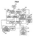
- Fig. 8 shows an example of an overall construction of a disk controller and a storage system in accordance with a conventional example.
- an operation input and a management program 235 on an SVP (Service Processor) 230 issue an instruction to a control program 217 and a device list 218 inside a disk controller 210 to register new storage as storage to be governed by the disk controller 210 itself, and to connect a corresponding new magnetic disk 220 to a back end FC I/F 213, whereby achieving extension of storage capacity.
- SVP Service Processor
- FC heterogeneous storage 227 having an FC device 225 is connected.
- storage refers collectively to magnetic disks, magnetic tape, etc.
- Heterogeneous storage refers to any storage medium that the disk controller does not manage directly.
- FC is an abbreviation for Fiber Channel.
- An example of an FC storage system is illustrated in an IBM white paper called “IBM Storage Tank TM, A Distributed Storage System", dated January 24, 2002.
- the storage where the remote copy is to be made does not necessarily have to be recognized by the disk controller as storage governed by the disk controller 210 itself. Therefore, it is also possible to use a SAN (Storage Area Network) 250 to connect a heterogeneous storage 229 having a front end FC I/F 212 and an FC device 260.
- SAN Storage Area Network
- the network is closed inside the disk controller. Therefore, since it is possible to learn the status of everything including the status of the FC heterogeneous storage and the status along the route thereto, it is possible to select the optimum storage when recording data.
- FC I/F storage system it is not possible to connect an IP network and iSCSI heterogeneous storage that are spread widely around the world. Therefore, in order to create a network on an IP-network scale, it is necessary to set up a separate network with just the FCs. Furthermore, management methods used on IP networks cannot be simply transferred and used on the storage system using the FC I/F described above.
- the iSCSI storage can be connected as the target, but only information about the target can be transmitted. Therefore, it is not possible to learn information about the performance of the network leading to the iSCSI storage, nor security, costs, or other such information about the IP network. Therefore, there was a problem in that it was not possible to connect optimally to the iSCSI heterogeneous storage in a way which took the status of the network into consideration.
- the present invention adopts mainly the following construction.
- a front end I/F and a back end I/F are provided to perform exchanges of information with network (connected) devices that are connected to a network and manage storage;
- the main memory section stores registered information expressing an attribution of the network (connected) devices, access information including information about security and performance of each network (connected) device through the network, and ranking information assigning a rank to each network (connected) device based on the registered information and the access information; and an appropriate network (connected) device is selected from various types of information including the ranking information stored in the main memory section, based on a condition requested by the computer.
- communication with the network (connected) devices uses iSCSI protocol or IP protocol.
- Embodiments of a disk controller of the present invention are explained in detail below, with Embodiment 1 and Embodiment 2 given as examples, and with reference made to the diagrams.
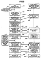
- Fig. 1 is a diagram showing an overall construction of Embodiment 1 of a disk controller and a storage system.
- a host 1 (100) and a host 2 (101) are connected to a disk controller 110 via a front end FC I/F 111, and can read and write data using FC protocol.
- the disk controller 110 controls data between the computer (below, "host") 100 and the host 2 (101) and a magnetic disk 120.
- a front end iSCSI I/F 112 which is an interface to IP networks 150, 151, 152.
- the front end iSCSI I/F 112 is used, for example, as an interface to heterogeneous storage (any storage which is not directly managed by the disk controller) for making a remote copy or a backup of data.
- the disk controller 110 has a back end FC I/F 113 as an interface to the magnetic disk 120, and the magnetic disk 120 is connected to the back end FC I/F 113. Furthermore, the disk controller 110 has a back end iSCSI I/F 114 and is connected to a magnetic disk 121, and the magnetic disk 121 is managed directly. Furthermore, the disk controller 110 has the back end iSCSI I/F 114 as an interface to iSCSI devices 160, 170 on the network, which are external devices connected via the networks 150, 151, 152. In other words, a router 140 or the iSCSI devices 160, 170 are connected to the backend iSCSI I/F 114 as devices on the network.
- the router 140 may also be a network switch.
- the iSCSI devices 160, 170 are connected to the front end iSCSI I/F 112 inside the disk controller 110 via the router 14 and the networks 150, 151, 152. Information is exchanged between the front end and the iSCSI devices. Furthermore, a cache memory 119 is provided along the route where the data is transferred from the front end FC I/F 111 to the back end FC I/F 113. The cache memory is used for high-speed data access.
- the entire disk controller 110 is controlled by a control processor 115.
- Programs, tables, lists, etc. are stored in a main memory 116.
- the disk controller 110 is provided with a SVP (service processor) 130 containing a management program 135.
- the SVP is connected to the control processor 115.
- the SVP 130 may be subordinate to the disk controller 110 and perform functions of a personal computer. In this case, a user can give instructions to the control processor 115 by performing input operations on the SVP 130.
- the SVP 130 may be connected to the disk controller 110 via a network and perform functions similar to the hosts.
- the main memory 116 there is a storage broker 117 as a program according to the present invention. This program performs control of the iSCSI devices. Moreover, the main memory 116 has a device list 118 serving as a database storing information that is necessary when connecting to the iSCSI devices 160, 170.
- the front end iSCSI I/F 112 and the back end iSCSI I/F 114 are connected via the router 140 to the networks 150, 151, 152, and the router 140 sends IPpackets from each interface to the networks 150, 151, 152 in such a manner as correctly corresponds to the addresses of the IP packets.
- the iSCSI devices 160, 170 are connected to the networks 150, 151, 152.
- storage broker replying (micro) programs 165, 175 as programs for exchanging information with the storage broker 117.
- the storage connected to the iSCSI devices 160, 170 includes, for example, iSCSI heterogeneous storage 167 and a heterogeneous magnetic tape disk 125 and the like, which are not directly managed by the disk controller 110 .
- iSCSI heterogeneous storage 167 and a heterogeneous magnetic tape disk 125 and the like which are not directly managed by the disk controller 110 .
- information about the networks 150, 151, 152 e.g., their performance, security, cost, etc.
- information stored in the router 140 This information can be utilized by applying the protocol that is normally used.
- SNMP is for example.
- Information about the iSCSI devices 160, 170 can be collected during negotiation and other procedures performed during iSCSI Login processing. Ranking of the iSCSI devices 160, 170 will be explained below, using a device list in Fig. 2.
- the device registration, deletion, test accessing and transmission/reception of data that the storage broker 117 of the disk controller 110 performs over the network with the storage broker replying (micro) programs 165, 175 in the iSCSI devices 160, 170 are performed via the front end iSCSI I/F 112 or the back end iSCSI I/F 114. That is, based on an instruction from the control processor 115 that controls the overall disk controller 110, the storage broker 117 sends a device registration request and the like (see step 400 in Fig. 3 described below) through the front end iSCSI I/F 112 or the back end iSCSI I/F 114 to the iSCSI devices' 160, 170.
- Methods for the control processor 115 to manage the iSCSI devices 160, 170 on the network include: a first method, in which the control processor 115 manages everything just like the magnetic disk 121 which the control processor 115 itself governs, or a second method, in which the management is yielded to the iSCSI device. If the first method is used, the control processor itself manages the iSCSI devices 160, 170 on the network, so data distribution and other detailed controls become possible. If the second method is used, the control processor yields the data management to the iSCSI devices on the network, and thus it becomes possible to reduce the control processor's management overhead. Whether to use the first method or the second method may be determined by the control processor based on it's own load, or by an instruction from the SVP by the user.
- the device registration, deletion, test accessing and transmission/reception of data that the storage broker 117 performs with the storage broker replying (micro) programs 165, 175 of the iSCSI devices 160, 170 on the network are executed according to controls by the control processor 115.
- the control processor can use either the front end iSCSI I/F 112 or the back end iSCSI I/F 114 to execute the registration, etc. Basically, it is not necessary to distinguish between usage the front end I/F and the back end I/F, so either end I/F may be used. In a typical example of usage, for backing up and for remote copying, the control processor may perform controls so that the front end I/F is used.
- controls may be performed to use the back end I/F (adding a magnetic disk to be managed directly by the control processor is similar to the normal processing method using the back end I/F.) Furthermore, whether to use the front end I/F or the back end I/F may be determined by the control processor according to an instruction from the SVP made by the user.
- each of the iSCSI devices 160, 170 can be connected to each of the networks 150, 151, 152 as a way to deal with a case where an accident occurs on one of the networks.
- the X mark on the connection line between the network and the iSCSI device indicates a network accident. Also, in Fig.
- the disk controller 110 in response to the data write request from the host, the disk controller 110 generally selects the magnetic disks 120, 121 that are directly managed by the disk controller, but in the case of a request to write voluminous data that cannot all be stored on the magnetic disks 120, 121, or in a case where the capacity of empty space on the magnetic disks 120, 121 has become small, or in a case where copy data is to be stored onto a storage medium other than the magnetic disks 120, 121, the data is written onto the external heterogeneous storage or heterogeneous storage medium via the network.
- Fig. 2 is a structural diagram of a device list according to Embodiment 1 of the disk controller.
- Rank 310 indicates a priority level with which a new connection will be made to each registered iSCSI device on the network in response to a request from the host or the SVP.
- ISCSI-Name 320 indicates an address of each iSCSI device.
- Capacity of Empty Area 330 indicates usable data capacity in each iSCSI device.
- Transfer Speed or Delay 340 indicates a data transfer speed or amount of time required to transfer data, which should be expected when accessing each of the iSCSI devices.
- Security 350 indicates the safety of the routes from the iSCSI devices 160, 170 to the disk controller 110, as determined based on the number of incidences that have occurred there in the past, the security configured there, etc.
- Running or Resting 360 indicates the current running state of each iSCSI device 160, 170.
- Cost 370 indicates the cost necessary to use each iSCSI device 160, 170.
- the storage broker 117 determines the rank of each of the registered iSCSI devices 160, 170 as relevant to a condition requested by the disk controller 110.
- the requested condition may be, for example, a condition requiring that voluminous writing be necessary, a condition requiring that the data to be handled be important or confidential, or a condition requiring that the disk controller itself have detected and learned its own load status, for example, such as how fast or slow its transfer speed is, or the volume that is too large to write, etc.
- An example of a way to determine the rank is to assign ranks to the entries from 320 to 370 for each device, and then, based on the condition requested by the disk controller 110, assign weight to those entries which are considered important, and then total these up to calculate the ultimate rank.
- a specific method for assigning the ranks could be, for example to numerically express (standardize) those which can be numerically expressed as "Xij" (where "i” represents the device names written vertically in Fig. 2, and "j" represents the entries written horizontally in Fig. 2), and then multiply these by weights W1, W2, W3, ... Wi provided by the SVP 130 (where a greater value of "Wi" indicates greater importance), and then assign the ranks according to the size of the value (Rank-i) thus produced.
- Rank1 W1 ⁇ X11 + W2 ⁇ X12 + W3 ⁇ X13 + ...
- Rank2 W1 ⁇ X21 + W2 ⁇ X22 + W3 ⁇ X23 + ...
- the SVP 130 since the SVP 130 is connected via the router 140 and the networks 150, 151, 152 to each of the iSCSI devices and thus has connections similar to the control processor 115, the SVP 130 can also perform the ranking of each of the registered iSCSI devices similarly to how ranking is performed by the control processor 115 as described above. The results of the ranking are stored in the device list 118 via the control processor. Note that it is self-evident that the user can add entries that are necessary besides those shown in Fig. 2.
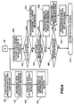
- Fig. 3 is a f low chart showing an example of device registration, testing, updating and accessing between the disk controller and the iSCSI device on the network in accordance with Embodiment 1.
- a device registration start command is transmitted from one of the hosts 100, 101 or the SVP 130 to the disk controller 110 (405).
- the control processor 115 of the disk controller 110 issues an iSCSI device registration request to the network's iSCSI devices 160, 170 and storage broker replying (micro) programs 165, 175 (400).
- the iSCSI devices 160, 170 that received the request then register their own device information (410).
- the storage broker 117 registers the iSCSI device(s) that replied into the device list 118 (420).
- the storage broker 117 assigns ranks to the information of the registered iSCSI devices (430). Furthermore, the storage broker 117 performs a test access to the registered iSCSI devices (s) or or the router 140 that is en route thereto, and collects information about the network status, etc. (440).
- the router 140 or iSCSI devices 160, 170 on which the test access was performed then reply to the test access (450). If the iSCSI devices 160, 170 have had their own device information (e.g. , their capacity of empty area, etc.) updated, they register the change in information with the storage broker 117 (455). Once the information is finished being changed with the storage broker 117, the storage broker 117 assigns ranks to the iSCSI device information once again (460).
- the iSCSI devices 160, 170 have had their own device information (e.g. , their capacity of empty area, etc.) updated, they register the change in information with the storage broker 117 (455). Once the information is finished being changed with the storage broker 117, the storage broker 117 assigns ranks to the iSCSI device information once again (460).
- a device request to add a device or create a journal log or perform a backup or a remote copy is sent to the storage broker 117 from an external location (e.g., the host or SVP) (470), a connection is then established to the iSCSI device with the highest rank and this device is registered (475).
- the registered iSCSI device also changes the registration of its own device information (476).
- step 475 is processing to add new storage to the disk device that is already present and under the management of the disk controller.
- the decision to add the storage is made according to the capacity of the magnetic disks being managed by the disk controller. That is, the request to add the storage is made when the existing disk capacity will not satisfy the write request from the host (when safety factors are also considered) .
- the decision to add the storage can also be made according to the I/O transaction number, transfer rate, control processor usage rate or other aspect of the performance of the disk controller itself. That is, a method is used in which the disk controller judges the decrease in the I/O transaction number or the like and then yields the storage management to the iSCSI devices, and the new storage is added.
- the storage broker 117 chooses the iSCSI device with the highest rank in the device list 118, and according to this selection the disk controller 110 performs the iSCSI login and the data access (480).
- the accessed iSCSI device 160, 170 then performs normal iSCSI command processing (490).
- the processing performed by the storage broker 117 returns to 440, and the storage broker replying (micro) programs 165, 175 return to 450.
- the disk controller can also perform deletion of the registered iSCSI device as part of the normal processing.
- the disk controller performs processing to delete the information for the corresponding iSCSI device from the device list and inform the iSCSI device that it has been cut off from the disk controller.
- the disk controller can obtain the information about the devices connected on the network and the security information that is obtained when each device is accessed, etc. Based on this information, the devices are then ranked, which is then stored in the device list serving as the database. The optimum network device can then be selected based on the rankings in the device list. Note that, in certain cases (such as when there is a request from the user) the network device can be selected according to items other than the rankings.
- Fig. 4 is a diagram showing a flowchart of registration, testing, updating and accessing by the storage broker device in accordance with Embodiment 1.
- the registration of the iSCSI device in the disk controller 110 (or, more specifically, in the storage broker 117) is started (500).
- the disk controller 110 broadcasts the iSCSI device registration request on the network (510).
- the disk controller 110 registers the iSCSI device that replied into the device list 118 (515) , and assigns the rank within the registered device list 118 (520).
- the test access is then performed on the registered device or the router 140 (535).
- a check is performed to determine whether or not the device list 118 needs to be updated (540).
- the disk controller 110 re-assigns the ranks to the devices in accordance with the update information (545). If an update is not necessary, then the check is performed to determine whether or not there is device list update information from an external location (550). If an update is necessary, then the ranks are re-assigned to the devices in accordance with the update information (555). If the update is not necessary, then a check is performed to determine whether or not there are various types of device requests (560). If a device request has occurred, then a connection is made to the iSCSI device with the highest rank and this device is registered (561). The processing at step 561 corresponds to the processing at step 475 shown in Fig.
- the iSCSI Login and the data access are then executed for the optimum device in the device list 118 (565). If there is no request, or after the request processing is completed, then the procedure returns to test access A at 535 (570).
- Fig. 5 is a diagram showing a flowchart of iSCSI device registration, test reporting and a device list change, in accordance with Embodiment 1.
- the iSCSI device starts iSCSI device processing (600).
- the iSCSI device collects its own iSCSI device information and registration conditions (610).
- the iSCSI device checks to determine whether or not there is a device list registration request from the disk controller (615). If there is a registration request, then the device information is registered into the corresponding storage broker 117 in the disk controller.
- the iSCSI device checks to determine whether or not a test access has been performed from an outside location (625).
- the iSCSI device replies to the storage broker 117 with the results of the access test (630). Furthermore, the iSCSI device checks to determine whether or not the update list 118 needs to be updated (635). If the update is necessary, then the registered information is updated in the corresponding storage broker 117 (640).
- the iSCSI device checks whether the device has been accessed (645). If the device has been accessed, then normal iSCSI device target processing is performed (650). If the device has not been accessed, then the procedure returns to step 610 where the iSCSI device collects its own iSCSI device information and registration conditions.
- Fig. 6 is a diagram showing an example of mirroring, backing up and system log data storage in accordance with Embodiment 1 of the disk controller.
- data A 800 is stored as master data on the magnetic disk 120.
- data A 850 is stored as slave data in the iSCSI heterogeneous storage 167 as the data A 850.
- the data A 800 and the data A 850 are synchronized.
- data C 820 is stored as master data on the magnetic disk 120.
- backup data is stored as old data C 870 in the iSCSI heterogeneous storage 167.
- the disk controller records the storage system's access status. When an accident occurs, the old data C 870 from the backup data is used, and system log data 880 for restoring the original data is stored onto a magnetic disk 125 where broad capacity is available in the first place.
- Embodiment 1 of the disk controller As explained above, when Embodiment 1 of the disk controller is used, wide-ranging storage connected to the IP network becomes usable, and the desired storage capacity can be realized. Note that, Embodiment 1 was explained with respect to the construction in which the disk controller has the magnetic disk 120 which the disk controller manages directly. However, in the disk controller of Embodiment 1, the subject of the invention is that it can be connected over the network to the storage or the magnetic disks. Therefore, the present invention is not restricted to the construction explained above. A construction which does not have the directly managed magnetic disk naturally falls within the scope of the present invention as well. (This is also the same for Embodiment 2.)
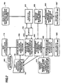
- Fig. 7 is a diagram showing an example of device registration, testing, updating and accessing between a disk controller and an iSCSI device in accordance with Embodiment 2.
- a command to start device registration is sent to the disk controller 110 from one of the hosts 100, 101 or the SVP 130 (805).
- device list registration is performed according to an operation input from the SVP 130 or the management program 135 (800).
- the disk controller 110 performs a test access to the iSCSI device or the router, obtains necessary information, and transmits this to the SVP 130.
- the storage broker 117 assigns the device ranks in accordance with this update information (860), and then transmits these rankings to the SVP.
- Fig. 7 all of the data to be written into the device list 118 is disclosed from the SVP 130 (800, 840, 860).
- the SVP 130 gives instructions for the processing of step 400 (the iSCSI device registration request), step 410 (the device's own information registration), and step 420 (the registration of the iSCSI device that replied into the device list) , which are shown in Fig. 3.
- the subsequent data flow is similar to Fig. 3.
- Embodiment 2 when Embodiment 2 is used, the procedures can progress without spending time on registering and checking the devices. Furthermore, the ranking of the registered iSCSI devices can also be performed by the SVP 130 like the ranking performed by the control processor 115 as described above. (See the description of ranking in Embodiment 1.)
- the disk controller of the present invention can be summarized as follows:
- iSCSI devices connected on a common IP network cannot be used to connect heterogeneous storage.
- equipment costs become expensive, and in a case where common iSCSI devices are connected, it is difficult for the disk controller side to accurately learn the status of the devices, so the heterogeneous connection could not be established easily.
- the device list is provided inside the disk controller in order to register the status of the externally connected IP network, the capacity of the iSCSI devices, the transfer rate, security, etc., and to assign the ranks.
- the storage broker in the disk controller updates the various conditions.
- the iSCSI device is connected based on the device list.
- the iSCSI I/F can be used to optimally select from many heterogeneous storage entities existing externally via the IP network. Therefore, costs can be reduced and storage capacity can be expanded.
Abstract
Description
Claims (16)
- A disk control unit comprising:wherein the front end I/F (111) and the back end I/F (113) exchange information with a network (connected) device (160,170) connected to a network (150,151,152) and managing storage,a front end I/F (111) which is an interface to a computer (100,101);a back end I/F (113) which is an interface to a magnetic disk (120,121);a processor (115) for controlling each section; anda main memory section (116),
wherein the main memory section (116) stores registered information expressing an attribution of the network (connected) device (160,170), access information including security and performance of each network (connected) device (160,170) through the network (150,151,152), and ranking information assigning a rank to each network (connected) device (160,170) based on the registered information and the access information,
wherein the processor (115) selects an appropriate network (connected) device (160,170) from various types of information including the ranking information stored in the main memory section (116), based on a condition requested by the computer (100,101). - The disk control unit according to claim 1, wherein communication with the network (connected) device (160,170) uses iSCSI protocol or IP protocol.
- The disk control unit according to claim 1, wherein the main memory section (116) is provided with a storage broker (117) as a control program for performing control on the network (connected) device (160,170) managing the storage, and is provided with a device list (118) storing the registered information, the access information, and the ranking information.
- The disk control unit according to claim 1, wherein the processor (115) obtains the registered information from a replying (micro) program (165,175) built into the network (connected) device (160,170), and obtains the access information upon accessing each network (connected) device (160,170) via the network (150,151,152).
- The disk control unit according to claim 4, wherein an SVP (Service Processor) (130) with a built-in management program (135) is connected to the processor (115),
wherein the processor (115) obtains the registered information and the access information from terminal operations on the SVP (130), or from the management program (135). - The disk control unit according to claim 5, wherein the information exchange with the network (connected) device (160,170) is performed via the front end I/F (111) that can be connected to the computer (100,101).
- The disk control unit according to claim 5, wherein the information exchange with the network (connected) device (160,170) is performed via the back end I/F (113) that can be connected to the magnetic disk (120) being managed by the disk control unit.
- The disk control unit according to claim 1, wherein the storage managed by the network (connected) device (160,170) has an iSCSI I/F.
- The disk control unit according to claim 4, wherein the processor (115) obtains the registered information and the access information via a router (140) or a network switch.
- The disk control unit according to claim 1, wherein the processor selects the network (connected) device (160,170) to which to write mirrored data or backup data based on the registered information, the access information and the ranking information, in addition to the magnetic disk (120,121) managed by the disk control unit.
- The disk control unit according to claim 1, wherein the processor (115) selects the network (connected) device (160,170) to which to write log data accessed from the host (100,101) based on the registered information, the access information and the ranking information.
- A storage system comprising:wherein the disk control unit (110) further comprises:a disk control unit (110); anda disk unit connected to the disk control unit (110),wherein the front end I/F (111) and the back end I/F (113) provided to the disk control unit (110) are connected to a network (connected) device (160,170) via a network (150,151,152),a front end I/F (111) which is an interface to a computer;a back end I/F (113) which is an interface to a magnetic disk (120);a processor (115) for controlling each section; anda main memory section (116),
wherein the main memory section (116) inside the disk control unit (110) stores registered information expressing an attribution of the network (connected) device (160,170), access information including security and performance of each network (connected) device (160,170) through the network (150,151,152), and ranking information assigning a rank to each network (connected) device (160,170) based on the registered information and the access information,
wherein the disk control unit (110) selects an appropriate network (connected) device (160,170) from various types of information including the ranking information stored in the main memory section (116), based on a condition requested by the computer (100,101). - The storage system according to claim 12, wherein the communication with the network (connected) device uses iSCSI protocol or IP protocol.
- The storage system according to claim 12, wherein the processor (115) obtains the registered information from a replying (micro) program (165,175) built into the network (connected) device (160,170), and obtains the access information upon accessing each network (connected) device (160,170) via the network (150, 151, 152).
- The storage system according to claim 14, wherein the disk control unit (110) is connected to an SVP (Service Processor) (130),
wherein the processor (115) obtains the registered information and the access information from terminal operations on the SVP (130), or from a management program (135) executed by the SVP (130). - A storage system comprising:wherein the disk control unit (110) further comprises:a disk control unit (110); anda disk unit connected to the disk control unit (110),wherein the front end I/F (111) and the back end I/F (113) provided to the disk control unit (110) are connected to a network (connected) device (160,170) via a network (150,151,152),a front end I/F (111) which is an interface to a computer (100,101);a back end I/F (113) which is an interface to a magnetic disk (120,121);a processor (115) for controlling each section; anda main memory section (116),
wherein the main memory section (116) stores, as a device list (118) registered information expressing an attribution of the network (connected) device (160,170) obtained from a replying (micro) program (165,175) built into the network (connected) device (160,170), access information including security and performance of each network (connected) device (160,170) obtained upon accessing each network (connected) device (160,170) via the network (150,151,152), and ranking information assigning a rank to each network (connected) device (160,170) based on the registered information and the access information, and the main memory section (116) further stores a control program for performing control on the network (connected) device (160,170) as a storage broker (117),
wherein an appropriate network (connected) device (160,170) is selected from the device list (118) including the ranking information stored in the main memory section (116), based on a condition requested by the computer (100,101).
Applications Claiming Priority (2)
| Application Number | Priority Date | Filing Date | Title |
|---|---|---|---|
| JP2004082824A JP2005267546A (en) | 2004-03-22 | 2004-03-22 | Disk controller, and system for managing connection of network connection storage in the disk controller |
| JP2004082824 | 2004-03-22 |
Publications (2)
| Publication Number | Publication Date |
|---|---|
| EP1580655A2 true EP1580655A2 (en) | 2005-09-28 |
| EP1580655A3 EP1580655A3 (en) | 2008-08-13 |
Family
ID=34858375
Family Applications (1)
| Application Number | Title | Priority Date | Filing Date |
|---|---|---|---|
| EP04025943A Withdrawn EP1580655A3 (en) | 2004-03-22 | 2004-11-02 | Disk control unit and storage system |
Country Status (3)
| Country | Link |
|---|---|
| US (3) | US7302498B2 (en) |
| EP (1) | EP1580655A3 (en) |
| JP (1) | JP2005267546A (en) |
Cited By (2)
| Publication number | Priority date | Publication date | Assignee | Title |
|---|---|---|---|---|
| WO2008021276A1 (en) * | 2006-08-11 | 2008-02-21 | Hewlett-Packard Development Company, L.P. | Data-object-related-request routing in a dynamic, distributed data-storage system |
| EP2487637A1 (en) * | 2009-09-07 | 2012-08-15 | Fujitsu Limited | Member management system, member management device, and program |
Families Citing this family (13)
| Publication number | Priority date | Publication date | Assignee | Title |
|---|---|---|---|---|
| KR100662120B1 (en) * | 2003-10-20 | 2006-12-27 | 엘지전자 주식회사 | Method for using in common memory of household appliances for home networking |
| JP2005267546A (en) * | 2004-03-22 | 2005-09-29 | Hitachi Ltd | Disk controller, and system for managing connection of network connection storage in the disk controller |
| US20060036908A1 (en) * | 2004-08-10 | 2006-02-16 | Fabrice Helliker | System for backup storage device selection |
| US7913043B2 (en) | 2004-05-14 | 2011-03-22 | Bakbone Software, Inc. | Method for backup storage device selection |
| US8386661B2 (en) * | 2005-11-18 | 2013-02-26 | Leviton Manufacturing Co., Inc. | Communication network for controlling devices |
| JP2007141183A (en) * | 2005-11-22 | 2007-06-07 | Hitachi Ltd | Storage controller and storage control method |
| JP2009077044A (en) * | 2007-09-19 | 2009-04-09 | Toshiba Corp | Broadcast receiving device and method |
| US8850029B2 (en) * | 2008-02-14 | 2014-09-30 | Mcafee, Inc. | System, method, and computer program product for managing at least one aspect of a connection based on application behavior |
| US8752042B2 (en) * | 2008-08-27 | 2014-06-10 | Cardinalcommerce Corporation | Intelligent server routing |
| US10025523B1 (en) * | 2009-12-28 | 2018-07-17 | EMC IP Holding Company LLC | Techniques for processing data requests directed to virtualized devices |
| US8239532B1 (en) * | 2010-06-24 | 2012-08-07 | Google Inc. | System and method of reducing latency using adaptive DNS resolution |
| US9652482B2 (en) * | 2012-12-31 | 2017-05-16 | Teradata Us, Inc. | Data storage management based on indicated storage levels and other criteria for multilevel storage systems |
| US20180052736A1 (en) * | 2016-08-18 | 2018-02-22 | International Business Machines Corporation | Initializing storage unit performance rankings in new computing devices of a dispersed storage network |
Citations (3)
| Publication number | Priority date | Publication date | Assignee | Title |
|---|---|---|---|---|
| US6389432B1 (en) | 1999-04-05 | 2002-05-14 | Auspex Systems, Inc. | Intelligent virtual volume access |
| US20030018656A1 (en) | 2001-07-19 | 2003-01-23 | Schutzman Neil F. | Attribute based resource allocation |
| WO2003021441A1 (en) | 2001-08-31 | 2003-03-13 | Arkivio, Inc. | Techniques for storing data based upon storage policies |
Family Cites Families (27)
| Publication number | Priority date | Publication date | Assignee | Title |
|---|---|---|---|---|
| US5544347A (en) | 1990-09-24 | 1996-08-06 | Emc Corporation | Data storage system controlled remote data mirroring with respectively maintained data indices |
| US5666511A (en) * | 1992-10-08 | 1997-09-09 | Fujitsu Limited | Deadlock suppressing schemes in a raid system |
| US5491810A (en) | 1994-03-01 | 1996-02-13 | International Business Machines Corporation | Method and system for automated data storage system space allocation utilizing prioritized data set parameters |
| EP1152409B1 (en) * | 1994-06-07 | 2006-08-09 | Hitachi Global Storage Technologies Japan, Ltd. | Information storing device |
| US5845319A (en) * | 1995-08-23 | 1998-12-01 | Fujitsu Limited | Disk array device which separates local and physical disks using striping and operation mode selection |
| US6092066A (en) | 1996-05-31 | 2000-07-18 | Emc Corporation | Method and apparatus for independent operation of a remote data facility |
| US5941972A (en) * | 1997-12-31 | 1999-08-24 | Crossroads Systems, Inc. | Storage router and method for providing virtual local storage |
| US5996024A (en) | 1998-01-14 | 1999-11-30 | Emc Corporation | Method and apparatus for a SCSI applications server which extracts SCSI commands and data from message and encapsulates SCSI responses to provide transparent operation |
| US6366931B1 (en) | 1998-11-20 | 2002-04-02 | Hewlett-Packard Company | Apparatus for and method of non-linear constraint optimization in storage system configuration |
| US6864991B1 (en) * | 1999-02-09 | 2005-03-08 | Canon Kabushiki Kaisha | Information processing apparatus for displaying data related to image forming apparatus, and information processing method therefor |
| JP2001014112A (en) * | 1999-06-29 | 2001-01-19 | Hitachi Ltd | Disk subsystem and remote copying method |
| JP3568110B2 (en) * | 1999-10-15 | 2004-09-22 | インターナショナル・ビジネス・マシーンズ・コーポレーション | Cache memory control method, computer system, hard disk drive, and hard disk controller |
| US8218555B2 (en) * | 2001-04-24 | 2012-07-10 | Nvidia Corporation | Gigabit ethernet adapter |
| US7200646B2 (en) * | 2001-04-25 | 2007-04-03 | Sun Microsystems, Inc. | System and method for on-demand node creation for fabric devices |
| US7343410B2 (en) * | 2001-06-28 | 2008-03-11 | Finisar Corporation | Automated creation of application data paths in storage area networks |
| US20030105830A1 (en) * | 2001-12-03 | 2003-06-05 | Duc Pham | Scalable network media access controller and methods |
| US6785771B2 (en) * | 2001-12-04 | 2004-08-31 | International Business Machines Corporation | Method, system, and program for destaging data in cache |
| US7433948B2 (en) * | 2002-01-23 | 2008-10-07 | Cisco Technology, Inc. | Methods and apparatus for implementing virtualization of storage within a storage area network |
| US6785794B2 (en) | 2002-05-17 | 2004-08-31 | International Business Machines Corporation | Differentiated storage resource provisioning |
| JP3966076B2 (en) * | 2002-05-29 | 2007-08-29 | 株式会社日立製作所 | Centralized storage management method |
| US7415723B2 (en) * | 2002-06-11 | 2008-08-19 | Pandya Ashish A | Distributed network security system and a hardware processor therefor |
| JP2004021557A (en) * | 2002-06-14 | 2004-01-22 | Hitachi Ltd | Program, information processing method, information processor, and storage device |
| JP3977698B2 (en) | 2002-07-05 | 2007-09-19 | 株式会社日立製作所 | Storage control device, storage control device control method, and program |
| US7124260B2 (en) * | 2002-08-26 | 2006-10-17 | Micron Technology, Inc. | Modified persistent auto precharge command protocol system and method for memory devices |
| US7587587B2 (en) * | 2002-12-05 | 2009-09-08 | Broadcom Corporation | Data path security processing |
| US20050097335A1 (en) * | 2003-10-31 | 2005-05-05 | Hewlett-Packard Development Company, L.P. | Secure document access method and apparatus |
| JP2005267546A (en) | 2004-03-22 | 2005-09-29 | Hitachi Ltd | Disk controller, and system for managing connection of network connection storage in the disk controller |
-
2004
- 2004-03-22 JP JP2004082824A patent/JP2005267546A/en active Pending
- 2004-05-25 US US10/852,111 patent/US7302498B2/en not_active Expired - Fee Related
- 2004-08-24 US US10/923,732 patent/US7600047B2/en not_active Expired - Fee Related
- 2004-11-02 EP EP04025943A patent/EP1580655A3/en not_active Withdrawn
-
2009
- 2009-07-31 US US12/533,310 patent/US8032606B2/en not_active Expired - Fee Related
Patent Citations (3)
| Publication number | Priority date | Publication date | Assignee | Title |
|---|---|---|---|---|
| US6389432B1 (en) | 1999-04-05 | 2002-05-14 | Auspex Systems, Inc. | Intelligent virtual volume access |
| US20030018656A1 (en) | 2001-07-19 | 2003-01-23 | Schutzman Neil F. | Attribute based resource allocation |
| WO2003021441A1 (en) | 2001-08-31 | 2003-03-13 | Arkivio, Inc. | Techniques for storing data based upon storage policies |
Cited By (4)
| Publication number | Priority date | Publication date | Assignee | Title |
|---|---|---|---|---|
| WO2008021276A1 (en) * | 2006-08-11 | 2008-02-21 | Hewlett-Packard Development Company, L.P. | Data-object-related-request routing in a dynamic, distributed data-storage system |
| US7610383B2 (en) | 2006-08-11 | 2009-10-27 | Hewlett-Packard Development Company, L.P. | Data-object-related-request routing in a dynamic, distributed data-storage system |
| EP2487637A1 (en) * | 2009-09-07 | 2012-08-15 | Fujitsu Limited | Member management system, member management device, and program |
| EP2487637A4 (en) * | 2009-09-07 | 2013-04-03 | Fujitsu Ltd | Member management system, member management device, and program |
Also Published As
| Publication number | Publication date |
|---|---|
| US7302498B2 (en) | 2007-11-27 |
| JP2005267546A (en) | 2005-09-29 |
| US7600047B2 (en) | 2009-10-06 |
| US8032606B2 (en) | 2011-10-04 |
| US20050210156A1 (en) | 2005-09-22 |
| EP1580655A3 (en) | 2008-08-13 |
| US20090292868A1 (en) | 2009-11-26 |
| US20050210130A1 (en) | 2005-09-22 |
Similar Documents
| Publication | Publication Date | Title |
|---|---|---|
| US8032606B2 (en) | Disk control unit and storage system | |
| US8683482B2 (en) | Computer system for balancing access load of storage systems and control method therefor | |
| US7124169B2 (en) | Network system and its switches | |
| US7457925B2 (en) | Storage control method and system | |
| US7536592B2 (en) | Storage system and snapshot data preparation method in storage system | |
| US7467241B2 (en) | Storage control method and storage control system | |
| US8352678B2 (en) | Storage controller | |
| JP4744171B2 (en) | Computer system and storage control method | |
| US7386598B2 (en) | Computer system with virtualization function | |
| US20120159012A1 (en) | Storage system | |
| US7246161B2 (en) | Managing method for optimizing capacity of storage | |
| US7603538B2 (en) | Access environment construction system and method | |
| US20070005886A1 (en) | Disk array apparatus and control method for disk array apparatus | |
| US8285929B2 (en) | Management computer | |
| JP2003030012A5 (en) | ||
| JP2005275525A (en) | Storage system | |
| JP4285058B2 (en) | Network management program, management computer and management method | |
| JP2005190106A (en) | Storage control subsystem for managing logical volume | |
| EP2146284B1 (en) | Remote copy system and method | |
| CN101471830B (en) | Method for accessing remote logic equipment through multiple routes in Linux system | |
| US20110161520A1 (en) | Storage system for optimally controlling a plurality of data transfer paths and method therefor | |
| JP4474356B2 (en) | Computer system and storage virtualization apparatus | |
| US7545746B2 (en) | Computer system for controlling routed data amount | |
| JPWO2005010767A1 (en) | Data storage system | |
| JP2014021690A (en) | Data store managing device, data providing system and data providing method |
Legal Events
| Date | Code | Title | Description |
|---|---|---|---|
| PUAI | Public reference made under article 153(3) epc to a published international application that has entered the european phase |
Free format text: ORIGINAL CODE: 0009012 |
|
| AK | Designated contracting states |
Kind code of ref document: A2 Designated state(s): AT BE BG CH CY CZ DE DK EE ES FI FR GB GR HU IE IS IT LI LU MC NL PL PT RO SE SI SK TR |
|
| AX | Request for extension of the european patent |
Extension state: AL HR LT LV MK YU |
|
| PUAL | Search report despatched |
Free format text: ORIGINAL CODE: 0009013 |
|
| AK | Designated contracting states |
Kind code of ref document: A3 Designated state(s): AT BE BG CH CY CZ DE DK EE ES FI FR GB GR HU IE IS IT LI LU MC NL PL PT RO SE SI SK TR |
|
| AX | Request for extension of the european patent |
Extension state: AL HR LT LV MK YU |
|
| 17P | Request for examination filed |
Effective date: 20090213 |
|
| 17Q | First examination report despatched |
Effective date: 20090320 |
|
| AKX | Designation fees paid |
Designated state(s): DE FR GB IE |
|
| STAA | Information on the status of an ep patent application or granted ep patent |
Free format text: STATUS: THE APPLICATION HAS BEEN WITHDRAWN |
|
| 18W | Application withdrawn |
Effective date: 20100929 |