EP1579902A1 - Fuel deoxygenation system - Google Patents
Fuel deoxygenation system Download PDFInfo
- Publication number
- EP1579902A1 EP1579902A1 EP05251812A EP05251812A EP1579902A1 EP 1579902 A1 EP1579902 A1 EP 1579902A1 EP 05251812 A EP05251812 A EP 05251812A EP 05251812 A EP05251812 A EP 05251812A EP 1579902 A1 EP1579902 A1 EP 1579902A1
- Authority
- EP
- European Patent Office
- Prior art keywords
- fuel
- oxygen
- recited
- porous membrane
- channel
- Prior art date
- Legal status (The legal status is an assumption and is not a legal conclusion. Google has not performed a legal analysis and makes no representation as to the accuracy of the status listed.)
- Granted
Links
Images

Classifications
-
- B—PERFORMING OPERATIONS; TRANSPORTING
- B01—PHYSICAL OR CHEMICAL PROCESSES OR APPARATUS IN GENERAL
- B01D—SEPARATION
- B01D19/00—Degasification of liquids
-
- B—PERFORMING OPERATIONS; TRANSPORTING
- B01—PHYSICAL OR CHEMICAL PROCESSES OR APPARATUS IN GENERAL
- B01D—SEPARATION
- B01D19/00—Degasification of liquids
- B01D19/0031—Degasification of liquids by filtration
-
- B—PERFORMING OPERATIONS; TRANSPORTING
- B01—PHYSICAL OR CHEMICAL PROCESSES OR APPARATUS IN GENERAL
- B01D—SEPARATION
- B01D61/00—Processes of separation using semi-permeable membranes, e.g. dialysis, osmosis or ultrafiltration; Apparatus, accessories or auxiliary operations specially adapted therefor
-
- C—CHEMISTRY; METALLURGY
- C10—PETROLEUM, GAS OR COKE INDUSTRIES; TECHNICAL GASES CONTAINING CARBON MONOXIDE; FUELS; LUBRICANTS; PEAT
- C10G—CRACKING HYDROCARBON OILS; PRODUCTION OF LIQUID HYDROCARBON MIXTURES, e.g. BY DESTRUCTIVE HYDROGENATION, OLIGOMERISATION, POLYMERISATION; RECOVERY OF HYDROCARBON OILS FROM OIL-SHALE, OIL-SAND, OR GASES; REFINING MIXTURES MAINLY CONSISTING OF HYDROCARBONS; REFORMING OF NAPHTHA; MINERAL WAXES
- C10G31/00—Refining of hydrocarbon oils, in the absence of hydrogen, by methods not otherwise provided for
- C10G31/11—Refining of hydrocarbon oils, in the absence of hydrogen, by methods not otherwise provided for by dialysis
-
- F—MECHANICAL ENGINEERING; LIGHTING; HEATING; WEAPONS; BLASTING
- F02—COMBUSTION ENGINES; HOT-GAS OR COMBUSTION-PRODUCT ENGINE PLANTS
- F02C—GAS-TURBINE PLANTS; AIR INTAKES FOR JET-PROPULSION PLANTS; CONTROLLING FUEL SUPPLY IN AIR-BREATHING JET-PROPULSION PLANTS
- F02C7/00—Features, components parts, details or accessories, not provided for in, or of interest apart form groups F02C1/00 - F02C6/00; Air intakes for jet-propulsion plants
- F02C7/22—Fuel supply systems
- F02C7/224—Heating fuel before feeding to the burner
-
- B—PERFORMING OPERATIONS; TRANSPORTING
- B01—PHYSICAL OR CHEMICAL PROCESSES OR APPARATUS IN GENERAL
- B01D—SEPARATION
- B01D19/00—Degasification of liquids
- B01D19/0005—Degasification of liquids with one or more auxiliary substances
-
- F—MECHANICAL ENGINEERING; LIGHTING; HEATING; WEAPONS; BLASTING
- F23—COMBUSTION APPARATUS; COMBUSTION PROCESSES
- F23K—FEEDING FUEL TO COMBUSTION APPARATUS
- F23K2900/00—Special features of, or arrangements for fuel supplies
- F23K2900/05082—Removing gaseous substances from liquid fuel line, e.g. oxygen
Definitions
- the present invention relates to stabilizing fuel by deoxygenation, and more particularly to deoxygenation through a self-supporting porous membrane adjacent an oxygen receiving channel.
- Jet fuel is often utilized in aircraft as a coolant for various aircraft systems.
- the presence of dissolved oxygen in hydrocarbon jet fuels may be objectionable because the oxygen supports oxidation reactions that yield undesirable by-products.
- Dissolution of air in jet fuel results in an approximately 70 ppm oxygen concentration.
- aerated fuel is heated between 350°F (177°C) and 850°F (454°C) the oxygen initiates free radical reactions of the fuel resulting in deposits commonly referred to as "coke” or "coking.” Coke may be detrimental to the fuel lines and may inhibit combustion. The formation of such deposits may impair the normal functioning of a fuel system, either with respect to an intended heat exchange function or the efficient injection of fuel.
- FSU Fuel Stabilization Unit
- One conventional Fuel Stabilization Unit (FSU) utilized in aircraft removes oxygen from jet fuel by producing an oxygen pressure gradient across a membrane permeable to oxygen.
- the gradient is produced by vacuum on one side of the membrane.
- the membrane is supported on a porous stainless steel backing plate, which is relatively expensive to manufacture and may be a diffusion barrier requiring a relative increase in the FSU size.
- the membrane is relatively thin ( ⁇ 2-5 microns) and lacks mechanical integrity, hence the porous backing.
- Mechanical pumps and vacuum housings are also required to generate the pressure gradient which further increases the size and weight of the FSU.
- Such thin membranes (2-5 microns) may have defects and pin-holes. Fuel may then seep through the membrane and accumulating in the backing which results in further resistance to deoxygenation.
- the fuel system for an energy conversion device includes a deoxygenator system with a self-supporting porous membrane.
- a sweep gas and/or vacuum maintains an oxygen concentration differential across the membrane to deoxygenate the fuel.
- a fuel condenser is incorporated down stream of a nitrogen bleed to recover any fuel carried away by the sweep gas.
- oxygen is removed in multiple stages which operates at sequentially elevated fuel temperatures as the fuel is utilized as a coolant for a multiple of heat exchange subsystems.
- the present invention therefore provides, at least in its preferred embodiments, a method and system for the deoxygenation of hydrocarbon fuel in an inexpensive, size and weight efficient system that avoids the relatively heavy machinery required to produce a vacuum across a relatively thin membrane.
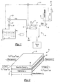
- FIG. 1 illustrates a general schematic view of a fuel system 10 for an energy conversion device (ECD) 12.
- a deoxygenator system 14 receives liquid fuel F from a reservoir 16.
- the fuel F is typically a hydrocarbon such as jet fuel.
- the ECD 12 may exist in a variety of forms in which the fuel, at some point prior to eventual use for processing, for combustion or for some form of energy release, acquires sufficient heat to support autoxidation reactions and coking if dissolved oxygen is present to any significant extent in the fuel.
- ECD 12 is a gas turbine engine, and particularly such engines in high performance aircraft.
- the fuel also serves as a coolant for one or more sub-systems in the aircraft, and in any event becomes heated as it is delivered to fuel injectors immediately prior to combustion.
- a heat exchange section 18 represents a system through which the fuel passes in a heat exchange relationship. It should be understood that the heat exchange section 18 may be directly associated with the ECD 12 and/or distributed elsewhere in the larger system.
- the heat exchange system 18 may alternatively or additionally include a multiple of heat exchanges distributed throughout the system.
- fuel F stored in the reservoir 16 normally contains dissolved oxygen, possibly at a saturation level of 70 ppm.
- a fuel pump 20 draws the fuel F from the reservoir 16.
- the fuel pump 20 communicates with the reservoir 16 via a fuel reservoir conduit 22 and a valve 24 to a fuel inlet 26 of the deoxygenator system 14.
- the pressure applied by pump 20 assists in circulating the fuel F through the deoxygenator system 14 and other portions of the fuel system 10.
- oxygen is selectively removed into a sweep gas system 28.
- the deoxygenated fuel Fd flows from a fuel outlet 30 of the deoxygenation system 14 via a deoxygenated fuel conduit 32, to the heat exchange system 18 and to the ECD 12 such as the fuel injectors of a gas turbine engine.
- a portion of the deoxygenated fuel may be recirculated, as represented by recirculation conduit 33 to either the deoxygenation system 14 and/or the reservoir 16.
- the deoxygenator system 14 preferably includes a gas/fuel contactor 34 with a self-supporting Oxygen permeable porous membrane 36 between a fuel channel 38 and an oxygen receiving channel such as a sweep gas channel 40.
- the sweep gas channel 40 preferably contains nitrogen and/or another inert gas. It should be understood that the channels may be of various shapes and arrangements to provide a pressure differential, which maintains an oxygen concentration differential across the membrane to deoxygenate the fuel.
- the fuel and the sweep gas preferably flow in opposite directions.
- U is the velocity
- C O2 is the Oxygen concentration in the fuel
- L is the thickness of the channel/layer
- Z is the length of the channel
- P is the pressure.
- the subscripts or superscripts, s refers to sweep gas, f to the fuel, in to flow inlet, out to the flow outlet, and m to the membrane 36.
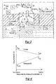
- the movement of the sweep gas (e.g. N 2 ) within the sweep gas channel 40 maintains a concentration differential across the membrane 36 ( Figure 3).
- the flux of oxygen through the membrane is proportional to the diffusivity of oxygen in the sweep gas, and is given as
- D O2 is the diffusion coefficient of oxygen in the sweep gas
- C O2 is the Oxygen concentration
- L m is the thickness of the porous membrane
- Z is the length of the channel
- b is the width of the channel
- H fuel-N2 is the thermodynamic distribution coefficient between fuel and sweep gas (N 2 ).
- the subscript m refers to the membrane while superscript s refers to sweep gas and f to the fuel. It is assumed that the concentration of oxygen in the sweep gas is negligible.
- L' m is the thickness of the membrane
- H fuel-membrane is the thermodynamic distribution coefficient between fuel and membrane.
- Diffusion coefficient of oxygen in the membrane is more than 3 orders magnitude lower than that of the diffusion coefficient of oxygen in a sweep gas like N 2 .
- the present invention utilizes the porous membrane with a thickness ( Figure 3) that is an order of magnitude greater than the heretofore utilized thin non-porous membrane.
- the ratio of the distribution coefficients H fuel-N 2 / H fuel-membrane is typically less than 1, indicating an improvement in performance with the porous membrane 36 of the present invention.
- the membrane 36 includes a multiple of pores 42 (one shown). Two basic paths for Oxygen removal from the fuel are: 1) through the membrane 36 sweep gas interface; and 2) through fuel-sweep gas interface within a pore 42. Normally, the latter is the least resistance path.
- P is the pressure.
- the subscripts s refers to sweep gas, f to the fuel, in to the flow inlet and out to the flow outlet.
- C O2 is the Oxygen concentration in the fuel.
- D O2 is the diffusion coefficient of oxygen in the sweep gas, L is the thickness of the channel/layer, Z is the length of the channel, b is the width of the channel, and H is the thermodynamic distribution coefficient.
- Fuel is prevented from flowing through the pores 42 of the porous membrane 36 by maintaining a pressure differential across the membrane which is lower than the capillary force of the fuel Fc in a pore 42 of radius r p .
- the pressure differential also provides a pressure on the sweep gas side which is lower than the pressure on the fuel side to prevent the sweep gas from bubbling through the pores 42 into the fuel.
- the surface tension ⁇ of kerosene is 25 dynes/cm or 0.025 Nm -1 .
- the contact angle ⁇ is ⁇ 140° for JP-8 on Teflon AF-2400 membrane, and for a maximum pore radius of r p of 1 micron, a pressure differential of 10 kPa will prevent fuel from leaking to the sweep gas.
- the contact angle between the fuel and the porous membrane is preferably non perpendicular. Most preferably, the contact angle ⁇ is greater than 90°.
- a deoxygenator system 14A includes a gas/fuel contactor 34A between a fuel circuit and a sweep gas circuit.
- the fuel flows cocurrent or counter-current to the sweep-gas.
- the sweep gas containing relatively higher amounts of oxygen after the gas/fuel contactor 34A is purged of oxygen through a recycle blower 44 and a purge system 48 such that pure nitrogen is added to the sweep gas circuit from a sweep gas reservoir 46 to maintain low concentrations of oxygen ( C s O2 ) back into the gas/fuel contactor 34A.
- the driving force for oxygen across the membrane in this system is calculated by the following equation:
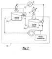
- a deoxygenator system 14B includes a gas/fuel contactor 34B between the fuel circuit and a sweep gas circuit.
- the sweep gas may absorb fuel that leaks through the membrane 36.
- a nitrogen bleed 48 from the sweep gas circuit is condensed in a fuel condenser system 50 to separate the fuel from the gaseous mixture of sweep gas and oxygen.
- the condensed fuel from the condenser system 50 is then returned to the fuel reservoir 16, while the gaseous mixture is vented.
- the gaseous mixture from the fuel condenser system 50 is sent to the sweep gas reservoir 46.
- a deoxygenator system 14C includes a multiple of gas/fuel contactors 34C1, 34C2 ... 34Cn between the fuel circuit and a sweep gas circuit.
- the gas-fuel contactors 34Cl, 34C2... 34Cn preferably operate at sequentially elevated fuel temperatures as the fuel is utilized as a coolant for a multiple of heat exchange sections Q1, Q2...Qn such as fuel-oil heat exchange subsystems along the fuel circuit. Elevated fuel temperature facilitates oxygen removal by decreasing the solubility of oxygen (decreasing H fuel-N2 ) in the fuel and increasing diffusion coefficient of oxygen in the fuel/membrane ( D O 2 , D m ), hence providing higher driving force for removal of oxygen and/or a lower volume system.
- Elevated fuel temperatures directly translate to a decrease in the gas-fuel contactor volume, due to favorable thermodynamic effects which are generally proportional to the operating temperature of the fuel.
- Fuel heating at a multiple of heat exchange section Q1- Qn permits a multiple of in-series fuel-gas contactors 34C1, 34C2... 34Cn to enable higher fuel heating, without coking, as the oxygen content in the fuel is decreased at the end of each stage. That is, although the fuel temperature is higher after being utilized to cool an earlier heat exchange section, the higher temperature fuel requires a smaller fuel gas contactor at the next stage to achieve generally equivalent oxygen reduction.
- the fuel is thereby progressively deoxygenated and increased in temperature as the fuel flows through the fuel system.
Landscapes
- Engineering & Computer Science (AREA)
- Chemical & Material Sciences (AREA)
- Combustion & Propulsion (AREA)
- Chemical Kinetics & Catalysis (AREA)
- General Engineering & Computer Science (AREA)
- Mechanical Engineering (AREA)
- Oil, Petroleum & Natural Gas (AREA)
- Water Supply & Treatment (AREA)
- General Chemical & Material Sciences (AREA)
- Organic Chemistry (AREA)
- Separation Using Semi-Permeable Membranes (AREA)
- Degasification And Air Bubble Elimination (AREA)
- Production Of Liquid Hydrocarbon Mixture For Refining Petroleum (AREA)
- Feeding And Controlling Fuel (AREA)
- Separation By Low-Temperature Treatments (AREA)
Abstract
Description


Claims (22)
- A fuel system comprising:a fuel channel (38);an oxygen receiving channel (40); andan oxygen permeable porous membrane (36) in communication with said fuel channel (38) and said oxygen receiving channel (40).
- The fuel system as recited in claim 1, wherein said oxygen permeable porous membrane (36) is generally parallel to said fuel channel (38) and said oxygen receiving channel (40).
- The fuel system as recited in claim 1, wherein said oxygen permeable porous membrane (36) is non-perpendicular to said fuel channel (38).
- The fuel system as recited in claim 1, 2 or 3, wherein said oxygen receiving channel (40) communicates an inert gas therethrough.
- The fuel system as recited in any preceding claim, wherein said fuel channel (38) communicates a liquid fuel containing a dissolved oxygen therethrough, said oxygen permeable porous membrane (36) operable to separate the dissolved oxygen from the fuel.
- The fuel system as recited in any preceding claim, wherein said oxygen permeable porous membrane (36) is unsupported.
- The fuel system as recited in any preceding claim, wherein said fuel channel (38) communicates a liquid fuel in a first direction and said oxygen receiving channel (40) communicates a gas in a direction opposite the first direction.
- The fuel system as recited in any preceding claim, further comprising a pressure differential across said oxygen permeable porous membrane (36), said pressure differential lower than a capillary force of the fuel within a pore (42) of said oxygen permeable porous membrane (36).
- The fuel system as recited in any preceding claim, wherein said oxygen receiving channel (40) comprises a sweep gas.
- The fuel system as recited in any of claims 1 to 8, wherein said oxygen receiving channel (40) comprises a vacuum.
- A fuel system comprising:a fuel channel (38);an oxygen receiving channel (40); anda gas/fuel contactor (34) in communication with said fuel channel (3 8) and said oxygen receiving channel (40).
- The fuel system as recited in claim 11 further comprising a fuel condenser (50) in communication with said oxygen receiving channel (40).
- The fuel system as recited in claim 11 or 12, further comprising a sweep gas reservoir (46) in communication with said oxygen receiving channel (40).
- The fuel system as recited in claim 11, 12 or 13 further comprising a second gas/fuel contactor (34C2) in communication with said fuel channel (38) and said oxygen receiving channel (40), said second gas/fuel contactor (34C2) in series with said gas fuel contactor (34C1).
- The fuel system as recited in claim 14, wherein said second gas/fuel contactor (34C2) receives fuel at a fuel temperature greater than a fuel temperature of said gas/fuel contactor (34Cl).
- The fuel system as recited in any of claims 11 to 15, wherein said gas/fuel contactor (34) comprises an unsupported oxygen permeable porous membrane (36) in communication with said fuel channel (38) and said oxygen receiving channel (40).
- A method of minimizing dissolved oxygen from within a fuel system comprising the steps of:(1) locating an oxygen permeable porous membrane (36) adjacent a liquid fuel flow containing a dissolved oxygen; and(2) flowing a sweep gas along the oxygen permeable porous membrane (36) to draw the oxygen through the oxygen permeable porous membrane (36).
- A method as recited in claim 17, wherein said step (2) further comprises the steps of:flowing the gas in a direction opposite a direction of the liquid fuel flow.
- A method as recited in claim 17 or 18, wherein said step (1) further comprises
locating the oxygen permeable porous membrane (36) non-perpendicular to said fuel flow. - A method as recited in claim 17, 18 or 19, further comprising the steps of:maintaining a pressure differential across the oxygen permeable porous membrane (36), the pressure differential lower than a capillary force of the fuel within a pore (42) of the oxygen permeable porous membrane (36).
- A method as recited in any of claims 17 to 20, further comprising the steps of:maintaining a pressure differential across the oxygen permeable porous membrane (36), the pressure differential comprising a pressure on the sweep gas side (40) lower than a pressure on the fuel side (38).
- A method as recited in any of claims 17 to 21, further comprising the steps of:communicating the sweep gas to a fuel condenser (50) downstream of the oxygen permeable porous membrane (36); andcondensing the fuel from within the sweep gas.
Applications Claiming Priority (2)
| Application Number | Priority Date | Filing Date | Title |
|---|---|---|---|
| US10/808,151 US7153343B2 (en) | 2004-03-24 | 2004-03-24 | Fuel deoxygenation system |
| US808151 | 2004-03-24 |
Publications (2)
| Publication Number | Publication Date |
|---|---|
| EP1579902A1 true EP1579902A1 (en) | 2005-09-28 |
| EP1579902B1 EP1579902B1 (en) | 2009-02-25 |
Family
ID=34862068
Family Applications (1)
| Application Number | Title | Priority Date | Filing Date |
|---|---|---|---|
| EP05251812A Active EP1579902B1 (en) | 2004-03-24 | 2005-03-23 | Fuel deoxygenation system |
Country Status (8)
| Country | Link |
|---|---|
| US (1) | US7153343B2 (en) |
| EP (1) | EP1579902B1 (en) |
| JP (1) | JP2005272841A (en) |
| KR (1) | KR100656871B1 (en) |
| CN (1) | CN1673034A (en) |
| AT (1) | ATE423605T1 (en) |
| CA (1) | CA2496929A1 (en) |
| DE (1) | DE602005012881D1 (en) |
Cited By (6)
| Publication number | Priority date | Publication date | Assignee | Title |
|---|---|---|---|---|
| EP1723996A2 (en) * | 2005-05-18 | 2006-11-22 | United Technologies Corporation | Modular fuel stabilization system |
| EP1827646A2 (en) * | 2004-11-30 | 2007-09-05 | Phyre Technologies, Inc. | Contacting systems and methods and uses thereof |
| EP2540366A3 (en) * | 2011-06-30 | 2013-03-06 | United Technologies Corporation | Fuel deoxygenation using surface-modified porous membranes |
| GB2538623A (en) * | 2015-05-21 | 2016-11-23 | Rolls Royce Plc | Engine lubrication system using de-Oxygenated fuel |
| CN110092002A (en) * | 2018-01-30 | 2019-08-06 | 哈米尔顿森德斯特兰德公司 | The fuel tank of aircraft is catalyzed inerting equipment |
| CN110092001A (en) * | 2018-01-29 | 2019-08-06 | 哈米尔顿森德斯特兰德公司 | The fuel tank of aircraft is catalyzed inerting equipment |
Families Citing this family (36)
| Publication number | Priority date | Publication date | Assignee | Title |
|---|---|---|---|---|
| US20050274649A1 (en) * | 2004-06-09 | 2005-12-15 | Spadaccini Louis J | Method for suppressing oxidative coke formation in liquid hydrocarbons containing metal |
| US7465335B2 (en) * | 2005-02-02 | 2008-12-16 | United Technologies Corporation | Fuel deoxygenation system with textured oxygen permeable membrane |
| US7465336B2 (en) * | 2005-06-09 | 2008-12-16 | United Technologies Corporation | Fuel deoxygenation system with non-planar plate members |
| US7537646B2 (en) * | 2005-10-11 | 2009-05-26 | United Technologies Corporation | Fuel system and method of reducing emission |
| US7615104B2 (en) * | 2005-11-03 | 2009-11-10 | United Technologies Corporation | Fuel deoxygenation system with multi-layer oxygen permeable membrane |
| US7632338B2 (en) * | 2006-10-05 | 2009-12-15 | United Technologies Corporation | Electrochemical oxygen pump for fuel stabilization unit |
| US20080098894A1 (en) * | 2006-11-01 | 2008-05-01 | Sabatino Daniel R | Acoustic degassing heat exchanger |
| US7882704B2 (en) * | 2007-01-18 | 2011-02-08 | United Technologies Corporation | Flame stability enhancement |
| US8056345B2 (en) * | 2007-06-13 | 2011-11-15 | United Technologies Corporation | Hybrid cooling of a gas turbine engine |
| US20090020013A1 (en) * | 2007-07-20 | 2009-01-22 | Sloan Michael A | Membrane based deoxygenator for processing fluids |
| US8038770B2 (en) * | 2008-12-01 | 2011-10-18 | Eaton Corporation | Separator for degassing fluid |
| US8177884B2 (en) * | 2009-05-20 | 2012-05-15 | United Technologies Corporation | Fuel deoxygenator with porous support plate |
| US8388830B2 (en) | 2010-06-25 | 2013-03-05 | Uop Llc | Process for upgrading sweetened or oxygen-contaminated kerosene or jet fuel, to minimize or eliminate its tendency to polymerize or foul when heated |
| US8388740B2 (en) | 2010-10-27 | 2013-03-05 | Uop Llc | Simplified process to remove dissolved oxygen from hydrocarbon streams |
| DE102011003449B4 (en) * | 2011-02-01 | 2016-04-07 | Siemens Aktiengesellschaft | An electrical appliance with a cooling device comprising a device for reducing the oxygen concentration in a coolant in a coolant circuit and method therefor |
| US9580185B2 (en) | 2012-01-20 | 2017-02-28 | Hamilton Sundstrand Corporation | Small engine cooled cooling air system |
| US8876946B2 (en) | 2012-04-03 | 2014-11-04 | Hamilton Sundstrand Corporation | Combined fuel stabilization unit and heat exchanger |
| GB201217332D0 (en) * | 2012-09-28 | 2012-11-14 | Rolls Royce Plc | A gas turbine engine |
| WO2014163685A1 (en) | 2013-03-12 | 2014-10-09 | Rolls-Royce North American Technologies, Inc. | Deoxygenation of liquid with gas |
| US9687773B2 (en) | 2014-04-30 | 2017-06-27 | Honeywell International Inc. | Fuel deoxygenation and fuel tank inerting system and method |
| US9789972B2 (en) * | 2014-06-27 | 2017-10-17 | Hamilton Sundstrand Corporation | Fuel and thermal management system |
| US9656187B2 (en) | 2014-11-12 | 2017-05-23 | Honeywell International Inc. | Fuel deoxygenation system contactor-separator |
| US9834315B2 (en) | 2014-12-15 | 2017-12-05 | Honeywell International Inc. | Aircraft fuel deoxygenation system |
| US9897054B2 (en) | 2015-01-15 | 2018-02-20 | Honeywell International Inc. | Centrifugal fuel pump with variable pressure control |
| DE102016208571A1 (en) * | 2015-06-08 | 2016-12-08 | Robert Bosch Gmbh | Arrangement for the provision of germ-free water for injections |
| US10329027B2 (en) | 2016-07-15 | 2019-06-25 | Hamilton Sundstrand Corporation | Fuel deoxygenation systems |
| US20190022558A1 (en) * | 2017-07-24 | 2019-01-24 | Hamilton Sundstrand Corporation | Fuel tank de-oxygenation system |
| US10655569B2 (en) * | 2017-08-24 | 2020-05-19 | Hamilton Sundstrand Corporation | Leakage prevention systems and methods |
| US11078846B2 (en) | 2018-07-30 | 2021-08-03 | Hamilton Sunstrand Corporation | Fuel delivery system |
| US10994226B2 (en) * | 2018-09-13 | 2021-05-04 | Hamilton Sunstrand Corporation | Fuel deoxygenation with a spiral contactor |
| US11319085B2 (en) | 2018-11-02 | 2022-05-03 | General Electric Company | Fuel oxygen conversion unit with valve control |
| US20200318539A1 (en) * | 2019-04-05 | 2020-10-08 | General Electric Company | Pump Mixer Separator Unit |
| US10914274B1 (en) * | 2019-09-11 | 2021-02-09 | General Electric Company | Fuel oxygen reduction unit with plasma reactor |
| CN110749641A (en) * | 2019-11-04 | 2020-02-04 | 盐城工学院 | Sensor for monitoring nitrate concentration in water body in real time |
| US11866182B2 (en) | 2020-05-01 | 2024-01-09 | General Electric Company | Fuel delivery system having a fuel oxygen reduction unit |
| EP4015395A1 (en) * | 2020-12-16 | 2022-06-22 | Airbus Operations, S.L.U. | Aircraft and method of operating an aircraft comprising an air separation device |
Citations (3)
| Publication number | Priority date | Publication date | Assignee | Title |
|---|---|---|---|---|
| US4729773A (en) * | 1986-03-04 | 1988-03-08 | Erma Inc. | Unit for degassing liquids |
| US6315815B1 (en) * | 1999-12-16 | 2001-11-13 | United Technologies Corporation | Membrane based fuel deoxygenator |
| US6709492B1 (en) * | 2003-04-04 | 2004-03-23 | United Technologies Corporation | Planar membrane deoxygenator |
Family Cites Families (8)
| Publication number | Priority date | Publication date | Assignee | Title |
|---|---|---|---|---|
| US5619855A (en) | 1995-06-07 | 1997-04-15 | General Electric Company | High inlet mach combustor for gas turbine engine |
| US5888275A (en) | 1996-02-26 | 1999-03-30 | Japan Gore-Tex, Inc. | Assembly for deaeration of liquids |
| JPH1193694A (en) | 1997-09-18 | 1999-04-06 | Toshiba Corp | Gas turbine plant |
| US6672072B1 (en) | 1998-08-17 | 2004-01-06 | General Electric Company | Pressure boosted compressor cooling system |
| US6562104B2 (en) | 2000-12-19 | 2003-05-13 | Praxair Technology, Inc. | Method and system for combusting a fuel |
| JP2003327408A (en) | 2002-05-10 | 2003-11-19 | Mitsubishi Electric Corp | Fuel treatment apparatus and operation method thereof |
| US6939392B2 (en) | 2003-04-04 | 2005-09-06 | United Technologies Corporation | System and method for thermal management |
| US7041154B2 (en) * | 2003-12-12 | 2006-05-09 | United Technologies Corporation | Acoustic fuel deoxygenation system |
-
2004
- 2004-03-24 US US10/808,151 patent/US7153343B2/en active Active
-
2005
- 2005-02-11 CA CA002496929A patent/CA2496929A1/en not_active Abandoned
- 2005-03-07 KR KR1020050018514A patent/KR100656871B1/en not_active IP Right Cessation
- 2005-03-22 JP JP2005082725A patent/JP2005272841A/en active Pending
- 2005-03-23 DE DE602005012881T patent/DE602005012881D1/en active Active
- 2005-03-23 EP EP05251812A patent/EP1579902B1/en active Active
- 2005-03-23 AT AT05251812T patent/ATE423605T1/en not_active IP Right Cessation
- 2005-03-24 CN CNA2005100591996A patent/CN1673034A/en active Pending
Patent Citations (3)
| Publication number | Priority date | Publication date | Assignee | Title |
|---|---|---|---|---|
| US4729773A (en) * | 1986-03-04 | 1988-03-08 | Erma Inc. | Unit for degassing liquids |
| US6315815B1 (en) * | 1999-12-16 | 2001-11-13 | United Technologies Corporation | Membrane based fuel deoxygenator |
| US6709492B1 (en) * | 2003-04-04 | 2004-03-23 | United Technologies Corporation | Planar membrane deoxygenator |
Cited By (10)
| Publication number | Priority date | Publication date | Assignee | Title |
|---|---|---|---|---|
| EP1827646A2 (en) * | 2004-11-30 | 2007-09-05 | Phyre Technologies, Inc. | Contacting systems and methods and uses thereof |
| EP1827646A4 (en) * | 2004-11-30 | 2012-02-15 | Phyre Technologies Inc | Contacting systems and methods and uses thereof |
| EP1723996A2 (en) * | 2005-05-18 | 2006-11-22 | United Technologies Corporation | Modular fuel stabilization system |
| EP1723996A3 (en) * | 2005-05-18 | 2008-06-11 | United Technologies Corporation | Modular fuel stabilization system |
| US7435283B2 (en) | 2005-05-18 | 2008-10-14 | United Technologies Corporation | Modular fuel stabilization system |
| EP2540366A3 (en) * | 2011-06-30 | 2013-03-06 | United Technologies Corporation | Fuel deoxygenation using surface-modified porous membranes |
| US8741029B2 (en) | 2011-06-30 | 2014-06-03 | United Technologies Corporation | Fuel deoxygenation using surface-modified porous membranes |
| GB2538623A (en) * | 2015-05-21 | 2016-11-23 | Rolls Royce Plc | Engine lubrication system using de-Oxygenated fuel |
| CN110092001A (en) * | 2018-01-29 | 2019-08-06 | 哈米尔顿森德斯特兰德公司 | The fuel tank of aircraft is catalyzed inerting equipment |
| CN110092002A (en) * | 2018-01-30 | 2019-08-06 | 哈米尔顿森德斯特兰德公司 | The fuel tank of aircraft is catalyzed inerting equipment |
Also Published As
| Publication number | Publication date |
|---|---|
| US7153343B2 (en) | 2006-12-26 |
| KR100656871B1 (en) | 2006-12-19 |
| ATE423605T1 (en) | 2009-03-15 |
| JP2005272841A (en) | 2005-10-06 |
| CA2496929A1 (en) | 2005-09-24 |
| EP1579902B1 (en) | 2009-02-25 |
| KR20060043440A (en) | 2006-05-15 |
| DE602005012881D1 (en) | 2009-04-09 |
| CN1673034A (en) | 2005-09-28 |
| US20050211096A1 (en) | 2005-09-29 |
Similar Documents
| Publication | Publication Date | Title |
|---|---|---|
| EP1579902A1 (en) | Fuel deoxygenation system | |
| EP1731209B1 (en) | Fuel Deoxygenation system with non-planar plate members | |
| EP1580252B1 (en) | Electrochemical fuel deoxygenation system | |
| US7824470B2 (en) | Method for enhancing mass transport in fuel deoxygenation systems | |
| US7465335B2 (en) | Fuel deoxygenation system with textured oxygen permeable membrane | |
| Böddeker | Terminology in pervaporation | |
| US7803275B2 (en) | Membrane separation process using mixed vapor-liquid feed | |
| EP1782879A1 (en) | Fuel deoxygenation system with multi-layer oxygen permeable membrane | |
| KR20090038901A (en) | Improved membrane separation process using mixed vapor-liquid feed | |
| US20110195344A1 (en) | Passive water drain | |
| EP3434752A1 (en) | Fuel tank de-oxygenation system | |
| US20200197834A1 (en) | Composite hollow fiber membranes for jet fuel de-oxygenation | |
| EP3434347A1 (en) | Fuel tank de-oxygenation system | |
| CN111742131B (en) | On-board fuel separation of on-demand octane number using membrane distillation | |
| EP3546372A1 (en) | Precooling for fuel vaporization in use with catalytic fuel tank inerting | |
| US8876946B2 (en) | Combined fuel stabilization unit and heat exchanger | |
| LT et al. | Vorrichtung zum Entzug von Sauerstoff im Kraftstoff Système de déoxygénation de carburant | |
| US20060196174A1 (en) | Catalytic fuel deoxygenation system | |
| US20200197835A1 (en) | Composite hollow fiber membranes for jet fuel de-oxygenation | |
| US10442546B2 (en) | Cavitation mitigation in catalytic oxidation fuel tank inerting systems | |
| US20080292919A1 (en) | System and Method for Reducing Radiator Sizes for Low Temperature Fuel Cell Systems |
Legal Events
| Date | Code | Title | Description |
|---|---|---|---|
| PUAI | Public reference made under article 153(3) epc to a published international application that has entered the european phase |
Free format text: ORIGINAL CODE: 0009012 |
|
| AK | Designated contracting states |
Kind code of ref document: A1 Designated state(s): AT BE BG CH CY CZ DE DK EE ES FI FR GB GR HU IE IS IT LI LT LU MC NL PL PT RO SE SI SK TR |
|
| AX | Request for extension of the european patent |
Extension state: AL BA HR LV MK YU |
|
| RIN1 | Information on inventor provided before grant (corrected) |
Inventor name: BURLATSKY, SERGEI F. Inventor name: LAMM, FOSTER PHILIP Inventor name: SPADACCINI, LOUIS J. Inventor name: GUMMALLA, MALLIKA |
|
| 17P | Request for examination filed |
Effective date: 20060208 |
|
| AKX | Designation fees paid |
Designated state(s): AT BE BG CH CY CZ DE DK EE ES FI FR GB GR HU IE IS IT LI LT LU MC NL PL PT RO SE SI SK TR |
|
| 17Q | First examination report despatched |
Effective date: 20060320 |
|
| GRAP | Despatch of communication of intention to grant a patent |
Free format text: ORIGINAL CODE: EPIDOSNIGR1 |
|
| GRAS | Grant fee paid |
Free format text: ORIGINAL CODE: EPIDOSNIGR3 |
|
| GRAA | (expected) grant |
Free format text: ORIGINAL CODE: 0009210 |
|
| AK | Designated contracting states |
Kind code of ref document: B1 Designated state(s): AT BE BG CH CY CZ DE DK EE ES FI FR GB GR HU IE IS IT LI LT LU MC NL PL PT RO SE SI SK TR |
|
| REG | Reference to a national code |
Ref country code: GB Ref legal event code: FG4D |
|
| REG | Reference to a national code |
Ref country code: CH Ref legal event code: EP |
|
| REG | Reference to a national code |
Ref country code: IE Ref legal event code: FG4D |
|
| REF | Corresponds to: |
Ref document number: 602005012881 Country of ref document: DE Date of ref document: 20090409 Kind code of ref document: P |
|
| PG25 | Lapsed in a contracting state [announced via postgrant information from national office to epo] |
Ref country code: FI Free format text: LAPSE BECAUSE OF FAILURE TO SUBMIT A TRANSLATION OF THE DESCRIPTION OR TO PAY THE FEE WITHIN THE PRESCRIBED TIME-LIMIT Effective date: 20090225 Ref country code: LT Free format text: LAPSE BECAUSE OF FAILURE TO SUBMIT A TRANSLATION OF THE DESCRIPTION OR TO PAY THE FEE WITHIN THE PRESCRIBED TIME-LIMIT Effective date: 20090225 Ref country code: SI Free format text: LAPSE BECAUSE OF FAILURE TO SUBMIT A TRANSLATION OF THE DESCRIPTION OR TO PAY THE FEE WITHIN THE PRESCRIBED TIME-LIMIT Effective date: 20090225 Ref country code: NL Free format text: LAPSE BECAUSE OF FAILURE TO SUBMIT A TRANSLATION OF THE DESCRIPTION OR TO PAY THE FEE WITHIN THE PRESCRIBED TIME-LIMIT Effective date: 20090225 |
|
| NLV1 | Nl: lapsed or annulled due to failure to fulfill the requirements of art. 29p and 29m of the patents act | ||
| PG25 | Lapsed in a contracting state [announced via postgrant information from national office to epo] |
Ref country code: SE Free format text: LAPSE BECAUSE OF FAILURE TO SUBMIT A TRANSLATION OF THE DESCRIPTION OR TO PAY THE FEE WITHIN THE PRESCRIBED TIME-LIMIT Effective date: 20090525 Ref country code: IS Free format text: LAPSE BECAUSE OF FAILURE TO SUBMIT A TRANSLATION OF THE DESCRIPTION OR TO PAY THE FEE WITHIN THE PRESCRIBED TIME-LIMIT Effective date: 20090625 Ref country code: PL Free format text: LAPSE BECAUSE OF FAILURE TO SUBMIT A TRANSLATION OF THE DESCRIPTION OR TO PAY THE FEE WITHIN THE PRESCRIBED TIME-LIMIT Effective date: 20090225 Ref country code: AT Free format text: LAPSE BECAUSE OF FAILURE TO SUBMIT A TRANSLATION OF THE DESCRIPTION OR TO PAY THE FEE WITHIN THE PRESCRIBED TIME-LIMIT Effective date: 20090225 |
|
| PG25 | Lapsed in a contracting state [announced via postgrant information from national office to epo] |
Ref country code: BE Free format text: LAPSE BECAUSE OF FAILURE TO SUBMIT A TRANSLATION OF THE DESCRIPTION OR TO PAY THE FEE WITHIN THE PRESCRIBED TIME-LIMIT Effective date: 20090225 |
|
| PG25 | Lapsed in a contracting state [announced via postgrant information from national office to epo] |
Ref country code: DK Free format text: LAPSE BECAUSE OF FAILURE TO SUBMIT A TRANSLATION OF THE DESCRIPTION OR TO PAY THE FEE WITHIN THE PRESCRIBED TIME-LIMIT Effective date: 20090225 Ref country code: PT Free format text: LAPSE BECAUSE OF FAILURE TO SUBMIT A TRANSLATION OF THE DESCRIPTION OR TO PAY THE FEE WITHIN THE PRESCRIBED TIME-LIMIT Effective date: 20090812 Ref country code: CZ Free format text: LAPSE BECAUSE OF FAILURE TO SUBMIT A TRANSLATION OF THE DESCRIPTION OR TO PAY THE FEE WITHIN THE PRESCRIBED TIME-LIMIT Effective date: 20090225 Ref country code: EE Free format text: LAPSE BECAUSE OF FAILURE TO SUBMIT A TRANSLATION OF THE DESCRIPTION OR TO PAY THE FEE WITHIN THE PRESCRIBED TIME-LIMIT Effective date: 20090225 Ref country code: MC Free format text: LAPSE BECAUSE OF NON-PAYMENT OF DUE FEES Effective date: 20090331 Ref country code: ES Free format text: LAPSE BECAUSE OF FAILURE TO SUBMIT A TRANSLATION OF THE DESCRIPTION OR TO PAY THE FEE WITHIN THE PRESCRIBED TIME-LIMIT Effective date: 20090605 |
|
| REG | Reference to a national code |
Ref country code: CH Ref legal event code: PL |
|
| PG25 | Lapsed in a contracting state [announced via postgrant information from national office to epo] |
Ref country code: RO Free format text: LAPSE BECAUSE OF FAILURE TO SUBMIT A TRANSLATION OF THE DESCRIPTION OR TO PAY THE FEE WITHIN THE PRESCRIBED TIME-LIMIT Effective date: 20090225 Ref country code: SK Free format text: LAPSE BECAUSE OF FAILURE TO SUBMIT A TRANSLATION OF THE DESCRIPTION OR TO PAY THE FEE WITHIN THE PRESCRIBED TIME-LIMIT Effective date: 20090225 |
|
| PLBE | No opposition filed within time limit |
Free format text: ORIGINAL CODE: 0009261 |
|
| STAA | Information on the status of an ep patent application or granted ep patent |
Free format text: STATUS: NO OPPOSITION FILED WITHIN TIME LIMIT |
|
| REG | Reference to a national code |
Ref country code: IE Ref legal event code: MM4A |
|
| PG25 | Lapsed in a contracting state [announced via postgrant information from national office to epo] |
Ref country code: CH Free format text: LAPSE BECAUSE OF NON-PAYMENT OF DUE FEES Effective date: 20090331 Ref country code: LI Free format text: LAPSE BECAUSE OF NON-PAYMENT OF DUE FEES Effective date: 20090331 Ref country code: BG Free format text: LAPSE BECAUSE OF FAILURE TO SUBMIT A TRANSLATION OF THE DESCRIPTION OR TO PAY THE FEE WITHIN THE PRESCRIBED TIME-LIMIT Effective date: 20090525 Ref country code: IE Free format text: LAPSE BECAUSE OF NON-PAYMENT OF DUE FEES Effective date: 20090323 |
|
| 26N | No opposition filed |
Effective date: 20091126 |
|
| PG25 | Lapsed in a contracting state [announced via postgrant information from national office to epo] |
Ref country code: GR Free format text: LAPSE BECAUSE OF FAILURE TO SUBMIT A TRANSLATION OF THE DESCRIPTION OR TO PAY THE FEE WITHIN THE PRESCRIBED TIME-LIMIT Effective date: 20090526 Ref country code: FR Free format text: LAPSE BECAUSE OF NON-PAYMENT OF DUE FEES Effective date: 20090427 |
|
| REG | Reference to a national code |
Ref country code: FR Ref legal event code: ST Effective date: 20100930 |
|
| PG25 | Lapsed in a contracting state [announced via postgrant information from national office to epo] |
Ref country code: IT Free format text: LAPSE BECAUSE OF FAILURE TO SUBMIT A TRANSLATION OF THE DESCRIPTION OR TO PAY THE FEE WITHIN THE PRESCRIBED TIME-LIMIT Effective date: 20090225 |
|
| PG25 | Lapsed in a contracting state [announced via postgrant information from national office to epo] |
Ref country code: LU Free format text: LAPSE BECAUSE OF NON-PAYMENT OF DUE FEES Effective date: 20090323 |
|
| PG25 | Lapsed in a contracting state [announced via postgrant information from national office to epo] |
Ref country code: HU Free format text: LAPSE BECAUSE OF FAILURE TO SUBMIT A TRANSLATION OF THE DESCRIPTION OR TO PAY THE FEE WITHIN THE PRESCRIBED TIME-LIMIT Effective date: 20090826 |
|
| PG25 | Lapsed in a contracting state [announced via postgrant information from national office to epo] |
Ref country code: TR Free format text: LAPSE BECAUSE OF FAILURE TO SUBMIT A TRANSLATION OF THE DESCRIPTION OR TO PAY THE FEE WITHIN THE PRESCRIBED TIME-LIMIT Effective date: 20090225 |
|
| PG25 | Lapsed in a contracting state [announced via postgrant information from national office to epo] |
Ref country code: CY Free format text: LAPSE BECAUSE OF FAILURE TO SUBMIT A TRANSLATION OF THE DESCRIPTION OR TO PAY THE FEE WITHIN THE PRESCRIBED TIME-LIMIT Effective date: 20090225 |
|
| REG | Reference to a national code |
Ref country code: DE Ref legal event code: R082 Ref document number: 602005012881 Country of ref document: DE Representative=s name: SCHMITT-NILSON SCHRAUD WAIBEL WOHLFROM PATENTA, DE |
|
| REG | Reference to a national code |
Ref country code: DE Ref legal event code: R082 Ref document number: 602005012881 Country of ref document: DE Representative=s name: SCHMITT-NILSON SCHRAUD WAIBEL WOHLFROM PATENTA, DE Ref country code: DE Ref legal event code: R081 Ref document number: 602005012881 Country of ref document: DE Owner name: UNITED TECHNOLOGIES CORP. (N.D.GES.D. STAATES , US Free format text: FORMER OWNER: UNITED TECHNOLOGIES CORP., HARTFORD, CONN., US |
|
| REG | Reference to a national code |
Ref country code: DE Ref legal event code: R081 Ref document number: 602005012881 Country of ref document: DE Owner name: RAYTHEON TECHNOLOGIES CORPORATION (N.D.GES.D.S, US Free format text: FORMER OWNER: UNITED TECHNOLOGIES CORP. (N.D.GES.D. STAATES DELAWARE), FARMINGTON, CONN., US |
|
| PGFP | Annual fee paid to national office [announced via postgrant information from national office to epo] |
Ref country code: GB Payment date: 20230222 Year of fee payment: 19 Ref country code: DE Payment date: 20230221 Year of fee payment: 19 |
|
| P01 | Opt-out of the competence of the unified patent court (upc) registered |
Effective date: 20230519 |